WO2020203066A1 - 表示制御装置及び表示制御プログラム - Google Patents
表示制御装置及び表示制御プログラム Download PDFInfo
- Publication number
- WO2020203066A1 WO2020203066A1 PCT/JP2020/009941 JP2020009941W WO2020203066A1 WO 2020203066 A1 WO2020203066 A1 WO 2020203066A1 JP 2020009941 W JP2020009941 W JP 2020009941W WO 2020203066 A1 WO2020203066 A1 WO 2020203066A1
- Authority
- WO
- WIPO (PCT)
- Prior art keywords
- lane change
- display
- notification content
- vehicle
- standby
- Prior art date
- Legal status (The legal status is an assumption and is not a legal conclusion. Google has not performed a legal analysis and makes no representation as to the accuracy of the status listed.)
- Ceased
Links
Images


Classifications
-
- G—PHYSICS
- G02—OPTICS
- G02B—OPTICAL ELEMENTS, SYSTEMS OR APPARATUS
- G02B27/00—Optical systems or apparatus not provided for by any of the groups G02B1/00 - G02B26/00, G02B30/00
- G02B27/01—Head-up displays
- G02B27/0101—Head-up displays characterised by optical features
-
- B—PERFORMING OPERATIONS; TRANSPORTING
- B60—VEHICLES IN GENERAL
- B60K—ARRANGEMENT OR MOUNTING OF PROPULSION UNITS OR OF TRANSMISSIONS IN VEHICLES; ARRANGEMENT OR MOUNTING OF PLURAL DIVERSE PRIME-MOVERS IN VEHICLES; AUXILIARY DRIVES FOR VEHICLES; INSTRUMENTATION OR DASHBOARDS FOR VEHICLES; ARRANGEMENTS IN CONNECTION WITH COOLING, AIR INTAKE, GAS EXHAUST OR FUEL SUPPLY OF PROPULSION UNITS IN VEHICLES
- B60K35/00—Instruments specially adapted for vehicles; Arrangement of instruments in or on vehicles
- B60K35/10—Input arrangements, i.e. from user to vehicle, associated with vehicle functions or specially adapted therefor
-
- B—PERFORMING OPERATIONS; TRANSPORTING
- B60—VEHICLES IN GENERAL
- B60K—ARRANGEMENT OR MOUNTING OF PROPULSION UNITS OR OF TRANSMISSIONS IN VEHICLES; ARRANGEMENT OR MOUNTING OF PLURAL DIVERSE PRIME-MOVERS IN VEHICLES; AUXILIARY DRIVES FOR VEHICLES; INSTRUMENTATION OR DASHBOARDS FOR VEHICLES; ARRANGEMENTS IN CONNECTION WITH COOLING, AIR INTAKE, GAS EXHAUST OR FUEL SUPPLY OF PROPULSION UNITS IN VEHICLES
- B60K35/00—Instruments specially adapted for vehicles; Arrangement of instruments in or on vehicles
- B60K35/20—Output arrangements, i.e. from vehicle to user, associated with vehicle functions or specially adapted therefor
- B60K35/21—Output arrangements, i.e. from vehicle to user, associated with vehicle functions or specially adapted therefor using visual output, e.g. blinking lights or matrix displays
- B60K35/23—Head-up displays [HUD]
- B60K35/235—Head-up displays [HUD] with means for detecting the driver's gaze direction or eye points
-
- B—PERFORMING OPERATIONS; TRANSPORTING
- B60—VEHICLES IN GENERAL
- B60K—ARRANGEMENT OR MOUNTING OF PROPULSION UNITS OR OF TRANSMISSIONS IN VEHICLES; ARRANGEMENT OR MOUNTING OF PLURAL DIVERSE PRIME-MOVERS IN VEHICLES; AUXILIARY DRIVES FOR VEHICLES; INSTRUMENTATION OR DASHBOARDS FOR VEHICLES; ARRANGEMENTS IN CONNECTION WITH COOLING, AIR INTAKE, GAS EXHAUST OR FUEL SUPPLY OF PROPULSION UNITS IN VEHICLES
- B60K35/00—Instruments specially adapted for vehicles; Arrangement of instruments in or on vehicles
- B60K35/20—Output arrangements, i.e. from vehicle to user, associated with vehicle functions or specially adapted therefor
- B60K35/28—Output arrangements, i.e. from vehicle to user, associated with vehicle functions or specially adapted therefor characterised by the type of the output information, e.g. video entertainment or vehicle dynamics information; characterised by the purpose of the output information, e.g. for attracting the attention of the driver
-
- B—PERFORMING OPERATIONS; TRANSPORTING
- B60—VEHICLES IN GENERAL
- B60K—ARRANGEMENT OR MOUNTING OF PROPULSION UNITS OR OF TRANSMISSIONS IN VEHICLES; ARRANGEMENT OR MOUNTING OF PLURAL DIVERSE PRIME-MOVERS IN VEHICLES; AUXILIARY DRIVES FOR VEHICLES; INSTRUMENTATION OR DASHBOARDS FOR VEHICLES; ARRANGEMENTS IN CONNECTION WITH COOLING, AIR INTAKE, GAS EXHAUST OR FUEL SUPPLY OF PROPULSION UNITS IN VEHICLES
- B60K35/00—Instruments specially adapted for vehicles; Arrangement of instruments in or on vehicles
- B60K35/80—Arrangements for controlling instruments
- B60K35/81—Arrangements for controlling instruments for controlling displays
-
- G—PHYSICS
- G01—MEASURING; TESTING
- G01C—MEASURING DISTANCES, LEVELS OR BEARINGS; SURVEYING; NAVIGATION; GYROSCOPIC INSTRUMENTS; PHOTOGRAMMETRY OR VIDEOGRAMMETRY
- G01C21/00—Navigation; Navigational instruments not provided for in groups G01C1/00 - G01C19/00
- G01C21/26—Navigation; Navigational instruments not provided for in groups G01C1/00 - G01C19/00 specially adapted for navigation in a road network
- G01C21/34—Route searching; Route guidance
- G01C21/36—Input/output arrangements for on-board computers
- G01C21/3626—Details of the output of route guidance instructions
- G01C21/365—Guidance using head up displays or projectors, e.g. virtual vehicles or arrows projected on the windscreen or on the road itself
-
- G—PHYSICS
- G01—MEASURING; TESTING
- G01C—MEASURING DISTANCES, LEVELS OR BEARINGS; SURVEYING; NAVIGATION; GYROSCOPIC INSTRUMENTS; PHOTOGRAMMETRY OR VIDEOGRAMMETRY
- G01C21/00—Navigation; Navigational instruments not provided for in groups G01C1/00 - G01C19/00
- G01C21/26—Navigation; Navigational instruments not provided for in groups G01C1/00 - G01C19/00 specially adapted for navigation in a road network
- G01C21/34—Route searching; Route guidance
- G01C21/36—Input/output arrangements for on-board computers
- G01C21/3626—Details of the output of route guidance instructions
- G01C21/3658—Lane guidance
-
- G—PHYSICS
- G08—SIGNALLING
- G08G—TRAFFIC CONTROL SYSTEMS
- G08G1/00—Traffic control systems for road vehicles
-
- G—PHYSICS
- G08—SIGNALLING
- G08G—TRAFFIC CONTROL SYSTEMS
- G08G1/00—Traffic control systems for road vehicles
- G08G1/09—Arrangements for giving variable traffic instructions
- G08G1/0962—Arrangements for giving variable traffic instructions having an indicator mounted inside the vehicle, e.g. giving voice messages
-
- B—PERFORMING OPERATIONS; TRANSPORTING
- B60—VEHICLES IN GENERAL
- B60K—ARRANGEMENT OR MOUNTING OF PROPULSION UNITS OR OF TRANSMISSIONS IN VEHICLES; ARRANGEMENT OR MOUNTING OF PLURAL DIVERSE PRIME-MOVERS IN VEHICLES; AUXILIARY DRIVES FOR VEHICLES; INSTRUMENTATION OR DASHBOARDS FOR VEHICLES; ARRANGEMENTS IN CONNECTION WITH COOLING, AIR INTAKE, GAS EXHAUST OR FUEL SUPPLY OF PROPULSION UNITS IN VEHICLES
- B60K2360/00—Indexing scheme associated with groups B60K35/00 or B60K37/00 relating to details of instruments or dashboards
- B60K2360/16—Type of output information
- B60K2360/162—Visual feedback on control action
-
- B—PERFORMING OPERATIONS; TRANSPORTING
- B60—VEHICLES IN GENERAL
- B60K—ARRANGEMENT OR MOUNTING OF PROPULSION UNITS OR OF TRANSMISSIONS IN VEHICLES; ARRANGEMENT OR MOUNTING OF PLURAL DIVERSE PRIME-MOVERS IN VEHICLES; AUXILIARY DRIVES FOR VEHICLES; INSTRUMENTATION OR DASHBOARDS FOR VEHICLES; ARRANGEMENTS IN CONNECTION WITH COOLING, AIR INTAKE, GAS EXHAUST OR FUEL SUPPLY OF PROPULSION UNITS IN VEHICLES
- B60K2360/00—Indexing scheme associated with groups B60K35/00 or B60K37/00 relating to details of instruments or dashboards
- B60K2360/16—Type of output information
- B60K2360/166—Navigation
-
- B—PERFORMING OPERATIONS; TRANSPORTING
- B60—VEHICLES IN GENERAL
- B60K—ARRANGEMENT OR MOUNTING OF PROPULSION UNITS OR OF TRANSMISSIONS IN VEHICLES; ARRANGEMENT OR MOUNTING OF PLURAL DIVERSE PRIME-MOVERS IN VEHICLES; AUXILIARY DRIVES FOR VEHICLES; INSTRUMENTATION OR DASHBOARDS FOR VEHICLES; ARRANGEMENTS IN CONNECTION WITH COOLING, AIR INTAKE, GAS EXHAUST OR FUEL SUPPLY OF PROPULSION UNITS IN VEHICLES
- B60K2360/00—Indexing scheme associated with groups B60K35/00 or B60K37/00 relating to details of instruments or dashboards
- B60K2360/16—Type of output information
- B60K2360/175—Autonomous driving
-
- B—PERFORMING OPERATIONS; TRANSPORTING
- B60—VEHICLES IN GENERAL
- B60K—ARRANGEMENT OR MOUNTING OF PROPULSION UNITS OR OF TRANSMISSIONS IN VEHICLES; ARRANGEMENT OR MOUNTING OF PLURAL DIVERSE PRIME-MOVERS IN VEHICLES; AUXILIARY DRIVES FOR VEHICLES; INSTRUMENTATION OR DASHBOARDS FOR VEHICLES; ARRANGEMENTS IN CONNECTION WITH COOLING, AIR INTAKE, GAS EXHAUST OR FUEL SUPPLY OF PROPULSION UNITS IN VEHICLES
- B60K35/00—Instruments specially adapted for vehicles; Arrangement of instruments in or on vehicles
- B60K35/85—Arrangements for transferring vehicle- or driver-related data
-
- G—PHYSICS
- G02—OPTICS
- G02B—OPTICAL ELEMENTS, SYSTEMS OR APPARATUS
- G02B27/00—Optical systems or apparatus not provided for by any of the groups G02B1/00 - G02B26/00, G02B30/00
- G02B27/01—Head-up displays
- G02B27/0101—Head-up displays characterised by optical features
- G02B2027/0138—Head-up displays characterised by optical features comprising image capture systems, e.g. camera
-
- G—PHYSICS
- G02—OPTICS
- G02B—OPTICAL ELEMENTS, SYSTEMS OR APPARATUS
- G02B27/00—Optical systems or apparatus not provided for by any of the groups G02B1/00 - G02B26/00, G02B30/00
- G02B27/01—Head-up displays
- G02B27/0101—Head-up displays characterised by optical features
- G02B2027/014—Head-up displays characterised by optical features comprising information/image processing systems
-
- G—PHYSICS
- G02—OPTICS
- G02B—OPTICAL ELEMENTS, SYSTEMS OR APPARATUS
- G02B27/00—Optical systems or apparatus not provided for by any of the groups G02B1/00 - G02B26/00, G02B30/00
- G02B27/01—Head-up displays
- G02B27/0101—Head-up displays characterised by optical features
- G02B2027/0141—Head-up displays characterised by optical features characterised by the informative content of the display
Definitions
- the present disclosure relates to a display control device and a display control program that control the display by the head-up display.
- Patent Document 1 describes a traveling control device that automatically generates a lane change track and automatically guides the own vehicle to a lane change destination according to the generated track.
- the travel control device of Patent Document 1 superimposes a guidance display indicating a start position or an end position of a lane change based on automatic guidance on a real image of the foreground of the own vehicle, and superimposes the guidance display on a display such as a meter or a navigation device. Display it.
- the travel control device determines whether or not a lane change track can be generated, and if the lane change track cannot be generated, the display indicates that the lane change is not possible.
- Patent Document 1 In the travel control device of Patent Document 1, when the track for changing lanes cannot be generated, the notification that the lane change is not possible is immediately given. However, in recent lane change control, even if it is not possible at present to implement a lane change based on automatic guidance, a function of waiting until it becomes feasible is being implemented. Patent Document 1 does not disclose any information presentation for allowing the user to grasp the waiting state for changing lanes.
- An object of the present disclosure is to provide a display control device and a display control program capable of making a user of a vehicle grasp the standby state of a lane change.
- the display control device used in the vehicle and controlling the superimposed display of the content by the head-up display is the lane related to the lane change from the lane change control unit that controls the lane change of the vehicle.
- An information acquisition unit that acquires change information, a state determination unit that determines whether the lane change control unit is in a standby state waiting for a lane change, and a state determination unit that determines that the state determination unit is not in a standby state based on the lane change information.
- the execution notification content indicating the execution state of the lane change is superimposed and displayed on the road surface in the foreground, and when the state determination unit determines that the vehicle is in the standby state, the standby notification content in a mode different from the execution notification content is displayed on the road surface. It is provided with a display control unit for superimposing display.
- the display control program used in the vehicle and controlling the superimposed display of the content by the head-up display has at least one processing unit as a lane change control unit for controlling the lane change of the vehicle.
- a processing unit for controlling the lane change of the vehicle.
- Processing including superimposing the execution notification content indicating the execution state of the vehicle on the road surface in the foreground and superimposing the standby notification content in a mode different from the execution notification content on the road surface when the lane change is in the standby state. It is a display control program to be executed.
- the standby notification content when the lane change by the lane change control unit is in the standby state, the standby notification content is superimposed and displayed on the road surface.
- This standby notification content is displayed in a manner different from the execution notification content indicating the execution state of the lane change. Therefore, the wait notification content may indicate that the lane change is not in the execution state, but is in the standby state waiting for the transition to the execution state. According to the above, it is possible to make the user of the vehicle grasp the standby state of the lane change.
- the display control device used in the vehicle and controlling the superimposed display of the content by the head-up display is the lane related to the lane change from the lane change control unit that controls the lane change of the vehicle.
- An information acquisition unit that acquires change information, a state determination unit that determines whether the lane change control unit is in a standby state waiting for a lane change, and a state determination unit that determines that the state determination unit is not in a standby state based on the lane change information.
- the execution notification content indicating the execution state of the lane change is superimposed and displayed on the road surface in the foreground, and when the state determination unit determines that the vehicle is in the standby state, the standby notification content in a mode related to the execution notification content is superimposed. It is provided with a display control unit for displaying as non-superimposed content in which a target is not specified.
- the display control program used in the vehicle and controlling the superimposed display of the content by the head-up display has at least one processing unit as a lane change control unit for controlling the lane change of the vehicle.
- the lane change information related to the lane change is acquired from, and based on the lane change information, it is determined whether or not the lane change control unit is in the standby state waiting for the lane change. If the lane change is not in the standby state, the lane change is performed.
- the execution notification content indicating the execution state of the vehicle is superimposed and displayed on the road surface in the foreground, and when the lane change is in the standby state, the standby notification content in a mode related to the execution notification content is displayed as non-superimposed content in which the overlay target is not specified. It is a display control program that executes processing including the operation.
- the standby notification content when the lane change by the lane change control unit is in the standby state, the standby notification content is displayed.
- This standby notification content is considered to be related to the execution notification content indicating the execution state of the lane change, but unlike the execution notification content, it is displayed as non-superimposed content that does not specify the superimposition target. Therefore, the wait notification content may indicate that the lane change is not in the execution state, but is in the standby state waiting for the transition to the execution state. According to the above, it is possible to make the user of the vehicle grasp the standby state of the lane change.
- FIG. 1 shows the whole image of the vehicle-mounted network including the HCU according to the first embodiment of this disclosure. It is a figure which shows an example of the head-up display mounted on a vehicle. It is a figure which shows an example of the schematic structure of HCU. It is a figure which visualizes and shows an example of the simulation of the display layout carried out in the display generation part. It is a figure which shows an example of the display of the pattern 0 including the response notification content. It is a figure which shows an example of the display of the pattern 1 including the execution notification content. It is a figure which shows an example of the display of the pattern 2 including the execution notification content of a partially interrupted shape. It is a figure which shows an example of the display of the pattern 3 including the execution notification icon.
- the function of the display control device according to the first embodiment of the present disclosure is realized by the HCU (Human Machine Interface Control Unit) 100 shown in FIGS. 1 and 2.
- the HCU 100 comprises an HMI (Human Machine Interface) system 10 used in the vehicle A together with a head-up display (hereinafter, “HUD”) 20 and the like.
- the HMI system 10 further includes an operating device 26, a driver status monitor (hereinafter, “DSM”) 27, and the like.
- the HMI system 10 includes an input interface function that accepts a user operation by an occupant (for example, a driver) of the vehicle A, and an output interface function that presents information to the driver.
- the HMI system 10 is communicably connected to the communication bus 99 of the vehicle-mounted network 1 mounted on the vehicle A.
- the HMI system 10 is one of a plurality of nodes provided in the vehicle-mounted network 1.
- a peripheral monitoring sensor 30, a locator 40, a driving support ECU (Electronic Control Unit) 50, a DCM53, and a body ECU 55 are connected to the communication bus 99 of the vehicle-mounted network 1 as nodes. These nodes connected to the communication bus 99 can communicate with each other.
- the peripheral monitoring sensor 30 is an autonomous sensor that monitors the surrounding environment of the vehicle A. From the detection range around the own vehicle, the peripheral monitoring sensor 30 includes moving objects such as pedestrians, cyclists, non-human animals, and other vehicles, as well as falling objects, guardrails, curbs, road markings, traveling lane markings, and the like. It is possible to detect road markings and stationary objects such as roadside structures.
- the peripheral monitoring sensor 30 provides the detection information of detecting an object around the vehicle A to the driving support ECU 50, the HCU 100, and the like through the communication bus 99.
- the peripheral monitoring sensor 30 has a front camera 31 and a millimeter wave radar 32 as a detection configuration for object detection.
- the front camera 31 outputs at least one of the imaging data obtained by photographing the front range of the vehicle A and the analysis result of the imaging data as detection information.
- a plurality of millimeter-wave radars 32 are arranged, for example, on the front and rear bumpers of the vehicle A at intervals from each other.
- the millimeter wave radar 32 irradiates the millimeter wave or the quasi-millimeter wave toward the front range, the front side range, the rear range, the rear side range, and the like of the vehicle A.
- the millimeter wave radar 32 generates detection information by a process of receiving reflected waves reflected by a moving object, a stationary object, or the like. It is desirable that the detection range on the left and right rear sides of the millimeter wave radar 32 is at least about 40 m from the vehicle A.
- the peripheral monitoring sensor 30 may include a detection configuration such as a rider and son
- the locator 40 generates highly accurate position information of vehicle A and the like by compound positioning that combines a plurality of acquired information.
- the locator 40 can specify, for example, the lane in which the vehicle A travels among a plurality of lanes.
- the locator 40 includes a GNSS (Global Navigation Satellite System) receiver 41, an inertial sensor 42, a high-precision map database (hereinafter, “DB”) 43, and a locator ECU 44.
- GNSS Global Navigation Satellite System
- DB high-precision map database
- the GNSS receiver 41 receives positioning signals transmitted from a plurality of artificial satellites (positioning satellites).
- the GNSS receiver 41 can receive a positioning signal from each positioning satellite of at least one satellite positioning system among satellite positioning systems such as GPS, GLONASS, Galileo, IRNSS, QZSS, and Beidou.
- the inertial sensor 42 includes, for example, a gyro sensor and an acceleration sensor.
- the high-precision map DB 43 is mainly composed of a non-volatile memory, and stores map data with higher accuracy than that used for normal navigation (hereinafter, “high-precision map data”).
- the high-precision map data holds detailed information at least for information in the height (z) direction.
- the high-precision map data includes information that can be used for autonomous driving and advanced driving support, such as three-dimensional shape information of roads, information on the number of lanes, and information indicating the direction of travel allowed for each lane.
- the locator ECU 44 has a configuration mainly including a microcomputer provided with a processor, RAM, a storage unit, an input / output interface, a bus connecting these, and the like.
- the locator ECU 44 combines the positioning signal received by the GNSS receiver 41, the measurement result of the inertial sensor 42, the vehicle speed information output to the communication bus 99, and the like, and sequentially positions the own vehicle position, the traveling direction, and the like of the vehicle A.
- the locator ECU 44 provides the position information and direction information of the vehicle A based on the positioning result to the driving support ECU 50, the HCU 100, and the like through the communication bus 99.
- the vehicle speed information is information indicating the current traveling speed of the vehicle A, and is generated based on the detection signal of the wheel speed sensor provided in the hub portion of each wheel of the vehicle A.
- the node (ECU) that generates vehicle speed information and outputs it to the communication bus 99 may be appropriately changed.
- a brake control ECU that controls the distribution of braking force for each wheel, or an in-vehicle ECU such as the HCU100 is electrically connected to the wheel speed sensor of each wheel to generate vehicle speed information and output to the communication bus 99.
- the locator ECU 44 determines whether or not the required high-precision map data is in the high-precision map DB 43 in response to a request from the HCU 100 or the like. When the requested high-precision map data is in the high-precision map DB 43, the locator ECU 44 reads the corresponding high-precision map data from the high-precision map DB 43 and provides it to the request source HCU 100.
- the driving support ECU 50 has a configuration mainly including a computer provided with a processor, a RAM, a storage unit, an input / output interface, a bus connecting these, and the like.
- the driving support ECU 50 includes at least one of a driving support function that assists the driver's driving operation and an automatic driving function that can substitute the driver's driving operation.
- the driving support ECU 50 recognizes the traveling environment around the vehicle A based on the detection information acquired from the peripheral monitoring sensor 30.
- the driving support ECU 50 can provide the HCU 100 with the analysis result of the detection information carried out for recognizing the driving environment as the analyzed detection information.
- the driving support ECU 50 determines the relative position and relative moving speed of another vehicle Ab (see FIG. 10) traveling in either the left or right adjacent lane based on the detection information of the millimeter wave radars 32 arranged at the four corners of the vehicle A. , And analysis results such as size can be provided to the HCU 100.
- the driving support ECU 50 has a plurality of functional units that realize automatic driving or advanced driving support by executing a program stored in the storage unit by a processor. Specifically, the driving support ECU 50 has an ACC control unit, an LTC control unit, and an LCA control unit 51.
- the ACC control unit is a functional unit that realizes the function of ACC (Adaptive Cruise Control).
- the ACC control unit causes the vehicle A to travel at a constant speed at the target vehicle speed, or causes the vehicle A to follow the vehicle A while maintaining the inter-vehicle distance from the vehicle in front.
- the ACC control unit sequentially outputs status information indicating the operating state of the ACC function to the communication bus 99.
- the LTC control unit is a functional unit that realizes the function of the LTC (Lane Trace Control).
- the LTC control unit controls the steering angle of the steering wheel of the vehicle A based on the shape information of the lane marking extracted from the image data of the front camera 31.
- the LTC control unit cooperates with the ACC control unit and follows a travel line (planned travel locus PR, see FIG. 4) generated along the traveling lane (hereinafter, "own lane Lns", see FIG. 5). Drive vehicle A.
- the LTC control unit sequentially outputs status information indicating the operating state of the LTC function to the communication bus 99.
- the LCA control unit 51 is a functional unit that realizes the function of the LCA (Lane Change Assist).
- the LCA control unit 51 moves the vehicle A from the own lane Lns to the adjacent lane by automatically controlling the steering angle of the steering wheel of the vehicle A while the LTC function is operating.
- the LCA control unit 51 activates the LCA function when the driver inputs an on operation (described later) instructing the execution of the lane change by the driving support function.
- the LCA control unit 51 Based on the start of operation of the LCA function, the LCA control unit 51 has another vehicle Ab (see FIG. 10) in the adjacent lane (hereinafter, “destination lane Lnd”, see FIG. 5) to which the vehicle moves when changing lanes. Determine whether or not to do so.
- the other vehicle Ab to be detected is not limited to the vehicle traveling in the destination lane Lnd, and is a lane from the lane located on the opposite side of the own lane Lns across the destination lane Lnd to the destination lane Lnd. It may include a variable vehicle.
- the LCA control unit 51 When another vehicle Ab that hinders the lane change of the own vehicle is present, the LCA control unit 51 is in a standby state waiting for the lane change.
- the LCA control unit 51 when there is no other vehicle Ab that hinders the lane change of the own vehicle, the LCA control unit 51 is in the execution state of starting the lane change.
- the LCA control unit 51 can generate a planned travel locus PR (see FIG. 4) from the own lane Lns to the destination lane Lnd.
- the LCA control unit 51 executes a lane change from the own lane Lns to the destination lane Lnd according to the generated planned travel locus PR.
- the LCA control unit 51 sequentially provides the HCU 100 with lane change information (hereinafter, “LC information”) related to the lane change.
- the LC information includes at least status information indicating whether it is an execution state or a standby state, and locus shape information indicating the shape of the generated planned travel locus PR.
- the standby state is a state in which the LCA function is activated but the lane change control is not executed (simply activated state).
- an upper limit is set for the lateral acceleration or the moving speed. Therefore, the shape of the planned traveling locus PR indicated by the locus shape information becomes longer along the extending direction of the road as the traveling speed indicated by the vehicle speed information increases. Therefore, the distance required for changing lanes also increases.
- DCM (Data Communication Module) 53 is a communication module mounted on vehicle A.
- the DCM53 transmits and receives radio waves to and from base stations around the vehicle A by wireless communication in accordance with communication standards such as LTE (Long Term Evolution) and 5G.
- LTE Long Term Evolution
- 5G 5th Generationан ⁇
- the body ECU 55 has a configuration mainly including a microcontroller including a processor, RAM, a storage unit, an input / output interface, and a bus connecting them.
- the body ECU 55 has at least a function of controlling the operation of a lighting device mounted on the vehicle A, such as a headlight and a turn signal.
- the body ECU 55 is electrically connected to the direction indicator switch 56.
- the direction indicator switch 56 is a lever-shaped operation unit provided on the steering column unit 8.
- the body ECU 55 starts blinking either the left or right direction indicator corresponding to the operation direction based on the detection of the user operation input to the direction indicator switch 56.
- the direction indicator switch 56 instructs the LCA control unit 51 to perform lane change control in the operating state of the LTC function.
- the on operation is input.
- a user operation in which the direction indicator switch 56 is half-pressed for a predetermined time (for example, about 1 to 3 seconds) is an on operation of the LCA function.
- the body ECU 55 When the body ECU 55 detects the input of the on operation of the LCA function, it outputs the on operation information to the driving support ECU 50 and the HCU 100.
- the on-operation information In the on-operation information, the fact that the on-operation has been input and the left and right input directions of the on-operation are notified as information related to the on-operation.
- the operation device 26 is an input unit that accepts user operations by a driver or the like.
- user operations for switching start and stop and changing various settings for the ACC function, the LTC function, the heating / cooling function, the audio function, and the like are input.
- the operation device 26 includes a steering switch provided on the spoke portion of the steering wheel, a touch panel integrated with the display of the navigation device, an operation lever provided on the steering column portion 8, and the like.
- the DSM27 has a configuration including a near-infrared light source, a near-infrared camera, a control unit for controlling them, and the like.
- the DSM 27 is installed in a posture in which the near-infrared camera is directed toward the headrest portion of the driver's seat, for example, on the upper surface of the steering column portion 8 or the upper surface of the instrument panel 9.
- the DSM27 uses a near-infrared camera to photograph the head of the driver irradiated with near-infrared light by a near-infrared light source.
- the image captured by the near-infrared camera is image-analyzed by the control unit.
- the control unit extracts information such as the position of the eye point EP and the line-of-sight direction from the captured image, and sequentially outputs the extracted state information to the HCU 100.
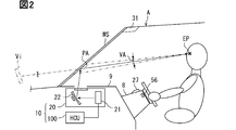
- the HUD 20 is mounted on the vehicle A as one of a plurality of in-vehicle display devices together with a meter display, a center information display, and the like.
- the HUD 20 is electrically connected to the HCU 100 and sequentially acquires video data generated by the HCU 100. Based on the video data, the HUD 20 presents various information related to the vehicle A, such as route information, sign information, and control information of each vehicle-mounted function, to the driver using the virtual image Vi.
- the HUD 20 is housed in the storage space inside the instrument panel 9 below the windshield WS.
- the HUD 20 projects the light formed as a virtual image Vi toward the projection range PA of the windshield WS.
- the light projected on the windshield WS is reflected toward the driver's seat side in the projection range PA and is perceived by the driver.
- the driver visually recognizes the display in which the virtual image Vi is superimposed on the foreground seen through the projection range PA.
- the HUD 20 includes a projector 21 and a magnifying optical system 22.
- the projector 21 has an LCD (Liquid Crystal Display) panel and a backlight.
- the projector 21 is fixed to the housing of the HUD 20 with the display surface of the LCD panel facing the magnifying optical system 22.
- the projector 21 displays each frame image of video data on the display surface of the LCD panel, and transmits and illuminates the display surface with a backlight to emit light formed as a virtual image Vi toward the magnifying optical system 22.
- the magnifying optical system 22 is configured to include at least one concave mirror in which a metal such as aluminum is vapor-deposited on the surface of a base material made of synthetic resin or glass.
- the magnifying optical system 22 projects the light emitted from the projector 21 onto the upper projection range PA while spreading it by reflection.
- the angle of view VA is set for the above HUD20.
- the angle of view VA is an angle range in which the virtual image Vi can be visually recognized when viewed from the driver's eye point EP, and is a viewing angle defined based on a virtual line connecting the eye point EP and the outer edge of the projection range PA.
- the horizontal angle of view for example, about 5 to 10 °
- the vertical angle of view for example, about 15 to 25 °
- the front range that overlaps with the projection range PA is the range within the angle of view VA.
- the HUD 20 displays the superimposed content CTs (see FIGS. 6 and 7) and the non-superimposed content CTn (see FIGS. 5 and 8) as virtual images Vi.
- Superimposed content CTs are AR display objects used for augmented reality (hereinafter referred to as “AR”) display.
- the display position of the superimposed content CTs is associated with a specific superimposed object present in the foreground, such as a road surface, a vehicle in front, a pedestrian, and a road sign.
- the superimposed content CTs are superimposed and displayed on a specific superimposed object in the foreground, and can be moved in the appearance of the driver following the superimposed object so as to be relatively fixed to the superimposed object.
- the relative positional relationship between the driver's eye point EP, the superposed object in the foreground, and the superposed content CTs is continuously maintained. Therefore, the shape of the superposed content CTs is continuously updated at a predetermined cycle according to the relative position and shape of the superposed object.
- the superimposed content CTs are displayed in a posture closer to horizontal than the non-superimposed content CTn, and have a display shape extended in the depth direction as seen from the driver, for example.
- the non-superimposed content CTn is a non-AR display object excluding the superposed content CTs among the display objects superimposed and displayed in the foreground. Unlike the superimposed content CTs, the non-superimposed content CTn is displayed superimposed on the foreground without specifying the superimposed target.
- the display position of the non-superimposed content CTn is not associated with a specific superimposition target.
- the display position of the non-superimposed content CTn is a fixed position within the projection range PA. Therefore, the non-superimposed content CTn is displayed as if it is relatively fixed to the vehicle configuration such as the windshield WS.
- the shape of the non-superimposed content CTn is substantially constant. Due to the positional relationship between the vehicle A and the superimposed target, even the non-superimposed content CTn may be superimposed and displayed on the superimposed target of the superimposed content CTs.
- the HCU 100 is an electronic control device that integrally controls the display by a plurality of in-vehicle display devices including the HUD 20 in the HMI system 10.
- the HCU 100 mainly includes a computer including a processing unit 11, a RAM 12, a storage unit 13, an input / output interface 14, and a bus connecting them.
- the processing unit 11 is hardware for arithmetic processing combined with the RAM 12.
- the processing unit 11 has a configuration including at least one arithmetic core such as a CPU (Central Processing Unit) and a GPU (Graphics Processing Unit).
- the processing unit 11 may be configured to further include an FPGA (Field-Programmable Gate Array) and an IP core having other dedicated functions.
- the RAM 12 may be configured to include a video RAM for video generation.
- the processing unit 11 executes various processes for realizing the functions of each functional unit, which will be described later, by accessing the RAM 12.
- the storage unit 13 is configured to include a non-volatile storage medium.
- Various programs (display control programs, etc.) executed by the processing unit 11 are stored in the storage unit 13.
- the HCU 100 shown in FIGS. 1 to 3 has a plurality of functional units for controlling the superimposed display of the content by the HUD 20 by executing the display control program stored in the storage unit 13 by the processing unit 11.
- the HCU 100 is constructed with functional units such as a viewpoint position specifying unit 71, a vehicle information acquisition unit 72, an outside world information acquisition unit 73, a position information acquisition unit 74, a state determination unit 75, and a display generation unit 76. ..
- the viewpoint position specifying unit 71 identifies the position of the eye point EP of the driver seated in the driver's seat based on the state information acquired from the DSM 27.
- the viewpoint position specifying unit 71 generates three-dimensional coordinates (hereinafter, “eye point coordinates”) indicating the position of the eye point EP, and sequentially provides the generated eye point coordinates to the display generation unit 76.
- the vehicle information acquisition unit 72 outputs on-operation information output to the communication bus 99 by the body ECU 55, status information of the LTC function output to the communication bus 99 by the LTC control unit, and output to the communication bus 99 by the LCA control unit 51. At least acquire LC information, etc.
- the vehicle information acquisition unit 72 sequentially provides the locus shape information included in the LC information to the display generation unit 76. In addition, the vehicle information acquisition unit 72 sequentially provides the status information of the LCA function to the state determination unit 75.
- the outside world information acquisition unit 73 acquires detection information about the peripheral range of the vehicle A, particularly the range including the destination lane Lnd (see FIG. 5 and the like) from at least one of the peripheral monitoring sensor 30 and the driving support ECU 50.
- the detection information may be information before analysis such as imaging data of the front camera 31 and measurement data of the millimeter wave radar 32, or may be analysis results obtained by recognition of the driving environment by the driving support ECU 50. ..
- the outside world information acquisition unit 73 grasps the existence of another vehicle Ab that may hinder the lane change of the own vehicle.
- the outside world information acquisition unit 73 provides the display generation unit 76 with the relative position information and the size information of the other vehicle Ab.
- the position information acquisition unit 74 acquires the latest position information and direction information about the vehicle A from the locator ECU 44 as the own vehicle position information. In addition, the position information acquisition unit 74 acquires high-precision map data of the peripheral range of the vehicle A from the locator ECU 44. The position information acquisition unit 74 may acquire high-precision map data from a probe server or the like through the DCM53. The position information acquisition unit 74 sequentially provides the acquired vehicle position information and high-precision map data to the display generation unit 76.
- the state determination unit 75 determines whether the lane change control in the LCA control unit 51 is in the execution state or the standby state based on the status information provided by the vehicle information acquisition unit 72.
- the state determination unit 75 sequentially provides the display generation unit 76 with the result of the state determination based on the status information.
- the display generation unit 76 controls the presentation of information to the driver by the HUD 20 by generating video data that is sequentially output to the HUD 20.
- the display generation unit 76 draws an original image of each content displayed as a virtual image Vi on individual frame images constituting the video data.
- the display generation unit 76 determines the drawing position and drawing shape of the original image in the frame image according to the eye point EP and each position of the overlay target. to correct.
- the superimposed content CTs are displayed at the position and shape correctly superimposed on the superimposed object when viewed from the eye point EP.
- the display generation unit 76 further has a virtual layout function and a content selection function in order to realize the above-mentioned video data generation function.
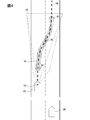
- the virtual layout function is a function of simulating the display layout of the superimposed content CTs (see FIG. 6) based on various information provided to the display generation unit 76.
- the display generation unit 76 virtualizes the current driving environment of the vehicle A based on the vehicle position information and the high-precision map data. Reproduce in space.
- the display generation unit 76 sets the own vehicle object AO at the reference position in the virtual three-dimensional space.
- the display generation unit 76 maps the road model of the shape indicated by the high-precision map data to the three-dimensional space in association with the own vehicle object AO based on the own vehicle position information.
- the display generation unit 76 sets the planned travel locus PR of the shape based on the locus shape information on the road model.
- the display generation unit 76 arranges the other vehicle object BO having a size based on the size information of the other vehicle Ab based on the relative position information of the other vehicle Ab (see FIG. 10). ..
- the display generation unit 76 sets the virtual camera position CP and the superimposition range SA in association with the own vehicle object AO.
- the virtual camera position CP is a virtual position corresponding to the driver's eye point EP.
- the display generation unit 76 sequentially corrects the virtual camera position CP with respect to the own vehicle object AO based on the latest eye point coordinates acquired by the viewpoint position specifying unit 71.
- the superimposition range SA is a range in which the virtual image Vi can be superposed and displayed. When the display generation unit 76 looks forward from the virtual camera position CP based on the virtual camera position CP and the outer edge position (coordinates) information of the projection range PA stored in advance in the storage unit 13 (see FIG. 1) or the like.
- the front range inside the projection range PA is set as the superposition range SA.
- the superimposition range SA corresponds to the angle of view VA of HUD20.
- the display generation unit 76 arranges an arrow-shaped virtual object VO that traces the planned travel locus PR on the road surface of the road model in the three-dimensional space.
- the virtual object VO is arranged so as to overlap the planned travel locus PR, and has a shape extending along the road model.
- the virtual object VO has a shape corresponding to the execution notification content CTe (see FIG. 6) described later. That is, the shape of the virtual object VO seen from the virtual camera position CP becomes the virtual image shape of the execution notification content CTe visually recognized from the eye point EP.
- the planned travel locus PR and the virtual object VO also have a curved shape that matches the road model.
- the content selection function is a function to select the content to be used for information presentation.
- the display generation unit 76 selects the content to be drawn on the video data based on the status information of the LCA function and the simulation result of the display layout.
- the display generation unit 76 properly uses the superimposed content CTs and the non-superimposed content CTn, and presents the related information of the lane change control.
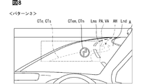
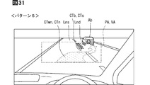
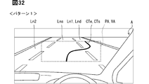
- the contents drawn by the display generation unit 76 include response notification content CTa (see FIG. 5), execution notification content CTe (see FIGS. 6 and 7), execution notification icon CTen (see FIG. 8), and standby notification content CTwn (see FIG. 8). 9 and 10) are included. Further, the content drawn by the display generation unit 76 further includes another vehicle notification icon CTb (see FIG. 10) and a timeout notification icon CTx (see FIG. 11).
- the response notification content CTa shown in FIG. 5 is a display object that notifies the driver that the input of the on operation to the direction indicator switch 56 has been accepted.
- the state in which the response notification content CTa is displayed is defined as the "pattern 0" display state.
- the display of the response notification content CTa is started based on the acquisition of the on-operation information by the vehicle information acquisition unit 72.
- the display of the response notification content CTa is continued until the environment check around the vehicle by the LCA control unit 51 is completed and the status information of the LCA function is acquired by the vehicle information acquisition unit 72.
- the response notification content CTa is a non-superimposed content CTn, and continues to maintain a predetermined shape from the start of display to the end of display.
- the response notification content CTa is drawn in a shape related to the execution notification content CTe (see FIG. 6).
- the response notification content CTa has an arrow shape extending from the own lane Lns to the destination lane Lnd.
- the arrow-shaped response notification content CTa extending from the own lane Lns in the right front direction is displayed.
- the arrow-shaped response notification content CTa extending from the own lane Lns in the left front direction is displayed. Since the response notification content CTa is the non-superimposed content CTn, the response notification content CTa may be displayed in a state where the tip portion is deviated from the destination lane Lnd due to the curvature and slope of the traveling road.
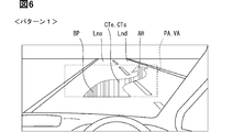
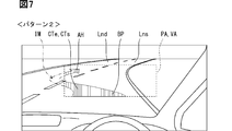
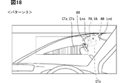
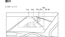
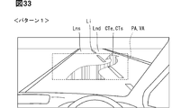
- the execution notification content CTe shown in FIGS. 6 and 7 is the superimposed content CTs indicating the execution schedule of the lane change by the LCA control unit 51, and the superimposed content CTs indicating the execution state of the lane change.
- the display of the execution notification content CTe is started when the status information indicating the execution state is acquired by the vehicle information acquisition unit 72.
- the execution notification content CTe targets both the road surfaces of the own lane Lns and the destination lane Lnd in the foreground to be superimposed, and is superimposed and displayed in a shape straddling the own lane Lns and the destination lane Lnd.
- the drawing shape of the execution notification content CTe is determined based on the simulation result of the display layout. Therefore, the execution notification content CTe has an arrow shape indicating the expected trajectory (planned traveling trajectory PR) of the vehicle A.
- the iron portion AH of the execution notification content CTe is located in the destination lane Lnd and indicates the traveling direction of the vehicle A after the lane change.
- the base end portion BP of the execution notification content CTe is located in the own lane Lns.
- the execution notification content CTe is updated to the latest shape in synchronization with the update cycle (for example, 10 ms) of the scheduled travel locus PR generated by the LCA control unit 51. As a result, the execution notification content CTe continues to be displayed while the shape is updated until the completion of the lane change control.
- the display color of the execution notification content CTe is different from the display color of the response notification content CTa and the standby notification content CTwn.
- the display brightness of the execution notification content CTe is different from each display brightness of the response notification content CTa and the standby notification content CTwn, and is set higher than these display brightness.
- the display generation unit 76 determines whether or not the execution notification content CTe is cut off from the angle of view VA based on whether or not the virtual object VO protrudes from the superposition range SA. ..
- the display generation unit 76 determines that the execution notification content CTe cannot be seen from the angle of view VA.
- the entire execution notification content CTe is displayed as a virtual image Vi.
- the state in which the entire execution notification content CTe is displayed in this way is defined as the display state of "Pattern 1".
- the execution notification content It is determined that the CTe cannot be seen from the angle of view VA.
- the execution notification content CTe for example, the intermediate portion IM (see FIG. 7 two-point difference line) is missing, and the iron portion AH and the proximal portion BP are separated from each other, resulting in a virtual image. Is displayed.
- the execution notification content CTe can present the expected trajectory of the lane change to the driver from the iron portion AH and the proximal end portion BP.
- the state in which the execution notification content CTe having a partially missing shape is displayed in this way is defined as the display state of "Pattern 2".
- the display generation unit 76 determines that the execution notification content CTe is cut off from the angle of view VA when the iron portion AH of the virtual object VO protrudes from the superposition range SA. To do.
- the cut-off of the execution notification content CTe is caused by the curve shape and slope shape of the road and the vehicle speed.
- a predetermined time is required for the LCA control unit 51 to change lanes.
- the position of the own vehicle after a predetermined time must be within the angle of view VA. As an example, if the predetermined time is about 8 seconds and the vehicle speed is 100 km / h, it is necessary to keep 222 m ahead within the angle of view VA.
- the curve shape, the gradient shape, the vehicle speed, and the like it is difficult to keep the position of the own vehicle after a predetermined time within the angle of view VA.
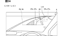
- the execution notification content CTe is cut off from the angle of view VA, the execution notification content CTe is hidden (see FIG. 8 two-point difference line). Then, the execution notification icon CTen as shown in FIG. 8 is displayed. The state in which the execution notification icon CTen is displayed in this way is defined as the display state of "Pattern 3".
- the execution notification icon CTen is content indicating the execution state of the lane change by the LCA control unit 51, similarly to the execution notification content CTe.
- the execution notification icon CTen is a display object including an arrow-shaped central image portion that bends toward the Lnd side of the destination lane and points in the traveling direction (upward), and an outer peripheral image portion that surrounds the circumference of the arrow shape in an annular shape.
- the execution notification icon CTen is displayed with substantially the same display color and display brightness as the execution notification content CTe.
- the execution notification icon CTen is a non-superimposed content CTn in which the superimposition target is not specified, and the display posture is such that the driver faces the driver.
- the execution notification icon CTen is fixedly displayed at a specific position in the projection range PA. In such a specific position, the start position of the steering control seen from the eye point EP at a specific timing, that is, the lateral acceleration may be set as the rising position.
- the execution notification icon CTen continues to be displayed while maintaining a predetermined shape until the completion of the lane change control.
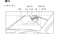
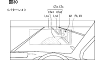
- the standby notification content CTw shown in FIGS. 9 and 10 is a non-superimposed content CTn indicating that the lane change by the LCA control unit 51 is in the standby state.
- the standby notification content CTwn is continuously displayed while maintaining a constant shape during the period when the status information indicating the waiting state for changing lanes is acquired by the vehicle information acquisition unit 72.
- the standby notification content CTwn has a shape related to the execution notification content CTe, and specifically, like the response notification content CTa, has an arrow shape extending from the own lane Lns to the destination lane Lnd.
- the left-right direction in which the standby notification content CTwn extends corresponds to the moving direction of the vehicle A in the lane change control.
- the display color and display brightness of the standby notification content CTwn may be substantially the same as the response notification content CTa, or may be different from the response notification content CTa.
- the standby notification content CTwn is superimposed and displayed on the foreground in a manner as if it were floating from the road surface.
- a shadow portion Shd that produces a floating feeling of the standby notification content CTwn is displayed.
- the shadow portion Shd is displayed with a display color similar to that of the standby notification content CTwn and with a display brightness lower than that of the standby notification content CTwn.
- the display generation unit 76 corrects the shape of the standby notification content CTwn based on whether or not the other vehicle object BO has entered the superposition range SA in the display layout simulation.
- the standby notification content CTwn having a reference shape as shown in FIG. 9 is displayed.
- the state in which the standby notification content CTwn of the reference shape is displayed in this way is defined as the display state of "Pattern 4".
- the standby notification content CTwn avoids the other vehicle Ab in the foreground and does not overlap the other vehicle Ab, as shown in FIG. Is corrected to.
- the standby notification content CTwn is transformed into a shape reduced in the vertical (front-back) direction.
- the other vehicle notification icon CTb is displayed.
- the other vehicle notification icon CTb is a superposed content CTs that notifies the driver of the existence of another vehicle Ab that is the cause of the standby state.
- the other vehicle notification icon CTb is displayed as a virtual image in a posture facing the driver, and emphasizes the other vehicle Ab in the foreground.
- the other vehicle notification icon CTb is located in the vicinity of the other vehicle Ab in the foreground, and the display position in the angle of view VA is set according to the relative position of the other vehicle Ab so as not to overlap with the standby notification content CTwn. It will be adjusted.
- the state in which the other vehicle notification icon CTb is displayed together with the standby notification content CTwn is defined as the "pattern 5" display state.
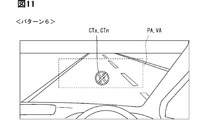
- the timeout notification icon CTx shown in FIG. 11 is a non-superimposed content CTn that notifies the driver of the cancellation of the execution of the lane change control by the LCA control unit 51.
- the time-out notification icon CTx is displayed when the standby state exceeds a predetermined upper limit time (for example, about 20 seconds) and the execution of the lane change control by the LCA control unit 51 is canceled, and the display is continued for a certain period of time.
- the drawing shape of the time-out notification icon CTx is related to the execution notification icon CTen, and the execution notification icon CTen is overlaid with an "x" indicating negation.
- the time-out notification icon CTx has a display color different from that of the execution notification icon CTen, and specifically, it is displayed in a display color such as amber that calls attention. As described above, the state in which the timeout notification icon CTx is displayed is defined as the display state of "Pattern 6".
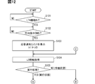
- FIGS. 3 and 5 to 11 details of the display control method for switching the display of patterns 0 to 6 related to the LCA function based on the display control program, based on the flowcharts shown in FIGS. 12 to 14. While doing so, the following will be explained.
- the display control process shown in FIGS. 12 to 14 is started based on, for example, that the power supply of the vehicle A is switched to the on state and the power supply to the HCU 100 is started.
- the LTA control unit determines whether or not the LTA function is in the ON state.
- the standby state is maintained by repeating the determination in S101.
- at least the virtual image display related to the LCA function is not performed. Then, when it is determined that the LTA function has been switched to the ON state, the process proceeds to S102.
- S102 it is determined whether or not the on operation of the lane change control is input to the direction indicator switch 56 based on whether or not the on operation information is acquired by the vehicle information acquisition unit 72.
- the standby state is maintained by repeating the determination in S102. Also at this time, at least the virtual image display related to the LCA function is not performed. Then, when it is determined that the on operation has been input to the direction indicator switch 56 by the acquisition of the on operation information, the process proceeds to S103.
- S104 LC information is acquired and the process proceeds to S105.
- S104 waits for the LCA control unit 51 to start outputting LC information.
- the response notification content CTa can be continuously displayed to indicate to the driver that the surrounding situation is normally checked.
- S105 it is determined whether the lane change is in the execution state or the standby state based on the status information of the LC information acquired in S104. If it is determined in S105 that the lane change is not in the standby state but in the execution state, the process proceeds to S106.
- S106 it is determined whether or not the entire execution notification content CTe fits within the angle of view VA based on the simulation result of the display layout. If it is determined in S106 that the entire execution notification content CTe fits within the angle of view VA, the process proceeds to S107. In S107, instead of the response notification content CTa or the standby notification content CTwn, the execution notification content CTe of the reference shape is superimposed and displayed on the road surface in the foreground, and the display control process is terminated. The display of the pattern 1 (see FIG. 6) started in S107 is continued until the completion of the lane change control while updating the superimposed shape of the execution notification content CTe.
- the process proceeds to S108.
- S108 it is further determined whether or not the iron portion AH of the execution notification content CTe fits within the angle of view VA. If it is determined in S108 that the entire iron portion AH fits within the angle of view VA, the process proceeds to S109.
- S109 the execution notification content CTe including at least the iron portion AH is superimposed and marked on the road surface in the foreground, and the display control process is terminated. The display of the pattern 2 (see FIG. 7) started in S109 is continued until the completion of the lane change control while updating the superimposed shape of the execution notification content CTe.
- the process proceeds to S110.
- the execution notification icon CTen which is the non-superimposed content CTn, is superimposed and displayed on the foreground, and the display control process is terminated.
- the execution notification content CTe is hidden.
- the display of the pattern 3 (see FIG. 8) started in S109 is also continued until the lane change control is completed.
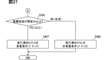
- S111 it is determined whether or not the lane change control by the LCA control unit 51 has timed out due to the continuation of the standby state.
- the LCA control unit 51 times out the received lane change control, for example, by continuing the standby state for 20 seconds or longer.
- S115 the display of the pattern 6 (see FIG. 11) including the timeout notification icon CTx is started, and the display control process is ended.
- the display of the pattern 6 started in S115 is continued for a predetermined time. By displaying the time-out notification icon CTx, the driver is notified of the time-out of the lane change control instructed to be executed.
- S111 If it is determined in S111 that the lane change control is before the timeout, the process proceeds to S112. In S112, it is determined whether or not the other vehicle Ab, which is a factor of the standby state, is located within the angle of view VA. If it is determined in S112 that the other vehicle Ab is outside the angle of view VA, the process proceeds to S113. In S113, the display of the pattern 4 (see FIG. 9) including the standby notification content CTwn of the reference shape is started, and the process returns to S104.
- the process proceeds to S114.
- the display of the pattern 5 (see FIG. 10) including the standby notification content CTwn modified so as to avoid the other vehicle Ab and the other vehicle notification icon CTb is started, and the process returns to S104.
- Each display including the standby notification content CTwn by S113 and S114 is continuously displayed during the period of the standby state. Then, the display transition from the standby notification content CTwn to the execution notification content CTe is executed by the state transition from the standby state to the execution state.
- the standby notification content CTwn is displayed.
- the standby notification content CTwn is an aspect related to the execution notification content CTe indicating the execution state of the lane change. Therefore, the standby notification content CTwn may suggest that the lane change is in the waiting state waiting for the transition to the executing state while indicating that the lane change is not in the executing state. Therefore, it is possible for the user of the vehicle A to grasp the standby state for changing lanes.
- the shape of the standby notification content CTwn is maintained constant when there is no other vehicle Ab in the angle of view VA during the period in which the standby state for changing lanes continues. According to such a display process, it is possible to avoid a situation in which the driver feels that the display fluctuation of the standby notification content CTwn in the standby state is annoying.
- the standby notification content CTwn when the other vehicle Ab exists in the angle of view VA, the standby notification content CTwn is deformed into a shape that does not overlap with the other vehicle Ab in the actual scene. Based on the above, it is possible to avoid a situation in which the standby notification content CTwn obstructs the visibility of the other vehicle Ab, making it difficult to grasp the reason for the standby state.
- the display of the response notification content CTa as the non-superimposed content CTn is started based on the acquisition of the on-operation information. Therefore, the driver can recognize that the input of the on-operation instructing the execution of the lane change has been normally received by the system side. Therefore, the driver's sense of security for automatic lane change control can be fostered.
- the response notification content CTa is a non-superimposed content CTn for which the superimposition target is not specified. According to the above, since the process of specifying the superposition target becomes unnecessary, the display of the response notification content CTa can be started quickly in response to the on operation. According to the above, the operability felt by the driver is improved.
- the LCA control unit 51 corresponds to the "lane change control unit”
- the vehicle information acquisition unit 72 corresponds to the "information acquisition unit”
- the display generation unit 76 corresponds to the "display control unit”.
- the other vehicle Ab corresponds to the "risk target”
- the HCU 100 corresponds to the "display control device”.
- the second embodiment of the present disclosure shown in FIGS. 15 to 20 is a modification of the first embodiment.
- a part of the content displayed based on the display control method shown in FIGS. 15 and 16 is different from the first embodiment.
- each display of pattern 0, pattern 3, pattern 4 and pattern 5 is different from that of the first embodiment.
- the details of the display of each pattern will be described in order.
- pattern 1, pattern 2 and pattern 6 are substantially the same as those of the first embodiment. Further, in S206 to S209 shown in FIG. 15, substantially the same processing as in S106 to S109 shown in FIG. 12 is performed. Further, in S211, S212, and S215 shown in FIG. 16, substantially the same processing as in S111, S112, and S115 shown in FIG. 13 is performed.
- the display of the pattern 0 shown in FIG. 17 is started based on the input of the on operation to the direction indicator switch 56 (see FIG. 3) as in the first embodiment (see S103 of FIG. 12).
- the response notification content CTa displayed in pattern 0 is the non-superimposed content CTn for which the superimposition target is not specified.
- the response notification content CTa is a display object including an arrow-shaped central image portion that bends toward the Lnd side of the destination lane and points in the traveling direction (upward), and an outer peripheral image portion that surrounds the circumference of the arrow shape in an annular shape.
- the response notification content CTa continues to be displayed at a predetermined position in the angle of view VA while maintaining a predetermined shape from the start of display to the end of display.
- the response notification content CTa is displayed in the substantially center of the angle of view VA (projection range PA), so that it is superimposed on the own lane Lns (or the destination lane Lnd) or the like in the foreground.
- the display generation unit 76 (see FIG. 3) is displayed when the iron portion AH is cut off from the angle of view VA. ) Is selected (see FIG. 15, S210).
- the execution notification content CTe of the pattern 3 has a shape deformed so that the iron portion AH is within the angle of view VA, and is superimposed and displayed on the road surface in the foreground.
- the execution notification content CTe of the pattern 3 is a superposed content CTs having a shape in which the tip end side of the execution notification content CTe, which is the reference shape, is shortened to within the angle of view VA.
- the iron portion AH is extended to the vicinity of the outer edge of the angle of view VA, and the direction of the destination lane Lnd is indicated by the iron portion AH.
- the superimposition target of the execution notification content CTe in the pattern 3 may include the road surface of the destination lane Lnd slightly, or may be only the road surface of the own lane Lns.
- the execution notification content CTe of the reference shape is the execution notification content CTe displayed in pattern 1 (see FIG. 6). That is, the shape of the virtual object VO (see FIG. 4) when viewed from the eye point EP (see FIG. 2) becomes the reference shape of the execution notification content CTe. More specifically, the execution notification content CTe of the mode in which the future traveling direction of the vehicle A is indicated by the iron portion AH superimposed on the road surface of the destination lane Lnd becomes the execution notification content CTe of the reference shape. On the other hand, the modified execution notification content CTe has a shape indicating the relative direction of the destination lane Lnd.
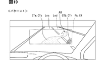
- the display of the pattern 4 shown in FIG. 19 is a display selected when the lane change is in the standby state and the other vehicle Ab (see FIG. 20) exists outside the angle of view VA (see S213 of FIG. 16). ..
- the standby notification content CTw of the reference shape and the other vehicle notification icon CTb are superimposed and displayed on the foreground.
- the standby notification content CTw is superimposed content CTs indicating a standby state for changing lanes. Similar to the execution notification content CTe (see FIG. 18), the standby notification content CTw is superimposed and displayed over both the road surfaces of the own lane Lns and the destination lane Lnd in the foreground. As an example, the standby notification content CTw has an arrow shape indicating an expected locus when it is assumed that another vehicle Ab does not exist.
- the iron part AH of the standby notification content CTw indicates the traveling direction of the own vehicle in the destination lane Lnd.
- the shape of the standby notification content CTw is updated at a predetermined cycle according to the shape of the road surface to be superimposed during the period in which the determination of the standby state continues.
- the update cycle of the shape of the standby notification content CTw is set to be about the same as the update cycle (for example, 10 ms) of the planned travel locus PR (see FIG. 4) or longer than the update cycle.
- the standby notification content CTw is content indicating the expected locus of the vehicle A when it is assumed that the vehicle A has entered the execution state and the lane change has been started.
- the standby notification content CTw is superimposed and displayed in a manner different from the execution notification content CTe (see FIG. 18). Specifically, in the standby notification content CTw, at least one of the display color and the display brightness is changed with respect to the execution notification content CTe, and the display object has a lighter color than the execution notification content CTe. As an example, the standby notification content CTw is displayed with a display brightness lower than that of the execution notification content CTe while having a higher brightness of the display color than the execution notification content CTe.
- the contour line of the standby notification content CTw is different from the contour line of the execution notification content CTe. For example, the contour line of the standby notification content CTw may be drawn in a broken line shape, and the contour line of the execution notification content CTe may be drawn in a solid line shape.
- the other vehicle notification icon CTb is a non-superimposed content CTn that notifies the driver of the existence of the other vehicle Ab that is the cause of the standby state, as in the first embodiment.
- the other vehicle notification icon CTb of the second embodiment has a ripple shape that propagates from the corner of the angle of view VA (projection range PA) toward the center.
- the display position of the other vehicle notification icon CTb corresponds to the relative position of the other vehicle Ab with respect to the own vehicle. As an example, when the other vehicle Ab is traveling on the right rear side of the own vehicle, the other vehicle notification icon CTb is displayed in the lower right corner of the projection range PA among the four corners of the projection range PA. Similarly, when the other vehicle Ab is traveling on the right front side of the own vehicle, the other vehicle notification icon CTb is displayed in the upper right corner of the projection range PA.
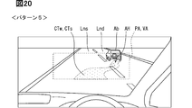
- the display of the pattern 5 shown in FIG. 20 is a display selected when the lane change is in the standby state and the other vehicle Ab is in the angle of view VA (see FIG. 16S214).
- the display of the pattern 5 includes the standby notification content CTw having a deformed shape.
- the standby notification content CTw has a portion of the standby notification content CTw (see FIG. 19) that serves as a reference shape so as not to overlap with another vehicle Ab that is visually recognized through the angle of view VA (projection range PA).
- the shape is such that the position of the AH is moved to the front side of the other vehicle Ab.
- the standby notification content CTw is superimposed and displayed across both the road surfaces of the own lane Lns and the destination lane Lnd.
- the shape of the standby notification content CTw is updated at a predetermined cycle in accordance with the shape of the road surface seen from the eye point EP (see FIG. 2) during the period in which the determination of the standby state continues.
- the standby notification content CTw when the lane change by the LCA control unit 51 is in the standby state, the standby notification content CTw is superimposed and displayed on the road surface.
- the standby notification content CTw is displayed in a mode different from the execution notification content CTe indicating the execution state of the lane change. Therefore, the standby notification content CTwn may suggest that the lane change is in the waiting state waiting for the transition to the executing state while indicating that the lane change is not in the executing state. According to the above, it is possible to make the user of the vehicle grasp the standby state of the lane change.
- the shape of the standby notification content CTw is updated according to the shape of the road surface to be superimposed during the period in which the waiting state for changing lanes continues. Therefore, the standby notification content CTw can indicate to the driver that the system related to the lane change control continues to correctly recognize the surrounding environment.
- the standby notification content CTw showing the expected trajectory of the vehicle A is superimposed and displayed on the road surface. Therefore, even if the transition from the standby state to the execution state occurs, the driver can easily keep track of the trajectory of the vehicle A to change lanes during the standby state. Based on the above, a sense of security for the driver can be fostered.
- the standby notification content CTwn is transformed into a shape that does not overlap with the other vehicle Ab in the actual scene. Based on the above, it is unlikely that the standby notification content CTw will interfere with the visibility of the other vehicle Ab, which is the reason for the standby state.
- the driver can recognize that the input of the on operation has been accepted by the system side by starting the display of the response notification content CTa based on the acquisition of the on operation information. According to the above, it becomes easy to foster a sense of security for the driver.
- the response notification content CTa is set to the non-superimposed content CTn, the process of grasping the superimposed target can be omitted, so that the display of the response notification content CTa can be started quickly with respect to the on operation. As a result, the operability felt by the driver is improved.
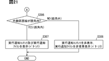
- the third embodiment of the present disclosure shown in FIGS. 21 to 26 is another modification of the first embodiment.
- the cut-off determination determination logic used in S306 is different from that of the first embodiment.
- the display of each pattern based on S307, S308, S311 and S312 is different from that of the first and second embodiments.
- the indications of pattern 0 and pattern 6 in the third embodiment are substantially the same as those in the second embodiment. Further, in the third embodiment, the display of the pattern 2 is not set. In addition, in S309, S310, and S313 shown in FIG. 22, substantially the same processing as in S111, S112, and S115 shown in FIG. 15 is performed.
- the display generation unit 76 performs a cut-off determination for the angle of view VA of the execution notification content CTe in the process of S306.
- the relative positions of the lane markings on both sides of the destination lane Lnd which is the destination for changing lanes, are grasped. Then, based on the simulation result of the display layout, it is determined whether or not the outer lane marking Lo on the side far from the vehicle A deviates from the angle of view VA.
- the display of the pattern 1 shown in FIG. 23 includes the execution notification content CTe of the reference shape and the execution notification icon CTen.
- the execution notification content CTe is the superposed content CTs in which the road surface in the foreground is targeted for superimposition and indicates the implementation schedule of the lane change.
- the execution notification content CTe of the third embodiment does not have an arrow shape.
- the execution notification content CTe may be displayed in a blinking state, for example.
- the execution notification content CTe is the road surface that can be seen from the eye point EP (see FIG. 2) until the lane change control is completed in accordance with the update of the scheduled travel locus PR (see FIG. 4) in the LCA control unit 51 (see FIG. 3).
- the display shape is updated according to the shape.
- the execution notification icon CTen is a non-superimposed content CTn for which the superimposition target is not specified.
- the execution notification icon CTen is displayed, for example, approximately in the center of the angle of view VA (projection range PA), and is mainly superimposed on the own lane Lns.
- the execution notification icon CTen indicates the execution state of the lane change, similarly to the execution notification content CTe.
- the execution notification icon CTen is a display object including an arrow-shaped central image portion and an annular outer peripheral image portion, as in the first embodiment.
- the execution notification icon CTen is displayed with substantially the same display color and display brightness as the adjacent execution notification content CTe.
- the execution notification icon CTen continues to be displayed while maintaining a predetermined shape until the completion of the lane change control.
- the display position of the execution notification icon CTen may be shifted in the vertical direction according to the start position of the lane change. Further, the execution notification icon CTe may be displayed blinking in the same manner as the execution notification content CTe.
- the execution notification content CTe (see FIG. 23) is in a hidden state.
- the display of the pattern 3 includes the execution notification icon CTen which is substantially the same as that displayed in the pattern 1.
- the display position of the execution notification icon CTen is a position shifted from the center of the angle of view VA (projection range PA) to the Lnd side of the destination lane.
- the display of the pattern 4 shown in FIG. 25 includes the standby notification content CTw having a reference shape and the standby notification icon CTwi (see FIG. 22S311).
- the standby notification content CTw indicates that the road surface of the destination lane Lnd is subject to superposition, and that the lane change scheduled by the LCA control unit 51 (see FIG. 3) is in the standby state.
- the standby notification content CTw is superimposed content CTs that are superimposed and displayed on the road surface of the destination lane Lnd in a mode different from the execution notification content CTe (see FIG. 23).
- the standby notification content CTw is displayed in a display color and display brightness different from the execution notification content CTe.
- the standby notification content CTw may be displayed in a display color such as yellow or amber that calls attention.
- the display shape of the standby notification content CTw is updated according to the road surface shape seen from the eye point EP (see FIG. 2) during the period in which the determination of the standby state continues.
- the standby notification content CTw indicates to the driver that movement to the destination lane Lnd is prohibited by painting the road surface of the destination lane Lnd with a display color that calls attention.
- the standby notification content CTw may be displayed in such a manner that the road surface of the destination lane Lnd is inclined toward the own lane Lns side to indicate to the driver that the vehicle cannot immediately move to the destination lane Lnd. Good.
- the standby notification icon CTwi is a non-superimposed content CTn in which the superimposition target is not specified.
- the standby notification icon CTwi has substantially the same shape as the execution notification icon CTen (see FIG. 23), and is displayed substantially in the center of the angle of view VA (projection range PA).
- the standby notification icon CTwi indicates that the lane change execution command is valid in cooperation with the standby notification content CTw, but it is difficult to execute it immediately.
- the standby notification icon CTwi may be displayed with substantially the same display color and display brightness as either the execution notification icon CTen or the standby notification content CTw.
- the standby notification icon CTwi continues to be displayed while maintaining a predetermined shape and display position during the period during which the determination of the standby state continues.
- the display of the pattern 5 shown in FIG. 26 includes a standby notification icon CTwi and a modified standby notification content CTw (see FIG. 22S 312).
- the standby notification icon CTwi in pattern 5 is substantially the same as the standby notification icon CTwi in pattern 4.
- the standby notification content CTw reduces the standby notification content CTw (see FIG. 25) of the pattern 4, which is the reference shape, in the vertical direction to the front side of the other vehicle Ab so as not to interfere with the visibility of the other vehicle Ab. It is said to be a shape.
- the third embodiment when the lane change is in the standby state, the standby notification content CTw is superimposed and displayed on the road surface in the foreground in a manner different from the execution notification content CTe.
- the third embodiment also has the same effect as that of the second embodiment, and the standby notification content CTw can make the user of the vehicle A grasp the waiting state of the lane change.
- the fourth embodiment of the present disclosure shown in FIGS. 27 to 31 is still another modification of the first embodiment.
- the determination logic for determining the cutoff used in S406 is different from each of the above embodiments.
- the display of each pattern based on S407, S411 and S412 is different from each of the above-described embodiments.
- the details of the display control method (see FIGS. 27 and 28) in the fourth embodiment and the details of the display of each pattern (see FIGS. 29 to 31) in the fourth embodiment will be described in order.
- the indications of pattern 0 and pattern 6 in the fourth embodiment are substantially the same as those in the first embodiment.
- the display of pattern 3 of the fourth embodiment is the same as that of the third embodiment.
- substantially the same processing as in S308 shown in FIG. 21 and S309, S310, and S313 shown in FIG. 22 is performed.
- the display generation unit 76 performs a cut-off determination for the angle of view VA of the execution notification content CTe in the process of S406.
- the overlapping area Aol (see the range of the two-point difference line in FIG. 28) that overlaps with the destination lane Lnd, which is the destination for changing lanes, is found. Calculate the area ratio to occupy. Then, it is determined whether or not the area ratio occupied by the overlapping region Aol exceeds a predetermined threshold value th.
- the display of pattern 1 shown in FIG. 29 includes the execution notification content CTe.
- the execution notification content CTe of the third embodiment does not have an arrow shape unlike the first embodiment and the like.
- the execution notification content CTe is strip-shaped superimposed content CTs showing the expected locus of the vehicle A, and extends along the planned traveling locus PR generated by the LCA control unit 51.
- the tip portion of the execution notification content CTe is superimposed on the road surface of the destination lane Lnd.
- the base end portion of the execution notification content CTe is superimposed on the road surface of the own lane Lns.
- the display of the pattern 4 shown in FIG. 30 includes two standby notification contents CTw (see FIG. 28 S411). Both of the two standby notification contents CTw are superposed content CTs for which the road surface in the foreground is superposed, and are displayed in a mode different from the execution notification content CTe of pattern 1 (see FIG. 29).
- the two standby notification contents CTw indicate that the lane change scheduled by the LCA control unit 51 (see FIG. 3) is in the standby state.
- first standby notification content CTw1 one of the two standby notification contents CTw
- second standby notification content CTw2 is referred to as "second standby notification content CTw2".
- the first standby notification content CTw1 is substantially the same content as the standby notification content CTw (see FIG. 19) of the second embodiment.
- the first standby notification content CTw1 has an arrow shape that is superimposed and displayed across both road surfaces of the own lane Lns and the destination lane Lnd, and shows an expected locus when it is assumed that no other vehicle Ab exists.
- the first standby notification content CTw1 is differentiated from the execution notification content CTe (see FIG. 29) by having the iron portion AH.
- the second standby notification content CTw2 is substantially the same content as the standby notification content CTw (see FIG. 25) of the third embodiment, and the road surface of the destination lane Lnd seems to be inclined toward the own lane Lns side. I'm showing you.
- the first standby notification content CTw1 is superimposed on the second standby notification content CTw2.
- the second standby notification content CTw2 is displayed in a display color and display brightness different from that of the first standby notification content CTw1 so as to be easily distinguished from the first standby notification content CTw1.
- the display generation unit 76 changes the display color and contour line of the first standby notification content CTw1 from the own vehicle side toward the traveling direction when the control state transitions from the standby state to the execution state. Display a wipe-like animation. By such an animation, the first standby notification content CTw1 is changed to the execution notification content CTe while eliminating the iron portion AH. Further, the display generation unit 76 terminates the display of the second standby notification content CTw2 in parallel with the display change of the first standby notification content CTw1.
- the display of the pattern 5 shown in FIG. 31 includes the standby notification content CTwn and the other vehicle notification icon CTb.
- the standby notification content CTwn is a non-superimposed content CTn having an arrow shape extending from the own lane Lns to the destination lane Lnd, similarly to the standby notification content CTwn (see FIG. 10) of the first embodiment.
- the standby notification content CTwn is displayed in a manner as if it were attached to the road surface.
- the standby notification content CTwn is considered to be an aspect related to the execution notification content CTe of pattern 1 (see FIG. 29), and specifically, like the execution notification content CTe, the road surface so as to show the expected trajectory of the vehicle A. It has a display shape that extends upward.
- the shape of the standby notification content CTwn is corrected so that the iron portion AH is located in front of the other vehicle Ab and does not overlap with the other vehicle Ab in the foreground.
- the other vehicle notification icon CTb is substantially the same as the other vehicle notification icon CTb displayed in pattern 5 (see FIG. 10) of the first embodiment.
- the standby notification contents CTw1 and CTw2 are in a mode different from the execution notification content CTe. , Overlaid on the road surface in the foreground.
- the fourth embodiment also has the same effect as that of the second embodiment, and the standby notification contents CTw1 and CTw2 can make the user of the vehicle A grasp the waiting state of the lane change.
- the standby notification content CTwn in the mode related to the execution notification content CTe is set as the non-superimposed content CTn. Is displayed.
- the fourth embodiment also has the same effect as that of the first embodiment, and the standby notification content CTwn can make the user of the vehicle A grasp the waiting state of the lane change.
- the determination logic for the cut-off determination used in the display generation unit is different from the determination logic for the third embodiment (see FIG. 21S306).
- the display generation unit of the first modification determines whether or not the execution notification content CTe is cut off from the angle of view VA based on the moving direction of the vehicle A in the lane change.
- the driver's seat and the passenger's seat are arranged so as to line up in the left-right direction.
- the driver's seat is located on the right side of the passenger's seat. Therefore, the front overlapping range visually recognized through the projection range PA in front of the driver is wider on the right front side than on the left front side. Therefore, when the adjacent lane Ln1 on the right side on the driver's seat side becomes the destination lane Lnd due to the lane change, the display generation unit considers that the execution notification content CTe cannot be seen from the angle of view VA.
- the display generation unit considers that the execution notification content CTe is cut off from the angle of view VA. According to such a determination, the calculation resource required for the cut-off determination can be significantly reduced.
- the display generator In the case of a vehicle with a left steering wheel, if the adjacent lane on the left side is the destination lane, the display generator considers that the execution notification content cannot be seen from the angle of view. On the other hand, when the adjacent lane on the right side becomes the destination lane for changing lanes, the display generation unit considers that the execution notification content is cut off from the angle of view.
- the execution notification content CTe used for displaying the pattern 1 in the modification 1 is a superposed content CTs showing the expected trajectory of the vehicle A due to the shape extending in a curved linear shape.
- the execution notification content CTe is drawn along the planned travel locus PR (see FIG. 4), and is superimposed and displayed across both the road surfaces of the own lane Lns and the destination lane Lnd.
- the determination logic of the cut-off determination used in the display generation unit is different from that of the above-described embodiment, as in the modified example 1.
- one of the lane markings on both sides of the moving destination lane Lnd that is, the inner lane marking Li between the own lane Lns and the moving destination lane Lnd, has an angle of view VA. If it deviates from, it is determined that the execution notification content CTe is cut off from the angle of view VA.
- the display generation unit of the modification 3 of the above embodiment determines that the execution notification content is cut off from the angle of view when any one of the curvature, the gradient, and the vehicle speed of the curve exceeds each threshold value corresponding to each value. To do. Further, the display generation unit of the modified example 4 of the above embodiment uses a function including the curvature, the gradient, and the vehicle speed of the curve as parameters to determine whether or not the execution notification content CTe is cut off from the angle of view VA. Further, the display generation unit of the modification 5 calculates the actual road surface area of the destination lane included in the angle of view VA, and determines that the execution notification content is cut off from the angle of view when the road surface area is less than a predetermined value. .. Further, it may be determined that the execution notification content CTe is cut off based on whether or not the main part different from the iron part AH is in the angle of view VA. As described above, the specific determination logic for the cut-off determination may be changed as appropriate.
- the shape of the execution notification content CTe included in the display of the pattern 3 is different from that of the second embodiment.
- the modified execution notification content CTe indicates the traveling direction of the vehicle A by the iron portion AH. At this time, the direction indicated by the iron portion AH does not match the moving direction when changing lanes.
- the execution notification content CTe may be in a mode such as pointing to a lane change completion point in the destination lane Lnd.
- the execution notification icon included in the display of the patterns 1 and 3 is superimposed and displayed on the road surface in the foreground as the superimposed content.
- the execution notification icon of the modification 7 is set as a superposition target at a position on the road surface of the own lane where steering control for changing lanes is started. Therefore, the execution notification icon can indicate to the driver the rising position of the lateral acceleration.
- the standby notification content is not transformed into a shape that does not overlap with the risk target.
- the presentation of the standby notification content CTw (see FIGS. 10 and 20 and the like) indicating the expected locus is stopped in the display of the pattern 5.
- the content in the standby state when there is a risk target different from other vehicles, specifically, a high risk target having a large relative speed with the own vehicle such as a falling object on the road surface, the content in the standby state. The display of is stopped. As described above, the visibility of the high-risk target by the driver is not hindered by the content.
- the execution notification content that was cut off from the angle of view was hidden.
- the display of the execution notification content in the cut-out state may be continued together with the non-superimposed content.
- the on operation for activating the LCA function may be input to an input unit different from the direction indicator switch.
- updating the content shape to follow the shape of the road surface may be omitted.
- the display of the response notification content may be omitted.
- the display generation unit performs a cut-off determination for the standby notification content.
- the display generation unit determines that the standby notification content cannot be seen from the angle of view, the display generation unit superimposes and displays the standby notification content indicating the expected trajectory on the road surface.
- the display generation unit determines that the standby notification content is cut off from the angle of view, the display generation unit displays the standby notification icon, which is non-superimposed content, instead of the standby notification content.
- the display generation unit may transform the standby notification content so that it fits within the angle of view based on the cut-out determination, or even if the standby notification content is hidden from the standby notification content and the standby notification icon. Good.
- the standby notification content corresponds to the “scheduled notification content” indicating the implementation schedule of the lane change.
- the execution notification content and the standby notification content as AR display objects are superimposed and displayed on the road surface in different modes from each other.
- At least one of the static elements such as the display color, the display brightness, the display shape, and the display size of the execution notification content and the standby notification content may differ to the extent that they can be distinguished by the driver.
- the execution notification content and the standby notification content may differ to such an extent that at least one of the dynamic elements such as the presence / absence of blinking, the cycle of blinking, the presence / absence of animation, and the operation of animation can be distinguished by the driver.
- the execution notification content and the standby notification content can be regarded as different modes.
- the standby notification content as non-superimposed content is displayed in a manner related to the execution notification content.
- Such standby notification content may be common to execution notification content to the extent that at least one of static elements such as display color, display brightness, display shape, and display size can be linked by the driver.
- the standby notification content may be associated with the execution notification content by including an image element common to the execution notification content, such as a main body portion to be extended and a characteristic main part.
- the driving scene in which the information presentation is illustrated in the explanation of the above embodiment and the modified example is an example.
- the HCU can present information in combination with non-superimposed content and superposed content in a driving scene different from the above. Further, the shape, display position, display color, display brightness, presence / absence of animation, etc. of each content may be changed as appropriate, and may be changed according to, for example, the preference of the driver.
- the HCU of the above embodiment uses the position information of the eye point detected by the DSM so that the superimposed content is superimposed on the superimposed object without deviation when viewed from the driver, and the virtual image light imaged as the superimposed content.
- the projected shape and projected position were sequentially controlled.
- the HCU of the modified example 11 of the above embodiment uses the setting information of the center of the reference eye point set in advance without using the detection information of the DSM, and the projected shape of the virtual image light imaged as the superimposed content and the projection shape of the virtual image light. Control the projection position.
- the projector 21 of the HUD 20 of the modified example 12 is provided with an EL (Electroluminescence) panel instead of the LCD panel and the backlight. Further, instead of the EL panel, a projector using a display such as a plasma display panel, a cathode ray tube and an LED can be adopted for the HUD 20.
- EL Electrode
- the HUD 20 of the modified example 13 is provided with a laser module (hereinafter referred to as “LSM”) and a screen instead of the LCD and the backlight.
- LSM includes, for example, a laser light source, a MEMS (Micro Electro Mechanical Systems) scanner, and the like.
- the screen is, for example, a micromirror array or a microlens array.
- a display image is drawn on the screen by scanning the laser beam emitted from the LSM.
- the HUD 20 projects the display image drawn on the screen onto the windshield by the magnifying optical element, and displays the virtual image Vi in the air.
- the HUD 20 of the modified example 14 is provided with a DLP (Digital Light Processing, registered trademark) projector.
- a DLP projector has a digital mirror device (hereinafter, "DMD") provided with a large number of micromirrors, and a projection light source that projects light toward the DMD.
- the DLP projector draws a display image on the screen under the control of linking the DMD and the projection light source.
- a projector using LCOS Liquid Crystal On Silicon
- a holographic optical element is adopted as one of the optical systems for displaying the virtual image Vi in the air.
- the HCU and the HUD are integrally configured. That is, the HUD control circuit of the modified example 16 is equipped with the HCU processing function.
- each function provided by the HCU can be provided by the software and the hardware that executes the software, the hardware only, the hardware only, or a combination thereof. Further, when such a function is provided by an electronic circuit as hardware, each function can also be provided by a digital circuit including a large number of logic circuits or an analog circuit.
- the form of the storage medium for storing the program or the like that can realize the above display control method may be changed as appropriate.
- the storage medium is not limited to the configuration provided on the circuit board, and may be provided in the form of a memory card or the like, inserted into the slot portion, and electrically connected to the control circuit of the HCU. ..
- the storage medium may be an optical disk and a hard disk drive as a copy base of the program to the HCU.
- the vehicle equipped with the HMI system is not limited to a general private car, but may be a car rental vehicle, a manned taxi vehicle, a ride sharing vehicle, a freight vehicle, a bus, or the like. Further, the HMI system and the HCU may be mounted on a vehicle dedicated to unmanned driving used for mobility services. Further, the vehicle equipped with the HMI system may be a right-hand steering vehicle or a left-hand steering vehicle. Further, the display form of each content is appropriately optimized according to the steering wheel position of the vehicle and the like.
- control unit and its method described in the present disclosure may be realized by a dedicated computer constituting a processor programmed to execute one or a plurality of functions embodied by a computer program.
- the apparatus and method thereof described in the present disclosure may be realized by a dedicated hardware logic circuit.
- the apparatus and method thereof described in the present disclosure may be realized by one or more dedicated computers configured by a combination of a processor that executes a computer program and one or more hardware logic circuits.
- the computer program may be stored in a computer-readable non-transitional tangible recording medium as an instruction executed by the computer.
Landscapes
- Engineering & Computer Science (AREA)
- Remote Sensing (AREA)
- Radar, Positioning & Navigation (AREA)
- Physics & Mathematics (AREA)
- Automation & Control Theory (AREA)
- General Physics & Mathematics (AREA)
- Mechanical Engineering (AREA)
- Transportation (AREA)
- Combustion & Propulsion (AREA)
- Chemical & Material Sciences (AREA)
- Optics & Photonics (AREA)
- Traffic Control Systems (AREA)
- Navigation (AREA)
- Instrument Panels (AREA)
Priority Applications (1)
| Application Number | Priority Date | Filing Date | Title |
|---|---|---|---|
| US17/489,185 US20220018678A1 (en) | 2019-04-01 | 2021-09-29 | Display control device and non-transitory computer-readable storage medium for display control on head-up display |
Applications Claiming Priority (2)
| Application Number | Priority Date | Filing Date | Title |
|---|---|---|---|
| JP2019069985A JP7059975B2 (ja) | 2019-04-01 | 2019-04-01 | 表示制御装置及び表示制御プログラム |
| JP2019-069985 | 2019-04-01 |
Related Child Applications (1)
| Application Number | Title | Priority Date | Filing Date |
|---|---|---|---|
| US17/489,185 Continuation US20220018678A1 (en) | 2019-04-01 | 2021-09-29 | Display control device and non-transitory computer-readable storage medium for display control on head-up display |
Publications (1)
| Publication Number | Publication Date |
|---|---|
| WO2020203066A1 true WO2020203066A1 (ja) | 2020-10-08 |
Family
ID=72668934
Family Applications (1)
| Application Number | Title | Priority Date | Filing Date |
|---|---|---|---|
| PCT/JP2020/009941 Ceased WO2020203066A1 (ja) | 2019-04-01 | 2020-03-09 | 表示制御装置及び表示制御プログラム |
Country Status (3)
| Country | Link |
|---|---|
| US (1) | US20220018678A1 (enExample) |
| JP (1) | JP7059975B2 (enExample) |
| WO (1) | WO2020203066A1 (enExample) |
Families Citing this family (4)
| Publication number | Priority date | Publication date | Assignee | Title |
|---|---|---|---|---|
| JP7302702B2 (ja) * | 2019-04-01 | 2023-07-04 | 株式会社デンソー | 表示制御装置及び表示制御プログラム |
| JP2024086476A (ja) * | 2022-12-16 | 2024-06-27 | トヨタ自動車株式会社 | 車両用表示制御装置、車両用表示制御方法及び車両用表示制御プログラム。 |
| DE102023208702A1 (de) | 2023-09-08 | 2025-03-13 | Volkswagen Aktiengesellschaft | Verfahren zur Anzeige eines Spurwechselvorgangs, Computerprogrammprodukt, sowie Fahrzeug |
| CN120558261A (zh) * | 2025-06-30 | 2025-08-29 | 广州小鹏汽车科技有限公司 | 车辆增强现实导航方法、增强现实抬头显示装置及车辆 |
Citations (6)
| Publication number | Priority date | Publication date | Assignee | Title |
|---|---|---|---|---|
| JP2017074918A (ja) * | 2015-10-16 | 2017-04-20 | 株式会社デンソー | 報知管理装置及び報知管理方法 |
| WO2017081919A1 (ja) * | 2015-11-09 | 2017-05-18 | 株式会社デンソー | 提示制御装置及び提示制御方法 |
| JP6387369B2 (ja) * | 2016-05-23 | 2018-09-05 | 本田技研工業株式会社 | 走行制御装置 |
| WO2019021458A1 (ja) * | 2017-07-28 | 2019-01-31 | 日産自動車株式会社 | 周囲状況の表示方法及び表示装置 |
| JP2019036086A (ja) * | 2017-08-14 | 2019-03-07 | 本田技研工業株式会社 | 車両制御システムおよび車両制御方法 |
| JP2019174459A (ja) * | 2018-03-29 | 2019-10-10 | 株式会社リコー | 制御装置、表示装置、移動体、制御方法、及びプログラム |
-
2019
- 2019-04-01 JP JP2019069985A patent/JP7059975B2/ja active Active
-
2020
- 2020-03-09 WO PCT/JP2020/009941 patent/WO2020203066A1/ja not_active Ceased
-
2021
- 2021-09-29 US US17/489,185 patent/US20220018678A1/en not_active Abandoned
Patent Citations (6)
| Publication number | Priority date | Publication date | Assignee | Title |
|---|---|---|---|---|
| JP2017074918A (ja) * | 2015-10-16 | 2017-04-20 | 株式会社デンソー | 報知管理装置及び報知管理方法 |
| WO2017081919A1 (ja) * | 2015-11-09 | 2017-05-18 | 株式会社デンソー | 提示制御装置及び提示制御方法 |
| JP6387369B2 (ja) * | 2016-05-23 | 2018-09-05 | 本田技研工業株式会社 | 走行制御装置 |
| WO2019021458A1 (ja) * | 2017-07-28 | 2019-01-31 | 日産自動車株式会社 | 周囲状況の表示方法及び表示装置 |
| JP2019036086A (ja) * | 2017-08-14 | 2019-03-07 | 本田技研工業株式会社 | 車両制御システムおよび車両制御方法 |
| JP2019174459A (ja) * | 2018-03-29 | 2019-10-10 | 株式会社リコー | 制御装置、表示装置、移動体、制御方法、及びプログラム |
Also Published As
| Publication number | Publication date |
|---|---|
| JP2020168892A (ja) | 2020-10-15 |
| US20220018678A1 (en) | 2022-01-20 |
| JP7059975B2 (ja) | 2022-04-26 |
Similar Documents
| Publication | Publication Date | Title |
|---|---|---|
| JP7464096B2 (ja) | 表示制御装置及び表示制御プログラム | |
| JP7338735B2 (ja) | 表示制御装置及び表示制御プログラム | |
| US11850940B2 (en) | Display control device and non-transitory computer-readable storage medium for display control on head-up display | |
| JP2022179574A (ja) | 表示制御装置及び表示制御プログラム | |
| JP7215466B2 (ja) | 表示制御装置及び表示制御プログラム | |
| WO2021039198A1 (ja) | 表示制御装置及び表示制御プログラム | |
| JP7173078B2 (ja) | 表示制御装置及び表示制御プログラム | |
| WO2020208989A1 (ja) | 表示制御装置及び表示制御プログラム | |
| JP7059975B2 (ja) | 表示制御装置及び表示制御プログラム | |
| JP2021006805A (ja) | 表示制御装置及び表示制御プログラム | |
| WO2020225990A1 (ja) | 表示制御装置及び表示制御プログラム | |
| JP7127565B2 (ja) | 表示制御装置及び表示制御プログラム | |
| JP7243660B2 (ja) | 表示制御装置及び表示制御プログラム | |
| JP7255429B2 (ja) | 表示制御装置および表示制御プログラム | |
| JP7318431B2 (ja) | 表示制御装置及び表示制御プログラム | |
| JP7293854B2 (ja) | 表示制御装置及び表示制御プログラム | |
| JP7092158B2 (ja) | 表示制御装置及び表示制御プログラム | |
| JP7063345B2 (ja) | 表示制御装置及び表示制御プログラム | |
| JP2021037895A (ja) | 表示制御システム、表示制御装置、および表示制御プログラム | |
| JP7259802B2 (ja) | 表示制御装置、表示制御プログラム及び車載システム | |
| JP7302702B2 (ja) | 表示制御装置及び表示制御プログラム | |
| JP7111121B2 (ja) | 表示制御装置及び表示制御プログラム | |
| JP2021066197A (ja) | 表示制御装置、表示制御プログラム及び車載システム | |
| JP2021060808A (ja) | 表示制御システム及び表示制御プログラム | |
| JP7188271B2 (ja) | 表示制御装置及び表示制御プログラム |
Legal Events
| Date | Code | Title | Description |
|---|---|---|---|
| 121 | Ep: the epo has been informed by wipo that ep was designated in this application |
Ref document number: 20785383 Country of ref document: EP Kind code of ref document: A1 |
|
| NENP | Non-entry into the national phase |
Ref country code: DE |
|
| 122 | Ep: pct application non-entry in european phase |
Ref document number: 20785383 Country of ref document: EP Kind code of ref document: A1 |