WO2020196504A1 - 圧縮機システム - Google Patents
圧縮機システム Download PDFInfo
- Publication number
- WO2020196504A1 WO2020196504A1 PCT/JP2020/012977 JP2020012977W WO2020196504A1 WO 2020196504 A1 WO2020196504 A1 WO 2020196504A1 JP 2020012977 W JP2020012977 W JP 2020012977W WO 2020196504 A1 WO2020196504 A1 WO 2020196504A1
- Authority
- WO
- WIPO (PCT)
- Prior art keywords
- region
- working fluid
- upstream
- physical quantity
- inlet guide
- Prior art date
- Legal status (The legal status is an assumption and is not a legal conclusion. Google has not performed a legal analysis and makes no representation as to the accuracy of the status listed.)
- Ceased
Links
Images





Classifications
-
- F—MECHANICAL ENGINEERING; LIGHTING; HEATING; WEAPONS; BLASTING
- F04—POSITIVE - DISPLACEMENT MACHINES FOR LIQUIDS; PUMPS FOR LIQUIDS OR ELASTIC FLUIDS
- F04D—NON-POSITIVE-DISPLACEMENT PUMPS
- F04D29/00—Details, component parts, or accessories
- F04D29/66—Combating cavitation, whirls, noise, vibration or the like; Balancing
- F04D29/661—Combating cavitation, whirls, noise, vibration or the like; Balancing especially adapted for elastic fluid pumps
-
- F—MECHANICAL ENGINEERING; LIGHTING; HEATING; WEAPONS; BLASTING
- F04—POSITIVE - DISPLACEMENT MACHINES FOR LIQUIDS; PUMPS FOR LIQUIDS OR ELASTIC FLUIDS
- F04D—NON-POSITIVE-DISPLACEMENT PUMPS
- F04D17/00—Radial-flow pumps, e.g. centrifugal pumps; Helico-centrifugal pumps
- F04D17/08—Centrifugal pumps
- F04D17/10—Centrifugal pumps for compressing or evacuating
- F04D17/12—Multi-stage pumps
-
- F—MECHANICAL ENGINEERING; LIGHTING; HEATING; WEAPONS; BLASTING
- F04—POSITIVE - DISPLACEMENT MACHINES FOR LIQUIDS; PUMPS FOR LIQUIDS OR ELASTIC FLUIDS
- F04D—NON-POSITIVE-DISPLACEMENT PUMPS
- F04D19/00—Axial-flow pumps
- F04D19/02—Multi-stage pumps
-
- F—MECHANICAL ENGINEERING; LIGHTING; HEATING; WEAPONS; BLASTING
- F04—POSITIVE - DISPLACEMENT MACHINES FOR LIQUIDS; PUMPS FOR LIQUIDS OR ELASTIC FLUIDS
- F04D—NON-POSITIVE-DISPLACEMENT PUMPS
- F04D27/00—Control, e.g. regulation, of pumps, pumping installations or pumping systems specially adapted for elastic fluids
- F04D27/001—Testing thereof; Determination or simulation of flow characteristics; Stall or surge detection, e.g. condition monitoring
-
- F—MECHANICAL ENGINEERING; LIGHTING; HEATING; WEAPONS; BLASTING
- F04—POSITIVE - DISPLACEMENT MACHINES FOR LIQUIDS; PUMPS FOR LIQUIDS OR ELASTIC FLUIDS
- F04D—NON-POSITIVE-DISPLACEMENT PUMPS
- F04D27/00—Control, e.g. regulation, of pumps, pumping installations or pumping systems specially adapted for elastic fluids
- F04D27/02—Surge control
- F04D27/0207—Surge control by bleeding, bypassing or recycling fluids
- F04D27/0223—Control schemes therefor
-
- F—MECHANICAL ENGINEERING; LIGHTING; HEATING; WEAPONS; BLASTING
- F04—POSITIVE - DISPLACEMENT MACHINES FOR LIQUIDS; PUMPS FOR LIQUIDS OR ELASTIC FLUIDS
- F04D—NON-POSITIVE-DISPLACEMENT PUMPS
- F04D27/00—Control, e.g. regulation, of pumps, pumping installations or pumping systems specially adapted for elastic fluids
- F04D27/02—Surge control
- F04D27/0246—Surge control by varying geometry within the pumps, e.g. by adjusting vanes
-
- F—MECHANICAL ENGINEERING; LIGHTING; HEATING; WEAPONS; BLASTING
- F04—POSITIVE - DISPLACEMENT MACHINES FOR LIQUIDS; PUMPS FOR LIQUIDS OR ELASTIC FLUIDS
- F04D—NON-POSITIVE-DISPLACEMENT PUMPS
- F04D27/00—Control, e.g. regulation, of pumps, pumping installations or pumping systems specially adapted for elastic fluids
- F04D27/02—Surge control
- F04D27/0269—Surge control by changing flow path between different stages or between a plurality of compressors; load distribution between compressors
-
- F—MECHANICAL ENGINEERING; LIGHTING; HEATING; WEAPONS; BLASTING
- F04—POSITIVE - DISPLACEMENT MACHINES FOR LIQUIDS; PUMPS FOR LIQUIDS OR ELASTIC FLUIDS
- F04D—NON-POSITIVE-DISPLACEMENT PUMPS
- F04D27/00—Control, e.g. regulation, of pumps, pumping installations or pumping systems specially adapted for elastic fluids
- F04D27/02—Surge control
- F04D27/0284—Conjoint control of two or more different functions
-
- F—MECHANICAL ENGINEERING; LIGHTING; HEATING; WEAPONS; BLASTING
- F04—POSITIVE - DISPLACEMENT MACHINES FOR LIQUIDS; PUMPS FOR LIQUIDS OR ELASTIC FLUIDS
- F04D—NON-POSITIVE-DISPLACEMENT PUMPS
- F04D29/00—Details, component parts, or accessories
- F04D29/26—Rotors specially for elastic fluids
- F04D29/266—Rotors specially for elastic fluids mounting compressor rotors on shafts
-
- F—MECHANICAL ENGINEERING; LIGHTING; HEATING; WEAPONS; BLASTING
- F04—POSITIVE - DISPLACEMENT MACHINES FOR LIQUIDS; PUMPS FOR LIQUIDS OR ELASTIC FLUIDS
- F04D—NON-POSITIVE-DISPLACEMENT PUMPS
- F04D29/00—Details, component parts, or accessories
- F04D29/40—Casings; Connections of working fluid
- F04D29/403—Casings; Connections of working fluid especially adapted for elastic fluid pumps
Definitions
- the present invention relates to a compressor system.
- the present application claims priority based on Japanese Patent Application No. 2019-059225 filed in Japan on March 26, 2019, the contents of which are incorporated herein by reference.
- Patent Document 1 discloses various detection devices including a static pressure sensor, a dynamic pressure sensor, and a flow velocity sensor, and a technique for capturing changes that are precursors of surging by frequency-processing the values detected by these detection devices. There is.
- the value detected by the detection device may be buried in noise (fluctuation component) unless surging has progressed to some extent. As a result, it may not be possible to detect the sign of surging with high accuracy.
- the present invention has been made to solve the above problems, and an object of the present invention is to provide a compressor system capable of detecting the occurrence of surging with higher accuracy and suppressing surging.
- the upstream region into which the working fluid flows the downstream region in which the pressure of the working fluid is higher than the upstream region while communicating with the upstream region, and the above.
- An inlet guide blade provided further upstream of the upstream region and capable of changing the flow rate of the working fluid flowing into the upstream region, and a portion between the upstream region and the downstream region.
- a compressor having an extraction unit capable of extracting at least a part of the working fluid, and at least one in each of the upstream region and the downstream region are provided to detect the physical amount of the working fluid. It includes a detection device and a control device that adjusts either the opening degree of the inlet guide blade or the extraction amount by the extraction unit based on the change in the physical amount detected by the detection device.
- At least one detection device is provided in each of the upstream region and the downstream region of the compressor.
- the detection device detects the physical quantity of the working fluid.
- the control device detects an abnormality occurring in the flow of the working fluid based on the change in the physical quantity.
- the control device adjusts either the opening degree of the inlet guide blade or the extraction amount. Thereby, the abnormality generated in the flow of the working fluid can be eliminated.
- the detection device includes a pair of temperature detection units arranged in the flow direction of the working fluid, and a heating unit arranged between the pair of temperature detection units to heat the working fluid.
- the physical quantity may be the flow direction and the flow velocity of the working fluid based on the temperature difference of the working fluid detected by the pair of temperature detection units.
- the detection device has a pair of temperature detection units arranged in the flow direction and a heating unit provided between them.
- the heating unit heats the working fluid. Therefore, there is a difference in the detected temperature between the temperature detection unit located on the downstream side in the flow direction and the temperature detection unit located on the upstream side. Therefore, it is possible to detect that the working fluid is flowing to the side where the temperature detection unit having a high detected temperature is located. That is, the flow direction of the working fluid can be detected. Further, the change in the flow velocity of the working fluid can be detected by detecting the absolute value of the temperature difference detected by the pair of temperature detection units.
- the temperature detection unit and the heating unit may be directly exposed to the working fluid.
- control device may adjust the opening degree of the inlet guide blade in a direction of increasing when the temperature difference changes in a direction of decreasing in the downstream region.
- the control device adjusts the opening degree of the inlet guide blade in a larger direction. As a result, the flow rate of the working fluid supplied to the downstream region is reduced. As a result, surging can be avoided before it develops.
- control device may adjust the extraction amount in the direction of increasing when the temperature difference changes in the direction of decreasing in the upstream region.
- the control device adjusts the extraction amount in the increasing direction. As a result, the working fluid that has been stagnant in the upstream region is extracted, and the stagnant flow is eliminated. As a result, surging can be avoided before it develops.
- the compressor has a rotating shaft that can rotate around an axis, a plurality of blade stages provided on the rotating shaft and arranged in the axial direction, and the rotating shaft and the moving blade stage.
- the upstream region has a casing that covers the outer peripheral side, and a plurality of rotor blade stages and a plurality of stationary blade stages that are provided on the inner peripheral surface of the casing and are alternately arranged in the axial direction.
- the region on the upstream side of the plurality of rotor blade stages, which is the third stage from the most upstream side, and the downstream region is the most downstream region of the plurality of rotor blade stages. It may be a region on the downstream side of the blade stage, which is the third stage counted from the side.
- the region on the upstream side of the third stage blade stage counting from the most upstream side and the area downstream of the third stage blade stage counting from the most downstream side is known that surging is particularly likely to occur in the area. According to the above configuration, since these regions are defined as an upstream region and a downstream region, respectively, the occurrence of surging and its precursor can be detected early and accurately.
- the stationary blade stage extends radially with respect to the axis and is arranged in the circumferential direction, and has a plurality of stationary blades having a negative pressure surface facing upstream and a positive pressure surface facing downstream.
- the detection device may be provided on the negative pressure surface.
- the negative pressure surface of the stationary blade is particularly prone to separation and backflow of the working fluid. According to the above configuration, since the detection device is provided on the negative pressure surface, the above-mentioned peeling and backflow can be detected quickly and accurately.
- the compressor covers a rotating shaft that can rotate around an axis, an impeller provided on the rotating shaft, and the impeller from the outer peripheral side, and on the upstream side and the downstream side of the impeller. It has a casing forming a flow path through which the working fluid flows, the upstream side region is a region on the upstream side of the impeller in the flow path, and the downstream side region is the region on the downstream side in the flow path. It may be a region downstream of the impeller.
- the flow path is provided on the downstream side of the impeller, and is provided on the diffuser flow path that guides the working fluid from the inside to the outside in the radial direction with respect to the axis, and further downstream side of the diffuser flow path. It is provided and has a return flow path that guides the working fluid from the outer side to the inner side in the radial direction, and the detection device may be provided in at least one of the diffuser flow path and the return flow path.
- the detection device is provided in at least one of the diffuser flow path and the return flow path, it is possible to detect the occurrence of surging in the downstream region and its sign in detail and accurately.
- the upstream region into which the working fluid flows the downstream region in which the pressure of the working fluid is higher than the upstream region while communicating with the upstream region, and the above.
- An inlet guide blade provided further upstream of the upstream region and capable of changing the flow rate of the working fluid flowing into the upstream region, and a portion between the upstream region and the downstream region.
- a compressor having an extraction unit capable of extracting at least a part of the working fluid, and at least one in each of the upstream region and the downstream region are provided to detect the physical amount of the working fluid.
- the compressor includes a detection device and a control device that adjusts the opening degree of the inlet guide blade and the extraction amount by the extraction unit based on the change in the physical quantity detected by the detection device, and the compressor is around the axis.
- the downstream side region is from the moving wing stage of the third stage counting from the most downstream side among the plurality of moving wing stages.
- the stationary blade stage extends in the radial direction with respect to the axis and is arranged in the circumferential direction, and has a plurality of stationary blades having a negative pressure surface facing the upstream side and a positive pressure surface facing the downstream side.
- the detection device is provided on the negative pressure surface.
- At least one detection device is provided in the upstream area and the downstream area of the compressor.
- the detection device detects the physical quantity of the working fluid.
- the control device detects an abnormality occurring in the flow of the working fluid based on the change in the physical quantity.
- the control device adjusts either the opening degree of the inlet guide blade or the extraction amount. Thereby, the abnormality generated in the flow of the working fluid can be eliminated. Further, in the compressor as described above, the region on the upstream side of the third stage blade stage counting from the most upstream side and the region on the downstream side of the third stage blade stage counting from the most downstream side. It is known that surging is particularly likely to occur.
- the detection device includes a pair of temperature detection units arranged in the flow direction of the working fluid, and a heating unit arranged between the pair of temperature detection units to heat the working fluid.
- the physical quantity is the temperature difference of the working fluid detected by the pair of temperature detection units, and when a command to reduce the load of the compressor is issued, the control device is subjected to the physical quantity.
- the speed at which the inlet guide blade is closed may be determined based on the size of.
- the speed at which the control device closes the inlet guide blade is determined based on the temperature difference detected by the pair of temperature detectors, that is, the speed or flow rate of the fluid. Therefore, the inlet guide blade can be closed at an appropriate speed while avoiding the above-mentioned surge and unstable combustion. As a result, the load on the compressor can be reduced stably and quickly.
- the control device closes the inlet guide blade at a relatively high speed when the physical quantity is larger than a predetermined threshold value, and the physical quantity is smaller than the threshold value.
- the inlet guide blades may be closed at a relatively low speed.
- the optimum speed for closing the inlet guide blade can be determined only by evaluating the magnitude of the physical quantity based on a predetermined threshold value. As a result, the load on the compressor can be quickly reduced while suppressing the possibility of surges and unstable combustion occurring.
- the control device determines which of a plurality of predetermined numerical ranges the physical quantity belongs to, and selects a predetermined speed corresponding to the numerical range to which the physical quantity belongs.
- the entrance guide blade may be closed.
- the entrance guide blade can be closed by selecting the speed determined according to the numerical range to which the physical quantity belongs. That is, the speed at which the entrance guide blade is closed can be finely determined based on the magnitude of the physical quantity. As a result, the load on the compressor can be reduced more quickly while further reducing the possibility of surges and unstable combustion.
- control device refers to a table showing the relationship between the physical quantity and the optimum speed for closing the inlet guide blade according to the value of the physical quantity, and determines the speed at which the inlet guide blade is closed. You may decide.
- the entrance guide blade can be closed by selecting the speed according to the table showing the relationship between the optimum speed and the physical quantity for closing the entrance guide blade. That is, the speed at which the entrance guide blade is closed can be determined more finely based on the magnitude of the physical quantity. As a result, the load on the compressor can be reduced more quickly while further reducing the possibility of surges and unstable combustion occurring.
- the upstream region into which the working fluid flows the downstream region in which the pressure of the working fluid is higher than the upstream region while communicating with the upstream region, and the above.
- a compressor having an inlet guide blade provided further upstream of the upstream region and capable of changing the flow rate of the working fluid flowing into the upstream region, and at least one provided in the downstream region.
- the detection device includes a detection device that detects the physical amount of the working fluid and a control device that adjusts the opening degree of the inlet guide blade based on the change in the physical amount detected by the detection device.
- the control device has a pair of temperature detection units arranged in the flow direction of the working fluid and a heating unit arranged between the pair of temperature detection units to heat the working fluid, and the physical quantity is the pair.
- the temperature difference of the working fluid detected by the temperature detection unit, and when a command to reduce the load of the compressor is issued, the control device is based on the magnitude of the physical quantity, and the inlet guide blade Determine the closing speed.
- the speed at which the control device closes the inlet guide blade is determined based on the temperature difference detected by the pair of temperature detectors, that is, the speed or flow rate of the fluid. Therefore, the inlet guide blade can be closed at an appropriate speed while avoiding the above-mentioned surge and unstable combustion. As a result, the load on the compressor can be reduced stably and quickly.
- the control device closes the inlet guide blade at a relatively high speed when the physical quantity is larger than a predetermined threshold value, and the physical quantity is smaller than the threshold value.
- the inlet guide blades may be closed at a relatively low speed.
- the optimum speed for closing the inlet guide blade can be determined only by evaluating the magnitude of the physical quantity based on a predetermined threshold value. As a result, the load on the compressor can be quickly reduced while suppressing the possibility of surges and unstable combustion occurring.
- the control device determines which of a plurality of predetermined numerical ranges the physical quantity belongs to, and selects a predetermined speed corresponding to the numerical range to which the physical quantity belongs.
- the entrance guide blade may be closed.
- the entrance guide blade can be closed by selecting the speed determined according to the numerical range to which the physical quantity belongs. That is, the speed at which the entrance guide blade is closed can be finely determined based on the magnitude of the physical quantity. As a result, the load on the compressor can be reduced more quickly while further reducing the possibility of surges and unstable combustion.
- control device refers to a table showing the relationship between the physical quantity and the optimum speed for closing the inlet guide blade according to the value of the physical quantity, and determines the speed at which the inlet guide blade is closed. You may decide.
- the entrance guide blade can be closed by selecting the speed according to the table showing the relationship between the optimum speed and the physical quantity for closing the entrance guide blade. That is, the speed at which the entrance guide blade is closed can be determined more finely based on the magnitude of the physical quantity. As a result, the load on the compressor can be reduced more quickly while further reducing the possibility of surges and unstable combustion occurring.
- the gas turbine 100 includes a compressor system 1, a combustor 2, and a turbine 3.
- the compressor system 1 compresses external air (working fluid) to generate high-pressure air.
- the combustor 2 mixes fuel with high-pressure air and burns it to generate high-temperature and high-pressure combustion gas.
- the turbine 3 is rotationally driven by this combustion gas.
- the turbine 3 and the compressor system 1 are connected by a rotating shaft 4 extending along the axis O. Therefore, the rotation of the turbine 3 is transmitted to the compressor system 1 via the rotating shaft 4.
- the compressor system 1 includes a compressor 11, an inlet guide blade 11C, a detection device 21, a blower flow path L (extractor), a blower valve V, and a control device 90.
- the compressor 11 compresses the air guided from one side (upstream side) of the axis O direction and supplies it to the combustor 2 provided on the other side (downstream side). That is, the compressor 11 is an axial compressor.
- the compressor 11 has an upstream region 11A located on the upstream side in the axis O direction and a downstream region 11B located on the downstream side. In the downstream region 11B, the pressure of the working fluid (air) is higher than that in the upstream region 11A.
- the inlet guide blade 11C is provided to adjust the amount of air flowing into the upstream region 11A.
- the opening degree of the inlet guide blade 11C can be changed by an electric signal transmitted from the control device 90 described later.
- At least one detection device 21 for detecting the physical quantity of air flowing through the upstream side region 11A is provided.
- at least one detection device 21 (second detection device 21B) for detecting the physical quantity of air flowing through the downstream side region 11B is provided in the downstream side region 11B.
- the compressor 11 has a rotating shaft 4 that can rotate around the axis O, and a plurality of blade stages 42 that are arranged in the axis O direction on the outer peripheral surface of the rotating shaft 4.
- a casing 30 that covers the rotating shaft 4 and the rotor blade stages 42 from the outer peripheral side, and a plurality of stationary blade stages 41 provided on the inner peripheral surface of the casing 30 are provided.
- the rotor blade stages 41 are arranged alternately with the rotor blade stages 42 in the axis O direction.
- the above-mentioned upstream side region 11A refers to a region on the upstream side of the plurality of blade stages 42, which is the third stage from the most upstream side.
- the first detection device 21A corresponds to the most upstream rotor blade stage 42 (first rotor blade stage 42A) and the second rotor blade stage 42 (second rotor blade stage 42B) counting from the upstream side. It is provided on the inner peripheral surface of the casing 30. It is also possible to provide the first detection device 21A in the first stationary blade stage 41A adjacent to the first rotor blade stage 42A and the second stationary blade stage 41B adjacent to the second rotor blade stage 42B.
- the above-mentioned downstream side region 11B refers to a region on the downstream side of the plurality of rotor blade stages 42, which is the third stage from the most downstream side. That is, the second detection device 21B corresponds to the most downstream rotor blade stage 42 (outlet final rotor blade stage 42D) and the second rotor blade stage 42 (exit rotor blade stage 42C) counting from the downstream side. It is provided on the inner peripheral surface of the casing 30. It is also possible to provide the second detection device 21B in the outlet final blade stage 41D adjacent to the outlet final blade stage 42D and the outlet stationary blade stage 41C adjacent to the outlet blade stage 42C. Further, it is also possible to provide the second detection device 21B on the inner peripheral surface of the casing 30 corresponding to the diffuser flow path stationary blade stage 41E provided on the downstream side of the final outlet blade stage 42D.
- the detection device 21 detects changes in the air flow direction Df and the flow velocity in the compressor 11 as physical quantities. As shown in FIG. 3, the detection device 21 has a pair of temperature detection units 61 arranged at intervals in the flow direction Df, and a heating unit 62 provided between the temperature detection units 61. ing. Both the temperature detection unit 61 and the heating unit 62 are directly exposed to the working fluid. That is, the temperature detection unit 61 and the heating unit 62 are exposed on the surface (inner peripheral surface) of the casing 30. The temperature detection unit 61 detects the temperature of the air in contact with itself. The heating unit 62 heats the air flowing in the vicinity of itself.
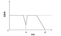
- FIG. 6 is a graph showing an example of the time change of this temperature difference.
- the temperature difference is temporarily reduced at time t1. In this case, it can be determined that the flow velocity of air in the region has temporarily decreased. Further, at time t2, the temperature difference is zero. In this case, it can be determined that the flow velocity of the air in the region is zero (that is, the fluid is stagnant).
- the compressor 11 As shown in FIG. 1 or FIG. 2 again, the compressor 11 according to the present embodiment is provided with a part of the air flowing through the region (intermediate stage) between the upstream region 11A and the downstream region 11B.
- An extractable air flow path L and an air release valve V provided on the air discharge flow path L are provided.
- the exhaust flow path L is connected to an exhaust flow path Le that communicates with the exhaust port of the turbine 3.
- the control device 90 adjusts the opening degree of the inlet guide blade 11C and the opening degree of the blow valve V based on the physical quantity detected by the detection device 21.
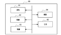
- the control device 90 includes a CPU 91 (Central Processing Unit), a ROM 92 (Read Only Memory), a RAM 93 (Random Access Memory), an HDD 94 (Hard Disk Drive), and a signal receiving module 95 (I / O: Input). / Output) is a computer.
- the signal receiving module 95 receives the physical quantity detected by the detection device 21 as an electric signal.
- the signal receiving module 95 may receive the amplified signal via, for example, a charge amplifier or the like.
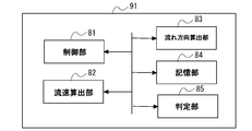
- the CPU 91 of the control device 90 has a control unit 81, a flow velocity calculation unit 82, a flow direction calculation unit 83, a storage unit 84, and a determination unit 85 by executing a program stored in the own device in advance. ..
- the control unit 81 controls other functional units provided in the control device 90.
- the above-mentioned temperature difference values detected by the detection device 21 are input as numerical information to the flow velocity calculation unit 82 and the flow direction calculation unit 83, respectively.
- the flow velocity calculation unit 82 calculates the flow velocity of air based on the absolute value of the temperature difference.
- the flow direction calculation unit 83 calculates the air flow direction based on the positive and negative of the temperature difference.
- the determination unit 85 compares the flow velocity calculated by the flow velocity calculation unit 82 and the flow direction calculated by the flow direction calculation unit 83 with the threshold value stored in the storage unit 84. For example, when a decrease in the flow velocity or a reversal of the flow direction is detected only in the second detection device 21B arranged in the downstream region 11B (that is, the temperature difference changes in the direction of becoming smaller), the inlet guide blade 11C An electric signal for adjusting the opening degree in the increasing direction is sent to the inlet guide blade 11C.
- the determination unit 85 determines. , An electric signal for adjusting the opening degree of the blow valve V in the increasing direction is sent to the blow valve V.
- the compressor 11 is driven by an electric motor or the like (not shown).
- an electric motor or the like By driving the compressor 11, external air is taken into the compressor 11 via the inlet guide blade 11C, and high-pressure air is generated.
- the combustor 2 mixes fuel with this high-pressure air and burns it to generate high-temperature and high-pressure combustion gas.
- the turbine 3 is rotationally driven by the combustion gas. The rotational force of the turbine 3 is taken out from the shaft end and used to drive a generator (not shown) or the like.
- the above-mentioned detection device 21 detects the flow velocity and the flow direction as physical quantities of air, and based on this, the control device 90 opens the opening degree of the inlet guide blade 11C and the release valve V. Adjust one of the degrees.
- the control device 90 adjusts in the direction of increasing the opening degree of the inlet guide blade 11C.
- the control device 90 adjusts the opening degree of the exhaust valve V in the increasing direction, and adjusts the amount of air extracted by the exhaust flow path L in the increasing direction.
- At least one detection device 21 is provided in the upstream side region 11A and the downstream side region 11B of the compressor 11.
- the detection device 21 detects the physical quantity of the working fluid.
- the control device 90 detects an abnormality occurring in the flow of the working fluid based on the change in the physical quantity.
- the control device 90 adjusts either the opening degree of the inlet guide blade 11C or the extraction amount. Thereby, the abnormality generated in the flow of the working fluid can be eliminated.
- the detection device 21 has a pair of temperature detection units 61 arranged in the flow direction Df, and a heating unit 62 provided between them.
- the working fluid passes through the pair of temperature detecting units 61 in the flow direction Df, the working fluid is heated by the heating unit 62. Therefore, there is a difference in the detected temperature between the temperature detection unit 61 located on the downstream side of the flow direction Df and the temperature detection unit 61 located on the upstream side. Therefore, it is possible to detect that the working fluid is flowing toward the side where the temperature detection unit 61 having a high detected temperature is located. That is, the flow direction Df of the working fluid can be detected.
- the change in the flow velocity of the working fluid can be detected by detecting the absolute value of the temperature difference detected by the pair of temperature detection units 61.
- a backflow that is, a change in the flow direction
- a decrease in the flow velocity which is a sign of the backflow occurs, these can be detected immediately. it can.
- the control device 90 adjusts in the direction of increasing the opening degree of the inlet guide blade 11C. As a result, the flow rate of the working fluid supplied to the downstream region 11B increases. As a result, surging can be avoided before it develops.
- the control device 90 adjusts the amount of extraction by the air flow path L in a direction of increasing. As a result, the working fluid stagnant in the upstream region 11A is extracted, and the stagnant flow is eliminated. As a result, surging can be avoided before it develops.
- the first embodiment of the present invention has been described above. It should be noted that various changes and modifications can be made to the above configuration as long as the gist of the present invention is not deviated.
- the configuration in which the detection device 21 is provided on the inner peripheral surface of the casing 30 in the upstream side region 11A and the downstream side region 11B has been described.
- the stationary blade stage 41 has a plurality of stationary blades 41p arranged in the circumferential direction along the inner peripheral surface of the casing 30. It is possible to provide the detection device 21 on at least one of these stationary blades 41p.
- the stationary blade 41p has an airfoil-shaped cross section extending from the upstream side to the downstream side in the flow direction Df. The surface of the flow direction Df facing the downstream side is recessed toward the downstream side to form a positive pressure surface S1. The surface facing the downstream side becomes a negative pressure surface S2 because it becomes convex toward the upstream side.
- the upstream edge is the front edge Ef
- the downstream edge is the trailing edge Ed. It is desirable that the detection device 21 is provided at a position on the negative pressure surface S2 that is biased to the outside or inward in the radial direction and is closer to the trailing edge Ed than the leading edge Ef.
- the negative pressure surface S2 of the stationary blade 41p is particularly liable to cause separation or backflow of the working fluid. According to the above configuration, since the detection device 21 is provided on the negative pressure surface S2, the above-mentioned peeling and backflow can be detected quickly and accurately.
- the second embodiment of the present invention will be described with reference to FIG.
- the same components as those in the first embodiment are designated by the same reference numerals, and detailed description thereof will be omitted.
- the above-mentioned detection device 21 is provided in the compressor 211 as a centrifugal compressor.
- the compressor 211 has a rotating shaft 50 that can rotate around the axis O, an impeller 5 that is integrally fixed to the rotating shaft 50, and a casing 55 that covers the impeller 5 from the outer peripheral side.
- the impeller 5 has a disk 51 extending in the radial direction of the axis O, a plurality of blades 52 provided on a surface facing the upstream side of the disk 51, and a cover 53 covering these blades 52 from the upstream side. ..
- An impeller flow path P2 through which air as a working fluid flows is formed between the cover 53, the disk 51, and the blades 52 adjacent to each other.
- a guide flow path P1 communicating with the impeller flow path P2, a diffuser flow path P3, a return bend portion P4, and a return flow path P5 are formed inside the casing 55.
- the diffuser flow path P3 communicates with the radial outer end of the impeller flow path P2 and extends outward in the radial direction.
- the return bend portion P4 communicates with the radially outer end of the diffuser flow path P3 and extends in the direction of reversing inward in the radial direction.
- the breeze flow path L'described in the first embodiment described above is connected to the outermost radial direction of the return bend portion P4.
- the return flow path P5 communicates with the downstream side of the return bend portion P4 and also communicates with the guide flow path P1 of the subsequent stage located on the downstream side.
- a return vane 54 is provided in the return flow path P5.
- the region on the upstream side of the impeller 5 is the upstream region 211A
- the region on the downstream side of the impeller 5 is the downstream region 211B.
- the detection device 21 (first detection device 21A) described in the first embodiment is provided in the upstream region 211A.
- the first detection device 21A is provided on the inner peripheral surface of the casing 55 in the guide flow path P1.
- a second detection device 21B is provided in the downstream region 211B.
- one second detection device 21B is provided on each of the upstream side wall surface and the downstream side wall surface of the diffuser flow path P3.
- one second detection device 21B is provided at each of the upstream end and the downstream end of the return vane 54. It is also possible to adopt a configuration in which the second detection device 21B is provided in only one of the diffuser flow path P3 and the return vane 54.
- the detection device 21 is provided in at least one of the diffuser flow path P3 and the return flow path P5, the occurrence of surging in the downstream region 211B and its sign can be detected finely and accurately. can do.
- the detection device 21 has only the above-mentioned second detection device 21B. Further, the compressor system 200 does not have the above-mentioned air discharge flow path L (extraction unit) and the air discharge valve V. Further, the configuration of the control device 90 is different from each of the above embodiments.
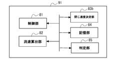
- the control device 90 includes a control unit 81, a flow velocity calculation unit 82, a closing speed determination unit 83b, a storage unit 84, and a determination unit 85.
- the control unit 81 controls other functional units provided in the control device 90.
- the above-mentioned temperature difference value detected by the detection device 21 is input to the flow velocity calculation unit 82 as numerical information.
- the flow velocity calculation unit 82 calculates the flow velocity (or flow rate) of air based on the absolute value of the temperature difference.
- the determination unit 85 compares the flow velocity calculated by the flow velocity calculation unit 82 with the threshold value stored in the storage unit 84.
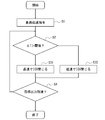
- the closing speed determination unit 83b determines the closing speed of the inlet guide blade 11C based on the determination result of the determination unit 85. More specifically, as shown in FIG. 11, after the load reduction command (step S1) is issued, the magnitude of the above temperature difference (that is, the flow velocity) and the predetermined threshold value is compared. (Step S2). When it is determined that the temperature difference is larger than the threshold value, the inlet guide blade 11C is closed at a relatively high speed (step S31).
- step S4 it is determined whether or not the output of the gas turbine 100 has decreased to the target output.
- the steps S2 to S4 described above are repeated again.
- the process is completed.
- the speed at which the control device 90 closes the inlet guide blade 11C is determined based on the temperature difference detected by the pair of temperature detection units 61, that is, the speed or flow rate of the fluid. Therefore, the inlet guide blade 11C can be closed at an appropriate speed while avoiding the above-mentioned surge and unstable combustion. As a result, the load on the gas turbine 100 can be reduced stably and quickly.
- the optimum speed for closing the inlet guide blade 11C can be determined only by evaluating the flow velocity or the flow rate 9 based on a predetermined threshold value. As a result, the load on the gas turbine 100 can be quickly reduced while suppressing the possibility of surges and unstable combustion occurring.
- control device 90 that is, the closing speed
- the configuration described in the first embodiment that is, the configuration including the first detection device 21A, the blow path L, and the blow valve V. It is also possible to apply in combination with a control device 90) further including a determination unit 83b.
- the operation of the closing speed determining unit 83b in the third embodiment is an example, and as another example, the closing speed determining unit 83b can be configured to perform the processes shown in FIGS. 12 and 13.
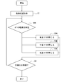
- the control device 90 determines which of the plurality of predetermined continuous numerical ranges the temperature difference (that is, the flow velocity or the flow rate) detected by the temperature detection device 21 belongs to (that is,). Step 2B). Further, the inlet guide blade 11C is closed by selecting a predetermined closing speed corresponding to the numerical range to which the inlet belongs (steps S3A to S3C). In the example of the figure, three speeds (high speed, medium speed, and low speed) are set as the speeds for closing the inlet guide blade 11C, but the number of speed ranges is not limited to three, and four or more speeds are set. It is also possible to set the range.
- the inlet guide blade 11C can be closed by selecting a speed determined according to the numerical range to which the detection result of the temperature detection device 21 belongs. That is, the speed at which the inlet guide blade 11C is closed can be finely determined based on the magnitude of the temperature difference (that is, the flow velocity or the flow rate). As a result, the load on the gas turbine 100 can be reduced more quickly while further reducing the possibility of surges and unstable combustion occurring.
- control device 90 refers to a table showing the relationship between the detection result of the temperature detection unit 21 and the optimum speed for closing the inlet guide blade 11C according to the value of the temperature difference.
- the speed at which the blade 11C is closed is determined (step S2C). After that, the inlet guide blade 11C is closed at the determined speed (step S3C).
- the inlet guide blade 11C can be closed by selecting the speed according to the table showing the relationship between the optimum speed and the temperature difference (that is, the flow velocity or the flow rate). That is, the speed at which the inlet guide blade 11C is closed can be determined more finely based on the magnitude of the temperature difference. As a result, the load on the gas turbine 100 can be reduced more quickly while further reducing the possibility of surges and unstable combustion occurring.
Landscapes
- Engineering & Computer Science (AREA)
- Mechanical Engineering (AREA)
- General Engineering & Computer Science (AREA)
- Physics & Mathematics (AREA)
- Geometry (AREA)
- Life Sciences & Earth Sciences (AREA)
- Sustainable Development (AREA)
- Control Of Positive-Displacement Air Blowers (AREA)
- Structures Of Non-Positive Displacement Pumps (AREA)
Abstract
圧縮機システム(1)は、作動流体が流入する上流側領域(11A)と、作動流体の圧力が上流側領域(11A)よりも高い下流側領域(11B)と、上流側領域(11A)のさらに上流側に設けられ、流入する作動流体の流量を変化させることが可能な入口案内翼(11C)と、上流側領域(11A)と下流側領域(11B)との間の部分に設けられ、作動流体の少なくとも一部を抽出可能な抽出部(L)と、を有する圧縮機(11)と、上流側領域(11A)、及び下流側領域(11B)に少なくとも1つずつ設けられ、作動流体の物理量を検出する検出装置(21)と、物理量の変化に基づいて、入口案内翼(11C)の開度、及び抽出部(L)による抽出量を調節する制御装置(90)と、を備える。
Description
本発明は、圧縮機システムに関する。
本願は、2019年3月26日に、日本に出願された特願2019-059225号に基づき優先権を主張し、その内容をここに援用する。
本願は、2019年3月26日に、日本に出願された特願2019-059225号に基づき優先権を主張し、その内容をここに援用する。
例えば軸流圧縮機や遠心圧縮機を含むターボ圧縮機では、回転数を一定に保ったままで圧力比を高めるように運転点を変更すると、旋回失速やサージングと呼ばれる現象が発生することが知られている。特にサージングは、圧縮機内部における作動流体の逆流や、回転軸の振動につながる可能性がある。このため、サージングを回避、又は抑制することが可能な技術に対する要請が高まっている。
このような技術の一例として、下記特許文献1に記載されたものが知られている。特許文献1には、静圧センサや動圧センサ、流速センサを含む各種の検出装置と、これら検出装置による検出値を周波数処理することによって、サージングの予兆となる変化を捉える技術が開示されている。
しかしながら、上記特許文献1に記載された装置では、サージングがある程度進行した状態にならないと、検出装置による検出値がノイズ(変動成分)に埋もれてしまう場合がある。これにより、サージングの予兆を精度高く検出することができない可能性がある。
本発明は上記課題を解決するためになされたものであって、サージングの発生をより高い精度で検知できるとともに、サージングを抑制することが可能な圧縮機システムを提供することを目的とする。
本発明の一態様に係る圧縮機システムは、作動流体が流入する上流側領域と、該上流側領域に連通するとともに、前記作動流体の圧力が前記上流側領域よりも高い下流側領域と、前記上流側領域のさらに上流側に設けられ、該上流側領域に流入する前記作動流体の流量を変化させることが可能な入口案内翼と、前記上流側領域と前記下流側領域との間の部分に設けられ、前記作動流体の少なくとも一部を抽出可能な抽出部と、を有する圧縮機と、前記上流側領域、及び前記下流側領域に少なくとも1つずつ設けられ、前記作動流体の物理量を検出する検出装置と、前記検出装置が検出した前記物理量の変化に基づいて、前記入口案内翼の開度、及び前記抽出部による抽出量のいずれか一方を調節する制御装置と、を備える。
上記構成によれば、圧縮機の上流側領域と下流側領域とに、少なくとも1つずつの検出装置が設けられている。検出装置は、作動流体の物理量を検出する。制御装置は、この物理量の変化に基づいて、作動流体の流れに生じた異常を検知する。制御装置は、入口案内翼の開度、及び抽出量のいずれか一方を調節する。これにより、作動流体の流れに生じた異常を解消することができる。
上記圧縮機システムでは、前記検出装置は、前記作動流体の流れ方向に配列された一対の温度検出部と、該一対の温度検出部の間に配置され、前記作動流体を加熱する加熱部と、を有し、前記物理量は、前記一対の温度検出部によって検出された前記作動流体の温度差に基づく該作動流体の流れ方向、及び流速であってもよい。
上記構成によれば、検出装置は、流れ方向に配列された一対の温度検出部と、その間に設けられた加熱部と、を有している。一対の温度検出部を流れ方向に作動流体が通過する際、加熱部によって作動流体が加熱される。したがって、流れ方向の下流側に位置する温度検出部と、上流側に位置する温度検出部との間で、検出される温度に差が生じる。したがって、検出された温度が高い温度検出部が位置する側に作動流体が流れていることを検知することができる。つまり、作動流体の流れ方向を検知することができる。さらに、一対の温度検出部で検出された温度差の絶対値を検出することによって、作動流体の流速の変化を検知することもできる。これにより、例えば圧縮機の内部で作動流体の流れに逆流(即ち、流れ方向の変化)が生じたり、逆流の予兆となる流速の低下が生じたりした場合に、これらを直ちに検知することができる。
上記圧縮機システムでは、前記温度検出部、及び前記加熱部は、前記作動流体に直接的に曝されていてもよい。
上記構成によれば、作動流体の物理量の変化を直ちに検出することができる。これにより、装置全体の応答性を高めることができる。
上記圧縮機システムでは、前記制御装置は、前記下流側領域で前記温度差が小さくなる方向に変化した場合には、前記入口案内翼の開度を大きくなる方向に調節してもよい。
上記構成によれば、下流側領域の検出装置で検出された一対の温度検出部による温度差が小さくなった場合、当該下流側領域で作動流体の流速が低下したと判断することができる。流速の低下が続くと、最終的には流れ方向の変化につながる可能性がある。つまり、流速の低下は、逆流の予兆であると言える。この場合、圧縮機の下流側領域における作動流体の流量が過大となり、作動流体の流れが停滞し始めている(サージングが発生しつつある)と判断することができる。そこで、制御装置は、入口案内翼の開度を大きくなる方向に調節する。これにより、下流側領域に供給される作動流体の流量が減少する。その結果、発達する前にサージングを回避することができる。
上記圧縮機システムでは、前記制御装置は、前記上流側領域で前記温度差が小さくなる方向に変化した場合には、前記抽出量を大きくなる方向に調節してもよい。
上記構成によれば、上流側領域の検出装置で検出された一対の温度検出部による温度差が小さくなった場合、当該上流側領域で作動流体の流速が低下したと判断することができる。流速の低下が続くと、最終的には流れ方向の変化につながる可能性がある。つまり、流速の低下は、逆流の予兆であると言える。この場合、圧縮機の上流側領域における作動流体の流量が過大となり、作動流体の流れが停滞し始めている(サージングが発生しつつある)と判断することができる。そこで、制御装置は、抽出量を大きくなる方向に調節する。これにより、上流側領域で停滞していた作動流体が抽出され、流れの停滞が解消される。その結果、発達する前にサージングを回避することができる。
上記圧縮機システムでは、前記圧縮機は、軸線回りに回転可能な回転軸と、該回転軸に設けられ、前記軸線方向に配列された複数の動翼段と、前記回転軸及び前記動翼段を外周側から覆うケーシングと、該ケーシングの内周面に設けられ、前記複数の動翼段と前記軸線方向に交互に配列された複数の静翼段と、を有し、前記上流側領域は、前記複数の動翼段のうち、最も上流側から数えて3段目の前記動翼段よりも上流側の領域であり、前記下流側領域は、前記複数の動翼段のうち、最も下流側から数えて3段目の前記動翼段よりも下流側の領域であってもよい。
ここで、上記のような圧縮機では、最も上流側から数えて3段目の動翼段よりも上流側の領域、及び最も下流側から数えて3段目の動翼段よりも下流側の領域で、特にサージングが発生しやすいことが知られている。上記構成によれば、これらの領域をそれぞれ上流側領域、下流側領域としていることから、サージングの発生やその予兆を早期かつ正確に検知することができる。
上記圧縮機システムでは、前記静翼段は、前記軸線に対する径方向に延びるとともに、周方向に配列され、上流側を向く負圧面、及び下流側を向く正圧面を有する複数の静翼を有し、前記検出装置は、前記負圧面に設けられていてもよい。
ここで、静翼の負圧面では特に作動流体の剥離や逆流を生じやすい。上記の構成によれば、この負圧面に検出装置が設けられていることから、上記の剥離や逆流を早期かつ正確に検知することができる。
上記圧縮機システムでは、前記圧縮機は、軸線回りに回転可能な回転軸と、該回転軸に設けられたインペラと、該インペラを外周側から覆うとともに、前記インペラの上流側、及び下流側に前記作動流体が流通する流路を形成するケーシングと、を有し、前記上流側領域は、前記流路における前記インペラよりも上流側の領域であり、前記下流側領域は、前記流路における前記インペラよりも下流側の領域であってもよい。
ここで、上記のような圧縮機では、インペラよりも上流側の領域、及びインペラよりも下流側の領域で、特にサージングが発生しやすいことが知られている。上記構成によれば、これらの領域をそれぞれ上流側領域、下流側領域としていることから、サージングの発生やその予兆を早期かつ正確に検知することができる。
上記圧縮機システムでは、前記流路は、前記インペラの下流側に設けられ、前記軸線に対する径方向内側から外側に向かって前記作動流体を導くディフューザ流路、及び該ディフューザ流路のさらに下流側に設けられ、径方向外側から内側に向かって前記作動流体を導くリターン流路を有し、前記検出装置は、前記ディフューザ流路、及び前記リターン流路の少なくとも一方に設けられていてもよい。
上記構成によれば、ディフューザ流路、及びリターン流路の少なくとも一方に検出装置が設けられていることから、下流側領域におけるサージングの発生やその予兆をきめ細かく、正確に検知することができる。
本発明の一態様に係る圧縮機システムは、作動流体が流入する上流側領域と、該上流側領域に連通するとともに、前記作動流体の圧力が前記上流側領域よりも高い下流側領域と、前記上流側領域のさらに上流側に設けられ、該上流側領域に流入する前記作動流体の流量を変化させることが可能な入口案内翼と、前記上流側領域と前記下流側領域との間の部分に設けられ、前記作動流体の少なくとも一部を抽出可能な抽出部と、を有する圧縮機と、前記上流側領域、及び前記下流側領域に少なくとも1つずつ設けられ、前記作動流体の物理量を検出する検出装置と、前記検出装置が検出した前記物理量の変化に基づいて、前記入口案内翼の開度、及び前記抽出部による抽出量を調節する制御装置と、を備え、前記圧縮機は、軸線回りに回転可能な回転軸と、該回転軸に設けられ、前記軸線方向に配列された複数の動翼段と、前記回転軸及び前記動翼段を外周側から覆うケーシングと、該ケーシングの内周面に設けられ、前記複数の動翼段と前記軸線方向に交互に配列された複数の静翼段と、を有し、前記上流側領域は、前記複数の動翼段のうち、最も上流側から数えて3段目の前記動翼段よりも上流側の領域であり、前記下流側領域は、前記複数の動翼段のうち、最も下流側から数えて3段目の前記動翼段よりも下流側の領域であり、前記静翼段は、前記軸線に対する径方向に延びるとともに、周方向に配列され、上流側を向く負圧面、及び下流側を向く正圧面を有する複数の静翼を有し、前記検出装置は、前記負圧面に設けられている。
圧縮機の上流側領域と下流側領域とに、少なくとも1つずつの検出装置が設けられている。検出装置は、作動流体の物理量を検出する。制御装置は、この物理量の変化に基づいて、作動流体の流れに生じた異常を検知する。制御装置は、入口案内翼の開度、及び抽出量のいずれか一方を調節する。これにより、作動流体の流れに生じた異常を解消することができる。さらに、上記のような圧縮機では、最も上流側から数えて3段目の動翼段よりも上流側の領域、及び最も下流側から数えて3段目の動翼段よりも下流側の領域で、特にサージングが発生しやすいことが知られている。上記構成によれば、これらの領域をそれぞれ上流側領域、下流側領域としていることから、サージングの発生やその予兆を早期かつ正確に検知することができる。ここで、静翼の負圧面では特に作動流体の剥離や逆流を生じやすい。上記の構成によれば、この負圧面に検出装置が設けられていることから、上記の剥離や逆流を早期かつ正確に検知することができる。
上記圧縮機システムでは、前記検出装置は、前記作動流体の流れ方向に配列された一対の温度検出部と、該一対の温度検出部の間に配置され、前記作動流体を加熱する加熱部と、を有し、前記物理量は、前記一対の温度検出部によって検出された前記作動流体の温度差であり、前記圧縮機の負荷を低減する指令が出された場合に、前記制御装置は、前記物理量の大きさに基づいて、前記入口案内翼を閉じる速度を決定してもよい。
ここで、圧縮機の負荷を低減する指令が出された場合に、作動流体の流入量を下げるべく入口案内翼を過度に高速で閉じると、下流側領域で圧縮される作動流体の量が不足して上流側に逆流する(サージが発生する)虞がある。一方で、入口案内翼を過度に低速で閉じると、下流側に設けられた燃焼器への作動流体の供給量が過剰となることで燃焼ガスの温度が低下する。その結果、燃焼振動の発生やNOx排出量の増加につながる虞がある。上記構成によれば、一対の温度検出部が検出した温度差、つまり流体の速度又は流量に基づいて、制御装置が入口案内翼を閉じる速度を決定する。このため、上記のサージや不安定燃焼を回避しつつ、入口案内翼を適切な速度で閉めることができる。その結果、安定的かつ迅速に圧縮機の負荷を低減することができる。
上記圧縮機システムでは、前記制御装置は、前記物理量が予め定められた閾値よりも大きい場合に、前記入口案内翼を相対的に高い速度で閉じ、前記物理量が前記閾値よりも小さい場合に、前記入口案内翼を相対的に低い速度で閉じてもよい。
上記構成によれば、予め定められた閾値に基づいて物理量の大きさを評価することのみによって、入口案内翼を閉じる最適な速度を決定することができる。これにより、サージや不安定燃焼の発生する可能性を低く抑えつつ、迅速に圧縮機の負荷を低減することができる。
上記圧縮機システムでは、前記制御装置は、前記物理量が、予め定められた複数の数値範囲のうちのいずれに属するかを判定し、該属する数値範囲に対応して予め定められた速度を選択して前記入口案内翼を閉じてもよい。
上記構成によれば、物理量が属する数値範囲に対応して定められた速度を選択して入口案内翼を閉じることができる。つまり、物理量の大きさに基づいて、きめ細かく入口案内翼を閉じる速度を決定することができる。その結果、サージや不安定燃焼の発生する可能性をさらに低く抑えつつ、より迅速に圧縮機の負荷を低減することができる。
上記圧縮機システムでは、前記制御装置は、前記物理量、及び該物理量の値に応じた前記入口案内翼を閉じる最適な速度との関係を示すテーブルを参照して、前記入口案内翼を閉じる速度を決定してもよい。
上記構成によれば、入口案内翼を閉じる最適な速度と物理量との関係を示すテーブルに従って速度を選択して入口案内翼を閉じることができる。つまり、物理量の大きさに基づいて、さらにきめ細かく入口案内翼を閉じる速度を決定することができる。これにより、サージや不安定燃焼の発生する可能性をより一層低く抑えつつ、さらに迅速に圧縮機の負荷を低減することができる。
本発明の一態様に係る圧縮機システムは、作動流体が流入する上流側領域と、該上流側領域に連通するとともに、前記作動流体の圧力が前記上流側領域よりも高い下流側領域と、前記上流側領域のさらに上流側に設けられ、該上流側領域に流入する前記作動流体の流量を変化させることが可能な入口案内翼と、を有する圧縮機と、前記下流側領域に少なくとも1つ設けられ、前記作動流体の物理量を検出する検出装置と、前記検出装置が検出した前記物理量の変化に基づいて、前記入口案内翼の開度を調節する制御装置と、を備え、前記検出装置は、前記作動流体の流れ方向に配列された一対の温度検出部と、該一対の温度検出部の間に配置され、前記作動流体を加熱する加熱部と、を有し、前記物理量は、前記一対の温度検出部によって検出された前記作動流体の温度差であり、前記圧縮機の負荷を低減する指令が出された場合に、前記制御装置は、前記物理量の大きさに基づいて、前記入口案内翼を閉じる速度を決定する。
ここで、圧縮機の負荷を低減する指令が出された場合に、作動流体の流入量を下げるべく入口案内翼を過度に高速で閉じると、下流側領域で圧縮される作動流体の量が不足して上流側に逆流する(サージが発生する)虞がある。一方で、入口案内翼を過度に低速で閉じると、下流側に設けられた燃焼器への作動流体の供給量が過剰となることで燃焼ガスの温度が低下する。その結果、燃焼振動の発生やNOx排出量の増加につながる虞がある。上記構成によれば、一対の温度検出部が検出した温度差、つまり流体の速度又は流量に基づいて、制御装置が入口案内翼を閉じる速度を決定する。このため、上記のサージや不安定燃焼を回避しつつ、入口案内翼を適切な速度で閉めることができる。その結果、安定的かつ迅速に圧縮機の負荷を低減することができる。
上記圧縮機システムでは、前記制御装置は、前記物理量が予め定められた閾値よりも大きい場合に、前記入口案内翼を相対的に高い速度で閉じ、前記物理量が前記閾値よりも小さい場合に、前記入口案内翼を相対的に低い速度で閉じてもよい。
上記構成によれば、予め定められた閾値に基づいて物理量の大きさを評価することのみによって、入口案内翼を閉じる最適な速度を決定することができる。これにより、サージや不安定燃焼の発生する可能性を低く抑えつつ、迅速に圧縮機の負荷を低減することができる。
上記圧縮機システムでは、前記制御装置は、前記物理量が、予め定められた複数の数値範囲のうちのいずれに属するかを判定し、該属する数値範囲に対応して予め定められた速度を選択して前記入口案内翼を閉じてもよい。
上記構成によれば、物理量が属する数値範囲に対応して定められた速度を選択して入口案内翼を閉じることができる。つまり、物理量の大きさに基づいて、きめ細かく入口案内翼を閉じる速度を決定することができる。その結果、サージや不安定燃焼の発生する可能性をさらに低く抑えつつ、より迅速に圧縮機の負荷を低減することができる。
上記圧縮機システムでは、前記制御装置は、前記物理量、及び該物理量の値に応じた前記入口案内翼を閉じる最適な速度との関係を示すテーブルを参照して、前記入口案内翼を閉じる速度を決定してもよい。
上記構成によれば、入口案内翼を閉じる最適な速度と物理量との関係を示すテーブルに従って速度を選択して入口案内翼を閉じることができる。つまり、物理量の大きさに基づいて、さらにきめ細かく入口案内翼を閉じる速度を決定することができる。これにより、サージや不安定燃焼の発生する可能性をより一層低く抑えつつ、さらに迅速に圧縮機の負荷を低減することができる。
本発明によれば、サージングの発生をより高い精度で検知できるとともに、サージングを抑制することが可能な圧縮機システムを提供することができる。
[第一実施形態]
本発明の第一実施形態について、図1から図6を参照して説明する。図1に示すように、本実施形態に係るガスタービン100は、圧縮機システム1と、燃焼器2と、タービン3と、を備えている。圧縮機システム1は、外部の空気(作動流体)を圧縮して高圧空気を生成する。燃焼器2は、高圧空気に燃料を混合して燃焼させ、高温高圧の燃焼ガスを生成する。タービン3は、この燃焼ガスによって回転駆動される。タービン3と圧縮機システム1は、軸線Oに沿って延びる回転軸4によって接続されている。したがって、タービン3の回転は回転軸4を介して圧縮機システム1に伝達される。
本発明の第一実施形態について、図1から図6を参照して説明する。図1に示すように、本実施形態に係るガスタービン100は、圧縮機システム1と、燃焼器2と、タービン3と、を備えている。圧縮機システム1は、外部の空気(作動流体)を圧縮して高圧空気を生成する。燃焼器2は、高圧空気に燃料を混合して燃焼させ、高温高圧の燃焼ガスを生成する。タービン3は、この燃焼ガスによって回転駆動される。タービン3と圧縮機システム1は、軸線Oに沿って延びる回転軸4によって接続されている。したがって、タービン3の回転は回転軸4を介して圧縮機システム1に伝達される。
圧縮機システム1は、圧縮機11と、入口案内翼11Cと、検出装置21と、放風流路L(抽出部)と、放風弁Vと、制御装置90と、を有している。圧縮機11は、軸線O方向一方側(上流側)から導かれた空気を圧縮して他方側(下流側)に設けられた燃焼器2に供給する。つまり、この圧縮機11は、軸流圧縮機である。詳しくは後述するが、圧縮機11は、軸線O方向における上流側に位置する上流側領域11Aと、下流側に位置する下流側領域11Bと、を有している。下流側領域11Bでは、上流側領域11Aに比べて作動流体(空気)の圧力が高くなっている。上流側領域11Aには、入口案内翼11Cを介して外部の空気が導入される。入口案内翼11Cは、上流側領域11Aに流入する空気の量を調節するために設けられている。入口案内翼11Cは、後述する制御装置90から送出された電気信号によってその開度を変化させることが可能である。
上流側領域11A内には、当該上流側領域11Aを流通する空気の物理量を検出する検出装置21(第一検出装置21A)が少なくとも1つ設けられている。同様に、下流側領域11B内には、当該下流側領域11Bを流通する空気の物理量を検出する検出装置21(第二検出装置21B)が少なくとも1つ設けられている。
ここで、図2に示すように、圧縮機11は、軸線O回りに回転可能な回転軸4と、この回転軸4の外周面上で、軸線O方向に配列された複数の動翼段42と、これら回転軸4及び動翼段42を外周側から覆うケーシング30と、ケーシング30の内周面に設けられた複数の静翼段41と、を有している。静翼段41は、軸線O方向において動翼段42と交互に配列されている。上述の上流側領域11Aとは、複数の動翼段42のうち、最も上流側から数えて3段目の動翼段42よりも上流側の領域を指す。即ち、第一検出装置21Aは、最も上流側の動翼段42(第一動翼段42A)、及び上流側から数えて2段目の動翼段42(第二動翼段42B)に対応するケーシング30の内周面に設けられている。なお、第一動翼段42Aと隣接する第一静翼段41A、及び第二動翼段42Bに隣接する第二静翼段41Bに第一検出装置21Aを設けることも可能である。
さらに、上述の下流側領域11Bとは、複数の動翼段42のうち、最も下流側から数えて3段目の動翼段42よりも下流側の領域を指す。即ち、第二検出装置21Bは、最も下流側の動翼段42(出口最終動翼段42D)、及び下流側から数えて2段目の動翼段42(出口動翼段42C)に対応するケーシング30の内周面に設けられている。なお、出口最終動翼段42Dに隣接する出口最終静翼段41D、及び出口動翼段42Cに隣接する出口静翼段41Cに第二検出装置21Bを設けることも可能である。さらに、出口最終動翼段42Dの下流側に設けられているディフューザ流路静翼段41Eに対応するケーシング30の内周面に第二検出装置21Bを設けることも可能である。
検出装置21は、圧縮機11内における空気の流れ方向Df、及び流速の変化を物理量として検出する。図3に示すように、検出装置21は、流れ方向Dfに間隔をあけて配列された一対の温度検出部61と、これら温度検出部61同士の間に設けられた加熱部62とを有している。温度検出部61、及び加熱部62は、いずれも作動流体に直接的に曝されている。即ち、これら温度検出部61、及び加熱部62は、ケーシング30の表面(内周面)に露出している。温度検出部61は、自身に接触した空気の温度を検出する。加熱部62は、自身の近傍を流れる空気を加熱する。加熱部62によって空気が加熱されることから、流れ方向Df下流側に位置する温度検出部61が検出する空気の温度Tdは、上流側に位置する温度検出部61が検出する空気の温度Tuよりも高くなる。さらに、これらの値の温度差(Td-Tu)の値は、空気の流速が高まるにつれて大きくなる。また、空気の流れ方向Dfが変化した場合(即ち、流れ方向が逆転した場合)には、温度差(Td-Tu)は負の値となる。なお、図6は、この温度差の時間変化の一例を示すグラフである。同図の例では、時刻t1において温度差が一時的に小さくなっている。この場合、当該領域における空気の流速が一時的に低下したと判断できる。また、時刻t2においては、温度差がゼロとなっている。この場合、当該領域における空気の流速がゼロとなった(即ち、流体の滞留が生じている)と判断することができる。
再び図1又は図2に示すように、本実施形態に係る圧縮機11には、上記の上流側領域11Aと下流側領域11Bとの間の領域(中間段)を流通する空気の一部を抽出可能な放風流路Lと、この放風流路L上に設けられた放風弁Vと、が設けられている。放風流路Lは、タービン3の排気口に連通する排気流路Leに接続されている。放風弁Vの開度を調節することによって、放風流路Lによって抽出される空気の量(抽出量)を変化させることができる。
制御装置90は、上記の検出装置21によって検出された物理量に基づいて、入口案内翼11Cの開度、及び放風弁Vの開度を調節する。図4に示すように、制御装置90は、CPU91(Central Processing Unit)、ROM92(Read Only Memory)、RAM93(Random Access Memory)、HDD94(Hard Disk Drive)、信号受信モジュール95(I/O:Input/Output)を備えるコンピュータである。信号受信モジュール95は、検出装置21で検出された物理量を電気信号として受信する。信号受信モジュール95は、例えばチャージアンプ等を介して増幅された信号を受信してもよい。
図5に示すように、制御装置90のCPU91は予め自装置で記憶するプログラムを実行することにより、制御部81、流速算出部82、流れ方向算出部83、記憶部84、判定部85を有する。制御部81は制御装置90に備わる他の機能部を制御する。流速算出部82、及び流れ方向算出部83には、検出装置21によって検出された上述の温度差の値がそれぞれ数値情報として入力される。
流速算出部82は、温度差の絶対値に基づいて、空気の流速を算出する。流れ方向算出部83は、温度差の正負に基づいて、空気の流れ方向を算出する。判定部85は、流速算出部82によって算出された流速、及び流れ方向算出部83によって算出された流れ方向を、記憶部84に記憶された閾値と比較する。例えば、下流側領域11Bに配置された第二検出装置21Bのみで流速の減少、又は流れ方向の逆転が検出された(即ち、温度差が小さくなる方向に変化した)場合、入口案内翼11Cの開度を大きくなる方向に調節する電気信号を当該入口案内翼11Cに送出する。一方で、上流側領域11Aに配置された第一検出装置21Aのみで流速の減少、又は流れ方向の逆転が検出された(即ち、温度差が小さくなる方向に変化した)場合、判定部85は、放風弁Vの開度を大きくなる方向に調節する電気信号を放風弁Vに送出する。
次いで、本実施形態に係るガスタービン100の動作について説明する。ガスタービン100を運転するに当たっては、まず圧縮機11を不図示の電動機等で駆動する。圧縮機11が駆動されることにより、外部の空気が入口案内翼11Cを介して圧縮機11に取り込まれ、高圧空気が生成される。燃焼器2は、この高圧空気に燃料を混合して燃焼させ、高温高圧の燃焼ガスを生成する。タービン3は燃焼ガスによって回転駆動される。タービン3の回転力は軸端から取り出されて発電機(不図示)等の駆動に用いられる。
ここで、上記のような圧縮機11では、回転数を一定に保ったままで圧力比を高めるように運転点を変更すると、旋回失速やサージングと呼ばれる現象が発生することが知られている。特にサージングは、圧縮機内部における作動流体の逆流や、回転軸の振動につながる可能性がある。そこで、本実施形態では、上述の検出装置21によって空気の物理量としての流速、及び流れ方向を検出し、これに基づいて制御装置90が入口案内翼11Cの開度、及び放風弁Vの開度のいずれか一方を調節する。
具体的には、下流側領域11Bの第二検出装置21Bで検出された一対の温度検出部61による温度差が小さくなった場合、当該下流側領域11Bで作動流体の流速が低下したと判断することができる。流速の低下が続くと、最終的には流れ方向の変化につながる可能性がある。つまり、流速の低下は、逆流の予兆であると言える。この場合、圧縮機11の下流側領域11Bにおける作動流体の流量が過大となり、作動流体の流れが停滞し始めている(サージングが発生しつつある)と判断することができる。そこで、制御装置90は、入口案内翼11Cの開度を大きくする方向に調節する。
一方で、上流側領域11Aの第一検出装置21Aで検出された一対の温度検出部61による温度差が小さくなった場合、当該上流側領域11Aで作動流体の流速が低下したと判断することができる。この場合、圧縮機11の上流側領域11Aにおける作動流体の流量が過大となり、作動流体の流れが停滞し始めている(サージングが発生しつつある)と判断することができる。そこで、制御装置90は、放風弁Vの開度を大きくなる方向に調節し、放風流路Lによる空気の抽出量を大きくなる方向に調節する。これにより、例えば圧縮機の内部で作動流体の流れに逆流(即ち、流れ方向の変化)が生じたり、逆流の予兆となる流速の低下が生じたりした場合に、これらを直ちに検知することができる。
以上、説明したように、本実施形態に係る構成によれば、圧縮機11の上流側領域11Aと下流側領域11Bとに、少なくとも1つずつの検出装置21が設けられている。検出装置21は、作動流体の物理量を検出する。制御装置90は、この物理量の変化に基づいて、作動流体の流れに生じた異常を検知する。制御装置90は、入口案内翼11Cの開度、及び抽出量のいずれか一方を調節する。これにより、作動流体の流れに生じた異常を解消することができる。
さらに、上記構成によれば、検出装置21は、流れ方向Dfに配列された一対の温度検出部61と、その間に設けられた加熱部62と、を有している。一対の温度検出部61を流れ方向Dfに作動流体が通過する際、加熱部62によって作動流体が加熱される。したがって、流れ方向Dfの下流側に位置する温度検出部61と、上流側に位置する温度検出部61との間で、検出される温度に差が生じる。したがって、検出された温度が高い温度検出部61が位置する側に向かって作動流体が流れていることを検知することができる。つまり、作動流体の流れ方向Dfを検知することができる。さらに、一対の温度検出部61で検出された温度差の絶対値を検出することによって、作動流体の流速の変化を検知することもできる。これにより、例えば圧縮機11の内部で作動流体の流れに逆流(即ち、流れ方向の変化)が生じたり、逆流の予兆となる流速の低下が生じたりした場合に、これらを直ちに検知することができる。
加えて、上記構成によれば、下流側領域11Bの検出装置21で検出された一対の温度検出部61による温度差が小さくなった場合、当該下流側領域11Bで作動流体の流速が低下したと判断することができる。流速の低下が続くと、最終的には流れ方向の変化につながる可能性がある。つまり、流速の低下は、逆流の予兆であると言える。この場合、圧縮機11の下流側領域11Bにおける作動流体の流量が過大となり、作動流体の流れが停滞し始めている(サージングが発生しつつある)と判断することができる。そこで、制御装置90は、入口案内翼11Cの開度を大きくする方向に調節する。これにより、下流側領域11Bに供給される作動流体の流量が増加する。その結果、発達する前にサージングを回避することができる。
また、上記構成によれば、上流側領域11Aの検出装置21で検出された一対の温度検出部61による温度差が小さくなった場合、当該上流側領域11Aで作動流体の流速が低下したと判断することができる。流速の低下が続くと、最終的には流れ方向の変化につながる可能性がある。つまり、流速の低下は、逆流の予兆であると言える。この場合、圧縮機11の上流側領域11Aにおける作動流体の流量が過大となり、作動流体の流れが停滞し始めている(サージングが発生しつつある)と判断することができる。そこで、制御装置90は、放風流路Lによる抽出量を大きくなる方向に調節する。これにより、上流側領域11Aで停滞していた作動流体が抽出され、流れの停滞が解消される。その結果、発達する前にサージングを回避することができる。
ここで、上記のような圧縮機11では、最も上流側から数えて3段目の動翼段42よりも上流側の領域、及び最も下流側から数えて3段目の動翼段42よりも下流側の領域で、特にサージングが発生しやすいことが知られている。上記構成によれば、これらの領域をそれぞれ上流側領域11A、下流側領域11Bとしていることから、サージングの発生やその予兆を早期かつ正確に検知することができる。
以上、本発明の第一実施形態について説明した。なお、本発明の要旨を逸脱しない限りにおいて、上記の構成に種々の変更や改修を施すことが可能である。例えば、上記実施形態では、上流側領域11A、及び下流側領域11Bにおけるケーシング30の内周面に検出装置21を設ける構成について説明した。
しかしながら、他の例として、図7に示すように、静翼段41における静翼41pに検出装置21を設けることも可能である。より詳細には、静翼段41は、ケーシング30の内周面に沿って周方向に配列された複数の静翼41pを有している。これら静翼41pのうちの少なくとも1つに検出装置21を設けることが可能である。静翼41pは、流れ方向Dfの上流側から下流側に向かって延びる翼型の断面を有している。流れ方向Dfの下流側を向く面は下流側に向かって凹むことで正圧面S1とされている。下流側を向く面は上流側に向かって凸となることで負圧面S2とされている。また、上流側の端縁は前縁Efとされ、下流側の端縁は後縁Edとされている。検出装置21は、負圧面S2における径方向外側、又は内側に偏った位置であって、前縁Efよりも後縁Edに近接する部分に設けられることが望ましい。
ここで、静翼41pの負圧面S2では特に作動流体の剥離や逆流を生じやすい。上記の構成によれば、この負圧面S2に検出装置21が設けられていることから、上記の剥離や逆流を早期かつ正確に検知することができる。
[第二実施形態]
次に、本発明の第二実施形態について、図8を参照して説明する。なお、上記の第一実施形態と同様の構成については同一の符号を付し、詳細な説明を省略する。図8に示すように、本実施形態では、遠心圧縮機としての圧縮機211に、上述の検出装置21が設けられている。
次に、本発明の第二実施形態について、図8を参照して説明する。なお、上記の第一実施形態と同様の構成については同一の符号を付し、詳細な説明を省略する。図8に示すように、本実施形態では、遠心圧縮機としての圧縮機211に、上述の検出装置21が設けられている。
圧縮機211は、軸線O回りに回転可能な回転軸50と、この回転軸50に一体に固定されたインペラ5と、インペラ5を外周側から覆うケーシング55と、を有している。インペラ5は、軸線Oの径方向に広がるディスク51と、ディスク51の上流側を向く面に設けられた複数のブレード52と、これらブレード52を上流側から覆うカバー53と、を有している。カバー53とディスク51、及び互いに隣接するブレード52の間には、作動流体としての空気が流れるインペラ流路P2が形成されている。
ケーシング55の内部には、インペラ流路P2に連通する案内流路P1、ディフューザ流路P3、リターンベンド部P4、及びリターン流路P5が形成されている。ディフューザ流路P3は、インペラ流路P2の径方向外側の端部に連通するとともに、径方向外側に向かって延びている。リターンベンド部P4は、このディフューザ流路P3の径方向外側の端部に連通するとともに、径方向内側に向かうように反転する方向に延びている。リターンベンド部P4における最も径方向外側には、上述の第一実施形態で説明したほう風流路L´が接続されている。リターン流路P5は、リターンベンド部P4の下流側に連通するとともに、下流側に位置する後段の案内流路P1に連通している。リターン流路P5内には、リターンベーン54が設けられている。
このような圧縮機211において、インペラ5よりも上流側の領域は上流側領域211Aとされ、インペラ5よりも下流側の領域は下流側領域211Bとされている。上流側領域211Aには、上記の第一実施形態で説明した検出装置21(第一検出装置21A)が設けられている。具体的には、この第一検出装置21Aは、案内流路P1におけるケーシング55の内周面に設けられている。下流側領域211Bには、第二検出装置21Bが設けられている。具体的には、ディフューザ流路P3における上流側の壁面、及び下流側の壁面にそれぞれ1つずつの第二検出装置21Bが設けられている。さらに、リターンベーン54の上流側の端部と、下流側の端部にも、それぞれ1つずつの第二検出装置21Bが設けられている。なお、ディフューザ流路P3、及びリターンベーン54のいずれか一方のみに第二検出装置21Bが設けられている構成を採ることも可能である。
ここで、上記のような圧縮機211では、インペラ5よりも上流側の領域、及びインペラ5よりも下流側の領域で、特にサージングが発生しやすいことが知られている。上記構成によれば、これらの領域をそれぞれ上流側領域211A、下流側領域211Bとし、各領域にそれぞれ検出装置21が設けられていることから、サージングの発生やその予兆を早期かつ正確に検知することができる。
また、上記構成によれば、ディフューザ流路P3、及びリターン流路P5の少なくとも一方に検出装置21が設けられていることから、下流側領域211Bにおけるサージングの発生やその予兆をきめ細かく、正確に検知することができる。
以上、本発明の第二実施形態について説明した。なお、本発明の要旨を逸脱しない限りにおいて、上記の構成に種々の変更や改修を施すことが可能である。
[第三実施形態]
続いて、本発明の第三実施形態に係る圧縮機システム200について、図9から図11を参照して説明する。なお、上記の各実施形態と同様の構成については同一の符号を付し、詳細な説明を省略する。本実施形態では、ガスタービン100の負荷を低減する指令が出された場合における入口案内翼11Cの制御について説明する。
続いて、本発明の第三実施形態に係る圧縮機システム200について、図9から図11を参照して説明する。なお、上記の各実施形態と同様の構成については同一の符号を付し、詳細な説明を省略する。本実施形態では、ガスタービン100の負荷を低減する指令が出された場合における入口案内翼11Cの制御について説明する。
図9に示すように、本実施形態に係る圧縮機システム200では、検出装置21は上述の第二検出装置21Bのみを有している。また、圧縮機システム200は、上述の放風流路L(抽出部)と、放風弁Vとを有していない。さらに、制御装置90の構成が上記の各実施形態とは異なっている。
図10に示すように、制御装置90は、制御部81、流速算出部82、閉じ速度決定部83b、記憶部84、判定部85を有する。制御部81は制御装置90に備わる他の機能部を制御する。流速算出部82には、検出装置21によって検出された上述の温度差の値が数値情報として入力される。
流速算出部82は、温度差の絶対値に基づいて、空気の流速(又は流量)を算出する。判定部85は、流速算出部82によって算出された流速を、記憶部84に記憶された閾値と比較する。閉じ速度決定部83bは、判定部85の判定結果に基づいて、入口案内翼11Cの閉じ速度を決定する。より具体的には図11に示すように、負荷低減指令(工程S1)が出された後で、上記の温度差(つまり、流速)の値と、予め定められた閾値との大小を比較する(工程S2)。温度差が閾値よりも大きいと判定された場合には、相対的に高い速度で入口案内翼11Cを閉じる(工程S31)。一方で、温度差が閾値よりも小さいと判定された場合には、相対的に低い速度で入口案内翼11Cを閉じる。その後、ガスタービン100の出力が目標出力まで低下したか否かを判定する(工程S4)。ガスタービン100の出力が目標出力まで低下していないと判定された場合には、再び上述の工程S2から工程S4を繰り返す。ガスタービン100の出力が目標出力まで低下したと判定された場合には処理を完了する。
ここで、圧縮機11(ガスタービン100)の負荷を低減する指令が出された場合に、空気の流入量を下げるべく入口案内翼11Cを過度に高速で閉じると、下流側領域11Bで圧縮される空気の量が不足して上流側に逆流する(サージが発生する)虞がある。一方で、入口案内翼11Cを過度に低速で閉じると、下流側に設けられた燃焼器2への空気の供給量が過剰となることで燃焼ガスの温度が低下する。その結果、燃焼振動の発生やNOx排出量の増加につながる虞がある。上記構成によれば、一対の温度検出部61が検出した温度差、つまり流体の速度又は流量に基づいて、制御装置90が入口案内翼11Cを閉じる速度を決定する。このため、上記のサージや不安定燃焼を回避しつつ、入口案内翼11Cを適切な速度で閉めることができる。その結果、安定的かつ迅速にガスタービン100の負荷を低減することができる。
さらに、上記構成によれば、予め定められた閾値に基づいて流速又は流量9を評価することのみによって、入口案内翼11Cを閉じる最適な速度を決定することができる。これにより、サージや不安定燃焼の発生する可能性を低く抑えつつ、迅速にガスタービン100の負荷を低減することができる。
以上、本発明の第三実施形態について説明した。なお、本発明の要旨を逸脱しない限りにおいて、上記の構成に種々の変更や改修を施すことが可能である。例えば、第一実施形態で説明した構成(つまり、第一検出装置21A、放風流路L、及び放風弁Vを備える構成)に、第三実施形態で説明した制御装置90(つまり、閉じ速度決定部83bをさらに備える制御装置90)を組み合わせて適用することも可能である。
また、第三実施形態における閉じ速度決定部83bの動作は一例であり、他の例として図12、及び図13に示す処理を行うように閉じ速度決定部83bを構成することも可能である。
図12の例では、制御装置90は、温度検出装置21が検出した温度差(つまり、流速又は流量)が、予め定められた連続する複数の数値範囲のうちのいずれに属するかを判定する(工程2B)。さらに当該属する数値範囲に対応して予め定められた閉じ速度を選択して入口案内翼11Cを閉じる(工程S3A~S3C)。なお、同図の例では入口案内翼11Cを閉じる速度として3つの速度(高速、中速、低速)を設定しているが、速度域の数は3つに限定されず、4つ以上の速度域を設定することも可能である。
上記構成によれば、温度検出装置21の検出結果が属する数値範囲に対応して定められた速度を選択して入口案内翼11Cを閉じることができる。つまり、温度差(つまり、流速又は流量)の大きさに基づいて、きめ細かく入口案内翼11Cを閉じる速度を決定することができる。その結果、サージや不安定燃焼の発生する可能性をさらに低く抑えつつ、より迅速にガスタービン100の負荷を低減することができる。
図13の例では、制御装置90は、温度検出部21の検出結果、及び当該温度差の値に応じた入口案内翼11Cを閉じる最適な速度との関係を示すテーブルを参照して、入口案内翼11Cを閉じる速度を決定する(工程S2C)。その後、当該決定された速度で入口案内翼11Cを閉じる(工程S3C)。
上記構成によれば、入口案内翼11Cを閉じる最適な速度と温度差(つまり、流速又は流量)との関係を示すテーブルに従って速度を選択して入口案内翼11Cを閉じることができる。つまり、温度差の大きさに基づいて、さらにきめ細かく入口案内翼11Cを閉じる速度を決定することができる。これにより、サージや不安定燃焼の発生する可能性をより一層低く抑えつつ、さらに迅速にガスタービン100の負荷を低減することができる。
本発明によれば、サージングの発生をより高い精度で検知できるとともに、サージングを抑制することが可能な圧縮機システムを提供することができる。
100,200 ガスタービン
1 圧縮機システム
2 燃焼器
3 タービン
4,50 回転軸
5 インペラ
11,211 圧縮機
11A,211A 上流側領域
11B,211B 下流側領域
11C 入口案内翼
21 検出装置
21A 第一検出装置
21B 第二検出装置
30,55 ケーシング
41 静翼段
41A 第一静翼段
41B 第二静翼段
41C 出口静翼段
41D 出口最終静翼段
41E ディフューザ流路静翼段
42A 第一動翼段
42B 第二動翼段
42C 出口動翼段
42D 出口最終動翼段
51 ディスク
52 ブレード
53 カバー
54 リターンベーン
61 温度検出部
62 加熱部
81 制御部
82 流速算出部
83 流れ方向算出部
83b 閉め速度決定部
84 記憶部
85 判定部
90 制御装置
91 CPU
92 ROM
93 RAM
94 HDD
95 I/O
Df 流れ方向
Ed 後縁
Ef 前縁
L,L´ 放風流路
Le 排気流路
O 軸線
P1 案内流路
P2 インペラ流路
P3 ディフューザ流路
P4 リターンベンド部
P5 リターン流路
S1 正圧面
S2 負圧面
Td,Tu 温度
V 放風弁
1 圧縮機システム
2 燃焼器
3 タービン
4,50 回転軸
5 インペラ
11,211 圧縮機
11A,211A 上流側領域
11B,211B 下流側領域
11C 入口案内翼
21 検出装置
21A 第一検出装置
21B 第二検出装置
30,55 ケーシング
41 静翼段
41A 第一静翼段
41B 第二静翼段
41C 出口静翼段
41D 出口最終静翼段
41E ディフューザ流路静翼段
42A 第一動翼段
42B 第二動翼段
42C 出口動翼段
42D 出口最終動翼段
51 ディスク
52 ブレード
53 カバー
54 リターンベーン
61 温度検出部
62 加熱部
81 制御部
82 流速算出部
83 流れ方向算出部
83b 閉め速度決定部
84 記憶部
85 判定部
90 制御装置
91 CPU
92 ROM
93 RAM
94 HDD
95 I/O
Df 流れ方向
Ed 後縁
Ef 前縁
L,L´ 放風流路
Le 排気流路
O 軸線
P1 案内流路
P2 インペラ流路
P3 ディフューザ流路
P4 リターンベンド部
P5 リターン流路
S1 正圧面
S2 負圧面
Td,Tu 温度
V 放風弁
Claims (18)
- 作動流体が流入する上流側領域と、
該上流側領域に連通するとともに、前記作動流体の圧力が前記上流側領域よりも高い下流側領域と、
前記上流側領域のさらに上流側に設けられ、該上流側領域に流入する前記作動流体の流量を変化させることが可能な入口案内翼と、
前記上流側領域と前記下流側領域との間の部分に設けられ、前記作動流体の少なくとも一部を抽出可能な抽出部と、
を有する圧縮機と、
前記上流側領域、及び前記下流側領域に少なくとも1つずつ設けられ、前記作動流体の物理量を検出する検出装置と、
前記検出装置が検出した前記物理量の変化に基づいて、前記入口案内翼の開度、及び前記抽出部による抽出量を調節する制御装置と、
を備える圧縮機システム。 - 前記検出装置は、
前記作動流体の流れ方向に配列された一対の温度検出部と、
該一対の温度検出部の間に配置され、前記作動流体を加熱する加熱部と、
を有し、
前記物理量は、前記一対の温度検出部によって検出された前記作動流体の温度差に基づく該作動流体の流れ方向、及び流速である請求項1に記載の圧縮機システム。 - 前記温度検出部、及び前記加熱部は、前記作動流体に直接的に曝されている請求項2に記載の圧縮機システム。
- 前記制御装置は、前記下流側領域で前記温度差が小さくなる方向に変化した場合には、前記入口案内翼の開度を大きくする方向に調節する請求項2又は3に記載の圧縮機システム。
- 前記制御装置は、前記上流側領域で前記温度差が小さくなる方向に変化した場合には、前記抽出量を大きくなる方向に調節する請求項2から4のいずれか一項に記載の圧縮機システム。
- 前記圧縮機は、
軸線回りに回転可能な回転軸と、
該回転軸に設けられ、前記軸線方向に配列された複数の動翼段と、
前記回転軸及び前記動翼段を外周側から覆うケーシングと、
該ケーシングの内周面に設けられ、前記複数の動翼段と前記軸線方向に交互に配列された複数の静翼段と、
を有し、
前記上流側領域は、前記複数の動翼段のうち、最も上流側から数えて3段目の前記動翼段よりも上流側の領域であり、
前記下流側領域は、前記複数の動翼段のうち、最も下流側から数えて3段目の前記動翼段よりも下流側の領域である請求項1から5のいずれか一項に記載の圧縮機システム。 - 前記静翼段は、前記軸線に対する径方向に延びるとともに、周方向に配列され、上流側を向く負圧面、及び下流側を向く正圧面を有する複数の静翼を有し、
前記検出装置は、前記負圧面に設けられている請求項6に記載の圧縮機システム。 - 前記圧縮機は、
軸線回りに回転可能な回転軸と、
該回転軸に設けられたインペラと、
該インペラを外周側から覆うとともに、前記インペラの上流側、及び下流側に前記作動流体が流通する流路を形成するケーシングと、
を有し、
前記上流側領域は、前記流路における前記インペラよりも上流側の領域であり、
前記下流側領域は、前記流路における前記インペラよりも下流側の領域である請求項1から5のいずれか一項に記載の圧縮機システム。 - 前記流路は、前記インペラの下流側に設けられ、前記軸線に対する径方向内側から外側に向かって前記作動流体を導くディフューザ流路、及び該ディフューザ流路のさらに下流側に設けられ、径方向外側から内側に向かって前記作動流体を導くリターン流路を有し、
前記検出装置は、前記ディフューザ流路、及び前記リターン流路の少なくとも一方に設けられている請求項8に記載の圧縮機システム。 - 作動流体が流入する上流側領域と、
該上流側領域に連通するとともに、前記作動流体の圧力が前記上流側領域よりも高い下流側領域と、
前記上流側領域のさらに上流側に設けられ、該上流側領域に流入する前記作動流体の流量を変化させることが可能な入口案内翼と、
前記上流側領域と前記下流側領域との間の部分に設けられ、前記作動流体の少なくとも一部を抽出可能な抽出部と、
を有する圧縮機と、
前記上流側領域、及び前記下流側領域に少なくとも1つずつ設けられ、前記作動流体の物理量を検出する検出装置と、
前記検出装置が検出した前記物理量の変化に基づいて、前記入口案内翼の開度、及び前記抽出部による抽出量を調節する制御装置と、
を備え、
前記圧縮機は、
軸線回りに回転可能な回転軸と、
該回転軸に設けられ、前記軸線方向に配列された複数の動翼段と、
前記回転軸及び前記動翼段を外周側から覆うケーシングと、
該ケーシングの内周面に設けられ、前記複数の動翼段と前記軸線方向に交互に配列された複数の静翼段と、
を有し、
前記上流側領域は、前記複数の動翼段のうち、最も上流側から数えて3段目の前記動翼段よりも上流側の領域であり、
前記下流側領域は、前記複数の動翼段のうち、最も下流側から数えて3段目の前記動翼段よりも下流側の領域であり、
前記静翼段は、前記軸線に対する径方向に延びるとともに、周方向に配列され、上流側を向く負圧面、及び下流側を向く正圧面を有する複数の静翼を有し、
前記検出装置は、前記負圧面に設けられている圧縮機システム。 - 前記検出装置は、
前記作動流体の流れ方向に配列された一対の温度検出部と、
該一対の温度検出部の間に配置され、前記作動流体を加熱する加熱部と、
を有し、
前記物理量は、前記一対の温度検出部によって検出された前記作動流体の温度差であり、
前記圧縮機の負荷を低減する指令が出された場合に、前記制御装置は、前記物理量の大きさに基づいて、前記入口案内翼を閉じる速度を決定する請求項1から10のいずれか一項に記載の圧縮機システム。 - 前記制御装置は、前記物理量が予め定められた閾値よりも大きい場合に、前記入口案内翼を相対的に高い速度で閉じ、前記物理量が前記閾値よりも小さい場合に、前記入口案内翼を相対的に低い速度で閉じる請求項11に記載の圧縮機システム。
- 前記制御装置は、前記物理量が、予め定められた複数の数値範囲のうちのいずれに属するかを判定し、該属する数値範囲に対応して予め定められた速度を選択して前記入口案内翼を閉じる請求項11に記載の圧縮機システム。
- 前記制御装置は、前記物理量、及び該物理量の値に応じた前記入口案内翼を閉じる最適な速度との関係を示すテーブルを参照して、前記入口案内翼を閉じる速度を決定する請求項11に記載の圧縮機システム。
- 作動流体が流入する上流側領域と、
該上流側領域に連通するとともに、前記作動流体の圧力が前記上流側領域よりも高い下流側領域と、
前記上流側領域のさらに上流側に設けられ、該上流側領域に流入する前記作動流体の流量を変化させることが可能な入口案内翼と、
を有する圧縮機と、
前記下流側領域に少なくとも1つ設けられ、前記作動流体の物理量を検出する検出装置と、
前記検出装置が検出した前記物理量の変化に基づいて、前記入口案内翼の開度を調節する制御装置と、
を備え、
前記検出装置は、
前記作動流体の流れ方向に配列された一対の温度検出部と、
該一対の温度検出部の間に配置され、前記作動流体を加熱する加熱部と、
を有し、
前記物理量は、前記一対の温度検出部によって検出された前記作動流体の温度差であり、
前記圧縮機の負荷を低減する指令が出された場合に、前記制御装置は、前記物理量の大きさに基づいて、前記入口案内翼を閉じる速度を決定する圧縮機システム。 - 前記制御装置は、前記物理量が予め定められた閾値よりも大きい場合に、前記入口案内翼を相対的に高い速度で閉じ、前記物理量が前記閾値よりも小さい場合に、前記入口案内翼を相対的に低い速度で閉じる請求項15に記載の圧縮機システム。
- 前記制御装置は、前記物理量が、予め定められた複数の数値範囲のうちのいずれに属するかを判定し、該属する数値範囲に対応して予め定められた速度を選択して前記入口案内翼を閉じる請求項15に記載の圧縮機システム。
- 前記制御装置は、前記物理量、及び該物理量の値に応じた前記入口案内翼を閉じる最適な速度との関係を示すテーブルを参照して、前記入口案内翼を閉じる速度を決定する請求項15に記載の圧縮機システム。
Priority Applications (4)
| Application Number | Priority Date | Filing Date | Title |
|---|---|---|---|
| DE112020001492.4T DE112020001492T5 (de) | 2019-03-26 | 2020-03-24 | Verdichtersystem |
| CN202080021273.8A CN113574280B (zh) | 2019-03-26 | 2020-03-24 | 压缩机系统 |
| US17/438,621 US11913476B2 (en) | 2019-03-26 | 2020-03-24 | Compressor system |
| JP2021509443A JP7187674B2 (ja) | 2019-03-26 | 2020-03-24 | 圧縮機システム |
Applications Claiming Priority (2)
| Application Number | Priority Date | Filing Date | Title |
|---|---|---|---|
| JP2019-059225 | 2019-03-26 | ||
| JP2019059225 | 2019-03-26 |
Publications (1)
| Publication Number | Publication Date |
|---|---|
| WO2020196504A1 true WO2020196504A1 (ja) | 2020-10-01 |
Family
ID=72608413
Family Applications (1)
| Application Number | Title | Priority Date | Filing Date |
|---|---|---|---|
| PCT/JP2020/012977 Ceased WO2020196504A1 (ja) | 2019-03-26 | 2020-03-24 | 圧縮機システム |
Country Status (5)
| Country | Link |
|---|---|
| US (1) | US11913476B2 (ja) |
| JP (1) | JP7187674B2 (ja) |
| CN (1) | CN113574280B (ja) |
| DE (1) | DE112020001492T5 (ja) |
| WO (1) | WO2020196504A1 (ja) |
Families Citing this family (1)
| Publication number | Priority date | Publication date | Assignee | Title |
|---|---|---|---|---|
| CN112664327B (zh) * | 2020-12-31 | 2023-04-18 | 上海电气燃气轮机有限公司 | 调节燃气轮机输出功率的控制系统及控制方法 |
Citations (8)
| Publication number | Priority date | Publication date | Assignee | Title |
|---|---|---|---|---|
| JPH06147189A (ja) * | 1992-11-11 | 1994-05-27 | Hitachi Ltd | 圧縮機の旋回失速防止装置 |
| JP2002061593A (ja) * | 2000-08-18 | 2002-02-28 | Mitsubishi Heavy Ind Ltd | 圧縮機のサージ回避運転制御システム |
| JP2003148173A (ja) * | 2001-11-13 | 2003-05-21 | Mitsubishi Heavy Ind Ltd | ガスタービンの回転制御装置 |
| JP2007040171A (ja) * | 2005-08-03 | 2007-02-15 | Mitsubishi Heavy Ind Ltd | ガスタービンの入口案内翼制御装置 |
| JP2008281001A (ja) * | 2007-05-10 | 2008-11-20 | General Electric Co <Ge> | タービン回転失速防止スケジュール |
| JP2010048213A (ja) * | 2008-08-25 | 2010-03-04 | Hitachi Ltd | 圧縮機 |
| JP2011111996A (ja) * | 2009-11-27 | 2011-06-09 | Mitsubishi Heavy Ind Ltd | ガスタービンの制御装置及びその方法並びに発電プラント |
| WO2014208668A1 (ja) * | 2013-06-27 | 2014-12-31 | 三菱日立パワーシステムズ株式会社 | 圧縮機の修正回転数算出方法、圧縮機の制御方法、及びこれらの方法を実行する装置 |
Family Cites Families (19)
| Publication number | Priority date | Publication date | Assignee | Title |
|---|---|---|---|---|
| JPS5142886B1 (ja) | 1970-12-30 | 1976-11-18 | ||
| JPH0783518B2 (ja) | 1985-10-09 | 1995-09-06 | 株式会社日立製作所 | 超音波探触子 |
| DE3827444A1 (de) * | 1988-08-12 | 1990-02-15 | Fresenius Ag | Verfahren und vorrichtung zum nachweis einer fluessigkeitsstroemung in einer leitung |
| JP3706283B2 (ja) | 1999-11-17 | 2005-10-12 | 矢崎総業株式会社 | フローセンサ回路 |
| US6981838B2 (en) * | 2002-02-26 | 2006-01-03 | Southern Gas Association Gas Machinery Reserach Council | Method and apparatus for detecting the occurrence of surge in a centrifugal compressor |
| US7003426B2 (en) | 2002-10-04 | 2006-02-21 | General Electric Company | Method and system for detecting precursors to compressor stall and surge |
| EP2180183A1 (en) | 2008-10-23 | 2010-04-28 | Siemens Aktiengesellschaft | Stall detection by use of pressure sensors |
| JP2010163962A (ja) | 2009-01-15 | 2010-07-29 | Toyota Motor Corp | ガスタービンシステム |
| JP2011209038A (ja) | 2010-03-29 | 2011-10-20 | Yamatake Corp | フローセンサ |
| JP5675716B2 (ja) | 2012-06-29 | 2015-02-25 | 日立オートモティブシステムズ株式会社 | 熱式空気流量センサ |
| CN102998479B (zh) | 2012-12-31 | 2014-08-13 | 哈尔滨理工大学 | 氮化铝基集成阵列结构的二维风速风向传感器及其制造方法 |
| KR101806920B1 (ko) * | 2013-04-19 | 2018-01-10 | 한화파워시스템 주식회사 | 압축기 시스템 및 압축기 시스템의 제어방법 |
| KR20160022510A (ko) * | 2014-08-20 | 2016-03-02 | 한국전자통신연구원 | 원심압축기의 서지 방지 장치 및 방법 |
| JP6483510B2 (ja) * | 2015-04-14 | 2019-03-13 | 三菱日立パワーシステムズ株式会社 | ガスタービンの製造方法 |
| JP6590616B2 (ja) | 2015-09-24 | 2019-10-16 | 三菱日立パワーシステムズ株式会社 | ガスタービンの制御装置及び方法、ガスタービンの制御プログラム、ガスタービン |
| US20180163736A1 (en) * | 2016-12-09 | 2018-06-14 | General Electric Company | Systems and methods for operating a compression system |
| CN106829850B (zh) | 2017-01-18 | 2019-03-05 | 东南大学 | 热温差型风速传感器及其制备方法和检测方法 |
| CN109532019A (zh) | 2017-09-22 | 2019-03-29 | 三纬国际立体列印科技股份有限公司 | 三维打印装置及其液槽 |
| CN109001486B (zh) | 2018-06-21 | 2020-03-31 | 东南大学 | 一种宽量程风速传感器及其制作方法 |
-
2020
- 2020-03-24 JP JP2021509443A patent/JP7187674B2/ja active Active
- 2020-03-24 US US17/438,621 patent/US11913476B2/en active Active
- 2020-03-24 WO PCT/JP2020/012977 patent/WO2020196504A1/ja not_active Ceased
- 2020-03-24 CN CN202080021273.8A patent/CN113574280B/zh active Active
- 2020-03-24 DE DE112020001492.4T patent/DE112020001492T5/de active Pending
Patent Citations (8)
| Publication number | Priority date | Publication date | Assignee | Title |
|---|---|---|---|---|
| JPH06147189A (ja) * | 1992-11-11 | 1994-05-27 | Hitachi Ltd | 圧縮機の旋回失速防止装置 |
| JP2002061593A (ja) * | 2000-08-18 | 2002-02-28 | Mitsubishi Heavy Ind Ltd | 圧縮機のサージ回避運転制御システム |
| JP2003148173A (ja) * | 2001-11-13 | 2003-05-21 | Mitsubishi Heavy Ind Ltd | ガスタービンの回転制御装置 |
| JP2007040171A (ja) * | 2005-08-03 | 2007-02-15 | Mitsubishi Heavy Ind Ltd | ガスタービンの入口案内翼制御装置 |
| JP2008281001A (ja) * | 2007-05-10 | 2008-11-20 | General Electric Co <Ge> | タービン回転失速防止スケジュール |
| JP2010048213A (ja) * | 2008-08-25 | 2010-03-04 | Hitachi Ltd | 圧縮機 |
| JP2011111996A (ja) * | 2009-11-27 | 2011-06-09 | Mitsubishi Heavy Ind Ltd | ガスタービンの制御装置及びその方法並びに発電プラント |
| WO2014208668A1 (ja) * | 2013-06-27 | 2014-12-31 | 三菱日立パワーシステムズ株式会社 | 圧縮機の修正回転数算出方法、圧縮機の制御方法、及びこれらの方法を実行する装置 |
Also Published As
| Publication number | Publication date |
|---|---|
| DE112020001492T5 (de) | 2022-01-13 |
| CN113574280A (zh) | 2021-10-29 |
| US11913476B2 (en) | 2024-02-27 |
| JP7187674B2 (ja) | 2022-12-12 |
| JPWO2020196504A1 (ja) | 2020-10-01 |
| US20220220978A1 (en) | 2022-07-14 |
| CN113574280B (zh) | 2024-04-26 |
Similar Documents
| Publication | Publication Date | Title |
|---|---|---|
| US8308420B2 (en) | Centrifugal compressor, impeller and operating method of the same | |
| EP0719944B1 (en) | Turbomachinery having a variable angle flow guiding device | |
| KR100381464B1 (ko) | 가변각흐름안내장치를구비한터보기계 | |
| CN102695881B (zh) | 涡轮压缩机 | |
| JP6050577B2 (ja) | 超音速圧縮機システム | |
| JP6128230B2 (ja) | 遠心圧縮機及び過給機 | |
| JP2011089460A (ja) | ターボ型流体機械 | |
| EP2535598A1 (en) | Centrifugal compressor using an asymmetric self-recirculating casing treatment | |
| US10746196B2 (en) | Methods and devices for reducing circumferential pressure imbalances in an impeller side cavity of rotary machines | |
| CN101755127A (zh) | 气体压缩装置及气体压缩装置的控制方法 | |
| JP7187674B2 (ja) | 圧縮機システム | |
| CN109715958B (zh) | 用于控制燃气涡轮发动机的压气机中的旋转失速的技术 | |
| JP6625572B2 (ja) | 排気駆動過給機のタービンの流出領域 | |
| JP5881390B2 (ja) | 回転機械 | |
| WO2018155546A1 (ja) | 遠心圧縮機 | |
| CN112177949A (zh) | 多级离心压缩机 | |
| JP6362984B2 (ja) | 遠心型流体機械 | |
| JP6331518B2 (ja) | 遠心圧縮機 | |
| CN106662119B (zh) | 用于涡轮机的改进的涡管、包括所述涡管的涡轮机和操作的方法 | |
| Tsukamoto et al. | Effect of impeller outlet flow affected by casing treatment on rotating stall in vane-less diffuser in centrifugal turbomachinery | |
| JP3095210B2 (ja) | 可変案内羽根付き流体機械 | |
| US11879389B2 (en) | Concentric introduction of the waste-gate mass flow into a flow-optimized axial diffusor | |
| JP3145622B2 (ja) | 可変案内羽根付き流体機械 | |
| CN112135975B (zh) | 离心压缩机 | |
| Tsukamoto et al. | Effect of curvilinear element blade for open-type centrifugal impeller on stator performance |
Legal Events
| Date | Code | Title | Description |
|---|---|---|---|
| 121 | Ep: the epo has been informed by wipo that ep was designated in this application |
Ref document number: 20776781 Country of ref document: EP Kind code of ref document: A1 |
|
| ENP | Entry into the national phase |
Ref document number: 2021509443 Country of ref document: JP Kind code of ref document: A |
|
| 122 | Ep: pct application non-entry in european phase |
Ref document number: 20776781 Country of ref document: EP Kind code of ref document: A1 |