EP2535598A1 - Centrifugal compressor using an asymmetric self-recirculating casing treatment - Google Patents
Centrifugal compressor using an asymmetric self-recirculating casing treatment Download PDFInfo
- Publication number
- EP2535598A1 EP2535598A1 EP11742163A EP11742163A EP2535598A1 EP 2535598 A1 EP2535598 A1 EP 2535598A1 EP 11742163 A EP11742163 A EP 11742163A EP 11742163 A EP11742163 A EP 11742163A EP 2535598 A1 EP2535598 A1 EP 2535598A1
- Authority
- EP
- European Patent Office
- Prior art keywords
- ring groove
- centrifugal compressor
- impeller
- suction ring
- flow
- Prior art date
- Legal status (The legal status is an assumption and is not a legal conclusion. Google has not performed a legal analysis and makes no representation as to the accuracy of the status listed.)
- Granted
Links
- 239000012530 fluid Substances 0.000 claims abstract description 38
- 238000011144 upstream manufacturing Methods 0.000 claims abstract description 20
- 230000006835 compression Effects 0.000 claims description 3
- 238000007906 compression Methods 0.000 claims description 3
- 238000000926 separation method Methods 0.000 description 4
- 238000004088 simulation Methods 0.000 description 4
- 230000000593 degrading effect Effects 0.000 description 2
- 230000003247 decreasing effect Effects 0.000 description 1
- 230000000694 effects Effects 0.000 description 1
- 238000002474 experimental method Methods 0.000 description 1
Images


Classifications
-
- F—MECHANICAL ENGINEERING; LIGHTING; HEATING; WEAPONS; BLASTING
- F04—POSITIVE - DISPLACEMENT MACHINES FOR LIQUIDS; PUMPS FOR LIQUIDS OR ELASTIC FLUIDS
- F04D—NON-POSITIVE-DISPLACEMENT PUMPS
- F04D29/00—Details, component parts, or accessories
- F04D29/40—Casings; Connections of working fluid
- F04D29/42—Casings; Connections of working fluid for radial or helico-centrifugal pumps
- F04D29/4206—Casings; Connections of working fluid for radial or helico-centrifugal pumps especially adapted for elastic fluid pumps
- F04D29/4213—Casings; Connections of working fluid for radial or helico-centrifugal pumps especially adapted for elastic fluid pumps suction ports
-
- F—MECHANICAL ENGINEERING; LIGHTING; HEATING; WEAPONS; BLASTING
- F04—POSITIVE - DISPLACEMENT MACHINES FOR LIQUIDS; PUMPS FOR LIQUIDS OR ELASTIC FLUIDS
- F04D—NON-POSITIVE-DISPLACEMENT PUMPS
- F04D29/00—Details, component parts, or accessories
- F04D29/66—Combating cavitation, whirls, noise, vibration or the like; Balancing
- F04D29/68—Combating cavitation, whirls, noise, vibration or the like; Balancing by influencing boundary layers
- F04D29/681—Combating cavitation, whirls, noise, vibration or the like; Balancing by influencing boundary layers especially adapted for elastic fluid pumps
- F04D29/685—Inducing localised fluid recirculation in the stator-rotor interface
Definitions
- the present invention relates to a centrifugal compressor including an asymmetric self-recirculating casing treatment.
- the centrifugal compressor is used in a turbomachinery for various purposes such as superchargers for vehicles and ships, industrial compressors and aeroengines.
- a turbo compressor using a centrifugal compressor has advantages such as having better efficiency, being lighter in weight and being more stable in operation than a reciprocating compressor, their allowable operating range (i.e., the range of the flow rate to a centrifugal 1 compressor) is limited.
- a small flow-rate operating point of a centrifugal compressor i.e., when the flow rate to a compressor is small
- phenomena such as considerable fluid separation at the internal flow field occur, thus causing instable operation phenomena and causing stall and accordingly surge.
- rapid decrease in the efficiency and the pressure-ratio of the compressor is caused, the life of the compressor is shortened, and accordingly the compressor is damaged in a short time.
- various countermeasures are taken to delay instable phenomena such as stall of a compressor, extending a stable operating range.
- a casing treatment is provided in a centrifugal compressor.
- a suction ring groove that is located downstream of a leading edge of the impeller and a back-flow ring groove that is located upstream of the leading edge of the impeller.
- non-uniform pressure distribution in the circumferential direction is not considered. That is, a scroll channel as a channel of the fluid that is sent out from an impeller of a centrifugal compressor has an asymmetric shape with reference to the rotational axis (shaft), and therefore the fluid on the outlet side of the centrifugal compressor generates non-uniform pressure distribution in the circumferential direction. This distribution affects the upstream flow field as well, causing asymmetric flow field at the inlet of the centrifugal compressor in the circumferential direction with reference to the rotational axis.
- centrifugal compressor including a casing treatment capable of extending a stable operating range without degrading the efficiency.
- a centrifugal compressor having an asymmetric self-recirculating casing treatment of the present invention includes a rotational shaft (3) that is rotated and an impeller (5) fixed to the rotational shaft, the impeller sending out drawn fluid to an outer side of a radial direction of the rotational shaft for compression.
- the centrifugal compressor includes a casing (7) having an inner face surrounding the impeller.
- a back-flow channel (9) to return fluid from a downstream position of an impeller full blade leading edge (6a) to an upstream position of the impeller full blade leading edge
- the back-flow channel includes a suction ring groove (9a) and a back-flow ring groove (9b), the suction ring groove opening at the downstream position on the inner face and formed in a circumferential direction around the rotational shaft, and the back-flow ring groove opening at the upstream position on the inner face and formed in the circumferential direction.
- a position in an axial direction of the rotational shaft is defined as an axial-direction position, and distribution in the circumferential direction of the axial-direction position of the suction ring groove or a width of the suction ring groove is asymmetric with reference to the rotational shaft.
- asymmetric self-recirculating casing treatment self-recirculating refers to recirculation of fluid via the back-flow channel
- asymmetric casing treatment refers to the configuration where the circumferential-direction distribution of an axial-direction position of the suction ring groove or of the width of the suction ring groove is asymmetric with reference to the rotational shaft.
- the axial-direction position of the suction ring groove or the axial-direction width of the suction ring groove is changed in accordance with circumferential-direction positions so as to reduce the non-uniformity of the fluid pressure distribution.
- the distribution in the circumferential direction of the axial-direction position of the suction ring groove or the axial-direction width of the suction ring groove is asymmetric. With this configuration, a stable operating range can be further extended without degrading the efficiency.
- Fig. 1 is a vertical cross-sectional view of a centrifugal compressor 10 including an asymmetric self-recirculating casing treatment according to Embodiment 1 of the present invention.
- the centrifugal compressor 10 includes a rotational shaft 3 that is rotated and an impeller 5 fixed to the rotational shaft 3.
- the impeller 5 sends out drawn fluid to a scroll channel 4 on the outer side of a radial direction of the rotational shaft 3 for compression.
- the impeller 5 includes an impeller full blade 6 and an impeller splitter blade 8.
- the reference numeral 6a denotes an impeller full blade leading edge
- 6b denotes an impeller full blade trailing edge
- 8a denotes an impeller splitter blade leading edge
- 8b denotes an impeller splitter blade trailing edge.
- the leading edge refers to an upstream end
- the trailing edge refers to a downstream end.
- the circumferential direction around the rotational shaft 3 is simply called a circumferential direction
- a direction in parallel with the rotational shaft 3 is simply called an axial direction
- a radial direction of the rotational shaft 3 is simply called a radial direction
- a position in the circumferential direction is simply called a circumferential-direction position
- a position in the axial direction is simply called an axial-direction position.
- the centrifugal compressor 10 further includes a casing 7 having an inner face 7a extending in the circumferential direction so as to surround the impeller full blade 6.
- a back-flow channel 9 to return fluid from a downstream position of the impeller full blade leading edge 6a to an upstream position of the impeller full blade leading edge 6a.
- the downstream position is positioned between the impeller full blade leading edge 6a (most upstream position in the axial direction) and the impeller full blade trailing edge 6b (most downstream position in the axial direction).
- the back-flow channel 9 includes a suction ring groove 9a, a back-flow ring groove 9b and a ring guide channel (ring guide groove) 9c.
- the suction ring groove 9a opens at the downstream position on the inner face 7a and extends in the circumferential direction.
- the suction ring groove 9a extends in the radial direction from the opening position into the casing 7.
- the back-flow ring groove 9b opens at the upstream position on the inner face 7a and extends in the circumferential direction.
- the back-flow ring groove 9b extends in the radial direction from the opening position into the casing 7.
- the ring guide channel 9c extends in the axial direction so as to communicate the suction ring groove 9a with the back-flow ring groove 9b.
- the ring guide channel 9c is closed by a block member 11.
- the "ring" in the suction ring groove 9a, the back-flow ring groove 9b and the ring guide channel 9c refers to a ring shape of them viewed from the axial direction.
- Fig. 1 illustrates only one side (upper side of Fig. 2 ) with reference to the rotational shaft 3 as a boundary
- Fig. 2 illustrates the rotational shaft 3, the scroll channel 4 and the impeller full blade 6 as a whole viewed from the axial direction.
- the drawn fluid flowing into the impeller full blade 6 is sent out by the impeller full blade 6 to the scroll channel 4 positioned on the outer side of the radial direction, and flows to the outer side in the radial direction while flowing in the circumferential direction in the scroll channel 4.
- Fig. 2 illustrates only one side (upper side of Fig. 2 ) with reference to the rotational shaft 3 as a boundary
- Fig. 2 illustrates the rotational shaft 3, the scroll channel 4 and the impeller full blade 6 as a whole viewed from the axial direction.
- the drawn fluid flowing into the impeller full blade 6 is sent out by the impeller full blade 6 to the scroll channel 4 positioned on the outer side of the radial direction, and flows to the outer side in the radial
- the scroll channel 4 does not have a symmetric shape. For this reason, the flow field (pressure and flow rate of the fluid) of the fluid also does not have asymmetry in the scroll channel 4. Such asymmetric flowing field affects the flow field upstream of the scroll channel 4 as well. As a result, the flow field in the suction ring groove 9a also does not have symmetry.
- the fluid pressure distribution in the circumferential direction becomes non-uniform at a position (e.g., at the axial-direction position of the suction ring groove 9a, an intermediate part in the axial direction of the impelled full blade 6 or the scroll channel 4) downstream of the impeller full blade leading edge 6a.
- Embodiment 1 in the case of the configuration with a back-flow channel 9 symmetric with reference to the rotational shaft 3, that is, in the case where the axial-direction positions of the suction ring groove 9a of the back-flow channel 9 are constant among the circumferential positions, the fluid pressure distribution in the circumferential direction becomes non-uniform downstream of the impeller full blade leading edge 6a.
- the pressure becomes low also upstream of the impeller full blade leading edge 6a. Accordingly, in many cases, the fluid pressure distribution at the position downstream of the impeller full blade leading edge 6a is similar to that at the position upstream of the impeller full blade leading edge 6a.
- the axial-direction position of the suction ring groove 9a has asymmetric distribution in the circumferential direction with reference to the rotational shaft 3. That is, according to Embodiment 1, the axial-direction positions of the suction ring groove 9a at circumferential direction positions are changed in accordance with the circumferential direction positions so as to reduce non-uniformity of the fluid pressure distribution at the position (hereinafter called a pressure-distribution-to-be-modified axial-direction position) in the vicinity of the leading edge 6a upstream of the impeller full blade leading edge 6a.
- the axial-direction position of the back-flow ring groove 9b may be the same as the pressure-distribution-to-be-modified axial-direction position or may be upstream of the pressure-distribution-to-be-modified axial-direction position.
- Fig. 3A illustrates parameters of the back-flow channel 9.
- Fig. 3B illustrates the back-flow channel of Fig. 3A .
- S r corresponds to an axial-direction position of the suction ring groove 9a, and is an axial-direction distance (axial distance) from the impeller full blade leading edge 6a to the suction ring groove 9a.
- b r denotes the axial-direction width of the suction ring groove 9a.
- S f corresponds to an axial-direction position of the back-flow ring groove 9b, and is an axial distance from the impeller full blade leading edge 6a to the back-flow ring groove 9b.
- b f denotes the axial-direction width of the back-flow ring groove 9b.
- b b denotes the radius-direction width of the ring guide channel 9c.
- h b denotes a depth of the suction ring groove 9a or the back-flow ring groove
- S r or b r most affects the stable operating range of the centrifugal compressor 10. That is, among these dimensions, S r or b r most affects a pressure difference between the suction ring groove 9a and the back-flow ring groove 9b, and the flow rate of fluid at the back-flow channel 9. Then, in Embodiment 1, S r is adjusted for each circumferential direction position so as to reduce non-uniformity of the fluid pressure distribution in the pressure-distribution-to-be-modified axial-direction position.
- Fig. 4 illustrates an exemplary fluid pressure distribution of the fluid in the circumferential direction at the pressure-distribution-to-be-modified axial-direction position.
- the horizontal axis represents a phase angle (i.e., circumferential-direction position) around the rotational shaft 3
- the vertical axis represents normalized pressure of fluid.
- open square marks of Fig. 4 represent fluid pressures measured by an experiment.
- 0° is illustrated in Fig. 2 .
- Fig. 5A illustrates the axial-direction positions (i.e., the aforementioned S r ) of the suction ring groove 9a at the circumferential-direction positions to reduce the non-uniformity of fluid pressure distribution illustrated in Fig. 4 .
- the horizontal axis represents a phase angle (i.e., circumferential-direction position) around the rotational shaft 3
- the vertical axis represents an axial distance S r from the impeller full blade leading edge 6a to the suction ring groove 9a.
- Fig. 2 illustrates the position of 0° and the position of ⁇ .
- the back-flow channel 9 returns fluid partially from a position downstream of the impeller full blade leading edge 6a to a position upstream thereof.
- the flow rate drawn to the impeller full blade 6 is increased.
- the angle of attack of the impeller full blade 6 against the fluid can be decreased, thus preventing phenomena such as fluid separation, stall and surge.
- a stable operating range of the centrifugal compressor 10 can be extended.
- Fig. 5B illustrates optimum distribution of S r obtained by numerical simulation.
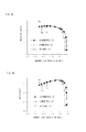
- Fig. 6A illustrates pressure ratios of the centrifugal compressor with reference to flow rates.
- the horizontal axis represents normalized values of the flow rates to the centrifugal compressor, and the vertical axis represents pressure ratios of the centrifugal compressor by rate to a reference value.
- Fig. 6B illustrates efficiency of the centrifugal compressor with reference to flow rates.
- the horizontal axis represents normalized values of the flow rates to the centrifugal compressor
- the vertical axis represents efficiency of the centrifugal compressor by rate to a reference value.
- C p denotes a constant pressure specific heat
- T 1t denotes a temperature on an inlet side of the centrifugal compressor
- T 2t denotes a temperature on an outlet side of the centrifugal compressor
- P 1t denotes a pressure on the inlet side of the centrifugal compressor
- P 2t denotes a pressure on the outlet side of the centrifugal compressor
- y denotes a ratio of specific heat
- FIG. 6A and Fig. 6B black square marks and the curve of the solid line passing through these square marks indicate the example of Embodiment 1 (i.e., the centrifugal compressor including an asymmetric casing treatment).
- the casing treatment is abbreviated as CT.
- open square marks and the curve of the dot-and-dash line passing through these square marks indicate the case of a conventional centrifugal compressor (i.e., a centrifugal compressor with a symmetric casing treatment) including a back-flow channel where the axial-direction positions of the suction ring groove 9a are constant at circumferential-direction positions.
- open round marks and the curve of the dashed line passing through these round marks indicate the case of a centrifugal compressor without a back-flow channel (i.e., a centrifugal compressor without casing treatment).
- Pa denotes a limit operating point on a small flow-rate side where surge does not occur in the example of the present invention
- Pb denotes a limit operating point on a small flow-rate side where surge does not occur in the centrifugal compressor including a symmetric casing treatment
- Pc denotes a limit operating point on a small flow-rate side where surge does not occur in the centrifugal compressor without a casing treatment.
- the centrifugal compressor including a symmetric casing treatment extends a stable operating range free from surge (flow rate range) by 7.7% from that of the centrifugal compressor without a casing treatment, and the example of the present invention further extends the stable operating range free from surge (flow rate range) by 3.3% from that of the centrifugal compressor with the symmetric casing treatment.
- the efficiency of the example of the present invention is not degraded as compared with that of the centrifugal compressor with the symmetric casing treatment.
- Embodiment 2 is the same as in the aforementioned Embodiment 1 except for the following description.
- Embodiment 2 instead of asymmetric distribution of the axial-direction positions of the suction ring groove 9a in the circumferential direction with reference to the rotational axis, in Embodiment 2, the distribution in the circumferential direction of the width of the suction ring groove 9a is asymmetric with reference to the rotational axis.
- Fig. 7A illustrates the width (i.e., the aforementioned b r ) of the suction ring groove 9a at the circumferential-direction positions to reduce the non-uniformity of fluid pressure distribution illustrated in Fig. 4 .
- the horizontal axis represents a phase angle (i.e., circumferential-direction position) around the rotational shaft 3
- the vertical axis represents a width b r of the suction ring groove 9a.
- Fig. 2 illustrates the position of 0° and the position of ⁇ .
- the suction ring groove 9a having b r as in Fig. 7A reduces the non-uniformity of the fluid pressure distribution in the circumferential direction at the pressure-distribution-to-be-modified axial-direction position. Therefore, phenomena such as fluid separation, stall and surge can be prevented more effectively. As a result, a stable operating range of the centrifugal compressor 10 can be more extended.
- Fig. 7B illustrates optimum distribution of b r obtained by numerical simulation.
- Fig. 8A illustrates pressure ratios of the centrifugal compressor with reference to flow rates.
- the horizontal axis represents normalized values of the flow rates to the centrifugal compressor, and the vertical axis represents pressure ratios of the centrifugal compressor by rate to a reference value.
- Fig. 8B illustrates efficiency of the centrifugal compressor with reference to flow rates.
- the horizontal axis represents normalized values of the flow rates to the centrifugal compressor
- the vertical axis represents efficiency of the centrifugal compressor by rate to a reference value.
- black square marks and the curve of the solid line passing through these square marks indicate the example of Embodiment 2 (i.e., the centrifugal 1 compressor including an asymmetric casing treatment).
- the casing treatment is abbreviated as CT.
- black triangle marks and the curve of the solid line passing through these triangle marks indicate the case of a conventional centrifugal compressor including a back-flow channel where the axial-direction positions of the suction ring groove 9a are constant at circumferential-direction positions (i.e., a centrifugal compressor with a symmetric casing treatment).
- open round marks and the curve of the solid line passing through these round marks indicate the case of a centrifugal compressor without a back-flow channel (i.e., a centrifugal compressor without casing treatment).
- the centrifugal compressor provided with an asymmetric casing treatment can extend a stable operating range while substantially keeping the same efficiency as compared with the centrifugal compressor provided with a symmetric casing treatment and the centrifugal compressor without a casing treatment.
Landscapes
- Engineering & Computer Science (AREA)
- Mechanical Engineering (AREA)
- General Engineering & Computer Science (AREA)
- Structures Of Non-Positive Displacement Pumps (AREA)
Abstract
Description
- The present invention relates to a centrifugal compressor including an asymmetric self-recirculating casing treatment. The centrifugal compressor is used in a turbomachinery for various purposes such as superchargers for vehicles and ships, industrial compressors and aeroengines.
- Although a turbo compressor using a centrifugal compressor has advantages such as having better efficiency, being lighter in weight and being more stable in operation than a reciprocating compressor, their allowable operating range (i.e., the range of the flow rate to a centrifugal 1 compressor) is limited. At a small flow-rate operating point of a centrifugal compressor (i.e., when the flow rate to a compressor is small), phenomena such as considerable fluid separation at the internal flow field occur, thus causing instable operation phenomena and causing stall and accordingly surge. As a result, rapid decrease in the efficiency and the pressure-ratio of the compressor is caused, the life of the compressor is shortened, and accordingly the compressor is damaged in a short time. To cope with this, various countermeasures are taken to delay instable phenomena such as stall of a compressor, extending a stable operating range.
- To extend a stable operating range, a casing treatment is provided in a centrifugal compressor. For example, as in
Patent Literatures 1 to 5, at an inner face of a casing surrounding an impeller of a centrifugal compressor are formed a suction ring groove that is located downstream of a leading edge of the impeller and a back-flow ring groove that is located upstream of the leading edge of the impeller. With this configuration, when the flow rate to the centrifugal compressor becomes small, fluid in a channel defined at the inner face of the casing is allocated to flow into the interior of the casing from the suction ring groove, and this fluid is returned to the channel upstream of the leading edge of the impeller from the back-flow ring groove. As a result, the flow rate to the impeller is increased, whereby the operation of the centrifugal compressor becomes stable. In this way, a stable operating range can be extended.
Citation List
Patent Literatures -
- PTL 1:
-
JP 3001902 - PTL 2:
-
JP-A-2007-127109 - PTL 3:
-
JP 4100030 - PTL 4:
-
JP 4107823 - PTL 5:
-
US 4930979 - Conventionally, however, non-uniform pressure distribution in the circumferential direction is not considered. That is, a scroll channel as a channel of the fluid that is sent out from an impeller of a centrifugal compressor has an asymmetric shape with reference to the rotational axis (shaft), and therefore the fluid on the outlet side of the centrifugal compressor generates non-uniform pressure distribution in the circumferential direction. This distribution affects the upstream flow field as well, causing asymmetric flow field at the inlet of the centrifugal compressor in the circumferential direction with reference to the rotational axis. In a conventional casing treatment, a suction ring groove asymmetric with reference to the rotational axis is formed, and accordingly the asymmetric flow field at the interior of the centrifugal compressor is not considered. That is, the casing treatment cannot be optimized for the entire circumference. Therefore, there is a limit to extend a stable operating range of the centrifugal compressor. In the below, the words "symmetric with reference to the rotational axis" is as "symmetric".
- Then, it is an object of the present invention to provided a centrifugal compressor including a casing treatment capable of extending a stable operating range without degrading the efficiency.
- In order to fulfill the aforementioned object, a centrifugal compressor having an asymmetric self-recirculating casing treatment of the present invention includes a rotational shaft (3) that is rotated and an impeller (5) fixed to the rotational shaft, the impeller sending out drawn fluid to an outer side of a radial direction of the rotational shaft for compression. The centrifugal compressor includes a casing (7) having an inner face surrounding the impeller. In the casing is formed a back-flow channel (9) to return fluid from a downstream position of an impeller full blade leading edge (6a) to an upstream position of the impeller full blade leading edge, and the back-flow channel includes a suction ring groove (9a) and a back-flow ring groove (9b), the suction ring groove opening at the downstream position on the inner face and formed in a circumferential direction around the rotational shaft, and the back-flow ring groove opening at the upstream position on the inner face and formed in the circumferential direction. A position in an axial direction of the rotational shaft is defined as an axial-direction position, and distribution in the circumferential direction of the axial-direction position of the suction ring groove or a width of the suction ring groove is asymmetric with reference to the rotational shaft.
In the term the "asymmetric self-recirculating casing treatment", "self-recirculating" refers to recirculation of fluid via the back-flow channel, and "asymmetric casing treatment" refers to the configuration where the circumferential-direction distribution of an axial-direction position of the suction ring groove or of the width of the suction ring groove is asymmetric with reference to the rotational shaft. - In the case where the back-flow channel is not provided, fluid pressure distribution becomes non-uniform in the circumferential direction upstream of the impeller full blade leading edge. According to the present invention, the axial-direction position of the suction ring groove or the axial-direction width of the suction ring groove is changed in accordance with circumferential-direction positions so as to reduce the non-uniformity of the fluid pressure distribution.
- According to the aforementioned present invention, the distribution in the circumferential direction of the axial-direction position of the suction ring groove or the axial-direction width of the suction ring groove is asymmetric. With this configuration, a stable operating range can be further extended without degrading the efficiency.
-
-
Fig. 1 is a vertical cross-sectional view of a centrifugal compressor according toEmbodiment 1 orEmbodiment 2 of the present invention. -
Fig. 2 is a schematic view of the centrifugal compressor ofFig. 1 viewed from an axial direction thereof. -
Fig. 3A schematically illustrates parameters of a back-flow channel according toEmbodiment 1 orEmbodiment 2. -
Fig. 3B illustrates the back-flow channel ofFig. 3A . -
Fig. 4 illustrates an exemplary distribution in the circumferential direction of fluid pressure at a casing inner face. -
Fig. 5A illustrates distribution of an axial distance Sr of a suction ring groove from an impeller full blade leading edge. -
Fig. 5B illustrates optimum distribution of an axial distance Sr of a suction ring groove from an impeller full blade leading edge. -
Fig. 6A is a graph for a comparison of pressure ratio among the centrifugal compressor provided with an asymmetric casing treatment according toEmbodiment 1, a centrifugal compressor provided with a conventional symmetric casing treatment and a centrifugal compressor without a casing treatment. -
Fig. 6B is a graph for a comparison of efficiency among the centrifugal compressor provided with an asymmetric casing treatment according toEmbodiment 1, a centrifugal compressor provided with a conventional symmetric casing treatment and a centrifugal compressor without a casing treatment. - Fig. a illustrates distribution of a width br of a suction ring groove.
-
Fig. 7B illustrates optimum distribution of a width br of a suction ring groove. -
Fig. 8A is a graph for a comparison of pressure ratio among the centrifugal compressor provided with an asymmetric casing treatment according toEmbodiment 2, a centrifugal compressor provided with a conventional symmetric casing treatment and a centrifugal compressor without a casing treatment. -
Fig. 8B is a graph for a comparison of efficiency among the centrifugal compressor provided with an asymmetric casing treatment according toEmbodiment 2, a centrifugal compressor provided with a conventional symmetric casing treatment and a centrifugal compressor without a casing treatment. - The following describes embodiments of the present invention with reference to the drawings. In the drawings, the same reference numerals are assigned to common elements, and duplicated description will be omitted.
-
Fig. 1 is a vertical cross-sectional view of acentrifugal compressor 10 including an asymmetric self-recirculating casing treatment according toEmbodiment 1 of the present invention. Thecentrifugal compressor 10 includes arotational shaft 3 that is rotated and animpeller 5 fixed to therotational shaft 3. Theimpeller 5 sends out drawn fluid to ascroll channel 4 on the outer side of a radial direction of therotational shaft 3 for compression. Theimpeller 5 includes an impellerfull blade 6 and animpeller splitter blade 8. InFig. 1 , thereference numeral 6a denotes an impeller full blade leading edge, 6b denotes an impeller full blade trailing edge, 8a denotes an impeller splitter blade leading edge, and 8b denotes an impeller splitter blade trailing edge. The leading edge refers to an upstream end, and the trailing edge refers to a downstream end.
InEmbodiment 1, the circumferential direction around therotational shaft 3 is simply called a circumferential direction, a direction in parallel with therotational shaft 3 is simply called an axial direction, a radial direction of therotational shaft 3 is simply called a radial direction, a position in the circumferential direction is simply called a circumferential-direction position, and a position in the axial direction is simply called an axial-direction position. - The
centrifugal compressor 10 further includes a casing 7 having aninner face 7a extending in the circumferential direction so as to surround the impellerfull blade 6. In the casing 7 is formed a back-flow channel 9 to return fluid from a downstream position of the impeller fullblade leading edge 6a to an upstream position of the impeller fullblade leading edge 6a. In the example ofFig. 1 , the downstream position is positioned between the impeller fullblade leading edge 6a (most upstream position in the axial direction) and the impeller fullblade trailing edge 6b (most downstream position in the axial direction). - The back-
flow channel 9 includes asuction ring groove 9a, a back-flow ring groove 9b and a ring guide channel (ring guide groove) 9c. Thesuction ring groove 9a opens at the downstream position on theinner face 7a and extends in the circumferential direction. Thesuction ring groove 9a extends in the radial direction from the opening position into the casing 7. The back-flow ring groove 9b opens at the upstream position on theinner face 7a and extends in the circumferential direction. The back-flow ring groove 9b extends in the radial direction from the opening position into the casing 7. Thering guide channel 9c extends in the axial direction so as to communicate thesuction ring groove 9a with the back-flow ring groove 9b. InFig. 1 , thering guide channel 9c is closed by ablock member 11.
InEmbodiment 1 the "ring" in thesuction ring groove 9a, the back-flow ring groove 9b and thering guide channel 9c refers to a ring shape of them viewed from the axial direction. - Due to asymmetry of the
scroll channel 4 illustrated inFig. 2 , the flow field at thesuction ring groove 9a does not have asymmetry with reference to therotational shaft 3. AlthoughFig. 1 illustrates only one side (upper side ofFig. 2 ) with reference to therotational shaft 3 as a boundary,Fig. 2 illustrates therotational shaft 3, thescroll channel 4 and the impellerfull blade 6 as a whole viewed from the axial direction. As inFig. 2 , the drawn fluid flowing into the impellerfull blade 6 is sent out by the impellerfull blade 6 to thescroll channel 4 positioned on the outer side of the radial direction, and flows to the outer side in the radial direction while flowing in the circumferential direction in thescroll channel 4. As inFig. 2 , thescroll channel 4 does not have a symmetric shape. For this reason, the flow field (pressure and flow rate of the fluid) of the fluid also does not have asymmetry in thescroll channel 4. Such asymmetric flowing field affects the flow field upstream of thescroll channel 4 as well. As a result, the flow field in thesuction ring groove 9a also does not have symmetry. - Accordingly, unlike
Embodiment 1, in the case of the configuration without the back-flow channel 9, the fluid pressure distribution in the circumferential direction becomes non-uniform at a position (e.g., at the axial-direction position of thesuction ring groove 9a, an intermediate part in the axial direction of the impelledfull blade 6 or the scroll channel 4) downstream of the impeller fullblade leading edge 6a.
UnlikeEmbodiment 1, in the case of the configuration with a back-flow channel 9 symmetric with reference to therotational shaft 3, that is, in the case where the axial-direction positions of thesuction ring groove 9a of the back-flow channel 9 are constant among the circumferential positions, the fluid pressure distribution in the circumferential direction becomes non-uniform downstream of the impeller fullblade leading edge 6a.
At a circumferential direction position of a low pressure that is downstream of the impeller fullblade leading edge 6a, the pressure becomes low also upstream of the impeller fullblade leading edge 6a. Accordingly, in many cases, the fluid pressure distribution at the position downstream of the impeller fullblade leading edge 6a is similar to that at the position upstream of the impeller fullblade leading edge 6a. - According to
Embodiment 1, the axial-direction position of thesuction ring groove 9a has asymmetric distribution in the circumferential direction with reference to therotational shaft 3.
That is, according toEmbodiment 1, the axial-direction positions of thesuction ring groove 9a at circumferential direction positions are changed in accordance with the circumferential direction positions so as to reduce non-uniformity of the fluid pressure distribution at the position (hereinafter called a pressure-distribution-to-be-modified axial-direction position) in the vicinity of theleading edge 6a upstream of the impeller fullblade leading edge 6a. Herein, the axial-direction position of the back-flow ring groove 9b may be the same as the pressure-distribution-to-be-modified axial-direction position or may be upstream of the pressure-distribution-to-be-modified axial-direction position. - The following describes embodiments of the present invention in more detail.
-
Fig. 3A illustrates parameters of the back-flow channel 9.Fig. 3B illustrates the back-flow channel ofFig. 3A . Sr corresponds to an axial-direction position of thesuction ring groove 9a, and is an axial-direction distance (axial distance) from the impeller fullblade leading edge 6a to thesuction ring groove 9a. br denotes the axial-direction width of thesuction ring groove 9a. Sf corresponds to an axial-direction position of the back-flow ring groove 9b, and is an axial distance from the impeller fullblade leading edge 6a to the back-flow ring groove 9b. bf denotes the axial-direction width of the back-flow ring groove 9b. bb denotes the radius-direction width of thering guide channel 9c. hb denotes a depth of thesuction ring groove 9a or the back-flow ring groove 9b. - Among these dimensions, Sr or br most affects the stable operating range of the
centrifugal compressor 10. That is, among these dimensions, Sr or br most affects a pressure difference between thesuction ring groove 9a and the back-flow ring groove 9b, and the flow rate of fluid at the back-flow channel 9.
Then, inEmbodiment 1, Sr is adjusted for each circumferential direction position so as to reduce non-uniformity of the fluid pressure distribution in the pressure-distribution-to-be-modified axial-direction position. -
Fig. 4 illustrates an exemplary fluid pressure distribution of the fluid in the circumferential direction at the pressure-distribution-to-be-modified axial-direction position. InFig. 4 , the horizontal axis represents a phase angle (i.e., circumferential-direction position) around therotational shaft 3, and the vertical axis represents normalized pressure of fluid. In the example ofFig. 4 , open square marks ofFig. 4 represent fluid pressures measured by an experiment. Among the phase angles ofFig. 4 , 0° is illustrated inFig. 2 . -
Fig. 5A illustrates the axial-direction positions (i.e., the aforementioned Sr) of thesuction ring groove 9a at the circumferential-direction positions to reduce the non-uniformity of fluid pressure distribution illustrated inFig. 4 . InFig. 5A , the horizontal axis represents a phase angle (i.e., circumferential-direction position) around therotational shaft 3, and the vertical axis represents an axial distance Sr from the impeller fullblade leading edge 6a to thesuction ring groove 9a. As for the phase angles ofFig. 5A ,Fig. 2 illustrates the position of 0° and the position of θ. - During operation when the flow rate to the
centrifugal compressor 10 is small, the back-flow channel 9 returns fluid partially from a position downstream of the impeller fullblade leading edge 6a to a position upstream thereof. Thereby, the flow rate drawn to the impellerfull blade 6 is increased. Accordingly the angle of attack of the impellerfull blade 6 against the fluid can be decreased, thus preventing phenomena such as fluid separation, stall and surge. As a result, a stable operating range of thecentrifugal compressor 10 can be extended.
InEmbodiment 1, thesuction ring groove 9a having Sr as inFig. 5A reduces the non-uniformity of the fluid pressure distribution in the circumferential direction at the pressure-distribution-to-be-modified axial-direction position, and therefore phenomena such as fluid separation, stall and surge can be prevented more affectively. As a result, a stable operating range of thecentrifugal compressor 10 can be more extended. -
Fig. 5B illustrates optimum distribution of Sr obtained by numerical simulation. In this numerical simulation, the parameters indicating the structure of the back-flow channel 9 are set as br=4.8 mm, Sf=15.0 mm, bf=10.0 mm, bb=13.0 mm, hb=8.0 mm and the starting phase angle θ=0°. -
Fig. 6A illustrates pressure ratios of the centrifugal compressor with reference to flow rates. InFig. 6A , the horizontal axis represents normalized values of the flow rates to the centrifugal compressor, and the vertical axis represents pressure ratios of the centrifugal compressor by rate to a reference value.
Fig. 6B illustrates efficiency of the centrifugal compressor with reference to flow rates. InFig. 6B , the horizontal axis represents normalized values of the flow rates to the centrifugal compressor, and the vertical axis represents efficiency of the centrifugal compressor by rate to a reference value. - Herein, the efficiency of the centrifugal compressor can be represented by the following Expression 1:

- In this expression, Cp denotes a constant pressure specific heat, T1t. denotes a temperature on an inlet side of the centrifugal compressor, T2t denotes a temperature on an outlet side of the centrifugal compressor, P1t denotes a pressure on the inlet side of the centrifugal compressor, P2t denotes a pressure on the outlet side of the centrifugal compressor, and y denotes a ratio of specific heat.
- In
Fig. 6A and Fig. 6B , black square marks and the curve of the solid line passing through these square marks indicate the example of Embodiment 1 (i.e., the centrifugal compressor including an asymmetric casing treatment). InFig. 6A and Fig. 6B , the casing treatment is abbreviated as CT. InFig. 6A and Fig. 6B , open square marks and the curve of the dot-and-dash line passing through these square marks indicate the case of a conventional centrifugal compressor (i.e., a centrifugal compressor with a symmetric casing treatment) including a back-flow channel where the axial-direction positions of thesuction ring groove 9a are constant at circumferential-direction positions. InFig. 6A and Fig. 6B , open round marks and the curve of the dashed line passing through these round marks indicate the case of a centrifugal compressor without a back-flow channel (i.e., a centrifugal compressor without casing treatment). - In
Fig. 6A and Fig. 6B , Pa denotes a limit operating point on a small flow-rate side where surge does not occur in the example of the present invention, Pb denotes a limit operating point on a small flow-rate side where surge does not occur in the centrifugal compressor including a symmetric casing treatment, and Pc denotes a limit operating point on a small flow-rate side where surge does not occur in the centrifugal compressor without a casing treatment. These limit operating points Pa, Pb and Pc show that the example of the present invention enables further expansion of a stable operating range. That is, the centrifugal compressor including a symmetric casing treatment extends a stable operating range free from surge (flow rate range) by 7.7% from that of the centrifugal compressor without a casing treatment, and the example of the present invention further extends the stable operating range free from surge (flow rate range) by 3.3% from that of the centrifugal compressor with the symmetric casing treatment. - As is understood from
Fig. 6B , the efficiency of the example of the present invention is not degraded as compared with that of the centrifugal compressor with the symmetric casing treatment. - The following describes a
centrifugal compressor 10 according toEmbodiment 2 of the present invention.Embodiment 2 is the same as in theaforementioned Embodiment 1 except for the following description. - Instead of asymmetric distribution of the axial-direction positions of the
suction ring groove 9a in the circumferential direction with reference to the rotational axis, inEmbodiment 2, the distribution in the circumferential direction of the width of thesuction ring groove 9a is asymmetric with reference to the rotational axis. -
Fig. 7A illustrates the width (i.e., the aforementioned br) of thesuction ring groove 9a at the circumferential-direction positions to reduce the non-uniformity of fluid pressure distribution illustrated inFig. 4 . InFig. 7A , the horizontal axis represents a phase angle (i.e., circumferential-direction position) around therotational shaft 3, and the vertical axis represents a width br of thesuction ring groove 9a. As for the phase angles ofFig. 7A ,Fig. 2 illustrates the position of 0° and the position of θ. - Similarly to
Embodiment 1, inEmbodiment 2, thesuction ring groove 9a having br as inFig. 7A reduces the non-uniformity of the fluid pressure distribution in the circumferential direction at the pressure-distribution-to-be-modified axial-direction position. Therefore, phenomena such as fluid separation, stall and surge can be prevented more effectively. As a result, a stable operating range of thecentrifugal compressor 10 can be more extended. -
Fig. 7B illustrates optimum distribution of br obtained by numerical simulation. In this numerical simulation, the parameters indicating the structure of the back-flow channel are set as Sr=5 mm, Sf=15.0 mm, bf=10.0 mm, bb=13.0 mm, hb=8.0 mm and the starting phase angle θ=0°. -
Fig. 8A illustrates pressure ratios of the centrifugal compressor with reference to flow rates. InFig. 8A , the horizontal axis represents normalized values of the flow rates to the centrifugal compressor, and the vertical axis represents pressure ratios of the centrifugal compressor by rate to a reference value.
Fig. 8B illustrates efficiency of the centrifugal compressor with reference to flow rates. InFig. 8B , the horizontal axis represents normalized values of the flow rates to the centrifugal compressor, and the vertical axis represents efficiency of the centrifugal compressor by rate to a reference value. - In
Fig. 8A and Fig. 8B , black square marks and the curve of the solid line passing through these square marks indicate the example of Embodiment 2 (i.e., the centrifugal 1 compressor including an asymmetric casing treatment). InFig. 8A and Fig. 8B , the casing treatment is abbreviated as CT. InFig. 8A and Fig. 8B , black triangle marks and the curve of the solid line passing through these triangle marks indicate the case of a conventional centrifugal compressor including a back-flow channel where the axial-direction positions of thesuction ring groove 9a are constant at circumferential-direction positions (i.e., a centrifugal compressor with a symmetric casing treatment). InFig. 8A and Fig. 8B , open round marks and the curve of the solid line passing through these round marks indicate the case of a centrifugal compressor without a back-flow channel (i.e., a centrifugal compressor without casing treatment). - As is understood from
Fig. 8A and Fig. 8B , the centrifugal compressor provided with an asymmetric casing treatment according to the example of the present invention can extend a stable operating range while substantially keeping the same efficiency as compared with the centrifugal compressor provided with a symmetric casing treatment and the centrifugal compressor without a casing treatment. - The present invention is not limited to the aforementioned embodiments, and can be modified variously in the range without departing from the scope of the present invention.
- 3: rotational shaft, 4: scroll channel, 5: impeller 6: impeller full blade, 6a: impeller full blade leading edge, 6b: impeller full blade trailing edge, 7: casing 7a: inner face of casing, 8: impeller splitter blade, 8a: impeller splitter blade leading edge, 8b: impeller splitter blade trailing edge, 9: back-flow channel, 9a: suction ring groove, 9b: back-flow ring groove, 9c: ring guide channel 10: centrifugal compressor, 11: block member
Claims (1)
- A centrifugal compressor having an asymmetric self-recirculating casing treatment, comprising a rotational shaft (3) that is rotated and an impeller (5) fixed to the rotational shaft, the impeller sending out drawn fluid to an outer side in a radial direction of the rotational shaft for compression, comprising:a casing (7) having an inner face surrounding the impeller,wherein in the casing is formed a back-flow channel (9) to return fluid from a downstream position of an impeller full blade leading edge (6a) to an upstream position of the impeller full blade leading edge,wherein the back-flow channel includes a suction ring groove (9a) and a back-flow ring groove (9b), the suction ring groove opens at the downstream position on the inner face and is formed in a circumferential direction around the rotational shaft, and the back-flow ring groove opens at the upstream position on the inner face and is formed in the circumferential direction,wherein a position in an axial direction of the rotational shaft is defined as an axial-direction position, and distribution in the circumferential direction of the axial-direction position of the suction ring groove or a width of the suction ring groove is asymmetric with reference to the rotational shaft.
Applications Claiming Priority (3)
| Application Number | Priority Date | Filing Date | Title |
|---|---|---|---|
| CN201010110311A CN101749279A (en) | 2010-02-09 | 2010-02-09 | Centrifugal compressor asymmetric self-circulation treatment casing based on varied notching width |
| CN201010110299A CN101749278A (en) | 2010-02-09 | 2010-02-09 | Centrifugal compressor asymmetric self-circulation treatment casing based on varied notching width |
| PCT/JP2011/052274 WO2011099419A1 (en) | 2010-02-09 | 2011-02-03 | Centrifugal compressor using an asymmetric self-recirculating casing treatment |
Publications (3)
| Publication Number | Publication Date |
|---|---|
| EP2535598A1 true EP2535598A1 (en) | 2012-12-19 |
| EP2535598A4 EP2535598A4 (en) | 2017-09-20 |
| EP2535598B1 EP2535598B1 (en) | 2018-06-06 |
Family
ID=44367694
Family Applications (1)
| Application Number | Title | Priority Date | Filing Date |
|---|---|---|---|
| EP11742163.6A Active EP2535598B1 (en) | 2010-02-09 | 2011-02-03 | Centrifugal compressor using an asymmetric self-recirculating casing treatment |
Country Status (4)
| Country | Link |
|---|---|
| US (1) | US9816522B2 (en) |
| EP (1) | EP2535598B1 (en) |
| JP (1) | JP5583701B2 (en) |
| WO (1) | WO2011099419A1 (en) |
Families Citing this family (10)
| Publication number | Priority date | Publication date | Assignee | Title |
|---|---|---|---|---|
| WO2011099418A1 (en) * | 2010-02-09 | 2011-08-18 | 株式会社Ihi | Centrifugal compressor using an asymmetric self-recirculating casing treatment |
| JP6237056B2 (en) | 2013-09-27 | 2017-11-29 | 株式会社Ihi | Centrifugal compressors and turbochargers |
| DE102014200588B4 (en) | 2013-12-20 | 2015-08-27 | Aktiebolaget Skf | bearing arrangement |
| JP6497183B2 (en) * | 2014-07-16 | 2019-04-10 | トヨタ自動車株式会社 | Centrifugal compressor |
| WO2019150415A1 (en) * | 2018-01-30 | 2019-08-08 | 三菱重工エンジン&ターボチャージャ株式会社 | Compressor casing, compressor provided with same, and compressor casing processing method |
| WO2021070499A1 (en) * | 2019-10-09 | 2021-04-15 | 株式会社Ihi | Centrifugal compressor |
| JP2021124069A (en) | 2020-02-06 | 2021-08-30 | 三菱重工業株式会社 | Compressor housing, compressor with compressor housing, and turbocharger with compressor |
| CN111441991B (en) * | 2020-04-03 | 2024-11-05 | 中船重工龙江广瀚燃气轮机有限公司 | An axial skew groove treatment casing with back cavity for improving compressor performance |
| JP7361214B2 (en) * | 2020-05-21 | 2023-10-13 | 三菱重工エンジン&ターボチャージャ株式会社 | Compressor housing and centrifugal compressor |
| CN114645857B (en) * | 2020-12-18 | 2025-01-07 | 麦克维尔空调制冷(苏州)有限公司 | Diffusion controllers and compressors |
Family Cites Families (20)
| Publication number | Priority date | Publication date | Assignee | Title |
|---|---|---|---|---|
| DE2920877A1 (en) | 1979-05-23 | 1980-11-27 | Bosch Gmbh Robert | ANCHOR WINDING FOR DIRECT CURRENT MACHINES AND DEVICE FOR ARRANGING THE WINDING ON THE ANCHOR |
| US4930979A (en) | 1985-12-24 | 1990-06-05 | Cummins Engine Company, Inc. | Compressors |
| CH675279A5 (en) * | 1988-06-29 | 1990-09-14 | Asea Brown Boveri | |
| DE4027174A1 (en) * | 1990-08-28 | 1992-03-05 | Kuehnle Kopp Kausch Ag | MAP STABILIZATION WITH A RADIAL COMPRESSOR |
| US6290458B1 (en) * | 1999-09-20 | 2001-09-18 | Hitachi, Ltd. | Turbo machines |
| JP3841391B2 (en) * | 2000-03-17 | 2006-11-01 | 株式会社 日立インダストリイズ | Turbo machine |
| JP4107823B2 (en) | 2001-09-28 | 2008-06-25 | 三菱重工業株式会社 | Fluid machinery |
| JP4100030B2 (en) | 2002-04-18 | 2008-06-11 | 株式会社Ihi | Centrifugal compressor |
| EP1473465B2 (en) | 2003-04-30 | 2018-08-01 | Holset Engineering Company Limited | Compressor |
| DE10355240A1 (en) * | 2003-11-26 | 2005-07-07 | Rolls-Royce Deutschland Ltd & Co Kg | Fluid flow machine with fluid removal |
| WO2007033199A2 (en) * | 2005-09-13 | 2007-03-22 | Ingersoll-Rand Company | Volute for a centrifugal compressor |
| JP4592563B2 (en) | 2005-11-07 | 2010-12-01 | 三菱重工業株式会社 | Exhaust turbocharger compressor |
| GB0600532D0 (en) * | 2006-01-12 | 2006-02-22 | Rolls Royce Plc | A blade and rotor arrangement |
| JP2007224789A (en) * | 2006-02-22 | 2007-09-06 | Toyota Motor Corp | Centrifugal compressor |
| EP1862641A1 (en) | 2006-06-02 | 2007-12-05 | Siemens Aktiengesellschaft | Annular flow channel for axial flow turbomachine |
| US20080044273A1 (en) * | 2006-08-15 | 2008-02-21 | Syed Arif Khalid | Turbomachine with reduced leakage penalties in pressure change and efficiency |
| FR2912789B1 (en) * | 2007-02-21 | 2009-10-02 | Snecma Sa | CARTER WITH CARTER TREATMENT, COMPRESSOR AND TURBOMACHINE COMPRISING SUCH A CARTER. |
| DE102008031982A1 (en) * | 2008-07-07 | 2010-01-14 | Rolls-Royce Deutschland Ltd & Co Kg | Turbomachine with groove at a trough of a blade end |
| DE102008047506A1 (en) * | 2008-09-17 | 2010-04-15 | Daimler Ag | Radial compressor, in particular for an exhaust gas turbocharger of an internal combustion engine |
| JP5948892B2 (en) | 2012-01-23 | 2016-07-06 | 株式会社Ihi | Centrifugal compressor |
-
2011
- 2011-02-03 EP EP11742163.6A patent/EP2535598B1/en active Active
- 2011-02-03 WO PCT/JP2011/052274 patent/WO2011099419A1/en active Application Filing
- 2011-02-03 US US13/578,188 patent/US9816522B2/en active Active
- 2011-02-03 JP JP2011553815A patent/JP5583701B2/en active Active
Non-Patent Citations (1)
| Title |
|---|
| See references of WO2011099419A1 * |
Also Published As
| Publication number | Publication date |
|---|---|
| EP2535598B1 (en) | 2018-06-06 |
| EP2535598A4 (en) | 2017-09-20 |
| US9816522B2 (en) | 2017-11-14 |
| JP5583701B2 (en) | 2014-09-03 |
| US20120315127A1 (en) | 2012-12-13 |
| JPWO2011099419A1 (en) | 2013-06-13 |
| WO2011099419A1 (en) | 2011-08-18 |
Similar Documents
| Publication | Publication Date | Title |
|---|---|---|
| EP2535598B1 (en) | Centrifugal compressor using an asymmetric self-recirculating casing treatment | |
| EP3564537B1 (en) | Centrifugal compressor and turbocharger | |
| US10221854B2 (en) | Impeller and rotary machine provided with same | |
| EP3536972B1 (en) | Centrifugal compressor and turbocharger | |
| EP2975269A1 (en) | Centrifugal compressor | |
| EP2535597B1 (en) | Centrifugal compressor using an asymmetric self-recirculating casing treatment | |
| EP3088700B1 (en) | Turbine | |
| EP2535596B1 (en) | Centrifugal compressor using an asymmetric self-recirculating casing treatment | |
| CN112412883B (en) | Vane diffuser and centrifugal compressor | |
| CN105275883B (en) | The manufacturing method of compressor and compressor | |
| US9976566B2 (en) | Radial compressor | |
| US11280212B2 (en) | Guide vane cascade for a turbomachine | |
| EP2657481A1 (en) | Scroll portion structure for radial turbine or diagonal flow turbine | |
| US11339797B2 (en) | Compressor scroll shape and supercharger | |
| CN107624150B (en) | Guide vane, radial compressor, exhaust gas turbocharger | |
| US10641288B2 (en) | Method for operating a compressor of a turbomachine comprising providing a plurality of stages in a front compressor area, a rear compressor area, and allowing a swirl in the rear compressor area | |
| US12228038B2 (en) | Variable geometry turbine and turbocharger | |
| CN111042870A (en) | Turbine wheel | |
| EP2535595B1 (en) | Centrifugal compressor using an asymmetric self-recirculating casing treatment | |
| US20240301803A1 (en) | Variable geometry turbine and turbocharger | |
| US11976667B2 (en) | Centrifugal compressor and turbocharger |
Legal Events
| Date | Code | Title | Description |
|---|---|---|---|
| PUAI | Public reference made under article 153(3) epc to a published international application that has entered the european phase |
Free format text: ORIGINAL CODE: 0009012 |
|
| 17P | Request for examination filed |
Effective date: 20120807 |
|
| AK | Designated contracting states |
Kind code of ref document: A1 Designated state(s): AL AT BE BG CH CY CZ DE DK EE ES FI FR GB GR HR HU IE IS IT LI LT LU LV MC MK MT NL NO PL PT RO RS SE SI SK SM TR |
|
| DAX | Request for extension of the european patent (deleted) | ||
| RA4 | Supplementary search report drawn up and despatched (corrected) |
Effective date: 20170822 |
|
| RIC1 | Information provided on ipc code assigned before grant |
Ipc: F04D 29/44 20060101AFI20170816BHEP Ipc: F04D 29/42 20060101ALI20170816BHEP Ipc: F04D 29/68 20060101ALI20170816BHEP |
|
| GRAP | Despatch of communication of intention to grant a patent |
Free format text: ORIGINAL CODE: EPIDOSNIGR1 |
|
| STAA | Information on the status of an ep patent application or granted ep patent |
Free format text: STATUS: GRANT OF PATENT IS INTENDED |
|
| INTG | Intention to grant announced |
Effective date: 20180207 |
|
| GRAS | Grant fee paid |
Free format text: ORIGINAL CODE: EPIDOSNIGR3 |
|
| GRAA | (expected) grant |
Free format text: ORIGINAL CODE: 0009210 |
|
| STAA | Information on the status of an ep patent application or granted ep patent |
Free format text: STATUS: THE PATENT HAS BEEN GRANTED |
|
| AK | Designated contracting states |
Kind code of ref document: B1 Designated state(s): AL AT BE BG CH CY CZ DE DK EE ES FI FR GB GR HR HU IE IS IT LI LT LU LV MC MK MT NL NO PL PT RO RS SE SI SK SM TR |
|
| REG | Reference to a national code |
Ref country code: GB Ref legal event code: FG4D |
|
| REG | Reference to a national code |
Ref country code: CH Ref legal event code: EP Ref country code: AT Ref legal event code: REF Ref document number: 1006402 Country of ref document: AT Kind code of ref document: T Effective date: 20180615 |
|
| REG | Reference to a national code |
Ref country code: IE Ref legal event code: FG4D |
|
| REG | Reference to a national code |
Ref country code: DE Ref legal event code: R096 Ref document number: 602011049040 Country of ref document: DE |
|
| REG | Reference to a national code |
Ref country code: NL Ref legal event code: MP Effective date: 20180606 |
|
| REG | Reference to a national code |
Ref country code: LT Ref legal event code: MG4D |
|
| PG25 | Lapsed in a contracting state [announced via postgrant information from national office to epo] |
Ref country code: CY Free format text: LAPSE BECAUSE OF FAILURE TO SUBMIT A TRANSLATION OF THE DESCRIPTION OR TO PAY THE FEE WITHIN THE PRESCRIBED TIME-LIMIT Effective date: 20180606 Ref country code: LT Free format text: LAPSE BECAUSE OF FAILURE TO SUBMIT A TRANSLATION OF THE DESCRIPTION OR TO PAY THE FEE WITHIN THE PRESCRIBED TIME-LIMIT Effective date: 20180606 Ref country code: SE Free format text: LAPSE BECAUSE OF FAILURE TO SUBMIT A TRANSLATION OF THE DESCRIPTION OR TO PAY THE FEE WITHIN THE PRESCRIBED TIME-LIMIT Effective date: 20180606 Ref country code: FI Free format text: LAPSE BECAUSE OF FAILURE TO SUBMIT A TRANSLATION OF THE DESCRIPTION OR TO PAY THE FEE WITHIN THE PRESCRIBED TIME-LIMIT Effective date: 20180606 Ref country code: BG Free format text: LAPSE BECAUSE OF FAILURE TO SUBMIT A TRANSLATION OF THE DESCRIPTION OR TO PAY THE FEE WITHIN THE PRESCRIBED TIME-LIMIT Effective date: 20180906 Ref country code: ES Free format text: LAPSE BECAUSE OF FAILURE TO SUBMIT A TRANSLATION OF THE DESCRIPTION OR TO PAY THE FEE WITHIN THE PRESCRIBED TIME-LIMIT Effective date: 20180606 Ref country code: NO Free format text: LAPSE BECAUSE OF FAILURE TO SUBMIT A TRANSLATION OF THE DESCRIPTION OR TO PAY THE FEE WITHIN THE PRESCRIBED TIME-LIMIT Effective date: 20180906 |
|
| PG25 | Lapsed in a contracting state [announced via postgrant information from national office to epo] |
Ref country code: LV Free format text: LAPSE BECAUSE OF FAILURE TO SUBMIT A TRANSLATION OF THE DESCRIPTION OR TO PAY THE FEE WITHIN THE PRESCRIBED TIME-LIMIT Effective date: 20180606 Ref country code: HR Free format text: LAPSE BECAUSE OF FAILURE TO SUBMIT A TRANSLATION OF THE DESCRIPTION OR TO PAY THE FEE WITHIN THE PRESCRIBED TIME-LIMIT Effective date: 20180606 Ref country code: GR Free format text: LAPSE BECAUSE OF FAILURE TO SUBMIT A TRANSLATION OF THE DESCRIPTION OR TO PAY THE FEE WITHIN THE PRESCRIBED TIME-LIMIT Effective date: 20180907 Ref country code: RS Free format text: LAPSE BECAUSE OF FAILURE TO SUBMIT A TRANSLATION OF THE DESCRIPTION OR TO PAY THE FEE WITHIN THE PRESCRIBED TIME-LIMIT Effective date: 20180606 |
|
| REG | Reference to a national code |
Ref country code: AT Ref legal event code: MK05 Ref document number: 1006402 Country of ref document: AT Kind code of ref document: T Effective date: 20180606 |
|
| PG25 | Lapsed in a contracting state [announced via postgrant information from national office to epo] |
Ref country code: NL Free format text: LAPSE BECAUSE OF FAILURE TO SUBMIT A TRANSLATION OF THE DESCRIPTION OR TO PAY THE FEE WITHIN THE PRESCRIBED TIME-LIMIT Effective date: 20180606 |
|
| PG25 | Lapsed in a contracting state [announced via postgrant information from national office to epo] |
Ref country code: AT Free format text: LAPSE BECAUSE OF FAILURE TO SUBMIT A TRANSLATION OF THE DESCRIPTION OR TO PAY THE FEE WITHIN THE PRESCRIBED TIME-LIMIT Effective date: 20180606 Ref country code: PL Free format text: LAPSE BECAUSE OF FAILURE TO SUBMIT A TRANSLATION OF THE DESCRIPTION OR TO PAY THE FEE WITHIN THE PRESCRIBED TIME-LIMIT Effective date: 20180606 Ref country code: CZ Free format text: LAPSE BECAUSE OF FAILURE TO SUBMIT A TRANSLATION OF THE DESCRIPTION OR TO PAY THE FEE WITHIN THE PRESCRIBED TIME-LIMIT Effective date: 20180606 Ref country code: SK Free format text: LAPSE BECAUSE OF FAILURE TO SUBMIT A TRANSLATION OF THE DESCRIPTION OR TO PAY THE FEE WITHIN THE PRESCRIBED TIME-LIMIT Effective date: 20180606 Ref country code: RO Free format text: LAPSE BECAUSE OF FAILURE TO SUBMIT A TRANSLATION OF THE DESCRIPTION OR TO PAY THE FEE WITHIN THE PRESCRIBED TIME-LIMIT Effective date: 20180606 Ref country code: EE Free format text: LAPSE BECAUSE OF FAILURE TO SUBMIT A TRANSLATION OF THE DESCRIPTION OR TO PAY THE FEE WITHIN THE PRESCRIBED TIME-LIMIT Effective date: 20180606 Ref country code: IS Free format text: LAPSE BECAUSE OF FAILURE TO SUBMIT A TRANSLATION OF THE DESCRIPTION OR TO PAY THE FEE WITHIN THE PRESCRIBED TIME-LIMIT Effective date: 20181006 |
|
| PG25 | Lapsed in a contracting state [announced via postgrant information from national office to epo] |
Ref country code: SM Free format text: LAPSE BECAUSE OF FAILURE TO SUBMIT A TRANSLATION OF THE DESCRIPTION OR TO PAY THE FEE WITHIN THE PRESCRIBED TIME-LIMIT Effective date: 20180606 Ref country code: IT Free format text: LAPSE BECAUSE OF FAILURE TO SUBMIT A TRANSLATION OF THE DESCRIPTION OR TO PAY THE FEE WITHIN THE PRESCRIBED TIME-LIMIT Effective date: 20180606 |
|
| REG | Reference to a national code |
Ref country code: DE Ref legal event code: R097 Ref document number: 602011049040 Country of ref document: DE |
|
| PLBE | No opposition filed within time limit |
Free format text: ORIGINAL CODE: 0009261 |
|
| STAA | Information on the status of an ep patent application or granted ep patent |
Free format text: STATUS: NO OPPOSITION FILED WITHIN TIME LIMIT |
|
| 26N | No opposition filed |
Effective date: 20190307 |
|
| PG25 | Lapsed in a contracting state [announced via postgrant information from national office to epo] |
Ref country code: SI Free format text: LAPSE BECAUSE OF FAILURE TO SUBMIT A TRANSLATION OF THE DESCRIPTION OR TO PAY THE FEE WITHIN THE PRESCRIBED TIME-LIMIT Effective date: 20180606 Ref country code: DK Free format text: LAPSE BECAUSE OF FAILURE TO SUBMIT A TRANSLATION OF THE DESCRIPTION OR TO PAY THE FEE WITHIN THE PRESCRIBED TIME-LIMIT Effective date: 20180606 |
|
| REG | Reference to a national code |
Ref country code: CH Ref legal event code: PL |
|
| PG25 | Lapsed in a contracting state [announced via postgrant information from national office to epo] |
Ref country code: LU Free format text: LAPSE BECAUSE OF NON-PAYMENT OF DUE FEES Effective date: 20190203 Ref country code: MC Free format text: LAPSE BECAUSE OF FAILURE TO SUBMIT A TRANSLATION OF THE DESCRIPTION OR TO PAY THE FEE WITHIN THE PRESCRIBED TIME-LIMIT Effective date: 20180606 |
|
| REG | Reference to a national code |
Ref country code: BE Ref legal event code: MM Effective date: 20190228 |
|
| REG | Reference to a national code |
Ref country code: IE Ref legal event code: MM4A |
|
| PG25 | Lapsed in a contracting state [announced via postgrant information from national office to epo] |
Ref country code: AL Free format text: LAPSE BECAUSE OF FAILURE TO SUBMIT A TRANSLATION OF THE DESCRIPTION OR TO PAY THE FEE WITHIN THE PRESCRIBED TIME-LIMIT Effective date: 20180606 |
|
| PG25 | Lapsed in a contracting state [announced via postgrant information from national office to epo] |
Ref country code: CH Free format text: LAPSE BECAUSE OF NON-PAYMENT OF DUE FEES Effective date: 20190228 Ref country code: LI Free format text: LAPSE BECAUSE OF NON-PAYMENT OF DUE FEES Effective date: 20190228 |
|
| PG25 | Lapsed in a contracting state [announced via postgrant information from national office to epo] |
Ref country code: IE Free format text: LAPSE BECAUSE OF NON-PAYMENT OF DUE FEES Effective date: 20190203 |
|
| PG25 | Lapsed in a contracting state [announced via postgrant information from national office to epo] |
Ref country code: BE Free format text: LAPSE BECAUSE OF NON-PAYMENT OF DUE FEES Effective date: 20190228 Ref country code: FR Free format text: LAPSE BECAUSE OF NON-PAYMENT OF DUE FEES Effective date: 20190228 |
|
| PG25 | Lapsed in a contracting state [announced via postgrant information from national office to epo] |
Ref country code: TR Free format text: LAPSE BECAUSE OF FAILURE TO SUBMIT A TRANSLATION OF THE DESCRIPTION OR TO PAY THE FEE WITHIN THE PRESCRIBED TIME-LIMIT Effective date: 20180606 |
|
| PG25 | Lapsed in a contracting state [announced via postgrant information from national office to epo] |
Ref country code: PT Free format text: LAPSE BECAUSE OF FAILURE TO SUBMIT A TRANSLATION OF THE DESCRIPTION OR TO PAY THE FEE WITHIN THE PRESCRIBED TIME-LIMIT Effective date: 20181008 Ref country code: MT Free format text: LAPSE BECAUSE OF NON-PAYMENT OF DUE FEES Effective date: 20190203 |
|
| PG25 | Lapsed in a contracting state [announced via postgrant information from national office to epo] |
Ref country code: HU Free format text: LAPSE BECAUSE OF FAILURE TO SUBMIT A TRANSLATION OF THE DESCRIPTION OR TO PAY THE FEE WITHIN THE PRESCRIBED TIME-LIMIT; INVALID AB INITIO Effective date: 20110203 |
|
| PG25 | Lapsed in a contracting state [announced via postgrant information from national office to epo] |
Ref country code: MK Free format text: LAPSE BECAUSE OF FAILURE TO SUBMIT A TRANSLATION OF THE DESCRIPTION OR TO PAY THE FEE WITHIN THE PRESCRIBED TIME-LIMIT Effective date: 20180606 |
|
| PGFP | Annual fee paid to national office [announced via postgrant information from national office to epo] |
Ref country code: DE Payment date: 20240226 Year of fee payment: 14 Ref country code: GB Payment date: 20240221 Year of fee payment: 14 |