WO2020195604A1 - 車両の走行制御装置 - Google Patents
車両の走行制御装置 Download PDFInfo
- Publication number
- WO2020195604A1 WO2020195604A1 PCT/JP2020/008884 JP2020008884W WO2020195604A1 WO 2020195604 A1 WO2020195604 A1 WO 2020195604A1 JP 2020008884 W JP2020008884 W JP 2020008884W WO 2020195604 A1 WO2020195604 A1 WO 2020195604A1
- Authority
- WO
- WIPO (PCT)
- Prior art keywords
- steering
- turning
- steering angle
- state amount
- control
- Prior art date
- Legal status (The legal status is an assumption and is not a legal conclusion. Google has not performed a legal analysis and makes no representation as to the accuracy of the status listed.)
- Ceased
Links
Images

Classifications
-
- B—PERFORMING OPERATIONS; TRANSPORTING
- B62—LAND VEHICLES FOR TRAVELLING OTHERWISE THAN ON RAILS
- B62D—MOTOR VEHICLES; TRAILERS
- B62D6/00—Arrangements for automatically controlling steering depending on driving conditions sensed and responded to, e.g. control circuits
-
- B—PERFORMING OPERATIONS; TRANSPORTING
- B60—VEHICLES IN GENERAL
- B60W—CONJOINT CONTROL OF VEHICLE SUB-UNITS OF DIFFERENT TYPE OR DIFFERENT FUNCTION; CONTROL SYSTEMS SPECIALLY ADAPTED FOR HYBRID VEHICLES; ROAD VEHICLE DRIVE CONTROL SYSTEMS FOR PURPOSES NOT RELATED TO THE CONTROL OF A PARTICULAR SUB-UNIT
- B60W30/00—Purposes of road vehicle drive control systems not related to the control of a particular sub-unit, e.g. of systems using conjoint control of vehicle sub-units
- B60W30/10—Path keeping
-
- B—PERFORMING OPERATIONS; TRANSPORTING
- B60—VEHICLES IN GENERAL
- B60W—CONJOINT CONTROL OF VEHICLE SUB-UNITS OF DIFFERENT TYPE OR DIFFERENT FUNCTION; CONTROL SYSTEMS SPECIALLY ADAPTED FOR HYBRID VEHICLES; ROAD VEHICLE DRIVE CONTROL SYSTEMS FOR PURPOSES NOT RELATED TO THE CONTROL OF A PARTICULAR SUB-UNIT
- B60W10/00—Conjoint control of vehicle sub-units of different type or different function
- B60W10/18—Conjoint control of vehicle sub-units of different type or different function including control of braking systems
-
- B—PERFORMING OPERATIONS; TRANSPORTING
- B60—VEHICLES IN GENERAL
- B60W—CONJOINT CONTROL OF VEHICLE SUB-UNITS OF DIFFERENT TYPE OR DIFFERENT FUNCTION; CONTROL SYSTEMS SPECIALLY ADAPTED FOR HYBRID VEHICLES; ROAD VEHICLE DRIVE CONTROL SYSTEMS FOR PURPOSES NOT RELATED TO THE CONTROL OF A PARTICULAR SUB-UNIT
- B60W10/00—Conjoint control of vehicle sub-units of different type or different function
- B60W10/20—Conjoint control of vehicle sub-units of different type or different function including control of steering systems
-
- B—PERFORMING OPERATIONS; TRANSPORTING
- B60—VEHICLES IN GENERAL
- B60W—CONJOINT CONTROL OF VEHICLE SUB-UNITS OF DIFFERENT TYPE OR DIFFERENT FUNCTION; CONTROL SYSTEMS SPECIALLY ADAPTED FOR HYBRID VEHICLES; ROAD VEHICLE DRIVE CONTROL SYSTEMS FOR PURPOSES NOT RELATED TO THE CONTROL OF A PARTICULAR SUB-UNIT
- B60W30/00—Purposes of road vehicle drive control systems not related to the control of a particular sub-unit, e.g. of systems using conjoint control of vehicle sub-units
- B60W30/02—Control of vehicle driving stability
- B60W30/045—Improving turning performance
-
- B—PERFORMING OPERATIONS; TRANSPORTING
- B62—LAND VEHICLES FOR TRAVELLING OTHERWISE THAN ON RAILS
- B62D—MOTOR VEHICLES; TRAILERS
- B62D15/00—Steering not otherwise provided for
- B62D15/02—Steering position indicators ; Steering position determination; Steering aids
- B62D15/025—Active steering aids, e.g. helping the driver by actively influencing the steering system after environment evaluation
-
- B—PERFORMING OPERATIONS; TRANSPORTING
- B62—LAND VEHICLES FOR TRAVELLING OTHERWISE THAN ON RAILS
- B62D—MOTOR VEHICLES; TRAILERS
- B62D7/00—Steering linkage; Stub axles or their mountings
- B62D7/06—Steering linkage; Stub axles or their mountings for individually-pivoted wheels, e.g. on king-pins
- B62D7/14—Steering linkage; Stub axles or their mountings for individually-pivoted wheels, e.g. on king-pins the pivotal axes being situated in more than one plane transverse to the longitudinal centre line of the vehicle, e.g. all-wheel steering
-
- B—PERFORMING OPERATIONS; TRANSPORTING
- B62—LAND VEHICLES FOR TRAVELLING OTHERWISE THAN ON RAILS
- B62D—MOTOR VEHICLES; TRAILERS
- B62D5/00—Power-assisted or power-driven steering
- B62D5/008—Changing the transfer ratio between the steering wheel and the steering gear by variable supply of energy, e.g. by using a superposition gear
-
- B—PERFORMING OPERATIONS; TRANSPORTING
- B62—LAND VEHICLES FOR TRAVELLING OTHERWISE THAN ON RAILS
- B62D—MOTOR VEHICLES; TRAILERS
- B62D6/00—Arrangements for automatically controlling steering depending on driving conditions sensed and responded to, e.g. control circuits
- B62D6/002—Arrangements for automatically controlling steering depending on driving conditions sensed and responded to, e.g. control circuits computing target steering angles for front or rear wheels
-
- B—PERFORMING OPERATIONS; TRANSPORTING
- B62—LAND VEHICLES FOR TRAVELLING OTHERWISE THAN ON RAILS
- B62D—MOTOR VEHICLES; TRAILERS
- B62D7/00—Steering linkage; Stub axles or their mountings
- B62D7/06—Steering linkage; Stub axles or their mountings for individually-pivoted wheels, e.g. on king-pins
- B62D7/14—Steering linkage; Stub axles or their mountings for individually-pivoted wheels, e.g. on king-pins the pivotal axes being situated in more than one plane transverse to the longitudinal centre line of the vehicle, e.g. all-wheel steering
- B62D7/15—Steering linkage; Stub axles or their mountings for individually-pivoted wheels, e.g. on king-pins the pivotal axes being situated in more than one plane transverse to the longitudinal centre line of the vehicle, e.g. all-wheel steering characterised by means varying the ratio between the steering angles of the steered wheels
- B62D7/159—Steering linkage; Stub axles or their mountings for individually-pivoted wheels, e.g. on king-pins the pivotal axes being situated in more than one plane transverse to the longitudinal centre line of the vehicle, e.g. all-wheel steering characterised by means varying the ratio between the steering angles of the steered wheels characterised by computing methods or stabilisation processes or systems, e.g. responding to yaw rate, lateral wind, load, road condition
Definitions
- the present invention relates to a vehicle travel control device.
- Patent Document 1 describes an example of a traveling control device that implements turning support control that supports turning of a vehicle traveling in a traveling lane.
- this driving control device when the vehicle is turned in a situation where the driver is not steering, the vehicle is turned by automatically adjusting the steering angle of the front wheels connected to the steering device. There is.
- the neutral point is the steering angle when the steering angle of the front wheels is "0 (zero)".
- the holding torque which is the torque for holding the steering angle at the neutral point, is applied to the steering wheel by driving the steering device.
- the magnitude of the holding torque changes depending on the vehicle body slip angle and the front wheel steering angle. Therefore, it is necessary to sequentially update the holding torque according to changes in the vehicle body slip angle and the steering angle of the front wheels.
- the first torque which is a component corresponding to the vehicle body slip angle
- the second torque which is a component corresponding to the steering angle of the front wheels
- the vehicle travel control device for solving the above problems includes a front wheel steering angle adjusting device that controls a turning state amount, which is a state amount related to the turning of the vehicle, and a front wheel steering angle adjusting device by adjusting the steering angle of the front wheels. It is applied to a vehicle separately provided with a turning control device for controlling the turning state amount, a steering wheel for which steering torque is input, and a steering device connected to the front wheels. By driving at least one of the front wheel steering angle adjusting device and the turning control device, the traveling control device causes the turning state amount to follow the target turning state amount which is the target of the turning state amount.
- a turning control unit that executes turning support control and a holding torque that is a torque for holding the steering angle of the steering wheel at a neutral point are derived and held when the steering is not being steered while the turning support control is being performed. It includes a steering instruction unit that instructs the steering device to apply torque to the steering wheel. Then, in the turning support control when steering is not performed, the turning control unit drives the turning control device but does not drive the front wheel steering angle adjusting device, and steering is performed. In the turning support control, the front wheel steering angle adjusting device is driven.
- the front wheel steering angle adjusting device when the steering is not performed during the turning support control, the front wheel steering angle adjusting device is not driven, so that the steering angle of the front wheels is maintained at "0 (zero)". Therefore, when deriving the holding torque, it is necessary to derive the torque component according to the vehicle body slip angle, but it is not necessary to derive the torque component according to the steering angle of the front wheels. Therefore, since it is not necessary to derive the torque component according to the steering angle of the front wheels, the steering angle of the steering wheel can be maintained at the neutral point while suppressing an increase in the calculation load of the traveling control device. Become.
- FIG. 1 which shows the functional configuration of the travel control device of the vehicle of embodiment, and the schematic configuration of the vehicle provided with the travel control device.
- FIG. 1 schematically illustrates a vehicle equipped with the travel control device 70 of the present embodiment.
- the vehicle includes a front wheel steering angle adjusting device 10 that adjusts the steering angles ⁇ F of a plurality of front wheels FL and FR, a steering device 20 that is connected to the front wheels FL and FR, and steering of a plurality of rear wheels RL and RR.
- a rear wheel steering angle adjusting device 30 for adjusting the angle ⁇ R is provided.
- the steering angle ⁇ F of the front wheels FL and FR is referred to as “front wheel steering angle ⁇ F”, and the steering angle ⁇ R of the rear wheels RL and RR is referred to as “rear wheel steering angle ⁇ R”.
- the vehicle includes a braking device 40 for adjusting the braking force of the vehicle and a driving device 50 for adjusting the driving force of the vehicle.
- the front wheel steering angle adjusting device 10 includes a front wheel steering actuator 11 and a front wheel steering control unit 16 that controls the front wheel steering actuator 11.
- the front wheel steering actuator 11 is connected to the front wheels FL and FR via a tie rod 13.
- the front wheel steering actuator 11 is provided with a front wheel motor 12 as a power source, and the front wheel motor 12 is controlled by the front wheel steering control unit 16. Then, the front wheel steering angle adjusting device 10 adjusts the front wheel steering angle ⁇ F by transmitting the driving torque of the front wheel motor 12 to the front wheels FL and FR via the tie rod 13.
- the steering device 20 includes a steering wheel 21, a steering actuator 22, and a steering control unit 26 that controls the steering actuator 22. Since the steering wheel 21 is operated by the driver, the steering torque TQIn caused by steering is input.
- the steering actuator 22 is connected to the steering wheel 21 via the steering shaft 23, and is also connected to the front wheel steering actuator 11 via the intermediate shaft 24. That is, the steering actuator 22 is connected to the front wheels FL and FR via the intermediate shaft 24, the front wheel steering actuator 11, and the tie rod 13.
- the steering torque TQIn input to the steering wheel 21 by the driver is input to the front wheel steering actuator 11 via the steering actuator 22.
- the front wheel steering angle ⁇ F is changed according to the change in the steering angle of the steering wheel 21. That is, when steering is performed, there is a correlation between the actual steering angle Str and the front wheel steering angle ⁇ F.
- the steering angle Str that correlates with the front wheel steering angle ⁇ F is called “reference steering angle StrB”.
- the actual steering angle Str is substantially the same as the reference steering angle StrB at that time.
- the reference steering angle StrB when the front wheel steering angle ⁇ F is “0 (zero)” is referred to as “neutral point StrC”.
- the steering actuator 22 has an operating angle control mechanism 221 that adjusts the difference between the actual steering angle Str and the reference steering angle StrB, and a steering motor 222 that is a power source of the operating angle control mechanism 221.
- an operating angle control mechanism 221 that adjusts the difference between the actual steering angle Str and the reference steering angle StrB
- a steering motor 222 that is a power source of the operating angle control mechanism 221.
- the steering device 20 is provided with a steering angle sensor 101 for detecting the steering angle Str and a torque sensor 102 for detecting the steering torque TQIn input to the steering wheel 21 by steering.
- the steering angle sensor 101 outputs a signal corresponding to the steering angle Str as a detection signal to the steering control unit 26 and the traveling control device 70.
- the torque sensor 102 outputs a signal corresponding to the steering torque TQIn to the steering control unit 26 and the travel control device 70 as a detection signal.
- the rear wheel steering angle adjusting device 30 has a rear wheel steering actuator 31 and a rear wheel steering control unit 36 that controls the rear wheel steering actuator 31.
- the rear wheel steering actuator 31 is connected to each of the rear wheels RL and RR via a tie rod 33.
- the rear wheel steering actuator 31 is provided with a rear wheel motor 32 as a power source, and the rear wheel motor 32 is controlled by the rear wheel steering control unit 36. Then, the rear wheel steering angle adjusting device 30 adjusts the rear wheel steering angle ⁇ R by transmitting the driving torque of the rear wheel motor 32 to the rear wheels RL and RR via the tie rod 33.
- the rear wheel steering angle ⁇ R is changed while the vehicle is running in this way, the magnitude of the yaw moment of the vehicle changes.
- the rear wheel steering angle adjusting device 30 is an example of the “turning control device”.
- the braking device 40 has a braking actuator 41 and a braking control unit 46 that controls the braking actuator 41.
- the braking actuator 41 can individually adjust the braking force of each wheel FL, FR, RL, RR.
- a yaw moment can be generated in the vehicle by generating a braking force difference between the right front wheel FR and the left front wheel FL, that is, the turning state amount can be changed. Therefore, in this embodiment, the braking device 40 is also an example of the "turning control device".
- the drive device 50 has a power unit 51 and a drive control unit 56 that controls the power unit 51.
- the power unit 51 is provided with a power source for a vehicle such as an engine or an electric motor.
- a power source for a vehicle such as an engine or an electric motor.
- the drive torque output from the drive device 50 is input to the rear wheels RL and RR.
- the travel control device 70 supports the automatic travel of the vehicle according to the set travel route TR by driving various in-vehicle devices.
- information regarding a travel path TR for traveling the vehicle along the travel lane is input to the travel control device 70 from another device, for example.
- the travel control device 70 has a steering determination unit 71, a turning control unit 72, a steering instruction unit 73, a required turning state amount setting unit 74, and a target automatic turning state amount as functional units for supporting the turning of the vehicle. It has a setting unit 75 and a target turning state quantity derivation unit 76.
- the steering determination unit 71 determines whether or not the driver is steering. For example, the steering determination unit 71 uses the steering torque TQIn derived based on the detection signal from the torque sensor 102 to determine whether or not steering is being performed. The process of determining whether or not steering is being performed will be described later.
- the turning control unit 72 drives at least one of the front wheel steering angle adjusting device 10, the rear wheel steering angle adjusting device 30, and the braking device 40 to drive the target turning state amount TSQTr, which is the target of the turning state amount TSQ.
- the turning support control for following the turning state quantity TSQ is performed.
- the turning state quantity TSQ is a state quantity in which a larger yaw moment can be generated as the value is larger.
- the turning state quantity TSQ for example, the yaw rate Yr of the vehicle derived based on the detection signal from the yaw rate sensor 103 and the lateral acceleration Gy of the vehicle derived based on the detection signal from the lateral acceleration sensor 104 are used. Can be mentioned.
- the turning control unit 72 executes steering-time turning support control as turning support control when steering is being performed. On the other hand, when the steering determination unit 71 has not determined that steering is being performed, the turning control unit 72 performs non-steering turning support control as turning support control when steering is not performed.
- the turning control unit 72 drives the front wheel steering angle adjusting device 10 and at least one of the rear wheel steering angle adjusting device 30 and the braking device 40 in the turning support control during steering. On the other hand, the turning control unit 72 drives at least one of the rear wheel steering angle adjusting device 30 and the braking device 40 in the non-steering turning support control, but does not drive the front wheel steering angle adjusting device 10.
- the front wheel steering control unit 16 controls the front wheel steering actuator 11 in order to change the front wheel steering angle ⁇ F.
- the drive instruction is not input to the front wheel steering angle adjusting device 10, so that the front wheel steering angle ⁇ F of the front wheel steering control unit 16 is “0 (zero)”. ) ”,
- the front wheel steering actuator 11 is controlled. That is, not driving the front wheel steering angle adjusting device 10 when the steering turning support control is performed means that the front wheel steering angle ⁇ F is maintained at “0 (zero)”.
- the rear wheel steering control unit 36 rears the rear wheels to change the steering angle ⁇ R. It controls the wheel steering actuator 31.
- the rear wheel steering control unit 36 has a rear wheel steering angle ⁇ R of “0”.
- the rear wheel steering actuator 31 is controlled so as to be maintained at. That is, driving the rear wheel steering angle adjusting device 30 in the turning support control means turning the vehicle by adjusting the rear wheel steering angle ⁇ R.
- not driving the rear wheel steering angle adjusting device 30 in the turning support control means maintaining the rear wheel steering angle ⁇ R at “0 (zero)”.
- the braking control unit 46 causes a braking force difference between the right front wheel FR and the left front wheel FL.
- the braking actuator 41 is controlled so as to do so.
- the braking control unit 46 causes a braking force difference between the right front wheel FR and the left front wheel FL. Does not occur. That is, driving the braking device 40 in the turning support control means turning the vehicle by adjusting the difference in braking force between the right wheel and the left wheel. On the other hand, not driving the braking device 40 in the turning support control means maintaining the braking force difference at "0 (zero)".
- the vehicle may decelerate. Therefore, when the braking device 40 is driven by implementing the turning support control, the turning control unit 72 offsets the deceleration of the vehicle caused by applying the braking force to at least one of the right front wheel FR and the left front wheel FL.
- the drive control unit 56 may be instructed to increase the driving force of the vehicle. In this case, the drive control unit 56 controls the power unit 51 so that when the instruction is input, the driving force of the vehicle is increased by the amount corresponding to the instruction.
- the steering instruction unit 73 controls the steering device 20 when the turning support control is being performed by the turning control unit 72. That is, the steering instruction unit 73 instructs the steering device 20 to maintain the steering angle at the neutral point StrC when the non-steering turning support control is implemented. On the other hand, the steering instruction unit 73 instructs the steering device 20 to assist the driver in steering when the steering support control during steering is implemented.
- the processing content of the steering instruction unit 73 when the non-steering turning support control is implemented and the processing content of the steering instruction unit 73 when the steering rotation support control is implemented will be described later.
- the required turning state amount setting unit 74 acquires the steering-related value related to steering, and sets a value corresponding to the steering-related value as the required turning state amount, which is the required value of the turning state amount.
- the steering-related value include a steering angle Str and a steering torque TQIn.
- the required turning state amount setting unit 74 sets the required turning state amount TSQR so that the larger the steering angle Str, the larger the value.
- the required turning state amount setting unit 74 equalizes the required turning state amount TSQR to "0 (zero)".
- the turning state quantity TSQ is the yaw rate Yr of the vehicle, the yaw rate Yr corresponding to the steering-related value is set as the required turning state quantity TSQR.
- the target automatic turning state amount setting unit 75 sets the target automatic turning state amount TSQATr, which is the target of the turning state amount for turning the vehicle according to the set travel path TR. For example, the target automatic turning state amount setting unit 75 sets the target automatic turning state amount TSQATr so that the smaller the turning radius of the traveling path TR, the larger the value.
- the turning state amount TSQ is the yaw rate Yr of the vehicle
- the yaw rate Yr corresponding to the turning radius of the traveling path TR and the vehicle body speed is set as the target automatic turning state amount TSQATr.
- the target turning state quantity deriving unit 76 derives the target turning state quantity TSQTr. That is, when it is not determined by the steering determination unit 71 that steering is being performed, the target turning state amount deriving unit 76 sets the target automatic turning state amount TSQATr as the target turning state amount TSQTr. On the other hand, when it is determined by the steering determination unit 71 that steering is being performed, the target turning state amount deriving unit 76 has an absolute value of the required turning state amount TSQR and the target automatic turning state amount TSQATr. The target turning state quantity TSQTr is derived based on the larger parameter.
- the target turning state quantity deriving unit 76 derives the target turning state quantity TSQTr so that the larger the parameter, the larger the value. For example, the target turning state amount deriving unit 76 sets the parameter having the larger absolute value of the required turning state amount TSQR and the target automatic turning state amount TSQATr as the target turning state amount TSQTr.
- the target turning state quantity derivation unit 76 also derives the target vehicle body slip angle ⁇ Tr, which is the target of the vehicle body slip angle.
- the target turning state amount deriving unit 76 derives the target vehicle body slip angle ⁇ Tr based on the derived target turning state amount TSQTr.
- This processing routine is repeatedly executed every predetermined control cycle when the turning support control is implemented.
- step S11 it is determined whether or not the absolute value of the steering torque TQIn is equal to or greater than the determination steering torque TQInTh.
- the determination steering torque TQInTh is a criterion for determining whether or not the driver has the intention to rotate the steering wheel 21.
- step S12 the steering override flag FLG1 is set to ON.
- the steering override flag FLG1 is a flag that is set to on when steering is being performed during turning support control, while is set to off when steering is not being performed during turning support control. .. Then, this processing routine is temporarily terminated.
- step S11 when the absolute value
- This processing routine is repeatedly executed every predetermined control cycle when the execution condition of the turning support control is satisfied.
- the implementation condition includes that the travel route TR is set and the execution of vehicle control according to the travel route TR is permitted.
- step S21 it is determined whether or not the steering override flag FLG1 is set to off.
- the non-steering turning support control including steps S22 to S26 is executed. That is, in the non-steering turning support control, in step S22, it is determined whether or not the vehicle is approaching the boundary line of the traveling lane.
- the boundary line is a line located at the side end of the traveling lane. Whether or not the vehicle is approaching the boundary line can be determined by analyzing an image obtained by an image pickup device that images the front of the vehicle. If the vehicle is close to the boundary line, there is a concern that the vehicle may deviate from the driving lane.
- step S23 the control amount DRR of the rear wheel steering angle adjusting device 30 is derived based on the deviation between the target turning state amount TSQTr and the turning state amount TSQ derived by the target turning state amount deriving unit 76.
- step S24 an output process for outputting the control amount to each control unit is executed. In the output process in this case, the control amount DRR derived in step S23 is output to the rear wheel steering control unit 36.
- the rear wheel steering angle adjusting device 30 controls the rear wheel steering actuator 31 based on the input control amount DRR. Therefore, the rear wheel steering angle ⁇ R becomes the steering angle according to the control amount DRR.
- the control amount DRBa input to the braking device 40 is "0 (zero)"
- the braking device 40 does not generate a braking force difference between the right front wheel FR and the left front wheel FL.
- the control amount DRF input to the front wheel steering angle adjusting device 10 is “0 (zero)”
- the front wheel steering angle adjusting device 10 maintains the front wheel steering angle ⁇ F at “0 (zero)”. That is, while the rear wheel steering angle adjusting device 30 is driven, the front wheel steering angle adjusting device 10 and the braking control unit 46 are not driven.
- step S22 determines whether the vehicle is approaching the boundary line of the traveling lane (YES). If it is determined in step S22 that the vehicle is approaching the boundary line of the traveling lane (YES), the process proceeds to the next step S25.
- step S25 the control amount DRR of the rear wheel steering angle adjusting device 30 and the control amount of the braking device 40 are based on the deviation between the target turning state amount TSQTr derived by the target turning state amount deriving unit 76 and the turning state amount TSQ.
- DRBa is derived.
- the control amount DRR of the rear wheel steering angle adjusting device 30 is a value corresponding to the deviation between the target turning state amount TSQTr and the turning state amount TSQ. Is set. Then, when the vehicle shifts from the state in which it is not determined that the vehicle is approaching the boundary line to the state in which the determination is made, the control amount DRR of the rear wheel steering angle adjusting device 30 is maintained at the value before the shift. Rudder.
- control amount DRBa of the braking device 40 based on the deviation between the target turning state amount TSQTr and the turning state amount TSQ.
- a value capable of correcting the deviation between the lateral center of the vehicle and the lateral center of the traveling lane is set.
- step S26 an output process for outputting the control amount to each control unit is executed.
- the control amount DRR derived in step S25 is output to the rear wheel steering control unit 36, and the control amount DRBa is output to the braking control unit 46.
- "0 (zero)" is output to the front wheel steering control unit 16 as the control amount DRF of the front wheel steering angle adjusting device 10. Then, this processing routine is temporarily terminated.
- the rear wheel steering angle adjusting device 30 controls the rear wheel steering actuator 31 based on the input control amount DRR. Therefore, the rear wheel steering angle ⁇ R becomes the steering angle according to the control amount DRR. Further, in the braking device 40, the braking actuator 41 is controlled based on the input control amount DRBa. Therefore, a braking force difference is generated between the right front wheel FR and the left front wheel FL according to the control amount DRBa.
- the control amount DRF input to the front wheel steering angle adjusting device 10 is “0 (zero)”
- the front wheel steering angle adjusting device 10 maintains the front wheel steering angle ⁇ F at “0 (zero)”. That is, while the rear wheel steering angle adjusting device 30 and the braking device 40 are driven, the front wheel steering angle adjusting device 10 is not driven.
- step S21 when the steering override flag FLG1 is set to ON (NO), it is determined that steering is being performed. Therefore, steering support control including steps S27 to S29 Is carried out. That is, in the steering turning support control, the vehicle body slip angle ⁇ is derived in step S27.
- the vehicle body slip angle ⁇ can be derived, for example, based on the front wheel steering angle ⁇ F and the rear wheel steering angle ⁇ R. That is, the vehicle body slip angle ⁇ can be controlled by adjusting the front wheel steering angle ⁇ F and the rear wheel steering angle ⁇ R.
- the front wheel steering angle is based on the target turning state quantity TSQTr derived by the target turning state quantity deriving unit 76, the deviation between the target vehicle body slip angle ⁇ Tr and the vehicle body slip angle ⁇ , and the steering angle Str.
- the control amount DRF of the adjusting device 10, the control amount DRR of the rear wheel steering angle adjusting device 30, and the control amount DRBa of the braking device 40 are derived.
- a value corresponding to the steering angle Str is set as the control amount DRF of the front wheel steering angle adjusting device 10.
- the control amount DRR of the rear wheel steering angle adjusting device 30 a value corresponding to the deviation between the target vehicle body slip angle ⁇ Tr and the vehicle body slip angle ⁇ is set.
- the predicted value of the turning state amount when the front wheel steering angle adjusting device 10 and the rear wheel steering angle adjusting device 30 are controlled based on the control amounts DRF and DRR, and the value corresponding to the deviation from the target turning state amount TSQTr are obtained. It is derived as the control amount DRBa of the braking device 40. Therefore, when the deviation between the predicted value of the turning state amount and the target turning state amount TSQTr is "0 (zero)", "0 (zero)" may be set as the control amount DRBa.
- step S29 an output process for outputting the control amount to each control unit is executed.
- the control amount DRF derived in step S28 is output to the front wheel steering control unit 16
- the control amount DRR is output to the rear wheel steering control unit 36
- the control amount DRBa is output to the braking control unit 46. It is output. Then, this processing routine is temporarily terminated.
- the front wheel steering angle adjusting device 10 controls the front wheel steering actuator 11 based on the input control amount DRF. Therefore, the front wheel steering angle ⁇ F becomes the steering angle according to the control amount DRF. Further, in the rear wheel steering angle adjusting device 30, the rear wheel steering actuator 31 is controlled based on the input control amount DRR. Therefore, the rear wheel steering angle ⁇ R becomes the steering angle according to the control amount DRR. Further, in the braking device 40, the braking actuator 41 is controlled based on the input control amount DRBa. Therefore, a braking force difference is generated between the right front wheel FR and the left front wheel FL according to the control amount DRBa.
- the target turning state amount TSQTr follows the turning state amount TSQ, and the target vehicle body slip angle ⁇ Tr is followed by the vehicle body slip angle ⁇ . Can be followed.
- This processing routine is executed every predetermined control cycle when the turning support control is being executed.
- step S41 it is determined whether or not the steering override flag FLG1 is set to off.
- the steering override flag FLG1 is set to off (S41: YES)
- the self-aligning torque TQsat is derived based on the vehicle body speed VS, the yaw rate Yr, and the like.
- step S42 the self-aligning torque TQsat is set as the reaction force suppressing torque TQS.
- step S43 an output process for outputting to the steering control unit 26 that the reaction force suppressing torque TQS derived in step S42 is applied to the steering wheel 21 is executed.
- the reaction force suppressing torque TQS derived in step S42 corresponds to the holding torque which is the torque for holding the steering angle Str at the neutral point StrC. That is, deriving the reaction force suppressing torque TQS and outputting the reaction force suppressing torque TQS to the steering control unit 26 corresponds to instructing the steering device 20 that the steering angle Str is maintained at the neutral point StrC. .. After that, this processing routine is temporarily terminated.
- the steering device 20 controls the steering actuator 22 so that the input reaction force suppressing torque TQS is applied to the steering wheel 21. Therefore, the steering angle Str is maintained at the neutral point StrC.
- step S41 when the steering override flag FLG1 is set to ON (NO), it is determined that steering is being performed, so the process proceeds to the next step S45.
- step S45 the assist torque TQAs, which is the torque that assists the driver's steering, is derived. That is, a value corresponding to the steering torque TQIn input to the steering wheel 21 is set as the assist torque TQAs. The absolute value of the assist torque TQAs increases as the absolute value of the steering torque TQIn increases.
- step S46 an output process of outputting to the steering control unit 26 that the assist torque TQAs derived in step S45 is applied to the steering wheel 21 is executed. That is, deriving the assist torque TQAs and outputting the assist torque TQAs to the steering control unit 26 corresponds to instructing the steering device 20 to assist the steering of the driver. After that, this processing routine is temporarily terminated.
- the steering device 20 controls the steering actuator 22 so that the input assist torque TQAs is applied to the steering wheel 21.
- the steering of the driver can be assisted.
- the front wheel steering angle ⁇ F is maintained at “0 (zero)”. Therefore, when deriving the reaction force suppression torque TQS corresponding to the holding torque, it is necessary to derive the torque component according to the vehicle body slip angle ⁇ , but it is not necessary to derive the torque component according to the front wheel steering angle ⁇ F. .. Therefore, since it is not necessary to derive the torque component corresponding to the front wheel steering angle ⁇ F, the steering angle Str can be maintained at the neutral point StrC while suppressing an increase in the calculation load of the traveling control device 70.
- the braking device 40 is also driven when there is a possibility that the vehicle deviates from the traveling lane only by driving the rear wheel steering angle adjusting device 30. become.
- driving the braking device 40 in addition to the rear wheel steering angle adjusting device 30 in this way it is possible to improve the controllability when supporting the automatic traveling of the vehicle according to the traveling lane.
- the front wheel steering angle ⁇ F is adjusted according to the change in the steering angle Str by driving the front wheel steering angle adjusting device 10.
- the magnitude of the torque applied to the steering wheel 21 from the steering actuator 22 is calculated. It becomes difficult to complicate.
- the front wheel steering angle ⁇ F and the rear wheel steering angle ⁇ R are adjusted respectively. Therefore, the vehicle body slip angle ⁇ can be controlled in addition to the turning state quantity TSQ. This makes it possible to improve the controllability of the turning behavior of the vehicle when the vehicle turns.
- the target turning state quantity TSQTr When steering is performed during turning support control, consider a case where the sum of the value before the start of steering and the value corresponding to the steering angle Str is set as the target turning state quantity TSQTr. In this case, when the steering is started, the target turning state amount TSQTr may suddenly increase and the yaw moment of the vehicle may suddenly increase. Then, the driver of the vehicle may be uncomfortable with a sudden change in the magnitude of the yaw moment of the vehicle.
- the parameter having the larger absolute value of the required turning state quantity TSQR and the target automatic turning state quantity TSQATr is used.
- the target turning state quantity TSQTr is derived.
- the above embodiment can be modified and implemented as follows.
- the above-described embodiment and the following modified examples can be implemented in combination with each other within a technically consistent range.
- the target turning state quantity TSQTr may be set to a value different from the larger parameter. For example, a value obtained by adding a predetermined offset value to the larger parameter may be derived as the target turning state quantity TSQTr.
- the sum of the target turning state amount before the start of steering and the value corresponding to the steering angle Str may be set as the target turning state amount TSQTr.
- a yaw moment may be generated in the vehicle by generating a braking force difference between the right rear wheel RR and the left rear wheel RL.
- the braking device 40 may not be driven, but the rear wheel steering angle adjusting device 30 may be driven. In this case, when it is determined that steering is being performed, that is, when turning support control is performed, the front wheel steering angle adjusting device 10 and the rear wheel steering angle adjusting device 30 are driven while being driven. The braking device 40 may not be driven.
- the rear wheel steering angle adjusting device 30 may not be driven, but the braking device 40 may be driven.
- the front wheel steering angle adjusting device 10 and the braking device 40 are driven while the rear wheel steering is performed.
- the angle adjusting device 30 may not be driven.
- the travel control device can be applied to a vehicle that does not have the rear wheel steering angle adjusting device 30.
- the drive device having each drive motor and a control unit for controlling each drive motor may be made to function as a turning control device.
- the turning control unit has a deviation between the target turning state amount and the turning state amount, and a target slip which is a target of the vehicle body slip angle of the vehicle. Based on the deviation between the angle and the vehicle body slip angle, the control amount of the front wheel steering angle adjusting device and the control amount of the rear wheel steering angle adjusting device are derived, and the control amount of the front wheel steering angle adjusting device is used as the control amount of the front wheel. It is preferable to output to the steering angle adjusting device and output the control amount of the rear wheel steering angle adjusting device to the rear wheel steering angle adjusting device.
Landscapes
- Engineering & Computer Science (AREA)
- Transportation (AREA)
- Mechanical Engineering (AREA)
- Chemical & Material Sciences (AREA)
- Combustion & Propulsion (AREA)
- Automation & Control Theory (AREA)
- Steering Control In Accordance With Driving Conditions (AREA)
- Steering-Linkage Mechanisms And Four-Wheel Steering (AREA)
Abstract
走行制御装置70は、前輪舵角調整装置10、後輪舵角調整装置30及び制動装置40のうちの少なくとも1つの装置を駆動させることによって、目標旋回状態量に旋回状態量を追随させる旋回支援制御を実施する旋回制御部72と、旋回支援制御の実施中で操舵が行われていないときには、保持トルクを導出し、同保持トルクのステアリングホイール21への付与を操舵装置20に指示する操舵指示部73とを備える。旋回制御部72は、操舵が行われていない場合の旋回支援制御では、後輪舵角調整装置30及び制動装置40のうちの少なくとも1つの装置を駆動させる一方で前輪舵角調整装置10を駆動させない。旋回制御部72は、操舵が行われている場合の旋回支援制御では、前輪舵角調整装置10を駆動させる。
Description
本発明は、車両の走行制御装置に関する。
特許文献1には、走行レーンを走行する車両の旋回を支援する旋回支援制御を実施する走行制御装置の一例が記載されている。この走行制御装置では、運転者が操舵を行っていない状況下で車両を旋回させる場合、操舵装置に連結されている前輪の転舵角を自動的に調整することによって車両を旋回させるようにしている。
上記旋回支援制御の実施によって車両を自動旋回させている場合、ステアリングホイールの操舵角を中立点で保持することが考えられる。中立点とは、前輪の転舵角が「0(零)」であるときの操舵角である。操舵角を中立点で保持する場合、操舵角を中立点で保持するためのトルクである保持トルクを、操舵装置の駆動によってステアリングホイールに付与することになる。
保持トルクの大きさは、車両の車体スリップ角及び前輪の転舵角によって変わる。そのため、車体スリップ角や前輪の転舵角の変化に応じて保持トルクを逐次更新する必要がある。この場合、保持トルクのうち、車体スリップ角に応じた成分である第1トルクと、前輪の転舵角に応じた成分である第2トルクとが個別に導出されることとなる。このように第1トルク及び第2トルクをそれぞれ導出させる場合、走行制御装置の演算負荷が増大してしまう。
上記課題を解決するための車両の走行制御装置は、前輪の転舵角の調整を通じ、車両の旋回に関する状態量である旋回状態量を制御する前輪舵角調整装置と、前記前輪舵角調整装置とは別に設けられ、前記旋回状態量を制御する旋回制御装置と、操舵トルクが入力されるステアリングホイールを有するとともに、前記前輪に連結されている操舵装置と、を備える車両に適用される。この走行制御装置は、前記前輪舵角調整装置及び前記旋回制御装置のうちの少なくとも一方の装置を駆動させることによって、前記旋回状態量の目標である目標旋回状態量に前記旋回状態量を追随させる旋回支援制御を実施する旋回制御部と、前記旋回支援制御の実施中で操舵が行われていないときには、前記ステアリングホイールの操舵角を中立点で保持するトルクである保持トルクを導出し、同保持トルクの前記ステアリングホイールへの付与を前記操舵装置に指示する操舵指示部と、を備えている。そして、前記旋回制御部は、操舵が行われていない場合の前記旋回支援制御では、前記旋回制御装置を駆動させる一方で前記前輪舵角調整装置を駆動させず、操舵が行われている場合の前記旋回支援制御では、前記前輪舵角調整装置を駆動させる。
上記構成によれば、旋回支援制御の実施中において操舵が行われていないときには、前輪舵角調整装置が駆動されないため、前輪の転舵角が「0(零)」で維持される。そのため、保持トルクを導出する場合、車体スリップ角に応じたトルク成分の導出は必要であるものの、前輪の転舵角に応じたトルク成分の導出は不要となる。したがって、前輪の転舵角に応じたトルク成分を導出しなくてもよい分、走行制御装置の演算負荷の増大を抑制しつつ、ステアリングホイールの操舵角を中立点で保持することができるようになる。
以下、車両の走行制御装置の一実施形態を図1~図4に従って説明する。
図1には、本実施形態の走行制御装置70を備える車両が模式的に図示されている。車両は、複数の前輪FL,FRの転舵角θFを調整する前輪舵角調整装置10と、各前輪FL,FRに連結されている操舵装置20と、複数の後輪RL,RRの転舵角θRを調整する後輪舵角調整装置30とを備えている。前輪FL,FRの転舵角θFのことを「前輪転舵角θF」といい、後輪RL,RRの転舵角θRのことを「後輪転舵角θR」という。また、車両は、車両の制動力を調整する制動装置40と、車両の駆動力を調整する駆動装置50とを備えている。
図1には、本実施形態の走行制御装置70を備える車両が模式的に図示されている。車両は、複数の前輪FL,FRの転舵角θFを調整する前輪舵角調整装置10と、各前輪FL,FRに連結されている操舵装置20と、複数の後輪RL,RRの転舵角θRを調整する後輪舵角調整装置30とを備えている。前輪FL,FRの転舵角θFのことを「前輪転舵角θF」といい、後輪RL,RRの転舵角θRのことを「後輪転舵角θR」という。また、車両は、車両の制動力を調整する制動装置40と、車両の駆動力を調整する駆動装置50とを備えている。
前輪舵角調整装置10は、前輪用転舵アクチュエータ11と、前輪用転舵アクチュエータ11を制御する前輪転舵制御部16とを有している。前輪用転舵アクチュエータ11は、タイロッド13を介して各前輪FL,FRに連結されている。前輪用転舵アクチュエータ11には動力源として前輪用モータ12が設けられており、前輪用モータ12は前輪転舵制御部16に制御される。そして、前輪舵角調整装置10は、前輪用モータ12の駆動トルクをタイロッド13を介して各前輪FL,FRに伝達することにより、前輪転舵角θFを調整する。
操舵装置20は、ステアリングホイール21と、操舵アクチュエータ22と、操舵アクチュエータ22を制御する操舵制御部26とを有している。ステアリングホイール21は、運転者に操作されるものであるため、操舵に起因する操舵トルクTQInが入力される。操舵アクチュエータ22は、ステアリングシャフト23を介してステアリングホイール21に連結されているとともに、中間シャフト24を介して前輪用転舵アクチュエータ11に連結されている。つまり、操舵アクチュエータ22は、中間シャフト24、前輪用転舵アクチュエータ11及びタイロッド13を介して各前輪FL,FRに連結されている。
操舵によって各前輪FL,FRを転舵させる場合、運転者によってステアリングホイール21に入力された操舵トルクTQInが、操舵アクチュエータ22を介して前輪用転舵アクチュエータ11に入力される。これにより、ステアリングホイール21の操舵角の変化に応じ、前輪転舵角θFが変更される。すなわち、操舵が行われている場合、実際の操舵角Strと前輪転舵角θFとの間には相関がある。前輪転舵角θFと相関する操舵角Strのことを「基準操舵角StrB」という。そして、操舵によって各前輪FL,FRを転舵させる場合、実際の操舵角Strはそのときの基準操舵角StrBとほぼ一致している。なお、前輪転舵角θFが「0(零)」である場合の基準操舵角StrBのことを「中立点StrC」という。
操舵アクチュエータ22は、実際の操舵角Strと、基準操舵角StrBとの差分を調整する作動角制御機構221と、作動角制御機構221の動力源である操舵用モータ222とを有している。操舵制御部26によって作動角制御機構221の作動を制御することによって、操舵角Strと基準操舵角StrBとの間に差分を発生させることができる。なお、操舵によって各前輪FL,FRを転舵させる場合、差分が「0(零)」となるように作動角制御機構221が作動される。これにより、実際の操舵角Strが、そのときの基準操舵角StrBとほぼ一致することとなる。
また、操舵装置20には、操舵角Strを検出する操舵角センサ101と、操舵によってステアリングホイール21に入力される操舵トルクTQInを検出するトルクセンサ102とが設けられている。操舵角センサ101は、操舵角Strに応じた信号を検出信号として操舵制御部26及び走行制御装置70に出力する。トルクセンサ102は、操舵トルクTQInに応じた信号を検出信号として操舵制御部26及び走行制御装置70に出力する。
後輪舵角調整装置30は、後輪用転舵アクチュエータ31と、後輪用転舵アクチュエータ31を制御する後輪転舵制御部36とを有している。後輪用転舵アクチュエータ31は、タイロッド33を介して各後輪RL,RRに連結されている。後輪用転舵アクチュエータ31には動力源として後輪用モータ32が設けられており、後輪用モータ32が後輪転舵制御部36に制御される。そして、後輪舵角調整装置30は、後輪用モータ32の駆動トルクをタイロッド33を介して各後輪RL,RRに伝達することにより、後輪転舵角θRを調整する。このように車両走行中に後輪転舵角θRが変更されると、車両のヨーモーメントの大きさが変わる。ヨーモーメントの大きさが変わると、車両のヨーレートYrや横加速度Gyなどのような旋回状態量が変わる。旋回状態量とは、車両の旋回に関する状態量である。したがって、本実施形態では、後輪舵角調整装置30が、「旋回制御装置」の一例である。
制動装置40は、制動アクチュエータ41と、制動アクチュエータ41を制御する制動制御部46とを有している。制動アクチュエータ41は、各車輪FL,FR,RL,RRの制動力を個別に調整することができる。車両が走行している場合、右前輪FRと左前輪FLとの間に制動力差を発生させることにより、車両にヨーモーメントを発生させることができる、すなわち旋回状態量を可変させることができる。したがって、本実施形態では、制動装置40もまた、「旋回制御装置」の一例である。
駆動装置50は、パワーユニット51と、パワーユニット51を制御する駆動制御部56とを有している。パワーユニット51には、エンジンや電気モータなどの車両の動力源が設けられている。図1に示す例では、各後輪RL,RRが駆動輪であるため、駆動装置50から出力された駆動トルクが各後輪RL,RRに入力される。
走行制御装置70は、各種の車載装置を駆動させることにより、設定されている走行経路TRに従った車両の自動走行を支援する。本実施形態では、走行制御装置70には、例えば走行レーンに沿って車両を走行させるための走行経路TRに関する情報が他の装置から入力される。
走行制御装置70は、車両の旋回を支援するための機能部として、操舵判定部71と、旋回制御部72と、操舵指示部73と、要求旋回状態量設定部74と、目標自動旋回状態量設定部75と、目標旋回状態量導出部76とを有している。
操舵判定部71は、運転者が操舵を行っているか否かの判定を行う。例えば、操舵判定部71は、トルクセンサ102からの検出信号を基に導出された操舵トルクTQInを用い、操舵が行われているか否かの判定を行う。操舵が行われているか否かの判定処理については後述する。
旋回制御部72は、前輪舵角調整装置10、後輪舵角調整装置30及び制動装置40のうちの少なくとも1つの装置を駆動させることによって、旋回状態量TSQの目標である目標旋回状態量TSQTrに旋回状態量TSQを追随させる旋回支援制御を実施する。旋回状態量TSQは、その値が大きいほど大きなヨーモーメントを発生させることのできるような状態量である。旋回状態量TSQとしては、例えば、ヨーレートセンサ103からの検出信号に基づいて導出される車両のヨーレートYr、及び、横方向加速度センサ104からの検出信号に基づいて導出される車両の横加速度Gyを挙げることができる。
旋回制御部72は、操舵判定部71によって操舵が行われているとの判定がなされているときには、操舵が行われている場合の旋回支援制御として操舵時旋回支援制御を実施する。一方、旋回制御部72は、操舵判定部71によって操舵が行われているとの判定がなされていないときには、操舵が行われていない場合の旋回支援制御として非操舵時旋回支援制御を実施する。旋回制御部72は、操舵時旋回支援制御では、前輪舵角調整装置10を駆動させ、且つ、後輪舵角調整装置30及び制動装置40のうちの少なくとも1つの装置を駆動させる。一方、旋回制御部72は、非操舵時旋回支援制御では、後輪舵角調整装置30及び制動装置40のうちの少なくとも1つの装置を駆動させる一方で、前輪舵角調整装置10を駆動させない。
操舵時旋回支援制御が実施されている場合、前輪転舵制御部16は、前輪転舵角θFを可変させるべく前輪用転舵アクチュエータ11を制御する。一方、非操舵時旋回支援制御が実施されている場合、駆動の指示が前輪舵角調整装置10に入力されていないため、前輪転舵制御部16は、前輪転舵角θFが「0(零)」となるように前輪用転舵アクチュエータ11を制御する。すなわち、操舵時旋回支援制御の実施時において前輪舵角調整装置10を駆動させないということは、前輪転舵角θFを「0(零)」で維持することである。
旋回支援制御が実施されている状況下で後輪舵角調整装置30の駆動が旋回制御部72に指示されている場合、後輪転舵制御部36は、後輪転舵角θRを可変させるべく後輪用転舵アクチュエータ31を制御する。一方、旋回支援制御が実施されている状況下で後輪舵角調整装置30の駆動が旋回制御部72に指示されていない場合、後輪転舵制御部36は、後輪転舵角θRが「0」で維持されるように後輪用転舵アクチュエータ31を制御する。すなわち、旋回支援制御において後輪舵角調整装置30を駆動させるということは、後輪転舵角θRを調整することによって車両を旋回させることである。一方、旋回支援制御において後輪舵角調整装置30を駆動させないということは、後輪転舵角θRを「0(零)」で維持することである。
旋回支援制御が実施されている状況下で制動装置40の駆動が旋回制御部72に指示されている場合、制動制御部46は、右前輪FRと左前輪FLとの間に制動力差が発生するように制動アクチュエータ41を制御する。一方、旋回支援制御が実施されている状況下で制動装置40の駆動が旋回制御部72に指示されていない場合、制動制御部46は、右前輪FRと左前輪FLとの間に制動力差を発生させない。すなわち、旋回支援制御において制動装置40を駆動させるということは、右輪と左輪との制動力差を調整することによって車両を旋回させることである。一方、旋回支援制御において制動装置40を駆動させないということは、当該制動力差を「0(零)」で維持することである。
なお、制動装置40の駆動によって右前輪FR及び左前輪FLのうちの少なくとも一方に制動力が付与されると、車両が減速することがある。そのため、旋回支援制御の実施によって制動装置40を駆動させる場合、旋回制御部72は、右前輪FR及び左前輪FLのうちの少なくとも一方への制動力の付与に起因する車両の減速を相殺するように、車両の駆動力の増大を駆動制御部56に指示するようにしてもよい。この場合、駆動制御部56は、当該指示が入力されると、車両の駆動力が当該指示に応じた分だけ増大されるようにパワーユニット51を制御する。
操舵指示部73は、旋回制御部72によって旋回支援制御が実施されているときに、操舵装置20を制御する。すなわち、操舵指示部73は、非操舵時旋回支援制御が実施されている場合、操舵角を中立点StrCで維持する旨を操舵装置20に指示する。一方、操舵指示部73は、操舵時旋回支援制御が実施されている場合、運転者の操舵をアシストする旨を操舵装置20に指示する。なお、非操舵時旋回支援制御が実施されている場合の操舵指示部73の処理内容、及び、操舵時旋回支援制御が実施されている場合の操舵指示部73の処理内容については後述する。
要求旋回状態量設定部74は、操舵に関する操舵関連値を取得し、旋回状態量の要求値である要求旋回状態量として操舵関連値に応じた値を設定する。操舵関連値としては、例えば、操舵角Str、及び、操舵トルクTQInを挙げることができる。例えば操舵角Strを操舵関連値とした場合、要求旋回状態量設定部74は、操舵角Strが大きいほど値が大きくなるように要求旋回状態量TSQRを設定する。操舵判定部71によって操舵が行われているとの判定がなされていない場合、要求旋回状態量設定部74は、要求旋回状態量TSQRを「0(零)」と等しくする。なお、旋回状態量TSQが車両のヨーレートYrである場合、要求旋回状態量TSQRとして操舵関連値に応じたヨーレートYrが設定されることとなる。
目標自動旋回状態量設定部75は、設定されている走行経路TRに従って車両を旋回させるための旋回状態量の目標である目標自動旋回状態量TSQATrを設定する。例えば、目標自動旋回状態量設定部75は、走行経路TRの旋回半径が小さいほど値が大きくなるように目標自動旋回状態量TSQATrを設定する。なお、旋回状態量TSQが車両のヨーレートYrである場合、目標自動旋回状態量TSQATrとして、走行経路TRの旋回半径及び車両の車体速度に応じたヨーレートYrが設定されることとなる。
目標旋回状態量導出部76は、目標旋回状態量TSQTrを導出する。すなわち、操舵判定部71によって操舵が行われているとの判定がなされていない場合、目標旋回状態量導出部76は、目標旋回状態量TSQTrとして目標自動旋回状態量TSQATrを設定する。一方、操舵判定部71によって操舵が行われているとの判定がなされている場合、目標旋回状態量導出部76は、要求旋回状態量TSQRと目標自動旋回状態量TSQATrとのうち、絶対値が大きい方のパラメータを基に、目標旋回状態量TSQTrを導出する。具体的には、目標旋回状態量導出部76は、上記パラメータが大きいほど値が大きくなるように目標旋回状態量TSQTrを導出する。例えば、目標旋回状態量導出部76は、要求旋回状態量TSQRと目標自動旋回状態量TSQATrとのうちの絶対値が大きい方のパラメータを目標旋回状態量TSQTrとして設定する。
また、目標旋回状態量導出部76は、車体スリップ角の目標である目標車体スリップ角βTrも導出する。例えば、目標旋回状態量導出部76は、導出した目標旋回状態量TSQTrを基に、目標車体スリップ角βTrを導出する。
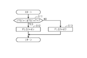
次に、図2を参照し、操舵が行われているか否かを判定すべく操舵判定部71が実行する処理ルーチンについて説明する。本処理ルーチンは、旋回支援制御が実施されている場合、所定の制御サイクル毎に繰り返し実行される。
本処理ルーチンにおいて、ステップS11では、操舵トルクTQInの絶対値が判定操舵トルクTQInTh以上であるか否かの判定が行われる。判定操舵トルクTQInThは、ステアリングホイール21を回転させる意志を運転者が有しているか否かの判断基準である。操舵トルクの絶対値|TQIn|が判定操舵トルクTQInTh以上である場合、操舵が行われている。
操舵トルクの絶対値|TQIn|が判定操舵トルクTQInTh以上である場合(S11:YES)、処理が次のステップS12に移行される。ステップS12において、操舵オーバーライドフラグFLG1にオンがセットされる。操舵オーバーライドフラグFLG1は、旋回支援制御の実施中に操舵が行われているときにはオンがセットされる一方で、旋回支援制御の実施中に操舵が行われていないときにはオフがセットされるフラグである。そして、本処理ルーチンが一旦終了される。一方、ステップS11において、操舵トルクの絶対値|TQIn|が判定操舵トルクTQInTh未満である場合(NO)、処理が次のステップS13に移行される。ステップS13において、操舵オーバーライドフラグFLG1にオフがセットされる。その後、本処理ルーチンが一旦終了される。
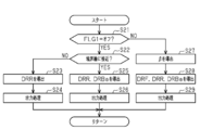
次に、図3を参照し、旋回支援制御を実施すべく旋回制御部72が実行する処理ルーチンについて説明する。本処理ルーチンは、旋回支援制御の実施条件が成立している場合には所定の制御サイクル毎に繰り返し実行される。実施条件とは、走行経路TRが設定されており、当該走行経路TRに従った車両制御の実施が許可されていることを含む。
本処理ルーチンにおいて、ステップS21では、操舵オーバーライドフラグFLG1にオフがセットされているか否かの判定が行われる。操舵オーバーライドフラグFLG1にオフがセットされている場合(S21:YES)、操舵が行われているとの判定がなされていないため、ステップS22~S26を含む非操舵時旋回支援制御が実施される。すなわち、非操舵時旋回支援制御において、ステップS22では、車両が走行レーンの境界線に接近しているか否かの判定が行われる。境界線は、走行レーンの側端に位置する線である。車両が境界線に接近しているか否かの判定は、車両前方を撮像する撮像装置によって得られた画像を解析することによって判定することができる。車両が境界線に接近している場合、車両の走行レーンからの逸脱が懸念される。
車両が境界線に接近しているとの判定がなされていない場合(S22:NO)、処理が次のステップS23に移行される。ステップS23において、目標旋回状態量導出部76によって導出された目標旋回状態量TSQTrと旋回状態量TSQとの偏差を基に、後輪舵角調整装置30の制御量DRRが導出される。続いて、ステップS24において、制御量を各制御部に出力する出力処理が実行される。この場合の出力処理では、ステップS23で導出された制御量DRRが後輪転舵制御部36に出力される。また、制動装置40の制御量DRBaとして「0(零)」が制動制御部46に出力され、且つ、前輪舵角調整装置10の制御量DRFとして「0(零)」が前輪転舵制御部16に出力される。そして、本処理ルーチンが一旦終了される。
この場合、後輪舵角調整装置30では、入力された制御量DRRを基に後輪用転舵アクチュエータ31が制御される。そのため、後輪転舵角θRが制御量DRRに応じた転舵角となる。一方、制動装置40に入力された制御量DRBaが「0(零)」であるため、制動装置40は右前輪FRと左前輪FLとの間に制動力差を発生させない。また、前輪舵角調整装置10に入力された制御量DRFが「0(零)」であるため、前輪舵角調整装置10は前輪転舵角θFを「0(零)」で維持する。すなわち、後輪舵角調整装置30が駆動される一方で、前輪舵角調整装置10及び制動制御部46が駆動されない。
一方、ステップS22において、車両が走行レーンの境界線に接近しているとの判定がなされている場合(YES)、処理が次のステップS25に移行される。ステップS25において、目標旋回状態量導出部76によって導出された目標旋回状態量TSQTrと旋回状態量TSQとの偏差を基に、後輪舵角調整装置30の制御量DRR及び制動装置40の制御量DRBaが導出される。
ここで、旋回支援制御の開始初期では車両が境界線に接近しているとの判定がなされていなかったにも拘わらず、車両が境界線に接近しているとの判定がなされるようになった場合を例として説明する。この場合、車両が境界線に接近しているとの判定がなされていない場合、後輪舵角調整装置30の制御量DRRとして目標旋回状態量TSQTrと旋回状態量TSQとの偏差に応じた値が設定されている。そして、車両が境界線に接近しているとの判定がなされていない状態から当該判定がなされている状態に移行すると、後輪舵角調整装置30の制御量DRRは移行前の値で保持される。一方、目標旋回状態量TSQTrと旋回状態量TSQとの偏差を基に、制動装置40の制御量DRBaとして導出される。これにより、制動装置40の制御量DRBaとして、車両の横方向の中心と走行レーンの横方向の中心とのずれを是正できる値が設定される。
そして、各制御量DRR,DRBaが導出されると、処理が次のステップS26に移行される。ステップS26において、制御量を各制御部に出力する出力処理が実行される。この場合の出力処理では、ステップS25で導出された制御量DRRが後輪転舵制御部36に出力され、且つ、制御量DRBaが制動制御部46に出力される。また、前輪舵角調整装置10の制御量DRFとして「0(零)」が前輪転舵制御部16に出力される。そして、本処理ルーチンが一旦終了される。
この場合、後輪舵角調整装置30では、入力された制御量DRRを基に後輪用転舵アクチュエータ31が制御される。そのため、後輪転舵角θRが制御量DRRに応じた転舵角となる。また、制動装置40では、入力された制御量DRBaを基に制動アクチュエータ41が制御される。そのため、右前輪FRと左前輪FLとの間に、制御量DRBaに応じた制動力差が発生する。一方、前輪舵角調整装置10に入力された制御量DRFが「0(零)」であるため、前輪舵角調整装置10は前輪転舵角θFを「0(零)」で維持する。すなわち、後輪舵角調整装置30及び制動装置40が駆動される一方で、前輪舵角調整装置10が駆動されない。
その一方で、ステップS21において、操舵オーバーライドフラグFLG1にオンがセットされている場合(NO)、操舵が行われているとの判定がなされているため、ステップS27~S29を含む操舵時旋回支援制御が実施される。すなわち、操舵時旋回支援制御において、ステップS27では、車体スリップ角βが導出される。車体スリップ角βは、例えば、前輪転舵角θF及び後輪転舵角θRを基に導出することができる。つまり、前輪転舵角θF及び後輪転舵角θRを調整することにより、車体スリップ角βを制御することができる。
次のステップS28において、目標旋回状態量導出部76によって導出された目標旋回状態量TSQTrと、目標車体スリップ角βTrと車体スリップ角βとの偏差と、操舵角Strとを基に、前輪舵角調整装置10の制御量DRF、後輪舵角調整装置30の制御量DRR及び制動装置40の制御量DRBaが導出される。
例えば、前輪舵角調整装置10の制御量DRFとして操舵角Strに応じた値が設定される。また、後輪舵角調整装置30の制御量DRRとして、目標車体スリップ角βTrと車体スリップ角βとの偏差に応じた値が設定される。制御量DRF,DRRに基づいて前輪舵角調整装置10及び後輪舵角調整装置30が制御された場合における旋回状態量の予測値と、目標旋回状態量TSQTrとの偏差に応じた値が、制動装置40の制御量DRBaとして導出される。そのため、旋回状態量の予測値と目標旋回状態量TSQTrとの偏差が「0(零)」である場合、制御量DRBaとして「0(零)」が設定されることもあり得る。
そして、ステップS29において、制御量を各制御部に出力する出力処理が実行される。この場合の出力処理では、ステップS28で導出された制御量DRFが前輪転舵制御部16に出力され、制御量DRRが後輪転舵制御部36に出力され、制御量DRBaが制動制御部46に出力される。そして、本処理ルーチンが一旦終了される。
この場合、前輪舵角調整装置10では、入力された制御量DRFを基に前輪用転舵アクチュエータ11が制御される。そのため、前輪転舵角θFが制御量DRFに応じた転舵角となる。また、後輪舵角調整装置30では、入力された制御量DRRを基に後輪用転舵アクチュエータ31が制御される。そのため、後輪転舵角θRが制御量DRRに応じた転舵角となる。また、制動装置40では、入力された制御量DRBaを基に制動アクチュエータ41が制御される。そのため、右前輪FRと左前輪FLとの間に、制御量DRBaに応じた制動力差が発生する。これにより、前輪舵角調整装置10、後輪舵角調整装置30及び制動装置40の駆動によって、目標旋回状態量TSQTrに旋回状態量TSQを追随させるとともに、目標車体スリップ角βTrに車体スリップ角βを追随させることができる。
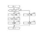
次に、図4を参照し、操舵装置20を制御するべく操舵指示部73が実行する処理ルーチンについて説明する。本処理ルーチンは、旋回支援制御が実施されているときに所定の制御サイクル毎に実行される。
本処理ルーチンにおいて、ステップS41では、操舵オーバーライドフラグFLG1にオフがセットされているか否かの判定が行われる。操舵オーバーライドフラグFLG1にオフがセットされている場合(S41:YES)、操舵が行われているとの判定がなされていないため、処理が次のステップS42に移行される。ステップS42において、車両の車体速度VS及びヨーレートYrなどを基に、セルフアライニングトルクTQsatが導出される。
続いて、ステップS42において、反力抑制トルクTQSとしてセルフアライニングトルクTQsatが設定される。次のステップS43において、ステップS42で導出した反力抑制トルクTQSをステアリングホイール21に付与する旨を操舵制御部26に出力する出力処理が実行される。本実施形態では、ステップS42で導出された反力抑制トルクTQSが、操舵角Strを中立点StrCで保持するトルクである保持トルクに相当する。すなわち、反力抑制トルクTQSを導出し、当該反力抑制トルクTQSを操舵制御部26に出力することが、操舵角Strを中立点StrCで維持する旨を操舵装置20に指示することに相当する。その後、本処理ルーチンが一旦終了される。
この場合、操舵装置20では、入力された反力抑制トルクTQSがステアリングホイール21に付与されるように操舵アクチュエータ22が制御される。そのため、操舵角Strが中立点StrCで維持される。
その一方で、ステップS41において、操舵オーバーライドフラグFLG1にオンがセットされている場合(NO)、操舵が行われているとの判定がなされているため、処理が次のステップS45に移行される。ステップS45において、運転者の操舵をアシストするトルクであるアシストトルクTQAsが導出される。すなわち、ステアリングホイール21に入力される操舵トルクTQInに応じた値がアシストトルクTQAsとして設定される。アシストトルクTQAsの絶対値は、操舵トルクTQInの絶対値が大きいほど大きくなる。次のステップS46において、ステップS45で導出したアシストトルクTQAsをステアリングホイール21に付与する旨を操舵制御部26に出力する出力処理が実行される。すなわち、アシストトルクTQAsを導出し、当該アシストトルクTQAsを操舵制御部26に出力することが、運転者の操舵をアシストする旨を操舵装置20に指示することに相当する。その後、本処理ルーチンが一旦終了される。
この場合、操舵装置20では、入力されたアシストトルクTQAsがステアリングホイール21に付与されるように操舵アクチュエータ22が制御される。これにより、運転者の操舵をアシストすることができる。
次に、本実施形態の作用及び効果について説明する。
旋回支援制御の実施中において操舵が行われていないときには、前輪転舵角θFが「0(零)」で維持される。そのため、保持トルクに相当する反力抑制トルクTQSを導出する場合、車体スリップ角βに応じたトルク成分の導出は必要であるものの、前輪転舵角θFに応じたトルク成分の導出は不要となる。したがって、前輪転舵角θFに応じたトルク成分を導出しなくてもよい分、走行制御装置70の演算負荷の増大を抑制しつつ、操舵角Strを中立点StrCで保持することができる。
旋回支援制御の実施中において操舵が行われていないときには、前輪転舵角θFが「0(零)」で維持される。そのため、保持トルクに相当する反力抑制トルクTQSを導出する場合、車体スリップ角βに応じたトルク成分の導出は必要であるものの、前輪転舵角θFに応じたトルク成分の導出は不要となる。したがって、前輪転舵角θFに応じたトルク成分を導出しなくてもよい分、走行制御装置70の演算負荷の増大を抑制しつつ、操舵角Strを中立点StrCで保持することができる。
また、旋回支援制御の実施中において操舵が行われていない場合、後輪舵角調整装置30の駆動だけでは車両が走行レーンから逸脱する可能性が生じたときには、制動装置40も駆動されるようになる。このように後輪舵角調整装置30に加えて制動装置40をも駆動させることにより、走行レーンに従った車両の自動走行を支援する際における制御性を高めることができる。
旋回支援制御の実施中において操舵が行われるようになると、前輪舵角調整装置10の駆動によって、操舵角Strの変化に応じて前輪転舵角θFが調整されるようになる。これにより、操舵が行われるようになっても前輪転舵角θFが「0(零)」で維持される場合とは異なり、操舵アクチュエータ22からステアリングホイール21に付与するトルクの大きさの算出が複雑化しにくくなる。
また、旋回支援制御の実施中において操舵が行われている場合には、前輪転舵角θF及び後輪転舵角θRがそれぞれ調整される。そのため、旋回状態量TSQに加えて車体スリップ角βをも制御することができる。これにより、車両旋回時における車両の旋回挙動の制御性を高めることができる。
旋回支援制御の実施中において操舵が行われる場合、目標旋回状態量TSQTrとして、操舵の開始前の値と、操舵角Strに応じた値との和を設定する場合を考える。この場合、操舵が開始されると、目標旋回状態量TSQTrが一気に大きくなって車両のヨーモーメントの大きさが急に大きくなるおそれがある。そして、車両のヨーモーメントの大きさの急激な変化に対する不快感を車両の運転者に与えてしまうおそれがある。
これに対し、本実施形態では、旋回支援制御の実施中において操舵が行われている場合、要求旋回状態量TSQRと目標自動旋回状態量TSQATrとのうち、絶対値が大きくなる方のパラメータを基に、目標旋回状態量TSQTrが導出される。これにより、操舵の開始時に目標旋回状態量TSQTrが急に大きくなることを抑制できる。すなわち、操舵の開始によって車両のヨーモーメントの大きさが急に大きくなることを抑制できる。その結果、操舵の開始時における車両の旋回挙動に対する不快感を運転者に与えにくくなる。
上記実施形態は、以下のように変更して実施することができる。上記実施形態及び以下の変更例は、技術的に矛盾しない範囲で互いに組み合わせて実施することができる。
・操舵時旋回支援制御の実施時にあっては、要求旋回状態量TSQRと目標自動旋回状態量TSQATrとのうち、絶対値が大きい方のパラメータを基に目標旋回状態量TSQTrを導出するのであれば、目標旋回状態量TSQTrを当該大きい方のパラメータとは異なる値としてもよい。例えば、当該大きい方のパラメータに所定のオフセット値を加算した値を目標旋回状態量TSQTrとして導出するようにしてもよい。
・操舵時旋回支援制御の実施時にあっては、要求旋回状態量TSQRと目標自動旋回状態量TSQATrとのうち、絶対値が大きい方のパラメータを基に目標旋回状態量TSQTrを導出するのであれば、目標旋回状態量TSQTrを当該大きい方のパラメータとは異なる値としてもよい。例えば、当該大きい方のパラメータに所定のオフセット値を加算した値を目標旋回状態量TSQTrとして導出するようにしてもよい。
・操舵時旋回支援制御の実施時にあっては、操舵の開始前の目標旋回状態量と、操舵角Strに応じた値との和を目標旋回状態量TSQTrとして設定するようにしてもよい。
・旋回支援制御の実施によって制動装置40を駆動させる場合、右後輪RRと左後輪RLとの間に制動力差を発生させることにより、車両にヨーモーメントを発生させるようにしてもよい。
・旋回支援制御の実施によって制動装置40を駆動させる場合、右後輪RRと左後輪RLとの間に制動力差を発生させることにより、車両にヨーモーメントを発生させるようにしてもよい。
・非旋回時支援制御の実施時には、制動装置40を駆動させず、後輪舵角調整装置30を駆動させるようにしてもよい。この場合、操舵が行われているとの判定がなされるようになった場合、すなわち旋回時支援制御の実施時には、前輪舵角調整装置10及び後輪舵角調整装置30を駆動させる一方で、制動装置40を駆動させないようにしてもよい。
・非旋回時支援制御の実施時には、後輪舵角調整装置30を駆動させず、制動装置40を駆動させるようにしてもよい。この場合、操舵が行われているとの判定がなされるようになった場合、すなわち非旋回時支援制御の実施時には、前輪舵角調整装置10及び制動装置40を駆動させる一方で、後輪舵角調整装置30を駆動させないようにしてもよい。この場合、後輪舵角調整装置30を備えない車両に、上記走行制御装置を適用することができる。
・車両として、右輪専用の駆動モータと、左輪専用の駆動モータとを備える車両がある。この場合、右輪専用の駆動モータの駆動と左輪専用の駆動モータの駆動によって、右輪に入力される駆動トルクと、左輪に入力される駆動トルクとの間に差分を発生させ、当該差分に応じたヨーモーメントを車両に発生させることができる。そのため、こうした車両に走行制御装置70を適用する場合、各駆動モータと各駆動モータを制御する制御部とを有する駆動装置を、旋回制御装置として機能させるようにしてもよい。
次に、上記実施形態及び変更例から把握できる技術的思想について記載する。
(イ)前記旋回制御部は、操舵が行われている場合の前記旋回支援制御では、前記目標旋回状態量と前記旋回状態量との偏差、及び、車両の車体スリップ角の目標である目標スリップ角と車体スリップ角との偏差を基に、前記前輪舵角調整装置の制御量、及び、前記後輪舵角調整装置の制御量を導出し、前記前輪舵角調整装置の制御量を当該前輪舵角調整装置に出力し、前記後輪舵角調整装置の制御量を当該後輪舵角調整装置に出力することが好ましい。
(イ)前記旋回制御部は、操舵が行われている場合の前記旋回支援制御では、前記目標旋回状態量と前記旋回状態量との偏差、及び、車両の車体スリップ角の目標である目標スリップ角と車体スリップ角との偏差を基に、前記前輪舵角調整装置の制御量、及び、前記後輪舵角調整装置の制御量を導出し、前記前輪舵角調整装置の制御量を当該前輪舵角調整装置に出力し、前記後輪舵角調整装置の制御量を当該後輪舵角調整装置に出力することが好ましい。
Claims (4)
- 前輪の転舵角の調整を通じ、車両の旋回に関する状態量である旋回状態量を制御する前輪舵角調整装置と、前記前輪舵角調整装置とは別に設けられ、前記旋回状態量を制御する旋回制御装置と、操舵トルクが入力されるステアリングホイールを有するとともに、前記前輪に連結されている操舵装置と、を備える車両に適用され、
前記前輪舵角調整装置及び前記旋回制御装置のうちの少なくとも一方の装置を駆動させることによって、前記旋回状態量の目標である目標旋回状態量に前記旋回状態量を追随させる旋回支援制御を実施する旋回制御部と、
前記旋回支援制御の実施中で操舵が行われていないときには、前記ステアリングホイールの操舵角を中立点で保持するトルクである保持トルクを導出し、同保持トルクの前記ステアリングホイールへの付与を前記操舵装置に指示する操舵指示部と、を備え、
前記旋回制御部は、操舵が行われていない場合の前記旋回支援制御では、前記旋回制御装置を駆動させる一方で前記前輪舵角調整装置を駆動させず、操舵が行われている場合の前記旋回支援制御では、前記前輪舵角調整装置を駆動させる
車両の走行制御装置。 - 前記車両は、前記旋回制御装置として、当該車両の後輪の転舵角の調整を通じて前記旋回状態量を調整する後輪舵角調整装置を備えるものであり、
前記旋回制御部は、操舵が行われている場合の前記旋回支援制御では、前記前輪舵角調整装置及び前記後輪舵角調整装置を駆動させる
請求項1に記載の車両の走行制御装置。 - 前記車両には、前記旋回制御装置として、前記車両の右輪と左輪との間の制動力差を調整することで前記旋回状態量を制御する制動装置を備えるものであり、
前記旋回制御部は、操舵が行われていない場合の前記旋回支援制御では、前記後輪舵角調整装置及び前記制動装置のうちの少なくとも一方の装置を駆動させ、且つ、前記前輪舵角調整装置を駆動させない
請求項2に記載の車両の走行制御装置。 - 操舵に関する操舵関連値を取得し、前記旋回状態量の要求値である要求旋回状態量として当該操舵関連値に応じた値を設定する要求旋回状態量設定部と、
設定されている走行経路に従って前記車両を自動旋回させるための前記旋回状態量の目標である目標自動旋回状態量を設定する目標自動旋回状態量設定部と、
前記要求旋回状態量及び前記目標自動旋回状態量のうち、絶対値が大きくなる方の状態量を基に前記目標旋回状態量を導出する目標旋回状態量導出部と、を備える
請求項1~請求項3のうち何れか一項に記載の車両の走行制御装置。
Priority Applications (3)
| Application Number | Priority Date | Filing Date | Title |
|---|---|---|---|
| US17/436,842 US12017712B2 (en) | 2019-03-25 | 2020-03-03 | Travel control device for vehicle |
| DE112020001470.3T DE112020001470T5 (de) | 2019-03-25 | 2020-03-03 | Fahrsteuerungsvorrichtung für ein Fahrzeug |
| CN202080023605.6A CN113613984B (zh) | 2019-03-25 | 2020-03-03 | 车辆的行驶控制装置 |
Applications Claiming Priority (2)
| Application Number | Priority Date | Filing Date | Title |
|---|---|---|---|
| JP2019-056649 | 2019-03-25 | ||
| JP2019056649A JP7192605B2 (ja) | 2019-03-25 | 2019-03-25 | 車両の走行制御装置 |
Publications (1)
| Publication Number | Publication Date |
|---|---|
| WO2020195604A1 true WO2020195604A1 (ja) | 2020-10-01 |
Family
ID=72609932
Family Applications (1)
| Application Number | Title | Priority Date | Filing Date |
|---|---|---|---|
| PCT/JP2020/008884 Ceased WO2020195604A1 (ja) | 2019-03-25 | 2020-03-03 | 車両の走行制御装置 |
Country Status (5)
| Country | Link |
|---|---|
| US (1) | US12017712B2 (ja) |
| JP (1) | JP7192605B2 (ja) |
| CN (1) | CN113613984B (ja) |
| DE (1) | DE112020001470T5 (ja) |
| WO (1) | WO2020195604A1 (ja) |
Families Citing this family (1)
| Publication number | Priority date | Publication date | Assignee | Title |
|---|---|---|---|---|
| JP7259574B2 (ja) * | 2019-06-17 | 2023-04-18 | 株式会社ジェイテクト | 制御装置、および転舵装置 |
Citations (3)
| Publication number | Priority date | Publication date | Assignee | Title |
|---|---|---|---|---|
| JP2006282168A (ja) * | 2006-04-03 | 2006-10-19 | Nissan Motor Co Ltd | 車線逸脱防止装置 |
| JP2012006506A (ja) * | 2010-06-25 | 2012-01-12 | Toyota Motor Corp | 車両の制御装置 |
| JP2012232676A (ja) * | 2011-05-02 | 2012-11-29 | Toyota Motor Corp | 車両の挙動制御装置 |
Family Cites Families (22)
| Publication number | Priority date | Publication date | Assignee | Title |
|---|---|---|---|---|
| EP0499027A3 (en) * | 1991-01-10 | 1993-03-17 | Nsk Ltd | Four-wheel steering apparatus |
| JP2768034B2 (ja) * | 1991-03-28 | 1998-06-25 | 日産自動車株式会社 | 車両用舵角制御装置 |
| JP3687252B2 (ja) * | 1997-02-28 | 2005-08-24 | 日産自動車株式会社 | 自動車の操舵装置 |
| JP4867313B2 (ja) * | 2004-12-27 | 2012-02-01 | 日産自動車株式会社 | 車線逸脱防止装置 |
| JP2010064721A (ja) * | 2008-09-12 | 2010-03-25 | Advics Co Ltd | 車両の運動制御装置 |
| CN102612456B (zh) * | 2010-04-14 | 2014-12-31 | 丰田自动车株式会社 | 车辆的控制装置 |
| JP5234061B2 (ja) * | 2010-07-30 | 2013-07-10 | 日産自動車株式会社 | 車両用操舵装置 |
| CN103237707B (zh) * | 2010-12-01 | 2015-05-06 | 丰田自动车株式会社 | 车辆的运动控制装置 |
| JP5691459B2 (ja) * | 2010-12-06 | 2015-04-01 | トヨタ自動車株式会社 | 車両の挙動制御装置 |
| US9707996B2 (en) * | 2011-08-31 | 2017-07-18 | Toyota Jidosha Kabushiki Kaisha | Vehicle drive-control device |
| CN104487268B (zh) * | 2012-07-20 | 2016-04-20 | 日产自动车株式会社 | 车辆用悬架装置、使用该装置的汽车以及转向控制方法 |
| JP5620951B2 (ja) * | 2012-07-27 | 2014-11-05 | 富士重工業株式会社 | 車両のパワーステアリング制御装置 |
| JP5668746B2 (ja) * | 2012-12-26 | 2015-02-12 | トヨタ自動車株式会社 | 車両の制御装置 |
| JP6194647B2 (ja) * | 2013-06-07 | 2017-09-13 | 株式会社デンソー | ステアリング制御装置 |
| JP2015182516A (ja) * | 2014-03-20 | 2015-10-22 | トヨタ自動車株式会社 | 車両挙動制御装置 |
| CN107531276B (zh) * | 2015-04-09 | 2018-12-14 | 日产自动车株式会社 | 车道维持辅助装置 |
| US10124828B2 (en) * | 2016-06-15 | 2018-11-13 | GM Global Technology Operations LLC | Autonomous vehicle steering control methods and systems |
| JP6753199B2 (ja) * | 2016-08-02 | 2020-09-09 | いすゞ自動車株式会社 | 車線維持支援装置及び車線維持支援方法 |
| JP6799778B2 (ja) * | 2016-10-06 | 2020-12-16 | 株式会社ジェイテクト | 車両用操舵装置 |
| JP6489135B2 (ja) * | 2017-01-13 | 2019-03-27 | トヨタ自動車株式会社 | 車両の運転支援装置 |
| DE102017209231B4 (de) * | 2017-05-31 | 2021-02-25 | Zf Friedrichshafen Ag | Verfahren und Anordnung zur Plausibilisierung und/oder (Re-) Initialisierung einer Hinterradlenkung |
| CN112218792B (zh) * | 2018-06-01 | 2024-01-09 | 捷豹路虎有限公司 | 用于控制转向的设备和方法 |
-
2019
- 2019-03-25 JP JP2019056649A patent/JP7192605B2/ja active Active
-
2020
- 2020-03-03 US US17/436,842 patent/US12017712B2/en active Active
- 2020-03-03 CN CN202080023605.6A patent/CN113613984B/zh active Active
- 2020-03-03 DE DE112020001470.3T patent/DE112020001470T5/de active Granted
- 2020-03-03 WO PCT/JP2020/008884 patent/WO2020195604A1/ja not_active Ceased
Patent Citations (3)
| Publication number | Priority date | Publication date | Assignee | Title |
|---|---|---|---|---|
| JP2006282168A (ja) * | 2006-04-03 | 2006-10-19 | Nissan Motor Co Ltd | 車線逸脱防止装置 |
| JP2012006506A (ja) * | 2010-06-25 | 2012-01-12 | Toyota Motor Corp | 車両の制御装置 |
| JP2012232676A (ja) * | 2011-05-02 | 2012-11-29 | Toyota Motor Corp | 車両の挙動制御装置 |
Also Published As
| Publication number | Publication date |
|---|---|
| DE112020001470T5 (de) | 2021-12-23 |
| JP7192605B2 (ja) | 2022-12-20 |
| US12017712B2 (en) | 2024-06-25 |
| JP2020157811A (ja) | 2020-10-01 |
| CN113613984B (zh) | 2023-04-04 |
| CN113613984A (zh) | 2021-11-05 |
| US20220177030A1 (en) | 2022-06-09 |
Similar Documents
| Publication | Publication Date | Title |
|---|---|---|
| CN104955713B (zh) | 用于稳定包括牵引车和拖挂车的牵引车组的方法和装置 | |
| EP1800995B1 (en) | Controller of electric power steering device of vehicle having wheel slip controller acting on steered wheel | |
| EP2017161A2 (en) | Vehicle steering apparatus | |
| US10518808B2 (en) | Method for influencing the direction of travel of motor vehicles | |
| JP2018525263A (ja) | 車両を操舵する方法、自動車用のコントローラおよび自動車 | |
| JP4997478B2 (ja) | 車両用操舵装置 | |
| JP2021011190A (ja) | 車両の操舵支援装置 | |
| KR20180003655A (ko) | 차량용 자세 제어방법 | |
| JP2013039892A (ja) | 車両のヨーモーメント発生旋回効率化装置 | |
| KR20160045322A (ko) | 후륜 조향장치 및 그 제어방법 | |
| JP5347499B2 (ja) | 車両制御装置及び車両制御方法 | |
| JP6036522B2 (ja) | 電動ステアリング制御装置 | |
| JP7192605B2 (ja) | 車両の走行制御装置 | |
| JP6634872B2 (ja) | 車両用制御装置 | |
| JP5889757B2 (ja) | 車両制御装置 | |
| JP4449661B2 (ja) | 車両用操舵装置 | |
| JP5012314B2 (ja) | 車両用操舵装置 | |
| JP4254710B2 (ja) | 車輌用操舵制御装置 | |
| JP2009067118A (ja) | 車両操舵装置 | |
| JP2002370658A (ja) | 操舵反力制御装置 | |
| CN112449624A (zh) | 操舵控制装置以及操舵控制方法 | |
| JP5685164B2 (ja) | 車両の制動制御装置 | |
| CN106564530B (zh) | 在行驶动态边界条件下辅助机动车辆驾驶员的方法和装置 | |
| JP4881631B2 (ja) | 車両操舵装置 | |
| JPH08156816A (ja) | 車両のヨーイング運動量制御装置 |
Legal Events
| Date | Code | Title | Description |
|---|---|---|---|
| 121 | Ep: the epo has been informed by wipo that ep was designated in this application |
Ref document number: 20776410 Country of ref document: EP Kind code of ref document: A1 |
|
| 122 | Ep: pct application non-entry in european phase |
Ref document number: 20776410 Country of ref document: EP Kind code of ref document: A1 |