WO2020195449A1 - 電子写真機器用現像ロールおよび電子写真機器用現像ロールの製造方法 - Google Patents
電子写真機器用現像ロールおよび電子写真機器用現像ロールの製造方法 Download PDFInfo
- Publication number
- WO2020195449A1 WO2020195449A1 PCT/JP2020/007322 JP2020007322W WO2020195449A1 WO 2020195449 A1 WO2020195449 A1 WO 2020195449A1 JP 2020007322 W JP2020007322 W JP 2020007322W WO 2020195449 A1 WO2020195449 A1 WO 2020195449A1
- Authority
- WO
- WIPO (PCT)
- Prior art keywords
- convex portion
- developing roll
- large convex
- layer
- convex portions
- Prior art date
- Legal status (The legal status is an assumption and is not a legal conclusion. Google has not performed a legal analysis and makes no representation as to the accuracy of the status listed.)
- Ceased
Links
Images

Classifications
-
- G—PHYSICS
- G03—PHOTOGRAPHY; CINEMATOGRAPHY; ANALOGOUS TECHNIQUES USING WAVES OTHER THAN OPTICAL WAVES; ELECTROGRAPHY; HOLOGRAPHY
- G03G—ELECTROGRAPHY; ELECTROPHOTOGRAPHY; MAGNETOGRAPHY
- G03G15/00—Apparatus for electrographic processes using a charge pattern
- G03G15/06—Apparatus for electrographic processes using a charge pattern for developing
- G03G15/08—Apparatus for electrographic processes using a charge pattern for developing using a solid developer, e.g. powder developer
- G03G15/0806—Apparatus for electrographic processes using a charge pattern for developing using a solid developer, e.g. powder developer on a donor element, e.g. belt, roller
- G03G15/0818—Apparatus for electrographic processes using a charge pattern for developing using a solid developer, e.g. powder developer on a donor element, e.g. belt, roller characterised by the structure of the donor member, e.g. surface properties
-
- F—MECHANICAL ENGINEERING; LIGHTING; HEATING; WEAPONS; BLASTING
- F16—ENGINEERING ELEMENTS AND UNITS; GENERAL MEASURES FOR PRODUCING AND MAINTAINING EFFECTIVE FUNCTIONING OF MACHINES OR INSTALLATIONS; THERMAL INSULATION IN GENERAL
- F16C—SHAFTS; FLEXIBLE SHAFTS; ELEMENTS OR CRANKSHAFT MECHANISMS; ROTARY BODIES OTHER THAN GEARING ELEMENTS; BEARINGS
- F16C13/00—Rolls, drums, discs, or the like; Bearings or mountings therefor
-
- G—PHYSICS
- G03—PHOTOGRAPHY; CINEMATOGRAPHY; ANALOGOUS TECHNIQUES USING WAVES OTHER THAN OPTICAL WAVES; ELECTROGRAPHY; HOLOGRAPHY
- G03G—ELECTROGRAPHY; ELECTROPHOTOGRAPHY; MAGNETOGRAPHY
- G03G15/00—Apparatus for electrographic processes using a charge pattern
- G03G15/06—Apparatus for electrographic processes using a charge pattern for developing
- G03G15/08—Apparatus for electrographic processes using a charge pattern for developing using a solid developer, e.g. powder developer
- G03G15/0806—Apparatus for electrographic processes using a charge pattern for developing using a solid developer, e.g. powder developer on a donor element, e.g. belt, roller
-
- G—PHYSICS
- G03—PHOTOGRAPHY; CINEMATOGRAPHY; ANALOGOUS TECHNIQUES USING WAVES OTHER THAN OPTICAL WAVES; ELECTROGRAPHY; HOLOGRAPHY
- G03G—ELECTROGRAPHY; ELECTROPHOTOGRAPHY; MAGNETOGRAPHY
- G03G15/00—Apparatus for electrographic processes using a charge pattern
- G03G15/06—Apparatus for electrographic processes using a charge pattern for developing
- G03G15/08—Apparatus for electrographic processes using a charge pattern for developing using a solid developer, e.g. powder developer
- G03G15/0806—Apparatus for electrographic processes using a charge pattern for developing using a solid developer, e.g. powder developer on a donor element, e.g. belt, roller
- G03G15/0808—Apparatus for electrographic processes using a charge pattern for developing using a solid developer, e.g. powder developer on a donor element, e.g. belt, roller characterised by the developer supplying means, e.g. structure of developer supply roller
-
- G—PHYSICS
- G03—PHOTOGRAPHY; CINEMATOGRAPHY; ANALOGOUS TECHNIQUES USING WAVES OTHER THAN OPTICAL WAVES; ELECTROGRAPHY; HOLOGRAPHY
- G03G—ELECTROGRAPHY; ELECTROPHOTOGRAPHY; MAGNETOGRAPHY
- G03G2215/00—Apparatus for electrophotographic processes
- G03G2215/08—Details of powder developing device not concerning the development directly
- G03G2215/0855—Materials and manufacturing of the developing device
- G03G2215/0858—Donor member
-
- G—PHYSICS
- G03—PHOTOGRAPHY; CINEMATOGRAPHY; ANALOGOUS TECHNIQUES USING WAVES OTHER THAN OPTICAL WAVES; ELECTROGRAPHY; HOLOGRAPHY
- G03G—ELECTROGRAPHY; ELECTROPHOTOGRAPHY; MAGNETOGRAPHY
- G03G2215/00—Apparatus for electrophotographic processes
- G03G2215/08—Details of powder developing device not concerning the development directly
- G03G2215/0855—Materials and manufacturing of the developing device
- G03G2215/0858—Donor member
- G03G2215/0861—Particular composition or materials
Definitions
- the present invention relates to a developing roll for electrophotographic equipment and a method for manufacturing a developing roll for electrophotographic equipment, which is suitably used in electrophotographic equipment such as copiers, printers, and facsimiles that employ an electrophotographic method.
- the developing roll has the role of transporting the amount of toner required for printing to the photoconductor.
- Roughness is provided on the surface of the developing roll in order to secure the amount of toner conveyed.
- roughness is imparted to the surface of the rubber elastic layer by polishing the surface of the rubber elastic layer of the developing roll.
- the surface layer containing alumina particles and resin is surface-treated by irradiation with ultraviolet rays or the like to form a plurality of convex portions containing alumina particles and resin on the surface of the surface layer, and alumina is formed in the convex portions.
- Roughness is imparted to the surface of the surface layer of the developing member by exposing a part of the particles.
- the contact area with the photoconductor or layer-forming blade becomes large, and toner is fused to the photoconductor or layer-forming blade by physical pressing (toner fill). Ming) occurs.
- a method of imparting roughness to the surface of the developing roll a method of blending particles forming the roughness into the surface layer, a method of transferring the roughness of the inner surface of the molding die to the surface of the rubber elastic layer, and a method of transferring the roughness of the rubber elastic layer. There is a method of polishing the surface.
- the convex portion where the particles are present is easily scraped, and the toner is easily fused from this point. Further, in either method, the toner is easily fused by depositing the toner in the concave portion between the convex portions.
- An object to be solved by the present invention is to provide a developing roll for electrophotographic equipment and a method for manufacturing a developing roll for electrophotographic equipment, which can suppress toner fusion and toner filming.
- the developing roll for an electrophotographic apparatus includes a shaft body and an elastic body layer formed on the outer periphery of the shaft body, and has a width of 3 on the surface of the elastic body layer.
- a plurality of large convex portions having a height of 3.0 to 12 ⁇ m and a height of 0 to 12 ⁇ m are formed, and a plurality of irregularities having a ten-point average roughness Rz of 2.0 to 4.0 ⁇ m are formed on the side surface of the large convex portions.
- the gist is to have a small convex portion.
- the large convex portion may be a linear convex portion continuous in the circumferential direction.
- the large convex portion may be a convex portion having a triangular cross section.
- the small convex portion may consist of wrinkles formed on the side surface of the large convex portion.
- a plurality of small convex portions forming unevenness of Rz 2.0 to 4.0 ⁇ m may be provided on the surface of the bottom portion of the groove between the large convex portion and the large convex portion.
- the distance between the large convex portion and the large convex portion is preferably 6.0 to 9.0 ⁇ m.
- the distance between the small convex portion and the small convex portion is preferably 1.0 to 5.0 ⁇ m.
- the surface area ratio S / S 0 of the elastic layer is preferably 5.0 to 8.0. It is preferable that the surface of the elastic body layer contains a compound having an isocyanuric acid skeleton.
- the elastic layer may contain a polymer having a carbon-carbon double bond.
- the method for manufacturing a developing roll for an electrophotographic apparatus includes a polymer having a carbon-carbon double bond on the outer periphery of a shaft body, and has a width of 3.0 to 12 ⁇ m and a height of 3.0 to 12 ⁇ m.
- the gist is to have a step of forming a plurality of small convex portions on the side surface of the convex portion to form irregularities having a ten-point average roughness Rz of 2.0 to 4.0 ⁇ m.
- the surface of the elastic layer has a plurality of large convex portions having a width of 3.0 to 12 ⁇ m and a height of 3.0 to 12 ⁇ m, and the side surfaces of the large convex portions.
- the ten-point average roughness Rz has a plurality of small convex portions forming irregularities of 2.0 to 4.0 ⁇ m, toner fusion and toner filming can be suppressed.
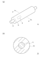
- FIG. 3A is a schematic external view (a) of a developing roll for an electrophotographic apparatus according to an embodiment of the present invention, and is a sectional view taken along line AA (b).
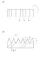
- FIG. 1 is an enlarged view showing a part B of the surface of the developing roll for electrophotographic equipment shown in FIG. 1, and is a plan view (a) and a cross-sectional view (b). It is the figure which showed the part C of the cross section shown in FIG. 2 (b) further enlarged.
- FIG. 1 is an overall view of a developing roll according to an embodiment and a cross-sectional view taken along the line AA.
- FIG. 2 is an enlarged view of a part B of the surface of the elastic layer, and FIG. It is an enlarged view of a part C of a part B.
- the X direction is the axial direction of the developing roll, and the Y direction is the circumferential direction of the developing roll.
- the developing roll 10 includes a shaft body 12 and an elastic body layer 14 formed on the outer periphery of the shaft body 12.
- the elastic layer 14 is a layer (base layer) that is a base of the developing roll 10.
- the elastic layer 14 is a layer (outermost layer) that appears on the radial surface of the developing roll 10.
- an intermediate layer such as a resistance adjusting layer may be arranged between the shaft body 12 and the elastic body layer 14, if necessary.
- the developing roll 10 has a plurality of large convex portions 16 having a width W of 3.0 to 12 ⁇ m and a height H of 3.0 to 12 ⁇ m on the surface of the elastic body layer 14.
- the plurality of large convex portions 16 are convex portions having a triangular cross section, and are linear convex portions (convex stripes) continuous in the circumferential direction (Y direction in FIG. 2A). ing.
- the developing roll 10 is excellent in toner transferability because it has the plurality of large convex portions 16 having the width and height described above on the surface of the elastic body layer 14.
- the distance D 1 between the large convex portion 16 and the large convex portion 16 is not particularly limited, but is preferably 6.0 to 9.0 ⁇ m. When the distance D 1 between the large convex portion 16 and the large convex portion 16 is within the above range, appropriate toner transferability can be ensured.
- the width W of the large convex portion 16 is more preferably 4.0 to 11.0 ⁇ m.
- the height H of the large convex portion 16 is more preferably 4.0 to 10.0 ⁇ m.
- the distance D 1 between the large convex portion 16 and the large convex portion 16 is more preferably 7.0 to 18.0 ⁇ m.
- the side surface of the large convex portion 16 has a plurality of small convex portions 18 forming irregularities having a ten-point average roughness Rz of 2.0 to 4.0 ⁇ m.
- the plurality of small convex portions 18 are formed of wrinkles formed on the side surface of the large convex portion 16. Since the developing roll 10 has a plurality of small convex portions 18 having the above-mentioned size on the side surface of the large convex portion 16, the toner that has entered between the large convex portions 16 adheres between the large convex portions 16 and is deposited as it is. Is suppressed, and toner fusion to the developing roll 10 is suppressed.
- the distance D 2 between the small convex portion 18 and the small convex portion 18 is not particularly limited, but is preferably 1.0 to 5.0 ⁇ m.
- the elastic body layer 14 having a plurality of large convex portions 16 and a plurality of small convex portions 18 can be produced as follows.
- a base layer containing a polymer having a carbon-carbon double bond on the outer periphery of the shaft body 12 and having a plurality of large convex portions 16 having a width of 3.0 to 12 ⁇ m and a height of 3.0 to 12 ⁇ m on the surface is formed.
- a plurality of small convex portions 18 are not yet formed on the side surface of the large convex portion 16 of the base layer.
- the base layer can be produced by molding a rubber composition for forming an elastic layer containing a polymer having a carbon-carbon double bond with a mold and then polishing the surface of the obtained rubber layer. ..
- the large convex portion 16 In order to make the large convex portion 16 a linear convex portion (convex) continuous in the circumferential direction, it may be polished along the circumferential direction. Further, for example, by using a wedge-shaped abrasive, the large convex portion 16 can be made into a convex portion having a triangular cross section.
- the large convex portion 16 of the base layer may be formed by imparting a predetermined roughness to the inner surface of the mold and transferring the roughness of the inner surface of the mold in mold molding.
- the surface of the base layer is impregnated with chlorinated isocyanuric acid, the surface of the base layer impregnated with chlorinated isocyanuric acid is cured, and the ten-point average roughness Rz is 2.0 to the side surface of the large convex portion 16.
- a plurality of small convex portions 18 forming an unevenness of 4.0 ⁇ m are formed.
- the impregnated region of the base layer expands. Then, when the surface of the base layer impregnated with chlorinated isocyanuric acid is cured, the impregnated region of the base layer shrinks. At this time, a shrinkage difference occurs between the surface and the inside, and the inside shrinks more than the surface. As a result, wrinkles are generated on the surface, and a plurality of wrinkled small convex portions 18 are formed on the side surface of the large convex portion 16.
- the generation of wrinkles due to such a shrinkage difference occurs by impregnating the base layer having a plurality of large convex portions 16 with chlorinated isocyanuric acid. Even if the rubber layer having no plurality of large convex portions 16 is impregnated with chlorinated isocyanuric acid, such wrinkles are not observed. Further, even if the base layer having the plurality of large convex portions 16 is impregnated with a compound other than chlorinated isocyanuric acid, for example, isocyanate, such wrinkles are not observed.
- the base layer can be impregnated with chlorinated isocyanuric acid using a surface treatment liquid containing chlorinated isocyanuric acid.
- chlorinated isocyanuric acid examples include monochloroisocyanuric acid, dichloroisocyanuric acid, trichloroisocyanuric acid, and salts thereof.
- the surface treatment liquid may contain a solvent for dissolving or dispersing chlorinated isocyanuric acid.
- the solvent to be dissolved include ethyl acetate, toluene, methyl ethyl ketone (MEK), acetone and the like.
- solvent to be dispersed examples include tert-butyl alcohol (TBA) and the like.
- the solvent one or two kinds of those to be dissolved and one kind of solvent to be dispersed may be used in combination.
- Toluene and methyl ethyl ketone are more preferable as the solvent to be dissolved, from the viewpoints of high polarity and easy formation of a plurality of wrinkled small protrusions 18.
- the magnitude of the ten-point average roughness Rz on the side surface of the large convex portion 16 can be adjusted by the amount of impregnation of chlorinated isocyanuric acid, the amount of solvent for diluting chlorinated isocyanuric acid, the solvent type, and the like. For example, when a highly polar solvent is used as the solvent to be dissolved, the impregnation depth becomes deep, the shrinkage difference between the surface and the inside becomes large, and the ten-point average roughness Rz tends to be large.
- the surface treatment liquid may contain a modifying component such as a silicone compound or a fluorine-containing compound that lowers the tackiness of the surface of the elastic layer 14.
- the silicone compound and the fluorine-containing compound are preferably bonded to the polymer component of the elastic layer 14 by a chemical bond.
- examples of such a silicone compound include a silicone compound having a carbon-carbon double bond and a fluorine-containing compound having a carbon-carbon double bond.
- dichloroisocyanuric acid or trichloroisocyanuric acid is used as the chlorinated isocyanuric acid. It may be used or a photopolymerization initiator may be used.
- silicone compound having a carbon-carbon double bond examples include an acrylic monomer having a silicone group.
- the acrylic monomer represents (meth) acrylate and (meth) acrylamide.
- (Meta) acrylate is a general term for acrylate and methacrylate.
- (Meta) acrylamide is a general term for acrylamide and metaacrylamide.
- silicone group examples include a dimethyl silicone group, a diethyl silicone group, and a diphenyl silicone group.
- silicone compound having a carbon-carbon double bond those having a number average molecular weight in the range of 200 to 30,000 can be preferably used.
- Examples of the fluorine-containing compound having a carbon-carbon double bond include an acrylic monomer having a fluorine-containing group.
- the acrylic monomer represents (meth) acrylate and (meth) acrylamide.
- (Meta) acrylate is a general term for acrylate and methacrylate.
- (Meta) acrylamide is a general term for acrylamide and metaacrylamide.
- fluorine-containing group examples include fluoroalkyl groups having 1 to 20 carbon atoms.
- the fluoroalkyl group may be a perfluoroalkyl group in which all hydrogen atoms of the alkyl group are substituted with fluorine atoms, or a fluoroalkyl group in which some hydrogen atoms of the alkyl group are substituted with fluorine atoms. You may.
- fluoroalkyl group having 1 to 20 carbon atoms examples include a trifluoromethyl group, a pentafluoroethyl group, a heptafluoropropyl group, a nonafluorobutyl group, a trifluoroethyl group, a pentafluoropropyl group and a heptafluorobutyl group. ..
- the photopolymerization initiator is not particularly limited as long as it initiates photopolymerization of the photopolymerizable compound, and for example, alkylphenones, acetophenones, benzoin ethers, benzophenones, thioxanthones, anthraquinones, benzyls, etc.
- photopolymerization initiators such as biacetyls. Specific examples thereof include benzyl dimethyl ketal, 2-hydroxy-2-methyl-1-phenyl-propane-1-one, methyl-O-benzoyl benzoate, 1-hydroxycyclohexylphenyl ketone and the like.
- the content of the photopolymerization initiator in the surface treatment liquid is in the range of 10 to 100 parts by mass with respect to 1 part by mass in total of the silicone compound having a carbon-carbon double bond and the fluorine-containing compound having a carbon-carbon double bond. Is preferable. More preferably, it is in the range of 10 to 20 parts by mass.
- the impregnation method of the surface treatment liquid is not particularly limited, and a dipping method, a roll coating method, a spray coating method, or the like can be used.
- the temperature of the surface treatment liquid in the surface treatment is not particularly limited, and a temperature from room temperature to about 100 ° C. may be appropriately selected.
- the contact time of the surface treatment liquid is not particularly limited, and a time of several seconds to several hours may be appropriately selected.
- the base layer containing the polymer having a carbon-carbon double bond When impregnated with the surface treatment liquid, the chlorinated isocyanuric acid also reacts with the carbon-carbon double bond of the silicone compound or the fluorine-containing compound, and the silicone compound or the fluorine-containing compound is bonded to the polymer of the base layer via the isocyanuric acid skeleton. Bonds to the base layer polymer.
- the polymer having a carbon-carbon double bond in the base layer and a silicone compound having a carbon-carbon double bond or a fluorine-containing compound having a carbon-carbon double bond are crosslinked.
- the silicone compound or fluorine-containing compound binds directly to the polymer on the surface of the base layer.
- the tackiness of the surface of the elastic layer 14 can be reduced.
- the tackiness of the surface of the elastic layer 14 is lowered, so that the effect of suppressing toner filming is improved.
- Polymers having a carbon-carbon double bond include isoprene rubber (IR), butadiene rubber (BR), acrylonitrile butadiene rubber (NBR), styrene butadiene rubber (SBR), chloroprene rubber (CR), butyl rubber (IIR), and ethylene.
- examples thereof include propylene diene rubber (EPDM) and natural rubber (NR).
- EPDM propylene diene rubber
- NR natural rubber
- BR butadiene rubber
- NBR acrylonitrile butadiene rubber
- NBR acrylonitrile butadiene rubber
- NBR acrylonitrile butadiene rubber
- the rubber composition for forming the elastic body layer is, if necessary, carbon black, graphite, c-TiO 2 , c-ZnO, c-SnO 2 (c-means conductivity) for imparting conductivity. ), Ion conductive agents (quaternary ammonium salts, borates, surfactants, etc.) and other conventionally known conductive agents can be appropriately added. In addition, various additives may be added as appropriate, if necessary. Additives include lubricants, vulcanization accelerators, anti-aging agents, light stabilizers, viscosity modifiers, processing aids, flame retardants, plasticizers, foaming agents, fillers, dispersants, defoamers, pigments, release agents. Molds and the like can be mentioned.
- cross-linking agent examples include resin cross-linking agents, sulfur cross-linking agents, peroxide cross-linking agents, and dechlorination cross-linking agents. These cross-linking agents may be used alone or in combination of two or more.
- the resin cross-linking agent examples include conventionally known resin cross-linking agents such as phenol resin, urea resin, amino resin, guanakimine resin, xylene resin, unsaturated polyester resin, diallyl phthalate resin, epoxy resin, and urethane resin.
- sulfur cross-linking agent examples include conventionally known sulfur cross-linking agents such as powdered sulfur, precipitated sulfur, colloidal sulfur, surface-treated sulfur, insoluble sulfur, sulfur chloride, thiuram-based vulcanization accelerator, and high molecular weight polysulfide. it can.
- peroxide cross-linking agent examples include conventionally known peroxide cross-linking agents such as peroxyketal, dialkyl peroxide, peroxyester, ketone peroxide, peroxydicarbonate, diacyl peroxide, and hydroperoxide. Can be done.
- Examples of the dechlorination cross-linking agent include dithiocarbonate compounds. More specifically, quinoxaline-2,3-dithiocarbonate, 6-methylquinoxaline-2,3-dithiocarbonate, 6-isopropylquinoxaline-2,3-dithiocarbonate, 5,8-dimethylquinoxaline-2,3- Dithiocarbonate and the like can be mentioned.
- the amount of the cross-linking agent blended is preferably in the range of 0.1 to 2 parts by mass, more preferably 0.3 to 1.8 parts by mass with respect to 100 parts by mass of the uncrosslinked rubber from the viewpoint of being difficult to bleed. It is within the range of parts, more preferably within the range of 0.5 to 1.5 parts by mass.
- a dechlorination cross-linking accelerator may be used in combination.
- the dechlorination cross-linking accelerator include 1,8-diazabicyclo (5,4,0) undecene-7 (hereinafter abbreviated as DBU) or a weakened salt thereof.
- DBU 1,8-diazabicyclo (5,4,0) undecene-7
- the dechlorination cross-linking accelerator may be used in the form of DBU, but it is preferably used in the form of its weak acid salt from the viewpoint of its handling.
- Weak salts of DBU include carbonates, stearate, 2-ethylhexylate, benzoate, salicylate, 3-hydroxy-2-naphthoate, phenolic resin salt, 2-mercaptobenzothiazole salt, 2- Examples include mercaptobenzimidazole salts.
- the content of the dechlorination crosslinking accelerator is preferably in the range of 0.1 to 2 parts by mass with respect to 100 parts by mass of the uncrosslinked rubber from the viewpoint of being difficult to bleed. It is more preferably in the range of 0.3 to 1.8 parts by mass, and further preferably in the range of 0.5 to 1.5 parts by mass.
- an ionic conductive agent class 4
- Conventionally known conductive agents such as ammonium salts, borates, surfactants, etc. can be appropriately added.
- various additives may be added as appropriate, if necessary. Additives include lubricants, vulcanization accelerators, anti-aging agents, light stabilizers, viscosity modifiers, processing aids, flame retardants, plasticizers, foaming agents, fillers, dispersants, defoamers, pigments, release agents. Molds and the like can be mentioned.
- the elastic body layer 14 can be adjusted to a predetermined volume resistivity by the type of crosslinked rubber, the blending amount of the ionic conductive agent, the blending of the electronic conductive agent, and the like.
- the volume resistivity of the elastic layer 14 may be appropriately set in the range of 10 2 to 10 10 ⁇ ⁇ cm, 10 3 to 10 9 ⁇ ⁇ cm, 10 4 to 10 8 ⁇ ⁇ cm, etc., depending on the intended use. ..
- the thickness of the elastic body layer 14 is not particularly limited, and may be appropriately set within the range of 0.1 to 10 mm depending on the intended use.
- the elastic body layer 14 has a large surface area because it has a plurality of large convex portions 16 and a plurality of small convex portions 18.
- the surface area ratio S / S 0 of the elastic layer 14 is preferably 5.0 to 8.0. More preferably, it is 6.0 to 8.0.
- S is the measured surface area of the elastic body layer 14
- S 0 is the theoretical surface area when the surface of the elastic body layer 14 is a flat surface.
- the elastic body layer 14 is characterized by its surface uneven shape, it is preferable that a layer (surface layer) covering the surface of the elastic body layer 14 is not provided in order to maintain the surface uneven shape.
- the shaft body 12 is not particularly limited as long as it has conductivity. Specifically, a metal core such as iron, stainless steel, and aluminum, and a core metal made of a hollow body can be exemplified. If necessary, an adhesive, a primer, or the like may be applied to the surface of the shaft body 12. That is, the elastic body layer 14 may be adhered to the shaft body 12 via the adhesive layer (primer layer). The adhesive, primer, etc. may be conductive if necessary.
- the surface of the elastic layer 14 has a plurality of large convex portions 16 having a width of 3.0 to 12 ⁇ m and a height of 3.0 to 12 ⁇ m, and the side surfaces of the large convex portions 16.
- it since it has a plurality of small convex portions 18 forming irregularities having a ten-point average roughness Rz of 2.0 to 4.0 ⁇ m, toner fusion and toner filming can be suppressed.
- the plurality of large convex portions 16 are convex portions having a triangular cross section, but the cross-sectional shape of the large convex portions 16 is not limited to the triangular shape.
- the plurality of large convex portions 16 are linear convex portions (convex stripes) continuous in the circumferential direction, but linear convex portions (convex stripes) continuous in directions other than the circumferential direction. ), Or it may be a non-linear convex portion that is not continuous in a predetermined direction.
- the plurality of small convex portions 18 are composed of wrinkles formed on the side surface of the large convex portion 16, but the plurality of small convex portions 18 may be convex portions having a shape other than the wrinkles. Further, the plurality of small convex portions 18 may be formed on the side surface of the large convex portion 16 of the convex strips by protrusions extending along the circumferential direction.
- a core metal (shaft body, diameter 6 mm) is set in a molding die (pipe shape), the above rubber composition for forming an elastic body layer is injected, heated at 170 ° C. for 30 minutes, cooled and demolded. , A rubber layer having a thickness of 5 mm was formed on the outer periphery of the core metal.
- a linear convex portion (large convex portion) in which the convex portion having a triangular cross section continuous in the circumferential direction as shown in FIG. 2 is rubberized. Formed on the surface of the layer.
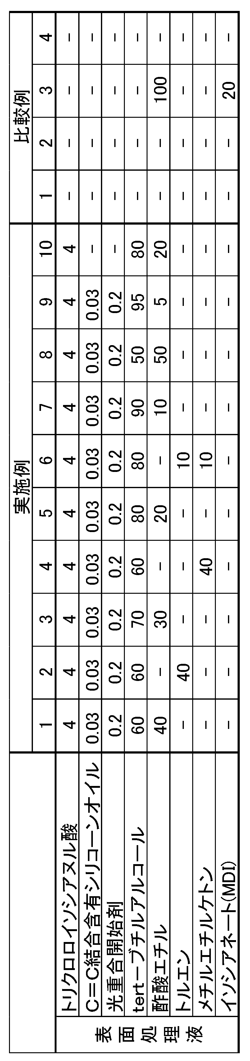
- a surface treatment solution containing trichloroisocyanuric acid or a surface treatment solution containing isocyanate was prepared so as to have the compounding composition (parts by mass) shown in Table 1.
- -Silicone oil containing C C bond: "KF-2012” manufactured by Shin-Etsu Chemical Co., Ltd.
- ⁇ Surface treatment of base layer The surface of the base layer was immersed in a surface treatment liquid whose temperature was adjusted to 25 ° C. for 30 seconds so that a range of 1.0 to 2.0 mm was immersed in the radial direction from the surface of the base layer.
- the base layer pulled up from the surface treatment liquid was immersed in pure water whose temperature was adjusted to 25 ° C. for 30 seconds for washing.
- pure water was removed from the surface of the raised base layer with air, and the base layer was cured by irradiating with ultraviolet rays. Then, heating was performed at 110 ° C. for 2 hours. At this time, a wrinkled convex portion (small convex portion) was formed on the side surface of the large convex portion in the base layer.
- Example 1 The same rubber layer as the unpolished rubber layer in Example 1 was used as it was as the elastic layer of the developing roll without surface treatment.
- Example 2 The same base layer as the base layer having a predetermined large convex portion in Example 1 was used as it was as an elastic layer of a developing roll without surface treatment.
- Example 3 A developing roll was produced in the same manner as in Example 1 except that the same base layer as the base layer having a predetermined large convex portion in Example 1 was surface-treated with a surface treatment liquid containing isocyanate.
- ⁇ Making a developing roll> The outer peripheral surface of the same rubber layer as the unpolished rubber layer in Example 1 is coated with the resin particle dispersion surface layer composition by the roll coating method, and then heat-treated at 170 ° C. for 60 minutes to obtain a surface layer having a thickness of 3 ⁇ m. Formed. From the above, a developing roll having surface irregularities due to the roughness-forming particles was produced.
- Toner filming Using a commercially available color laser printer (“MS812dn” manufactured by LEXMARK) as an evaluation machine, the produced development roll is assembled to a toner cartridge (Bk color), and the image after enduring 10,000 sheets in an environment of 23 ° C ⁇ 53% RH. The case where there is no filming image is regarded as a pass " ⁇ ”, the occurrence of halftone level streaks is regarded as " ⁇ ”, and the occurrence of both solid and halftone streaks is regarded as a fail "x”.
- Toner fusion Using a commercially available color laser printer (“MS812dn” manufactured by LEXMARK) as an evaluation machine, the produced development roll is assembled to a toner cartridge (Bk color), and after printing a solid image in an environment of 23 ° C ⁇ 53% RH, The toner cartridge was left in the evaluation machine at 45 ° C. ⁇ 95% for 5 days. After taking out the toner cartridge from the evaluation machine, the toner cartridge was reassembled in the evaluation machine, and a solid image and a halftone image were printed. A solid image with no contact marks with the doctor blade, toner supply roll, and photoconductor was rated as " ⁇ ", and those with contact marks were rated as "x”.
- the surface roughness of the developing roll (elastic layer) of Comparative Example 2 is formed by polishing, but the small convex portion is not formed on the side surface of the large convex portion formed by polishing, and the surface roughness is large. Toner is deposited in the recesses between the protrusions, and the fusion of the toner cannot be suppressed.
- the surface of the developing roll (elastic layer) of Comparative Example 3 has a surface roughness formed by polishing and is also subjected to surface treatment with isocyanate, but small on the side surface of the large convex portion formed by polishing.
- the convex portion is not formed, and the toner is deposited in the concave portion between the large convex portions, and the fusion of the toner cannot be suppressed.
- Surface roughness due to particles is formed on the surface of the developing roll (surface layer) of Comparative Example 4.
- toner is deposited in the concave portions between the convex portions, and the fusion of the toner cannot be suppressed.
- the toner filming can be suppressed. Then, from the comparison between the tenth embodiment and the other examples, the toner filming can be further suppressed by providing the small convex portion on the side surface of the large convex portion and imparting the silicone group to the surface of the elastic body layer. I understand.
Landscapes
- Physics & Mathematics (AREA)
- General Physics & Mathematics (AREA)
- Engineering & Computer Science (AREA)
- General Engineering & Computer Science (AREA)
- Mechanical Engineering (AREA)
- Dry Development In Electrophotography (AREA)
- Rolls And Other Rotary Bodies (AREA)
Abstract
トナーの融着とトナーフィルミングが抑えられる電子写真機器用現像ロールおよび電子写真機器用現像ロールの製造方法を提供する。 軸体12と、軸体12の外周に形成された弾性体層14と、を備え、弾性体層14の表面に、幅3.0~12μmで高さ3.0~12μmの複数の大凸部16を有するとともに、大凸部16の側面に、十点平均粗さRzが2.0~4.0μmの凹凸を形成する複数の小凸部18を有する電子写真機器用現像ロール10とする。
Description
本発明は、電子写真方式を採用する複写機、プリンター、ファクシミリなどの電子写真機器において好適に用いられる電子写真機器用現像ロールおよび電子写真機器用現像ロールの製造方法に関するものである。
電子写真機器において、現像ロールは、印字に必要な量のトナーを感光体まで運ぶ役割を持っている。現像ロールの表面には、トナー搬送量を確保するため、粗さが付与されている。例えば特許文献1では、現像ロールのゴム弾性層の表面を研磨することにより、ゴム弾性層の表面に粗さが付与されている。また、例えば特許文献2では、アルミナ粒子と樹脂を含有する表面層に紫外線照射などで表面処理し、表面層の表面にアルミナ粒子と樹脂を含む複数の凸部を形成し、その凸部においてアルミナ粒子の一部を露出させることにより、現像部材の表面層の表面に粗さが付与されている。
現像ロールの表面に適切な粗さが付与されていないと、感光体や層形成ブレードとの接地面積が大きくなり、物理的な押し当てによる感光体や層形成ブレードへのトナー融着(トナーフィルミング)が発生する。現像ロールの表面に粗さを付与する方法としては、粗さを形成する粒子を表面層に配合する方法、成形金型内面の粗さをゴム弾性層の表面に転写する方法、ゴム弾性層の表面を研磨する方法などがある。粗さを形成する粒子を表面層に配合する方法においては、粒子が存在する凸部が削れやすく、ここを起点にトナーが融着しやすい。また、いずれの方法においても、凸部と凸部の間の凹部にトナーが堆積することでトナーが融着しやすい。
本発明が解決しようとする課題は、トナーの融着とトナーフィルミングが抑えられる電子写真機器用現像ロールおよび電子写真機器用現像ロールの製造方法を提供することにある。
上記課題を解決するため本発明に係る電子写真機器用現像ロールは、軸体と、前記軸体の外周に形成された弾性体層と、を備え、前記弾性体層の表面に、幅3.0~12μmで高さ3.0~12μmの複数の大凸部を有するとともに、前記大凸部の側面に、十点平均粗さRzが2.0~4.0μmの凹凸を形成する複数の小凸部を有することを要旨とするものである。
前記大凸部は、周方向に連続する線状の凸部であってもよい。前記大凸部は、断面三角形状の凸部であってもよい。前記小凸部は、前記大凸部の側面に形成された皺からなってもよい。さらに、前記大凸部と前記大凸部の間の溝の底部の表面に、Rz2.0~4.0μmの凹凸を形成する複数の小凸部を有してもよい。前記大凸部と前記大凸部の間の距離は、6.0~9.0μmであるとよい。前記小凸部と前記小凸部の間の距離は、1.0~5.0μmであるとよい。前記弾性体層の表面積比S/S0は、5.0~8.0であるとよい。前記弾性体層の表面に、イソシアヌル酸骨格を有する化合物を含むとよい。前記弾性体層は、炭素-炭素二重結合を有するポリマーを含むとよい。
そして、本発明に係る電子写真機器用現像ロールの製造方法は、軸体の外周に、炭素-炭素二重結合を有するポリマーを含み、幅3.0~12μmで高さ3.0~12μmの複数の大凸部を表面に有するベース層を形成する工程と、前記ベース層の表面に塩素化イソシアヌル酸を含浸し、前記塩素化イソシアヌル酸を含浸したベース層の表面を硬化して、前記大凸部の側面に十点平均粗さRzが2.0~4.0μmの凹凸を形成する複数の小凸部を形成する工程と、を有することを要旨とするものである。
本発明に係る電子写真機器用現像ロールによれば、弾性体層の表面に、幅3.0~12μmで高さ3.0~12μmの複数の大凸部を有するとともに、大凸部の側面に、十点平均粗さRzが2.0~4.0μmの凹凸を形成する複数の小凸部を有することから、トナーの融着とトナーフィルミングが抑えられる。
本発明に係る電子写真機器用現像ロール(以下、単に現像ロールということがある。)について詳細に説明する。図1は、一実施形態に係る現像ロールの全体図とそのA-A線断面図であり、図2は、弾性体層の表面の一部Bの拡大図であり、図3は、表面の一部Bの一部Cの拡大図である。図2において、X方向は現像ロールの軸方向であり、Y方向は現像ロールの周方向である。
現像ロール10は、軸体12と、軸体12の外周に形成された弾性体層14と、を備える。弾性体層14は、現像ロール10のベースとなる層(基層)である。弾性体層14は、現像ロール10の径方向の表面に現れる層(最外層)となっている。なお、特に図示しないが、必要に応じて、抵抗調整層等の中間層が、軸体12と弾性体層14の間に配置されていてもよい。
図2に示すように、現像ロール10は、弾性体層14の表面に、幅Wが3.0~12μmで高さHが3.0~12μmの複数の大凸部16を有する。図2に示すように、複数の大凸部16は、断面三角形状の凸部であり、周方向(図2(a)のY方向)に連続する線状の凸部(凸条)となっている。現像ロール10は、弾性体層14の表面に上記する幅・高さの複数の大凸部16を有することで、トナーの搬送性に優れる。また、感光体や層形成ブレードとの接地面積が小さくなり、物理的な押し当てによる感光体や層形成ブレードへのトナー融着(トナーフィルミング)が抑えられる。このような大凸部16が弾性体層14の表面になく、弾性体層14の表面粗さが小さいと、トナーの搬送量が少なく、トナーフィルミングが発生しやすい。大凸部16と大凸部16の間の距離D1は、特に限定されるものではないが、6.0~9.0μmであることが好ましい。大凸部16と大凸部16の間の距離D1が上記範囲であると、適切なトナー搬送性を確保できる。
大凸部16の幅Wは、より好ましくは4.0~11.0μmである。また、大凸部16の高さHは、より好ましくは4.0~10.0μmである。また、大凸部16と大凸部16の間の距離D1は、より好ましくは7.0~18.0μmである。
図2,3に示すように、大凸部16の側面には、十点平均粗さRzが2.0~4.0μmの凹凸を形成する複数の小凸部18を有する。複数の小凸部18は、大凸部16の側面に形成された皺からなる。現像ロール10は、大凸部16の側面に上記する大きさの複数の小凸部18を有することで、大凸部16間に入り込んだトナーが大凸部16間に付着してそのまま堆積するのが抑えられ、現像ロール10へのトナー融着が抑えられる。これは、大凸部16の側面に設けられた複数の小凸部18によるロータス効果によるものと推測される。複数の小凸部18による大凸部16側面の十点平均粗さRzが2.0~4.0μmであることで、通常5.0~14μmの粒径を有するトナーが大凸部16間に留まりにくくなっている。小凸部18と小凸部18の間の距離D2は、特に限定されるものではないが、1.0~5.0μmであることが好ましい。小凸部18と小凸部18の間の距離D2が5.0μm以下であると、小凸部18間にトナーが入り込みにくくなるため、ロータス効果による現像ロール10へのトナー融着を抑える効果が発揮されやすい。
複数の大凸部16と複数の小凸部18を有する弾性体層14は、次のようにして作製することができる。
まず、軸体12の外周に、炭素-炭素二重結合を有するポリマーを含み、幅3.0~12μmで高さ3.0~12μmの複数の大凸部16を表面に有するベース層を形成する。
ベース層の大凸部16の側面には、まだ複数の小凸部18は形成されていない。ベース層は、炭素-炭素二重結合を有するポリマーを含む弾性体層形成用のゴム組成物を金型にて成形後、得られたゴム層の表面を研磨することにより、作製することができる。大凸部16を周方向に連続する線状の凸部(凸条)とするには、周方向に沿って研磨すればよい。また、例えば楔形の研磨材を用いることで、大凸部16を断面三角形の凸部とすることができる。ベース層の大凸部16は、金型内面に所定の粗さを付与しておき、金型成形において金型内面の粗さを転写することにより形成してもよい。
次に、ベース層の表面に塩素化イソシアヌル酸を含浸し、塩素化イソシアヌル酸を含浸したベース層の表面を硬化して、大凸部16の側面に十点平均粗さRzが2.0~4.0μmの凹凸を形成する複数の小凸部18を形成する。
所定の大きさの複数の大凸部16を有するベース層の表面に塩素化イソシアヌル酸を含浸すると、ベース層の含浸された領域は膨張する。そして、塩素化イソシアヌル酸を含浸したベース層の表面を硬化すると、ベース層の含浸した領域は収縮する。この際、表面と内部に収縮差が生じ、表面よりも内部がより収縮する。これにより、表面に皺が発生し、大凸部16の側面に、皺状の複数の小凸部18が形成される。このような収縮差による皺の発生は、複数の大凸部16を有するベース層に塩素化イソシアヌル酸を含浸することで起こる。複数の大凸部16を有していないゴム層に塩素化イソシアヌル酸を含浸しても、このような皺の発生は見られない。また、複数の大凸部16を有するベース層に塩素化イソシアヌル酸以外の化合物、例えばイソシアネートを含浸しても、このような皺の発生は見られない。
ベース層への塩素化イソシアヌル酸の含浸は、塩素化イソシアヌル酸を含む表面処理液を用いて行うことができる。塩素化イソシアヌル酸としては、モノクロロイソシアヌル酸、ジクロロイソシアヌル酸、トリクロロイソシアヌル酸、これらの塩などを挙げることができる。表面処理液には、塩素化イソシアヌル酸を溶解あるいは分散させる溶媒などが含まれるとよい。溶解させる溶媒としては、酢酸エチル、トルエン、メチルエチルケトン(MEK)、アセトンなどを挙げることができる。分散させる溶媒としては、ターシャリーブチルアルコール(TBA)などを挙げることができる。溶媒は、溶解させるもの1~2種と、分散させるもの1種を組み合わせて用いるとよい。溶解させる溶媒としては、極性が高く、皺状の複数の小凸部18が形成されやすいなどの観点から、トルエン、メチルエチルケトンがより好ましい。大凸部16の側面の十点平均粗さRzの大きさは、塩素化イソシアヌル酸の含浸量や、塩素化イソシアヌル酸を希釈する溶媒量、溶媒種などによって調整することができる。例えば、溶解させる溶媒として極性の高い溶媒を用いると、含浸深さが深くなり、表面と内部の収縮差が大きくなって、十点平均粗さRzが大きくなりやすい。
表面処理液には、シリコーン化合物やフッ素含有化合物などの弾性体層14表面のタック性を下げる改質成分が含まれていてもよい。シリコーン化合物やフッ素含有化合物は、弾性体層14のポリマー成分と化学結合により結合されるとよい。このようなシリコーン化合物としては、炭素-炭素二重結合を有するシリコーン化合物や炭素-炭素二重結合を有するフッ素含有化合物などを挙げることができる。炭素-炭素二重結合を有するシリコーン化合物や炭素-炭素二重結合を有するフッ素含有化合物を弾性体層14のポリマー成分と化学結合させるには、塩素化イソシアヌル酸としてジクロロイソシアヌル酸やトリクロロイソシアヌル酸を用いるか、光重合開始剤を用いるとよい。
炭素-炭素二重結合を有するシリコーン化合物としては、シリコーン基を有するアクリル系モノマーを挙げることができる。アクリル系モノマーは、(メタ)アクリレート、(メタ)アクリルアミドを表す。(メタ)アクリレートは、アクリレートとメタアクリレートを総称するものである。(メタ)アクリルアミドは、アクリルアミドとメタアクリルアミドを総称するものである。
シリコーン基としては、ジメチルシリコーン基、ジエチルシリコーン基、ジフェニルシリコーン基などを挙げることができる。炭素-炭素二重結合を有するシリコーン化合物は、数平均分子量で200~30000の範囲のものなどを好適に用いることができる。
炭素-炭素二重結合を有するフッ素含有化合物としては、フッ素含有基を有するアクリル系モノマーを挙げることができる。アクリル系モノマーは、(メタ)アクリレート、(メタ)アクリルアミドを表す。(メタ)アクリレートは、アクリレートとメタアクリレートを総称するものである。(メタ)アクリルアミドは、アクリルアミドとメタアクリルアミドを総称するものである。
フッ素含有基としては、炭素数1~20のフルオロアルキル基が挙げられる。フルオロアルキル基は、アルキル基の全ての水素原子がフッ素原子に置換されたパーフルオロアルキル基であってもよいし、アルキル基の一部の水素原子がフッ素原子に置換されたフルオロアルキル基であってもよい。炭素数1~20のフルオロアルキル基としては、トリフルオロメチル基、ペンタフルオロエチル基、ヘプタフルオロプロピル基、ノナフルオロブチル基、トリフルオロエチル基、ペンタフルオロプロピル基、ヘプタフルオロブチル基などが挙げられる。
光重合開始剤は、光重合性化合物の光重合を開始させるものであれば特に限定されず、例えば、アルキルフェノン類、アセトフェノン類、ベンゾインエーテル類、ベンゾフェノン類、チオキサントン類、アントラキノン類、ベンジル類、ビアセチル類等の光重合開始剤を挙げることができる。具体的には、例えば、ベンジルジメチルケタール、2-ヒドロキシ-2-メチル-1-フェニル-プロパン-1-オン、メチル-O-ベンゾイルベンゾエート、1-ヒドロキシシクロヘキシルフェニルケトンなどを挙げることができる。
表面処理液における光重合開始剤の含有量は、炭素-炭素二重結合を有するシリコーン化合物および炭素-炭素二重結合を有するフッ素含有化合物の合計1質量部に対し、10~100質量部の範囲内が好ましい。より好ましくは10~20質量部の範囲内である。
表面処理液の含浸方法は、特に限定されるものではなく、ディッピング法、ロールコート法、スプレーコート法などを用いることができる。表面処理における表面処理液の温度は、特に限定されるものではなく、常温~100℃くらいまでの温度を適宜選択すればよい。表面処理液の接触時間は、特に限定されるものではなく、数秒~数時間くらいまでの時間を適宜選択すればよい。
炭素-炭素二重結合を有するポリマーを含むベース層に表面処理液を含浸すると、常温下で、塩素化イソシアヌル酸が炭素-炭素二重結合に付加反応し、イソシアヌル酸骨格がベース層のポリマーに結合する。表面処理液が、塩素化イソシアヌル酸とともに炭素-炭素二重結合を有するシリコーン化合物や炭素-炭素二重結合を有するフッ素含有化合物を含む場合、炭素-炭素二重結合を有するポリマーを含むベース層に表面処理液を含浸すると、塩素化イソシアヌル酸がシリコーン化合物やフッ素含有化合物の炭素-炭素二重結合にも付加反応し、ベース層のポリマーに結合するイソシアヌル酸骨格を介してシリコーン化合物やフッ素含有化合物がベース層のポリマーに結合する。また、光重合開始剤を配合していれば、ベース層の炭素-炭素二重結合を有するポリマーと炭素-炭素二重結合を有するシリコーン化合物や炭素-炭素二重結合を有するフッ素含有化合物が架橋反応し、シリコーン化合物やフッ素含有化合物がベース層の表面のポリマーに直接、結合する。これにより、弾性体層14の表面のタック性を下げることができる。そして、弾性体層14の表面のタック性が下がることで、トナーフィルミングを抑える効果が向上する。
炭素-炭素二重結合を有するポリマーとしては、イソプレンゴム(IR)、ブタジエンゴム(BR)、アクリロニトリルブタジエンゴム(NBR)、スチレンブタジエンゴム(SBR)、クロロプレンゴム(CR)、ブチルゴム(IIR)、エチレンプロピレンジエンゴム(EPDM)、天然ゴム(NR)などを挙げることができる。これらのうちでは、イソプレンゴム(IR)、ブタジエンゴム(BR)、アクリロニトリルブタジエンゴム(NBR)が特に好ましい。
弾性体層形成用のゴム組成物は、必要に応じて、導電性付与のため、カーボンブラック、グラファイト、c-TiO2、c-ZnO、c-SnO2(c-は、導電性を意味する。)、イオン導電剤(4級アンモニウム塩、ホウ酸塩、界面活性剤など)などの従来より公知の導電剤を適宜添加することができる。また、必要に応じて、各種添加剤を適宜添加しても良い。添加剤としては、滑剤、加硫促進剤、老化防止剤、光安定剤、粘度調整剤、加工助剤、難燃剤、可塑剤、発泡剤、充填剤、分散剤、消泡剤、顔料、離型剤などを挙げることができる。
架橋剤としては、樹脂架橋剤、硫黄架橋剤、過酸化物架橋剤、脱塩素架橋剤を挙げることができる。これらの架橋剤は、単独で用いても良いし、2種以上組み合わせて用いても良い。
樹脂架橋剤としては、フェノール樹脂、ユリア樹脂、アミノ樹脂、グアナキミン樹脂、キシレン樹脂、不飽和ポリエステル樹脂、ジアリルフタレート樹脂、エポキシ樹脂、ウレタン樹脂などの従来より公知の樹脂架橋剤を挙げることができる。
硫黄架橋剤としては、粉末硫黄、沈降硫黄、コロイド硫黄、表面処理硫黄、不溶性硫黄、塩化硫黄、チウラム系加硫促進剤、高分子多硫化物などの従来より公知の硫黄架橋剤を挙げることができる。
過酸化物架橋剤としては、パーオキシケタール、ジアルキルパーオキサイド、パーオキシエステル、ケトンパーオキサイド、パーオキシジカーボネート、ジアシルパーオキサイド、ハイドロパーオキサイドなどの従来より公知の過酸化物架橋剤を挙げることができる。
脱塩素架橋剤としては、ジチオカーボネート化合物を挙げることができる。より具体的には、キノキサリン-2,3-ジチオカーボネート、6-メチルキノキサリン-2,3-ジチオカーボネート、6-イソプロピルキノキサリン-2,3-ジチオカーボネート、5,8-ジメチルキノキサリン-2,3-ジチオカーボネートなどを挙げることができる。
架橋剤の配合量としては、ブリードしにくいなどの観点から、未架橋ゴム100質量部に対して、好ましくは0.1~2質量部の範囲内、より好ましくは0.3~1.8質量部の範囲内、さらに好ましくは0.5~1.5質量部の範囲内である。
架橋剤として脱塩素架橋剤を用いる場合には、脱塩素架橋促進剤を併用しても良い。脱塩素架橋促進剤としては、1,8-ジアザビシクロ(5,4,0)ウンデセン-7(以下、DBUと略称する。)もしくはその弱酸塩を挙げることができる。脱塩素架橋促進剤は、DBUの形態として用いても良いが、その取り扱い面から、その弱酸塩の形態として用いることが好ましい。DBUの弱酸塩としては、炭酸塩、ステアリン酸塩、2-エチルヘキシル酸塩、安息香酸塩、サリチル酸塩、3-ヒドロキシ-2-ナフトエ酸塩、フェノール樹脂塩、2-メルカプトベンゾチアゾール塩、2-メルカプトベンズイミダゾール塩などを挙げることができる。
脱塩素架橋促進剤の含有量としては、ブリードしにくいなどの観点から、未架橋ゴム100質量部に対して、0.1~2質量部の範囲内であることが好ましい。より好ましくは0.3~1.8質量部の範囲内、さらに好ましくは0.5~1.5質量部の範囲内である。
弾性体層14には、導電性付与のため、カーボンブラック、グラファイト、c-TiO2、c-ZnO、c-SnO2(c-は、導電性を意味する。)、イオン導電剤(4級アンモニウム塩、ホウ酸塩、界面活性剤など)などの従来より公知の導電剤を適宜添加することができる。また、必要に応じて、各種添加剤を適宜添加しても良い。添加剤としては、滑剤、加硫促進剤、老化防止剤、光安定剤、粘度調整剤、加工助剤、難燃剤、可塑剤、発泡剤、充填剤、分散剤、消泡剤、顔料、離型剤などを挙げることができる。
弾性体層14は、架橋ゴムの種類、イオン導電剤の配合量、電子導電剤の配合などにより、所定の体積抵抗率に調整することができる。弾性体層14の体積抵抗率は、用途などに応じて102~1010Ω・cm、103~109Ω・cm、104~108Ω・cmの範囲などに適宜設定すればよい。
弾性体層14の厚みは、特に限定されるものではなく、用途などに応じて0.1~10mmの範囲内などで適宜設定すればよい。
弾性体層14は、複数の大凸部16と複数の小凸部18を有することで、表面積の大きいものとなっている。弾性体層14の表面積比S/S0は、5.0~8.0であることが好ましい。より好ましくは6.0~8.0である。ここで、Sは、弾性体層14の実測表面積であり、S0は、弾性体層14の表面が平坦面であるとしたときの理論表面積である。
弾性体層14は、その表面凹凸形状に特徴があるものであるから、その表面凹凸形状を維持するため、弾性体層14の表面を覆う層(表層)が設けられていないことが好ましい。
軸体12は、導電性を有するものであれば特に限定されない。具体的には、鉄、ステンレス、アルミニウムなどの金属製の中実体、中空体からなる芯金などを例示することができる。軸体12の表面には、必要に応じて、接着剤、プライマーなどを塗布しても良い。つまり、弾性体層14は、接着剤層(プライマー層)を介して軸体12に接着されていてもよい。接着剤、プライマーなどには、必要に応じて導電化を行っても良い。
以上の構成の現像ロール10によれば、弾性体層14の表面に、幅3.0~12μmで高さ3.0~12μmの複数の大凸部16を有するとともに、大凸部16の側面に、十点平均粗さRzが2.0~4.0μmの凹凸を形成する複数の小凸部18を有することから、トナーの融着とトナーフィルミングが抑えられる。
以上、本発明の実施形態について説明したが、本発明は上記実施形態に何ら限定されるものではなく、本発明の趣旨を逸脱しない範囲内で種々の改変が可能である。
例えば上記実施形態では、複数の大凸部16は断面三角形状の凸部であるが、大凸部16の断面形状は三角形状に限られるものではない。また、上記実施形態では、複数の大凸部16は周方向に連続する線状の凸部(凸条)となっているが、周方向以外の方向に連続する線状の凸部(凸条)であってもよいし、所定の方向に連続しない非線状の凸部であってもよい。また、上記実施形態では、大凸部16と大凸部16の間には平坦部がないものであるが、大凸部16と大凸部16の間に平坦部があってもよい。また、その平坦部など、大凸部16と大凸部16の間の溝の底部の表面に、Rz2.0~4.0μmの凹凸を形成する複数の小凸部18を有していてもよい。
また、上記実施形態では、複数の小凸部18は大凸部16の側面に形成された皺からなるが、複数の小凸部18は皺以外の形状の凸部であってもよい。また、複数の小凸部18は凸条の大凸部16の側面に、周方向に沿って延びる凸条などで形成されていてもよい。
以下、実施例および比較例を用いて本発明を詳細に説明する。
(実施例1~10)
<弾性体層形成用ゴム組成物の調製>
NBR(日本ゼオン製「Nipol DN3335」)100質量部に対し、過酸化物架橋剤(日本油脂製「パーヘキサ25B」)を1.0質量部、イオン導電剤(テトラn-ブチルアンモニウムパークロレート)を1.0質量部、カーボンブラック(東海カーボン製「シースト116」)を1.0質量部添加し、これらを攪拌機により撹拌、混合して弾性体層形成用ゴム組成物を調製した。
<弾性体層形成用ゴム組成物の調製>
NBR(日本ゼオン製「Nipol DN3335」)100質量部に対し、過酸化物架橋剤(日本油脂製「パーヘキサ25B」)を1.0質量部、イオン導電剤(テトラn-ブチルアンモニウムパークロレート)を1.0質量部、カーボンブラック(東海カーボン製「シースト116」)を1.0質量部添加し、これらを攪拌機により撹拌、混合して弾性体層形成用ゴム組成物を調製した。
<ベース層の作製>
成形金型(パイプ状)に芯金(軸体、直径6mm)をセットし、上記の弾性体層形成用ゴム組成物を注入し、170℃で30分加熱した後、冷却、脱型して、芯金の外周に厚み5mmのゴム層を形成した。次いで、ゴム層の軸方向全体をゴム層の周方向に研磨することにより、図2に示すような断面三角形状の凸部が周方向に連続する線状の凸部(大凸部)をゴム層の表面に形成した。以上により、所定の大凸部を有するベース層を芯金の外周に有するロール体を作製した。ベース層における大凸部の幅W、高さH、凸間距離D1の値は、表2に示した通りである。
成形金型(パイプ状)に芯金(軸体、直径6mm)をセットし、上記の弾性体層形成用ゴム組成物を注入し、170℃で30分加熱した後、冷却、脱型して、芯金の外周に厚み5mmのゴム層を形成した。次いで、ゴム層の軸方向全体をゴム層の周方向に研磨することにより、図2に示すような断面三角形状の凸部が周方向に連続する線状の凸部(大凸部)をゴム層の表面に形成した。以上により、所定の大凸部を有するベース層を芯金の外周に有するロール体を作製した。ベース層における大凸部の幅W、高さH、凸間距離D1の値は、表2に示した通りである。
<表面処理液の調製>
表1に記載の配合組成(質量部)となるように、トリクロロイソシアヌル酸を含有する表面処理液あるいはイソシアネートを含有する表面処理液を調製した。
・C=C結合含有シリコーンオイル:信越化学工業製「KF-2012」
・光重合開始剤:IGM製「Omnirad1173」
・イソシアネート(MDI、4,4’-ジフェニルメタンジイソシアネート):日本ポリウレタン工業製「ミリオネートMT」
表1に記載の配合組成(質量部)となるように、トリクロロイソシアヌル酸を含有する表面処理液あるいはイソシアネートを含有する表面処理液を調製した。
・C=C結合含有シリコーンオイル:信越化学工業製「KF-2012」
・光重合開始剤:IGM製「Omnirad1173」
・イソシアネート(MDI、4,4’-ジフェニルメタンジイソシアネート):日本ポリウレタン工業製「ミリオネートMT」
<ベース層の表面処理>
ベース層の表面から径方向内部に1.0~2.0mmの範囲が浸漬するように、25℃に温度調節した表面処理液中にベース層の表面を30秒間浸漬した。次いで、表面処理液から引き上げたベース層を25℃に温度調節した純水中に30秒間浸漬して洗浄した。次いで、引き上げたベース層の表面からエアーで純水を除去し、紫外線照射してベース層を硬化させた。その後、110℃2時間熱入れを行った。このとき、ベース層における大凸部の側面に皺状の凸部(小凸部)が形成された。以上により、所定の凹凸形状を有する弾性体層を芯金の外周に有する現像ロールを作製した。弾性体層における小凸部に起因する大凸部側面の表面粗さRz、小凸部間距離D2、弾性体層の表面粗さRz、弾性体層の表面積比S/S0は、表2に示した通りである。
ベース層の表面から径方向内部に1.0~2.0mmの範囲が浸漬するように、25℃に温度調節した表面処理液中にベース層の表面を30秒間浸漬した。次いで、表面処理液から引き上げたベース層を25℃に温度調節した純水中に30秒間浸漬して洗浄した。次いで、引き上げたベース層の表面からエアーで純水を除去し、紫外線照射してベース層を硬化させた。その後、110℃2時間熱入れを行った。このとき、ベース層における大凸部の側面に皺状の凸部(小凸部)が形成された。以上により、所定の凹凸形状を有する弾性体層を芯金の外周に有する現像ロールを作製した。弾性体層における小凸部に起因する大凸部側面の表面粗さRz、小凸部間距離D2、弾性体層の表面粗さRz、弾性体層の表面積比S/S0は、表2に示した通りである。
(比較例1)
実施例1における研磨していないゴム層と同じゴム層を表面処理しないでそのまま現像ロールの弾性体層とした。
実施例1における研磨していないゴム層と同じゴム層を表面処理しないでそのまま現像ロールの弾性体層とした。
(比較例2)
実施例1における所定の大凸部を有するベース層と同じベース層を表面処理しないでそのまま現像ロールの弾性体層とした。
実施例1における所定の大凸部を有するベース層と同じベース層を表面処理しないでそのまま現像ロールの弾性体層とした。
(比較例3)
実施例1における所定の大凸部を有するベース層と同じベース層を、イソシアネートを含有する表面処理液で表面処理した以外は実施例1と同様にして、現像ロールを作製した。
実施例1における所定の大凸部を有するベース層と同じベース層を、イソシアネートを含有する表面処理液で表面処理した以外は実施例1と同様にして、現像ロールを作製した。
(比較例4)
<樹脂粒子分散表層組成物の調製>
ウレタン樹脂(ニッポラン5199、日本ポリウレタン社製)100質量部に対して、カーボンブラック(デンカブラックHS-100、電気化学工業社製)10質量部、粗さ形成用粒子としての平均粒径8μmのウレタン粒子(根上工業社製「アートパールC800」)15質量部をボールミルを用いて混練した後、MEK400質量部を加えて混合・攪拌することにより樹脂粒子分散表層組成物を調製した。
<樹脂粒子分散表層組成物の調製>
ウレタン樹脂(ニッポラン5199、日本ポリウレタン社製)100質量部に対して、カーボンブラック(デンカブラックHS-100、電気化学工業社製)10質量部、粗さ形成用粒子としての平均粒径8μmのウレタン粒子(根上工業社製「アートパールC800」)15質量部をボールミルを用いて混練した後、MEK400質量部を加えて混合・攪拌することにより樹脂粒子分散表層組成物を調製した。
<現像ロールの作製>
実施例1における研磨していないゴム層と同じゴム層の外周面に、ロールコート法により、樹脂粒子分散表層組成物をコーティングした後、170℃で60分熱処理して、厚さ3μmの表層を形成した。以上により、粗さ形成用粒子に起因する表面凹凸を有する現像ロールを作製した。
実施例1における研磨していないゴム層と同じゴム層の外周面に、ロールコート法により、樹脂粒子分散表層組成物をコーティングした後、170℃で60分熱処理して、厚さ3μmの表層を形成した。以上により、粗さ形成用粒子に起因する表面凹凸を有する現像ロールを作製した。
作製した現像ロールについて、トナーフィルミングの発生状況、トナー融着の発生状況を調べた。
(大凸部の幅W)
レーザー顕微鏡(キーエンス製「VK-X100」)を用いて、ロール表面の両端からそれぞれ軸方向内側5mmの位置および軸方向中央の3つの位置において、表面を3000倍で撮影した。モードの平面計測にて、任意の大凸部の頂点と隣の凹部の底点に計測ラインを引き、計測した平面距離を2倍してその任意の大凸部の幅とした。1箇所につき任意の3つの大凸部について実施し、3箇所各3つの計9点の平均値を大凸部の幅とした。
レーザー顕微鏡(キーエンス製「VK-X100」)を用いて、ロール表面の両端からそれぞれ軸方向内側5mmの位置および軸方向中央の3つの位置において、表面を3000倍で撮影した。モードの平面計測にて、任意の大凸部の頂点と隣の凹部の底点に計測ラインを引き、計測した平面距離を2倍してその任意の大凸部の幅とした。1箇所につき任意の3つの大凸部について実施し、3箇所各3つの計9点の平均値を大凸部の幅とした。
(大凸部の高さH)
レーザー顕微鏡(キーエンス製「VK-X100」)を用いて、ロール表面の両端からそれぞれ軸方向内側5mmの位置および軸方向中央の3つの位置において、表面を3000倍で撮影した。モードのプロファイル計測にて、任意の大凸部の頂点を通過する計測ラインを引き、計測した高さプロファイルにおいて、ノイズを除去するために高さスムージングを行い、さらにグラフの傾きを補正した。任意の大凸部の頂点と隣の凹部の底点とを選択し、得られた高度差の数値をその任意の凸部の高さとした。1箇所につき任意の3つの大凸部について実施し、3箇所各3つの計9点の平均値を大凸部の高さとした。
レーザー顕微鏡(キーエンス製「VK-X100」)を用いて、ロール表面の両端からそれぞれ軸方向内側5mmの位置および軸方向中央の3つの位置において、表面を3000倍で撮影した。モードのプロファイル計測にて、任意の大凸部の頂点を通過する計測ラインを引き、計測した高さプロファイルにおいて、ノイズを除去するために高さスムージングを行い、さらにグラフの傾きを補正した。任意の大凸部の頂点と隣の凹部の底点とを選択し、得られた高度差の数値をその任意の凸部の高さとした。1箇所につき任意の3つの大凸部について実施し、3箇所各3つの計9点の平均値を大凸部の高さとした。
(大凸部の凸間距離D1)
レーザー顕微鏡(キーエンス製「VK-X100」)を用いて、ロール表面の両端からそれぞれ軸方向内側5mmの位置および軸方向中央の3つの位置において、表面を3000倍で撮影した。モードの平面計測にて、任意の大凸部の頂点と隣の凸部の頂点に計測ラインを引き、計測した平面距離を凸間距離とした。1箇所につき任意の3つの大凸部間について実施し、3箇所各3つの計9点の平均値を大凸部の凸間距離とした。
レーザー顕微鏡(キーエンス製「VK-X100」)を用いて、ロール表面の両端からそれぞれ軸方向内側5mmの位置および軸方向中央の3つの位置において、表面を3000倍で撮影した。モードの平面計測にて、任意の大凸部の頂点と隣の凸部の頂点に計測ラインを引き、計測した平面距離を凸間距離とした。1箇所につき任意の3つの大凸部間について実施し、3箇所各3つの計9点の平均値を大凸部の凸間距離とした。
(大凸部側面の表面粗さRz)
レーザー顕微鏡(キーエンス製「VK-X100」)を用いて、ロール表面の両端からそれぞれ軸方向内側5mmの位置および軸方向中央の3つの位置において、表面を3000倍で撮影した。撮影した画像から、粗さ測定(JIS B 0601-1994に準拠)モードの線粗さ測定にて、任意の大凸部を3箇所選択し、その側面の十点平均粗さRzを測定した。3箇所各3つの計9点の平均値を大凸部側面の表面粗さRzとした。なお、測定距離は4~6μmで測定した。
レーザー顕微鏡(キーエンス製「VK-X100」)を用いて、ロール表面の両端からそれぞれ軸方向内側5mmの位置および軸方向中央の3つの位置において、表面を3000倍で撮影した。撮影した画像から、粗さ測定(JIS B 0601-1994に準拠)モードの線粗さ測定にて、任意の大凸部を3箇所選択し、その側面の十点平均粗さRzを測定した。3箇所各3つの計9点の平均値を大凸部側面の表面粗さRzとした。なお、測定距離は4~6μmで測定した。
(小凸部の凸間距離D2)
レーザー顕微鏡(キーエンス製「VK-X100」)を用いて、ロール表面の両端からそれぞれ軸方向内側5mmの位置および軸方向中央の3つの位置において、表面を3000倍で撮影した。プロファイル測定モードにて任意の大凸部の側面に計測ラインを引き、プロファイルを取得した。プロファイルから隣り合う小凸部を選択し、その平面距離を測定した。上記を任意の3つの小凸部間において実施し、3箇所各3つの計9点の平均値を小凸部の凸間距離D2とした。
レーザー顕微鏡(キーエンス製「VK-X100」)を用いて、ロール表面の両端からそれぞれ軸方向内側5mmの位置および軸方向中央の3つの位置において、表面を3000倍で撮影した。プロファイル測定モードにて任意の大凸部の側面に計測ラインを引き、プロファイルを取得した。プロファイルから隣り合う小凸部を選択し、その平面距離を測定した。上記を任意の3つの小凸部間において実施し、3箇所各3つの計9点の平均値を小凸部の凸間距離D2とした。
(ロール表面の表面粗さRz)
接触式表面粗さ計(東京精密社製「サーフコム1400D」)を用いて、ロール表面の両端からそれぞれ軸方向内側5mmの位置および軸方向中央の3つの位置において、周方向4点、計12点の十点平均粗さRzを測定した。平均値をロール表面のRzとし、算出基準はJIS B 0601-1994に準拠した。測定長さは4mm、カットオフ波長は0.8mmで実施した。
接触式表面粗さ計(東京精密社製「サーフコム1400D」)を用いて、ロール表面の両端からそれぞれ軸方向内側5mmの位置および軸方向中央の3つの位置において、周方向4点、計12点の十点平均粗さRzを測定した。平均値をロール表面のRzとし、算出基準はJIS B 0601-1994に準拠した。測定長さは4mm、カットオフ波長は0.8mmで実施した。
(表面積比S/S0の測定方法)
レーザー顕微鏡(キーエンス製「VK-X100」)を用いて、ロール表面の両端からそれぞれ軸方向内側5mmの位置および軸方向中央の3つの位置において、表面を3000倍で撮影した。モードの体積表面計測にて、0.4mm2の範囲の表面積Sを求め、S0で割ったもの(S/S0)を表面積比とした。Sは、弾性体層の実測表面積であり、S0は、弾性体層の表面が平坦面であるとしたときの理論表面積である。
レーザー顕微鏡(キーエンス製「VK-X100」)を用いて、ロール表面の両端からそれぞれ軸方向内側5mmの位置および軸方向中央の3つの位置において、表面を3000倍で撮影した。モードの体積表面計測にて、0.4mm2の範囲の表面積Sを求め、S0で割ったもの(S/S0)を表面積比とした。Sは、弾性体層の実測表面積であり、S0は、弾性体層の表面が平坦面であるとしたときの理論表面積である。
(トナーフィルミング)
市販のカラーレーザープリンター(LEXMARK社製「MS812dn」を評価機とし、作製した現像ロールをトナーカートリッジ(Bk色)に組付け、23℃×53%RHの環境下で10000枚耐久後の画像で、フィルミング画像が無い場合を合格「○」とし、ハーフトーンレベルのスジ発生を「△」とし、ベタ、ハーフトーンの両方のスジ発生を不合格「×」とした。
市販のカラーレーザープリンター(LEXMARK社製「MS812dn」を評価機とし、作製した現像ロールをトナーカートリッジ(Bk色)に組付け、23℃×53%RHの環境下で10000枚耐久後の画像で、フィルミング画像が無い場合を合格「○」とし、ハーフトーンレベルのスジ発生を「△」とし、ベタ、ハーフトーンの両方のスジ発生を不合格「×」とした。
(トナー融着)
市販のカラーレーザープリンター(LEXMARK社製「MS812dn 」を評価機とし、作製した現像ロールをトナーカートリッジ(Bk色)に組付け、23℃×53%RHの環境下で1枚ベタ画像を印字後、トナーカートリッジを評価機にセットしたまま45℃×95%の環境に5日間放置した。評価機からトナーカートリッジを取出し後、再度評価機にトナーカートリッジを組み付け、ベタ画像、ハーフトーン画像を印字した。ベタ画像にドクターブレード、トナー供給ロール、感光体との当接痕がみられないものを合格「○」、当接痕が見られるものを不合格「×」とした。
市販のカラーレーザープリンター(LEXMARK社製「MS812dn 」を評価機とし、作製した現像ロールをトナーカートリッジ(Bk色)に組付け、23℃×53%RHの環境下で1枚ベタ画像を印字後、トナーカートリッジを評価機にセットしたまま45℃×95%の環境に5日間放置した。評価機からトナーカートリッジを取出し後、再度評価機にトナーカートリッジを組み付け、ベタ画像、ハーフトーン画像を印字した。ベタ画像にドクターブレード、トナー供給ロール、感光体との当接痕がみられないものを合格「○」、当接痕が見られるものを不合格「×」とした。

比較例1の現像ロールの表面には、研磨や粒子などによる表面粗さが形成されておらず、比較例1の現像ロールでは、トナーフィルミングが抑えられない。比較例2の現像ロール(弾性体層)の表面には、研磨による表面粗さは形成されているが、研磨によって形成された大凸部の側面に小凸部は形成されておらず、大凸部間の凹部にトナーが堆積し、トナーの融着が抑えられない。比較例3の現像ロール(弾性体層)の表面には、研磨による表面粗さが形成されており、イソシアネートによる表面処理も施されているが、研磨によって形成された大凸部の側面に小凸部は形成されておらず、大凸部間の凹部にトナーが堆積し、トナーの融着が抑えられない。比較例4の現像ロール(表層)の表面には、粒子による表面粗さは形成されている。しかし、比較例4の現像ロールでは、凸部間の凹部にトナーが堆積し、トナーの融着が抑えられない。
実施例と比較例1の比較から、弾性体層に表面凹凸が設けられていないと、トナーフィルミングが抑えられないことがわかる。そして、実施例と比較例2~4の比較から、弾性体層に表面凹凸が設けられていても、トナーの融着が抑えられないことがあることがわかる。そして、実施例から、研磨などで弾性体層の表面に設けた大凸部の側面に小凸部が設けられ、大凸部の側面の表面粗さが所定の表面粗さRzとなるようにすることで、トナーが大凸部間に入っても大凸部間においてトナーの付着が抑えられ、トナーの融着が抑えられる。また、弾性体層に表面凹凸が設けられているため、トナーフィルミングも抑えられる。そして、実施例10とその他の実施例の比較から、大凸部の側面に小凸部を設けるとともに弾性体層の表面にシリコーン基を付与することで、より一層、トナーフィルミングが抑えられることがわかる。
以上、本発明の実施例について説明したが、本発明は上記実施例に何ら限定されるものではなく、本発明の趣旨を逸脱しない範囲内で種々の改変が可能である。
Claims (11)
- 軸体と、前記軸体の外周に形成された弾性体層と、を備え、
前記弾性体層の表面に、幅3.0~12μmで高さ3.0~12μmの複数の大凸部を有するとともに、前記大凸部の側面に、十点平均粗さRzが2.0~4.0μmの凹凸を形成する複数の小凸部を有することを特徴とする電子写真機器用現像ロール。 - 前記大凸部が、周方向に連続する線状の凸部であることを特徴とする請求項1に記載の電子写真機器用現像ロール。
- 前記大凸部が、断面三角形状の凸部であることを特徴とする請求項1または2に記載の電子写真機器用現像ロール。
- 前記小凸部が、前記大凸部の側面に形成された皺からなることを特徴とする請求項1から3のいずれか1項に記載の電子写真機器用現像ロール。
- さらに、前記大凸部と前記大凸部の間の溝の底部の表面に、Rz2.0~4.0μmの凹凸を形成する複数の小凸部を有することを特徴とする請求項1から4のいずれか1項に記載の電子写真機器用現像ロール。
- 前記大凸部と前記大凸部の間の距離が、6.0~9.0μmであることを特徴とする請求項1から5のいずれか1項に記載の電子写真機器用現像ロール。
- 前記小凸部と前記小凸部の間の距離が、1.0~5.0μmであることを特徴とする請求項1から6のいずれか1項に記載の電子写真機器用現像ロール。
- 前記弾性体層の表面積比S/Soが、5.0~8.0であることを特徴とする請求項1から7のいずれか1項に記載の電子写真機器用現像ロール。
S:前記弾性体層の実測表面積
S0:前記弾性体層の表面が平坦面であるとしたときの理論表面積 - 前記弾性体層の表面に、イソシアヌル酸骨格を有する化合物を含むことを特徴とする請求項1から8のいずれか1項に記載の電子写真機器用現像ロール。
- 前記弾性体層が、炭素-炭素二重結合を有するポリマーを含むことを特徴とする請求項1から9のいずれか1項に記載の電子写真機器用現像ロール。
- 軸体の外周に、炭素-炭素二重結合を有するポリマーを含み、幅3.0~12μmで高さ3.0~12μmの複数の大凸部を表面に有するベース層を形成する工程と、
前記ベース層の表面に塩素化イソシアヌル酸を含浸し、前記塩素化イソシアヌル酸を含浸したベース層の表面を硬化して、前記大凸部の側面に十点平均粗さRzが2.0~4.0μmの凹凸を形成する複数の小凸部を形成する工程と、
を有することを特徴とする電子写真機器用現像ロールの製造方法。
Priority Applications (2)
| Application Number | Priority Date | Filing Date | Title |
|---|---|---|---|
| CN202080006303.8A CN113056617B (zh) | 2019-03-27 | 2020-02-25 | 电子照相设备用显影辊以及电子照相设备用显影辊的制造方法 |
| US17/225,108 US11194266B2 (en) | 2019-03-27 | 2021-04-08 | Developing roll for electrophotographic device |
Applications Claiming Priority (2)
| Application Number | Priority Date | Filing Date | Title |
|---|---|---|---|
| JP2019060235A JP7146682B2 (ja) | 2019-03-27 | 2019-03-27 | 電子写真機器用現像ロールおよび電子写真機器用現像ロールの製造方法 |
| JP2019-060235 | 2019-03-27 |
Related Child Applications (1)
| Application Number | Title | Priority Date | Filing Date |
|---|---|---|---|
| US17/225,108 Continuation US11194266B2 (en) | 2019-03-27 | 2021-04-08 | Developing roll for electrophotographic device |
Publications (1)
| Publication Number | Publication Date |
|---|---|
| WO2020195449A1 true WO2020195449A1 (ja) | 2020-10-01 |
Family
ID=72609029
Family Applications (1)
| Application Number | Title | Priority Date | Filing Date |
|---|---|---|---|
| PCT/JP2020/007322 Ceased WO2020195449A1 (ja) | 2019-03-27 | 2020-02-25 | 電子写真機器用現像ロールおよび電子写真機器用現像ロールの製造方法 |
Country Status (4)
| Country | Link |
|---|---|
| US (1) | US11194266B2 (ja) |
| JP (1) | JP7146682B2 (ja) |
| CN (1) | CN113056617B (ja) |
| WO (1) | WO2020195449A1 (ja) |
Families Citing this family (2)
| Publication number | Priority date | Publication date | Assignee | Title |
|---|---|---|---|---|
| WO2024024600A1 (ja) * | 2022-07-27 | 2024-02-01 | キヤノン株式会社 | 容器、容器の製造方法およびトナー容器 |
| CN115648006A (zh) * | 2022-10-24 | 2023-01-31 | 苏州市创怡盛实业有限公司 | 一种表面处理装置及表面处理方法 |
Citations (7)
| Publication number | Priority date | Publication date | Assignee | Title |
|---|---|---|---|---|
| JPH07114265A (ja) * | 1993-10-15 | 1995-05-02 | Seiko Epson Corp | 現像装置 |
| JPH08286502A (ja) * | 1995-02-15 | 1996-11-01 | Bridgestone Corp | 静電潜像の現像方法及び現像装置 |
| JP2008116500A (ja) * | 2006-10-31 | 2008-05-22 | Shin Etsu Polymer Co Ltd | ローラの製造方法、ローラ及び画像形成装置 |
| JP2009075497A (ja) * | 2007-09-25 | 2009-04-09 | Tokai Rubber Ind Ltd | 電子写真機器用現像ロール |
| JP2012241735A (ja) * | 2011-05-16 | 2012-12-10 | Tokai Rubber Ind Ltd | ゴムロール、型および型の製造方法 |
| JP2013073130A (ja) * | 2011-09-29 | 2013-04-22 | Tokai Rubber Ind Ltd | 電子写真機器用現像ロール |
| JP2017058615A (ja) * | 2015-09-18 | 2017-03-23 | キヤノン株式会社 | 現像剤担持体 |
Family Cites Families (25)
| Publication number | Priority date | Publication date | Assignee | Title |
|---|---|---|---|---|
| JP3066834B2 (ja) | 1990-06-06 | 2000-07-17 | 東ソー株式会社 | 強誘電体薄膜の製造方法 |
| US6096395A (en) * | 1992-12-16 | 2000-08-01 | Tokai Rubber Industries, Ltd. | Roll including foam body and method of producing the roll |
| US5565968A (en) * | 1994-09-02 | 1996-10-15 | Bridgestone Corporation | Developing roller, and method and apparatus for developing latent images using the roller |
| CA2254838C (en) * | 1997-12-26 | 2007-06-19 | Nitto Kogyo Co., Ltd. | Developing roller and method of producing the same |
| JP2003033991A (ja) * | 2001-07-25 | 2003-02-04 | Sumitomo Bakelite Co Ltd | 表示素子用プラスチック基板 |
| JP2004034537A (ja) * | 2002-07-04 | 2004-02-05 | Canon Chemicals Inc | トナー搬送ローラ成形型およびその製造方法 |
| JP4442812B2 (ja) | 2003-04-22 | 2010-03-31 | シンジーテック株式会社 | 現像ロール |
| JP4957116B2 (ja) * | 2006-08-08 | 2012-06-20 | コニカミノルタビジネステクノロジーズ株式会社 | トナー供給ローラ |
| JP2008158023A (ja) * | 2006-12-21 | 2008-07-10 | Toray Ind Inc | プラズマディスプレイ用フィルター |
| JP5209398B2 (ja) * | 2008-07-28 | 2013-06-12 | 東海ゴム工業株式会社 | 電子写真機器用現像ロール |
| CN102224461B (zh) * | 2008-10-08 | 2014-06-11 | 株式会社普利司通 | 调色剂输送辊、辊制造用模具以及辊的制造方法 |
| JP5720688B2 (ja) * | 2010-08-27 | 2015-05-20 | 大日本印刷株式会社 | 光学積層体、偏光板及び画像表示装置 |
| JP5662825B2 (ja) * | 2011-02-14 | 2015-02-04 | 住友理工株式会社 | 電子写真機器用現像ロール |
| CN103245981B (zh) * | 2012-02-14 | 2017-03-01 | 大日本印刷株式会社 | 光学层叠体、偏振片和图像显示装置 |
| JP2014073489A (ja) * | 2012-09-12 | 2014-04-24 | Turner Shikisai Kk | エラストマー塗装方法、ゴム塗装面変色防止剤およびゴム用塗料 |
| JP2015151246A (ja) * | 2014-02-17 | 2015-08-24 | シンジーテック株式会社 | 給紙搬送分離用ロール及びその製造方法 |
| JP2015184427A (ja) * | 2014-03-24 | 2015-10-22 | 大日本印刷株式会社 | 反射防止物品、画像表示装置、反射防止物品の製造方法、反射防止物品の賦型用金型、及び賦型用金型の製造方法 |
| JP2015187637A (ja) * | 2014-03-26 | 2015-10-29 | 大日本印刷株式会社 | 反射防止物品、画像表示装置、反射防止物品の製造方法、反射防止物品の賦型用金型、及び賦型用金型の製造方法 |
| JP6413554B2 (ja) * | 2014-09-26 | 2018-10-31 | 富士ゼロックス株式会社 | 転写装置および画像形成装置 |
| US9981323B2 (en) * | 2015-07-16 | 2018-05-29 | Kennametal Inc. | Double-sided tangential cutting insert and cutting tool system using the same |
| WO2017094883A1 (ja) * | 2015-12-04 | 2017-06-08 | 東ソー株式会社 | ポリイソシアネート組成物およびそれを用いた塗料組成物 |
| US9952531B2 (en) | 2016-04-28 | 2018-04-24 | Canon Kabushiki Kaisha | Developing member having alumina particles exposed within protrusions |
| JP2017207736A (ja) * | 2016-05-16 | 2017-11-24 | 恵和株式会社 | 液晶表示装置用光学シート、液晶表示装置用バックライトユニット及び液晶表示装置用光学シートの製造方法 |
| JP7128571B2 (ja) * | 2017-02-07 | 2022-08-31 | 大日本印刷株式会社 | 低屈折率層用組成物 |
| JP7336289B2 (ja) * | 2018-07-31 | 2023-08-31 | キヤノン株式会社 | 電子写真用部材、電子写真プロセスカートリッジ及び電子写真画像形成装置 |
-
2019
- 2019-03-27 JP JP2019060235A patent/JP7146682B2/ja active Active
-
2020
- 2020-02-25 CN CN202080006303.8A patent/CN113056617B/zh active Active
- 2020-02-25 WO PCT/JP2020/007322 patent/WO2020195449A1/ja not_active Ceased
-
2021
- 2021-04-08 US US17/225,108 patent/US11194266B2/en active Active
Patent Citations (7)
| Publication number | Priority date | Publication date | Assignee | Title |
|---|---|---|---|---|
| JPH07114265A (ja) * | 1993-10-15 | 1995-05-02 | Seiko Epson Corp | 現像装置 |
| JPH08286502A (ja) * | 1995-02-15 | 1996-11-01 | Bridgestone Corp | 静電潜像の現像方法及び現像装置 |
| JP2008116500A (ja) * | 2006-10-31 | 2008-05-22 | Shin Etsu Polymer Co Ltd | ローラの製造方法、ローラ及び画像形成装置 |
| JP2009075497A (ja) * | 2007-09-25 | 2009-04-09 | Tokai Rubber Ind Ltd | 電子写真機器用現像ロール |
| JP2012241735A (ja) * | 2011-05-16 | 2012-12-10 | Tokai Rubber Ind Ltd | ゴムロール、型および型の製造方法 |
| JP2013073130A (ja) * | 2011-09-29 | 2013-04-22 | Tokai Rubber Ind Ltd | 電子写真機器用現像ロール |
| JP2017058615A (ja) * | 2015-09-18 | 2017-03-23 | キヤノン株式会社 | 現像剤担持体 |
Also Published As
| Publication number | Publication date |
|---|---|
| JP2020160303A (ja) | 2020-10-01 |
| JP7146682B2 (ja) | 2022-10-04 |
| CN113056617B (zh) | 2023-01-31 |
| CN113056617A (zh) | 2021-06-29 |
| US11194266B2 (en) | 2021-12-07 |
| US20210223714A1 (en) | 2021-07-22 |
Similar Documents
| Publication | Publication Date | Title |
|---|---|---|
| US8376922B2 (en) | Developing roller, charging roller, conductive roller and method for producing the same | |
| JP5612805B2 (ja) | 帯電ロール | |
| JP5486217B2 (ja) | 多層ベルト | |
| JP6714529B2 (ja) | 電子写真機器用帯電部材および電子写真機器用帯電部材の製造方法 | |
| CN101866128A (zh) | 带电辊及其制造方法 | |
| JP2004233607A (ja) | 半導電性ロール | |
| US11194266B2 (en) | Developing roll for electrophotographic device | |
| WO2011096471A1 (ja) | 電子写真機器用現像ロール | |
| JP6909623B2 (ja) | 電子写真機器用現像ロール | |
| JP4001123B2 (ja) | 導電性ロール | |
| JP2010008440A (ja) | 電子写真機器用転写ロールおよびその製造方法 | |
| JP2009139924A (ja) | 電子写真機器用転写ロール | |
| WO2019188893A1 (ja) | 電子写真機器用現像ロール | |
| JP2018017943A (ja) | 電子写真機器用導電性ロール | |
| JP2017156396A (ja) | 電子写真機器用帯電ロール | |
| CN101078903A (zh) | 具有高光泽涂料层的熔凝元件 | |
| EP4521170B1 (en) | Conductive member for electrophotographic devices | |
| JP2007271731A (ja) | 帯電ロール | |
| JP6722613B2 (ja) | 電子写真機器用帯電ロール | |
| US20230236529A1 (en) | Conductive member, transfer device, process cartridge, and image forming apparatus | |
| JP5363012B2 (ja) | 電子写真機器用帯電ロール | |
| JP7079719B2 (ja) | 電子写真機器用導電性部材 | |
| CN118202307A (zh) | 电子照相设备用带电辊以及电子照相设备用带电辊的制造方法 | |
| CN111381475A (zh) | 显影辊及其制造方法 | |
| JP2005352169A (ja) | 帯電ローラ及びそれを備えた画像形成装置 |
Legal Events
| Date | Code | Title | Description |
|---|---|---|---|
| 121 | Ep: the epo has been informed by wipo that ep was designated in this application |
Ref document number: 20776523 Country of ref document: EP Kind code of ref document: A1 |
|
| NENP | Non-entry into the national phase |
Ref country code: DE |
|
| 122 | Ep: pct application non-entry in european phase |
Ref document number: 20776523 Country of ref document: EP Kind code of ref document: A1 |