WO2020194725A1 - Procédé de commande de dispositif d'alimentation en gaz et dispositif d'alimentation en gaz - Google Patents
Procédé de commande de dispositif d'alimentation en gaz et dispositif d'alimentation en gaz Download PDFInfo
- Publication number
- WO2020194725A1 WO2020194725A1 PCT/JP2019/013826 JP2019013826W WO2020194725A1 WO 2020194725 A1 WO2020194725 A1 WO 2020194725A1 JP 2019013826 W JP2019013826 W JP 2019013826W WO 2020194725 A1 WO2020194725 A1 WO 2020194725A1
- Authority
- WO
- WIPO (PCT)
- Prior art keywords
- air supply
- supply line
- valve
- gas
- endoscope
- Prior art date
Links
- 238000000034 method Methods 0.000 title claims description 77
- 239000007788 liquid Substances 0.000 claims description 92
- 238000004140 cleaning Methods 0.000 description 19
- 239000000243 solution Substances 0.000 description 19
- XLYOFNOQVPJJNP-UHFFFAOYSA-N water Substances O XLYOFNOQVPJJNP-UHFFFAOYSA-N 0.000 description 18
- 239000000126 substance Substances 0.000 description 17
- 230000008929 regeneration Effects 0.000 description 8
- 238000011069 regeneration method Methods 0.000 description 8
- 238000004659 sterilization and disinfection Methods 0.000 description 5
- 239000012530 fluid Substances 0.000 description 4
- 230000001105 regulatory effect Effects 0.000 description 4
- 230000001954 sterilising effect Effects 0.000 description 4
- 230000005514 two-phase flow Effects 0.000 description 4
- 239000000645 desinfectant Substances 0.000 description 3
- 230000000249 desinfective effect Effects 0.000 description 3
- 238000003780 insertion Methods 0.000 description 3
- 230000037431 insertion Effects 0.000 description 3
- KFSLWBXXFJQRDL-UHFFFAOYSA-N Peracetic acid Chemical compound CC(=O)OO KFSLWBXXFJQRDL-UHFFFAOYSA-N 0.000 description 2
- 238000004891 communication Methods 0.000 description 2
- 244000005700 microbiome Species 0.000 description 2
- LFQSCWFLJHTTHZ-UHFFFAOYSA-N Ethanol Chemical compound CCO LFQSCWFLJHTTHZ-UHFFFAOYSA-N 0.000 description 1
- 230000005856 abnormality Effects 0.000 description 1
- 230000032683 aging Effects 0.000 description 1
- 239000007864 aqueous solution Substances 0.000 description 1
- 238000007599 discharging Methods 0.000 description 1
- 230000000694 effects Effects 0.000 description 1
- 238000001914 filtration Methods 0.000 description 1
- 230000005484 gravity Effects 0.000 description 1
- 238000011086 high cleaning Methods 0.000 description 1
- 230000002093 peripheral effect Effects 0.000 description 1
- 238000010248 power generation Methods 0.000 description 1
- 230000003584 silencer Effects 0.000 description 1
- 230000000007 visual effect Effects 0.000 description 1
- 238000005406 washing Methods 0.000 description 1
Images


Classifications
-
- A—HUMAN NECESSITIES
- A61—MEDICAL OR VETERINARY SCIENCE; HYGIENE
- A61B—DIAGNOSIS; SURGERY; IDENTIFICATION
- A61B1/00—Instruments for performing medical examinations of the interior of cavities or tubes of the body by visual or photographical inspection, e.g. endoscopes; Illuminating arrangements therefor
- A61B1/00131—Accessories for endoscopes
-
- A—HUMAN NECESSITIES
- A61—MEDICAL OR VETERINARY SCIENCE; HYGIENE
- A61B—DIAGNOSIS; SURGERY; IDENTIFICATION
- A61B1/00—Instruments for performing medical examinations of the interior of cavities or tubes of the body by visual or photographical inspection, e.g. endoscopes; Illuminating arrangements therefor
- A61B1/012—Instruments for performing medical examinations of the interior of cavities or tubes of the body by visual or photographical inspection, e.g. endoscopes; Illuminating arrangements therefor characterised by internal passages or accessories therefor
- A61B1/015—Control of fluid supply or evacuation
-
- A—HUMAN NECESSITIES
- A61—MEDICAL OR VETERINARY SCIENCE; HYGIENE
- A61M—DEVICES FOR INTRODUCING MEDIA INTO, OR ONTO, THE BODY; DEVICES FOR TRANSDUCING BODY MEDIA OR FOR TAKING MEDIA FROM THE BODY; DEVICES FOR PRODUCING OR ENDING SLEEP OR STUPOR
- A61M39/00—Tubes, tube connectors, tube couplings, valves, access sites or the like, specially adapted for medical use
- A61M39/22—Valves or arrangement of valves
-
- A—HUMAN NECESSITIES
- A61—MEDICAL OR VETERINARY SCIENCE; HYGIENE
- A61B—DIAGNOSIS; SURGERY; IDENTIFICATION
- A61B1/00—Instruments for performing medical examinations of the interior of cavities or tubes of the body by visual or photographical inspection, e.g. endoscopes; Illuminating arrangements therefor
- A61B1/00064—Constructional details of the endoscope body
- A61B1/00066—Proximal part of endoscope body, e.g. handles
- A61B1/00068—Valve switch arrangements
-
- A—HUMAN NECESSITIES
- A61—MEDICAL OR VETERINARY SCIENCE; HYGIENE
- A61B—DIAGNOSIS; SURGERY; IDENTIFICATION
- A61B1/00—Instruments for performing medical examinations of the interior of cavities or tubes of the body by visual or photographical inspection, e.g. endoscopes; Illuminating arrangements therefor
- A61B1/00112—Connection or coupling means
- A61B1/00121—Connectors, fasteners and adapters, e.g. on the endoscope handle
-
- A—HUMAN NECESSITIES
- A61—MEDICAL OR VETERINARY SCIENCE; HYGIENE
- A61B—DIAGNOSIS; SURGERY; IDENTIFICATION
- A61B1/00—Instruments for performing medical examinations of the interior of cavities or tubes of the body by visual or photographical inspection, e.g. endoscopes; Illuminating arrangements therefor
- A61B1/12—Instruments for performing medical examinations of the interior of cavities or tubes of the body by visual or photographical inspection, e.g. endoscopes; Illuminating arrangements therefor with cooling or rinsing arrangements
-
- A—HUMAN NECESSITIES
- A61—MEDICAL OR VETERINARY SCIENCE; HYGIENE
- A61M—DEVICES FOR INTRODUCING MEDIA INTO, OR ONTO, THE BODY; DEVICES FOR TRANSDUCING BODY MEDIA OR FOR TAKING MEDIA FROM THE BODY; DEVICES FOR PRODUCING OR ENDING SLEEP OR STUPOR
- A61M2205/00—General characteristics of the apparatus
- A61M2205/33—Controlling, regulating or measuring
- A61M2205/3331—Pressure; Flow
- A61M2205/3355—Controlling downstream pump pressure
Definitions
- the present invention relates to a control method and an air supply device for an air supply device that sends gas discharged from a compressor into an endoscope line.
- Some endoscopes used in the medical field have a conduit.
- a gas having a pressure higher than the atmospheric pressure discharged from the compressor may be sent into the conduit provided by the endoscope.
- Japanese Patent No. 5642907 discloses an endoscope cleaning and disinfecting apparatus having a configuration for sending gas into a conduit provided in an endoscope.
- the gas that the endoscope cleaning and disinfecting device sends into the pipe of the endoscope is used to discharge the liquid or the like in the pipe to the outside of the pipe.
- Japanese Patent No. 1737816 discloses an endoscope device that sends a gas to be discharged from a nozzle provided at the tip of an insertion portion of an endoscope into a conduit provided in the endoscope. ing. The gas sent by the endoscope device into the conduit provided by the endoscope is used for draining the observation window.
- the pressure of the gas sent into the conduit provided by the endoscope is within a predetermined range.
- the pressure of the gas discharged by the compressor may fluctuate due to aging of parts constituting the compressor, fluctuations in the voltage and frequency supplied to the motor for driving the compressor, and the like.
- An object of the present invention is to solve the above-mentioned points, and to provide an air supply device capable of sending a gas discharged from a compressor into an endoscope line with a pressure within a predetermined range. To do.
- the control method of the air supply device includes an endoscope connection portion connected to the endoscope conduit, a compressor connection portion connected to a compressor for deriving gas, and one end of the endoscope. Between the air supply line connected to the connection part and the other end connected to the compressor connection part, the on-off valve arranged in the air supply line, and the other end and the on-off valve in the air supply line.
- a control method for an air supply device including an air release valve that is connected and capable of adjusting the amount of gas released from the air supply line to the atmosphere, and a sensor that detects the internal pressure of the air supply line.
- step I With the valve closed, a gas is introduced into the air supply line from the compressor, and step I in which the sensor detects the internal pressure of the air supply line and the internal pressure of the air supply line fall within a predetermined reference range.
- step II for adjusting the amount of gas released from the open-air valve to the atmosphere and the amount of open-air gas adjusted in step II, the on-off valve is closed and the air is sent from the compressor.
- step III of introducing the gas into the air duct the on-off valve is opened in a state where the gas is introduced into the air supply pipe from the compressor and the internal pressure of the air supply pipe is within a predetermined range, and the air supply is fed.
- step IV which derives the gas in the tracheal tract from the endoscope connection.
- an endoscope connection portion connected to the endoscope conduit, a compressor connection portion connected to a compressor for deriving gas, and one end thereof are connected to the endoscope.
- Step II in which the amount of gas released from the air release valve to the atmosphere was adjusted so that the internal pressure of the air supply pipe line was within a predetermined reference range, and the amount of open air adjusted in step II were maintained.
- the on-off valve is closed and gas is introduced from the compressor into the air supply line, and the gas is introduced from the compressor into the air supply line, and the internal pressure of the air supply line is predetermined.
- Step IV in which the on-off valve is opened and the gas in the air supply pipe line is led out from the endoscope connection portion, is executed.
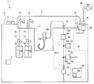
- the air supply device 60 of the present embodiment is a device that sends gas into the endoscope conduit 120 included in the endoscope 100. As shown in FIG. 1, as an example in the present embodiment, the air supply device 60 is included in the endoscope reprocessor 1.
- the endoscope reprocessor 1 is a device that performs a regeneration process on at least one of an endoscope and an endoscope accessory.
- the regeneration treatment referred to here is not particularly limited, and is a rinsing treatment with water, a cleaning treatment for removing stains such as organic substances, a disinfection treatment for disabling predetermined microorganisms, and a sterilization treatment for eliminating or killing all microorganisms. Alternatively, any combination of these may be used.
- the air supply device 60 is not limited to the form included in the endoscope reprocessor 1.
- the air supply device 60 may be included in a dryer that dries the endoscope 100.
- the air supply device 60 may be in a form of sending gas to be sent from the tip end portion of the insertion portion of the endoscope 100 when the endoscope 100 is used.
- the endoscope reprocessor 1 includes a control unit 69, a power supply unit 6, a processing tank 2, a compressor 70, and an air supply device 60.
- the control unit 69 includes a processor, a memory, an input / output device, a power control device, and the like, executes a predetermined program according to an instruction from the user, and controls the operation of each part constituting the endoscope reprocessor 1. It has a configuration. The operation of each configuration included in the endoscope reprocessor 1 and the air supply device 60 in the following description is controlled by the control unit 69 even if not particularly described.
- the control unit 69 constitutes an air supply device 60, which will be described later.
- the control unit 69 includes a storage unit 69a such as a flash memory that stores information on the adjustment state of the atmospheric release valve 65, which will be described later.
- the operation unit 7 and the display unit 8 constitute a user interface for exchanging information between the control unit 69 and the user.
- the operation unit 7 includes an operation member such as a push switch or a touch sensor that receives an operation instruction from the user.
- the operation instruction from the user is converted into an electric signal by the operation unit 7 and input to the control unit 69.
- the operation instruction from the user is, for example, an instruction to start the reproduction process.
- the display unit 8 includes, for example, a display device for displaying images and characters, a light emitting device for emitting light, a speaker for emitting sound, a vibrator for emitting vibration, or a combination thereof.
- the display unit 8 outputs information to the user from the control unit 69.
- a part or all of the operation unit 7 and the display unit 8 is provided in an electronic device separated from the main body 1a of the endoscope reprocessor 1 that performs wired communication or wireless communication with the control unit 69. It may be.
- the power supply unit 6 supplies electric power to each configuration of the endoscope reprocessor 1.
- the power supply unit 6 distributes electric power obtained from the outside such as a commercial power source to each configuration.
- the power supply unit 6 may include a power generation device and a battery.
- the processing tank 2 has a concave shape having an opening, and can store a liquid inside.
- One or more endoscopes 100 can be arranged in the processing tank 2.
- the upper part refers to the position farther from the ground with respect to the comparison target
- the lower part refers to the position closer to the ground with respect to the comparison target
- the height in the following description indicates the height relationship along the direction of gravity.
- a lid 3 for opening and closing the opening of the processing tank 2 is provided on the upper part of the processing tank 2.
- the opening of the processing tank 2 is closed by the lid 3.
- the lid 3 is provided with an opening provided with a filter. Even when the treatment tank 2 is closed by the lid 3, the pressure inside the treatment tank 2 is equivalent to the atmospheric pressure.
- the treatment tank 2 is provided with a cleaning liquid nozzle 15, a chemical liquid nozzle 12, a water nozzle 14, and an internal visual connection portion 61. Although not shown, the treatment tank 2 is provided with a discharge port for discharging the liquid existing inside.
- the cleaning liquid nozzle 15 is an opening that communicates with the cleaning liquid tank 50 that stores the cleaning liquid via the cleaning liquid pipeline 51.
- the cleaning liquid is used for the cleaning treatment.
- a cleaning liquid pump 52 is provided in the cleaning liquid pipeline 51.
- the cleaning liquid pump 52 is connected to the control unit 69, and the operation of the cleaning liquid pump 52 is controlled by the control unit 69. By operating the cleaning liquid pump 52, the cleaning liquid in the cleaning liquid tank 50 is transferred into the processing tank 2.
- the chemical solution nozzle 12 is an opening that communicates with the chemical solution tank 20 via the chemical solution pipeline 26.
- the chemical solution tank 20 stores the chemical solution.
- the type of chemical solution stored in the chemical solution tank 20 is not particularly limited, but as an example in the present embodiment, the chemical solution is a disinfectant solution used for disinfection treatment or a sterilization solution used for sterilization treatment. Examples of the disinfectant solution or sterilizing solution include an aqueous solution of peracetic acid.
- a chemical solution pump 27 is provided in the chemical solution pipeline 26. By operating the chemical solution pump 27, the chemical solution in the chemical solution tank 20 is transferred into the treatment tank 2 via the chemical solution pipeline 26 and the chemical solution nozzle 12.
- the water nozzle 14 is a pipeline that communicates with the water supply source connecting portion 46 via the water supply pipeline 43.
- the water supply source connection unit 46 is connected to a water supply source 49 such as a water supply facility that delivers water via, for example, a hose.
- a water introduction valve 45 is provided in the water supply line 43.
- the water introduction valve 45 is connected to the control unit 69, and the operation of the water introduction valve 45 is controlled by the control unit 69. By opening the water introduction valve 45, the water supplied from the water supply source 49 is introduced into the treatment tank 2.
- the endoscope connection unit 61 constitutes an air supply device 60, which will be described later.
- the endoscope connection portion 61 is connected to the endoscope conduit 120 of the endoscope 100 arranged in the processing tank 2.
- the endoscope connection portion 61 may be directly connected to the endoscope conduit 120, or may be connected to the endoscope conduit 120 via a tube or the like.
- the compressor 70 discharges a gas having a pressure higher than the atmospheric pressure.
- the type of gas discharged by the compressor 70 is not particularly limited, but in the present embodiment, the compressor 70 compresses and discharges air.
- the compressor 70 is electrically connected to the control unit 69, and the operation of the compressor 70 is controlled by the control unit 69.
- the air supply device 60 includes an air supply pipe line 63, an endoscope connection unit 61, a compressor connection unit 62, an on-off valve 64, an atmosphere release valve 65, a sensor 66, and a control unit 69.
- the air supply device 60 executes an air supply process for feeding the gas introduced from the compressor 70 into the endoscope line 120.
- the air supply line 63 is a hollow line that opens at both one end 63a, which is the first end, and the other end 63b, which is the second end.
- One end 63a of the air supply line 63 is connected to the endoscope connection portion 61. Further, the other end 63b of the air supply pipe line 63 is connected to the compressor connecting portion 62.
- the endoscope connection unit 61 can be connected to the endoscope conduit 120 of the endoscope 100.
- the endoscope line 120 is connected to the endoscope connection portion 61, one end 63a of the air supply line 63 and the endoscope line 120 communicate with each other.
- the compressor connection portion 62 is connected to the compressor 70.
- the other end 63b of the air supply line 63 communicates with the compressor 70 via the compressor connection portion 62. That is, the gas discharged by the compressor 70 is introduced into the air supply pipe line 63 through the compressor connection portion 62.
- the on-off valve 64 is provided in the air supply pipe line 63.
- the on-off valve 64 is a so-called two-port solenoid valve including two ports, a first port 64a and a second port 64b.
- the first port 64a communicates with the other end 63b side of the air supply line 63.
- the second port 64b communicates with one end 63a side of the air supply pipe line 63.
- the on-off valve 64 is electrically connected to the control unit 69, and the operation of the on-off valve 64 is controlled by the control unit 69.
- the on-off valve 64 When the on-off valve 64 is in the open state, the flow path between the first port 64a and the second port 64b is opened, and a fluid can flow from the first port 64a to the second port 64b.
- the on-off valve 64 When the on-off valve 64 is in the closed state, the flow path between the first port 64a and the second port 64b is shielded.
- the air release valve 65 is connected to the first section 63c, which is a section between the other end 63b and the on-off valve 64 in the air supply line 63.
- the air release valve 65 can adjust the amount of gas released to the atmosphere from within the first section 63c of the air supply line 63.
- the atmosphere release valve 65 is electrically connected to the control unit 69, and the operation of the atmosphere release valve 65 is controlled by the control unit 69.
- the air release valve 65 includes an input port 65a communicating with the first section 63c of the air supply line 63, and an output port 65b open to the atmosphere.
- the number of input ports 65a and output ports 65b is not limited, and may be one or a plurality.
- the output port 65b is not limited to a form that is directly opened to the atmosphere.
- the output port 65b may be connected to a container whose internal pressure is substantially atmospheric pressure, and may be open to the atmosphere via the container.
- the container constitutes, for example, a device that captures the liquid existing in the fluid discharged from the output port 65b. Further, the output port 65b may be provided with a filter or a silencer.
- the "atmospheric release amount" of the gas from the first section 63c of the air supply line 63 adjusted by the atmosphere release valve 65 is specifically when the internal pressure (atmospheric pressure) of the first section 63c is higher than the atmospheric pressure.
- it is the flow rate of the gas discharged from the inside of the first section 63c to the outside of the first section 63c via the atmosphere release valve 65.
- the flow rate is represented by the volume of the gas discharged from the inside of the first section 63c to the outside of the first section 63c per predetermined unit time. That is, the atmosphere release valve 65 has a configuration that changes (adjusts) the flow rate of the gas flowing from the input port 65a to the output port 65b.
- the range of adjusting the amount of air release by the air release valve 65 may include the case where the flow rate of the gas discharged from the inside of the first section 63c to the outside of the first section 63c is zero. That is, the atmosphere release valve 65 may have a configuration that shields the flow path between the input port 65a and the output port 65b.
- the air release valve 65 adjusts the amount of air release is not particularly limited.
- the air release valve 65 has a configuration in which the amount of air opening is adjusted by changing the cross-sectional area of the flow path between the input port 65a and the output port 65b.
- the atmospheric release valve 65 of the present embodiment includes a plurality of two-port solenoid valves having a predetermined flow path cross section. One port of the plurality of solenoid valves communicates with the input port 65a, and the other port is connected to the output port 65b.
- the atmospheric release valve 65 of the present embodiment having such a configuration changes the cross-sectional area of the flow path between the input port 65a and the output port 65b by changing the number of solenoid valves to be opened.
- the atmospheric release valve 65 of the present embodiment is inexpensive because it is composed of a simple two-port solenoid valve, and is easy to control.
- the atmosphere release valve 65 may be provided with a mechanism for continuously changing the cross-sectional area of the flow path between the input port 65a and the output port 65b. Further, the atmospheric release valve 65 includes an electromagnetic valve that opens and closes a flow path between the input port 65a and the output port 65b, and the time during which the solenoid valve is closed and the time during which the solenoid valve is open within a predetermined unit time. The amount of air released to the atmosphere may be adjusted by changing the ratio (duty ratio) of.
- the sensor 66 is a pressure sensor that detects the internal pressure of the first section 63c of the air supply line 63.
- the sensor 66 is electrically connected to the control unit 69.
- the sensor 66 is arranged between the on-off valve 64 and the atmosphere release valve 65 in the first section 63c of the air supply line 63, but the sensor 66 is in the atmosphere in the first section 63c. It may be arranged between the release valve 65 and the other end 63b.
- a filter for filtering gas may be provided in the first section 63c of the air supply pipe line 63.
- the control unit 69 controls the operation of the air supply device 60 having the above configuration.
- 2, 3 and 4 are flowcharts showing a control method of the air supply device 60.
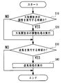
- the control unit 69 repeatedly executes the process shown in FIG. 2 at a predetermined cycle when the power of the air supply device 60 (endoscope reprocessor 1) is turned on. As shown in FIG. 2, the control unit 69 determines in step S10 whether or not it is time to adjust the air release valve 65.
- step S10 When the control unit 69 determines in step S10 that it is time to adjust the air release valve 65, the process proceeds to step S20, the adjustment process of the air release valve 65 is executed, and then the process proceeds to step S30. .. In step S10, when the control unit 69 determines that it is not time to adjust the air release valve 65, the control unit 69 skips step S20 and proceeds to step S30.
- the criteria for determining whether or not it is time to adjust the air release valve 65 in step S10 is not particularly limited.
- control unit 69 executes step S10 for the first time after the power of the air supply device 60 (endoscope reprocessor 1) is turned on, it is time to adjust the atmosphere release valve 65.
- the control unit 69 of the present embodiment determines that it is time to adjust the atmosphere release valve 65 in step S10 before executing the first air supply process on the day.
- the control unit 69 stores, for example, the date and time when the adjustment of the atmosphere release valve 65 was executed in the past in the storage unit 69a, and when the elapsed time from the stored date and time exceeds a predetermined value, the atmosphere in step S10. It is determined that it is time to adjust the release valve 65. In this case, the control unit 69 adjusts the air release valve 65 when the elapsed time from the stored date and time exceeds a predetermined value and before the first air supply process of the day is executed. It may be determined that.
- control unit 69 stores the date and time when the adjustment of the air release valve 65 was executed in the past in the storage unit 69a, and when the operating time of the compressor 70 from the stored date and time exceeds a predetermined value, the step. It is determined that it is time to adjust the air release valve 65 in S10.
- control unit 69 may determine whether or not it is time to adjust the atmosphere release valve 65 in step S10 based on the presence or absence of an instruction from the user via the operation unit 7.
- step S30 the control unit 69 determines whether or not it is time to execute the air supply process into the endoscope line 120.
- step S30 determines in step S30 that it is time to execute the air supply process
- the control unit 69 proceeds to step S40 to execute the air supply process, and then ends the process shown in FIG.
- step S30 when the control unit 69 determines that it is not the time to execute the air supply process, the control unit 69 skips step S40 and ends the process shown in FIG.
- the time for executing the air supply process is predetermined during the period in which the endoscope reprocessor 1 performs the regeneration process on the endoscope 100. Since the timing of performing the air supply process in the regeneration process by the endoscope reprocessor 1 is the same as the conventional one, detailed description thereof will be omitted.
- FIG. 3 is a flowchart of the adjustment process of the atmospheric release valve 65.
- the endoscope conduit 120 may or may not be connected to the endoscope connection portion 61.
- step S100 the control unit 69 closes the on-off valve 64.
- step S110 the control unit 69 starts the operation of the compressor 70, and starts the introduction of gas from the compressor 70 into the first section 63c of the air supply line 63.
- step S120 the control unit 69 starts detecting the internal pressure of the first section 63c of the air supply line 63 based on the output from the sensor 66.
- the execution of steps S100, S110, and S120 may be performed in a different order or at the same time.
- step S130 the control unit 69 adjusts the amount of air release of the air release valve 65 so that the internal pressure of the first section 63c of the air supply line 63 falls within a predetermined reference range.
- the predetermined reference range is the range of atmospheric pressure that is appropriate for the gas sent into the endoscope line 120 in the regeneration process.
- the predetermined reference range is set to the minimum atmospheric pressure Pmin or more and the maximum atmospheric pressure Pmax or less.
- the minimum atmospheric pressure Pmin in the reference range is higher than the atmospheric pressure required for the gas sent into the endoscope line 120 in the regeneration process.
- the maximum atmospheric pressure Pmax in the reference range is lower than the upper limit of the atmospheric pressure allowed in the endoscope line 120 and lower than the specified maximum atmospheric pressure of the gas discharged by the compressor 70.
- step S130 if the internal pressure of the first section 63c is higher than the maximum atmospheric pressure Pmax in the reference range, the control unit 69 increases the amount of air release of the atmospheric release valve 65. In the present embodiment, if the internal pressure of the first section 63c is higher than the maximum atmospheric pressure Pmax in the reference range, the control unit 69 determines the cross-sectional area of the flow path between the input port 65a and the output port 65b of the atmosphere release valve 65. Enlarge.
- the control unit 69 reduces the amount of air release of the air release valve 65.
- the control unit 69 determines the cross-sectional area of the flow path between the input port 65a and the output port 65b of the atmosphere release valve 65. Make it smaller.
- step S140 the control unit 69 stores in the storage unit 69a the adjusted state of the atmospheric release valve 65 whose reference range is the internal pressure of the first section 63c.
- the control unit 69 may be configured to continue to maintain the adjusted state of the atmospheric release valve 65 in step S130 without storing the adjusted state of the atmospheric release valve 65.
- step S150 the control unit 69 stops the operation of the compressor 70, and stops the introduction of gas from the compressor 70 into the first section 63c of the air supply line 63.
- step S150 the control unit 69 ends the adjustment process of the atmosphere release valve 65, and returns to the flowchart of FIG.
- control unit 130 passes through the display unit 8. Notify the user of the occurrence of an abnormality.
- the control unit 69 sends gas from the compressor 70 into the air supply line 63 with the on-off valve 64 closed. Introduce and execute step I in which the sensor 66 detects the internal pressure of the air supply line 63. Further, in the adjustment process of the air release valve, as shown in step S130, the control unit 69 adjusts the amount of gas released from the air release valve 65 to the atmosphere so that the internal pressure of the air supply line 63 falls within a predetermined reference range. Perform Step II.
- FIG. 4 is a flowchart of air supply processing.
- the endoscope conduit 120 is connected to the endoscope connection portion 61 by the operation of the user. That is, after the step II, a step II'of connecting the endoscope conduit 120 to the endoscope connecting portion 61 is carried out.
- step S30 the control unit 69 closes the on-off valve 64.
- step S310 the control unit 69 reads out the adjustment state of the atmosphere release valve 65 stored in the storage unit 69a, and sets the adjustment state in which the atmosphere release valve 65 is read out. If the control unit 69 continues to maintain the adjusted state of the atmosphere release valve 65 without changing after the execution of step S130, step S310 can be skipped.
- step S320 the control unit 69 starts the operation of the compressor 70, and starts introducing the gas from the compressor 70 into the first section 63c of the air supply line 63.
- the execution of steps S300, S310 and S320 may be performed in a different order or at the same time.
- step S330 the control unit 69 waits for a predetermined time. While waiting in step S330, the internal pressure of the first section 63c of the air supply line 63 becomes within the reference range. In step S330, the control unit 69 may end the standby after confirming by the sensor 66 that the internal pressure of the first section 63c is within the reference range.
- step S340 the control unit 69 opens the on-off valve 64.
- the on-off valve 64 is opened, the gas in the first section 63c of the air supply line 63 is led out from the endoscope connection portion 61. That is, by executing step S340, the delivery of gas from the air supply device 60 into the endoscope line 120 begins.
- the compressor 70 is in the operating state, and the introduction of gas from the compressor 70 into the first section 63c of the air supply line 63 continues.
- step S350 the control unit 69 waits for a predetermined time.
- the standby time in step S350 is the time for continuing the gas delivery into the endoscope line 120 in the regeneration process.
- step S360 the control unit 69 closes the on-off valve 64.
- step S360 the delivery of gas from the air supply device 60 into the endoscope line 120 is stopped.
- step S370 the control unit 69 stops the operation of the compressor 70 and stops the introduction of gas from the compressor 70 into the air supply pipe line 63.
- step S370 the control unit 69 ends the air supply process and returns to the flowchart of FIG.
- step S350 by skipping step S360 and executing step S370, the delivery of gas from the air supply device 60 into the endoscope line 120 may be stopped.
- the control unit 69 maintains the air release valve 65 in the adjusted state stored in step II, closes the on-off valve 64, and compresses the compressor.
- Step III is performed, which introduces gas from 70 into the air supply line 63.
- the control unit 69 introduces gas from the compressor 70 into the air supply line 63, and the internal pressure of the air supply line 63 is within a predetermined reference range.
- the on-off valve 64 is opened, and step IV of deriving the gas in the air supply line 63 from the endoscope connection portion 61 is executed.
- the air supply device 60 and its control method of the present embodiment described above are performed after performing steps I and II (steps S100 to S140) even when the pressure of the gas discharged by the compressor 70 fluctuates.
- step III steps S300 to S320
- the internal pressure of the first section 63c of the air supply line 63 can be kept within a predetermined reference range.
- step IV step S330 and step S340
- step III the air pressure in the first section 63c is within a predetermined reference range. Can be fed into the endoscopic conduit 120.
- the gas discharged from the compressor 70 can be sent into the endoscope line 120 at a pressure within a predetermined range.
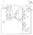
- the air supply device 60 of the present embodiment shown in FIG. 5 includes a liquid supply pipe line 80, a liquid introduction unit 81, and a check valve 67.
- the liquid supply line 80 and the liquid introduction section 81 introduce the liquid into the section between the on-off valve 64 and the atmosphere release valve 65 of the air supply line 63.
- the liquid supply line 80 is connected to a section between the on-off valve 64 of the air supply line 63 and the air release valve 65.
- the liquid introduction unit 81 introduces the liquid into the liquid supply line 80.
- the type of liquid introduced by the liquid introduction unit 81 into the liquid supply line 80 is not particularly limited.
- the liquid introduced by the liquid introduction unit 81 into the liquid supply line 80 may be water, a cleaning liquid, a disinfectant liquid, or alcohol.
- the liquid introduction unit 81 introduces the liquid stored in the treatment tank 2 into the liquid supply line 80.
- the endoscope reprocessor 1 has a configuration in which liquid water, a cleaning liquid, and a disinfecting liquid are introduced into the treatment tank 2.
- one end 80a which is the first end of the liquid supply line 80, is connected to a section between the on-off valve 64 and the atmosphere release valve 65 of the air supply line 63. Further, the other end 80b, which is the second end of the liquid feeding pipe line 80, is connected to the processing tank 2.
- the liquid introduction unit 81 includes a pump provided in the liquid supply line 80.
- the liquid introduction unit 81 is electrically connected to the control unit 69, and the operation of the liquid introduction unit 81 is controlled by the control unit 69. By driving the liquid introduction unit 81, the liquid in the processing tank 2 is introduced into the air supply line 63 via the liquid supply line 80.
- the liquid introduction unit 81 may have a form in which the liquid stored in a container different from the treatment tank is introduced into the air supply pipe line 63.
- the check valve 67 is arranged in the section between the connection portion 63d of the air supply line 63 with the liquid supply line 80 and the air release valve 65.
- the check valve 67 allows the flow of fluid in the air supply line 63 from the air release valve 65 toward the connection portion 63d with the liquid supply line 80, and regulates the flow of fluid in the opposite direction.
- the check valve 67 prevents the liquid introduced into the air supply line 63 via the liquid supply line 80 from flowing into the release valve 65 and the presser connection portion 62. That is, since the check valve 67 is provided, the liquid introduced into the air supply pipe line 63 via the liquid supply pipe line 80 can be used as an endoscope connection portion if the on-off valve 64 is in the open state. It flows into 61.
- FIG. 6 is a flowchart of the air supply process of the present embodiment.
- the air supply process of the present embodiment shown in FIG. 6 is different from the first embodiment in that steps S200 to S230 are executed before step S300.
- step II'of connecting the endoscope conduit 120 to the endoscope connection portion 61 is carried out by the operation of the user.
- step S200 the control unit 69 opens the on-off valve 64.
- step S210 the control unit 69 starts driving the liquid introduction unit 81, and starts introducing the liquid into the air supply line 63.
- step S210 the liquid is stored in the processing tank 2.
- step S210 the liquid in the processing tank 2 is introduced into the endoscope pipe line 120 via the liquid supply pipe line 80, the air supply pipe line 63, and the endoscope connection portion 61.
- step S220 the control unit 69 waits for a predetermined time. While waiting in step S220, the inside of the endoscope line 120 is filled with the liquid.
- step S230 the control unit 69 stops driving the liquid introduction unit 81, and stops the introduction of the liquid into the air supply line 63.
- control unit 69 executes steps S300 and subsequent steps in the same manner as in the first embodiment.
- control unit 69 opens the on-off valve 64 and drives the liquid introduction unit 81 as shown in steps S200 to S230. Step III'to fill the endoscopic tube 120 with liquid is performed.
- the air supply device 60 and its control method of the present embodiment described above describe a gas in which the pressure in the first section 63c is within a predetermined reference range in a state where the endoscope line 120 is filled with a liquid.
- a mixed phase flow gas-liquid two-phase flow in which a liquid and a gas are mixed can be generated in the endoscope line 120.
- the gas-liquid two-phase flow has a higher effect of peeling off the deposits on the wall surface as compared with the case where only gas or only liquid is flowed into the endoscope line 120. Therefore, the endoscope reprocessor 1 provided with the air supply device 60 of the present embodiment can exert high cleaning power in the endoscope conduit 120.
- FIG. 7 is a flowchart of the air supply process of the present embodiment.
- the air supply process of the present embodiment shown in FIG. 7 is different from the first embodiment in that steps S341 and S342 are executed between steps S340 and S350.
- step S300 the control unit 69 closes the on-off valve 64.
- step S310 the control unit 69 reads out the adjustment state of the atmosphere release valve 65 stored in the storage unit 69a, and sets the adjustment state in which the atmosphere release valve 65 is read out.
- step S320 the control unit 69 starts the operation of the compressor 70, and starts introducing the gas from the compressor 70 into the first section 63c of the air supply line 63.
- the execution of steps S300, S310 and S320 may be performed in a different order or at the same time.
- step S330 the control unit 69 waits for a predetermined time. While waiting in step S330, the internal pressure of the first section 63c of the air supply line 63 becomes within the reference range. In step S330, the control unit 69 may end the standby after confirming by the sensor 66 that the internal pressure of the first section 63c is within the reference range.
- step S340 the control unit 69 opens the on-off valve 64.
- the on-off valve 64 is opened, the gas in the first section 63c of the air supply line 63 is led out from the endoscope connection portion 61. That is, by executing step S340, the delivery of gas from the air supply device 60 into the endoscope line 120 begins.
- the compressor 70 is in the operating state, and the introduction of gas from the compressor 70 into the first section 63c of the air supply line 63 continues.
- step S341 the control unit 69 waits for a predetermined time. Then, in step S342, the control unit 69 reduces the amount of air release of the air release valve 65. In step S342, the control unit 69 may close the air release valve 65 and set the air release amount to zero.
- step S350 the control unit 69 waits for a predetermined time.
- the standby time in step S350 is the time for continuing the gas delivery into the endoscope line 120 in the regeneration process.
- the flow velocity of the gas flowing in the endoscope line 120 at the time of executing step S350 is reduced as compared with the first embodiment by reducing the amount of gas released to the atmosphere by executing step S342. Can be enhanced.
- step S370 the control unit 69 stops the operation of the compressor 70 and stops the introduction of gas from the compressor 70 into the air supply pipe line 63.
- step S350 by skipping step S360 and executing step S370, the delivery of gas from the air supply device 60 into the endoscope line 120 may be stopped.
- control unit 69 maintains the introduction of gas from the compressor 70 into the air supply line 63 after step IV, as shown in steps S341 and S342.
- step V for reducing the amount of air release of the air release valve 65 is executed.
- the air supply device 60 of the present embodiment and the control method thereof described above can make the flow velocity of the gas flowing in the endoscope line 120 higher than that of the first embodiment, and the endoscopic line 120 It is possible to quickly remove droplets from the inside.
- steps S341 and S342 of the present embodiment may be executed after step S340 of the air supply process of the second embodiment shown in FIG.
- the flow velocity of the gas-liquid two-phase flow in the endoscopic conduit 120 can be increased, so that the washing is higher. Get power.
- the air supply device 60 of the present embodiment shown in FIG. 8 includes a second on-off valve 68.
- the second on-off valve 68 is arranged in a section between the check valve 67 of the air supply line 63 and the air release valve 65.
- the second on-off valve 68 is electrically connected to the control unit 69, and the operation of the second on-off valve 68 is controlled by the control unit 69.
- the sensor 66 of the present embodiment is arranged in a section between the second on-off valve 68 and the other end 63b of the air supply pipe line 63.
- the air supply device 60 of the present embodiment replaces the on-off valve 64 during the execution of step III'in which the inside of the endoscope line 120 shown in steps S200 to S230 is filled with a liquid in the air supply process shown in FIG.
- the second on-off valve 68 can be closed, and the execution of the steps shown in steps S310 to S330 can be started.
- the on-off valve 64 and the second on-off valve 68 are opened.
- the air supply device 60 of the present embodiment can execute the air supply process in a shorter time.
- the compressor 70 is included in the endoscope reprocessor 1, and the operation of the compressor 70 is controlled by the control unit 69.
- the compressor 70 is the endoscope reprocessor 1. It may be arranged outside.
- the compressor 70 is arranged outside.
- the compressor 70 of the present embodiment continues to supply gas at a predetermined pressure to the endoscope reprocessor 1.
- the air supply device 60 of the present embodiment includes a gas supply valve 62a at the compressor connection portion 62.
- the gas supply valve 62a is electrically connected to the control unit 69, and the operation of the gas supply valve 62a is controlled by the control unit 69.
- the control unit 69 of the present embodiment switches the gas supply valve 62a from the closed state to the open state when starting the introduction of the gas from the compressor 70 into the first section 63c of the air supply line 63. Further, the control unit 69 switches the gas supply valve 62a from the open state to the closed state when the introduction of the gas from the compressor 70 into the first section 63c of the air supply line 63 is stopped.
- step S110 the control unit 69 opens the gas supply valve 62a. Further, in step S150, the control unit 69 closes the gas supply valve 62a. In the air supply process shown in FIG. 4, in step S320, the control unit 69 opens the gas supply valve 62a. Further, in step S370, the control unit 69 closes the gas supply valve 62a.
- the air supply device 60 of the present embodiment is different from the first embodiment only in the configuration and control thereof for introducing gas from the compressor 70 into the air supply pipe line 63, and the other configurations and controls are the first. It is the same as the embodiment. Therefore, the air supply device 60 of the present embodiment and the control method thereof send the gas discharged from the compressor 70 into the endoscope line 120 at a pressure within a predetermined range, as in the first embodiment. be able to.
- the air supply device 60 of the present embodiment may include a liquid supply pipe line 80, a liquid introduction unit 81, and a check valve 67 as in the second embodiment.
- the air supply device 60 of the present embodiment and the control method thereof can generate a gas-liquid two-phase flow in the endoscope line 120.
- the air supply device 60 of the present embodiment and the control method thereof may execute the air supply process shown in FIG. 7 of the third embodiment.
- the air supply device 60 of the present embodiment and the control method thereof can increase the flow velocity of the gas flowing in the endoscope line 120.
- FIG. 10 is a perspective view of the holding net 90 included in the endoscope reprocessor 1 of the present embodiment.
- the holding net 90 shown in FIG. 10 is a device that holds a tubular medical device 200 such as a dilator in the processing tank 2.
- FIG. 10 is a view of the holding net 90 arranged in the processing tank 2 as viewed from diagonally above.
- the holding net 90 includes a main body portion 91, a plurality of leg portions 92, and a plurality of regulating portions 93.
- the main body 91 is a net-like portion having a substantially circular outer peripheral shape.
- the main body 91 is substantially horizontal in the processing tank 2.
- the leg portion 92 extends downward from the main body portion 91. When the legs 92 come into contact with the bottom surface of the processing tank 2, the main body 91 is separated upward from the bottom surface of the processing tank 2.
- the plurality of regulation portions 93 are columnar members extending upward from the outer edge of the main body portion 91. That is, the plurality of regulation units 93 are arranged in substantially the same circumference.
- the plurality of regulating portions 93 hold the shape of the tubular medical device 200 placed above the main body portion 91 in an arc shape. In FIG. 10, the outer shape of the tubular medical device 200 is shown by a chain double-dashed line.
- the arrangement of the plurality of regulating units 93 is different from that of the holding net for the endoscope that holds the endoscope in the processing tank 2 of the endoscope reprocessor 1.
- a tubular medical device 200 such as a dilator has a larger outer diameter than an endoscope insertion portion or a cable.
- the holding net 90 of the present embodiment has a smaller number of regulating portions 93 than the holding net for an endoscope so that it can hold a tubular medical instrument 200 having a large diameter.
- the holding net 90 of the present embodiment is provided with one or more identification labels 94 in order to facilitate identification from the holding net for the endoscope.
- the identification label 94 is fixed to the outer periphery of the regulation unit 93.
- the tubular medical device 200 can be regenerated by the endoscope reprocessor 1.
Landscapes
- Health & Medical Sciences (AREA)
- Life Sciences & Earth Sciences (AREA)
- Surgery (AREA)
- Heart & Thoracic Surgery (AREA)
- Public Health (AREA)
- Engineering & Computer Science (AREA)
- Biomedical Technology (AREA)
- Veterinary Medicine (AREA)
- Animal Behavior & Ethology (AREA)
- General Health & Medical Sciences (AREA)
- Biophysics (AREA)
- Physics & Mathematics (AREA)
- Nuclear Medicine, Radiotherapy & Molecular Imaging (AREA)
- Optics & Photonics (AREA)
- Pathology (AREA)
- Radiology & Medical Imaging (AREA)
- Medical Informatics (AREA)
- Molecular Biology (AREA)
- Anesthesiology (AREA)
- Hematology (AREA)
- Pulmonology (AREA)
- Endoscopes (AREA)
Abstract
L'invention concerne un dispositif d'alimentation en gaz comprenant : une partie de raccordement d'endoscope raccordée à un canal d'endoscope ; une partie de raccordement de compresseur raccordée à un compresseur pour faire s'écouler le gaz ; un canal d'alimentation en gaz ayant une extrémité raccordée à la partie de raccordement d'endoscope et l'autre extrémité raccordée à la partie de raccordement de compresseur ; une soupape marche-arrêt disposée dans le canal d'alimentation en gaz ; une soupape de libération dans l'atmosphère qui est raccordée entre l'autre extrémité et la soupape marche/arrêt dans le canal d'alimentation en gaz et qui permet le réglage de la quantité de gaz libérée dans l'atmosphère à partir de l'intérieur du canal d'alimentation en gaz ; un capteur qui détecte la pression interne du canal d'alimentation en gaz ; et une unité de commande raccordée à la soupape marche/arrêt, à la soupape de libération dans l'atmosphère et au capteur.
Priority Applications (3)
| Application Number | Priority Date | Filing Date | Title |
|---|---|---|---|
| JP2021508648A JP7090209B2 (ja) | 2019-03-28 | 2019-03-28 | 送気装置の制御方法および送気装置 |
| PCT/JP2019/013826 WO2020194725A1 (fr) | 2019-03-28 | 2019-03-28 | Procédé de commande de dispositif d'alimentation en gaz et dispositif d'alimentation en gaz |
| US17/475,652 US20220000347A1 (en) | 2019-03-28 | 2021-09-15 | Method for controlling air feeding device and air feeding device |
Applications Claiming Priority (1)
| Application Number | Priority Date | Filing Date | Title |
|---|---|---|---|
| PCT/JP2019/013826 WO2020194725A1 (fr) | 2019-03-28 | 2019-03-28 | Procédé de commande de dispositif d'alimentation en gaz et dispositif d'alimentation en gaz |
Related Child Applications (1)
| Application Number | Title | Priority Date | Filing Date |
|---|---|---|---|
| US17/475,652 Continuation US20220000347A1 (en) | 2019-03-28 | 2021-09-15 | Method for controlling air feeding device and air feeding device |
Publications (1)
| Publication Number | Publication Date |
|---|---|
| WO2020194725A1 true WO2020194725A1 (fr) | 2020-10-01 |
Family
ID=72611229
Family Applications (1)
| Application Number | Title | Priority Date | Filing Date |
|---|---|---|---|
| PCT/JP2019/013826 WO2020194725A1 (fr) | 2019-03-28 | 2019-03-28 | Procédé de commande de dispositif d'alimentation en gaz et dispositif d'alimentation en gaz |
Country Status (3)
| Country | Link |
|---|---|
| US (1) | US20220000347A1 (fr) |
| JP (1) | JP7090209B2 (fr) |
| WO (1) | WO2020194725A1 (fr) |
Citations (2)
| Publication number | Priority date | Publication date | Assignee | Title |
|---|---|---|---|---|
| JP2014079369A (ja) * | 2012-10-16 | 2014-05-08 | Olympus Corp | 送気装置 |
| WO2017026138A1 (fr) * | 2015-08-11 | 2017-02-16 | オリンパス株式会社 | Dispositif de retraitement d'endoscope et procédé de détection de défaillance |
-
2019
- 2019-03-28 WO PCT/JP2019/013826 patent/WO2020194725A1/fr active Application Filing
- 2019-03-28 JP JP2021508648A patent/JP7090209B2/ja active Active
-
2021
- 2021-09-15 US US17/475,652 patent/US20220000347A1/en active Pending
Patent Citations (2)
| Publication number | Priority date | Publication date | Assignee | Title |
|---|---|---|---|---|
| JP2014079369A (ja) * | 2012-10-16 | 2014-05-08 | Olympus Corp | 送気装置 |
| WO2017026138A1 (fr) * | 2015-08-11 | 2017-02-16 | オリンパス株式会社 | Dispositif de retraitement d'endoscope et procédé de détection de défaillance |
Also Published As
| Publication number | Publication date |
|---|---|
| JPWO2020194725A1 (ja) | 2021-11-04 |
| US20220000347A1 (en) | 2022-01-06 |
| JP7090209B2 (ja) | 2022-06-23 |
Similar Documents
| Publication | Publication Date | Title |
|---|---|---|
| US6858181B2 (en) | Method for cleaning and sterilizing medical equipment after use | |
| KR101177868B1 (ko) | 핸드피스 소독 멸균장치 | |
| JP2009142324A (ja) | 内視鏡洗浄消毒装置 | |
| JP6827149B2 (ja) | 洗浄システム、洗浄ユニット及び洗浄方法 | |
| KR20090112566A (ko) | 내시경 세정 소독 장치 및 내시경 세정 소독 장치의 소독액 조제 방법 | |
| JP7090209B2 (ja) | 送気装置の制御方法および送気装置 | |
| WO2016194456A1 (fr) | Retraitement d'endoscope | |
| JP5086784B2 (ja) | 内視鏡洗浄消毒装置 | |
| US20130019910A1 (en) | Endoscopic component cleaning system and method | |
| US10194790B2 (en) | Endoscope reprocessor, endoscope cleaning tube, and endoscope reprocessing unit | |
| JP6599757B2 (ja) | 内視鏡リプロセッサ | |
| JP2006191979A (ja) | 内視鏡洗浄消毒装置 | |
| US11540708B2 (en) | Endoscope reprocessing method and endoscope reprocessor | |
| JP2009225811A (ja) | 内視鏡洗浄消毒装置 | |
| JP4789561B2 (ja) | 内視鏡用洗浄消毒装置 | |
| JP6010273B1 (ja) | 内視鏡リプロセッサ | |
| KR100839649B1 (ko) | 의료기기 세척기 | |
| JP2018000438A (ja) | 内視鏡リプロセッサ | |
| CN116851343B (zh) | 一种消化内科临床器械清洗器 | |
| JP2009225813A (ja) | 内視鏡洗浄消毒装置 | |
| JP6854609B2 (ja) | 内視鏡リプロセッサ | |
| JP6465331B1 (ja) | 内視鏡リプロセッサの制御方法および内視鏡リプロセッサ | |
| WO2018179572A1 (fr) | Procédé de retraitement d'endoscope et dispositif de retraitement d'endoscope | |
| JP6099857B1 (ja) | 内視鏡リプロセッサ、内視鏡洗浄チューブ及び内視鏡リプロセスセット | |
| JP2009225812A (ja) | 内視鏡洗浄消毒装置 |
Legal Events
| Date | Code | Title | Description |
|---|---|---|---|
| 121 | Ep: the epo has been informed by wipo that ep was designated in this application |
Ref document number: 19921036 Country of ref document: EP Kind code of ref document: A1 |
|
| ENP | Entry into the national phase |
Ref document number: 2021508648 Country of ref document: JP Kind code of ref document: A |
|
| NENP | Non-entry into the national phase |
Ref country code: DE |
|
| 122 | Ep: pct application non-entry in european phase |
Ref document number: 19921036 Country of ref document: EP Kind code of ref document: A1 |