WO2020194722A1 - 表示装置の取り付け構造、表示装置の取り付け方法、及び、表示装置の結露防止方法 - Google Patents
表示装置の取り付け構造、表示装置の取り付け方法、及び、表示装置の結露防止方法 Download PDFInfo
- Publication number
- WO2020194722A1 WO2020194722A1 PCT/JP2019/013821 JP2019013821W WO2020194722A1 WO 2020194722 A1 WO2020194722 A1 WO 2020194722A1 JP 2019013821 W JP2019013821 W JP 2019013821W WO 2020194722 A1 WO2020194722 A1 WO 2020194722A1
- Authority
- WO
- WIPO (PCT)
- Prior art keywords
- display device
- film body
- windshield
- display screen
- mounting structure
- Prior art date
- Legal status (The legal status is an assumption and is not a legal conclusion. Google has not performed a legal analysis and makes no representation as to the accuracy of the status listed.)
- Ceased
Links
Images







Classifications
-
- B—PERFORMING OPERATIONS; TRANSPORTING
- B60—VEHICLES IN GENERAL
- B60K—ARRANGEMENT OR MOUNTING OF PROPULSION UNITS OR OF TRANSMISSIONS IN VEHICLES; ARRANGEMENT OR MOUNTING OF PLURAL DIVERSE PRIME-MOVERS IN VEHICLES; AUXILIARY DRIVES FOR VEHICLES; INSTRUMENTATION OR DASHBOARDS FOR VEHICLES; ARRANGEMENTS IN CONNECTION WITH COOLING, AIR INTAKE, GAS EXHAUST OR FUEL SUPPLY OF PROPULSION UNITS IN VEHICLES
- B60K35/00—Instruments specially adapted for vehicles; Arrangement of instruments in or on vehicles
- B60K35/20—Output arrangements, i.e. from vehicle to user, associated with vehicle functions or specially adapted therefor
- B60K35/21—Output arrangements, i.e. from vehicle to user, associated with vehicle functions or specially adapted therefor using visual output, e.g. blinking lights or matrix displays
- B60K35/22—Display screens
-
- B—PERFORMING OPERATIONS; TRANSPORTING
- B60—VEHICLES IN GENERAL
- B60K—ARRANGEMENT OR MOUNTING OF PROPULSION UNITS OR OF TRANSMISSIONS IN VEHICLES; ARRANGEMENT OR MOUNTING OF PLURAL DIVERSE PRIME-MOVERS IN VEHICLES; AUXILIARY DRIVES FOR VEHICLES; INSTRUMENTATION OR DASHBOARDS FOR VEHICLES; ARRANGEMENTS IN CONNECTION WITH COOLING, AIR INTAKE, GAS EXHAUST OR FUEL SUPPLY OF PROPULSION UNITS IN VEHICLES
- B60K35/00—Instruments specially adapted for vehicles; Arrangement of instruments in or on vehicles
- B60K35/20—Output arrangements, i.e. from vehicle to user, associated with vehicle functions or specially adapted therefor
- B60K35/21—Output arrangements, i.e. from vehicle to user, associated with vehicle functions or specially adapted therefor using visual output, e.g. blinking lights or matrix displays
- B60K35/23—Head-up displays [HUD]
- B60K35/231—Head-up displays [HUD] characterised by their arrangement or structure for integration into vehicles
-
- B—PERFORMING OPERATIONS; TRANSPORTING
- B60—VEHICLES IN GENERAL
- B60K—ARRANGEMENT OR MOUNTING OF PROPULSION UNITS OR OF TRANSMISSIONS IN VEHICLES; ARRANGEMENT OR MOUNTING OF PLURAL DIVERSE PRIME-MOVERS IN VEHICLES; AUXILIARY DRIVES FOR VEHICLES; INSTRUMENTATION OR DASHBOARDS FOR VEHICLES; ARRANGEMENTS IN CONNECTION WITH COOLING, AIR INTAKE, GAS EXHAUST OR FUEL SUPPLY OF PROPULSION UNITS IN VEHICLES
- B60K35/00—Instruments specially adapted for vehicles; Arrangement of instruments in or on vehicles
- B60K35/50—Instruments characterised by their means of attachment to or integration in the vehicle
-
- B—PERFORMING OPERATIONS; TRANSPORTING
- B60—VEHICLES IN GENERAL
- B60K—ARRANGEMENT OR MOUNTING OF PROPULSION UNITS OR OF TRANSMISSIONS IN VEHICLES; ARRANGEMENT OR MOUNTING OF PLURAL DIVERSE PRIME-MOVERS IN VEHICLES; AUXILIARY DRIVES FOR VEHICLES; INSTRUMENTATION OR DASHBOARDS FOR VEHICLES; ARRANGEMENTS IN CONNECTION WITH COOLING, AIR INTAKE, GAS EXHAUST OR FUEL SUPPLY OF PROPULSION UNITS IN VEHICLES
- B60K35/00—Instruments specially adapted for vehicles; Arrangement of instruments in or on vehicles
- B60K35/60—Instruments characterised by their location or relative disposition in or on vehicles
-
- B—PERFORMING OPERATIONS; TRANSPORTING
- B60—VEHICLES IN GENERAL
- B60K—ARRANGEMENT OR MOUNTING OF PROPULSION UNITS OR OF TRANSMISSIONS IN VEHICLES; ARRANGEMENT OR MOUNTING OF PLURAL DIVERSE PRIME-MOVERS IN VEHICLES; AUXILIARY DRIVES FOR VEHICLES; INSTRUMENTATION OR DASHBOARDS FOR VEHICLES; ARRANGEMENTS IN CONNECTION WITH COOLING, AIR INTAKE, GAS EXHAUST OR FUEL SUPPLY OF PROPULSION UNITS IN VEHICLES
- B60K35/00—Instruments specially adapted for vehicles; Arrangement of instruments in or on vehicles
- B60K35/80—Arrangements for controlling instruments
-
- B—PERFORMING OPERATIONS; TRANSPORTING
- B60—VEHICLES IN GENERAL
- B60R—VEHICLES, VEHICLE FITTINGS, OR VEHICLE PARTS, NOT OTHERWISE PROVIDED FOR
- B60R11/00—Arrangements for holding or mounting articles, not otherwise provided for
- B60R11/02—Arrangements for holding or mounting articles, not otherwise provided for for radio sets, television sets, telephones, or the like; Arrangement of controls thereof
-
- H—ELECTRICITY
- H05—ELECTRIC TECHNIQUES NOT OTHERWISE PROVIDED FOR
- H05B—ELECTRIC HEATING; ELECTRIC LIGHT SOURCES NOT OTHERWISE PROVIDED FOR; CIRCUIT ARRANGEMENTS FOR ELECTRIC LIGHT SOURCES, IN GENERAL
- H05B3/00—Ohmic-resistance heating
- H05B3/84—Heating arrangements specially adapted for transparent or reflecting areas, e.g. for demisting or de-icing windows, mirrors or vehicle windshields
- H05B3/86—Heating arrangements specially adapted for transparent or reflecting areas, e.g. for demisting or de-icing windows, mirrors or vehicle windshields the heating conductors being embedded in the transparent or reflecting material
-
- B—PERFORMING OPERATIONS; TRANSPORTING
- B60—VEHICLES IN GENERAL
- B60S—SERVICING, CLEANING, REPAIRING, SUPPORTING, LIFTING, OR MANOEUVRING OF VEHICLES, NOT OTHERWISE PROVIDED FOR
- B60S1/00—Cleaning of vehicles
- B60S1/02—Cleaning windscreens, windows or optical devices
Definitions
- the present invention relates to a display device mounting structure, a display device mounting method, and a display device dew condensation prevention method.
- Patent Document 1 discloses a transmissive liquid crystal display panel integrally incorporated with an automobile windshield. This transmissive liquid crystal display panel is provided above the windshield in front of the driver's seat.
- the display device is used in a temperature and humidity environment that changes more widely than before due to the diversification of the place where it is installed or the place where it is carried.
- the temperature and humidity around the display device can change independently with time.
- the display device is required to be able to promptly and accurately visually recognize the displayed image to the user even under such a situation where the physical environment changes widely and variously.
- the present disclosure provides a display device mounting structure, a display device mounting method, and a dew condensation prevention method for the display device, which can prevent or eliminate the deterioration of the visibility of the displayed image due to changes in the surrounding environment. The purpose.
- the mounting structure of the display device is provided on one surface consisting of a display device having a display screen for displaying an image and a predetermined flat surface or curved surface facing the interior of the vehicle, and can pass current.
- the display device includes the film body, and the display device is directed through the film body so that the display screen can be heated by the heat generated based on the energization of the film body and the display screen is directed to the room. It is attached to the one side.
- a film body capable of passing current is provided on a predetermined plane or curved surface facing the interior of the vehicle, and the display device having a display screen is attached to the film body.
- the display screen is attached to the predetermined plane or curved surface toward the room and via the film body so that the display screen is warmed by the heat generated based on the energization of the above.
- heat is generated in the film body by passing a current through a film body provided on a predetermined flat surface or curved surface facing the interior of the vehicle, and the film body is described. This includes preventing the adhesion of water droplets to the display screen by warming the display screen of the display device attached to the predetermined flat surface or curved surface via the film body using the heat.
- FIG. 1 shows an example of the display device attached to the windshield of an automobile which has the attachment structure of the display device of Embodiment 1 of this disclosure.
- It is sectional drawing which shows an example of the attachment structure of the display device of Embodiment 1, corresponding to the cross section in line II-II of FIG.
- It is a side view which shows the display device which has the attachment structure of Embodiment 1 together with an automobile.
- It is a front view which shows an example of the film body in the attachment structure of Embodiment 1.
- FIG. It is a front view which shows an example of the electrode of the film body in the attachment structure of Embodiment 1.
- FIG. It is a front view which shows another example of the membrane body in the attachment structure of Embodiment 1.
- FIG. It is a front view which shows another example of the membrane body in the attachment structure of Embodiment 1.
- FIG. It is a front view which shows another example of the membrane body in the attachment structure of Embodiment 1.
- FIG. It is a front view which shows another example of the membrane body in the attachment structure of Embodiment 1.
- FIG. It is a block diagram which shows each element in the mounting structure of Embodiment 1.
- FIG. It is a figure which shows the other arrangement example of the display device in the mounting structure of Embodiment 1.
- FIG. It is a front view which shows the example which the windshield is provided in the attachment structure of Embodiment 1.
- 9A is a cross-sectional view taken along the line IXB-IXB of FIG. 9A.
- It is sectional drawing which shows an example of the attachment structure of the display device of Embodiment 2 of this disclosure.
- It is a figure which shows an example of the attachment method of the display device of another embodiment of this disclosure.
- the present inventor has found a problem that the visibility of the display screen may be lowered in the actual use of the display device even under the physical environment within the range assumed at the time of design.
- a vehicle such as an automobile
- the temperature of the wall that separates the inside of the vehicle from the outside of the vehicle, such as a window glass decreases, and dew condensation may occur on the surface thereof.
- dew condensation may occur as the humidity rises.
- a liquid crystal display panel is provided on the windshield of an automobile like the liquid crystal display panel of Patent Document 1 described above, dew condensation occurs on the display screen and the visibility thereof deteriorates.
- the safety confirmation in front of the vehicle may be hindered.
- the liquid crystal display panel is provided to display a scene behind or to the side of the automobile, safety confirmation in each direction may be hindered.
- Automobiles are generally equipped with a defroster (defroster) that eliminates dew condensation by blowing hot air on the windshield from below.
- a defroster defroster
- the windshield is fixed to the vehicle body so that its upper side is inclined to the rear of the vehicle.
- the present inventor further describes that the display device provided on the upper part of the windshield has a problem of eye focus adjustment based on the proximity of the display device to the human eye in the vehicle interior, as will be described in detail later. I found it to be inherent. Therefore, from these viewpoints, when the display device is provided in the interior of the vehicle, particularly in the windshield of the automobile, it is considered that there is a benefit in providing the display device in the lower part of the windshield.
- the hot air of the defroster provided to eliminate the dew condensation on the entire windshield is directly applied to the display device, there is a concern that the heat will accelerate the deterioration of the display device. Further, it may be difficult to evenly apply hot air to the display device. In such a case, there is a concern that the hot air hit by the non-uniformity causes the non-uniformity of the temperature rise of the display device, and as a result, the progress of deterioration is locally promoted. In particular, since the heat resistance of the organic EL element contained in the organic EL display device is lower than that of the liquid crystal or the like, there is a concern that the organic EL element may be deteriorated by the hot air repeatedly blown in the organic EL display device.
- the display device mounted on the vehicle can prevent or eliminate dew condensation on the display screen without relying on the action of the defroster and regardless of the mounting position.
- the present inventor has found new display device mounting structures, display device mounting methods, dew condensation prevention methods for display devices, and technical matters related thereto.
- a display device mounting structure, a display device mounting method, and a dew condensation prevention method of the display device according to the embodiment of the present invention will be described.
- the materials, shapes, and relative positional relationships of the components in the embodiments described below are merely examples.
- the mounting structure of the display device, the mounting method of the display device, and the dew condensation prevention method of the display device of each embodiment are not limitedly interpreted by these. Further, in the following, each embodiment will be described by taking as an example a case where a display device is attached to the windshield of an ordinary passenger car.
- the display device mounting structure, the display device mounting method, and the dew condensation prevention method of the display device of the embodiment can be adopted not only in ordinary automobiles but also in various vehicles such as buses, trucks, and trains.
- FIG. 1 shows the display device 1 which is an example of the display device having the display device mounting structure of the first embodiment of the present disclosure together with the inside of the vehicle interior R.
- the display device 1 is attached to the windshield 3 of an automobile.
- FIG. 2 shows a cross-sectional view of an example of the mounting structure of the display device of the first embodiment, which corresponds to the cross-sectional view taken along the line II-II of FIG.
- the mounting structure of the display device of the present embodiment is composed of a display device 1 having a display screen 11 for displaying an image and a predetermined flat surface or curved surface facing the interior of the vehicle. It includes the provided membrane body 2.
- the film body 2 is provided on one side 3a of the windshield 3 of the automobile facing the passenger compartment R.
- the display device 1 is attached to one side 3a of the windshield 3 with the display screen 11 facing the inside of the vehicle interior R and via the film body 2.
- the film body 2 is formed so that an electric current that generates Joule heat that can heat the display screen 11 can be passed through the film body 2.
- the display device 1 since the display device 1 is attached via the film body 2 which can generate heat by energization in this way, a current is passed through the film body 2 as needed, and the display screen is displayed by energizing the film body 2. 11 is warmed.
- the display device 1 is attached to one surface 3a via the film body 2 so that the display screen 11 is warmed by the heat generated based on the energization of the film body 2, so that the temperature of the display screen 11 can be adjusted. It can be higher than the ambient temperature and the temperature of the windshield 3. Further, even when the ambient temperature of the display device 1 is low and the saturated water vapor amount is small, it is possible to prevent the occurrence of dew condensation on the display screen 11. Further, when dew condensation has occurred, the dew condensation can be eliminated by passing an electric current through the film body 2.
- dew condensation on the display screen 11 can be prevented or eliminated by passing an electric current through the film body 2. .. That is, it is possible to prevent or eliminate dew condensation on the display screen 11 without relying on the action of the defroster, and therefore, it is possible to prevent a decrease in visibility due to such dew condensation or restore visibility.
- restrictions on the mounting position of the display device 1 can be reduced, and the degree of freedom thereof can be increased. As a result, it is considered that it can contribute to the improvement of vehicle operation safety and vehicle convenience.
- the display device 1 in the example of FIG. 1 is a lower region of the windshield 3 and is attached to a central portion in the vehicle width direction.
- a defroster (not shown) outlet B is provided on the upper surface of the dashboard D, which is close to the lower part of the display device 1.
- dew condensation on the display screen 11 can be prevented or eliminated without using the hot air of the defroster.
- the display device 1 is held on one surface 3a of the windshield 3 by using the holding member 4. That is, the holding member 4 is fixed to one surface 3a of the windshield 3 using an arbitrary adhesive (not shown), and the movement of the display device 1 on the one surface 3a and the separation of the display device 1 from the one surface 3a are the holding members. Limited by 4.
- the holding member 4 has a square frame-shaped front shape, and specifically, has a flat U-shaped front shape lacking one side of the square front shape. Each side of the holding member 4 has an L-shaped cross section so as to abut the side surface of the display device 1 and the front surface of the display device 1 having the display screen 11.
- the display device 1 having a rectangular front shape is fixed to one surface 3a of the windshield 3 by being held by a holding member 4 at edges along three sides of the rectangular shape.
- the holding member 4 is formed of, for example, a synthetic resin such as a silicone resin or an epoxy resin.
- Examples of the display device 1 include an organic EL display panel, a liquid crystal display panel, and a micro LED display panel, which may have a thin form.
- the organic EL display panel, the liquid crystal display panel, and the micro LED display panel include a plurality of pixels (not shown) arranged in a matrix and a substrate having a thin film transistor (TFT) for driving each of the plurality of pixels on one surface. May include.
- the display screen 11 is composed of a plurality of pixels.
- a window glass such as a windshield 3
- an organic EL display panel that is easily formed to have translucency as compared with a liquid crystal display panel or a micro LED display panel is preferable as the display device 1. ..
- the display device 1 may be formed by using a material having translucency, and in that case, it is particularly preferable that the film body 2 is also formed by using a material having translucency.
- the display device 1 and the film body 2 have such translucency, in the example of FIG. 1, a person in the vehicle interior R can see the front view through the display device 1.
- the display device 1 having translucency includes, for example, a transparent polyimide resin film, a conductive material having translucency such as indium tin oxide (ITO), and It can be formed by using a transparent amorphous oxide semiconductor such as an oxide composed of indium, gallium, and zinc.
- the holding member 4 is also preferably formed of a highly transparent material such as a silicone resin or an acrylic resin.
- the organic EL display panel, the liquid crystal display panel, and the micro LED display panel are merely examples, and the display device 1 is not limited to the organic EL display panel, the liquid crystal display panel, and the micro LED display panel.
- an image pickup device 9 for capturing a front view through the windshield 3 is provided on the ceiling of the passenger compartment R above the windshield 3.
- the display device 1 displays, for example, an image captured by the image pickup device 9.
- the display device 1 may display an image based on an image signal sent from a navigation system or the like.
- the image pickup device 9 is a digital camera having, for example, a CCD image sensor or a CMOS image sensor.
- the display device 1 is attached to one side 3a of the windshield 3 via the film body 2 with the display screen 11 facing the passenger compartment R.
- the heat generated by the film body 2 due to the energization is conducted through the inside of the display device 1 toward the display screen 11 to warm the display screen 11.
- a power supply path 23 which is a power supply path for passing a current through the film body 2 is formed on one surface 3a of the windshield 3.
- the power supply path 23 is formed by using, for example, a metal such as copper, silver, or aluminum, or an inorganic compound such as ITO or zinc oxide, and is patterned into an appropriate shape.
- One end of the power supply path 23 is connected to the membrane body 2.
- the power supply path 23 is covered with an insulating coating film 25.
- the coating film 25 is formed using any insulating material such as polyvinyl chloride or polyester.
- the holding member 4 is provided with a connection terminal 41 that comes into contact with an input terminal (not shown) of the display device 1 into which an image signal, a control signal, or the like is input.
- the connection terminal 41 is connected to a display control circuit (not shown) such as a timing controller via a wiring provided on one side 3a of the windshield 3 like the power supply path 23.
- the display device 1 of FIG. 2 is provided with a temperature sensor 12.
- the temperature sensor 12 mainly detects the temperature of the display screen 11 which is heated by the heat of the film body 2.
- the temperature sensor 12 can also detect the temperature around the display screen 11 if it has appropriate detection performance.
- the detection result of the temperature sensor 12, that is, the output of the temperature sensor 12 including the temperature information around the display screen 11 and / or the display device 1, is transmitted to either or both of the control unit 7 and the display device 1 described later.
- a control unit 7 for controlling energization of the film body 2 is arranged inside the dashboard D.
- the control unit 7 is represented simply by a simple rectangular block so that its existence is conceptually shown.
- the control unit 7 controls the start and stop of energization of the film body 2 as described later. Therefore, the power supply path 23 is connected to the control unit 7.
- Power is supplied to the control unit 7 and the film body 2 from a power source (not shown).
- the energization of the film body 2 may be controlled by a processing device (not shown) included in the display device 1 including a microcomputer or the like.
- the film body 2 can be provided on one surface of an arbitrary flat surface or curved surface facing the inside of the vehicle interior of the vehicle. Further, the film body 2 can be provided not only in an ordinary passenger car but also in any vehicle including a bus, a truck, a train and the like.
- the "predetermined flat surface or curved surface" on which the film body 2 is provided is not limited to the windshield of an automobile.
- the film body 2 may be provided on the side or rear window of the automobile, or on the window of the driver's seat or the passenger's seat of the train, or may be provided on the surface of any interior material facing the interior of the vehicle.
- FIG. 3 shows a display device 1 having the mounting structure of the first embodiment as viewed from the side of the automobile C together with the automobile C. Further, the display device 1x is shown as a virtual display device provided on the upper part of the windshield 3. In front of the automobile C, an object OB to be visually recognized by the driver M, such as a pedestrian or a preceding vehicle, is shown.
- the upper side is usually tilted toward the rear of the vehicle, that is, toward the passenger compartment. Therefore, the distance between the upper part of the windshield 3 and the driver M is shorter than the distance between the lower part of the windshield 3 and the driver M. Therefore, when the display device 1x is provided on the upper part of the windshield 3, the distance L1 between the display device 1x and the driver M is the distance L2 between the display device 1 provided on the lower part of the windshield 3 and the driver M. Shorter than.
- the driver M looks further ahead than the windshield 3 for many hours while driving, and focuses his eyes on the object OB to be visually recognized, for example, a pedestrian.
- the distance L3 between the object OB to be visually recognized and the driver M is longer than both the distance L1 and the distance L2, but the difference between the distance L2 and the distance L3 is smaller than the difference between the distance L1 and the distance L3. Therefore, the driver M looking at the object OB outside the vehicle can focus faster by focusing on the display device 1 than by focusing on the display device 1x.
- the driver M looking at the display device 1 or the display device 1x provided on the windshield 3 is faster when looking at the display device 1 than when looking at the display device 1x.
- adjusting the focus of the human eye can take more than a second.
- a car traveling at a speed of 60 km / h travels more than 15 m in one second. Therefore, from the viewpoint of safe vehicle operation, it is preferable that the fluctuation of the distance between the object to be focused on while driving (for example, the object OB and the display device 1) and the driver M is as small as possible.
- the display device 1 when the display device 1 is attached to the windshield of an automobile, it is preferably attached to the lower part of the windshield 3 in order to secure an appropriate distance between the display device 1 and the driver M.
- a defroster (not shown) is operated at the time of dew condensation, a high temperature strong wind is blown to the lower part of the windshield 3, but in the present embodiment, the dew condensation on the display screen 11 can be eliminated without using the defroster.
- the display device 1 is attached to the windshield 3 below the center of the automobile C in the vertical direction. In that case, the display device 1 can be moved away from the driver M as compared with the case where the display device 1 is attached to the upper side of the windshield 3.
- the display device 1 may be attached to a region of the windshield 3 within 150 mm from its lower edge. In that case, the display device 1 may be the farthest away from the driver M.
- the display device 1 and the film body 2 do not have transparency, they may satisfy the criteria regarding the transparency of the windshield of the vehicle in the country of use of the vehicle.
- FIG. 4 shows a film body 2 provided on one surface 3a of the windshield 3 in the example of FIG.
- the film body 2 is a thin film body through which an electric current can flow, and is formed by, for example, sputtering or printing.
- the film body 2 can generate Joule heat to the extent that the display screen 11 (see FIG. 2) can be heated by energization. That is, the film body 2 has an appropriate electric resistance Rg through which a current sufficient to heat the display screen 11 can flow.
- the electric resistance Rg required when it is desired to raise the temperature of the display screen 11 by 10 ° C. within 1 minute is illustrated below.
- the specific heat capacity Cp of the display device 1 having a front size of 0.3 m ⁇ 0.15 m is 1.5 J / g ⁇ ° C. (specific heat of the polyimide resin used as a substrate for an organic EL display panel 1. (Assumed to be slightly larger based on 13 J / g ⁇ ° C.) and its mass is 25 g to 30 g, the calorific value Q of the film body 2 is required to be about 400 J to 500 J.
- the appropriate electric resistance Rg Vp 2 ⁇ 60 sec / Q, and therefore, a value of about 10 ⁇ to 100 ⁇ is exemplified. ..
- the amount of heat required to raise the temperature of the water droplet having a specific heat capacity of 4.2 J / g ⁇ ° C. is also required.
- the temperature drops on the screen of the display device 1 of the above size attached to the windshield having a width of 1.5 m and a height of 1 m in a passenger compartment having a volume of 3 m 3.
- the amount of water adhering with the decrease in the amount of saturated water vapor is estimated to be about 0.5 g to 1 g.
- the calorific value Q also includes a calorific value that raises the temperature of this amount of water droplets by 10 ° C.
- a 24V power supply it is possible to obtain the same calorific value Q as when a 12V power supply is used by using the film body 2 which has four times the electric resistance as compared with the case where the 12V power supply is used.
- the current flowing through the film body 2 can be halved as compared with the case of using the 12V power supply.
- a booster circuit 7e such as a booster DC / DC converter may be provided between the power supply and the film body 2. By doing so, the current value can be reduced as described above, and the usable range of the electrical resistance of the film body 2 can be expanded.
- the booster circuit 7e may be used to increase the amount of heat generated per unit time. By doing so, it is possible to shorten the time required to bring a predetermined temperature rise to the display device 1. For example, by using a booster circuit that doubles the voltage without changing the electrical resistance of the film body 2, the time required to obtain a predetermined temperature rise can be reduced to 1/4.
- the feeding path 23 (see FIG. 2) to the membrane body 2 is provided with an insulating coating film 25. Covering with (see FIG. 2) is preferable in order to prevent an unexpected electric shock.
- the film body 2 is formed by using a material capable of forming an appropriate electric resistance Rg as described above. Further, the material of the film body 2 is selected in consideration of the above-mentioned translucency and the goodness of film formation by sputtering or the like when forming the film body 2. Therefore, examples of the material of the film body 2 include ITO and zinc oxide, which have both relatively low conductivity suitable for heat generation and good light transmission. Further, when the film body 2 is formed thinner than the case where the film body 2 is formed by these inorganic compounds, a metal having higher conductivity such as titanium, chromium, rhodium, nickel or aluminum is used as the film body. It may be used as the material of 2.
- the film body 2 can have, for example, an electric conductivity (conductivity) of 0.1 ⁇ 10 6 S / m or more and 7 ⁇ 10 7 S / m or less. Further, when the film body 2 is formed by using ITO, zinc oxide or the like, the film body 2 may have a conductivity of 0.2 ⁇ 10 6 S / m or more and 1 ⁇ 10 6 S / m or less.
- Compounds such as ITO and zinc oxide, and metals such as titanium and chromium have reflection characteristics against infrared rays. Therefore, by forming the film body 2 using these compounds or metals, it is possible to prevent an unintended excessive temperature rise of the display device 1 due to irradiation with sunlight.
- the thickness T that the film body 2 having a predetermined conductivity should have, the length L in the direction parallel to the current flow, and the length (width) W in the direction orthogonal to the current flow are appropriate. Correlate with each other to provide a good electrical resistance Rg.
- the film body 2 formed by sputtering or the like can be formed, for example, within a thickness range of 1 nm or more and 1000 nm or less.
- the film body 2 having such a thickness T has appropriate electrical resistance and mechanical strength, and may have higher transparency.
- the film body 2 is formed to have a thickness of, for example, 2 nm or more and 14 nm or less in order to have transparency. ..
- the film body 2 when the film body 2 is formed using nickel having a conductivity of about 14 ⁇ 10 6 S / m, the film body 2 has a sheet resistance Rs of about 5 ⁇ / sq or more and about 36 ⁇ / sq or less. Can have.
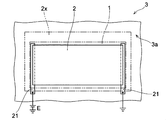
- the film body 2 has a rectangular front shape that is substantially similar to the front shape of the display device 1 indicated by the alternate long and short dash line.
- the film body 2 is formed so as to have an area smaller than the area of the display device 1 in the front view, and the entire surface thereof is covered by the display device 1. Therefore, it is considered that the aesthetic appearance around the display device 1 is not easily spoiled in the vehicle interior.
- the film body 2 may have a larger area than the display device 1, such as the film body 2x drawn by the alternate long and short dash line on the outside of the display device 1 in FIG. 4, and therefore, the display device 1 may have a larger area. It may be formed so that a part is exposed to the outside.
- the film body 2 which can be formed of ITO, titanium or the like may have a higher thermal conductivity than the windshield 3. Therefore, as will be described later, heating of the display screen 11 may be promoted by heating the exposed portion of the film body 2 using a heat source other than the film body 2.
- each of the two opposing short sides of the film body 2 having a rectangular front shape overlaps with the electrode 21.
- a voltage based on the power source E is applied to the film body 2 via the electrode 21, and a current is passed through the film body 2.
- the electrode 21 is preferably made of a material having higher conductivity than the material forming the film body 2.
- the electrode 21 is composed of a conductor film containing aluminum, nickel, or the like.
- the electrode 21 may be connected to the power supply path 23 (see FIG. 2) at any portion thereof, or may be integrally formed with the power supply path 23. Further, the electrode 21 does not necessarily have to be along the short side of the film body 2 as shown in FIG. 4, and may be formed so as to overlap the long side along the long side of the film body 2. Further, the electrode 21 does not have to be in contact with one side over the entire length of one side of the film body 2, and may be in contact with the film body 2 at one or more arbitrary positions on each side of the film body 2.
- each of the two electrodes 21 is arranged as in the example of FIG. 4, it is considered that the power supply path to the film body 2 is short and it is difficult to be noticed.
- the electrodes 21 are provided on the two opposite sides of the film body 2, they may be formed as in the example of FIG.
- one electrode 21a first electrode
- the other electrode 21b second electrode
- the positive electrode of the power source E may be connected to the electrode 21b in the example of FIG.
- FIGS. 6A-6D Other examples of the membrane 2 will be described with reference to FIGS. 6A-6D.
- the electrode 21 shown in FIG. 4 is omitted.
- the membrane body 2a of another example shown in FIG. 6A includes two regions 2a1 and 2a2 electrically separated from each other. That is, the film body 2a of FIG. 6A includes a region 2a1 and a region 2a2 that are separated from each other, and electric power is supplied to each of the regions 2a1 and 2a2.
- the membrane body 2a which is a heating element
- FIG. 6A by separating the membrane body 2a, which is a heating element, into a plurality of regions having an area smaller than that of the membrane body 2a, heat generation in the entire membrane body 2a is generated as compared with the examples of FIGS. 4 and 5. It may be possible to increase the uniformity of the quantity distribution.
- a voltage having a magnitude of 1/2 of the voltage to be applied to the film body 2 in order to obtain the calorific value Q in the examples of FIGS. 4 and 5 is applied to the regions 2a1 and 2a2, respectively.
- the calorific value Q can be obtained.
- the film body 2a is not limited to the example of FIG. 6A, and may include a plurality of regions more than 2.
- the film body 2a may include a plurality of regions separated in a grid pattern. By dividing the film body 2 into n regions having substantially the same electrical resistance and connecting the regions in parallel, the required voltage can be reduced to 1 / n.
- each region can suppress unevenness in the amount of heat generated in each region by applying a voltage corresponding to the electrical resistance to each region. It is preferable to use a separate power supply for the power supply.
- the film body 2b of another example shown in FIG. 6B has a front shape that meanders in a zigzag manner. That is, the film body 2b defines the current path from the current inflow point Ps to the current outflow point Pd by its own shape, and the current path meanders in a zigzag manner.
- the ratio (L / W) of the length L and the width W in the film body 2b described above can be increased. Therefore, even when the sheet resistance Rs of the film body 2 is small, the film body 2b having an appropriate electrical resistance can be formed within a predetermined area.
- the L / W ratio when the film body 2 made of a metal such as titanium or nickel having high conductivity is formed so thick that it cannot have translucency regardless of translucency (for example, 50 nm or more), the L / W ratio. It is considered that a large meandering shape is preferable as the shape of the film body 2. On the other hand, since ITO or zinc oxide has a lower conductivity than a metal, a simple rectangular shape having a low L / W ratio, for example, an L / W ratio of 1 or less, may be formed depending on the thickness of the film body 2. , ITO and the like may be preferable as the shape of the film body 2.
- the film body 2 when the film body 2 is formed so as to have translucency, the film body 2 made of metal is formed to have a thickness of about 20 nm or less at the thickest.
- the film body 2 made of a transparent material such as ITO can have transparency even with a thickness of 200 nm or more, for example. Therefore, the sheet resistance Rs of the film body 2 may be lower when ITO, zinc oxide, or the like is used than when using metal. Therefore, ITO or the like may be more suitable for forming the meandering film body 2 which can have a large L / W ratio as in the example of FIG. 6B as in the example of FIG. 6B.
- FIG. 6C shows a film body 2c which is a modification of the film body 2b of FIG. 6B.
- the film body 2c includes a meandering shape similar to the film body 2b of FIG. 6B.
- the film body 2c is electrically separated into four regions including a meandering shape, and electric power is supplied to each region. Therefore, as in the example of FIG. 6B, an appropriate electric resistance can be provided within a predetermined area, and the uniformity of the heat generation amount distribution in the entire film body 2c may be improved.
- the film body 2d of another example shown in FIG. 6D is formed in a solid shape, that is, substantially the entire surface of the region 2R that can be occupied by the film body 2d, similarly to the film body 2 shown in FIGS. 4 and 5. ing.
- the film body 2d is provided with a separating portion 2d1 that partially divides the film body 2d.
- the stress that may be generated due to the difference in the coefficient of thermal expansion between the film body 2d and the object such as the windshield 3 (FIG. 1) on which the film body 2d is formed may be relaxed.
- six slit-shaped separating portions 2d1 having a rectangular front shape are provided. Any quantity of separation portions 2d1, each having an arbitrary shape, may be provided.
- the separating portion 2d1 By providing the separating portion 2d1, the current flowing through the film body 2d is divided like, for example, the current I1 and the current I2. Therefore, the separating portion 2d1 is preferably provided so as to obtain a branching channel having an appropriate width and length in which the current flowing through the film body 2d can be appropriately diverted. By appropriately providing the separating portion 2d1 in this way, it is possible to obtain a heat generation distribution with good uniformity in the film body 2d.
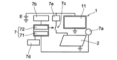
- FIG. 7 shows a block diagram of the main elements related to the control of energization of the membrane body 2.
- the mounting structure of the display device of the present embodiment includes the temperature measuring unit 7a, the timing unit 7b, the first control unit 71, and the first control unit 71 in addition to the display device 1 and the film body 2 described above. 2
- a control unit 7 including a control unit 72 and a switching element 7c are provided.
- the temperature measuring unit 7a monitors one or both of the temperature of the display screen 11 and the ambient temperature of the display screen 11.
- the first control unit 71 is connected to the temperature measuring unit 7a, and controls the energization of the film body 2 based on the output of the temperature measuring unit 7a.
- the timekeeping unit 7b is connected to the second control unit 72.
- the timekeeping unit 7b monitors, for example, the arrival of a preset time, and notifies the second control unit 72 of the arrival.
- the second control unit 72 controls the energization of the film body 2 based on the output of the time measuring unit 7b.
- the display device 1 and the film body 2 are connected to the power supply E in parallel.
- the film body 2 is connected to the power supply E via the switching element 7c.
- the booster circuit 7e described above is further provided.
- the booster circuit 7e is provided between the power source E and the film body 2, and increases the voltage applied to the film body 2 for energizing the film body 2.
- the booster circuit 7e is provided as needed.
- the switching element 7c has an input terminal for a signal that controls the open / closed state of the switching element 7c, and the output of the control unit 7 is input to this input terminal. Examples of the switching element 7c include semiconductor elements such as various transistors, switching ICs, and electromagnetic relays. In the example of FIG.
- the first and second control units 71 and 72 start or stop energization of the film body 2 by switching between the open state and the closed state of the switching element 7c, and energize the film body 2. Switch between the non-energized state and the non-energized state.
- Power source E is any external power source, such as a vehicle battery.
- the display device 1 and the film body 2 may be supplied with electric power via a stabilizing circuit such as a voltage regulator. Further, the film body 2 may be supplied with electric power from a power source different from the power source for the display device 1. Further, when the display device 1 has a power storage means such as a battery, electric power may be supplied from the display device 1 to the film body 2.
- the control unit 7 may be composed of a semiconductor integrated circuit such as a microcomputer, a gate array, or a programmable logic device that operates according to a control program consisting of a series of instruction sets.
- the first control unit 71 and the second control unit 72 are internal same functional blocks or different functional blocks such as a microcomputer constituting the control unit 7, and a series of instruction sets in a control program corresponding to those functional blocks. Can be composed of.
- the temperature measuring unit 7a is composed of an arbitrary detecting element capable of detecting the temperature around the display screen, such as the temperature sensor 12 (see FIG. 2) described above.
- the "temperature around the display screen" includes the temperature of the film body 2 and the temperature of the surface on which the film body 2 is provided (one surface 3a of the windshield 3 in the example of FIG. 1).
- Examples of the temperature measuring unit 7a include a thermistor, a thermocouple, an IC temperature sensor, and the like, but the detection element constituting the temperature measuring unit 7a is not limited to these.
- the first control unit 71 starts energizing the film body 2 when the temperature (detection temperature) detected by the temperature measuring unit 7a falls below the predetermined first temperature or falls below the first temperature. By doing so, dew condensation on the display screen 11 may be prevented. Further, the first control unit 71 stops the energization of the film body 2 when the detection temperature of the temperature measuring unit 7a becomes a predetermined second temperature or higher or exceeds the second temperature. By doing so, it may be possible to prevent the display device 1 from becoming overheated. When the display device 1 is an organic EL display device having relatively low heat resistance, such an overheat prevention function is particularly useful because an excessive temperature rise in eliminating dew condensation promotes a decrease in display characteristics and life. ..
- the timekeeping unit 7b is composed of, for example, a counter IC and a timer IC, and measures the passage of time.
- the timekeeping unit 7b is controlled by, for example, the control unit 7.
- the timekeeping unit 7b may be composed of a counter function block or a timer function block included in a microcomputer or the like constituting the control unit 7.
- the timekeeping unit 7b may have both a calendar function and a 24-hour clock function according to the time system.
- the timekeeping unit 7b notifies the second control unit 72 of the arrival of a preset time and / or the passage of a preset time.
- the time measuring unit 7b may, for example, measure the elapsed time from the start of energization of the film body 2 or may measure the elapsed time from the stop of energization of the film body 2.
- the second control unit 72 controls the energization of the film body 2 based on the output of the timekeeping unit 7b. For example, the second control unit 72 starts energizing the film body 2 when it receives the output of the time measuring unit 7b that notifies the arrival of a predetermined time. By doing so, when the vehicle is used at the scheduled time every day, it may be possible to eliminate the dew condensation that has already occurred before the user gets on board. Further, the second control unit 72 stops the energization of the film body 2 when, for example, receives the output of the time measuring unit 7b that notifies that a predetermined time has elapsed from the start of energization of the film body 2.
- the time measuring unit 7b so as to notify the passage of time when the dew condensation is expected to be eliminated, the energization of the film body 2 is automatically stopped after the dew condensation is eliminated to prevent waste of electric power. be able to.
- a communication unit 7d is further provided and connected to the control unit 7.
- the communication unit 7d exchanges signals with an external electronic device via an arbitrary communication protocol such as Bluetooth (registered trademark) or an arbitrary communication network such as a mobile phone network.
- the communication unit 7d communicates with a mobile device such as a smartphone owned by the user of the vehicle, and transmits an instruction transmitted from the user to the control unit 7.
- the control unit 7 starts energizing the film body 2 based on the dew condensation elimination instruction sent from the user.
- the communication unit 7d may be composed of a communication control module such as a Bluetooth (registered trademark) module, for example.
- the mounting structure of the display device of the present embodiment has two display devices, that is, the first display device 1a and the second display device, as display devices mounted on one surface facing the vehicle interior via the film body 2.
- the first display device 1a and the second display device 1b are attached to one surface of the windshield 3 of the automobile C facing the vehicle interior.
- the automobile C in the example of FIG. 8 is not provided with the side mirror SM as depicted by the alternate long and short dash line in FIG.
- the automobile C is provided with a first image pickup device 9a for photographing the left rear view of the automobile C and a second image pickup device 9b for photographing the right rear view of the automobile C.
- the first and second image pickup devices 9a and 9b are generally attached to the outside of the left and right doors to which the side mirror (door mirror) SM is attached.
- the first and second image pickup devices 9a and 9b are digital cameras having, for example, a CCD image sensor or a CMOS image sensor.
- the first display device 1a displays at least the left rear view of the vehicle (vehicle C) taken by the first image pickup device 9a. Further, the second display device 1b displays at least the right rear view of the automobile C taken by the second image pickup device 9b.
- display target data is selected from the captured image data generated by each imaging device, and the display target data is displayed image data suitable for each display device. It is provided with a processing circuit that converts to and enlarges or reduces the image as needed.
- the first and second display devices 1a and 1b are attached to the lower region of the windshield 3 as in the display device 1 of the example of FIG. Therefore, the driver M can quickly switch the focal position of the eyes between when looking at the scene outside the vehicle ahead and when looking at the first display device 1a or the second display device 1b.
- the first display device 1a is attached to the intersection of the left end of the front edge of the automobile C on the windshield 3 and the virtual straight line IL1 connecting the driver's seat DS of the automobile C in the top view.
- the second display device 1b is attached to the intersection of the right end of the front edge of the automobile C on the windshield 3 and the virtual straight line IL2 connecting the driver's seat DS of the automobile C in the top view.
- the driver M can see the scene in the direction corresponding to his / her movement with respect to the left and right, as compared with the case where both the left and right scenes are displayed close to each other in the central portion in the vehicle width direction, for example. Therefore, it is presumed that there is little misunderstanding regarding the left and right in the safety confirmation behind the driver M.
- the rounded portion is the left end portion or the right end portion.
- the virtual straight lines IL1 and IL2 are straight lines connecting any part of the rounded portion with the driver's seat DS. Further, the virtual straight lines IL1 and IL2 are straight lines connecting any part of the driver's seat DS in the vehicle width direction with the left end portion or the right end portion of the front edge of the automobile C, respectively.
- the first display device 1a is attached so as to overlap the intersection of the windshield 3 and the virtual straight line IL1
- the second display device 1b is attached to the windshield 3 and the virtual straight line IL2. It means that it will be installed so that it overlaps the intersection.
- FIG. 9A and 9B show another example of the mounting structure of this embodiment, which comprises a windshield 8 which is an example of means for blocking hot air toward the display device 1.
- 9B is a cross-sectional view taken along the line IXB-IXB of FIG. 9A.
- the mounting structure of the display device of the examples of FIGS. 9A and 9B includes the display device 1 and the film body 2, and further includes a windshield 8 against the wind blowing into the display screen 11.
- the display device 1 is attached to one surface 3a of the windshield 3 via a film body 2.
- the display device 1 is provided in the lower region of the windshield 3 as in the example of FIG. Therefore, although not shown in FIGS. 9A and 9B, a defroster outlet B (see FIG. 1) is provided further below the display device 1. Therefore, the windshield 8 is provided between the display device 1 and the lower edge of the windshield 3, for example, on one surface 3a of the windshield 3 in order to block the wind blowing into the display screen 11 mainly from below.
- the windshield 8 has a plate-like shape having a longitudinal direction and being curved two-dimensionally.
- the windshield 8 has substantially the same length in the longitudinal direction as the length in the longitudinal direction of the display device 1.
- One end surface (side surface) along the longitudinal direction of the windshield 8 is fixed to one surface 3a of the windshield 3, and a partition wall made of the windshield 8 is formed between the display device 1 and the outlet of the defroster (not shown). ing. Therefore, the windshield 8 can block the wind H blown from the outlet of the defroster toward the display screen 11.
- the windshield 8 is preferably provided so as not to cover the display screen 11.
- the windshield 8 may be formed by using a material having translucency, and in that case, the display screen 11 may be covered by the windshield 8.
- the material of the windshield 8 is not particularly limited, and any synthetic resin, metal, or the like can be used.
- the windshield 8 is formed by using a material capable of having translucency such as acrylic or silicone, and the means for fixing the windshield 8 to one surface 3a is not particularly limited.
- an epoxy-based or acrylic-based adhesive is used for fixing the windshield 8 to one surface 3a.
- the film body 2 has a front shape larger than that of the display device 1, and the film body 2 has an exposed portion 24 that is not covered by the display device 1.
- the film body 2 has a relatively large exposed portion 24 on the right and left sides of the display device 1 in the vehicle width direction (X direction in FIG. 9A) and on the upper side in the vertical direction of the vehicle (Y direction in FIG. 9A).
- the exposed portion 24 of the film body 2 can be used to promote the heating of the display screen 11.
- the windshield 8 is provided so that the wind H toward the display device 1, such as hot air from the defroster, is blown into the exposed portion 24 without being blown into the display device 1.
- the windshield 8 is provided with a portion that functions as a guide for directing the wind H from the outlet of the defroster toward the display device 1 toward the exposed portion 24. By doing so, it is possible to prevent the hot air from the defroster from blowing into the display device 1 and to promote the heating of the display device 1 by using the heat of the hot air.
- the windshield 8 has an outer surface 8a that is directed in the direction opposite to the display device 1 and faces the wind H that hits the windshield 8, and the outer surface 8a is convex in the direction opposite to the display device 1. It is curved so that it becomes.
- the outer surface 8a protrudes most in the central portion in the vehicle width direction in the direction opposite to the display device 1. That is, the outer surface 8a is closest to the outlet of the defroster (not shown) at the central portion in the vehicle width direction, and is closest to the display device 1 and the film body 2 at both ends in the vehicle width direction. Therefore, the wind H blown to the windshield 8 flows along the curved outer surface 8a in the XY plane shown in FIG. 9A, and reaches the exposed portion 24 of the film body 2 exposed on the right side and the left side of the display device 1, respectively. Is guided.
- the windshield 8 is curved so as to be convex in the direction opposite to the display device 1 even in the front-rear direction of the vehicle (Z direction in FIG. 9B). Therefore, the wind H blown to the windshield 8 flows to the end of the windshield 8 along the outer surface 8a even in the YY plane shown in FIG. 9B. Then, the wind H flowing out from the end portion of the windshield 8 rises toward the windshield 3 because its temperature is higher than the ambient air, and hits the exposed portion 24 on the upper side of the display device 1 in the film body 2.
- the windshield 8 has, as the outer surface 8a, a guide portion extending to the exposed portion 24 so as to direct the wind H corresponding to the windshield 8 to the exposed portion 24 of the film body 2.
- the wind H guided to the exposed portion 24 along the outer surface 8a heats the exposed portion 24.
- the film body 2 that can be formed of ITO or the like can generally have a higher thermal conductivity than the windshield 3. Therefore, the heat of the exposed portion 24 is efficiently conducted to the portion of the film body 2 covered by the display device 1. Therefore, the heat can accelerate the heating of the display device 1.
- the shape of the windshield 8 is not limited to the examples of FIGS. 9A and 9B. It can function as a windshield 8 as long as it can at least weaken the wind blowing into the display device 1.
- FIG. 10 shows an example of the mounting structure of the display device according to the second embodiment of the present disclosure.
- the display device 1c includes a film-shaped heater 13.
- the heater 13 is provided on the opposite surface (non-display surface 1ca) of one surface of the display device 1c including the display screen 11.
- the display device 1c is arranged on the film body 2 via the weak adhesive layer 14.
- the holding member 4 shown in FIG. 2 and the like is omitted in FIG. 10, the holding member 4 may be used in the present embodiment as well.
- the mounting structure of the display device of the present embodiment is the same as the mounting structure of the display device of the first embodiment described with reference to FIG. 2 and the like. The description of the same components as in the first embodiment will be omitted.
- the weak adhesive layer 14 is interposed between the display device 1c and the film body 2, so that the display device 1c (specifically, the heater 13 in the present embodiment) and the film body 2 are in close contact with each other. To do. Therefore, floating from the windshield 3 during use of the display device 1c and entrainment of air bubbles at the interface between the display device 1c and the film body 2 are prevented.
- weak adhesive adheres exactly to the adherend, it can be easily peeled off without damaging the adherend and without leaving glue or the like on the adherent surface by simply applying force in the peeling direction. It means the degree of adhesion that can be obtained.
- the adhesion strength between the weak adhesive layer 14 and either or both of the display device 1c and the film body 2 is, for example, 0.02 N / 10 mm or more and 5.0 N / 10 mm or less, preferably 1.5 N / 10 mm or more. , 2.0 N / 10 mm or less. If the adhesion strength in this range is obtained, it is considered unlikely that the display device 1c will peel off from the film body 2 during use of the display device 1c.
- the display device 1c can be easily removed from the one side 3a by simply pulling the display device 1c with an appropriate force or inserting a thin plate into the interface to inject air. Can be done. For example, when the display device 1c is damaged, the display device 1c can be easily replaced.
- the weak adhesive layer 14 is composed of, for example, an adhesive containing an acrylic, silicone, or urethane resin alone or in combination of two or more as a main component.
- an acrylic or silicone-based resin that can have transparency is suitable as a material for the weak adhesive layer 14.
- the weak adhesive layer 14 contains, for example, these resins as main components. It is formed by arranging a weak adhesive sheet in which the adhesive material to be used is formed into a predetermined shape between the display device 1c and the film body 2.
- the heater 13 is an arbitrary heating element formed on the non-display surface 1ca of the display device 1c.
- the heater 13 is formed on the non-display surface 1ca using a material having an appropriate electric resistance that generates Joule heat when energized, like the film body 2.
- the material of the heater 13 include ITO, zinc oxide, titanium, chromium, rhodium, nickel, and aluminum, as in the case of the film body 2.
- the film-shaped heater 13 may have a plurality of regions and meanders, as in the case of the film bodies 2 and the film bodies 2a to 2d exemplified in FIGS. 4, 5 and 6A to 6D. It may have a shape to be used.
- the heater 13 may be patterned so as to have an arbitrary front shape. It is preferable that the patterning of the heater 13 is performed so that the display screen 11 of the display device 1c can be heated as uniformly as possible by using a thermal simulation. By doing so, it is possible to prevent a decrease in local display characteristics and life due to uneven heating of the display screen 11.
- the power supply source to the heater 13 is not particularly limited.
- the heater 13 may be supplied with power from a power storage means such as a battery included in the display device 1c, or may be supplied from an external power source (not shown) via the power supply path 23 like the film body 2. ..
- the heater 13 and the film body 2 may be connected in parallel.
- the display screen 11 of the display device 1c can be heated more quickly.
- the heat conducted from the film body 2 may be efficiently diffused in all directions along the display screen 11.
- the weak adhesive layer 14 may also have a function as an insulating material between the film body 2 and the heater 13.
- the weak adhesive layer 14 may be used without the heater 13, or the heater 13 may be provided together with an appropriate insulating material without using the weak adhesive layer 14.
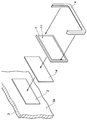
- a film body 2 capable of passing an electric current is provided on a predetermined plane or curved surface (one surface 3a in FIG. 11) facing the interior of the vehicle, and a display having a display screen 11 is provided.
- the device 1 includes attaching the display screen 11 to the room and mounting the display screen 11 on one surface 3a via the film body 2.
- the display device 1 in the present embodiment may be any of the display device 1 and the display devices 1a to 1c in the embodiment described with reference to FIGS. 1 to 10.
- the film body 2 in the present embodiment can be any of the film bodies 2 and the film bodies 2a to 2d in the embodiments described with reference to FIGS. 1 to 10.
- One surface 3a of the example shown in FIG. 11 is a surface of the windshield 3 of the vehicle facing the passenger compartment.
- the film body 2 is formed by depositing a material having appropriate conductivity such as ITO, zinc oxide, titanium, chromium, rhodium, nickel, and aluminum on one surface 3a by a method such as sputtering or printing.
- the film body 2 to be filmed is formed, for example, at 1 nm or more and 1000 nm or less.
- the film body 2 is preferably formed to have a thickness of 100 nm or more and 500 nm or less.
- the film body 2 is made of a metal material, it is preferable to form the film body 2 having a thickness of 2 nm or more and 20 nm or less so as to have translucency.
- the film body 2 is as illustrated in FIG. It may be formed in a solid shape without gaps, and only a predetermined region may be formed so as to include an arbitrary number of regions separated from each other or to have a desired front shape as illustrated in FIGS. 6A to 6D. It may be formed into a film.
- the feeding path 23 shown in FIG. 2 and the electrode 21 shown in FIG. 4 may be formed on one surface 3a by sputtering or the like.
- the film body 2 having appropriate conductivity generates heat when energized.
- the display device 1 is attached to one surface 3a via the film body 2 so that the display screen 11 is warmed by the heat generated based on the energization of the film body 2. That is, the display device 1 is attached so that a thermal resistance that allows the temperature of the display screen 11 to rise with the heat generated by the film body 2 is obtained between the film body 2 and the display screen 11.
- the display device 1 may be attached so that the non-display surface opposite to the display screen 11 faces the film body 2 so that the non-display surface and the film body 2 are in direct contact with each other.
- the display device 1 uses an arbitrary adhesive, preferably an optical transparent adhesive (OCA: Optical Clear Adhesive), an optical transparent resin (OCR: Optical Clear Resin), or the like, and the film body 2 and the display device 1. It is adhered to one side 3a. Further, when sufficient heat conduction is obtained between the film body 2 and the display screen 11, the display device 1 is arranged on the film body 2 via the weak adhesive layer 14 as shown in FIG. May be done. That is, the method of attaching the display device of the present embodiment may include interposing a weak adhesive layer 14 between the film body 2 and the display device 1. The display device 1 may be mounted on one side 3a due to the adhesiveness of the weak adhesive layer 14 without using an adhesive (not shown).
- OCA optical Clear Adhesive
- OCR optical transparent resin
- the display device 1 may be fixed to one side 3a by using the holding member 4. That is, the method of attaching the display device of the present embodiment is to bond the holding member 4 to one surface 3a and to engage the holding member 4 and the display device 1 before or after the bonding, or at the same time. It may be further included.
- the holding member 4 the holding member 4 in the embodiment described with reference to FIGS. 1 and 2 can be used.
- the holding member 4 can be adhered to one side 3a using any adhesive, preferably OCA, OCR, or the like.
- the display device 1 can be fixed at a predetermined position on one surface 3a by holding the edge portion by the holding member 4.
- the dew condensation prevention method of the present embodiment is used, for example, in the display device 1 having the mounting structure of the display device of one embodiment shown in FIGS. 1 to 10.
- the dew condensation prevention method of the present embodiment will be described by taking the display device 1 shown in FIGS. 1 to 4 as an example.
- the dew condensation prevention method of the display device of the present embodiment faces a predetermined flat surface or curved surface (for example, the vehicle interior R of the windshield 3 in FIG. 1) facing the interior of the vehicle (for example, automobile C). It includes generating heat in the film body 2 by passing an electric current through the film body 2 provided on the one surface 3a). The energization of the film body 2 is performed, for example, by applying an appropriate voltage between any two points of the film body 2, preferably between the two most distant points in the film body 2. .. As shown in FIG. 4, when the film body 2 includes a pair of electrodes 21, a voltage is applied between the pair of electrodes 21. Further, when the film body 2 has a shape defining a current path as illustrated in FIGS. 6B and 6C, a voltage is applied between one end of the current path and the other end opposite to the one end. ..
- the method for preventing dew condensation on the display device of the present embodiment is to heat the display screen 11 of the display device 1 attached to one surface 3a via the film body 2 by using the heat generated by energizing the film body 2. And, by the heating, it includes preventing the adhesion of water droplets to the display screen 11. If at least the temperature of the display screen 11 can be raised higher than the temperature around it, the possibility that the amount of water vapor in the air on the display screen 11 exceeds the saturated water vapor amount can be reduced, and water droplets on the display screen 11 can be reduced. Adhesion can be prevented. Therefore, it is possible to prevent water droplets from adhering to the display screen 11 by generating heat in the film body 2 to such an extent that the temperature of the display screen 11 can be raised.
- the specific heat capacity Cp of the display device 1 is 1.5 J / g ⁇ ° C. and its mass is 30 g
- a current of 600 mA or more is passed through the film body 2, for example.
- the upper limit of the current flowing through the film body 2 is defined from the viewpoint of preventing overheating of the film body 2 or the display device 1, and is, for example, 1000 mA or less.
- the film body 2 having an electric resistance of 20 ⁇ can generate heat that can raise the temperature of the display screen 11 by 10 ° C. in one minute, and the temperature of the display screen 11 can be raised. The rise can be kept below 30 ° C.
- energization of the film body 2 is started based on the detection result of the temperature detection means such as the display device 1 or the temperature sensor 12 (see FIG. 2) provided in the vehicle interior. It may include switching between and stop. For example, when the detected temperature detected by the temperature sensor 12 becomes equal to or lower than the predetermined first temperature or lower than the predetermined first temperature, energization of the film body 2 is started and the detected temperature becomes equal to or higher than the predetermined second temperature. When the temperature exceeds the second temperature, the energization of the film body 2 may be stopped.
- a desired time has arrived or a desired time has been desired by using a time measuring means such as a counter or a timer provided in the display device 1 or the vehicle interior. It may include switching between starting and stopping the energization of the film body 2 based on the passage of time.
- the mounting structure of the display device according to the first embodiment of the present disclosure is provided on one surface consisting of a display device having a display screen for displaying an image and a predetermined flat surface or curved surface facing the interior of the vehicle to transmit a current.
- the display device includes a film body that can be passed through, and the display device is such that the display screen is directed toward the room and the display screen is warmed by heat generated based on energization of the film body. It is attached to the one surface via the above.
- the film body may include two or more regions electrically separated from each other. In that case, the uniformity of the heat generation distribution in the entire film body may be improved.
- the film body and the display device may be formed by using a material having translucency. In that case, a person in the vehicle interior can see the scene beyond the display device through the display device.
- the film body has an electrical conductivity of 0.1 ⁇ 10 6 S / m or more and 7 ⁇ 10 7 S / m or less. May have.
- an inorganic compound such as ITO or a metal having translucency can be used as the material of the film body.
- the film body may be provided with a separating portion for partially dividing the film body. In that case, the stress generated in the film body may be relaxed.
- one surface thereof is a surface facing the passenger compartment in the windshield of an automobile, and the display device is the windshield of the automobile. It may be mounted below the center of the vehicle in the vertical direction. In that case, the driver may be able to quickly switch the focus of the eyes.
- the mounting structure of the display device according to any one of (1) to (6) is the first display device for displaying the left rear view of the vehicle and the right rear view of the vehicle as the display device. It may include a second display device for displaying. In that case, the safety behind both the left and right can be confirmed.
- the one surface is a surface facing the passenger compartment on the windshield of the automobile
- the first display device is the front edge of the automobile on the windshield.
- the second display device attached to the intersection of the left end of the vehicle and the virtual straight line connecting the driver's seat of the vehicle, connects the right end of the front edge of the vehicle on the windshield and the driver's seat of the vehicle. It may be attached at the intersection with the virtual straight line. In that case, it may be possible to reduce misunderstandings regarding left and right in the safety confirmation behind the driver.
- the mounting structure of the display device is a temperature measuring unit that monitors one or both of the temperature of the display screen and the ambient temperature of the display screen, and the temperature measuring unit.
- a first control unit that controls energization of the film body based on the output of the temperature unit may be further provided. In that case, the film body can be appropriately heated according to the temperature of the display device and / or its surroundings.
- the mounting structure of the display device includes a time measuring unit that monitors the arrival of a preset time and energization of the film body based on the output of the time measuring unit.
- a second control unit for controlling the above may be further provided. In that case, heat generation can be automatically started or stopped in the film body at a desired timing.
- the mounting structure of the display device according to any one of (1) to (10) may further include a windshield against the wind blowing into the display screen.
- the display device can be protected from hot air such as a defroster.
- the film body has an exposed portion not covered by the display device, and the windshield does not blow the wind toward the display device into the display device. May be provided so as to blow into the exposed portion. In that case, the heat of the wind toward the display device may be used to promote the heating of the display screen.
- the windshield may have a portion extending to the exposed portion so as to direct the wind hitting the windshield toward the exposed portion. In that case, the wind toward the display device can be efficiently directed to the exposed portion of the film body.
- the display device may be provided with a film-like heater on the opposite surface of the display device including the display screen. In that case, the heating of the display screen can be promoted.
- the mounting structure of the display device according to any one of (1) to (14) may further include a booster circuit that increases the voltage applied to the film body in order to allow a current to flow through the film body. .. In that case, the current flowing through the film body can be reduced.
- the mounting structure of the display device according to any one of (1) to (15) is an insulating coating film covering the power supply path formed on one surface as a power supply path to the film body. You may also have more. In that case, electric shock can be prevented.
- the method of attaching the display device according to the second embodiment of the present disclosure is to provide a display device having a display screen by providing a film body capable of passing current on a predetermined plane or curved surface facing the interior of the vehicle.
- the present invention includes mounting the display screen toward the room and on the predetermined flat surface or curved surface via the film body so that the display screen is warmed by heat generated based on energization of the film body. According to this embodiment, it is possible to easily prevent or eliminate the deterioration of the visibility of the displayed image due to the change in the surrounding environment.
- the method for preventing dew condensation on the display device causes heat to be generated in the film body by passing an electric current through the film body provided on a predetermined flat surface or curved surface facing the interior of the vehicle.
- the present invention includes preventing the adhesion of water droplets to the display screen by warming the display screen of the display device attached to the predetermined flat surface or curved surface via the film body by using the heat. According to this embodiment, it is possible to prevent dew condensation on the display device and prevent deterioration of visibility.
Landscapes
- Engineering & Computer Science (AREA)
- Mechanical Engineering (AREA)
- Chemical & Material Sciences (AREA)
- Combustion & Propulsion (AREA)
- Transportation (AREA)
- Devices For Indicating Variable Information By Combining Individual Elements (AREA)
Priority Applications (2)
| Application Number | Priority Date | Filing Date | Title |
|---|---|---|---|
| PCT/JP2019/013821 WO2020194722A1 (ja) | 2019-03-28 | 2019-03-28 | 表示装置の取り付け構造、表示装置の取り付け方法、及び、表示装置の結露防止方法 |
| JP2021508645A JPWO2020194722A1 (https=) | 2019-03-28 | 2019-03-28 |
Applications Claiming Priority (1)
| Application Number | Priority Date | Filing Date | Title |
|---|---|---|---|
| PCT/JP2019/013821 WO2020194722A1 (ja) | 2019-03-28 | 2019-03-28 | 表示装置の取り付け構造、表示装置の取り付け方法、及び、表示装置の結露防止方法 |
Publications (1)
| Publication Number | Publication Date |
|---|---|
| WO2020194722A1 true WO2020194722A1 (ja) | 2020-10-01 |
Family
ID=72611294
Family Applications (1)
| Application Number | Title | Priority Date | Filing Date |
|---|---|---|---|
| PCT/JP2019/013821 Ceased WO2020194722A1 (ja) | 2019-03-28 | 2019-03-28 | 表示装置の取り付け構造、表示装置の取り付け方法、及び、表示装置の結露防止方法 |
Country Status (2)
| Country | Link |
|---|---|
| JP (1) | JPWO2020194722A1 (https=) |
| WO (1) | WO2020194722A1 (https=) |
Citations (6)
| Publication number | Priority date | Publication date | Assignee | Title |
|---|---|---|---|---|
| JPS60124533A (ja) * | 1983-12-08 | 1985-07-03 | Toyota Motor Corp | 自動車用投影式メ−タ表示装置 |
| JP2008126973A (ja) * | 2006-11-24 | 2008-06-05 | Calsonic Kansei Corp | 車両用ヘッドアップディスプレイ部構造 |
| WO2014112649A1 (ja) * | 2013-01-21 | 2014-07-24 | 旭硝子株式会社 | 電熱窓用板状体 |
| WO2015041106A1 (ja) * | 2013-09-18 | 2015-03-26 | 旭硝子株式会社 | 合わせガラスおよび車両用表示装置 |
| WO2017157660A1 (de) * | 2016-03-17 | 2017-09-21 | Saint-Gobain Glass France | Verbundscheibe mit elektrisch leitfähiger beschichtung für ein head-up-display |
| JP2019026048A (ja) * | 2017-07-28 | 2019-02-21 | マツダ株式会社 | 車両の防曇制御装置 |
Family Cites Families (11)
| Publication number | Priority date | Publication date | Assignee | Title |
|---|---|---|---|---|
| JPS61228419A (ja) * | 1986-01-23 | 1986-10-11 | Seiko Epson Corp | 液晶防眩装置 |
| JPH0492397U (https=) * | 1990-12-28 | 1992-08-11 | ||
| JPH06260265A (ja) * | 1993-02-27 | 1994-09-16 | Daido Maruta Senko Kk | 透明面状発熱体 |
| JPH07153559A (ja) * | 1993-12-02 | 1995-06-16 | Toyobo Co Ltd | 透明シート状ヒーター |
| JP2616459B2 (ja) * | 1994-09-26 | 1997-06-04 | 日本電気株式会社 | 車載用表示装置 |
| JPH08234679A (ja) * | 1995-02-24 | 1996-09-13 | Hitachi Ltd | ディスプレイ装置 |
| JPH11198679A (ja) * | 1998-01-14 | 1999-07-27 | Harness Syst Tech Res Ltd | 表示装置 |
| US7265323B2 (en) * | 2001-10-26 | 2007-09-04 | Engineered Glass Products, Llc | Electrically conductive heated glass panel assembly, control system, and method for producing panels |
| JP4472272B2 (ja) * | 2003-05-30 | 2010-06-02 | 株式会社半導体エネルギー研究所 | 表示装置システム |
| JP2009086046A (ja) * | 2007-09-27 | 2009-04-23 | Nissan Motor Co Ltd | 調光装置 |
| US10658627B2 (en) * | 2017-09-07 | 2020-05-19 | Sakai Display Products Corporation | Method for manufacturing a display apparatus |
-
2019
- 2019-03-28 JP JP2021508645A patent/JPWO2020194722A1/ja active Pending
- 2019-03-28 WO PCT/JP2019/013821 patent/WO2020194722A1/ja not_active Ceased
Patent Citations (6)
| Publication number | Priority date | Publication date | Assignee | Title |
|---|---|---|---|---|
| JPS60124533A (ja) * | 1983-12-08 | 1985-07-03 | Toyota Motor Corp | 自動車用投影式メ−タ表示装置 |
| JP2008126973A (ja) * | 2006-11-24 | 2008-06-05 | Calsonic Kansei Corp | 車両用ヘッドアップディスプレイ部構造 |
| WO2014112649A1 (ja) * | 2013-01-21 | 2014-07-24 | 旭硝子株式会社 | 電熱窓用板状体 |
| WO2015041106A1 (ja) * | 2013-09-18 | 2015-03-26 | 旭硝子株式会社 | 合わせガラスおよび車両用表示装置 |
| WO2017157660A1 (de) * | 2016-03-17 | 2017-09-21 | Saint-Gobain Glass France | Verbundscheibe mit elektrisch leitfähiger beschichtung für ein head-up-display |
| JP2019026048A (ja) * | 2017-07-28 | 2019-02-21 | マツダ株式会社 | 車両の防曇制御装置 |
Also Published As
| Publication number | Publication date |
|---|---|
| JPWO2020194722A1 (https=) | 2020-10-01 |
Similar Documents
| Publication | Publication Date | Title |
|---|---|---|
| US7446924B2 (en) | Mirror reflective element assembly including electronic component | |
| JP6594203B2 (ja) | 照明手段、および光透過率制御手段を含むガラスルーフ | |
| US10315573B2 (en) | Method for displaying information to vehicle driver | |
| US10214157B2 (en) | Forward viewing camera module for vehicular vision system | |
| JP6920330B2 (ja) | 車両用センサーシステムのハイブリッドヒーター | |
| KR101468829B1 (ko) | 차량 내 이미지 기록 장치를 위한 장치 | |
| EP3670233B1 (en) | Vehicle with a display device | |
| US20150321621A1 (en) | Vehicle vision system camera with graphene lens | |
| KR102461245B1 (ko) | 접는 외부 디스플레이 미러 | |
| CN111386193B (zh) | 包括具有可电控光学性能的可区段状切换的功能元件的复合玻璃板 | |
| JP2015527948A (ja) | 照明手段を含むサンルーフ | |
| JP2020082837A (ja) | ウィンドウガラス加熱装置 | |
| CN107076852A (zh) | 用于车辆传感器系统的透射式正面加热器 | |
| CN113840408B (zh) | 车窗总成及车辆 | |
| US20180124878A1 (en) | Rear-view Assembly for a Motor Vehicle with a Heating Device | |
| CN111886133B (zh) | 具有可电控光学性能的复合玻璃板以及复合玻璃板组合件 | |
| WO2021117352A1 (ja) | 窓ガラスシステム、及び、窓ガラス装置 | |
| JP7555936B2 (ja) | 窓ガラスの防曇構造 | |
| WO2020194722A1 (ja) | 表示装置の取り付け構造、表示装置の取り付け方法、及び、表示装置の結露防止方法 | |
| WO2020194723A1 (ja) | 表示装置、及び、表示装置の取り付け構造 | |
| JP2021044097A (ja) | スクリーンヒーターシステム | |
| JP7456144B2 (ja) | 表示装置 | |
| WO2020194724A1 (ja) | 表示装置及び表示装置の取り付け構造 | |
| KR20220056239A (ko) | 전기적으로 제어가능한 광학 특성들을 갖는 복합 판유리 | |
| WO2023277073A1 (ja) | 車両用ガラスモジュール |
Legal Events
| Date | Code | Title | Description |
|---|---|---|---|
| 121 | Ep: the epo has been informed by wipo that ep was designated in this application |
Ref document number: 19921717 Country of ref document: EP Kind code of ref document: A1 |
|
| ENP | Entry into the national phase |
Ref document number: 2021508645 Country of ref document: JP Kind code of ref document: A |
|
| NENP | Non-entry into the national phase |
Ref country code: DE |
|
| 122 | Ep: pct application non-entry in european phase |
Ref document number: 19921717 Country of ref document: EP Kind code of ref document: A1 |