WO2020189264A1 - セラミックヒータ及びその製法 - Google Patents
セラミックヒータ及びその製法 Download PDFInfo
- Publication number
- WO2020189264A1 WO2020189264A1 PCT/JP2020/009002 JP2020009002W WO2020189264A1 WO 2020189264 A1 WO2020189264 A1 WO 2020189264A1 JP 2020009002 W JP2020009002 W JP 2020009002W WO 2020189264 A1 WO2020189264 A1 WO 2020189264A1
- Authority
- WO
- WIPO (PCT)
- Prior art keywords
- plate
- tubular shaft
- resistance heating
- heating element
- peripheral side
- Prior art date
- Legal status (The legal status is an assumption and is not a legal conclusion. Google has not performed a legal analysis and makes no representation as to the accuracy of the status listed.)
- Ceased
Links
Images
Classifications
-
- H—ELECTRICITY
- H05—ELECTRIC TECHNIQUES NOT OTHERWISE PROVIDED FOR
- H05B—ELECTRIC HEATING; ELECTRIC LIGHT SOURCES NOT OTHERWISE PROVIDED FOR; CIRCUIT ARRANGEMENTS FOR ELECTRIC LIGHT SOURCES, IN GENERAL
- H05B3/00—Ohmic-resistance heating
- H05B3/20—Heating elements having extended surface area substantially in a two-dimensional [2D] plane, e.g. plate-heater
- H05B3/22—Heating elements having extended surface area substantially in a two-dimensional [2D] plane, e.g. plate-heater non-flexible
- H05B3/28—Heating elements having extended surface area substantially in a two-dimensional [2D] plane, e.g. plate-heater non-flexible heating conductor embedded in insulating material
- H05B3/283—Heating elements having extended surface area substantially in a two-dimensional [2D] plane, e.g. plate-heater non-flexible heating conductor embedded in insulating material the insulating material being an inorganic material, e.g. ceramic
-
- H—ELECTRICITY
- H05—ELECTRIC TECHNIQUES NOT OTHERWISE PROVIDED FOR
- H05B—ELECTRIC HEATING; ELECTRIC LIGHT SOURCES NOT OTHERWISE PROVIDED FOR; CIRCUIT ARRANGEMENTS FOR ELECTRIC LIGHT SOURCES, IN GENERAL
- H05B3/00—Ohmic-resistance heating
- H05B3/10—Heating elements characterised by the composition or nature of the materials or by the arrangement of the conductor
- H05B3/12—Heating elements characterised by the composition or nature of the materials or by the arrangement of the conductor characterised by the composition or nature of the conductive material
- H05B3/14—Heating elements characterised by the composition or nature of the materials or by the arrangement of the conductor characterised by the composition or nature of the conductive material the material being non-metallic
- H05B3/141—Conductive ceramics, e.g. metal oxides, metal carbides, barium titanate, ferrites, zirconia, vitrous compounds
-
- C—CHEMISTRY; METALLURGY
- C04—CEMENTS; CONCRETE; ARTIFICIAL STONE; CERAMICS; REFRACTORIES
- C04B—LIME, MAGNESIA; SLAG; CEMENTS; COMPOSITIONS THEREOF, e.g. MORTARS, CONCRETE OR LIKE BUILDING MATERIALS; ARTIFICIAL STONE; CERAMICS; REFRACTORIES; TREATMENT OF NATURAL STONE
- C04B35/00—Shaped ceramic products characterised by their composition; Ceramics compositions; Processing powders of inorganic compounds preparatory to the manufacturing of ceramic products
- C04B35/01—Shaped ceramic products characterised by their composition; Ceramics compositions; Processing powders of inorganic compounds preparatory to the manufacturing of ceramic products based on oxide ceramics
- C04B35/10—Shaped ceramic products characterised by their composition; Ceramics compositions; Processing powders of inorganic compounds preparatory to the manufacturing of ceramic products based on oxide ceramics based on aluminium oxide
-
- C—CHEMISTRY; METALLURGY
- C04—CEMENTS; CONCRETE; ARTIFICIAL STONE; CERAMICS; REFRACTORIES
- C04B—LIME, MAGNESIA; SLAG; CEMENTS; COMPOSITIONS THEREOF, e.g. MORTARS, CONCRETE OR LIKE BUILDING MATERIALS; ARTIFICIAL STONE; CERAMICS; REFRACTORIES; TREATMENT OF NATURAL STONE
- C04B35/00—Shaped ceramic products characterised by their composition; Ceramics compositions; Processing powders of inorganic compounds preparatory to the manufacturing of ceramic products
- C04B35/515—Shaped ceramic products characterised by their composition; Ceramics compositions; Processing powders of inorganic compounds preparatory to the manufacturing of ceramic products based on non-oxide ceramics
- C04B35/58—Shaped ceramic products characterised by their composition; Ceramics compositions; Processing powders of inorganic compounds preparatory to the manufacturing of ceramic products based on non-oxide ceramics based on borides, nitrides, i.e. nitrides, oxynitrides, carbonitrides or oxycarbonitrides or silicides
- C04B35/581—Shaped ceramic products characterised by their composition; Ceramics compositions; Processing powders of inorganic compounds preparatory to the manufacturing of ceramic products based on non-oxide ceramics based on borides, nitrides, i.e. nitrides, oxynitrides, carbonitrides or oxycarbonitrides or silicides based on aluminium nitride
-
- C—CHEMISTRY; METALLURGY
- C04—CEMENTS; CONCRETE; ARTIFICIAL STONE; CERAMICS; REFRACTORIES
- C04B—LIME, MAGNESIA; SLAG; CEMENTS; COMPOSITIONS THEREOF, e.g. MORTARS, CONCRETE OR LIKE BUILDING MATERIALS; ARTIFICIAL STONE; CERAMICS; REFRACTORIES; TREATMENT OF NATURAL STONE
- C04B35/00—Shaped ceramic products characterised by their composition; Ceramics compositions; Processing powders of inorganic compounds preparatory to the manufacturing of ceramic products
- C04B35/622—Forming processes; Processing powders of inorganic compounds preparatory to the manufacturing of ceramic products
- C04B35/64—Burning or sintering processes
-
- C—CHEMISTRY; METALLURGY
- C04—CEMENTS; CONCRETE; ARTIFICIAL STONE; CERAMICS; REFRACTORIES
- C04B—LIME, MAGNESIA; SLAG; CEMENTS; COMPOSITIONS THEREOF, e.g. MORTARS, CONCRETE OR LIKE BUILDING MATERIALS; ARTIFICIAL STONE; CERAMICS; REFRACTORIES; TREATMENT OF NATURAL STONE
- C04B37/00—Joining burned ceramic articles with other burned ceramic articles or other articles by heating
- C04B37/003—Joining burned ceramic articles with other burned ceramic articles or other articles by heating by means of an interlayer consisting of a combination of materials selected from glass, or ceramic material with metals, metal oxides or metal salts
- C04B37/005—Joining burned ceramic articles with other burned ceramic articles or other articles by heating by means of an interlayer consisting of a combination of materials selected from glass, or ceramic material with metals, metal oxides or metal salts consisting of glass or ceramic material
-
- C—CHEMISTRY; METALLURGY
- C04—CEMENTS; CONCRETE; ARTIFICIAL STONE; CERAMICS; REFRACTORIES
- C04B—LIME, MAGNESIA; SLAG; CEMENTS; COMPOSITIONS THEREOF, e.g. MORTARS, CONCRETE OR LIKE BUILDING MATERIALS; ARTIFICIAL STONE; CERAMICS; REFRACTORIES; TREATMENT OF NATURAL STONE
- C04B37/00—Joining burned ceramic articles with other burned ceramic articles or other articles by heating
- C04B37/003—Joining burned ceramic articles with other burned ceramic articles or other articles by heating by means of an interlayer consisting of a combination of materials selected from glass, or ceramic material with metals, metal oxides or metal salts
- C04B37/006—Joining burned ceramic articles with other burned ceramic articles or other articles by heating by means of an interlayer consisting of a combination of materials selected from glass, or ceramic material with metals, metal oxides or metal salts consisting of metals or metal salts
-
- H—ELECTRICITY
- H05—ELECTRIC TECHNIQUES NOT OTHERWISE PROVIDED FOR
- H05B—ELECTRIC HEATING; ELECTRIC LIGHT SOURCES NOT OTHERWISE PROVIDED FOR; CIRCUIT ARRANGEMENTS FOR ELECTRIC LIGHT SOURCES, IN GENERAL
- H05B3/00—Ohmic-resistance heating
- H05B3/02—Details
- H05B3/06—Heater elements structurally combined with coupling elements or holders
-
- H—ELECTRICITY
- H05—ELECTRIC TECHNIQUES NOT OTHERWISE PROVIDED FOR
- H05B—ELECTRIC HEATING; ELECTRIC LIGHT SOURCES NOT OTHERWISE PROVIDED FOR; CIRCUIT ARRANGEMENTS FOR ELECTRIC LIGHT SOURCES, IN GENERAL
- H05B3/00—Ohmic-resistance heating
- H05B3/10—Heating elements characterised by the composition or nature of the materials or by the arrangement of the conductor
- H05B3/16—Heating elements characterised by the composition or nature of the materials or by the arrangement of the conductor the conductor being mounted on an insulating base
-
- H—ELECTRICITY
- H05—ELECTRIC TECHNIQUES NOT OTHERWISE PROVIDED FOR
- H05B—ELECTRIC HEATING; ELECTRIC LIGHT SOURCES NOT OTHERWISE PROVIDED FOR; CIRCUIT ARRANGEMENTS FOR ELECTRIC LIGHT SOURCES, IN GENERAL
- H05B3/00—Ohmic-resistance heating
- H05B3/10—Heating elements characterised by the composition or nature of the materials or by the arrangement of the conductor
- H05B3/18—Heating elements characterised by the composition or nature of the materials or by the arrangement of the conductor the conductor being embedded in an insulating material
-
- H—ELECTRICITY
- H10—SEMICONDUCTOR DEVICES; ELECTRIC SOLID-STATE DEVICES NOT OTHERWISE PROVIDED FOR
- H10P—GENERIC PROCESSES OR APPARATUS FOR THE MANUFACTURE OR TREATMENT OF DEVICES COVERED BY CLASS H10
- H10P72/00—Handling or holding of wafers, substrates or devices during manufacture or treatment thereof
- H10P72/70—Handling or holding of wafers, substrates or devices during manufacture or treatment thereof for supporting or gripping
-
- H—ELECTRICITY
- H10—SEMICONDUCTOR DEVICES; ELECTRIC SOLID-STATE DEVICES NOT OTHERWISE PROVIDED FOR
- H10P—GENERIC PROCESSES OR APPARATUS FOR THE MANUFACTURE OR TREATMENT OF DEVICES COVERED BY CLASS H10
- H10P95/00—Generic processes or apparatus for manufacture or treatments not covered by the other groups of this subclass
-
- C—CHEMISTRY; METALLURGY
- C04—CEMENTS; CONCRETE; ARTIFICIAL STONE; CERAMICS; REFRACTORIES
- C04B—LIME, MAGNESIA; SLAG; CEMENTS; COMPOSITIONS THEREOF, e.g. MORTARS, CONCRETE OR LIKE BUILDING MATERIALS; ARTIFICIAL STONE; CERAMICS; REFRACTORIES; TREATMENT OF NATURAL STONE
- C04B2235/00—Aspects relating to ceramic starting mixtures or sintered ceramic products
- C04B2235/60—Aspects relating to the preparation, properties or mechanical treatment of green bodies or pre-forms
- C04B2235/602—Making the green bodies or pre-forms by moulding
- C04B2235/6023—Gel casting
-
- C—CHEMISTRY; METALLURGY
- C04—CEMENTS; CONCRETE; ARTIFICIAL STONE; CERAMICS; REFRACTORIES
- C04B—LIME, MAGNESIA; SLAG; CEMENTS; COMPOSITIONS THEREOF, e.g. MORTARS, CONCRETE OR LIKE BUILDING MATERIALS; ARTIFICIAL STONE; CERAMICS; REFRACTORIES; TREATMENT OF NATURAL STONE
- C04B2237/00—Aspects relating to ceramic laminates or to joining of ceramic articles with other articles by heating
- C04B2237/02—Aspects relating to interlayers, e.g. used to join ceramic articles with other articles by heating
- C04B2237/04—Ceramic interlayers
- C04B2237/06—Oxidic interlayers
- C04B2237/066—Oxidic interlayers based on rare earth oxides
-
- C—CHEMISTRY; METALLURGY
- C04—CEMENTS; CONCRETE; ARTIFICIAL STONE; CERAMICS; REFRACTORIES
- C04B—LIME, MAGNESIA; SLAG; CEMENTS; COMPOSITIONS THEREOF, e.g. MORTARS, CONCRETE OR LIKE BUILDING MATERIALS; ARTIFICIAL STONE; CERAMICS; REFRACTORIES; TREATMENT OF NATURAL STONE
- C04B2237/00—Aspects relating to ceramic laminates or to joining of ceramic articles with other articles by heating
- C04B2237/30—Composition of layers of ceramic laminates or of ceramic or metallic articles to be joined by heating, e.g. Si substrates
- C04B2237/32—Ceramic
- C04B2237/34—Oxidic
- C04B2237/343—Alumina or aluminates
-
- C—CHEMISTRY; METALLURGY
- C04—CEMENTS; CONCRETE; ARTIFICIAL STONE; CERAMICS; REFRACTORIES
- C04B—LIME, MAGNESIA; SLAG; CEMENTS; COMPOSITIONS THEREOF, e.g. MORTARS, CONCRETE OR LIKE BUILDING MATERIALS; ARTIFICIAL STONE; CERAMICS; REFRACTORIES; TREATMENT OF NATURAL STONE
- C04B2237/00—Aspects relating to ceramic laminates or to joining of ceramic articles with other articles by heating
- C04B2237/30—Composition of layers of ceramic laminates or of ceramic or metallic articles to be joined by heating, e.g. Si substrates
- C04B2237/32—Ceramic
- C04B2237/36—Non-oxidic
- C04B2237/366—Aluminium nitride
-
- C—CHEMISTRY; METALLURGY
- C04—CEMENTS; CONCRETE; ARTIFICIAL STONE; CERAMICS; REFRACTORIES
- C04B—LIME, MAGNESIA; SLAG; CEMENTS; COMPOSITIONS THEREOF, e.g. MORTARS, CONCRETE OR LIKE BUILDING MATERIALS; ARTIFICIAL STONE; CERAMICS; REFRACTORIES; TREATMENT OF NATURAL STONE
- C04B2237/00—Aspects relating to ceramic laminates or to joining of ceramic articles with other articles by heating
- C04B2237/50—Processing aspects relating to ceramic laminates or to the joining of ceramic articles with other articles by heating
- C04B2237/68—Forming laminates or joining articles wherein at least one substrate contains at least two different parts of macro-size, e.g. one ceramic substrate layer containing an embedded conductor or electrode
-
- C—CHEMISTRY; METALLURGY
- C04—CEMENTS; CONCRETE; ARTIFICIAL STONE; CERAMICS; REFRACTORIES
- C04B—LIME, MAGNESIA; SLAG; CEMENTS; COMPOSITIONS THEREOF, e.g. MORTARS, CONCRETE OR LIKE BUILDING MATERIALS; ARTIFICIAL STONE; CERAMICS; REFRACTORIES; TREATMENT OF NATURAL STONE
- C04B2237/00—Aspects relating to ceramic laminates or to joining of ceramic articles with other articles by heating
- C04B2237/50—Processing aspects relating to ceramic laminates or to the joining of ceramic articles with other articles by heating
- C04B2237/76—Forming laminates or joined articles comprising at least one member in the form other than a sheet or disc, e.g. two tubes or a tube and a sheet or disc
- C04B2237/765—Forming laminates or joined articles comprising at least one member in the form other than a sheet or disc, e.g. two tubes or a tube and a sheet or disc at least one member being a tube
-
- H—ELECTRICITY
- H05—ELECTRIC TECHNIQUES NOT OTHERWISE PROVIDED FOR
- H05B—ELECTRIC HEATING; ELECTRIC LIGHT SOURCES NOT OTHERWISE PROVIDED FOR; CIRCUIT ARRANGEMENTS FOR ELECTRIC LIGHT SOURCES, IN GENERAL
- H05B2203/00—Aspects relating to Ohmic resistive heating covered by group H05B3/00
- H05B2203/013—Heaters using resistive films or coatings
-
- H—ELECTRICITY
- H05—ELECTRIC TECHNIQUES NOT OTHERWISE PROVIDED FOR
- H05B—ELECTRIC HEATING; ELECTRIC LIGHT SOURCES NOT OTHERWISE PROVIDED FOR; CIRCUIT ARRANGEMENTS FOR ELECTRIC LIGHT SOURCES, IN GENERAL
- H05B2203/00—Aspects relating to Ohmic resistive heating covered by group H05B3/00
- H05B2203/016—Heaters using particular connecting means
-
- H—ELECTRICITY
- H05—ELECTRIC TECHNIQUES NOT OTHERWISE PROVIDED FOR
- H05B—ELECTRIC HEATING; ELECTRIC LIGHT SOURCES NOT OTHERWISE PROVIDED FOR; CIRCUIT ARRANGEMENTS FOR ELECTRIC LIGHT SOURCES, IN GENERAL
- H05B2203/00—Aspects relating to Ohmic resistive heating covered by group H05B3/00
- H05B2203/017—Manufacturing methods or apparatus for heaters
Definitions
- the present invention relates to a ceramic heater and a method for producing the same.
- Ceramic heaters for heating wafers are used in semiconductor manufacturing equipment.
- a ceramic heater as disclosed in Patent Document 1, a ceramic plate having a built-in resistance heating element, a ceramic tubular shaft joined to the lower surface of the plate, and a peripheral wall of the tubular shaft.
- a resistance heating element and a power feeding member electrically connected to each other by being inserted into through holes penetrating in the vertical direction. Since each feeding member is inserted through the through hole, there is no risk of electrical contact with each other, and even if there are a large number of resistance heating elements, it is possible to supply power to each through the feeding member. It is explained that it will be.
- Patent Document 1 since the feeding member is inserted through the through hole penetrating the peripheral wall of the tubular shaft in the vertical direction with play, the feeding member swings left and right in the through hole when stress is applied to the feeding member. There was a risk that the connection between the power feeding member and the resistance heating element would come off.
- the present invention has been made to solve such a problem, and an object of the present invention is to ensure the connection between the feeding member and the resistance heating element even if stress is applied to the feeding member.
- the ceramic heater of the present invention A ceramic plate with a wafer mounting surface on the upper surface and a resistance heating element embedded inside.
- the power feeding member is embedded in the peripheral wall of the tubular shaft and is in close contact with the ceramic material of the tubular shaft. Therefore, even if stress acts on the feeding member, the feeding member does not swing in the peripheral wall portion of the tubular shaft, and the bonding between the feeding member and the resistance heating element is ensured.
- top and bottom may be “left”, “right”, “front”, “rear”, “bottom”, and “top”.
- the tubular shaft may have an outward flange at the upper end, and the power feeding member may be electrically connected to the resistance heating element through the outward flange.
- the power feeding member may be electrically connected to the resistance heating element through the outward flange.
- the tubular shaft has a small diameter portion from the lower end to a predetermined height and an enlarged diameter portion having a diameter larger than the small diameter portion from the predetermined height to the upper end. May be good. In this way, even if a large number of resistance heating elements are provided, the power feeding member can be connected relatively easily for each resistance heating element.
- the plate has an inner peripheral side resistance heating element arranged in the inner peripheral zone of the plate and an outer peripheral side resistance heating element as the resistance heating element arranged in the outer peripheral zone of the plate. And may have.
- the power feeding member connected to the outer peripheral side resistance heating element is not arranged in the internal space of the tubular shaft. Therefore, the internal space of the tubular shaft can be used for another purpose.
- the inner peripheral side resistance heating element is electrically connected to the power feeding member arranged in the internal space of the tubular shaft via the inner peripheral side connection terminal, and the end face of the inner peripheral side connection terminal is the said. It may be located on the bottom surface of a hole provided on the lower surface of the plate. In this way, the internal space of the tubular shaft can be used to arrange the feeding member connected to the inner peripheral side resistance heating element. Further, the end face of the inner peripheral side connection terminal is located on the bottom surface of the hole provided on the lower surface of the plate, and such a structure allows the inner peripheral side connection terminal to be plated when the tubular shaft and the plate are joined.
- the method for producing a ceramic heater of the present invention is (A) First mold cast for manufacturing an inner wall of a ceramic tubular shaft A second mold for manufacturing an outer wall of a tubular shaft with a feeding member crawling in the vertical direction on the outer surface of the molded body. A step of obtaining a tubular molded body by arranging the mold cast molded body on the outer surface of the first mold cast molded body, and (B) A step of obtaining the tubular shaft by firing the tubular molded body, and (C) A step of preparing a ceramic plate in which a resistance heating element is embedded, in which connection terminals contacting both ends of the resistance heating element are exposed from the joint surface of the plate.
- this ceramic heater manufacturing method the above-mentioned ceramic heater can be manufactured relatively easily. That is, this manufacturing method is suitable for manufacturing the above-mentioned ceramic heater. Further, according to this manufacturing method, it is not necessary to make a through hole in the tubular shaft for inserting the feeding member, and at the same time as joining the tubular shaft and the plate, the feeding member and the resistance heating element are also joined. Therefore, the efficiency of the manufacturing operation is greatly improved.
- the tubular molded body has an outward flange, and is manufactured so that the feeding member passes through the outward flange, and the step (d). ),
- the power feeding member is exposed on the end surface of the outward flange of the tubular shaft, the metal bonding material is arranged between the power feeding member and the connection terminal, and the end surface of the outward flange and the power supply member are arranged.
- the plate and the tubular shaft may be joined by heating the plate while pressing the outward flange on the plate in a state where the ceramic bonding material is arranged between the joint surface of the plate.
- the tubular shaft has a small diameter portion from an end surface opposite to the joint surface of the tubular shaft to a predetermined height, and from the predetermined height to the joint surface. It may be a diameter-expanded portion having a diameter larger than that of the small-diameter portion. In this way, even if a large number of resistance heating elements are provided, the power feeding member can be connected relatively easily for each resistance heating element.
- the plate in the method for producing a ceramic heater of the present invention, in the step (c), has an inner peripheral side resistance heating element in the inner peripheral zone of the plate, and the outer peripheral zone of the plate has an outer peripheral portion as the resistance heating element.
- Those having a side resistance heating element may be prepared. In this way, the power feeding member connected to the outer peripheral side resistance heating element is not arranged in the internal space of the tubular shaft. Therefore, the internal space of the tubular shaft can be used for another purpose.
- the inner peripheral side resistance heating element is electrically connected to the power feeding member arranged in the internal space of the tubular shaft via the inner peripheral side connection terminal, and in the step (d).
- the inner peripheral side connection terminal is not exposed from the plate and is embedded in the plate.
- the said A hole may be provided in the plate to expose the end surface of the inner peripheral side connection terminal to the bottom surface of the hole.
- the internal space of the tubular shaft can be used to arrange the feeding member connected to the inner peripheral side resistance heating element. Further, it is possible to prevent the inner peripheral side connection terminal from being denatured when the tubular shaft and the plate are joined.
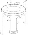
- FIG. 3 The perspective view of the ceramic heater 10.
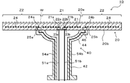
- a cross-sectional view taken along the line AA of FIG. 3 is a manufacturing process diagram of the tubular shaft 40.
- the manufacturing process diagram of the plate 20 Explanatory drawing which shows the joining process of a plate 20 and a tubular shaft 40.
- FIG. 5 is a cross-sectional view of another example of the ceramic heater 10.
- FIG. 1 is a perspective view of the ceramic heater 10
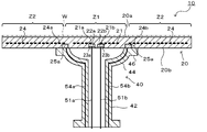
- FIG. 2 is a sectional view taken along the line AA of FIG.
- the ceramic heater 10 is used for heating a wafer to be subjected to a process such as etching or CVD, and is installed in a vacuum chamber (not shown).
- the ceramic heater 10 includes a ceramic plate 20 having a wafer mounting surface 20a on the upper surface thereof, and a ceramic tubular shaft 40 joined to the lower surface 20b of the plate 20.
- the plate 20 is a disk-shaped plate made of a ceramic material such as aluminum nitride or alumina.
- the diameter of the plate 20 is not particularly limited, but is, for example, about 300 mm.
- the plate 20 is divided into a small circular inner peripheral zone Z1 and an annular outer peripheral zone Z2 by a virtual boundary 20c (see FIG. 1) concentric with the plate 20.
- An inner peripheral side resistance heating element 21 is embedded in the inner peripheral zone Z1 of the plate 20, and an outer peripheral side resistance heating element 24 is embedded in the outer peripheral zone Z2.
- Both resistance heating elements 21 and 24 are composed of, for example, a coil containing molybdenum, tungsten or tungsten carbide as a main component.
- the tubular shaft 40 is made of ceramics such as aluminum nitride and alumina like the plate 20.
- the upper end of the tubular shaft 40 is solid-phase bonded or diffusion-bonded to the plate 20.
- the small diameter portion 42 has a constant diameter from the lower end to a predetermined height
- the enlarged diameter portion 44 has a diameter larger than that of the small diameter portion 42 from the predetermined height to the upper end.
- the diameter-expanded portion 44 has a shape in which the diameter increases as it approaches the upper end.
- An outward flange 46 is provided at the upper end of the tubular shaft 40.
- the inner peripheral side resistance heating element 21 is wired from one end 21a to almost the entire area of the inner zone Z1 while being folded back at a plurality of folded portions in a one-stroke manner, and then reaches the other of the other end 21b. It is formed like this.
- the ends 21a and 21b are provided in the inner region (inner shaft region) of the tubular shaft 40 in the plate 20.
- the end 21a is connected to the feeding member 51a via a columnar connecting terminal 22a
- the end 21b is connected to the feeding member 51b via a columnar connecting terminal 22b.
- the lower end surfaces of the connection terminals 22a and 22b are located on the bottom surfaces of the circular holes 23a and 23b provided on the lower surface 20b of the plate 20.
- the power feeding members 51a and 51b are connected to a first external power supply (not shown). Therefore, the inner peripheral side resistance heating element 21 is supplied with electric power from the first external power source via the power feeding members 51a and 51b and the connection terminals 22a and 22b.
- the feeding members 51a and 51b may have metal wires coated with an insulating material or may not be coated.
- the material of the connection terminals 22a and 22b and the material of the metal wire of the power feeding members 51a and 51b are the same as those of the inner peripheral side resistance heating element 21.
- the outer peripheral side resistance heating element 24 is formed so as to reach the other end portion 24b after being wired to almost the entire outer peripheral zone Z2 while being folded back at a plurality of folded portions in a single stroke manner from one end portion 24a.
- the ends 24a and 24b are provided at positions facing the outward flange 46 of the tubular shaft 40.
- the end 24a is connected to the power feeding member 54a via a cylindrical connection terminal 25a
- the end 24b is connected to the power feeding member 54b via a columnar connecting terminal 25b.
- the lower end surfaces of the connection terminals 25a and 25b are the same as the lower surface 20b of the plate 20.
- the power feeding members 54a and 54b penetrate the peripheral wall portion of the tubular shaft 40 in the vertical direction and are electrically connected to the end portions 24a and 24b of the outer peripheral side resistance heating element 24.
- the feeding members 54a and 54b are, for example, metal wires containing tungsten or molybdenum as a main component, are embedded in the peripheral wall portion of the tubular shaft 40, and are in close contact with the ceramic material of the tubular shaft 40.
- the power feeding members 54a and 54b are exposed from the lower end of the tubular shaft 40 to the upper end surface of the outward flange 46 through the peripheral wall portion of the small diameter portion 42 and the peripheral wall portion of the enlarged diameter portion 44.
- the power feeding members 54a and 54b are connected to a second external power source (a power source different from the first external power source) (not shown). Therefore, the outer peripheral side resistance heating element 24 is supplied with electric power from the second external power source via the power feeding members 54a and 54b and the connection terminals 25a and 25b.
- the materials of the connection terminals 25a and 25b are the same as those of the outer peripheral side resistance heating element 24.
- a ceramic heater 10 is installed in a vacuum chamber (not shown), and the wafer W is placed on the wafer mounting surface 20a of the ceramic heater 10. Then, the electric power supplied to the inner peripheral side resistance heating element 21 is supplied to the first external power source so that the temperature of the inner peripheral zone Z1 detected by the inner peripheral side thermocouple (not shown) becomes a predetermined inner peripheral side target temperature. Adjust by. At the same time, the power supplied to the outer peripheral side resistance heating element 24 is adjusted by the second external power source so that the temperature of the outer peripheral zone Z2 detected by the outer peripheral side thermocouple (not shown) becomes a predetermined outer peripheral side target temperature. ..
- the temperature of the wafer W is controlled to be a desired temperature.
- the inside of the vacuum chamber is set to have a vacuum atmosphere or a reduced pressure atmosphere, plasma is generated in the vacuum chamber, and the wafer W is subjected to CVD film formation or etching using the plasma.
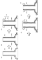
- FIG. 3 is a manufacturing process diagram of the tubular shaft 40 (including a manufacturing process of the tubular molded body 66)
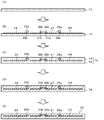
- FIG. 4 is a manufacturing process diagram of the plate 20
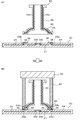
- FIG. 5 is an explanation showing a joining process of the plate 20 and the tubular shaft 40. It is a figure.
- a tubular molded body 66 is produced.
- the first molded body 62 for manufacturing the inner wall of the tubular shaft 40 is manufactured by mold casting molding, and the grooves 62a, 62b for arranging the feeding members 54a, 54b are provided on the outer surface of the first molded body 62. This is provided (see FIG. 3 (A)).
- Mold casting molding is a method sometimes called gel casting molding, and the details thereof are disclosed in, for example, Japanese Patent No. 5458050.
- a ceramic slurry containing a ceramic powder, a solvent, a dispersant and a gelling agent is poured into a first molding mold having an internal space having the same shape as that of the first molded body 62, and the gelling agent is chemically reacted.
- the ceramic slurry is gelled and then released from the mold to obtain a first molded product 62.
- the solvent is not particularly limited as long as it dissolves the dispersant and the gelling agent, but may be a polybasic acid ester (for example, dimethyl glutarate, etc.), a polyhydric alcohol acid ester (for example, triacetin, etc.), or the like. It is preferable to use a solvent having two or more ester bonds.
- the dispersant is not particularly limited as long as it uniformly disperses the ceramic powder in the solvent, but it is preferable to use a polycarboxylic acid-based copolymer, a polycarboxylic acid salt, or the like.
- a polycarboxylic acid-based copolymer for example, polyethylene glycol dimethacrylate (TDI), diphenylmethane diisocyanate (MDI), and modified products thereof.
- TDI tolylene diisocyanate
- MDI diphenylmethane diisocyanate
- the polyols are not particularly limited as long as they are substances having two or more hydroxyl groups capable of reacting with isocyanate groups, and for example, ethylene glycol (EG), polyethylene glycol (PEG), propylene glycol (PG), polypropylene glycol (PPG). And so on.
- the catalyst is not particularly limited as long as it is a substance that promotes the urethane reaction between isocyanates and polyols, and examples thereof include triethylenediamine, hexanediamine, and 6-dimethylamino-1-hexanol.
- the gelation reaction is a reaction in which isocyanates and polyols undergo a urethane reaction to form a urethane resin (polyurethane).
- the ceramic slurry due to the reaction of the gelling agent, and the urethane resin functions as an organic binder.
- the feeding members 54a and 54b processed in advance so as to have the shape shown in FIG. 2 are fitted into the grooves 62a and 62b of the first molded body 62 (see FIG. 3B). As a result, the feeding members 54a and 54b are in a state of crawling on the outer surface of the first molded body 62 in the vertical direction.
- a second molded body 64 for manufacturing the outer wall of the tubular shaft 40 is manufactured on the outer surface of the first molded body 62 by mold casting molding to obtain a tubular molded body 66 (see FIG. 3C). ).
- the same ceramic slurry as before is poured into the remaining internal space, and the gelling agent is chemically reacted.
- the ceramic slurry is gelled and then released from the mold to obtain a tubular molded product 66.
- the tubular molded body 66 has a second molded body 64 formed on the outside of the first molded body 62.
- the feeding members 54a and 54b are not exposed from the upper and lower ends of the tubular molded body 66 and are buried in the tubular molded body 66.
- Step (b) The tubular molded body 66 is dried, degreased, and then fired to obtain a tubular molded body 68 (see FIG. 3D). Drying is performed to evaporate the solvent contained in the tubular molded product 66.
- the drying temperature and drying time may be appropriately set according to the solvent used. However, the drying temperature is carefully set so that the tubular molded body 66 being dried does not crack. Degreasing after drying is performed to decompose and remove organic substances such as dispersants and catalysts contained in the tubular molded product 66.
- the degreasing temperature may be appropriately set according to the type of organic matter contained, but may be set to, for example, 400 to 600 ° C.
- the firing after degreasing is performed to sinter the ceramic particles contained in the tubular molded body 66.
- the firing temperature may be appropriately set depending on the type and particle size of the ceramic powder, but is preferably set in the range of 1000 to 2000 ° C.
- the atmosphere may be appropriately selected from the atmospheric atmosphere, the inert atmosphere, and the vacuum atmosphere according to the type of the ceramic powder.
- the ceramic powder is aluminum nitride powder, it is preferable to carry out drying, degreasing and firing in an inert atmosphere.
- the upper and lower ends of the tubular fired body 68 are ground to expose the upper and lower ends of the feeding members 54a and 54b to obtain the tubular shaft 40 (see FIG. 3E).
- the feeding members 54a and 54b are embedded in the tubular molded body 66 by using mold casting molding and then fired to obtain the tubular shaft 40. Therefore, the feeding members 54a and 54b are made of the ceramic material of the tubular shaft 40. In close contact.
- Step (c) The plate 20 is prepared by the procedure of FIGS. 4A to 4E.
- a disk-shaped first molded body 72 for producing a portion of the plate 20 on the wafer mounting surface 20a side is produced by mold casting (see FIG. 4A).
- the same ceramic slurry as in step (a) is poured into a molding die having an internal space having the same shape as that of the first molded body 72, and the gelling agent is chemically reacted to gel the ceramic slurry and then released.
- the first molded body 72 is obtained.
- the inner peripheral side resistance heating element 21 and the outer peripheral side resistance heating element 24 are arranged on the surface of the first molded body 72, and the connection terminals 22a and 22b are arranged at both ends 21a and 21b of the inner peripheral side resistance heating element 21, respectively. Then, the connection terminals 25a and 25b are arranged at both ends 24a and 24b of the outer peripheral side resistance heating element 24 (see FIG. 4B).
- a disk-shaped second molded body 74 for producing a portion on the joint surface side of the plate 20 is produced on the surface of the first molded body 72 by mold casting molding to obtain a disk-shaped molded body 76 (FIG. FIG. 4 (C)).
- the same ceramic slurry as before is poured into the remaining internal space. Then, the ceramic slurry is gelled by chemically reacting the gelling agent and then released from the mold to obtain a disk-shaped molded product 76.
- the disk-shaped molded body 76 is formed by laminating a second molded body 74 on the surface of the first molded body 72, and has inner peripheral side and outer peripheral side resistance heating elements 21, 24 and connection terminals 22a, 22b, 25a, 25b. Is built-in.
- the disk-shaped molded body 76 is dried, degreased, and then fired to obtain a disk-shaped fired body 78 (see FIG. 4 (D)). Drying, degreasing, and firing are performed in the same manner as when the tubular molded body 68 is obtained from the tubular molded body 66. Subsequently, the surface of the disk-shaped fired body 78 is ground to expose the connection terminals 25a and 25b to obtain the plate 20 (see FIG. 4E). At this stage, the connection terminals 22a and 22b remain embedded in the plate 20.
- Step (d) The plate 20 obtained in the step (c) and the tubular shaft 40 obtained in the step (b) are joined.
- a metal paste 34 is applied as a metal bonding material to the connection terminals 25a and 25b exposed on the surface of the plate 20, and a ceramic bonding material 35 is applied around the applied metal paste 34. Is applied.
- the metal contained in the metal paste 34 the same metals as those of the inner peripheral side and outer peripheral side resistance heating elements 21 and 24 may be used.
- the ceramic bonding material 35 include a solution of a bonding aid used in solid phase bonding (for example, an aqueous solution of yttrium nitrate).
- the tubular shaft 40 is placed on the plate 20 so that the plate 20 and the tubular shaft 40 are coaxial with each other.
- the portion of the feeding members 54a and 54b that is exposed from the end face of the outward flange 46 is brought into contact with the metal paste 34.
- the end surface of the outward flange 46 is brought into contact with the ceramic joint material 35.
- the metal paste 34 is arranged between the ends of the power feeding members 54a and 54b and the connection terminals 25a and 25b, and the ceramic bonding material 35 is arranged between the end surface of the tubular shaft 40 and the surface of the plate 20. It becomes a state.
- the pressure cylinder 80 is inserted into the tubular shaft 40, the pressure cylinder 80 is placed on the outward flange 46 of the tubular shaft 40, and the weight 82 is further placed on the pressure cylinder 80.
- This is installed in a heating furnace (not shown), the temperature is raised to a predetermined high temperature (for example, 1800 to 2000 ° C.) under an inert gas atmosphere, the temperature is maintained at that temperature for a predetermined time, and then the temperature is lowered.
- the outward flange 46 of the tubular shaft 40 is heated in a state of being pressed against the plate 20 by the weight 82, so that the ceramics of the outward flange 46 and the tubular shaft 40 are solid-phase bonded to each other.
- the feeding members 54a and 54b exposed on the end faces of the outward flange 46 are joined to the connection terminals 25a and 25b via a metal layer formed by solidifying the metal paste 34.
- connection terminals 22a and 22b are formed on the surface of the plate 20 at positions facing the connection terminals 22a and 22b, and the end faces of the connection terminals 22a and 22b are exposed on the bottom surfaces of the circular holes 23a and 23b.
- the power feeding members 51a and 51b are electrically connected to the connection terminals 22a and 22b via a brazing material or the like to obtain the ceramic heater 10 of FIG.
- the feeding members 54a and 54b are embedded in the peripheral wall portion of the tubular shaft 40 and are in close contact with the ceramic material of the tubular shaft 40. Therefore, even if stress acts on the feeding members 54a and 54b, the feeding members 54a and 54b do not sway in the peripheral wall portion of the tubular shaft 40, and the bonding between the feeding members 54a and 54b and the outer peripheral side resistance heating element 24 is formed. Secured.
- the tubular shaft 40 has an outward flange 46 at the upper end, and the feeding members 54a and 54b are electrically connected to the outer peripheral side resistance heating element 24 through the outward flange 46. Therefore, when the outward flange 46 of the tubular shaft 40 is pressed against the plate 20 during the manufacture of the ceramic heater 10, the power feeding members 54a and 54b are simultaneously pressed against the connection terminals 25a and 25b of the outer peripheral side resistance heating element 24. .. Therefore, the tubular shaft 40 and the plate 20 can be joined while ensuring the continuity between the power feeding members 54a and 54b and the connection terminals 25a and 25b.
- the tubular shaft 40 has a small diameter portion 42 from the lower end to a predetermined height and an enlarged diameter portion 44 having a larger diameter than the small diameter portion 42 from the predetermined height to the upper end, the tubular shaft 40 has a straight shape. The distance from the upper end to the lower end becomes longer, and the heat of the plate 20 is less likely to be transferred to the lower end of the tubular shaft 40. Therefore, when the lower end of the tubular shaft 40 is connected to another member via an O-ring (not shown), it is possible to prevent the O-ring from being deteriorated by heat.
- the inner peripheral side resistance heating element 21 is arranged in the inner peripheral zone Z1 of the plate 20, and the outer peripheral side resistance heating element 24 is arranged in the outer peripheral zone Z2 of the plate 20 and is embedded in the peripheral wall portion of the tubular shaft 40.
- the feeding members 54a and 54b are electrically connected to the outer peripheral side resistance heating element 24. That is, the feeding members 54a and 54b connected to the outer peripheral side resistance heating element 24 are not arranged in the internal space of the tubular shaft 40. Therefore, the internal space of the tubular shaft 40 can be used for another purpose.
- the internal space of the tubular shaft 40 is used to arrange the feeding members 51a and 51b connected to the inner peripheral side resistance heating element 21.
- connection terminals 22a and 22b are located on the bottom surfaces of the circular holes 23a and 23b provided on the lower surface of the plate 20, and such a structure is used when joining the tubular shaft 40 and the plate 20.
- the connection terminals 22a and 22b are left embedded in the plate 20, and after joining, circular holes 23a and 23b are provided on the lower surface 20b of the plate 20 to expose the connection terminals 22a and 22b on the bottom surfaces of the circular holes 23a and 23b. It is suitable for adopting the manufacturing method. By doing so, it is possible to prevent the connection terminals 22a and 22b from being denatured when the tubular shaft 40 and the plate 20 are joined.
- the tubular shaft 40 of FIG. 2 has a small diameter portion 42 from the lower end to a predetermined height, and an enlarged diameter portion 44 having a larger diameter than the small diameter portion 42 from the predetermined height to the upper end. is there. Therefore, even if the outer peripheral zone Z2 is divided into a plurality of small zones and the outer peripheral side resistance heating element is provided for each small zone, the power feeding member can be relatively easily connected to the outer peripheral side resistance heating element.
- a tubular shaft 40 having a diameter-expanded portion 44 and a straight-shaped tubular shaft when the same number of feeding members are embedded in the peripheral wall portion of the tubular shaft, the feeding members exposed at the upper end of the tubular shaft are connected to each other.
- the interval is easier to widen in the former than in the latter. Therefore, the distance between the terminals of the outer peripheral side resistance heating element can be widened, and the power feeding member can be relatively easily connected to the outer peripheral side resistance heating element.
- a pair of power feeding members is required for each outer peripheral side resistance heating element.
- the feeding members 54a and 54b embedded in the tubular shaft 40 pass through the outward flange 46, but may not pass through the outward flange 46 as shown in FIG. Further, one of the feeding members 54a and 54b may pass through the outward flange 46, and the other may not pass through the outward flange 46.
- TCB bonding Thermal compression bonding
- a hole is formed from the lower surface of the outward flange 46 toward the non-conducting portion. After making a hole and injecting a brazing material into the hole to ensure continuity, the ceramic powder may be sprayed to close the hole.
- tubular shaft 40 having the small diameter portion 42 and the enlarged diameter portion 44 is illustrated, but the tubular shaft 40 may have a straight shape.
- the plate 20 may have a built-in electrostatic electrode or an RF electrode.
- the electrostatic electrode is an electrode used to attract the wafer to the wafer mounting surface 20a
- the RF electrode is an electrode used to generate plasma.
- the present invention can be used, for example, in a semiconductor manufacturing apparatus.
Landscapes
- Chemical & Material Sciences (AREA)
- Engineering & Computer Science (AREA)
- Ceramic Engineering (AREA)
- Manufacturing & Machinery (AREA)
- Materials Engineering (AREA)
- Structural Engineering (AREA)
- Organic Chemistry (AREA)
- Inorganic Chemistry (AREA)
- Resistance Heating (AREA)
- Ceramic Products (AREA)
- Container, Conveyance, Adherence, Positioning, Of Wafer (AREA)
Abstract
Description
上面にウエハ載置面が設けられ内部に抵抗発熱体が埋設されたセラミック製のプレートと、
前記プレートの下面に接合されたセラミック製の筒状シャフトと、
前記筒状シャフトの周壁部を上下方向に貫通して前記抵抗発熱体と電気的に接続された給電部材と、
を備え、
前記給電部材は、前記筒状シャフトの周壁部に埋設され、前記筒状シャフトのセラミック材料と密着している、
ものである。
(a)セラミック製の筒状シャフトの内壁を作製するための第1モールドキャスト成形体の外面に給電部材を上下方向に這わせた状態で、前記筒状シャフトの外壁を作製するための第2モールドキャスト成形体を前記第1モールドキャスト成形体の外面に配置することにより、筒状成形体を得る工程と、
(b)前記筒状成形体を焼成することにより前記筒状シャフトを得る工程と、
(c)抵抗発熱体が埋設されたセラミック製のプレートであって、前記抵抗発熱体の両端にそれぞれ接触する接続端子が前記プレートの接合面から露出したものを用意する工程と、
(d)前記筒状シャフトの接合面に前記給電部材を露出させ、前記給電部材と前記プレートの前記接続端子との間に金属接合材を配置すると共に、前記筒状シャフトの接合面と前記プレートの接合面との間にセラミック接合材を配置した状態で、前記プレートに前記筒状シャフトを押圧しつつ加熱することにより、前記プレートと前記筒状シャフトとを接合する工程と、
を含むものである。
筒状成形体66を作製する。まず、筒状シャフト40の内壁を作製するための第1成形体62をモールドキャスト成形で作製し、第1成形体62の外面に給電部材54a,54bを配置するための溝62a,62bを2本設ける(図3(A)参照)。モールドキャスト成形とは、ゲルキャスト成形と呼ばれることもある方法であり、その詳細は例えば特許第5458050号公報などに開示されている。モールドキャスト成形では、第1成形体62と同形状の内部空間を備えた第1成形型に、セラミック粉体、溶媒、分散剤及びゲル化剤を含むセラミックスラリーを流し込み、ゲル化剤を化学反応させてセラミックスラリーをゲル化させたあと離型することにより、第1成形体62を得る。溶媒としては、分散剤及びゲル化剤を溶解するものであれば、特に限定されないが、多塩基酸エステル(例えば、グルタル酸ジメチル等)、多価アルコールの酸エステル(例えば、トリアセチン等)等の、2以上のエステル結合を有する溶媒を使用することが好ましい。分散剤としては、セラミック粉体を溶媒中に均一に分散するものであれば、特に限定されないが、ポリカルボン酸系共重合体、ポリカルボン酸塩等を使用することが好ましい。ゲル化剤としては、例えば、イソシアネート類、ポリオール類及び触媒を含むものとしてもよい。このうち、イソシアネート類としては、イソシアネート基を官能基として有する物質であれば特に限定されないが、例えば、トリレンジイソシアネート(TDI)、ジフェニルメタンジイソシアネート(MDI)又はこれらの変性体等が挙げられる。ポリオール類としては、イソシアネート基と反応し得る水酸基を2以上有する物質であれば特に限定されないが、例えば、エチレングリコール(EG)、ポリエチレングリコール(PEG)、プロピレングリコール(PG)、ポリプロピレングリコール(PPG)等が挙げられる。触媒としては、イソシアネート類とポリオール類とのウレタン反応を促進させる物質であれば特に限定されないが、例えば、トリエチレンジアミン、ヘキサンジアミン、6-ジメチルアミノ-1-ヘキサノール等が挙げられる。ここでは、ゲル化反応とは、イソシアネート類とポリオール類とがウレタン反応を起こしてウレタン樹脂(ポリウレタン)になる反応である。ゲル化剤の反応によりセラミックスラリーがゲル化し、ウレタン樹脂は有機バインダーとして機能する。
筒状成形体66を乾燥、脱脂したあと焼成することにより、筒状焼成体68を得る(図3(D)参照)。乾燥は、筒状成形体66に含まれる溶媒を蒸発させるために行う。乾燥温度や乾燥時間は、使用する溶媒に応じて適宜設定すればよい。但し、乾燥温度は、乾燥中の筒状成形体66にクラックが入らないように注意して設定する。乾燥後の脱脂は、筒状成形体66に含まれる分散剤や触媒などの有機物を分解・除去するために行う。脱脂温度は、含まれる有機物の種類に応じて適宜設定すればよいが、例えば400~600℃に設定してもよい。脱脂後の焼成は、筒状成形体66に含まれるセラミック粒子を焼結させるために行う。焼成温度は、セラミック粉末の種類、粒径などにより適宜設定すればよいが、1000~2000℃の範囲に設定することが好ましい。なお、雰囲気は、大気雰囲気、不活性雰囲気、真空雰囲気の中から、セラミック粉末の種類に応じて適宜選択すればよい。例えば、セラミック粉末が窒化アルミニウム粉末の場合には、不活性雰囲気で乾燥、脱脂、焼成を行うことが好ましい。続いて、筒状焼成体68の上端及び下端を研削して給電部材54a,54bの上端及び下端を露出させることにより、筒状シャフト40を得る(図3(E)参照)。このようにモールドキャスト成形を利用して筒状成形体66に給電部材54a,54bを埋設したあと焼成して筒状シャフト40を得るため、給電部材54a,54bは筒状シャフト40のセラミック材料と密着する。
プレート20を図4(A)~(E)の手順で作製する。まず、プレート20のウエハ載置面20a側の部分を作製するための円盤状の第1成形体72をモールドキャスト成形で作製する(図4(A)参照)。ここでは、第1成形体72と同形状の内部空間を備えた成形型に、工程(a)と同様のセラミックスラリーを流し込み、ゲル化剤を化学反応させてセラミックスラリーをゲル化させたあと離型することにより、第1成形体72を得る。
工程(c)で得られたプレート20と、工程(b)で得られた筒状シャフト40とを接合する。まず、図5(A)に示すように、プレート20の表面に露出している接続端子25a,25bに金属接合材として金属ペースト34を塗布し、塗布した金属ペースト34の周りにセラミック接合材35を塗布する。金属ペースト34に含まれる金属は、内周側及び外周側抵抗発熱体21,24と同じものを用いてもよい。セラミック接合材35としては、固相接合の際に用いられる接合助剤の溶液(例えば硝酸イットリウム水溶液など)が挙げられる。
Claims (10)
- 上面にウエハ載置面が設けられ内部に抵抗発熱体が埋設されたセラミック製のプレートと、
上端が前記プレートの下面に接合されたセラミック製の筒状シャフトと、
前記筒状シャフトの周壁部を上下方向に貫通して前記抵抗発熱体と電気的に接続された給電部材と、
を備え、
前記給電部材は、前記筒状シャフトの周壁部に埋設され、前記筒状シャフトのセラミック材料と密着している、
セラミックヒータ。 - 前記筒状シャフトは、上端に外向きフランジを有し、
前記給電部材は、前記外向きフランジを通って前記抵抗発熱体と電気的に接続されている、
請求項1に記載のセラミックヒータ。 - 前記筒状シャフトは、下端から所定の高さまでが小径部であり、前記所定の高さから前記上端までが前記小径部よりも径の大きな拡径部である、
請求項1又は2に記載のセラミックヒータ。 - 前記プレートは、前記プレートの内周ゾーンに配置された内周側抵抗発熱体と、前記プレートの外周ゾーンに配置された、前記抵抗発熱体としての外周側抵抗発熱体とを有している、
請求項1~3のいずれか1項に記載のセラミックヒータ。 - 前記内周側抵抗発熱体は、内周側接続端子を介して筒状シャフトの内部空間に配置された給電部材と電気的に接続され、
前記内周側接続端子の端面は、前記プレートの下面に設けられた穴の底面に位置している、
請求項4に記載のセラミックヒータ。 - (a)セラミック製の筒状シャフトの内壁を作製するための第1モールドキャスト成形体の外面に給電部材を上下方向に這わせた状態で、前記筒状シャフトの外壁を作製するための第2モールドキャスト成形体を前記第1モールドキャスト成形体の外面に配置することにより、筒状成形体を得る工程と、
(b)前記筒状成形体を焼成することにより前記筒状シャフトを得る工程と、
(c)抵抗発熱体が埋設されたセラミック製のプレートであって、前記抵抗発熱体の両端にそれぞれ接触する接続端子が前記プレートの接合面から露出したものを用意する工程と、
(d)前記筒状シャフトの接合面に前記給電部材を露出させ、前記給電部材と前記プレートの前記接続端子との間に金属接合材を配置すると共に、前記筒状シャフトの接合面と前記プレートの接合面との間にセラミック接合材を配置した状態で、前記プレートに前記筒状シャフトを押圧しつつ加熱することにより、前記プレートと前記筒状シャフトとを接合する工程と、
を含むセラミックヒータの製法。 - 前記工程(a)では、前記筒状成形体は、外向きフランジを有し、前記外向きフランジを前記給電部材が通過するように作製され、
前記工程(d)では、前記筒状シャフトの前記外向きフランジの端面に前記給電部材を露出させ、前記給電部材と前記接続端子との間に前記金属接合材を配置すると共に、前記外向きフランジの端面と前記プレートの接合面との間に前記セラミック接合材を配置した状態で、前記プレートに前記外向きフランジを押圧しつつ加熱することにより、前記プレートと前記筒状シャフトとを接合する、
請求項6に記載のセラミックヒータの製法。 - 前記筒状シャフトは、前記筒状シャフトの接合面とは反対側の端面から所定の高さまでが小径部であり、前記所定の高さから前記接合面までが前記小径部よりも径の大きな拡径部である、
請求項6又は7に記載のセラミックヒータの製法。 - 前記工程(c)では、前記プレートとして、前記プレートの内周ゾーンに内周側抵抗発熱体を有し、前記プレートの外周ゾーンに前記抵抗発熱体としての外周側抵抗発熱体を有するものを用意する、
請求項6~8のいずれか1項に記載のセラミックヒータの製法。 - 前記内周側抵抗発熱体は、内周側接続端子を介して前記筒状シャフトの内部空間に配置された給電部材と電気的に接続されるものであり、
前記工程(d)では、前記プレートと前記筒状プレートとを接合する際、前記内周側接続端子は前記プレートから露出せず前記プレートに埋設された状態であり、前記プレートと前記筒状プレートとの接合後、前記プレートに穴を設けて前記内周側接続端子の端面を前記穴の底面に露出させる、
請求項9に記載のセラミックヒータの製法。
Priority Applications (4)
| Application Number | Priority Date | Filing Date | Title |
|---|---|---|---|
| JP2021507165A JP7185762B2 (ja) | 2019-03-18 | 2020-03-03 | セラミックヒータ及びその製法 |
| CN202080021793.9A CN113632588B (zh) | 2019-03-18 | 2020-03-03 | 陶瓷加热器及其制法 |
| KR1020217025405A KR102628367B1 (ko) | 2019-03-18 | 2020-03-03 | 세라믹 히터 및 그의 제법 |
| US17/444,753 US12267919B2 (en) | 2019-03-18 | 2021-08-10 | Ceramic heater and method of manufacturing the same |
Applications Claiming Priority (2)
| Application Number | Priority Date | Filing Date | Title |
|---|---|---|---|
| JP2019-050231 | 2019-03-18 | ||
| JP2019050231 | 2019-03-18 |
Related Child Applications (1)
| Application Number | Title | Priority Date | Filing Date |
|---|---|---|---|
| US17/444,753 Continuation US12267919B2 (en) | 2019-03-18 | 2021-08-10 | Ceramic heater and method of manufacturing the same |
Publications (1)
| Publication Number | Publication Date |
|---|---|
| WO2020189264A1 true WO2020189264A1 (ja) | 2020-09-24 |
Family
ID=72520230
Family Applications (1)
| Application Number | Title | Priority Date | Filing Date |
|---|---|---|---|
| PCT/JP2020/009002 Ceased WO2020189264A1 (ja) | 2019-03-18 | 2020-03-03 | セラミックヒータ及びその製法 |
Country Status (6)
| Country | Link |
|---|---|
| US (1) | US12267919B2 (ja) |
| JP (1) | JP7185762B2 (ja) |
| KR (1) | KR102628367B1 (ja) |
| CN (1) | CN113632588B (ja) |
| TW (1) | TWI814995B (ja) |
| WO (1) | WO2020189264A1 (ja) |
Citations (4)
| Publication number | Priority date | Publication date | Assignee | Title |
|---|---|---|---|---|
| JP2016536803A (ja) * | 2013-09-16 | 2016-11-24 | アプライド マテリアルズ インコーポレイテッドApplied Materials,Incorporated | 温度プロファイル制御装置を有する加熱基板支持体 |
| JP2017085087A (ja) * | 2015-10-30 | 2017-05-18 | 日本碍子株式会社 | 半導体製造装置用部材、その製法及びシャフト付きヒータ |
| JP2017162878A (ja) * | 2016-03-07 | 2017-09-14 | 日本特殊陶業株式会社 | 基板支持装置 |
| JP2017183609A (ja) * | 2016-03-31 | 2017-10-05 | 日本特殊陶業株式会社 | 基板保持装置及びその製造方法 |
Family Cites Families (18)
| Publication number | Priority date | Publication date | Assignee | Title |
|---|---|---|---|---|
| DE69432383D1 (de) * | 1993-05-27 | 2003-05-08 | Applied Materials Inc | Verbesserungen betreffend Substrathalter geeignet für den Gebrauch in Vorrichtungen für die chemische Abscheidung aus der Dampfphase |
| CN1460094A (zh) * | 2001-04-12 | 2003-12-03 | 揖斐电株式会社 | 陶瓷接合体、其制造方法以及半导体晶片用陶瓷结构体 |
| JP3909248B2 (ja) * | 2002-01-28 | 2007-04-25 | 京セラ株式会社 | 試料加熱装置 |
| TWI281833B (en) * | 2004-10-28 | 2007-05-21 | Kyocera Corp | Heater, wafer heating apparatus and method for manufacturing heater |
| TW200633947A (en) | 2005-02-16 | 2006-10-01 | Ngk Insulators Ltd | Joined body and manufacturing method for the same |
| JP4435742B2 (ja) | 2005-08-09 | 2010-03-24 | 信越化学工業株式会社 | 加熱素子 |
| JP5087416B2 (ja) * | 2008-01-24 | 2012-12-05 | 日本碍子株式会社 | セラミックスヒータ及びその製造方法 |
| JP5202175B2 (ja) * | 2008-08-07 | 2013-06-05 | 日本碍子株式会社 | シャフト付きヒータ |
| JP5261103B2 (ja) * | 2008-09-26 | 2013-08-14 | 京セラ株式会社 | セラミックヒーター |
| JP5643062B2 (ja) * | 2009-11-24 | 2014-12-17 | 東京エレクトロン株式会社 | プラズマ処理装置 |
| KR101357928B1 (ko) * | 2010-09-24 | 2014-02-03 | 엔지케이 인슐레이터 엘티디 | 반도체 제조 장치 부재 |
| JP5855402B2 (ja) * | 2010-09-24 | 2016-02-09 | 日本碍子株式会社 | サセプター及びその製法 |
| US9706605B2 (en) * | 2012-03-30 | 2017-07-11 | Applied Materials, Inc. | Substrate support with feedthrough structure |
| JP6084906B2 (ja) * | 2013-07-11 | 2017-02-22 | 日本碍子株式会社 | セラミックヒータ |
| CN105282877B (zh) * | 2014-06-17 | 2019-10-25 | 住友电气工业株式会社 | 用于半导体制造装置的陶瓷加热器 |
| US10631370B2 (en) | 2015-10-30 | 2020-04-21 | Ngk Insulators, Ltd. | Member for semiconductor manufacturing apparatus, method for producing the same, and heater including shaft |
| WO2018030433A1 (ja) * | 2016-08-10 | 2018-02-15 | 日本碍子株式会社 | セラミックヒータ |
| US10840117B2 (en) * | 2016-09-12 | 2020-11-17 | Ngk Spark Plug Co., Ltd. | Holding apparatus |
-
2020
- 2020-03-03 CN CN202080021793.9A patent/CN113632588B/zh active Active
- 2020-03-03 KR KR1020217025405A patent/KR102628367B1/ko active Active
- 2020-03-03 WO PCT/JP2020/009002 patent/WO2020189264A1/ja not_active Ceased
- 2020-03-03 JP JP2021507165A patent/JP7185762B2/ja active Active
- 2020-03-09 TW TW109107656A patent/TWI814995B/zh active
-
2021
- 2021-08-10 US US17/444,753 patent/US12267919B2/en active Active
Patent Citations (4)
| Publication number | Priority date | Publication date | Assignee | Title |
|---|---|---|---|---|
| JP2016536803A (ja) * | 2013-09-16 | 2016-11-24 | アプライド マテリアルズ インコーポレイテッドApplied Materials,Incorporated | 温度プロファイル制御装置を有する加熱基板支持体 |
| JP2017085087A (ja) * | 2015-10-30 | 2017-05-18 | 日本碍子株式会社 | 半導体製造装置用部材、その製法及びシャフト付きヒータ |
| JP2017162878A (ja) * | 2016-03-07 | 2017-09-14 | 日本特殊陶業株式会社 | 基板支持装置 |
| JP2017183609A (ja) * | 2016-03-31 | 2017-10-05 | 日本特殊陶業株式会社 | 基板保持装置及びその製造方法 |
Also Published As
| Publication number | Publication date |
|---|---|
| US12267919B2 (en) | 2025-04-01 |
| JPWO2020189264A1 (ja) | 2021-12-09 |
| TW202040723A (zh) | 2020-11-01 |
| CN113632588B (zh) | 2024-06-25 |
| CN113632588A (zh) | 2021-11-09 |
| KR20210114446A (ko) | 2021-09-23 |
| KR102628367B1 (ko) | 2024-01-24 |
| JP7185762B2 (ja) | 2022-12-07 |
| US20210378061A1 (en) | 2021-12-02 |
| TWI814995B (zh) | 2023-09-11 |
Similar Documents
| Publication | Publication Date | Title |
|---|---|---|
| CN111837452B (zh) | 陶瓷加热器及其制法 | |
| TWI809204B (zh) | 半導體製造裝置用構件 | |
| CN105282877B (zh) | 用于半导体制造装置的陶瓷加热器 | |
| KR102368339B1 (ko) | 웨이퍼 지지대 | |
| US20200340102A1 (en) | Wafer holder | |
| TWI726253B (zh) | 半導體製造裝置用構件、其製法及成形模具 | |
| KR100634182B1 (ko) | 기판 가열 장치와 그 제조 방법 | |
| CN111755361B (zh) | 半导体制造装置用部件及其制造方法、成形模具 | |
| KR102739447B1 (ko) | 플러그, 플러그 제조 방법 및 반도체 제조 장치용 부재 | |
| CN212874436U (zh) | 一种陶瓷基座组件 | |
| US11195701B2 (en) | Showerhead | |
| JP6618409B2 (ja) | 基板保持装置及びその製造方法 | |
| JPWO2020189264A1 (ja) | セラミックヒータ及びその製法 | |
| CN104465453B (zh) | 等离子体cvd装置用的晶片加热器 | |
| JP7182083B2 (ja) | ウエハ保持体 | |
| JP2017147126A (ja) | セラミックスヒータの製造方法 | |
| TW202233010A (zh) | 陶瓷加熱器 | |
| JP2021017396A (ja) | 窒化アルミニウム焼結体、その製造方法、および窒化アルミニウム焼結体を用いた半導体製造装置用部品 | |
| JP2021125517A (ja) | セラミックヒータ | |
| JP7820211B2 (ja) | 電極埋設部材、および基板保持部材 | |
| JP2003249334A (ja) | セラミックスヒーターの製造方法 |
Legal Events
| Date | Code | Title | Description |
|---|---|---|---|
| 121 | Ep: the epo has been informed by wipo that ep was designated in this application |
Ref document number: 20774209 Country of ref document: EP Kind code of ref document: A1 |
|
| ENP | Entry into the national phase |
Ref document number: 2021507165 Country of ref document: JP Kind code of ref document: A |
|
| ENP | Entry into the national phase |
Ref document number: 20217025405 Country of ref document: KR Kind code of ref document: A |
|
| NENP | Non-entry into the national phase |
Ref country code: DE |
|
| 122 | Ep: pct application non-entry in european phase |
Ref document number: 20774209 Country of ref document: EP Kind code of ref document: A1 |