WO2020189010A1 - 基板処理方法、半導体製造方法、および、基板処理装置 - Google Patents
基板処理方法、半導体製造方法、および、基板処理装置 Download PDFInfo
- Publication number
- WO2020189010A1 WO2020189010A1 PCT/JP2020/002540 JP2020002540W WO2020189010A1 WO 2020189010 A1 WO2020189010 A1 WO 2020189010A1 JP 2020002540 W JP2020002540 W JP 2020002540W WO 2020189010 A1 WO2020189010 A1 WO 2020189010A1
- Authority
- WO
- WIPO (PCT)
- Prior art keywords
- structures
- substrate
- treatment
- liquid
- hydrophilicity
- Prior art date
- Legal status (The legal status is an assumption and is not a legal conclusion. Google has not performed a legal analysis and makes no representation as to the accuracy of the status listed.)
- Ceased
Links
Images



Classifications
-
- H—ELECTRICITY
- H10—SEMICONDUCTOR DEVICES; ELECTRIC SOLID-STATE DEVICES NOT OTHERWISE PROVIDED FOR
- H10P—GENERIC PROCESSES OR APPARATUS FOR THE MANUFACTURE OR TREATMENT OF DEVICES COVERED BY CLASS H10
- H10P72/00—Handling or holding of wafers, substrates or devices during manufacture or treatment thereof
- H10P72/04—Apparatus for manufacture or treatment
- H10P72/0402—Apparatus for fluid treatment
-
- H—ELECTRICITY
- H10—SEMICONDUCTOR DEVICES; ELECTRIC SOLID-STATE DEVICES NOT OTHERWISE PROVIDED FOR
- H10P—GENERIC PROCESSES OR APPARATUS FOR THE MANUFACTURE OR TREATMENT OF DEVICES COVERED BY CLASS H10
- H10P70/00—Cleaning of wafers, substrates or parts of devices
- H10P70/20—Cleaning during device manufacture
-
- H—ELECTRICITY
- H10—SEMICONDUCTOR DEVICES; ELECTRIC SOLID-STATE DEVICES NOT OTHERWISE PROVIDED FOR
- H10P—GENERIC PROCESSES OR APPARATUS FOR THE MANUFACTURE OR TREATMENT OF DEVICES COVERED BY CLASS H10
- H10P72/00—Handling or holding of wafers, substrates or devices during manufacture or treatment thereof
- H10P72/04—Apparatus for manufacture or treatment
- H10P72/0402—Apparatus for fluid treatment
- H10P72/0418—Apparatus for fluid treatment for etching
- H10P72/0422—Apparatus for fluid treatment for etching for wet etching
- H10P72/0424—Apparatus for fluid treatment for etching for wet etching using mainly spraying means, e.g. nozzles
-
- H—ELECTRICITY
- H10—SEMICONDUCTOR DEVICES; ELECTRIC SOLID-STATE DEVICES NOT OTHERWISE PROVIDED FOR
- H10P—GENERIC PROCESSES OR APPARATUS FOR THE MANUFACTURE OR TREATMENT OF DEVICES COVERED BY CLASS H10
- H10P50/00—Etching of wafers, substrates or parts of devices
-
- H—ELECTRICITY
- H10—SEMICONDUCTOR DEVICES; ELECTRIC SOLID-STATE DEVICES NOT OTHERWISE PROVIDED FOR
- H10P—GENERIC PROCESSES OR APPARATUS FOR THE MANUFACTURE OR TREATMENT OF DEVICES COVERED BY CLASS H10
- H10P52/00—Grinding, lapping or polishing of wafers, substrates or parts of devices
-
- H—ELECTRICITY
- H10—SEMICONDUCTOR DEVICES; ELECTRIC SOLID-STATE DEVICES NOT OTHERWISE PROVIDED FOR
- H10P—GENERIC PROCESSES OR APPARATUS FOR THE MANUFACTURE OR TREATMENT OF DEVICES COVERED BY CLASS H10
- H10P72/00—Handling or holding of wafers, substrates or devices during manufacture or treatment thereof
- H10P72/04—Apparatus for manufacture or treatment
- H10P72/0402—Apparatus for fluid treatment
- H10P72/0406—Apparatus for fluid treatment for cleaning followed by drying, rinsing, stripping, blasting or the like
-
- H—ELECTRICITY
- H10—SEMICONDUCTOR DEVICES; ELECTRIC SOLID-STATE DEVICES NOT OTHERWISE PROVIDED FOR
- H10P—GENERIC PROCESSES OR APPARATUS FOR THE MANUFACTURE OR TREATMENT OF DEVICES COVERED BY CLASS H10
- H10P72/00—Handling or holding of wafers, substrates or devices during manufacture or treatment thereof
- H10P72/04—Apparatus for manufacture or treatment
- H10P72/0402—Apparatus for fluid treatment
- H10P72/0406—Apparatus for fluid treatment for cleaning followed by drying, rinsing, stripping, blasting or the like
- H10P72/0408—Apparatus for fluid treatment for cleaning followed by drying, rinsing, stripping, blasting or the like for drying
-
- H—ELECTRICITY
- H10—SEMICONDUCTOR DEVICES; ELECTRIC SOLID-STATE DEVICES NOT OTHERWISE PROVIDED FOR
- H10P—GENERIC PROCESSES OR APPARATUS FOR THE MANUFACTURE OR TREATMENT OF DEVICES COVERED BY CLASS H10
- H10P72/00—Handling or holding of wafers, substrates or devices during manufacture or treatment thereof
- H10P72/04—Apparatus for manufacture or treatment
- H10P72/0402—Apparatus for fluid treatment
- H10P72/0406—Apparatus for fluid treatment for cleaning followed by drying, rinsing, stripping, blasting or the like
- H10P72/0411—Apparatus for fluid treatment for cleaning followed by drying, rinsing, stripping, blasting or the like for wet cleaning or washing
-
- H—ELECTRICITY
- H10—SEMICONDUCTOR DEVICES; ELECTRIC SOLID-STATE DEVICES NOT OTHERWISE PROVIDED FOR
- H10P—GENERIC PROCESSES OR APPARATUS FOR THE MANUFACTURE OR TREATMENT OF DEVICES COVERED BY CLASS H10
- H10P72/00—Handling or holding of wafers, substrates or devices during manufacture or treatment thereof
- H10P72/04—Apparatus for manufacture or treatment
- H10P72/0402—Apparatus for fluid treatment
- H10P72/0406—Apparatus for fluid treatment for cleaning followed by drying, rinsing, stripping, blasting or the like
- H10P72/0411—Apparatus for fluid treatment for cleaning followed by drying, rinsing, stripping, blasting or the like for wet cleaning or washing
- H10P72/0414—Apparatus for fluid treatment for cleaning followed by drying, rinsing, stripping, blasting or the like for wet cleaning or washing using mainly spraying means, e.g. nozzles
-
- H—ELECTRICITY
- H10—SEMICONDUCTOR DEVICES; ELECTRIC SOLID-STATE DEVICES NOT OTHERWISE PROVIDED FOR
- H10P—GENERIC PROCESSES OR APPARATUS FOR THE MANUFACTURE OR TREATMENT OF DEVICES COVERED BY CLASS H10
- H10P72/00—Handling or holding of wafers, substrates or devices during manufacture or treatment thereof
- H10P72/04—Apparatus for manufacture or treatment
- H10P72/0402—Apparatus for fluid treatment
- H10P72/0418—Apparatus for fluid treatment for etching
-
- H—ELECTRICITY
- H10—SEMICONDUCTOR DEVICES; ELECTRIC SOLID-STATE DEVICES NOT OTHERWISE PROVIDED FOR
- H10P—GENERIC PROCESSES OR APPARATUS FOR THE MANUFACTURE OR TREATMENT OF DEVICES COVERED BY CLASS H10
- H10P72/00—Handling or holding of wafers, substrates or devices during manufacture or treatment thereof
- H10P72/04—Apparatus for manufacture or treatment
- H10P72/0402—Apparatus for fluid treatment
- H10P72/0418—Apparatus for fluid treatment for etching
- H10P72/0421—Apparatus for fluid treatment for etching for drying etching
-
- H—ELECTRICITY
- H10—SEMICONDUCTOR DEVICES; ELECTRIC SOLID-STATE DEVICES NOT OTHERWISE PROVIDED FOR
- H10P—GENERIC PROCESSES OR APPARATUS FOR THE MANUFACTURE OR TREATMENT OF DEVICES COVERED BY CLASS H10
- H10P72/00—Handling or holding of wafers, substrates or devices during manufacture or treatment thereof
- H10P72/04—Apparatus for manufacture or treatment
- H10P72/0431—Apparatus for thermal treatment
- H10P72/0436—Apparatus for thermal treatment mainly by radiation
-
- H—ELECTRICITY
- H10—SEMICONDUCTOR DEVICES; ELECTRIC SOLID-STATE DEVICES NOT OTHERWISE PROVIDED FOR
- H10P—GENERIC PROCESSES OR APPARATUS FOR THE MANUFACTURE OR TREATMENT OF DEVICES COVERED BY CLASS H10
- H10P72/00—Handling or holding of wafers, substrates or devices during manufacture or treatment thereof
- H10P72/04—Apparatus for manufacture or treatment
- H10P72/0451—Apparatus for manufacturing or treating in a plurality of work-stations
-
- H—ELECTRICITY
- H10—SEMICONDUCTOR DEVICES; ELECTRIC SOLID-STATE DEVICES NOT OTHERWISE PROVIDED FOR
- H10P—GENERIC PROCESSES OR APPARATUS FOR THE MANUFACTURE OR TREATMENT OF DEVICES COVERED BY CLASS H10
- H10P72/00—Handling or holding of wafers, substrates or devices during manufacture or treatment thereof
- H10P72/04—Apparatus for manufacture or treatment
- H10P72/0451—Apparatus for manufacturing or treating in a plurality of work-stations
- H10P72/0452—Apparatus for manufacturing or treating in a plurality of work-stations characterised by the layout of the process chambers
-
- H—ELECTRICITY
- H10—SEMICONDUCTOR DEVICES; ELECTRIC SOLID-STATE DEVICES NOT OTHERWISE PROVIDED FOR
- H10P—GENERIC PROCESSES OR APPARATUS FOR THE MANUFACTURE OR TREATMENT OF DEVICES COVERED BY CLASS H10
- H10P72/00—Handling or holding of wafers, substrates or devices during manufacture or treatment thereof
- H10P72/04—Apparatus for manufacture or treatment
- H10P72/0451—Apparatus for manufacturing or treating in a plurality of work-stations
- H10P72/0462—Apparatus for manufacturing or treating in a plurality of work-stations characterised by the construction of the processing chambers, e.g. modular processing chambers
-
- H—ELECTRICITY
- H10—SEMICONDUCTOR DEVICES; ELECTRIC SOLID-STATE DEVICES NOT OTHERWISE PROVIDED FOR
- H10P—GENERIC PROCESSES OR APPARATUS FOR THE MANUFACTURE OR TREATMENT OF DEVICES COVERED BY CLASS H10
- H10P72/00—Handling or holding of wafers, substrates or devices during manufacture or treatment thereof
- H10P72/04—Apparatus for manufacture or treatment
- H10P72/0451—Apparatus for manufacturing or treating in a plurality of work-stations
- H10P72/0468—Apparatus for manufacturing or treating in a plurality of work-stations comprising a chamber adapted to a particular process
- H10P72/0471—Apparatus for manufacturing or treating in a plurality of work-stations comprising a chamber adapted to a particular process comprising at least one ion or electron beam chamber
Definitions
- the present invention relates to a substrate processing method, a semiconductor manufacturing method, and a substrate processing apparatus.
- the substrate processing apparatus described in Patent Document 1 removes organic substances from the substrate.
- a plurality of microstructures are formed on the surface of the substrate.
- the microstructure is formed in the process before the substrate is carried into the substrate processing apparatus. For example, by supplying a chemical solution to a substrate on which a resist pattern is formed and performing an etching process, a plurality of fine structures are formed on the surface of the substrate. Then, after the etching treatment, a rinsing treatment, a water repellent treatment, and a drying treatment are performed.
- the rinsing treatment is a treatment in which pure water is supplied to the substrate to wash away the chemical solution.
- the drying process is a process of drying the substrate by rotating the substrate in a horizontal plane. During drying, the microstructures can collapse due to the surface tension of pure water.
- Water repellent treatment is performed before the drying treatment in order to prevent the microstructure from collapsing.
- the water-repellent treatment is a treatment of supplying a treatment liquid containing a water-repellent agent to the surface of a substrate to form a water-repellent film (organic substance) on the surface of a microstructure.
- the water-repellent treatment can reduce the surface tension of pure water acting on the fine structure, and can suppress the collapse of the fine structure in the drying treatment.
- the water-repellent film (organic substance) is unnecessary as a semiconductor product. Therefore, it is desired to remove the water-repellent film (organic matter) after the drying treatment.
- the substrate processing apparatus irradiates the substrate with ultraviolet rays to remove the water-repellent film (organic matter). Specifically, ultraviolet rays act on the water-repellent film (organic substance) existing on the substrate, and the water-repellent film (organic substance) is decomposed and removed.
- the substrate is only irradiated with ultraviolet rays after etching to remove organic substances.
- the effect of ultraviolet rays does not affect the etching.
- the substrate is irradiated with ultraviolet rays after the treatment with the treatment liquid, the effect of the ultraviolet rays does not affect the treatment with the treatment liquid.
- the patterns formed on the substrate have been further miniaturized. That is, on the surface of the substrate, the space between the plurality of microstructures is further narrowed. Therefore, the surface tension (surface free energy) of the substrate may suppress the infiltration of the treatment liquid into the space between the plurality of microstructures. As a result, in the substrate, there may be a portion where the treatment liquid has sufficiently penetrated and a portion where the treatment liquid has not sufficiently penetrated. Therefore, there is a possibility that the treatment results of a plurality of fine structures with the treatment liquid may vary.
- the present invention has been made in view of the above problems, and an object of the present invention is a substrate processing method, a semiconductor manufacturing method, and a substrate that can promote the penetration of a treatment liquid into a space between a plurality of structures on a substrate.
- the purpose is to provide a processing device.
- a substrate having a pattern containing a plurality of structures is processed.
- the substrate treatment method includes a step of executing a predetermined treatment with a non-liquid on the plurality of structures to increase the hydrophilicity of the surface of each of the plurality of structures as compared with that before the execution of the predetermined treatment.
- a step of supplying the treatment liquid to the plurality of structures is included after the step of increasing the hydrophilicity.
- the substrate treatment method of the present invention further includes a step of supplying a removing liquid for removing oxides from the substrate to the plurality of structures before the step of increasing hydrophilicity.
- the predetermined treatment is a treatment of irradiating the plurality of structures with ultraviolet rays.
- the predetermined treatment is a treatment of irradiating the plurality of structures with plasma.
- the predetermined treatment is a treatment of supplying oxygen or an allotrope of oxygen to the plurality of structures.
- the processing liquid dissolves the gas existing in the space between the structures adjacent to each other among the plurality of structures.
- the hydrophobic agent is supplied to the plurality of structures after the step of supplying the treatment liquid, and the plurality of structures are more than before the supply of the hydrophobic agent. It is preferable to further include a step of increasing the hydrophobicity of each surface of the object and a step of drying the substrate after the step of increasing the hydrophobicity.
- the distance between the structures adjacent to each other among the plurality of structures satisfies a predetermined condition.
- the predetermined condition indicates that the same treatment liquid as the treatment liquid cannot permeate into the space between the structures adjacent to each other before the step of increasing the hydrophilicity.
- the predetermined conditions preferably include the first condition and the second condition.
- the first condition indicates that the same treatment liquid as the treatment liquid cannot permeate into the space between the structures adjacent to each other due to the capillary phenomenon before the step of increasing the hydrophilicity.
- the second condition shows that the treatment liquid can permeate into the space between the structures adjacent to each other by the capillary phenomenon after the step of increasing the hydrophilicity.
- the predetermined treatment is executed on the plurality of structures, and each of the plurality of structures is subjected to more than before the execution of the predetermined treatment. It is preferable to increase the hydrophilicity of the surface of the recess having the recess. It is preferable that the recess is recessed in a direction intersecting the side wall surface of the structure in a direction in which the structure extends.
- a semiconductor substrate having a pattern including a plurality of structures is processed to manufacture the semiconductor which is the processed semiconductor substrate.
- the semiconductor manufacturing method includes a step of executing a predetermined treatment with a non-liquid on the plurality of structures to increase the hydrophilicity of the surface of each of the plurality of structures as compared with that before the execution of the predetermined treatment.
- a step of supplying the treatment liquid to the plurality of structures is included after the step of increasing the hydrophilicity.
- the substrate processing apparatus processes a substrate having a pattern including a plurality of structures.
- the substrate processing apparatus includes a hydrophilic treatment unit and a processing liquid supply unit.
- the hydrophilic treatment unit executes a predetermined treatment with a non-liquid on the plurality of structures to make the surface hydrophilicity of each of the plurality of structures larger than before the execution of the predetermined treatment.
- the treatment liquid supply unit supplies the treatment liquid to the plurality of structures after the hydrophilicity of each surface of the plurality of structures is increased.
- the substrate processing apparatus of the present invention further includes a removing liquid supply unit. It is preferable that the removing liquid supply unit supplies the removing liquid for removing oxides from the substrate toward the plurality of structures before the hydrophilicity of each surface of the plurality of structures is increased. ..
- the predetermined treatment is preferably a treatment of irradiating the plurality of structures with ultraviolet rays.
- the predetermined processing is a processing of irradiating the plurality of structures with plasma.
- the predetermined treatment is a treatment of supplying oxygen or an allotrope of oxygen to the plurality of structures.
- the processing liquid dissolves the gas existing in the space between the structures adjacent to each other among the plurality of structures.
- the substrate processing apparatus of the present invention further includes a hydrophobic processing unit and a drying processing unit.
- the hydrophobic treatment unit supplies the hydrophobic agent to the plurality of structures after the treatment liquid is supplied to the plurality of structures, and is more than before the supply of the hydrophobic agent.
- the drying treatment unit dries the substrate after the hydrophobicity of the surface of each of the plurality of structures is increased.
- the distance between the structures adjacent to each other among the plurality of structures satisfies a predetermined condition.
- the predetermined condition may indicate that the same treatment liquid as the treatment liquid cannot permeate into the space between the structures adjacent to each other before the hydrophilicity of each surface of the plurality of structures is increased. preferable.
- the predetermined conditions preferably include the first condition and the second condition.
- the first condition before the hydrophilicity of each surface of the plurality of structures is increased, the same treatment liquid as the treatment liquid permeates into the space between the structures adjacent to each other depending on the capillary phenomenon. It is preferable to show that it cannot be done.
- the second condition indicates that the treatment liquid can permeate into the space between the structures adjacent to each other by the capillary phenomenon after the hydrophilicity of each surface of the plurality of structures is increased. ..
- the hydrophilic treatment unit executes the predetermined treatment on the plurality of structures, and has a recess in each of the plurality of structures than before the execution of the predetermined treatment. It is preferable to increase the hydrophilicity of the surface. It is preferable that the recess is recessed in a direction intersecting the side wall surface of the structure in a direction in which the structure extends.
- a substrate processing method capable of facilitating the penetration of a processing liquid into a space between a plurality of structures on a substrate.
- FIG. 1 It is a schematic plan view which shows the substrate processing apparatus which concerns on Embodiment 1 of this invention.
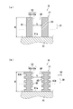
- A is a schematic cross-sectional view showing an example of the substrate according to the first embodiment.
- B is a schematic cross-sectional view showing another example of the substrate according to the first embodiment.
- It is a schematic cross-sectional view which shows the hydrophilic treatment apparatus which concerns on Embodiment 1.
- FIG. It is a schematic cross-sectional view which shows the processing apparatus which concerns on Embodiment 1.
- FIG. It is a graph which shows the relationship between the permeation time of the treatment liquid which concerns on Embodiment 1 and a contact angle.
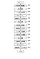
- It is a flowchart which shows the substrate processing method which concerns on Embodiment 1.
- FIG. It is a flowchart which shows the process S1 of FIG. It is a schematic plan view which shows the processing apparatus which concerns on the modification of Embodiment 1. It is a schematic cross-sectional view which shows the processing apparatus which concerns on Embodiment 2 of this invention. It is a schematic cross-sectional view which shows the hydrophilic treatment nozzle which concerns on Embodiment 2. FIG. It is a schematic cross-sectional view which shows the processing apparatus which concerns on Embodiment 3 of this invention. It is a schematic cross-sectional view which shows the processing apparatus which concerns on Embodiment 4 of this invention. It is a flowchart which shows the substrate processing method which concerns on Embodiment 4.
- the same or corresponding parts are designated by the same reference numerals and the description is not repeated.
- the X-axis, the Y-axis, and the Z-axis are orthogonal to each other, the X-axis and the Y-axis are parallel in the horizontal direction, and the Z-axis is parallel in the vertical direction.
- diagonal lines indicating the cross section are appropriately omitted.
- the substrate processing apparatus 100 processes the substrate W with the processing liquid.
- the treatment liquid will be referred to as "treatment liquid LQ".
- the substrate W includes, for example, a semiconductor wafer, a substrate for a liquid crystal display device, a substrate for a plasma display, a substrate for a field emission display (FED), an optical disk substrate, a magnetic disk substrate, a magneto-optical disk substrate, and a photomask. Substrates, ceramic substrates, or solar cell substrates.
- the substrate W has, for example, a substantially disk shape. In the following description of the first embodiment, the substrate W is a semiconductor substrate.
- FIG. 1 is a schematic plan view showing a substrate processing apparatus 100.
- the substrate processing device 100 includes an indexer unit U1, a processing unit U2, and a control device U3.
- the indexer unit U1 includes a plurality of substrate containers C and an indexer robot IR.
- the processing unit U2 includes a plurality of processing devices 200, a transfer robot CR, and a delivery unit PS.
- Each of the substrate container C accommodates a plurality of substrates W in a laminated manner.
- the indexer robot IR takes out the unprocessed substrate W from one of the plurality of substrate containers C and passes the substrate W to the delivery unit PS. Then, the substrate W taken out from the substrate container C is placed on the delivery portion PS.
- the transfer robot CR receives the unprocessed substrate W from the delivery unit PS, and carries the substrate W into one of the plurality of processing devices 200.
- the processing device 200 processes the unprocessed substrate W.
- the processing device 200 is a single-wafer type that processes the substrate W one by one.
- the processing apparatus 200 processes the substrate W with the processing liquid LQ.
- the transfer robot CR takes out the processed substrate W from the processing device 200 and passes the substrate W to the delivery unit PS. Then, the substrate W processed by the processing device 200 is placed on the delivery unit PS.
- the indexer robot IR receives the processed substrate W from the delivery unit PS, and accommodates the substrate W in any one of the plurality of substrate containers C.
- the control device U3 controls the indexer unit U1 and the processing unit U2.
- the control device U3 includes a computer.
- the control device U3 includes a processor such as a CPU (Central Processing Unit) and a storage device.
- the storage device stores data and computer programs.
- the storage device includes a main storage device such as a semiconductor memory and an auxiliary storage device such as a semiconductor memory and / or a hard disk drive.
- the storage device may include removable media.
- the processor of the control device U3 executes a computer program stored in the storage device of the control device U3 to control the indexer unit U1 and the processing unit U2.
- FIG. 2A is a schematic cross-sectional view showing an example of the substrate W.
- the substrate W has a substrate main body 61 and a pattern PT.
- the substrate body 61 is made of silicon.
- the pattern PT is, for example, a fine pattern.
- the pattern PT includes a plurality of structures 63.
- the structure 63 is, for example, a fine structure.
- Each of the plurality of structures 63 extends along the first direction D1.
- the first direction D1 indicates a direction that intersects the surface 61a of the substrate body 61.
- the first direction D1 indicates a direction substantially orthogonal to the surface 61a of the substrate body 61.
- the surface 62 of the structure 63 has a side wall surface 63a and a top wall surface 63b.
- Each of the plurality of structures 63 is composed of a single layer or a plurality of layers.
- the structure 63 is an insulating layer, a semiconductor layer, or a conductor layer.
- the structure 63 may include an insulating layer, a semiconductor layer, a conductor layer, an insulating layer, a semiconductor layer, and a conductor layer. Two or more of them may be included.
- the insulating layer is, for example, a silicon oxide film or a silicon nitride film.
- the semiconductor layer is, for example, a polysilicon film or an amorphous silicon film.
- the conductor layer is, for example, a metal film.
- the metal film is, for example, a film containing at least one of titanium, tungsten, copper, and aluminum.
- FIG. 2B is a schematic cross-sectional view showing another example of the substrate W.
- each of the plurality of structures 63 has at least one recess 65.
- each of the plurality of structures 63 has a plurality of recesses 65.
- Each of the plurality of recesses 65 is recessed with respect to the side wall surface 63a of the structure 63 along the direction in which the structure 63 intersects in the extending direction.
- the direction in which the structure 63 extends is substantially parallel to the first direction D1.
- each of the plurality of recesses 65 is recessed along the second direction D2.
- the second direction D2 indicates a direction along the surface 61a of the substrate main body 61. Specifically, the second direction D2 indicates a direction that intersects with the first direction D1. In the first embodiment, the second direction D2 indicates a direction substantially orthogonal to the first direction D1.
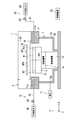
- FIG. 3 is a schematic cross-sectional view showing the hydrophilic treatment apparatus 1.
- the hydrophilic treatment device 1 corresponds to an example of the “hydrophilic treatment unit”.
- the hydrophilic treatment device 1 is installed, for example, in the delivery section PS shown in FIG.
- the installation position of the hydrophilic treatment device 1 is not particularly limited.
- the hydrophilic treatment device 1 may be included in the substrate processing device 100 instead of the processing device 200 of one of the plurality of processing devices 200 shown in FIG.
- the hydrophilic treatment device 1 executes a predetermined treatment with a non-liquid on the plurality of structures 63 of the substrate W, and makes the hydrophilicity of each surface 62 of the plurality of structures 63 larger than before the execution of the predetermined treatment.
- Hydrophilicity indicates the degree of ease with which a liquid adheres to a solid surface. The greater the hydrophilicity, the easier it is for the liquid to adhere to the solid surface. That is, the greater the hydrophilicity, the easier it is for the solid surface to get wet. Hydrophilicity can be represented by the contact angle CA.
- the contact angle CA is an angle formed by the liquid surface with the solid surface at the contact boundary of the three phases when the solid surface is in contact with the liquid and the gas.
- Non-liquid refers to electromagnetic waves or non-liquid substances.
- the “electromagnetic wave” is, for example, light.
- the “non-liquid substance” is, for example, plasma or gas.
- predetermined treatment means “predetermined treatment with non-liquid”.
- Predetermined treatment with non-liquid indicates “treatment using non-liquid”.
- the hydrophilic treatment apparatus 1 executes a predetermined treatment on the plurality of structures 63 of the substrate W before supplying the treatment liquid LQ to the substrate W, and executes the predetermined treatment.
- the hydrophilicity of each surface 62 of the plurality of structures 63 is made larger than before. Therefore, the surface tension of the surface 62 of the structure 63 can be made larger than that before the execution of the predetermined treatment.
- the substrate W is treated with the treatment liquid LQ, it is possible to promote the treatment liquid LQ from entering the space SP between the plurality of structures 63 in the substrate W.
- the treatment liquid LQ When the treatment liquid LQ can be promoted to penetrate into the space SP between the plurality of structures 63, the treatment liquid LQ is rapidly applied to the space SP between the plurality of structures 63 substantially uniformly over the entire substrate W. Can be infiltrated into. Therefore, it is possible to suppress the occurrence of variation in the treatment results of the plurality of structures 63 by the treatment liquid LQ.
- the treatment liquid LQ when the treatment liquid LQ is an etching liquid, it is possible to suppress the occurrence of variations in the etching results of the plurality of structures 63.
- the treatment liquid LQ can be rapidly permeated into the space SP between the plurality of structures 63, the plurality of structures 63 can be effectively treated by the treatment liquid LQ.
- the treatment liquid LQ is an etching liquid
- a plurality of structures 63 can be effectively etched.
- At least the hydrophilicity of the side wall surface 63a may be made larger than that before the execution of the predetermined treatment.
- the substrate W is dried before the execution of the predetermined treatment. “Drying” indicates that the liquid has been removed from the substrate W.
- the hydrophilic treatment apparatus 1 executes a predetermined treatment on the plurality of structures 63 before supplying the treatment liquid LQ to the substrate W.
- the hydrophilicity of the side wall surface 63a and the top wall surface 63b of each of the plurality of structures 63 and the hydrophilicity of the surface of the recess 65 of each of the plurality of structures 63 are increased as compared with those before the execution of the predetermined treatment. Therefore, when the substrate W is treated with the treatment liquid LQ, not only can the treatment liquid LQ be promoted to enter the space SP between the plurality of structures 63 in the substrate W, but also the treatment liquid LQ is formed in the plurality of recesses 65. It can promote infiltration into each of the. As a result, the treatment liquid LQ can be rapidly permeated into the recess 65, and the recess 65 can be effectively treated by the treatment liquid LQ.
- the surface 62 of the structure 63 shown in FIG. 2B includes the surface of the recess 65. Then, of the surface 62 of the structure 63, the hydrophilicity of the side wall surface 63a and the hydrophilicity of the surface of the recess 65 may be made larger than before the execution of the predetermined treatment.
- hydrophilicity of each surface 62 of the plurality of structures 63 as compared to before the execution of the predetermined treatment may be described as "hydrophilicization”. Further, “permeation” indicates that the treatment liquid LQ invades the space SP between the structures 63 and reaches the surface 61a or the vicinity of the surface 61a of the substrate main body 61.
- the predetermined treatment is a treatment of irradiating a plurality of structures 63 of the substrate W with ultraviolet rays. That is, the hydrophilic treatment device 1 irradiates the plurality of structures 63 of the substrate W with ultraviolet rays to make the hydrophilicity of each surface 62 of the plurality of structures 63 larger than that before the irradiation of the ultraviolet rays. Since the energy of ultraviolet rays is larger than the energy of visible light, the surface 62 of the structure 63 can be effectively hydrophilized.
- the hydrophilic treatment device 1 includes an ultraviolet irradiation unit 3, a substrate holding unit 5, an accommodating unit 7, a plurality of gas supply units 10, an exhaust unit 11, and a moving mechanism. 13 and a rotation mechanism 15 are included.
- the board holding portion 5 holds the board W. Specifically, the substrate holding portion 5 rotates the substrate W around the rotation axis AX1 of the substrate holding portion 5 while holding the substrate W horizontally.
- the rotation axis AX1 is substantially parallel in the vertical direction and passes through the center of the substrate W.
- the substrate holding portion 5 includes a spin base 51 and a plurality of chuck members 53.
- the plurality of chuck members 53 are provided on the spin base 51 along the circumferential direction around the rotation axis AX1.
- the plurality of chuck members 53 hold the substrate W in a horizontal posture.
- the spin base 51 has a substantially disc shape or a substantially columnar shape, and supports a plurality of chuck members 53 in a horizontal posture. When the spin base 51 rotates around the rotation axis AX1, the substrates W held by the plurality of chuck members 53 rotate around the rotation axis AX1.
- the moving mechanism 13 moves the substrate holding portion 5 along the vertical direction. Specifically, the moving mechanism 13 reciprocates the substrate holding portion 5 between the first position and the second position.
- the first position indicates a position where the substrate holding portion 5 is close to the ultraviolet irradiation portion 3. In FIG. 2, the substrate holding portion 5 located at the first position is illustrated.
- the second position indicates a position where the substrate holding portion 5 is far from the ultraviolet irradiation portion 3.
- the first position is the position of the substrate holding portion 5 when the processing using ultraviolet rays is performed on the substrate W.
- the second position is the position of the substrate holding portion 5 when the substrate W is transferred.
- the moving mechanism 13 includes, for example, a ball screw mechanism.
- the rotation mechanism 15 rotates the substrate holding portion 5 around the rotation axis AX1. As a result, the substrate W held by the substrate holding portion 5 rotates around the rotation axis AX1.
- the rotation mechanism 15 includes, for example, a motor.
- the ultraviolet irradiation unit 3 and the substrate holding unit 5 are arranged along the rotation axis AX1 and face each other.
- the ultraviolet irradiation unit 3 faces the substrate W with a spatial SPA.
- the ultraviolet irradiation unit 3 generates ultraviolet rays.
- the space SPA is a space between the ultraviolet irradiation unit 3 and the substrate holding unit 5.
- the ultraviolet irradiation unit 3 irradiates the surfaces 62 of the plurality of structures 63 of the substrate W with ultraviolet rays to make the hydrophilicity of each surface 62 of the plurality of structures 63 larger than that before the irradiation of the ultraviolet rays. It is considered that the reason why the hydrophilicity is increased is that the oxidation of the surface 62 of the structure 63 is promoted by the irradiation of ultraviolet rays.
- the ultraviolet irradiation unit 3 irradiates the surfaces 62 of the plurality of structures 63 of the substrate W with ultraviolet rays while the substrate W is rotating. Therefore, the ultraviolet rays can be more uniformly irradiated to the surfaces 62 of the plurality of structures 63 of the substrate W as compared with the case where the stationary substrate W is irradiated with the ultraviolet rays. As a result, the hydrophilicity of each surface 62 of the plurality of structures 63 of the substrate W can be effectively increased as compared with that before irradiation with ultraviolet rays.
- the ultraviolet irradiation unit 3 includes an electrode 33, an electrode 35, and a quartz glass plate 31.
- the electrode 33 has a substantially flat plate shape.
- the electrode 35 has a substantially flat plate shape.
- the electrode 35 has a plurality of openings 351. Each of the openings 351 penetrates the electrode 35 in the vertical direction.
- the electrode 35 faces the electrode 33 with a space in between.
- the electrode 35 is located on the quartz glass plate 31 side with respect to the electrode 33.
- the quartz glass plate 31 is provided on the substrate W side.
- the quartz glass plate 31 has translucency against ultraviolet rays, and has heat resistance and corrosion resistance.
- the quartz glass plate 31 is an insulator.
- Discharge gas exists in the space between the electrode 33 and the electrode 35. Then, a high voltage having a high frequency is applied between the electrode 33 and the electrode 35. As a result, the discharge gas is excited and becomes an excimer state. The discharge gas generates ultraviolet rays when returning from the excimer state to the ground state. Ultraviolet rays pass through the opening 351 of the electrode 35, further pass through the quartz glass plate 31, and irradiate the substrate W.
- the hydrophilic treatment device 1 includes a high voltage power supply that applies a high voltage of a high frequency between the electrode 33 and the electrode 35. Further, as long as the ultraviolet irradiation unit 3 can irradiate ultraviolet rays, the configuration and shape of the ultraviolet irradiation unit 3 are not particularly limited.
- the accommodating portion 7 accommodates the substrate holding portion 5, the moving mechanism 13, and the rotating mechanism 15. Then, the ultraviolet irradiation unit 3 closes the upper opening of the accommodating unit 7. Therefore, the ultraviolet irradiation unit 3 and the accommodating unit 7 function as a chamber.
- the accommodating portion 7 includes a tubular portion 71, a side wall portion 73, and a bottom portion 75.
- the lower part of the tubular portion 71 and the upper part of the side wall portion 73 are connected.
- the lower part of the side wall portion 73 and the bottom portion 75 are connected.
- the tubular portion 71 has a plurality of through holes 71a. Each of the through holes 71a penetrates the tubular portion 71 and communicates with the space SPA.
- the side wall portion 73 has a through hole 73a.
- the through hole 73a penetrates the side wall portion 73.
- each of the gas supply units 10 supplies the inert gas to the space SPA through the through hole 71a.
- the inert gas is, for example, nitrogen or argon.
- each of the gas supply units 10 includes a pipe 91, an on-off valve 93, and a gas reservoir 95.
- the gas container 95 contains the inert gas supplied to the space SPA.
- the gas container 95 is connected to one end of the pipe 91.
- the on-off valve 93 is provided in the pipe 91 to switch the opening and closing of the pipe 91.
- the other end of the pipe 91 is connected to the through hole 91a.
- the exhaust unit 11 exhausts the gas inside the accommodating unit 7 from the through hole 73a.
- the control device U3 controls the hydrophilic treatment device 1. Specifically, the processor of the control device U3 executes a computer program stored in the storage device of the control device U3 to control the hydrophilic treatment device 1.
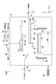
- FIG. 4 is a schematic cross-sectional view showing the processing apparatus 200.
- the processing apparatus 200 rotates the substrate W after the hydrophilicity of each surface 62 of the plurality of structures 63 of the substrate W is increased by the hydrophilic treatment apparatus 1.
- the processing liquid LQ is supplied to W to process the substrate W.
- the processing device 200 includes a chamber 21, a spin chuck 23, a spin shaft 24, a spin motor 25, a nozzle 27, a nozzle moving portion 29, a nozzle 30, a plurality of guards 49, and a valve. It includes V1, a valve V2, a pipe P1, and a pipe P2.
- Chamber 21 has a substantially box shape.
- the chamber 21 accommodates the substrate W, the spin chuck 23, the spin shaft 24, the spin motor 25, the nozzle 27, the nozzle moving portion 29, the nozzle 30, a part of the pipe P1, and a part of the pipe P2.
- the spin chuck 23 holds the substrate W and rotates. Specifically, the spin chuck 23 rotates the substrate W around the rotation axis AX2 of the spin chuck 23 while holding the substrate W horizontally in the chamber 21.
- the spin chuck 23 includes a plurality of chuck members 231 and a spin base 233.
- the plurality of chuck members 231 are provided on the spin base 233.
- the plurality of chuck members 231 hold the substrate W in a horizontal posture.
- the spin base 233 has a substantially disk shape and supports a plurality of chuck members 231 in a horizontal posture.
- the spin shaft 24 is fixed to the spin base 233. Further, the spin shaft 24 is fixed to the drive shaft of the spin motor 25. Then, the spin motor 25 rotates the spin shaft 24 to rotate the spin base 233 around the rotation axis AX2. As a result, the substrate W held by the plurality of chuck members 231 provided on the spin base 233 rotates around the rotation axis AX2.
- the nozzle 27 is directed toward the plurality of structures 63 of the rotating substrate W after the hydrophilicity of each surface 62 of the plurality of structures 63 of the substrate W is increased by the hydrophilic treatment apparatus 1.
- Supply LQ Therefore, the treatment liquid LQ can be effectively permeated into the space SP between the plurality of structures 63 of the substrate W. As a result, the structure 63 can be effectively treated by the treatment liquid LQ.
- the nozzle 27 corresponds to an example of a “treatment liquid supply unit”.
- the treatment liquid LQ dissolves the gas existing in the space SP between the structures 63 adjacent to each other among the plurality of structures 63.
- the treatment liquid LQ can be more quickly permeated into the space SP between the plurality of structures 63 of the substrate W.
- the treatment liquid LQ is, for example, a chemical liquid (for example, an etching liquid).
- the chemicals are, for example, hydrofluoric acid (HF), hydrofluoric acid (mixture of hydrofluoric acid and nitric acid (HNO 3 )), buffered hydrofluoric acid (BHF), ammonium fluoride, HFEG (mixture of hydrofluoric acid and ethylene glycol).
- the type of the treatment liquid LQ is not particularly limited as long as the substrate W can be treated.
- the nozzle moving unit 29 moves the nozzle 27 between the processing position and the retracted position.
- the processing position indicates a position above the substrate W.
- the processing liquid LQ is supplied to the surfaces 62 of the plurality of structures 63 of the substrate W.
- the retracted position indicates a position on the radial side of the substrate W with respect to the substrate W.
- the nozzle moving unit 29 includes an arm 291, a rotating shaft 293, and a nozzle moving mechanism 295.
- the arm 291 extends along a substantially horizontal direction.
- a nozzle 27 is attached to the tip of the arm 291.
- the arm 291 is coupled to the rotation shaft 293.
- the rotation shaft 293 extends along a substantially vertical direction.
- the nozzle moving mechanism 295 rotates the rotation shaft 293 around a rotation axis along a substantially vertical direction, and rotates the arm 291 along a substantially horizontal plane.
- the nozzle 27 moves along a substantially horizontal plane.
- the nozzle movement mechanism 295 includes an arm swing motor that rotates the rotation shaft 293 around the rotation axis.
- the arm swing motor is, for example, a servo motor.
- the nozzle moving mechanism 295 raises and lowers the rotation shaft 293 in a substantially vertical direction to raise and lower the arm 291. As a result, the nozzle 27 moves along the substantially vertical direction.
- the nozzle moving mechanism 295 includes a ball screw mechanism and an arm elevating motor that applies a driving force to the ball screw mechanism.
- the arm elevating motor is, for example, a servo motor.
- the pipe P1 supplies the processing liquid LQ to the nozzle 27.
- the valve V1 switches between starting and stopping the supply of the processing liquid LQ to the nozzle 27.
- the nozzle 30 supplies the rinse liquid toward the rotating substrate W after the substrate W is processed by the processing liquid LQ.
- the rinse solution is, for example, deionized water, carbonated water, electrolytic ionized water, hydrogen water, ozone water, or hydrochloric acid water having a diluted concentration (for example, about 10 ppm to 100 ppm).
- the type of rinsing liquid is not particularly limited as long as the substrate W can be rinsed.
- the pipe P2 supplies the rinse liquid to the nozzle 30.
- the valve V2 switches between starting and stopping the supply of the rinse liquid to the nozzle 30.
- the processing device 200 further includes a fluid supply unit 41, a unit operating unit 43, a valve V3, a valve V4, a pipe P, a pipe P3, and a pipe P4.
- the chamber 21 accommodates the fluid supply unit 41, the unit operating unit 43, and a part of the pipe P.
- the fluid supply unit 41 is located above the spin chuck 23.
- the fluid supply unit 41 includes a blocking plate 411, a support shaft 413, and a nozzle 415.
- the blocking plate 411 has, for example, a substantially disk shape.
- the diameter of the blocking plate 411 is, for example, substantially the same as the diameter of the substrate W. However, the diameter of the blocking plate 411 may be slightly smaller or slightly larger than the diameter of the substrate W.
- the blocking plate 411 is arranged so that the lower surface of the blocking plate 411 is substantially horizontal. Further, the blocking plate 411 is arranged so that the central axis of the blocking plate 411 is located on the rotation axis AX2 of the spin chuck 2. The lower surface of the blocking plate 411 faces the substrate W held by the spin chuck 23.
- the blocking plate 411 is connected to the lower end of the support shaft 413 in a horizontal posture.
- the unit operating unit 43 raises or lowers the fluid supply unit 41 between the proximity position and the retracted position.
- the proximity position indicates a position where the blocking plate 411 descends and approaches the upper surface of the substrate W at a predetermined interval.
- the blocking plate 411 covers the surface of the substrate W and blocks above the surface of the substrate W. That is, in the close position, the blocking plate 411 faces the surface of the substrate W and covers above the surface of the substrate W.
- the retracted position is above the proximity position and indicates a position where the blocking plate 411 rises and is separated from the substrate W. In FIG. 4, the blocking plate 411 is located at the retracted position. Further, the unit operating unit 43 rotates the fluid supply unit 41 at a close position.
- the unit operating unit 43 includes a ball screw mechanism and an elevating motor that applies a driving force to the ball screw mechanism.
- the elevating motor is, for example, a servo motor.
- the unit operating unit 43 includes a motor and a transmission mechanism that transmits the rotation of the motor to the fluid supply unit 41.
- the nozzle 415 of the fluid supply unit 41 is arranged inside the blocking plate 411 and the support shaft 413. The tip of the nozzle 415 is exposed from the lower surface of the blocking plate 411.
- a pipe P is connected to the nozzle 415.
- the pipe P is connected to the pipe P3 via the valve V3.
- the valve V3 When the valve V3 is opened, the hydrophobizing agent is supplied to the nozzle 415.
- the pipe P is connected to the pipe P4 via the valve V4.
- the valve V4 When the valve V4 is opened, the organic solvent is supplied to the nozzle 415.
- the nozzle 415 supplies the hydrophobic agent toward the plurality of structures 63 of the rotating substrate W.
- the nozzle 415 corresponds to an example of a "hydrophobic treatment unit".
- the nozzle 415 supplies the hydrophobic agent to the plurality of structures 63 to make the hydrophobicity of each surface 62 of the plurality of structures 63 larger than that before the supply of the hydrophobic agent. ..
- Hydrophobicity indicates the degree of difficulty of liquid adhesion to the solid surface. The greater the hydrophobicity, the less likely the liquid will adhere to the solid surface. That is, the greater the hydrophobicity, the more difficult it is for the solid surface to get wet. Hydrophobicity can be represented by the contact angle CA. The larger the contact angle CA, the greater the hydrophobicity. The larger the contact angle CA, the smaller the surface tension of the solid. The greater the hydrophobicity, the smaller the surface tension of the solid.
- the hydrophobizing agent is, for example, a liquid.
- the hydrophobizing agent is a silicon-based hydrophobizing agent or a metal-based hydrophobizing agent.
- the silicon-based hydrophobizing agent hydrophobicizes silicon itself and a compound containing silicon.
- the silicon-based hydrophobizing agent is, for example, a silane coupling agent.
- the silane coupling agent contains, for example, at least one of HMDS (hexamethyldisilazane), TMS (tetramethylsilane), fluorinated alkylchlorosilane, alkyldisilazane, and a non-chlorohydrophobic agent.
- Non-chlorohydrophobic agents include, for example, dimethylsilyldimethylamine, dimethylsilyldiethylamine, hexamethyldisilazane, tetramethyldisilazane, bis (dimethylamino) dimethylsilane, N, N-dimethylaminotrimethylsilane, N- (trimethylsilyl). ) Includes at least one of dimethylamine and an organosilane compound.
- the metal-based hydrophobizing agent makes the metal itself and the compound containing the metal hydrophobic.
- the metal-based hydrophobizing agent contains, for example, an amine having a hydrophobic group and at least one of an organic silicon compound.
- the nozzle 415 supplies the hydrophobizing agent to the plurality of structures 63 after the treatment liquid LQ is supplied to the plurality of structures 63 of the substrate W by the nozzle 27. Therefore, the hydrophobicity of each surface 62 of the plurality of structures 63 is increased as compared with that before the supply of the hydrophobic agent. Therefore, according to the first embodiment, the surface tension of each surface 62 of the plurality of structures 63 can be reduced. As a result, it is possible to prevent the plurality of structures 63 from collapsing due to the surface tension of the structure 63.
- the spin chuck 23 is rotated at a high rotation speed by the spin motor 25 to dry the substrate W after the hydrophobicity of each surface 62 of the plurality of structures 63 is increased by the nozzle 415.
- the spin chuck 23 corresponds to an example of a "drying processing unit".
- hydrophobicization increasing the hydrophobicity of each surface 62 of the plurality of structures 63 as compared with that before the supply of the hydrophobizing agent may be described as "hydrophobicization”.
- the nozzle 415 supplies the organic solvent to the plurality of structures 63 of the rotating substrate W.
- the organic solvent is, for example, a liquid.
- the surface tension of the organic solvent is smaller than the surface tension of the rinse solution.
- the organic solvent is, for example, IPA (isopropyl alcohol) or HFE (hydrofluoroether).
- Each of the plurality of guards 49 has a substantially tubular shape.
- Each of the plurality of guards 49 receives the liquid (treatment liquid LQ, rinsing liquid, hydrophobizing agent, or organic solvent) discharged from the substrate W.
- the guard 49 is provided according to the type of liquid discharged from the substrate W.
- the processor of the control device U3 executes the computer program stored in the storage device of the control device U3 to control the processing device 200.
- FIG. 5 is a graph showing the relationship between the permeation time of the treatment liquid LQ and the contact angle CA.
- the vertical axis shows the permeation time ( ⁇ sec) of the treatment liquid LQ into the space SP between the structures 63 of the substrate W shown in FIG. 2 (a) or FIG. 2 (b).
- the permeation time is from the time when the treatment liquid LQ adheres to the plurality of structures 63 to the time when the treatment liquid LQ infiltrates the space SP and reaches the surface 61a or the vicinity of the surface 61a of the substrate main body 61. Indicates the time of.
- the horizontal axis shows the contact angle CA (degrees) in descending order.
- the contact angle CA is an angle formed by the surface of the treatment liquid LQ with the surface 62 of the structure 63.
- the treatment liquid LQ does not penetrate into the space SP between the structures 63. That is, ⁇ 2 degrees indicates the contact angle CA when the permeation time is infinite. ⁇ 1 degree is, for example, 90 degrees. That is, when the contact angle CA is 90 degrees or more, the treatment liquid LQ does not permeate the space SP between the structures 63.
- the hydrophilic treatment apparatus 1 has the hydrophilicity corresponding to the contact angle CA when the permeation time of the treatment liquid LQ is substantially constant with respect to the plurality of structures 63 of the substrate W so that the plurality of structures 63 have hydrophilicity. It is preferable to execute a predetermined process.
- the ultraviolet irradiation unit 3 of the hydrophilic treatment apparatus 1 has the hydrophilicity corresponding to the contact angle CA when the permeation time of the treatment liquid LQ is substantially constant, so that the substrate W has hydrophilicity corresponding to the contact angle CA. It is preferable to irradiate the plurality of structures 63 of the above with ultraviolet rays.
- ⁇ 2 degrees indicates the largest contact angle CA among the contact angle CAs when the permeation time is substantially constant. Therefore, it is preferable that the hydrophilic treatment apparatus 1 executes a predetermined treatment on the plurality of structures 63 of the substrate W so that the contact angle CA is ⁇ 2 degrees or less.
- the ultraviolet irradiation unit 3 irradiates the plurality of structures 63 of the substrate W with ultraviolet rays so that the contact angle CA is ⁇ 2 degrees or less.
- the permeation time when ⁇ 2 degree is 70 degree is 1.1 ⁇ sec.
- the contact angle CA is preferably smaller than 90 degrees, less than 70 degrees, and even more preferably less than 50 degrees. Further, the contact angle CA is more preferably smaller than 30 degrees, further preferably smaller than 10 degrees, and even more preferably smaller than 5 degrees. This is because the smaller the contact angle CA, the greater the hydrophilicity.
- predetermined condition PC a predetermined condition
- the predetermined condition PC is treated in the same manner as the treatment liquid LQ before the hydrophilicity of each surface 62 of the plurality of structures 63 is increased by the hydrophilic treatment apparatus 1 (that is, before the step of increasing the hydrophilicity). It shows that the liquid cannot penetrate the space SP between the structures 63 adjacent to each other.
- the plurality of structures 63 are a plurality of hyperfine structures having a narrow distance L such that the predetermined condition PC is satisfied, the plurality of structures 63 are hydrophilized. As a result, the treatment liquid LQ can be permeated into the space SP between the structures 63.
- Predetermined condition PC preferably includes the first condition and the second condition.
- the first condition is that before the hydrophilicity of each surface 62 of the plurality of structures 63 is increased by the hydrophilic treatment apparatus 1 (that is, before the step of increasing the hydrophilicity), depending on the capillary phenomenon, the treatment is performed. It shows that the same treatment liquid as the liquid LQ cannot permeate the space SP between the structures 63 adjacent to each other.
- the second condition is that after the hydrophilicity of each surface 62 of the plurality of structures 63 has been increased by the hydrophilic treatment apparatus 1 (that is, after the step of increasing the hydrophilicity), the treatment liquid LQ is caused by the capillary phenomenon. Indicates that can penetrate the space SP between the structures 63 adjacent to each other.
- the second condition is a plurality of conditions after the hydrophilicity of each surface 62 of the plurality of structures 63 has been increased by the hydrophilic treatment device 1 (that is, after the step of increasing the hydrophilicity).
- the treatment liquid LQ is supplied toward the structure 63 (that is, during the process of supplying the treatment liquid LQ)
- the treatment liquid LQ is brought into the space SP between the structures 63 adjacent to each other by the capillary phenomenon. Indicates that it can penetrate.
- the plurality of structures 63 are a plurality of hyperfine structures having a narrow distance L such that the first condition is satisfied, the plurality of structures 63 are hydrophilized. As a result, the treatment liquid LQ can be permeated into the space SP between the structures 63.
- the distance L between the structures 63 adjacent to each other among the plurality of structures 63 is, for example, 3 nm or less.
- the distance L satisfies the predetermined condition PC (first condition and second condition).
- the length H of each of the plurality of structures 63 is, for example, 0.02 ⁇ m or more and 0.1 ⁇ m or less.
- the length H indicates the length along the first direction D1.
- the aspect ratio of the pattern PT is, for example, 6 or more and 100 or less.
- the aspect ratio indicates the ratio of the length H to the distance L.
- the viscosity of the treatment liquid LQ is, for example, 1 cP (centipores) or more and 70 cP or less.
- FIG. 6 is a flowchart showing a substrate processing method. As shown in FIG. 6, the substrate processing method includes steps S1 to S9. Steps S1 to S9 are executed according to the control by the control device U3.
- step S1 the hydrophilic treatment apparatus 1 executes a predetermined treatment with a non-liquid on the plurality of structures 63 of the substrate W for a predetermined time, and before the execution of the predetermined treatment. Also increases the hydrophilicity of each surface 62 of the plurality of structures 63. Specifically, the details of step S1 are shown in FIG.
- FIG. 7 is a flowchart showing the process S1. As shown in FIG. 7, step S1 includes steps S21 to S23.
- step S21 the transfer robot CR carries the substrate W into the hydrophilic treatment device 1. Then, the substrate holding portion 5 holds the substrate W. Further, the rotation mechanism 15 drives the substrate holding portion 5, and the substrate holding portion 5 starts the rotation of the substrate W.
- step S22 the ultraviolet irradiation unit 3 irradiates the plurality of structures 63 of the substrate W with ultraviolet rays for a predetermined time, and the hydrophilicity of each surface 62 of the plurality of structures 63 is higher than that before the irradiation of the ultraviolet rays. To increase. Then, the rotation mechanism 15 stops the substrate holding portion 5, and the substrate holding portion 5 stops the rotation of the substrate W.
- step S23 the transfer robot CR carries out the substrate W from the hydrophilic treatment device 1. Then, when the hydrophilization treatment is completed, the treatment returns to the main routine shown in FIG. 6 and proceeds to step S2.
- step S2 the transfer robot CR carries the substrate W into the processing device 200. Then, the spin chuck 23 holds the substrate W. Further, the spin motor 25 drives the spin chuck 23, and the spin chuck 23 starts the rotation of the substrate W.
- step S3 the nozzle 27 supplies the processing liquid LQ toward the plurality of structures 63 of the substrate W. That is, after the step S1 for increasing the hydrophilicity and after the step S2, in the step S3, the nozzle 27 supplies the treatment liquid LQ toward the plurality of structures 63. As a result, the substrate W is processed by the processing liquid LQ.
- step S4 the nozzle 30 supplies the rinse liquid to the substrate W.
- the treatment liquid LQ on the substrate W is washed away by the rinsing liquid, and the substrate W is washed.
- step S5 the nozzle 415 supplies the organic solvent to the substrate W.
- the rinse liquid adhering to the substrate W is replaced with the organic solvent.
- step S5 the valve V4 is opened and the valve V3 is closed.
- step S6 the nozzle 415 supplies the hydrophobic agent to the substrate W.
- the substrate W becomes hydrophobic. That is, after the step S3 for supplying the treatment liquid LQ, and after the steps S4 and S5, in the step S6, the nozzle 415 supplies the hydrophobizing agent toward the plurality of structures 63 of the substrate W. Therefore, the hydrophobicity of each surface 62 of the plurality of structures 63 is made larger than that before the supply of the hydrophobic agent.
- step S3 the valve V3 is opened and the valve V4 is closed.
- step S7 the nozzle 415 supplies the organic solvent to the substrate W.
- the hydrophobizing agent adhering to the substrate W is replaced with the organic solvent.
- step S7 the valve V4 is opened and the valve V3 is closed.
- step S8 the spin motor 25 drives the spin chuck 23 to accelerate the spin chuck 23 to a high rotation speed, and the rotation speed of the spin chuck 23 is maintained at a high rotation speed.
- the substrate W rotates at a high rotation speed, the organic solvent adhering to the substrate W is shaken off, and the substrate W is dried. That is, the substrate W is dried in step S8 after step S7, which is after step S6 for increasing the hydrophobicity.
- step S8 is performed for a predetermined period, the spin motor 25 is stopped to stop the rotation of the spin chuck 23. As a result, the substrate W stops.
- the high rotation speed is higher than the rotation speed of the spin chuck 23 in steps S3 and S4.
- step S9 the transfer robot CR carries out the substrate W from the processing device 200. Then, the process ends.
- the plurality of structures 63 of the substrate W are hydrophilized before the treatment with the treatment liquid LQ. Therefore, it is possible to promote the infiltration of the treatment liquid LQ into the space SP between the plurality of structures 63. As a result, the treatment liquid LQ quickly permeates the space SP between the plurality of structures 63, and the plurality of structures 63 can be effectively treated by the treatment liquid LQ.
- the treatment liquid LQ is an etching liquid
- the etching liquid can rapidly permeate into the space SP between the plurality of structures 63, and the plurality of structures 63 can be effectively etched.
- the semiconductor substrate W having the pattern PT including the plurality of structures 63 is processed by the substrate processing method including the steps S1 to S9, and the processed semiconductor substrate W is used.
- the substrate processing method and the semiconductor manufacturing method do not have to include steps S5 to S7.
- the substrate processing apparatus 100 according to the modified example of the first embodiment of the present invention will be described with reference to FIG.
- the hydrophilic treatment device 1A is mounted on the processing device 200A, and the modified example is mainly different from the first embodiment described with reference to FIGS. 1 to 7.
- the points that the modified example differs from the first embodiment will be mainly described.
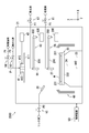
- FIG. 8 is a schematic plan view showing the hydrophilic treatment device 1A of the treatment device 200A according to the modified example.
- the processing device 200A includes a hydrophilic treatment device 1A in addition to the configuration of the processing device 200 shown in FIG.
- the substrate processing device 100 shown in FIG. 1 does not include the hydrophilic processing device 1 shown in FIG.
- the hydrophilic treatment apparatus 1A executes a predetermined treatment with a non-liquid on a plurality of structures 63 of the substrate W before supplying the treatment liquid LQ to the substrate W, and is more than before the execution of the predetermined treatment.
- the hydrophilicity of each surface 62 of the plurality of structures 63 is increased. Therefore, in the modified example, as in the first embodiment, the treatment liquid LQ can be promoted to infiltrate into the space SP between the plurality of structures 63, and the treatment liquid LQ can be effectively permeated into the space SP. As a result, the plurality of structures 63 can be effectively processed.
- the hydrophilic treatment device 1A includes an ultraviolet irradiation unit 3A and a moving unit 9.
- the ultraviolet irradiation unit 3A emits ultraviolet rays.
- the ultraviolet irradiation unit 3A includes, for example, a lamp that emits ultraviolet rays or a light emitting diode that emits ultraviolet rays.
- the ultraviolet irradiation unit 3A extends in a certain direction.
- the length of the ultraviolet irradiation unit 3A in the longitudinal direction is, for example, substantially the same as the diameter of the substrate W or substantially the same as the radius of the substrate W.
- the ultraviolet irradiation unit 3A irradiates the surfaces 62 of the plurality of structures 63 of the rotating substrate W with ultraviolet rays before supplying the treatment liquid LQ to the substrate W, and is more than before the irradiation with the ultraviolet rays. , Increase the hydrophilicity of each surface 62 of the plurality of structures 63.
- the surface 62 of the structure 63 can be effectively hydrophilized by irradiating with ultraviolet rays having an energy larger than that of visible light.
- the moving unit 9 moves the ultraviolet irradiation unit 3A between the processing position and the retracted position.
- the processing position indicates a position above the substrate W.
- the ultraviolet irradiation unit 3A irradiates the surfaces 62 of the plurality of structures 63 of the substrate W with ultraviolet rays.
- the retracted position indicates a position on the radial side of the substrate W with respect to the substrate W.
- the moving portion 9 includes an arm 92, a rotating shaft 94, and a moving mechanism 96.
- An ultraviolet irradiation unit 3A is attached to the arm 92.
- the arm 92 is driven by a rotation shaft 94 and a moving mechanism 96, is rotated along a substantially horizontal plane, or is moved up and down along a substantially vertical direction.
- the configurations of the arm 92, the rotating shaft 94, and the moving mechanism 96 are the same as the configurations of the arm 291, the rotating shaft 293, and the nozzle moving mechanism 295 shown in FIG. 4, respectively.
- the substrate processing method and the semiconductor manufacturing method according to the modified example will be described with reference to FIGS. 6 to 8.
- the substrate processing method and the semiconductor manufacturing method according to the modified example are the same as the substrate processing method and the semiconductor manufacturing method according to the first embodiment shown in FIGS. 6 and 7. However, the following points are different between the modified example and the first embodiment.
- the transfer robot CR carries the substrate W into the processing device 200A. Then, the rotation of the substrate W is started.
- step S22 the ultraviolet irradiation unit 3A shown in FIG. 8 irradiates the plurality of structures 63 of the rotating substrate W with ultraviolet rays for a predetermined time, and a plurality of ultraviolet irradiation units 3A are irradiated with ultraviolet rays as compared with before the irradiation of the ultraviolet rays. Increase the hydrophilicity of each surface 62 of the structure 63. Then, the rotation of the substrate W is stopped.
- step S23 is not executed. Therefore, when the step S22 is completed, the process returns to the main routine shown in FIG. In this case, in the modified example, the process S2 is not executed and the process proceeds to the process S4.
- the steps S3 to S8 are executed by the processing device 200A. Therefore, it is not required to carry the substrate W out of the processing device 200A in order to make the substrate W hydrophilic. As a result, the throughput when executing the substrate processing method and the semiconductor manufacturing method can be improved.
- the substrate processing method and the semiconductor manufacturing method according to the modified example do not have to include steps S5 to S7.
- the substrate processing apparatus 100 according to the second embodiment of the present invention will be described with reference to FIGS. 9 and 10.
- the second embodiment is mainly different from the first embodiment in that the processing apparatus 200B according to the second embodiment irradiates the substrate W with plasma to make the substrate W hydrophilic.
- the difference between the second embodiment and the first embodiment will be mainly described.
- FIG. 9 is a schematic cross-sectional view showing the processing device 200B according to the second embodiment.
- the processing device 200B includes a hydrophilic processing nozzle 45, a nozzle moving portion 47, a pipe P5, and a valve V5, in addition to the configuration of the processing device 200 shown in FIG.
- the substrate processing device 100 shown in FIG. 1 does not include the hydrophilic processing device 1 shown in FIG.
- the pipe P5 supplies gas to the hydrophilic treatment nozzle 45.
- the valve V5 switches between starting and stopping the supply of gas to the hydrophilic treatment nozzle 45.
- the gas is, for example, air, an inert gas, or oxygen.
- the inert gas is, for example, nitrogen, argon, or helium.
- the type of gas is not particularly limited as long as plasma can be generated.
- the hydrophilic treatment nozzle 45 executes a predetermined treatment with a non-liquid on a plurality of structures 63 of the substrate W before supplying the treatment liquid LQ to the substrate W, and is more than before the execution of the predetermined treatment.
- the hydrophilicity of each surface 62 of the plurality of structures 63 is increased. Therefore, in the second embodiment, as in the first embodiment, the treatment liquid LQ can be promoted to infiltrate into the space SP between the plurality of structures 63, and the treatment liquid LQ can be effectively permeated into the space SP. .. As a result, the plurality of structures 63 can be effectively treated by the treatment liquid LQ.
- the second embodiment has the same effect as that of the first embodiment.
- the hydrophilic treatment nozzle 45 corresponds to an example of the “hydrophilic treatment unit”.
- the predetermined process is a process of irradiating a plurality of structures 63 with plasma.
- the substrate W is dried before the execution of the predetermined treatment.
- the hydrophilic treatment nozzle 45 emits plasma. That is, the hydrophilic treatment nozzle 45 ionizes the gas supplied from the pipe P5 to generate plasma, and emits the plasma together with the gas. In other words, the hydrophilic treatment nozzle 45 puts the plasma on the air flow and emits it. In other words, the hydrophilic treatment nozzle 45 generates and emits a plasma flow.
- the hydrophilic treatment nozzle 45 irradiates the surfaces 62 of the plurality of structures 63 of the rotating substrate W with plasma before supplying the treatment liquid LQ to the substrate W.
- the hydrophilicity of each surface 62 of the plurality of structures 63 is increased as compared with that before the irradiation with plasma. It is considered that the reason why the hydrophilicity is increased is that the oxidation of the surface 62 of the structure 63 is promoted by the irradiation of plasma.
- the surface 62 of the structure 63 can be effectively hydrophilized by irradiating with plasma.
- the nozzle moving unit 47 moves the hydrophilic treatment nozzle 45 between the processing position and the retracting position.
- the processing position indicates a position above the substrate W.
- the hydrophilic treatment nozzle 45 is located at the treatment position, the surface 62 of the plurality of structures 63 of the substrate W is irradiated with plasma.
- the retracted position indicates a position on the radial side of the substrate W with respect to the substrate W.
- the nozzle moving portion 47 includes an arm 471, a rotating shaft 473, and a moving mechanism 475.
- a hydrophilic treatment nozzle 45 is attached to the tip of the arm 471.
- the arm 471 is driven by a rotating shaft 473 and a moving mechanism 475 to be rotated along a substantially horizontal plane or moved up and down along a substantially vertical direction.
- the configurations of the arm 471, the rotating shaft 473, and the moving mechanism 475 are the same as the configurations of the arm 291, the rotating shaft 293, and the nozzle moving mechanism 295 shown in FIG. 4, respectively.
- FIG. 10 is a cross-sectional view showing the hydrophilic treatment nozzle 45.
- the hydrophilic treatment nozzle 45 includes a first electrode 451 and a second electrode 453.
- the first electrode 451 is substantially columnar.
- the first electrode 451 is arranged in the flow path FW in the hydrophilic treatment nozzle 45.
- Gas is supplied to the flow path FW from the pipe P5.
- the second electrode 453 has a substantially cylindrical shape.
- the second electrode 453 is installed on the outer peripheral surface of the hydrophilic treatment nozzle 45.
- the processing device 200B further includes an AC power supply 46.
- the AC power supply 46 applies an AC voltage between the first electrode 451 and the second electrode 453.
- the plasma PM is emitted from the hydrophilic treatment nozzle 45 together with the gas.
- the plasma PM is, for example, atmospheric pressure plasma. Atmospheric pressure plasma is plasma generated in atmospheric pressure.
- the first electrode 451 and the second electrode 453 and the AC power supply 46 form a plasma generator 48.
- the configuration of the plasma generator 48 is not particularly limited as long as plasma can be generated. Further, the arrangement of the plasma generator 48 is not particularly limited as long as the substrate W can be irradiated with plasma.
- Each of the first electrode 451 and the second electrode 453 is formed of, for example, a carbon-containing resin.
- the carbon is, for example, a carbon nanotube.
- the resin is, for example, a fluororesin.
- the fluororesin is, for example, polytetrafluoroethylene (tetrafluoride) or polychlorotrifluoroethylene (trifluoride).
- the substrate processing method and the semiconductor manufacturing method according to the second embodiment will be described with reference to FIGS. 6, 7, and 9.
- the substrate processing method and the semiconductor manufacturing method according to the second embodiment are the same as the substrate processing method and the semiconductor manufacturing method according to the first embodiment shown in FIGS. 6 and 7.
- the second embodiment and the first embodiment differ in the following points.
- the transfer robot CR carries the substrate W into the processing device 200A. Then, the rotation of the substrate W is started.
- step S22 the hydrophilic treatment nozzle 45 shown in FIG. 9 irradiates the plurality of structures 63 of the substrate W with plasma for a predetermined time, and the plurality of structures 63 are more than before the plasma irradiation. Increase the hydrophilicity of each surface 62. Then, the rotation of the substrate W is stopped.
- the hydrophilic treatment nozzle 45 has a hydrophilicity corresponding to the contact angle CA when the permeation time of the treatment liquid LQ is substantially constant, so that the plurality of structures 63 have hydrophilicity with respect to the plurality of structures 63 of the substrate W. It is preferable to irradiate the plasma (FIG. 5). That is, it is preferable that the hydrophilic treatment nozzle 45 irradiates the plurality of structures 63 of the substrate W with plasma so that the contact angle CA is ⁇ 2 degrees or less (FIG. 5).
- step S23 is not executed. Therefore, when the step S22 is completed, the process returns to the main routine shown in FIG. In this case, in the second embodiment, the process S2 is not executed and the process proceeds to the process S4.
- the steps S3 to S8 are executed by the processing device 200B. Therefore, it is not required to carry the substrate W out of the processing device 200B in order to make the substrate W hydrophilic. As a result, the throughput when executing the substrate processing method and the semiconductor manufacturing method can be improved.
- the substrate processing method and the semiconductor manufacturing method according to the second embodiment may not include steps S5 to S7.
- the substrate processing apparatus 100 according to the third embodiment of the present invention will be described with reference to FIG.
- the third embodiment is mainly different from the second embodiment in that the processing apparatus 200C according to the third embodiment irradiates the substrate W with oxygen or an allotropes of oxygen to make the substrate W hydrophilic.
- the points that the third embodiment is different from the second embodiment will be mainly described.
- FIG. 11 is a schematic cross-sectional view showing the processing apparatus 200C according to the third embodiment.
- the processing device 200C replaces the hydrophilic processing nozzle 45, the nozzle moving portion 47, the pipe P5, and the valve V5 of the processing device 200B shown in FIG. 9, with the hydrophilic treatment nozzle 85, the pipe P6, and the like. Includes valve V6.
- the fluid supply unit 41A includes a hydrophilic treatment nozzle 85.
- the hydrophilic treatment nozzle 85 is arranged inside the blocking plate 411 and the support shaft 413. The tip of the hydrophilic treatment nozzle 85 is exposed from the lower surface of the blocking plate 411.
- the pipe P6 is connected to the hydrophilic treatment nozzle 85.
- the valve V6 switches between starting and stopping the supply of oxygen to the hydrophilic treatment nozzle 85.
- oxygen (O 2 ) or an allotrope of oxygen is supplied to the hydrophilic treatment nozzle 85.
- the gas supplied from the pipe P6 to the hydrophilic treatment nozzle 85 is not limited to oxygen, and may be an allotrope of oxygen.
- the allotropes of oxygen are, for example, ozone (O 3 ).
- the allotropes of oxygen are not particularly limited as long as the surface 62 of the structure 63 of the substrate W can be oxidized.
- the hydrophilic treatment nozzle 85 executes a predetermined treatment with a non-liquid on a plurality of structures 63 of the substrate W before supplying the treatment liquid LQ to the substrate W, and is more than before the execution of the predetermined treatment.
- the hydrophilicity of each surface 62 of the plurality of structures 63 is increased. Therefore, in the third embodiment, as in the second embodiment, the treatment liquid LQ can be promoted to infiltrate into the space SP between the plurality of structures 63, and the treatment liquid LQ can be effectively permeated into the space SP. .. As a result, the plurality of structures 63 can be effectively treated by the treatment liquid LQ.
- the third embodiment has the same effect as that of the second embodiment.
- the hydrophilic treatment nozzle 85 corresponds to an example of the “hydrophilic treatment unit”.
- the predetermined treatment is a treatment of supplying oxygen or an allotropes of oxygen to a plurality of structures 63.
- the substrate W is dried before the execution of the predetermined treatment.
- the hydrophilic treatment nozzle 85 supplies oxygen or an allotropes of oxygen to the surfaces 62 of the plurality of structures 63 of the rotating substrate W before supplying the treatment liquid LQ to the substrate W.
- the hydrophilicity of each surface 62 of the plurality of structures 63 is increased as compared with that before the supply of oxygen or allotropes of oxygen. It is considered that the reason why the hydrophilicity is increased is that the supply of oxygen or allotropes of oxygen exposes the surface 62 of the structure 63 to the allotropes of oxygen or oxygen, and the oxidation of the surface 62 of the structure 63 is promoted. ..
- the surface 62 of the structure 63 can be effectively hydrolyzed by supplying oxygen or an allotrope of oxygen.
- the hydrophilic treatment nozzle 85 When the valve V6 is opened when the fluid supply unit 41A is lowered and the hydrophilic treatment nozzle 85 is located in a close position, the hydrophilic treatment nozzle 85 is oxygenated or directed toward a plurality of structures 63 of the rotating substrate W. Supply allotropes of oxygen. Since the upper part of the substrate W is covered with the blocking plate 411, the plurality of structures 63 can be sufficiently exposed to oxygen or allotropes of oxygen. As a result, the surfaces 62 of the plurality of structures 63 can be effectively hydrophilized.
- the substrate processing method and the semiconductor manufacturing method according to the third embodiment will be described with reference to FIGS. 6, 7, and 11.
- the substrate processing method and the semiconductor manufacturing method according to the third embodiment are the same as the substrate processing method and the semiconductor manufacturing method according to the second embodiment described with reference to FIGS. 6 and 7.
- the following points are different between the third embodiment and the second embodiment.
- step S22 of FIG. 7 the hydrophilic treatment nozzle 85 shown in FIG. 11 supplies oxygen or allotropes of oxygen to the plurality of structures 63 of the substrate W over a predetermined period, and supplies oxygen or allotropes of oxygen.
- the hydrophilicity of each surface 62 of the plurality of structures 63 is made larger than before.
- the hydrophilic treatment nozzle 85 has a hydrophilicity corresponding to the contact angle CA when the permeation time of the treatment liquid LQ is substantially constant, so that the plurality of structures 63 have hydrophilicity with respect to the plurality of structures 63 of the substrate W. It is preferable to supply oxygen or an allotropes of oxygen (Fig. 5). That is, it is preferable that the hydrophilic treatment nozzle 85 supplies oxygen or an allotropes of oxygen to the plurality of structures 63 of the substrate W so that the contact angle CA is ⁇ 2 degrees or less (FIG. 5).
- the substrate processing apparatus 100 according to the fourth embodiment of the present invention will be described with reference to FIGS. 12 and 13.
- the fourth embodiment is mainly different from the first embodiment in that the processing apparatus 200D removes oxides from the substrate W.
- the points that the fourth embodiment is different from the first embodiment will be mainly described.
- FIG. 12 is a schematic cross-sectional view showing the processing device 200D according to the fourth embodiment.
- the processing device 200D includes a nozzle 81, a nozzle moving portion 83, a pipe P7, and a valve V7 in addition to the configuration of the processing device 200 shown in FIG.
- the substrate processing device 100 shown in FIG. 1 does not include the hydrophilic processing device 1 shown in FIG.
- the pipe P7 supplies the removal liquid to the nozzle 81.
- the valve V7 switches between starting and stopping the supply of the removing liquid to the nozzle 81.
- the removal liquid removes oxides from the substrate W.
- the removing liquid removes oxides formed on the surfaces 62 of the plurality of structures 63 of the substrate W.
- the removing liquid removes, for example, the silicon oxide film from the substrate W.
- the silicon oxide film is, for example, a natural oxide film.
- the removing solution is, for example, a chemical solution.
- the drug solution is, for example, hydrofluoric acid (HF), dilute hydrofluoric acid (DHF), or buffered hydrofluoric acid (BHF).
- the type of the removing liquid is not particularly limited as long as the oxide can be removed from the substrate W.
- the removal liquid is different from the treatment liquid LQ.
- the treatment liquid LQ is, for example, an etching liquid.
- the etching solution is, for example, an organic alkali (for example, TMAH: tetramethylammonium hydroxide) or a mixed solution of aqueous ammonia hydrogen peroxide (SC1).
- TMAH tetramethylammonium hydroxide
- SC1 aqueous ammonia hydrogen peroxide
- the type of etching solution is not particularly limited as long as the substrate W can be etched.
- the nozzle 81 supplies a removing liquid for removing oxides from the substrate W toward the substrate W before the hydrophilicity of each surface 62 of the plurality of structures 63 of the substrate W is increased.
- the nozzle 81 corresponds to an example of the “removal liquid supply unit”.
- the nozzle moving unit 83 moves the nozzle 81 between the processing position and the retracted position.
- the processing position indicates a position above the substrate W.
- the nozzle 81 supplies the removing liquid to the surfaces 62 of the plurality of structures 63 of the substrate W.
- the retracted position indicates a position on the radial side of the substrate W with respect to the substrate W.
- the nozzle moving unit 83 includes an arm 831, a rotating shaft 833, and a moving mechanism 835.
- a nozzle 81 is attached to the tip of the arm 831.
- the arm 831 is driven by a rotating shaft 833 and a moving mechanism 835 to be rotated along a substantially horizontal plane or moved up and down along a substantially vertical direction.
- the configurations of the arm 831, the rotating shaft 833, and the moving mechanism 835 are the same as the configurations of the arm 291 and the rotating shaft 293 and the nozzle moving mechanism 295 shown in FIG. 4, respectively.
- FIG. 13 is a flowchart showing a substrate processing method. As shown in FIG. 13, the substrate processing method includes steps S31 to S44. Steps S31 to S44 are executed according to the control by the control device U3.
- step S31 the transfer robot CR carries the substrate W into the processing device 200D. Then, the rotation of the substrate W is started.
- step S32 the nozzle 81 supplies the removing liquid toward the substrate W.
- a removing liquid for removing oxides formed on the surfaces 62 of the plurality of structures 63 is applied to the substrate W. Supply towards. As a result, the oxide is removed from the substrate W.
- step S33 the nozzle 30 supplies the rinse liquid to the substrate W.
- the removing liquid on the substrate W is washed away by the rinsing liquid, and the substrate W is washed.
- step S34 the spin motor 25 drives the spin chuck 23 to accelerate the spin chuck 23 to a high rotation speed, and the rotation speed of the spin chuck 23 is maintained at a high rotation speed.
- the substrate W rotates at a high rotation speed
- the rinse liquid adhering to the substrate W is shaken off, and the substrate W is washed.
- the spin motor 25 is stopped to stop the rotation of the spin chuck 23.
- the high rotation speed is higher than the rotation speed of the spin chuck 23 in the steps S32 and S33.
- step S35 the transfer robot CR carries out the substrate W from the processing device 200D.
- Steps S36 to S44 are executed. Steps S36 to S44 are the same as steps S1 to S9 in FIG. 6, respectively, and description thereof will be omitted.
- the plurality of structures 63 of the substrate W are hydrophilized before the treatment with the processing liquid LQ. Therefore, it is possible to promote the infiltration of the treatment liquid LQ into the space SP between the plurality of structures 63. As a result, the treatment liquid LQ quickly permeates the space SP between the plurality of structures 63, and the plurality of structures 63 can be effectively treated by the treatment liquid LQ.
- the fourth embodiment has the same effect as that of the first embodiment.
- a liquid for example, a removing liquid or a rinsing liquid
- the rinse liquid may be attached to a part of the substrate W, and the other part of the substrate W may be dried.
- the rinse liquid in the region near the center of the substrate W, the rinse liquid remains in the space SP between the structures 63, while the outer edge of the substrate W. In the region close to, the rinse solution may be completely removed from the space SP.
- the rinse liquid remaining in the space SP is replaced with the treatment liquid LQ, and the treatment liquid LQ permeates the space SP, but in the region near the outer edge of the substrate W, the treatment liquid It may be difficult for LQ to penetrate the space SP. Therefore, in the fourth embodiment, by making the surfaces 62 of the plurality of structures 63 of the substrate W hydrophilic in step S36, the space SP between the plurality of structures 63 is treated substantially uniformly over the entire substrate W.
- the liquid LQ can be rapidly permeated. As a result, it is possible to suppress the occurrence of variation in the treatment results of the plurality of structures 63 by the treatment liquid LQ.
- the treatment liquid LQ is an etching liquid, it is possible to suppress the occurrence of variations in the etching results of the plurality of structures 63.
- the semiconductor substrate W having the pattern PT including the plurality of structures 63 is processed by the substrate processing method including the steps S31 to S44, and the processed semiconductor substrate W is used.
- the substrate processing method and the semiconductor manufacturing method do not have to include steps S40 to S42.
- the present invention has been described above with reference to the drawings. However, the present invention is not limited to the above-described embodiment, and can be implemented in various embodiments without departing from the gist thereof.
- the plurality of components disclosed in the above embodiment can be appropriately modified. For example, one component of all components shown in one embodiment may be added to another component of another embodiment, or some component of all components shown in one embodiment. The element may be removed from the embodiment.
- the processing device 200D may include the hydrophilic treatment device 1A according to the modification of the first embodiment described with reference to FIG. ..
- the processing apparatus 200D according to the fourth embodiment may include the hydrophilic treatment nozzle 45, the nozzle moving portion 47, the pipe P5, and the valve V5 according to the second embodiment described with reference to FIG.
- the processing apparatus 200D according to the fourth embodiment may include the hydrophilic treatment nozzle 85, the pipe P6, and the valve V6 according to the third embodiment described with reference to FIG.
- the present invention relates to a substrate processing method, a semiconductor manufacturing method, and a substrate processing apparatus, and has industrial applicability.
Landscapes
- Cleaning Or Drying Semiconductors (AREA)
- Health & Medical Sciences (AREA)
- Toxicology (AREA)
- Weting (AREA)
Abstract
Description
図1~図7を参照して、本発明の実施形態1に係る基板処理装置100を説明する。基板処理装置100は処理液によって基板Wを処理する。以下、処理液を「処理液LQ」と記載する。基板Wは、例えば、半導体ウエハ、液晶表示装置用基板、プラズマディスプレイ用基板、電界放出ディスプレイ(Field Emission Display:FED)用基板、光ディスク用基板、磁気ディスク用基板、光磁気ディスク用基板、フォトマスク用基板、セラミック基板、又は、太陽電池用基板である。基板Wは、例えば、略円板状である。以下の実施形態1の説明では、基板Wは半導体基板である。
図8を参照して、本発明の実施形態1の変形例に係る基板処理装置100を説明する。変形例では、親水処理装置1Aが処理装置200Aに搭載されている点で、変形例は図1~図7を参照して説明した実施形態1と主に異なる。以下、変形例が実施形態1と異なる点を主に説明する。
図9および図10を参照して、本発明の実施形態2に係る基板処理装置100を説明する。実施形態2に係る処理装置200Bが基板Wにプラズマを照射して基板Wを親水化する点で、実施形態2は実施形態1と主に異なる。以下、実施形態2が実施形態1と異なる点を主に説明する。
図11を参照して、本発明の実施形態3に係る基板処理装置100を説明する。実施形態3に係る処理装置200Cが基板Wに酸素または酸素の同素体を照射して基板Wを親水化する点で、実施形態3は実施形態2と主に異なる。以下、実施形態3が実施形態2と異なる点を主に説明する。
図12および図13を参照して、本発明の実施形態4に係る基板処理装置100を説明する。実施形態4では、処理装置200Dが基板Wから酸化物を除去する点で、実施形態4は実施形態1と主に異なる。以下、実施形態4が実施形態1と異なる点を主に説明する。
23 スピンチャック(乾燥処理部)
27 ノズル(処理液供給部)
45、85 親水処理ノズル(親水処理部)
81 ノズル(除去液供給部)
415 ノズル(疎水処理部)
100 基板処理装置
W 基板
Claims (21)
- 複数の構造物を含むパターンを有する基板を処理する基板処理方法であって、
前記複数の構造物に対して非液体による所定処理を実行して、前記所定処理の実行前よりも、前記複数の構造物の各々の表面の親水性を大きくする工程と、
親水性を大きくする前記工程よりも後に、前記複数の構造物に向けて処理液を供給する工程と
を含む、基板処理方法。 - 親水性を大きくする前記工程よりも前に、前記基板から酸化物を除去する除去液を、前記複数の構造物に向けて供給する工程をさらに含む、請求項1に記載の基板処理方法。
- 前記所定処理は、前記複数の構造物に対して紫外線を照射する処理である、請求項1または請求項2に記載の基板処理方法。
- 前記所定処理は、前記複数の構造物に対してプラズマを照射する処理である、請求項1または請求項2に記載の基板処理方法。
- 前記所定処理は、前記複数の構造物に対して酸素または酸素の同素体を供給する処理である、請求項1に記載の基板処理方法。
- 前記処理液は、前記複数の構造物のうち互いに隣り合う構造物の間の空間に存在する気体を溶解する、請求項1から請求項5のいずれか1項に記載の基板処理方法。
- 前記処理液を供給する前記工程よりも後に、前記複数の構造物に向けて疎水化剤を供給して、前記疎水化剤の供給前よりも、前記複数の構造物の各々の表面の疎水性を大きくする工程と、
疎水性を大きくする前記工程よりも後に、前記基板を乾燥する工程と
をさらに含む、請求項1から請求項6のいずれか1項に記載の基板処理方法。 - 前記複数の構造物のうち互いに隣り合う構造物の間の距離は、所定条件を満たし、
前記所定条件は、親水性を大きくする前記工程よりも前では、前記処理液と同じ処理液が前記互いに隣り合う構造物の間の空間に浸透できないことを示す、請求項1から請求項7のいずれか1項に記載の基板処理方法。 - 前記所定条件は、第1条件および第2条件を含み、
前記第1条件は、親水性を大きくする前記工程よりも前では、毛細管現象によっては、前記処理液と同じ処理液が前記互いに隣り合う構造物の間の空間に浸透できないことを示し、
前記第2条件は、親水性を大きくする前記工程よりも後では、毛細管現象によって前記処理液が前記互いに隣り合う構造物の間の空間に浸透できることを示す、請求項8に記載の基板処理方法。 - 親水性を大きくする前記工程では、前記複数の構造物に対して前記所定処理を実行して、前記所定処理の実行前よりも、前記複数の構造物の各々が有する凹部の表面の親水性を大きくし、
前記凹部は、前記構造物の側壁面に対して、前記構造物が延びる方向に交差する方向に沿って凹んでいる、請求項1から請求項9のいずれか1項に記載の基板処理方法。 - 複数の構造物を含むパターンを有する半導体基板を処理して、処理後の前記半導体基板である半導体を製造する半導体製造方法であって、
前記複数の構造物に対して非液体による所定処理を実行して、前記所定処理の実行前よりも、前記複数の構造物の各々の表面の親水性を大きくする工程と、
親水性を大きくする前記工程よりも後に、前記複数の構造物に向けて処理液を供給する工程と
を含む、半導体製造方法。 - 複数の構造物を含むパターンを有する基板を処理する基板処理装置であって、
前記複数の構造物に対して非液体による所定処理を実行して、前記所定処理の実行前よりも、前記複数の構造物の各々の表面の親水性を大きくする親水処理部と、
前記複数の構造物の各々の表面の親水性が大きくされた時よりも後に、前記複数の構造物に向けて処理液を供給する処理液供給部と
を備える、基板処理装置。 - 前記複数の構造物の各々の表面の親水性が大きくされる前に、前記基板から酸化物を除去する除去液を、前記複数の構造物に向かって供給する除去液供給部をさらに備える、請求項12に記載の基板処理装置。
- 前記所定処理は、前記複数の構造物に対して紫外線を照射する処理である、請求項12または請求項13に記載の基板処理装置。
- 前記所定処理は、前記複数の構造物に対してプラズマを照射する処理である、請求項12または請求項13に記載の基板処理装置。
- 前記所定処理は、前記複数の構造物に対して酸素または酸素の同素体を供給する処理である、請求項12に記載の基板処理装置。
- 前記処理液は、前記複数の構造物のうち互いに隣り合う構造物の間の空間に存在する気体を溶解する、請求項12から請求項16のいずれか1項に記載の基板処理装置。
- 前記処理液が前記複数の構造物に向けて供給された時よりも後に、前記複数の構造物に向けて疎水化剤を供給して、前記疎水化剤の供給前よりも、前記複数の構造物の各々の表面の疎水性を大きくする疎水処理部と、
前記複数の構造物の各々の表面の疎水性が大きくされた時よりも後に、前記基板を乾燥する乾燥処理部と
をさらに備える、請求項12から請求項17のいずれか1項に記載の基板処理装置。 - 前記複数の構造物のうち互いに隣り合う構造物の間の距離は、所定条件を満たし、
前記所定条件は、前記複数の構造物の各々の表面の親水性が大きくされる前では、前記処理液と同じ処理液が前記互いに隣り合う構造物の間の空間に浸透できないことを示す、請求項12から請求項18のいずれか1項に記載の基板処理装置。 - 前記所定条件は、第1条件および第2条件を含み、
前記第1条件は、前記複数の構造物の各々の表面の親水性が大きくされる前では、毛細管現象によっては、前記処理液と同じ処理液が前記互いに隣り合う構造物の間の空間に浸透できないことを示し、
前記第2条件は、前記複数の構造物の各々の表面の親水性が大きくされた後では、毛細管現象によって前記処理液が前記互いに隣り合う構造物の間の空間に浸透できることを示す、請求項19に記載の基板処理装置。 - 前記親水処理部は、前記複数の構造物に対して前記所定処理を実行して、前記所定処理の実行前よりも、前記複数の構造物の各々が有する凹部の表面の親水性を大きくし、
前記凹部は、前記構造物の側壁面に対して、前記構造物が延びる方向に交差する方向に沿って凹んでいる、請求項12から請求項20のいずれか1項に記載の基板処理装置。
Priority Applications (3)
| Application Number | Priority Date | Filing Date | Title |
|---|---|---|---|
| CN202080022944.2A CN113614887B (zh) | 2019-03-20 | 2020-01-24 | 基板处理方法、半导体制造方法及基板处理装置 |
| US17/440,212 US20220148888A1 (en) | 2019-03-20 | 2020-01-24 | Substrate processing method, semiconductor production method, and substrate processing apparatus |
| KR1020217032424A KR102638633B1 (ko) | 2019-03-20 | 2020-01-24 | 기판 처리 방법, 반도체 제조 방법, 및, 기판 처리 장치 |
Applications Claiming Priority (2)
| Application Number | Priority Date | Filing Date | Title |
|---|---|---|---|
| JP2019-053333 | 2019-03-20 | ||
| JP2019053333A JP7311988B2 (ja) | 2019-03-20 | 2019-03-20 | 基板処理方法、半導体製造方法、および、基板処理装置 |
Publications (1)
| Publication Number | Publication Date |
|---|---|
| WO2020189010A1 true WO2020189010A1 (ja) | 2020-09-24 |
Family
ID=72519296
Family Applications (1)
| Application Number | Title | Priority Date | Filing Date |
|---|---|---|---|
| PCT/JP2020/002540 Ceased WO2020189010A1 (ja) | 2019-03-20 | 2020-01-24 | 基板処理方法、半導体製造方法、および、基板処理装置 |
Country Status (6)
| Country | Link |
|---|---|
| US (1) | US20220148888A1 (ja) |
| JP (1) | JP7311988B2 (ja) |
| KR (1) | KR102638633B1 (ja) |
| CN (1) | CN113614887B (ja) |
| TW (1) | TWI732450B (ja) |
| WO (1) | WO2020189010A1 (ja) |
Families Citing this family (3)
| Publication number | Priority date | Publication date | Assignee | Title |
|---|---|---|---|---|
| JP7768669B2 (ja) * | 2020-09-30 | 2025-11-12 | 芝浦メカトロニクス株式会社 | 基板処理装置、および基板処理方法 |
| JP7653814B2 (ja) | 2021-03-18 | 2025-03-31 | 株式会社Screenホールディングス | 基板処理方法、および、基板処理装置 |
| JP2023076165A (ja) | 2021-11-22 | 2023-06-01 | 株式会社Screenホールディングス | 基板処理方法 |
Citations (5)
| Publication number | Priority date | Publication date | Assignee | Title |
|---|---|---|---|---|
| JPH0380538A (ja) * | 1989-05-06 | 1991-04-05 | Dainippon Screen Mfg Co Ltd | 基板の表面処理方法 |
| JPH0497526A (ja) * | 1990-08-15 | 1992-03-30 | Dainippon Screen Mfg Co Ltd | 基板の表面処理方法 |
| JP2009272411A (ja) * | 2008-05-02 | 2009-11-19 | Sumco Techxiv株式会社 | 半導体ウェーハの処理方法及び処理装置 |
| JP2010251596A (ja) * | 2009-04-17 | 2010-11-04 | Toshiba Corp | 半導体装置の製造方法 |
| JP2011204944A (ja) * | 2010-03-26 | 2011-10-13 | Dainippon Screen Mfg Co Ltd | 基板処理装置および基板処理方法 |
Family Cites Families (15)
| Publication number | Priority date | Publication date | Assignee | Title |
|---|---|---|---|---|
| JP4118537B2 (ja) * | 2001-07-31 | 2008-07-16 | 東京エレクトロン株式会社 | 半導体ウエーハまたは液晶基板の処理装置用ゴムシール材及びその製造方法、半導体基板または液晶基板の処理装置 |
| JPWO2005096684A1 (ja) * | 2004-03-31 | 2008-02-21 | 大見 忠弘 | 回路基板、回路基板の製造方法及び回路基板を備えた表示装置 |
| JPWO2009113717A1 (ja) * | 2008-03-14 | 2011-07-21 | 昭和電工株式会社 | 燃料電池用セパレータおよびその製造方法 |
| TWI438562B (zh) * | 2009-01-06 | 2014-05-21 | Hoya股份有限公司 | 光罩之製造方法、圖案轉印方法、光罩基板用處理裝置及薄膜圖案化方法 |
| JP2011071169A (ja) * | 2009-09-24 | 2011-04-07 | Dainippon Screen Mfg Co Ltd | 基板処理方法および基板処理装置 |
| JP5404361B2 (ja) * | 2009-12-11 | 2014-01-29 | 株式会社東芝 | 半導体基板の表面処理装置及び方法 |
| JP2011233694A (ja) * | 2010-04-27 | 2011-11-17 | Elpida Memory Inc | 半導体装置の製造方法 |
| US8716146B2 (en) * | 2012-07-03 | 2014-05-06 | Intermolecular, Inc | Low temperature etching of silicon nitride structures using phosphoric acid solutions |
| JP6081728B2 (ja) * | 2012-07-30 | 2017-02-15 | 東京エレクトロン株式会社 | 基板処理方法、コンピュータ記憶媒体及び基板処理システム |
| JP5977727B2 (ja) * | 2013-11-13 | 2016-08-24 | 東京エレクトロン株式会社 | 基板洗浄方法、基板洗浄システムおよび記憶媒体 |
| JP6304592B2 (ja) * | 2014-03-25 | 2018-04-04 | 株式会社Screenホールディングス | 基板処理方法および基板処理装置 |
| US9853101B2 (en) * | 2015-10-07 | 2017-12-26 | Taiwan Semiconductor Manufacturing Company, Ltd. | Strained nanowire CMOS device and method of forming |
| CN108475695B (zh) * | 2016-01-05 | 2021-10-15 | 应用材料公司 | 制造用于半导体应用的环绕式水平栅极器件的纳米线的方法 |
| JP6825956B2 (ja) | 2017-03-28 | 2021-02-03 | 株式会社Screenホールディングス | 基板処理装置、基板処理方法および紫外線照射手段の選択方法 |
| US10510610B2 (en) * | 2018-03-28 | 2019-12-17 | Varian Semiconductor Equipment Associates, Inc. | Structure and method of forming fin device having improved fin liner |
-
2019
- 2019-03-20 JP JP2019053333A patent/JP7311988B2/ja active Active
-
2020
- 2020-01-24 US US17/440,212 patent/US20220148888A1/en active Pending
- 2020-01-24 CN CN202080022944.2A patent/CN113614887B/zh active Active
- 2020-01-24 KR KR1020217032424A patent/KR102638633B1/ko active Active
- 2020-01-24 WO PCT/JP2020/002540 patent/WO2020189010A1/ja not_active Ceased
- 2020-02-10 TW TW109104036A patent/TWI732450B/zh active
Patent Citations (5)
| Publication number | Priority date | Publication date | Assignee | Title |
|---|---|---|---|---|
| JPH0380538A (ja) * | 1989-05-06 | 1991-04-05 | Dainippon Screen Mfg Co Ltd | 基板の表面処理方法 |
| JPH0497526A (ja) * | 1990-08-15 | 1992-03-30 | Dainippon Screen Mfg Co Ltd | 基板の表面処理方法 |
| JP2009272411A (ja) * | 2008-05-02 | 2009-11-19 | Sumco Techxiv株式会社 | 半導体ウェーハの処理方法及び処理装置 |
| JP2010251596A (ja) * | 2009-04-17 | 2010-11-04 | Toshiba Corp | 半導体装置の製造方法 |
| JP2011204944A (ja) * | 2010-03-26 | 2011-10-13 | Dainippon Screen Mfg Co Ltd | 基板処理装置および基板処理方法 |
Also Published As
| Publication number | Publication date |
|---|---|
| TWI732450B (zh) | 2021-07-01 |
| KR102638633B1 (ko) | 2024-02-20 |
| CN113614887A (zh) | 2021-11-05 |
| JP2020155612A (ja) | 2020-09-24 |
| KR20210129219A (ko) | 2021-10-27 |
| CN113614887B (zh) | 2025-07-01 |
| JP7311988B2 (ja) | 2023-07-20 |
| TW202040670A (zh) | 2020-11-01 |
| US20220148888A1 (en) | 2022-05-12 |
Similar Documents
| Publication | Publication Date | Title |
|---|---|---|
| CN101131547B (zh) | 处理基材的设备和方法 | |
| CN1319131C (zh) | 处理一种如半导体晶片的工件的方法和设备 | |
| KR102314607B1 (ko) | 기판 세정 방법, 기판 세정 시스템 및 기억 매체 | |
| JP4986565B2 (ja) | 基板処理方法および基板処理装置 | |
| JP7233294B2 (ja) | 基板処理方法、半導体製造方法、および、基板処理装置 | |
| US20030192577A1 (en) | Method and apparatus for wafer cleaning | |
| JP6875811B2 (ja) | パターン倒壊回復方法、基板処理方法および基板処理装置 | |
| JP5424848B2 (ja) | 半導体基板の表面処理装置及び方法 | |
| KR102638633B1 (ko) | 기판 처리 방법, 반도체 제조 방법, 및, 기판 처리 장치 | |
| JP6948840B2 (ja) | 基板処理方法および基板処理装置 | |
| US10593587B2 (en) | Substrate treatment apparatus | |
| US9966266B2 (en) | Apparatus for semiconductor wafer treatment and semiconductor wafer treatment | |
| JP5680705B2 (ja) | 基板処理方法 | |
| JP5276559B2 (ja) | 基板処理方法および基板処理装置 | |
| KR20230135511A (ko) | 칩의 제조 방법 | |
| JP2020155603A (ja) | 基板処理方法および基板処理装置 | |
| JP7633058B2 (ja) | 基板処理方法及び基板処理装置 | |
| JP2024075336A (ja) | 基板処理装置および基板処理方法 | |
| KR100787736B1 (ko) | 반도체 제조용 드라이 에칭 장치 | |
| KR20250063807A (ko) | 기판세정장치 및 기판세정장치의 세정노즐 | |
| JP6268410B2 (ja) | 基板処理装置および基板処理方法 |
Legal Events
| Date | Code | Title | Description |
|---|---|---|---|
| 121 | Ep: the epo has been informed by wipo that ep was designated in this application |
Ref document number: 20772691 Country of ref document: EP Kind code of ref document: A1 |
|
| NENP | Non-entry into the national phase |
Ref country code: DE |
|
| ENP | Entry into the national phase |
Ref document number: 20217032424 Country of ref document: KR Kind code of ref document: A |
|
| 122 | Ep: pct application non-entry in european phase |
Ref document number: 20772691 Country of ref document: EP Kind code of ref document: A1 |
|
| WWG | Wipo information: grant in national office |
Ref document number: 202080022944.2 Country of ref document: CN |