WO2020184124A1 - 固相接合用耐候性鋼、固相接合用耐候性鋼材、固相接合構造物及び固相接合方法 - Google Patents
固相接合用耐候性鋼、固相接合用耐候性鋼材、固相接合構造物及び固相接合方法 Download PDFInfo
- Publication number
- WO2020184124A1 WO2020184124A1 PCT/JP2020/006684 JP2020006684W WO2020184124A1 WO 2020184124 A1 WO2020184124 A1 WO 2020184124A1 JP 2020006684 W JP2020006684 W JP 2020006684W WO 2020184124 A1 WO2020184124 A1 WO 2020184124A1
- Authority
- WO
- WIPO (PCT)
- Prior art keywords
- steel
- solid phase
- solid
- phase bonding
- mass
- Prior art date
- Legal status (The legal status is an assumption and is not a legal conclusion. Google has not performed a legal analysis and makes no representation as to the accuracy of the status listed.)
- Ceased
Links
Images










Classifications
-
- C—CHEMISTRY; METALLURGY
- C22—METALLURGY; FERROUS OR NON-FERROUS ALLOYS; TREATMENT OF ALLOYS OR NON-FERROUS METALS
- C22C—ALLOYS
- C22C38/00—Ferrous alloys, e.g. steel alloys
- C22C38/002—Ferrous alloys, e.g. steel alloys containing In, Mg, or other elements not provided for in one single group C22C38/001 - C22C38/60
-
- B—PERFORMING OPERATIONS; TRANSPORTING
- B23—MACHINE TOOLS; METAL-WORKING NOT OTHERWISE PROVIDED FOR
- B23K—SOLDERING OR UNSOLDERING; WELDING; CLADDING OR PLATING BY SOLDERING OR WELDING; CUTTING BY APPLYING HEAT LOCALLY, e.g. FLAME CUTTING; WORKING BY LASER BEAM
- B23K20/00—Non-electric welding by applying impact or other pressure, with or without the application of heat, e.g. cladding or plating
- B23K20/12—Non-electric welding by applying impact or other pressure, with or without the application of heat, e.g. cladding or plating the heat being generated by friction; Friction welding
-
- B—PERFORMING OPERATIONS; TRANSPORTING
- B23—MACHINE TOOLS; METAL-WORKING NOT OTHERWISE PROVIDED FOR
- B23K—SOLDERING OR UNSOLDERING; WELDING; CLADDING OR PLATING BY SOLDERING OR WELDING; CUTTING BY APPLYING HEAT LOCALLY, e.g. FLAME CUTTING; WORKING BY LASER BEAM
- B23K20/00—Non-electric welding by applying impact or other pressure, with or without the application of heat, e.g. cladding or plating
- B23K20/12—Non-electric welding by applying impact or other pressure, with or without the application of heat, e.g. cladding or plating the heat being generated by friction; Friction welding
- B23K20/1205—Non-electric welding by applying impact or other pressure, with or without the application of heat, e.g. cladding or plating the heat being generated by friction; Friction welding using translation movement
-
- B—PERFORMING OPERATIONS; TRANSPORTING
- B23—MACHINE TOOLS; METAL-WORKING NOT OTHERWISE PROVIDED FOR
- B23K—SOLDERING OR UNSOLDERING; WELDING; CLADDING OR PLATING BY SOLDERING OR WELDING; CUTTING BY APPLYING HEAT LOCALLY, e.g. FLAME CUTTING; WORKING BY LASER BEAM
- B23K20/00—Non-electric welding by applying impact or other pressure, with or without the application of heat, e.g. cladding or plating
- B23K20/12—Non-electric welding by applying impact or other pressure, with or without the application of heat, e.g. cladding or plating the heat being generated by friction; Friction welding
- B23K20/122—Non-electric welding by applying impact or other pressure, with or without the application of heat, e.g. cladding or plating the heat being generated by friction; Friction welding using a non-consumable tool, e.g. friction stir welding
-
- B—PERFORMING OPERATIONS; TRANSPORTING
- B23—MACHINE TOOLS; METAL-WORKING NOT OTHERWISE PROVIDED FOR
- B23K—SOLDERING OR UNSOLDERING; WELDING; CLADDING OR PLATING BY SOLDERING OR WELDING; CUTTING BY APPLYING HEAT LOCALLY, e.g. FLAME CUTTING; WORKING BY LASER BEAM
- B23K20/00—Non-electric welding by applying impact or other pressure, with or without the application of heat, e.g. cladding or plating
- B23K20/12—Non-electric welding by applying impact or other pressure, with or without the application of heat, e.g. cladding or plating the heat being generated by friction; Friction welding
- B23K20/129—Non-electric welding by applying impact or other pressure, with or without the application of heat, e.g. cladding or plating the heat being generated by friction; Friction welding specially adapted for particular articles or work
-
- B—PERFORMING OPERATIONS; TRANSPORTING
- B23—MACHINE TOOLS; METAL-WORKING NOT OTHERWISE PROVIDED FOR
- B23K—SOLDERING OR UNSOLDERING; WELDING; CLADDING OR PLATING BY SOLDERING OR WELDING; CUTTING BY APPLYING HEAT LOCALLY, e.g. FLAME CUTTING; WORKING BY LASER BEAM
- B23K20/00—Non-electric welding by applying impact or other pressure, with or without the application of heat, e.g. cladding or plating
- B23K20/22—Non-electric welding by applying impact or other pressure, with or without the application of heat, e.g. cladding or plating taking account of the properties of the materials to be welded
- B23K20/227—Non-electric welding by applying impact or other pressure, with or without the application of heat, e.g. cladding or plating taking account of the properties of the materials to be welded with ferrous layer
-
- C—CHEMISTRY; METALLURGY
- C22—METALLURGY; FERROUS OR NON-FERROUS ALLOYS; TREATMENT OF ALLOYS OR NON-FERROUS METALS
- C22C—ALLOYS
- C22C38/00—Ferrous alloys, e.g. steel alloys
-
- C—CHEMISTRY; METALLURGY
- C22—METALLURGY; FERROUS OR NON-FERROUS ALLOYS; TREATMENT OF ALLOYS OR NON-FERROUS METALS
- C22C—ALLOYS
- C22C38/00—Ferrous alloys, e.g. steel alloys
- C22C38/02—Ferrous alloys, e.g. steel alloys containing silicon
-
- C—CHEMISTRY; METALLURGY
- C22—METALLURGY; FERROUS OR NON-FERROUS ALLOYS; TREATMENT OF ALLOYS OR NON-FERROUS METALS
- C22C—ALLOYS
- C22C38/00—Ferrous alloys, e.g. steel alloys
- C22C38/04—Ferrous alloys, e.g. steel alloys containing manganese
-
- C—CHEMISTRY; METALLURGY
- C22—METALLURGY; FERROUS OR NON-FERROUS ALLOYS; TREATMENT OF ALLOYS OR NON-FERROUS METALS
- C22C—ALLOYS
- C22C38/00—Ferrous alloys, e.g. steel alloys
- C22C38/18—Ferrous alloys, e.g. steel alloys containing chromium
- C22C38/20—Ferrous alloys, e.g. steel alloys containing chromium with copper
-
- C—CHEMISTRY; METALLURGY
- C22—METALLURGY; FERROUS OR NON-FERROUS ALLOYS; TREATMENT OF ALLOYS OR NON-FERROUS METALS
- C22C—ALLOYS
- C22C38/00—Ferrous alloys, e.g. steel alloys
- C22C38/18—Ferrous alloys, e.g. steel alloys containing chromium
- C22C38/40—Ferrous alloys, e.g. steel alloys containing chromium with nickel
- C22C38/58—Ferrous alloys, e.g. steel alloys containing chromium with nickel with more than 1.5% by weight of manganese
-
- B—PERFORMING OPERATIONS; TRANSPORTING
- B23—MACHINE TOOLS; METAL-WORKING NOT OTHERWISE PROVIDED FOR
- B23K—SOLDERING OR UNSOLDERING; WELDING; CLADDING OR PLATING BY SOLDERING OR WELDING; CUTTING BY APPLYING HEAT LOCALLY, e.g. FLAME CUTTING; WORKING BY LASER BEAM
- B23K2103/00—Materials to be soldered, welded or cut
- B23K2103/02—Iron or ferrous alloys
- B23K2103/04—Steel or steel alloys
Definitions
- a weathering steel for solid phase bonding a steel material for solid phase bonding, a solid phase bonding structure having the weathering steel for solid phase bonding, and a weathering resistance for solid phase bonding can be preferably used.
- the present invention relates to a solid-state bonding method for steel.
- solid-phase bonding methods that can reduce the decrease in strength of joints compared to conventional hot-dip welding, and in particular, solid-phase bonding methods that utilize frictional heat generation and plastic deformation of metal materials are being actively studied.
- the solid-state joining method include “friction stir welding (FSW)” in which a columnar tool rotating at high speed is press-fitted into a material to be joined, and a rotating columnar material to be fixed is fixed.
- FSW frequency stir welding
- Examples thereof include “friction pressure welding” in which the materials to be joined are brought into contact with each other and joined, and “linear friction welding” in which the materials to be joined are reciprocated to be joined in a state of being in contact with each other.
- Patent Document 1 (Special According to Kai 2008-31494), the total of the temperature range width of a low alloy structural steel, which is a single ferrite phase in an equilibrium state of 600 ° C. or higher, and the temperature range width of two phases, an austenite phase and a ferrite phase, is A low alloy structural steel for frictional agitation welding, which is characterized by having a temperature of 200 ° C. or higher, is disclosed.
- the deformation resistance of the steel in friction stir welding is increased by expanding the ferrite single phase region and the austenite phase-ferrite two phase region in the vicinity of the ultimate temperature of the joint.
- the durability of the rotating tool is improved, and restrictions on joining conditions such as joining speed are relaxed.
- the frequency of replacement work due to wear and tear of the tool is suppressed, and the joining time is shortened, so that the construction efficiency is improved.
- Patent Document 2 Japanese Unexamined Patent Publication No. 2014-162971
- the mass is%. C: 0.40 to 1.50%
- balance Fe and inevitable A steel for friction stir welding process, which is composed of impurities, is disclosed.
- Patent Document 3 Japanese Unexamined Patent Publication No. 2018-16866
- the steel composition is C: 0.20 to 0.45% and Cr: 1.00 to 3.50 in mass%.
- a friction stir welding steel which contains% and has a carbon equivalent CE defined by the formula A of 0.40 to 1.00% by mass.
- CE C + Mn / 6 + (Cu + Ni) / 15+ (Cr + Mo + V) / 5 ...
- the element symbol described in the formula (A) indicates the content of each component in the friction stir welding steel material in unit mass%.
- the friction stir welding steel described in Patent Document 3 is a steel capable of obtaining joint characteristics (tensile strength and breaking toughness of the stirring portion, etc.) equal to or higher than those of conventional high-strength steel by friction stir welding. It is said that it is possible to provide a steel to which only a relatively inexpensive alloy element is added to a minimum, and a friction stir welding method using the steel as a material to be joined.
- the low alloy structural steel disclosed in Patent Document 1 facilitates the application of friction stir welding to steel by reducing the deformation resistance of the steel during the process, and the joint portion (stirring portion). ), The cost and availability of elements added to steel are hardly considered. Further, in recent years, the demand for long-term reliability of steel structures has been increasing, and the low alloy structural steels disclosed in Patent Document 1 have not been considered for weather resistance at all.
- the friction stir process steel disclosed in Patent Document 2 has an optimized composition for surface quenching using frictional heat, and an object of ensuring the mechanical properties of the joint.
- the design guideline is completely different from that of the steel material.
- the weather resistance of the steel is not considered at all. It cannot be suitably used for structures such as bridges that require corrosion resistance.
- the additive elements are limited for the purpose of suppressing welding cracks. More specifically, it is known that the corrosion resistance is improved by adding Cu or P, but since these elements cause welding cracks, the amount of Cu added is generally 0.3 mass by mass. % And P are added in an amount of about 0.01% by mass.
- an object of the present invention is a weathering steel for solid phase bonding having a tensile property equivalent to that of high tension steel, in which a good joint portion is formed by solid phase bonding.
- weathering steel for solid-phase bonding and weathering steel for solid-phase bonding which have superior weathering resistance to conventional weathering steel for welding and have a joint reliability equal to or higher than that of the base material.
- Another object of the present invention is to provide a solid-phase bonding structure having the weathering steel for solid-phase bonding of the present invention and a method for solid-phase bonding of the weathering steel for solid-phase bonding.
- the present inventor has conducted extensive research on the relationship between the composition of steel and weather resistance, and the relationship between the composition of steel and the mechanical properties of the base metal and solid-phase joint, and as a result, based on carbon steel. We have found that increasing the amount of P added is extremely effective, and have reached the present invention.
- the steel composition is mass%, C: 0.10 to 0.60%, P: Containing more than 0.035 to 1.000%, The balance is composed only of Fe and unavoidable impurities, Provided is a weathering steel for solid phase bonding.
- the weathering steel for solid phase bonding of the present invention is premised on bonding by solid phase bonding, but the method of solid phase bonding is not particularly limited as long as the effect of the present invention is not impaired, and various conventionally known solids A phase joining method can be used.
- Typical solid phase welding methods include friction stir welding, friction welding and linear friction welding.
- the upper limit of the P content of the weathering steel sheet (GIS G3114) for welded structures that guarantees weldability is limited to 0.035%.
- the corrosion resistance (weather resistance) of steel is clearly improved by densification of protective rust, and the effect is increased up to about 1.0% by mass.
- the weathering steel for solid-phase bonding of the present invention is premised on the use of solid-phase bonding, and since it is not necessary to consider cracks due to melt welding, the P content is more than 0.035 to 1.00 mass. It is%.
- the content of P is preferably 0.050 to 0.500% by mass, and more preferably 0.080 to 0.300% by mass.
- the C content is 0.10 to 0.60% by mass in order to realize the tensile strength equivalent to that of the high-strength steel plate. If the C content is increased, cracks are likely to occur during welding, but by assuming the use of solid phase bonding, a relatively large amount of C can be contained.
- the content of C is preferably small, the upper limit is more preferably 0.50% by mass, and most preferably 0.30% by mass. For example, although it depends on other additive elements and structure, a tensile strength of 490 MPa or more can be obtained by setting the carbon content to 0.30% by mass.
- the weathering steel for solid phase bonding of the present invention further contains more than 0 to 3.00% by mass of Cu.
- the protective rust is densified and the weather resistance (corrosion resistance) is improved. This effect is exhibited when even a small amount of Cu is added, but even if it is added in an amount of 3.00% by mass or more, no significant improvement is expected.
- the upper limit is 3.00. It is mass%.
- the amount of Cu added is preferably 0.10 to 2.00% by mass, more preferably 0.30 to 1.00% by mass.
- the weathering steel for solid phase bonding of the present invention further contains Mn in an amount of more than 0 to 2.00% by mass. It is considered that the inclusion of Mn suppresses the formation of proeutectoid ferrite and increases the amount of solid solution strengthening.
- the more preferable content of Mn is 0.25 to 0.75% by mass.
- the weathering steel for solid phase bonding of the present invention further contains Si in an amount of more than 0 to 1.00% by mass.
- Si it is possible to prevent the solid phase joint from being softened by heat, and it is expected that the effect of suppressing the formation of cementite, which reduces ductility, can be expected.
- it is set to 1.00% or less the decrease in toughness can be suppressed.
- the weathering steel for solid phase bonding of the present invention further contains Cr in an amount of more than 0 to 2.00% by mass.
- Cr in an amount of more than 0 to 2.00% by mass.
- the weathering steel for solid phase bonding of the present invention further contains more than 0 to 3.00% by mass of Ni.
- the weather resistance of the weathering steel for solid phase bonding can be further improved.
- the weathering steel for solid phase bonding of the present invention further contains Mo in an amount of more than 0 to 1.00% by mass.
- Mo in an amount of more than 0 to 1.00% by mass, the weather resistance of the weathering steel for solid phase bonding can be further improved.
- the weathering steel for solid phase bonding of the present invention preferably further contains Ti in an amount of more than 0 to 0.03% by mass. By containing more than 0 to 0.03% by mass of Ti, the weather resistance of the weathering steel for solid phase bonding can be further improved.
- the present invention is a bonding structure having a solid phase bonding portion of the weathering steel for solid phase bonding of the present invention, and the impact absorption energy of the solid phase bonding portion is the weathering steel for solid phase bonding (solid). Also provided is a solid phase bonding structure characterized by having 90% or more of the impact absorption energy of the weathering steel base material for phase bonding).
- the material of the bonded structure other than the weathering steel for solid phase bonding, the shape and size of the structure, and the like are not particularly limited, and various conventionally known structures can be used.
- the weathering steel for solid phase bonding of the present invention is used for the solid phase bonding structure of the present invention, it is better than the structure in which the conventional weathering steel for welded structure is used. Has weather resistance. If necessary, the surface of the weathering steel for solid phase bonding may be coated to improve corrosion resistance, but it may be uncoated depending on the usage environment.
- the impact absorption energy of the solid phase bonding portion of the weathering steel for solid phase bonding is 90% or more of the impact absorption energy of the base material, and the solid phase bonding structure of the present invention has extremely high reliability.
- the shock absorption energy of the solid phase joint is preferably 95% or more, more preferably 100% or more of the shock absorption energy of the base metal.
- the method for measuring the shock absorption energy is not particularly limited as long as the effect of the present invention is not impaired, and various conventionally known measuring methods can be used. For example, a minute test piece is cut out from the joint and the subject is concerned. A micro-impact test may be performed on the test piece. In the stress-displacement curve obtained in the micro-impact test, the impact absorption energy can be calculated from the area of the region surrounded by the curve.
- the present invention also provides a weathering steel material for solid phase bonding, which comprises the weathering steel for solid phase bonding of the present invention and has a mixed structure of ferrite and fine cementite. Since the weathering steel for solid phase bonding of the present invention has a mixed structure composed of ferrite and fine cementite, it is possible to exhibit high strength and reliability in addition to excellent weather resistance.
- the mixing structure consisting of ferrite and fine cementite, for example, can be obtained by performing the friction stir process at the following three points A against solid bonding weathering steel of the present invention.
- the present invention is a method of solid-phase bonding to the weather-resistant steel for solid-phase bonding of the present invention, and the bonding temperature is set to A 3 points or less determined by the chemical composition of the weather-resistant steel for solid-phase bonding.
- a solid phase bonding method characterized in that.
- the solid-phase bonding weathering steel of the present invention comprise a large number of P, P from raising the three points A steel, readily A 3-point below compared to conventional steel Solid phase bonding can be performed.
- the toughness of the joint is increased. May decrease.
- the bonding temperature of the solid phase bonding is set to A 3 point or less, which is determined by the chemical composition of the weathering steel for solid phase bonding, the toughness of the solid phase bonding portion can be improved and the solid phase can be improved.
- the impact absorption energy of the joint can be made higher than the impact absorption energy of the base material.
- the bonding temperature of the solid phase bonding is set to A 3 or less, which is determined by the chemical composition of the weathering steel for solid phase bonding, the impact absorption energy of the solid phase bonding portion is less than 90% of the impact absorption energy of the base material.
- the bonding temperature is A 1 point or less, which is determined by the chemical composition of the weathering steel for solid phase bonding.
- the solid phase bonding method of the present invention it is preferable to use any one of friction stir welding, friction welding and linear solid phase welding.
- the bonding temperature it is necessary to control the bonding temperature, but by using these solid-phase bonding methods, the bonding temperature can be accurately determined.
- the joining temperature can be controlled by the shape, size and material of the tool, joining speed, joining load, tool rotation speed, and the like.
- the bonding temperature can be controlled by the bonding pressure applied to the interface to be bonded.
- the present invention is a weathering steel for solid phase bonding having a tensile property equivalent to that of high tension steel, in which a good joint portion is formed by solid phase bonding, and is more than a conventional weathering steel for welding. It is possible to provide a weathering steel for solid phase bonding and a weathering steel material for solid phase bonding, which have excellent weather resistance and the reliability of the joint portion is equal to or higher than that of the base material. Further, according to the present invention, it is also possible to provide a solid phase bonding structure having the weathering steel for solid phase bonding of the present invention and a method for solid phase bonding of the weathering steel for solid phase bonding.
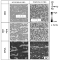
- FIG. It is an SEM image of the steel 5 for solid phase bonding and the steel 6 for solid phase bonding, an EPMA map of P, and an SEM image in which the P segregation part is superimposed. It is an SEM image and an EPMA map of P of the stirring part formed in the two-phase region of ferrite and austenite about the steel 5 for solid phase bonding and the steel 6 for solid phase bonding.
- the weathering steel for solid phase bonding of the present invention is The steel composition is mass%, C: 0.10 to 0.60%, P: Containing more than 0.035 to 1.000%, The balance is composed only of Fe and unavoidable impurities, It is a weathering steel for solid phase bonding.
- Essential additive element C 0.10 to 0.60% by mass
- the strength of the steel and solid phase joints can be sufficiently improved, and by setting it to 0.60% by mass or less, the toughness of the base metal and the stirring part is lowered. It can be suppressed.
- the content of C is preferably small, the upper limit is more preferably 0.50% by mass, and most preferably 0.30% by mass.
- a tensile strength of 490 MPa or more can be obtained by setting the carbon content to 0.30% by mass.
- Fig. 1 shows the relationship between the amount of plate thickness reduction due to corrosion and the P content of steel (Tetsuya Hosaka: “Development of highly weathering steel and adaptation to unpainted bridges”, Bridges and Foundations 6 (2002) 31-38. ).
- the weathering steel for solid-phase bonding of the present invention is premised on the use of solid-phase bonding, and since it is not necessary to consider cracks due to melt welding, the P content is more than 0.035 to 1.00 mass. It is%. Further, the addition of P can be expected to strengthen the solid solution of ferrite.
- the content of P is preferably 0.050 to 0.500% by mass, and more preferably 0.080 to 0.300% by mass.
- Fig. 2 The relationship between the C content and P content of carbon steel and the occurrence of high temperature cracks due to melt welding is shown in Fig. 2 (Ishiaki Tamaki: "Effects of carbon content and peritectic reaction on high temperature cracks of high carbon steel weld metal", Proceedings of the Welding Society, Vol. 20, No. 2, (2002), 266).
- the plot and solid line in the figure are the boundaries of cracking, and the upper right region shows that cracking occurs due to welding.
- the present invention utilizes a steel having a composition in which cracks are generated by welding as a weathering steel for solid phase bonding.
- Optional additive element Cu Over 0 to 3.00% by mass
- the protective rust is densified and the weather resistance (corrosion resistance) is improved.
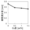
- Fig. 3 shows the relationship between the amount of plate thickness reduction due to corrosion and the Cu content of steel (Tetsuya Hosaka: “Development of highly weathering steel and adaptation to unpainted bridges”, Bridges and Foundations 6 (2002) 31-38. ). This effect is exhibited when even a small amount of Cu is added, but even if it is added in an amount of 3.00% by mass or more, no significant improvement is expected.
- the upper limit is 3.00. It is mass%.
- the amount of Cu added is preferably 0.10 to 2.00% by mass, more preferably 0.30 to 1.00% by mass.
- Mn Over 0 to 2.00 mass% It is considered that the inclusion of Mn suppresses the formation of proeutectoid ferrite and increases the amount of solid solution strengthening.
- the more preferable content of Mn is 0.25 to 0.75% by mass.
- Si Over 0 to 1.00% by mass
- Si it is possible to prevent the solid phase joint from being softened by heat, and it is expected that the effect of suppressing the formation of cementite, which reduces ductility, can be expected.
- it is 1.00% by mass or less the decrease in toughness can be suppressed.
- Ni 3.0% by mass or less
- Ni is an element that improves the strength and toughness of the base metal, but if it is contained in excess of 3.0% by mass, the HAZ portion will harden, so it should be 3.0% by mass or less. Is preferable.
- Ni forms an extremely dense oxide film on the surface, weather resistance is improved even in a beach environment where salt is flying. However, since Ni is expensive, it is preferably 3.0% by mass or less.
- Mo 1.0% by mass or less
- Mo is an element useful for improving the strength of the base material, but if it exceeds 1.0% by mass, it adversely affects the toughness, so it should be 1.0% by mass or less. preferable.
- Mo forms an extremely dense oxide film on the surface and further repairs the oxide film. In particular, the weather resistance is improved even in a beach environment where salt is flying. Further, since Mo is expensive, it is preferably 1.0% by mass or less.
- Ti 0.03% by mass or less Ti is preferably added in an amount of about 0.02% by mass because it stabilizes the oxide film formed on the surface by adding a small amount of Ti and improves weather resistance.
- B 0.0040% by mass or less B has the effect of segregating at the grain boundaries and improving the grain boundary strength. This effect is remarkable when P that makes the grain boundaries brittle is added as in the present invention. However, if it exceeds 0.0040% by mass, the toughness deteriorates, so it is preferably 0.0040% by mass or less.
- the amount of N mixed is preferably 0.010% by mass or less.
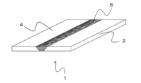
- the solid-phase bonding structure of the present invention is characterized by having the solid-phase bonding joint 1 shown in FIGS. 4 to 6.
- one aspect of the solid-phase joint formed by friction stir welding is shown in FIG. 4, and one aspect of the solid-state joint formed by friction welding is shown in FIG. 5, which is a solid-phase joint formed by linear friction welding.
- One aspect of the joint is shown in FIG.
- the material, shape, and size of the structural parts other than the solid-phase joint 1 are not particularly limited, and various conventionally known structures can be used.
- At least one of the materials to be joined (2, 4) is a weathering steel material for solid-phase bonding made of the weathering steel for solid-phase bonding of the present invention.
- the impact absorption energy of the solid phase bonding portion 6 is 90% or more of the impact absorption energy of the material to be bonded (2, 4) made of weathering steel for solid phase bonding. Since the impact absorption energy of the solid phase bonding portion 6 is 90% or more of the impact absorption energy of the material to be bonded (2, 4) made of weathering steel for solid phase bonding, the solid phase bonding structure is highly reliable.
- the impact absorption energy of the solid phase bonding portion 6 is preferably 95% or more, more preferably 100% or more of the impact absorption energy of the material to be bonded (2, 4).
- the method for measuring the shock absorption energy is not particularly limited as long as the effect of the present invention is not impaired, and various conventionally known measuring methods can be used. For example, a minute test piece is cut out from the joint and the test piece is concerned. A micro-impact test may be performed on the surface.
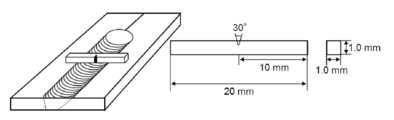
- FIG. 7 shows a schematic diagram of collecting test pieces when the solid phase bonding portion 6 is formed by friction stir welding. A notch is formed at a portion corresponding to the solid phase joint portion 6, and shock absorption energy in the region can be obtained.
- the weathering steel material for solid phase bonding of the present invention is made of the weathering steel material for solid phase bonding of the present invention, and is characterized by having a mixed structure of ferrite and fine cementite. .. Since the weathering steel for solid phase bonding of the present invention has a mixed structure composed of ferrite and fine cementite, it is possible to exhibit high strength and reliability in addition to excellent weather resistance.
- the mixing structure consisting of ferrite and fine cementite, for example, can be obtained by performing the friction stir process at the following three points A against solid bonding weathering steel of the present invention.
- the above-mentioned weathering steel for solid-phase bonding of the present invention is used as the material to be bonded (2, 4), and the bonding temperature is the same as that of the weathering steel for solid-phase bonding. It is a solid phase bonding method characterized by having A 3 points or less determined by the chemical composition.
- the solid-phase bonding weathering steel of the present invention have many content P, since it has risen A 3 points as a result, easily be performed solid-phase bonding in the following three points A it can. More specifically, when calculated using integrated thermodynamic calculation software (Thermo-cal), when the C content is 0.3% by mass, the P content is 0.1% by mass to 0.5% by mass. with mass%, the three points a can be increased 100 ° C..
- the bonding temperature of the solid phase bonding to A 3 point or less, which is determined by the chemical composition of the weathering steel for solid phase bonding, the toughness of the solid phase bonding portion 6 can be improved, and the solid phase bonding portion 6 can be improved.
- the shock absorption energy can be made higher than the shock absorption energy of the material to be joined (2, 4).
- the bonding temperature of the solid phase bonding is set to A 3 or less, which is determined by the chemical composition of the weathering steel for solid phase bonding
- the impact absorption energy of the solid phase bonding portion 6 is that of the material to be bonded (2, 4).
- the bonding temperature is A 1 point or less determined by the chemical composition of the weathering steel for solid phase bonding.
- the solid phase bonding method of the present invention it is preferable to use any one of friction stir welding, friction welding and linear friction welding.
- the bonding temperature it is necessary to control the bonding temperature, but by using these solid-phase bonding methods, the bonding temperature can be accurately determined.
- the joining temperature can be controlled by the shape, size and material of the tool, joining speed, joining load, tool rotation speed, and the like.
- the bonding temperature can be controlled by the bonding pressure applied to the interface to be bonded.
- the joining temperature can be lowered by using a tool material having a low affinity with the material to be welded, increasing the joining speed, reducing the joining load and the tool rotation speed, and friction welding.
- the bonding temperature can be lowered by increasing the bonding pressure applied to the interface to be bonded. It is also possible to lower the junction temperature by using external cooling with liquid CO 2 , liquid nitrogen, water and various gases.
- the weathering steel for solid phase bonding the weathering steel for solid phase bonding, the weathering steel for solid phase bonding, the solid phase bonding structure, and the solid phase bonding method of the present invention will be further described in Examples, but the present invention is limited to these Examples. It is not something that is done.
- Example 1 A steel ingot ( ⁇ 35 ⁇ 20 to 25 h) having the composition shown in Table 1 was prepared by high-frequency melting, and a steel plate having a thickness of 3 mm (weathering steel material 1 for solid phase bonding) was formed by hot rolling at 900 ° C. Obtained. The hot-rolled steel sheet was held at 900 ° C. for 10 minutes and then air-cooled (normalized). The values shown in Table 1 are mass%.
- a cemented carbide tool (the probe does not have a screw) having a shape of a shoulder diameter of 15 mm, a probe diameter of 6 mm, and a probe length of 2.9 mm was used for the obtained steel sheet, and the tool rotation speed: 400 rpm, joining speed. Friction stir welding was performed under the conditions of: 150 mm / min, joining load: 2.5 ton, tool advance angle: 3 °, and joining atmosphere: Ar.
- Example 2 A steel sheet (Steel 2 for solid phase bonding) was obtained in the same manner as in Example 1 except that the composition of Example 2 shown in Table 1 was used. Further, friction stir welding was performed in the same manner as in Example 1. In addition, for comparison, TIG welding was performed under the conditions of welding current: 130 A and welding speed: 300 mm / min.
- Example 3 A steel sheet (Steel 2 for solid phase bonding) was obtained in the same manner as in Example 1 except that the composition of Example 3 shown in Table 1 was used. Further, friction stir welding was performed in the same manner as in Example 1 except that the tool rotation speed was 100 rpm and the joining speed was 100 mm / min.
- Example 4 Using the composition of Example 4 shown in Table 1, a steel sheet (implemented solid phase) was used in the same manner as in Example 1 except that a tempering treatment (holding at 500 ° C. for 30 minutes and then quenching) was added after the normalizing treatment. A steel for joining 4) was obtained. Further, friction stir welding was performed in the same manner as in Example 3.
- Example 5 >> A steel ingot ( ⁇ 35 ⁇ 20 to 25 h) having the composition of Example 5 shown in Table 2 was prepared by high-frequency melting, and a steel plate having a thickness of 3 mm was produced by hot rolling at 1000 ° C. (Steel 5 for solid phase bonding). ) was obtained. The hot-rolled steel sheet was held at 1000 ° C. for 10 minutes and then air-cooled (normalized). The values shown in Table 2 are mass%.
- a cemented carbide tool (the probe does not have a screw) having a shape of a shoulder diameter of 15 mm, a probe diameter of 6 mm, and a probe length of 2.9 mm is used for the obtained steel plate, and the tool advance angle is 3 in an Ar atmosphere. Friction stir welding was performed at °. Here, the high temperature bonding conditions the junction temperature exceeds three points A steel, tool rotation speed: 400 rpm, welding speed: a 150 mm / min, bonding load suitable frictional heat in contact with the surface of the shoulder is steel sheet Adjusted to occur.
- the tool rotation speed is 80 rpm and the joining speed is 150 mm / min, and the joining load is the appropriate frictional heat when the shoulder comes into contact with the surface of the steel sheet. Adjusted to occur.
- Example 6 A steel sheet (Steel 6 for solid phase bonding) was obtained in the same manner as in Example 5 except that the composition of Example 6 shown in Table 2 was used. Further, friction stir welding was performed in the same manner as in Example 5.
- Example 7 Using the composition of Example 7 shown in Table 2, the steel plate (steel for solid phase bonding) was obtained in the same manner as in Example 5 except that the hot rolling temperature was 950 ° C and the subsequent holding temperature was 900 ° C. 7) was obtained. Further, using a cemented carbide tool (the probe does not have a screw) having a shape of a shoulder diameter of 15 mm, a probe diameter of 6 mm, and a probe length of 2.9 mm for the obtained steel plate, the tool advances in an Ar atmosphere. Friction stir welding was performed at an angle of 3 °.
- the tool rotation speed is 100 rpm and the bonding speed is 100 mm / min, and the bonding load is the appropriate frictional heat when the shoulder comes into contact with the surface of the steel sheet.
- Example 8 A steel sheet (Steel 8 for solid phase bonding) was obtained in the same manner as in Example 7 except that the composition of Example 8 shown in Table 2 was used. Further, friction stir welding was performed in the same manner as in Example 7.
- Example 9 A steel sheet (Steel 9 for solid phase bonding) was obtained in the same manner as in Example 7 except that the composition of Example 9 shown in Table 2 was used. Further, friction stir welding was performed in the same manner as in Example 7.
- Example 10 A steel sheet (Steel 10 for solid phase bonding) was obtained in the same manner as in Example 7 except that the composition of Example 10 shown in Table 2 was used. Further, friction stir welding was performed in the same manner as in Example 7.
- Comparative Example 1 As the test material, SMA490AW, which is an existing weathering steel standardized by JIS, was used. SMA490AW has the composition shown as Comparative Example 1 in Table 3, but the addition of C and P is suppressed. The values shown in Table 3 are mass%. Further, friction stir welding was performed using the same joining conditions as in Example 7.
- Comparative Example 2 As the test material, SPA-H, which is an existing weathering steel standardized by JIS, was used. SPA-H has the composition shown as Comparative Example 2 in Table 3, but the addition of C and P is suppressed. Further, friction stir welding was performed using the same joining conditions as in Example 7.
- Comparative Example 3 Using the composition of Comparative Example 3 shown in Table 3, a steel sheet (steel for comparative solid phase bonding) was used in the same manner as in Example 5 except that the hot rolling temperature was 950 ° C and the subsequent holding temperature was 900 ° C. 3) was obtained.
- the comparative solid phase bonding steel 3 contains 0.3% by mass of C, while the addition of P is suppressed. Further, friction stir welding was performed using the same joining conditions as in Example 7.
- Micro-impact test The fracture toughness of the base metal and joints was evaluated by calculating the absorbed energy by the micro-impact test.
- the micro-impact test piece shown in FIG. 7 was cut out from the base material and the friction stir welding portion.
- the notch of the test piece was set to the center of the stirring region, and the dimensions of the test piece were length: 20 mm, thickness: 0.5 mm, width: 0.5 mm, and notch: 0.1 mm.
- the measurement was performed at room temperature with the puncher speed set to 1 m / s, and the absorbed energy was calculated by integrating the obtained load displacement curve.
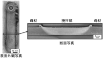
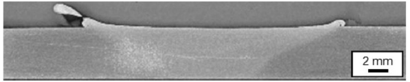
- FIG. 8 shows a photograph of the surface appearance and a photograph of the cross section of the steel 2 for solid phase welding, which was subjected to friction stir welding in Example 2. No defects such as cracks were observed on the surface and cross section, and it can be seen that a good stirring portion (solid phase bonding portion) was formed.
- FIG. 9 shows a microstructure photograph of the base material and the stirring portion of the solid phase bonding steel 2.
- the base material has a structure consisting of ferrite and pearlite, and the stirring part has a structure consisting of bainite and martensite.
- the results, the junction temperature of the friction stir welding in Example 2 have shown that higher than 3 points A.
- the horizontal distribution of Vickers hardness in the vicinity of the stirring portion is shown in FIG. 10, and the hardness of the stirring portion is higher than that of the base metal due to the formation of the transformed structure.
- the hardness of the base material is about 180 HV, which means that the base material has a tensile strength of about 540 MPa.
- the base material of the steel 2 for solid phase bonding was 30.7 N ⁇ mm and the stirring part was 6.7 N ⁇ mm. ..
- the impact absorption energy of the base metal of the solid-state bonding steel 2 is about the same as the impact absorption energy of the weathering-resistant hot-rolled steel sheet for welded structures that guarantees weldability, and contains a relatively large amount of C and P. Despite this, it has good toughness.
- the stirring part also maintains a certain amount of shock absorption energy, but the value is lower than that of the base metal.
- FIG. 11 shows a photograph of the surface appearance of the steel 2 for solid phase welding in which TIG welding was performed in Example 2, and cracks have occurred in the regions surrounded by circles and squares. An enlarged photograph of the area surrounded by the square is shown in FIG.
- FIG. 13 shows a cross-sectional photograph of the steel 3 for solid phase welding, which was subjected to friction stir welding in Example 3. It can be seen that a good stirring portion (solid phase bonding portion) without defects is formed even when the bonding temperature is lowered.
- FIG. 14 shows a microstructure photograph of the stirring portion of the steel for solid phase bonding.
- Has a small amount of martensite comprised of fine ferrite and pearlite containing tissue the result means that the highest temperature of the friction stir welding is equal to or less than 3 points A (2-phase region of ferrite and austenite) doing.
- the horizontal distribution of the Vickers hardness in the vicinity of the stirring portion of the implementation solid phase bonding steel 3 is shown in FIG. 15 (for comparison, the Vickers hardness in the vicinity of the stirring portion of the implementation solid phase bonding steel 2 is also shown).
- the increase in hardness of the agitated portion of the steel 3 for solid phase bonding is smaller due to the suppression of the formation of the transformation structure, and is lower than that of the agitated portion of the steel 2 for solid phase bonding.
- impact absorption energy of the stirring section according Solid State Welding steel 3 is 36.0N ⁇ mm, even when the increasing number content, such as C and P, solid phase bonding in the following three points A It can be seen that a higher shock absorption energy than that of the base material can be obtained by applying.
- the impact absorption energy of the base metal of the steel for solid phase bonding 3 was about 30 N ⁇ mm, which was the same as that for the steel 2 for solid phase bonding.
- FIG. 16 shows the fracture surface of the micro-impact test piece of the stirring portion of the steel for solid-phase bonding 2 and the steel 3 for solid-phase bonding.
- FIG. 17 shows a cross-sectional photograph of the steel 1 for solid phase welding, which was subjected to friction stir welding in Example 1. No defects such as cracks were observed, and it can be seen that a good stirring portion (solid phase bonding portion) was formed. Further, when the shock absorption energy was obtained from the area of the load displacement curve obtained in the micro-impact test, the base material of the steel 1 for solid phase bonding was 33.1 N ⁇ mm and the stirring part was 35.7 N ⁇ mm. there were. When the content of such C and P is relatively small, the impact absorption energy of the joint be solid phase bonding temperature higher than the 3-point A may be at least the base material.
- the impact absorption energy of the base metal was 19.4 N ⁇ mm, and the impact absorption energy of the stirring portion was 36.0 N ⁇ mm. Even if the tempering treatment impact absorption energy of the base metal was reduced, the solid phase bonding temperature can impart a high impact energy absorption to a solid junction is set to lower than or equal to 3 points A.
- FIG. 18 shows an SEM image of the implementation solid-phase bonding steel 5 and the implementation solid-phase bonding steel 6, an EPMA map of P, and an SEM image in which the P segregation portion is superimposed.
- the base metal structure of both the solid-phase bonding steel 5 and the solid-phase bonding steel 6 is composed of ferrite and pearlite.
- the steel 5 for solid phase bonding also has a layered P segregation portion extending in the TD direction similar to the steel 6 for solid phase bonding.
- P segregation in the matrix of the embodiment Solid State Welding steel 5, similarly as in the solid-phase bonding steel 6, maintained at a temperature of segregation area is more than three points A during hot rolling caused by solidification segregation It is considered that it was formed by being rolled and stretched. It can be seen that the P concentration of the segregated portion is lower in the steel 5 for solid phase bonding.
- FIG. 19 shows an SEM image of a stirring portion formed by friction stir welding in a two-phase region of ferrite and austenite and an EPMA map of P for the steel 5 for solid phase welding and the steel 6 for solid phase welding.
- the stirring portion has a structure mainly composed of ferrite and pearlite. Further, it can be seen that in any of the stirring portions, P is dispersed in ferrite due to the stirring effect of friction stir welding and is homogenized as compared with the base material.
- FIG. 20 shows an SEM image of the base material and the stirring portion of the steel 5 for solid phase bonding and the steel 6 for solid phase bonding.
- the grain size of ferrite was 48.6 ⁇ m for the steel 5 for solid phase bonding and 23.3 ⁇ m for the steel 6 for solid phase bonding, and the crystal grain size was significantly reduced by increasing the amount of P added. ing. It is considered that this is because the moving speed of the transformation interface and the growth rate of ferrite decreased due to the solution drag effect due to the increase in the amount of P added.
- the pearlite fraction was 8.3% for the steel 5 for solid phase bonding and 3.6% for the steel 6 for solid phase bonding, which decreased with the addition of P.
- both the solid-phase bonding steel 5 and the solid-phase bonding steel 6 are mainly ferrite ( ⁇ ) and pearlite, and martensite is partially mixed. It is an organization that does.
- the crystal grain size of ferrite is 11.7 ⁇ m in the steel 5 for solid phase bonding and 7.3 ⁇ m in the steel 6 for solid phase bonding, and the steel 6 for solid phase bonding is slightly finer.
- both the solid-phase bonding steel 5 and the solid-phase bonding steel 6 have a structure composed of ferrite ( ⁇ ) and spherical cementite ( ⁇ ).
- the grain size of ferrite is 1.37 ⁇ m for the steel for solid phase welding 5 and 2.47 ⁇ m for the steel 6 for solid phase bonding. It is significantly finer by friction stir welding at A point 1 or less, and the solid phase bonding is performed.
- the steel 5 is slightly finer.
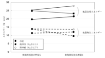
- the crack generation energy and the crack propagation energy were calculated from the area of the load displacement curve obtained in the micro-impact test of the base material and the stirring portion of the implementation solid-phase bonding steel 5 and the implementation solid-phase bonding steel 6. The obtained results are shown in FIG.
- the stirring part evaluates the case where the joining temperature is A 3 points or more and the case where A 1 point or less.
- the sum of the crack generation energy and the crack propagation energy is the shock absorption energy.
- the crack propagation energy of the stirring portion is higher than that of the base metal.
- the bonding temperature in the exemplary solid-phase bonding steel 6 is equal to or larger than three points A has a value lower than the base metal, the absorbed energy also added crack propagation energy, and the matrix Similar values are obtained.
- FIG. 22 shows SEM images of the base material and the stirring portion of the implemented solid phase bonding steel 7 to the implemented solid phase bonding steel 10.
- both the base material and the stirring part have a structure mainly composed of ferrite and pearlite, and the structure of the stirring part is remarkable as compared with the base material. It has been refined to.
- ferrite distributed in layers parallel to the TD direction is observed. This ferrite is not a crystal grain elongated in layers, but an aggregate in which equiaxed grains are distributed in layers. This layered ferrite aggregate increases as the amount of P added increases.
- FIG. 23 shows the relationship between the shock absorption energy and the amount of P added to the base material and the stirring portion of the implemented solid phase bonding steel 7 to the implemented solid phase bonding steel 10.
- the shock absorption energy of both the base material and the stirring part decreases as the amount of P added increases, but it can be seen that the value of the stirring part is higher than that of the base material in any case of the amount of P added. ..
- the impact absorption energies of the base materials of the comparative solid-phase bonding steel 1 the comparative solid-phase bonding steel 2 and the comparative solid-phase bonding steel 3 were measured by a micro-impact test, they were 31.8 N ⁇ mm and 33.1 N ⁇ , respectively. It was mm and 28.7 N ⁇ mm.
- the stirring portions formed at the joining temperature of A 3 points or more were 38.2 N ⁇ mm, 35.7 N ⁇ mm and 18.2 N ⁇ mm, respectively.
- the addition amounts of C and P are suppressed in order to ensure weldability and reliability of the welded portion, and the impact absorption energy in the stirring portion is suppressed. No decrease is observed.
- the comparative solid phase bonding steel 3 containing 0.3 wt% C impact absorption energy of the agitating portion formed at a junction temperature of more than three points A is lower than the base metal.
Landscapes
- Chemical & Material Sciences (AREA)
- Engineering & Computer Science (AREA)
- Mechanical Engineering (AREA)
- Materials Engineering (AREA)
- Metallurgy (AREA)
- Organic Chemistry (AREA)
- Pressure Welding/Diffusion-Bonding (AREA)
- Heat Treatment Of Steel (AREA)
Abstract
Description
鋼組成が、質量%で、
C:0.10~0.60%、
P:0.035超~1.000%、を含有し、
残部がFe及び不可避不純物のみの組成であること、
を特徴とする固相接合用耐候性鋼を提供する。
本発明の固相接合用耐候性鋼は、
鋼組成が、質量%で、
C:0.10~0.60%、
P:0.035超~1.000%、を含有し、
残部がFe及び不可避不純物のみの組成であること、
を特徴とする固相接合用耐候性鋼である。
C:0.10~0.60質量%
炭素含有量を0.10質量%以上とすることで鋼及び固相接合部の強度を十分に向上させることができ、0.60質量%以下とすることで母材及び攪拌部の靭性低下を抑制することができる。所望の引張強度が得られる限りにおいて、Cの含有量は少なくすることが好ましく、上限を0.50質量%とすることがより好ましく、0.30質量%とすることが最も好ましい。例えば、その他の添加元素や組織にも依存するが、炭素含有量を0.30質量%とすることで、490MPa以上の引張強度を得ることができる。
P含有量が0.5質量%程度までは保護性さびの緻密化等によって鋼の耐食性(耐候性)が明確に向上し、1.0質量%程度までは当該効果が増大することが知られている。図1に腐食による板厚減少量と鋼のP含有量の関係を示す(保坂鐵矢:“高耐候性鋼の開発と無塗装橋梁への適応”,橋梁と基礎 6 (2002) 31-38)。本発明の固相接合用耐候性鋼は固相接合を用いることを前提としており、溶融溶接に伴う割れを考慮する必要がないことから、Pの含有量が0.035超~1.00質量%となっている。また、Pの添加により、フェライトの固溶強化も期待できる。ここで、Pの含有量は0.050~0.500質量%とすることが好ましく、0.080~0.300質量%とすることがより好ましい。
Cu:0超~3.00質量%
適量のCuを含有することで、保護性さびが緻密化し、耐候性(耐食性)が向上する。図3に腐食による板厚減少量と鋼のCu含有量の関係を示す(保坂鐵矢:“高耐候性鋼の開発と無塗装橋梁への適応”,橋梁と基礎 6 (2002) 31-38)。当該効果はCuが僅かでも添加されれば発現するが、3.00質量%以上添加しても大きな向上は期待されないことに加え、母材及びHAZ部が硬化するため、上限値が3.00質量%となっている。Cuの添加量は0.10~2.00質量%とすることが好ましく、0.30~1.00質量%とすることがより好ましい。
Mnを含むことで初析フェライトの生成が抑制されると共に、固溶強化量が増大すると考えられる。なお、Mnのより好ましい含有量は0.25~0.75質量%である。
Siを含有させることで固相接合部が熱によって軟化することを抑制することができ、延性を低下させるセメンタイトの生成を抑制する効果も期待できる。一方で、1.00質量%以下とすることで、靭性の低下を抑制することができる。
Crを0超~2.00質量%含有することで、固相接合部の強度及び延性を改善することができ、靭性を向上させることができる。特に、パーライト組織のラメラ間隔を微細化し、強度を向上させる効果がある。また、Crは表面に緻密な酸化膜を形成するため、耐侯性も向上する。
Niは、母材の強度と靱性を向上させる元素であるが、3.0質量%を超えて含有するとHAZ部が硬化するため、3.0質量%以下とすることが好ましい。また、Niは表面に極めて緻密な酸化膜を形成するため、塩分が飛来する海浜環境においても耐候性が向上する。しかし、Niは高価であることからも、3.0質量%以下とすることが好ましい。
Moは、母材の強度向上に有用な元素であるが、1.0質量%を超えると靱性に悪影響を及ぼすことから、1.0質量%以下とすることが好ましい。また、Moは表面に極めて緻密な酸化膜を形成し、さらに酸化膜を修復する。特に、塩分が飛来する海浜環境においても耐候性が向上する。また、Moは高価であることからも、1.0質量%以下とすることが好ましい。
Tiは、微量の添加で表面に形成される酸化膜を安定化するため、耐候性を向上することから、0.02質量%程度の添加が好ましい。
Bは、粒界に偏析して粒界強度を向上する効果がある。当該効果は、本発明のように粒界を脆くするPが添加する場合に著しい。しかし、0.0040質量%を超えると靱性を劣化させることから、0.0040質量%以下とすることが好ましい。
本発明の固相接合構造物は、図4~図6に示す固相接合継手1を有することを特徴としている。ここで、摩擦攪拌接合によって形成された固相接合継手の一態様を図4に、摩擦圧接によって形成された固相接合継手の一態様を図5に、線形摩擦接合によって形成された固相接合継手の一態様を図6に、それぞれ示している。固相接合継手1以外の構造部に関する材質、形状及びサイズは特に限定されず、従来公知の種々の構造物とすることができる。
本発明の固相接合用耐候性鋼材は、本発明の固相接合用耐候性鋼からなり、フェライトと微細セメンタイトからなる混合組織を有することを特徴としている。本発明の固相接合用耐候性鋼がフェライトと微細セメンタイトからなる混合組織を有することで、優れた耐候性に加えて、高い強度と信頼性を発現することができる。なお、フェライトと微細セメンタイトからなる混合組織は、例えば、本発明の固相接合用耐候性鋼に対してA3点以下での摩擦攪拌プロセスを施すことで得ることができる。
本発明の固相接合方法は、上述の本発明の固相接合用耐候性鋼を被接合材(2,4)とし、接合温度を固相接合用耐候性鋼の化学組成で決定されるA3点以下とすること、を特徴とする固相接合方法である。ここで、本発明の固相接合用耐候性鋼はPの含有量が多く、その結果としてA3点が上昇していることから、容易にA3点以下での固相接合を行うことができる。より具体的には、統合型熱力学計算ソフトウェア(Thermo-calc)を用いて計算したところ、C含有量を0.3質量%とした場合、P含有量を0.1質量%から0.5質量%とすることで、A3点を100℃上昇させることができる。
高周波溶解により表1に示す組成を有する鋼のインゴット(φ35×20~25h)を作製し、900℃の熱間圧延にて板厚を3mmの鋼板(実施固相接合用耐候性鋼材1)を得た。熱間圧延後の鋼板は900℃で10分間保持した後、空冷した(焼ならし処理)。なお、表1に示す値は質量%である。

表1に示す実施例2の組成を用いた以外は実施例1と同様にして、鋼板(実施固相接合用鋼2)を得た。また、実施例1と同様にして、摩擦攪拌接合を施した。加えて、比較として、溶接電流:130A、溶接速度:300mm/minの条件でTIG溶接を施した。
表1に示す実施例3の組成を用いた以外は実施例1と同様にして、鋼板(実施固相接合用鋼2)を得た。また、ツール回転速度:100rpm、接合速度:100mm/minとしたこと以外は実施例1と同様にして、摩擦攪拌接合を施した。
表1に示す実施例4の組成を用い、焼ならし処理の後に焼戻し処理(500℃で30分保持した後に急冷)を加えたこと以外は実施例1と同様にして、鋼板(実施固相接合用鋼4)を得た。また、実施例3と同様にして、摩擦攪拌接合を施した。
高周波溶解により表2に示す実施例5の組成を有する鋼のインゴット(φ35×20~25h)を作製し、1000℃の熱間圧延にて板厚を3mmの鋼板(実施固相接合用鋼5)を得た。熱間圧延後の鋼板は1000℃で10分間保持した後、空冷した(焼ならし処理)。なお、表2に示す値は質量%である。
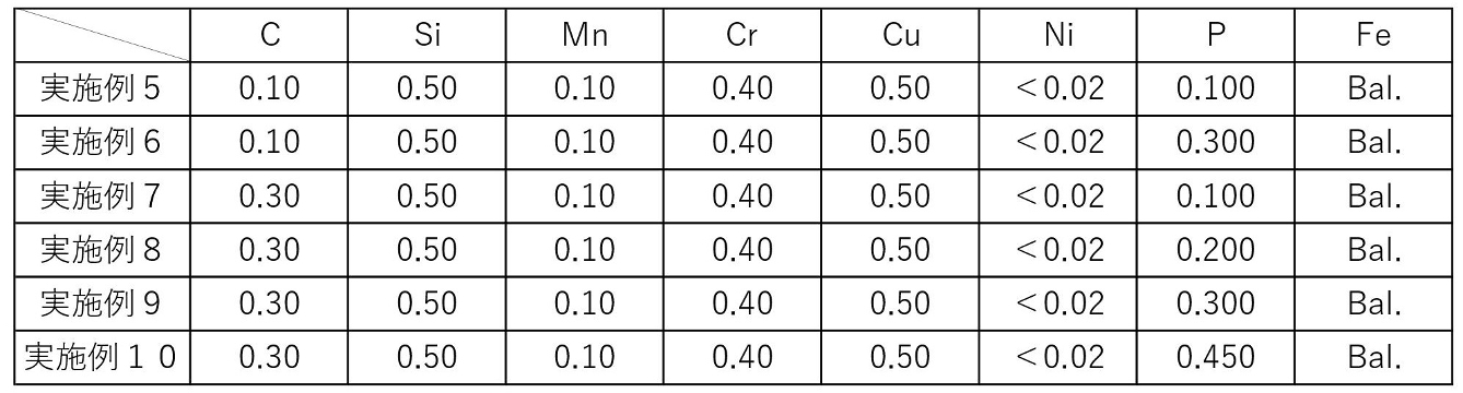
表2に示す実施例6の組成を用いた以外は実施例5と同様にして、鋼板(実施固相接合用鋼6)を得た。また、実施例5と同様にして、摩擦攪拌接合を施した。
表2に示す実施例7の組成を用い、熱間圧延の温度を950℃とし、その後の保持温度を900℃としたこと以外は実施例5と同様にして、鋼板(実施固相接合用鋼7)を得た。また、得られた鋼板に対し、ショルダ径15mm、プローブ径6mm、プローブ長2.9mmの形状を有する超硬合金製ツール(プローブにネジを有していない)を用い、Ar雰囲気下でツール前進角3°にて摩擦攪拌接合を行った。ここで、接合温度が鋼材のA3点を超える高温接合条件については、ツール回転速度:400rpm、接合速度:150mm/minとし、接合荷重はショルダが鋼板の表面に当接して適当な摩擦熱が発生するように調節した。また、接合温度がフェライトとオーステナイトの2相域となる低温接合条件については、ツール回転速度:100rpm、接合速度:100mm/minとし、接合荷重はショルダが鋼板の表面に当接して適当な摩擦熱が発生するように調節した。
表2に示す実施例8の組成を用いた以外は実施例7と同様にして、鋼板(実施固相接合用鋼8)を得た。また、実施例7と同様にして、摩擦攪拌接合を施した。
表2に示す実施例9の組成を用いた以外は実施例7と同様にして、鋼板(実施固相接合用鋼9)を得た。また、実施例7と同様にして、摩擦攪拌接合を施した。
表2に示す実施例10の組成を用いた以外は実施例7と同様にして、鋼板(実施固相接合用鋼10)を得た。また、実施例7と同様にして、摩擦攪拌接合を施した。
供試材として、JISで規格化された既存の耐候性鋼であるSMA490AWを用いた。SMA490AWは表3の比較例1として示す組成を有しているが、CとPの添加が抑制されている。なお、表3に示す値は質量%である。また、実施例7と同様の接合条件を用いて摩擦攪拌接合を施した。

供試材として、JISで規格化された既存の耐候性鋼であるSPA-Hを用いた。SPA-Hは表3の比較例2として示す組成を有しているが、CとPの添加が抑制されている。また、実施例7と同様の接合条件を用いて摩擦攪拌接合を施した。
表3に示す比較例3の組成を用い、熱間圧延の温度を950℃とし、その後の保持温度を900℃としたこと以外は実施例5と同様にして、鋼板(比較固相接合用鋼3)を得た。比較固相接合用鋼3は0.3質量%のCを含む一方で、Pの添加が抑制されている。また、実施例7と同様の接合条件を用いて摩擦攪拌接合を施した。
(1)組織観察
摩擦攪拌接合方向に対して垂直に攪拌部を含む領域を切り出し、断面を研磨及び腐食(4%ナイタール)した後、光学顕微鏡を用いて組織観察を行った。なお、研磨にはエメリー紙(#600~#3000)及びダイヤモンドペースト(粒度3μm及び1μm)を用いた。また、母材観察用の試料も同様に準備した。また、走査電子顕微鏡(SEM,JEOL JSM-7001FA)を用いてより詳細に微細組織を観察した。P及びCの分布状況については、電子線マクロアナライザ(EPMA)を用いて評価した。
(1)と同様にして断面試料を作製し、攪拌部近傍におけるビッカース硬度の水平分布を測定した。微小硬度計FM-300(株式会社フューチュアテック製)を用い、測定荷重を100gf、保持時間を15sとして測定を行った。
微小衝撃試験によって吸収エネルギーを算出することで、母材及び接合部の破壊靭性を評価した。なお、図7に示す微小衝撃試験片を母材及び摩擦攪拌接合部から切り出した。試験片のノッチは攪拌領域の中央になるようにし、試験片の寸法は長さ:20mm、厚さ:0.5mm、幅:0.5mm、ノッチ:0.1mmとした。なお、測定はパンチャー速度を1m/sとして室温で行い、得られた荷重変位曲線の積分により吸収エネルギーを算出した。
2,4・・・被接合材、
6・・・固相接合部。
Claims (13)
- 鋼組成が、質量%で、
C:0.10~0.60%、
P:0.035超~1.000%、を含有し、
残部がFe及び不可避不純物のみの組成であること、
を特徴とする固相接合用耐候性鋼。 - 更に、質量%で、
Cu:0超~3.00%を含有すること、
を特徴とする請求項1に記載の固相接合用耐候性鋼。 - 更に、質量%で、
Mn:0超~2.00%を含有すること、
を特徴とする請求項1又は2に記載の固相接合用耐候性鋼。 - 更に、質量%で、
Si:0超~1.00%を含有すること、
を特徴とする請求項1~3のうちのいずれかに記載の固相接合用耐候性鋼。 - 更に、質量%で、
Cr:0超~2.00%を含有すること、
を特徴とする請求項1~4のうちのいずれかに記載の固相接合用耐候性鋼。 - 更に、質量%で、
Ni:0超~3.00%を含有すること、
を特徴とする請求項1~5のうちのいずれかに記載の固相接合用耐候性鋼。 - 更に、質量%で、
Mo:0超~1.00%を含有すること、
を特徴とする請求項1~6のうちのいずれかに記載の固相接合用耐候性鋼。 - 更に、質量%で、
Ti:0超~0.03%を含有すること、
を特徴とする請求項1~7のうちのいずれかに記載の固相接合用耐候性鋼。 - 請求項1~8のうちのいずれかに記載の固相接合用耐候性鋼の固相接合部を有する接合構造物であって、
前記固相合部の衝撃吸収エネルギーが前記固相接合用耐候性鋼の衝撃吸収エネルギーの90%以上であること、
を特徴とする固相接合構造物。 - 請求項1~8のうちのいずれかに記載の固相接合用耐候性鋼からなり、
フェライトと微細セメンタイトからなる混合組織を有すること、
を特徴とする固相接合用耐候性鋼材。 - 請求項1~8のうちのいずれかに記載の固相接合用耐候性鋼からなる固相接合用耐候性鋼材に固相接合する方法であって、
接合温度を前記固相接合用耐候性鋼の化学組成で決定されるA3点以下とすること、
を特徴とする固相接合方法。 - 前記接合温度を前記固相接合用耐候性鋼の化学組成で決定されるA1点以下とすること、
を特徴とする請求項11に記載の固相接合方法。 - 摩擦攪拌接合、摩擦圧接及び線形固相接合のうちのいずれかを用いること、
を特徴とする請求項11又は12に記載の固相接合方法。
Priority Applications (3)
| Application Number | Priority Date | Filing Date | Title |
|---|---|---|---|
| US17/435,875 US12234535B2 (en) | 2019-03-12 | 2020-02-20 | Weathering steel for solid-state welding, weathering steel material for solid-state welding, solid-state welded structure and solid-state welding method |
| JP2021504877A JP7490251B2 (ja) | 2019-03-12 | 2020-02-20 | 固相接合用耐候性鋼、固相接合用耐候性鋼材、固相接合構造物及び固相接合方法 |
| CN202080020607.XA CN113574195A (zh) | 2019-03-12 | 2020-02-20 | 固相接合用耐候性钢、固相接合用耐候性钢材、固相接合结构物和固相接合方法 |
Applications Claiming Priority (2)
| Application Number | Priority Date | Filing Date | Title |
|---|---|---|---|
| JP2019044619 | 2019-03-12 | ||
| JP2019-044619 | 2019-03-12 |
Publications (1)
| Publication Number | Publication Date |
|---|---|
| WO2020184124A1 true WO2020184124A1 (ja) | 2020-09-17 |
Family
ID=72427363
Family Applications (1)
| Application Number | Title | Priority Date | Filing Date |
|---|---|---|---|
| PCT/JP2020/006684 Ceased WO2020184124A1 (ja) | 2019-03-12 | 2020-02-20 | 固相接合用耐候性鋼、固相接合用耐候性鋼材、固相接合構造物及び固相接合方法 |
Country Status (4)
| Country | Link |
|---|---|
| US (1) | US12234535B2 (ja) |
| JP (1) | JP7490251B2 (ja) |
| CN (1) | CN113574195A (ja) |
| WO (1) | WO2020184124A1 (ja) |
Cited By (5)
| Publication number | Priority date | Publication date | Assignee | Title |
|---|---|---|---|---|
| JPWO2021187473A1 (ja) * | 2020-03-18 | 2021-09-23 | ||
| JP7231798B1 (ja) * | 2021-08-31 | 2023-03-01 | Jfeスチール株式会社 | 摩擦攪拌点接合継手およびその製造方法、ならびに、摩擦攪拌点接合方法 |
| JP7231797B1 (ja) * | 2021-08-31 | 2023-03-01 | Jfeスチール株式会社 | 摩擦攪拌点接合継手およびその製造方法、ならびに、摩擦攪拌点接合方法 |
| WO2023032515A1 (ja) * | 2021-08-31 | 2023-03-09 | Jfeスチール株式会社 | 摩擦攪拌点接合継手およびその製造方法、ならびに、摩擦攪拌点接合方法 |
| WO2023032514A1 (ja) * | 2021-08-31 | 2023-03-09 | Jfeスチール株式会社 | 摩擦攪拌点接合継手およびその製造方法、ならびに、摩擦攪拌点接合方法 |
Citations (1)
| Publication number | Priority date | Publication date | Assignee | Title |
|---|---|---|---|---|
| JP2009161165A (ja) * | 2007-12-05 | 2009-07-23 | Honda Motor Co Ltd | 車両用強度部材 |
Family Cites Families (26)
| Publication number | Priority date | Publication date | Assignee | Title |
|---|---|---|---|---|
| US6244161B1 (en) * | 1999-10-07 | 2001-06-12 | Cummins Engine Company, Inc. | High temperature-resistant material for articulated pistons |
| CN1132958C (zh) * | 2001-10-17 | 2003-12-31 | 武汉钢铁(集团)公司 | 高性能耐火耐候建筑用钢及其生产方法 |
| CN100422372C (zh) * | 2005-10-10 | 2008-10-01 | 燕山大学 | 热轧双相耐候钢板及其制造方法 |
| JP5040206B2 (ja) * | 2006-07-26 | 2012-10-03 | Jfeスチール株式会社 | 摩擦撹拌接合用の低合金構造用鋼 |
| CN100507055C (zh) * | 2006-08-31 | 2009-07-01 | 宝山钢铁股份有限公司 | 屈服强度700MPa级耐大气腐蚀钢及其制造方法 |
| CN100535134C (zh) * | 2007-06-27 | 2009-09-02 | 攀钢集团攀枝花钢铁研究院 | 含铜钢加热方法及其生产的含铜钢 |
| JP5060246B2 (ja) * | 2007-11-02 | 2012-10-31 | 住友金属工業株式会社 | 鋼板のアレスト特性評価方法およびアレスト特性評価用鋼板 |
| CN102066597B (zh) * | 2008-06-13 | 2013-03-06 | 株式会社神户制钢所 | 异种材料接合用钢材、异种材料接合体及异种材料接合方法 |
| CN101487105A (zh) * | 2009-02-27 | 2009-07-22 | 东北大学 | 一种表面负偏析磷的高磷耐候钢铸轧薄带及其制备方法 |
| CN101845599B (zh) * | 2009-03-24 | 2012-05-30 | 宝山钢铁股份有限公司 | 一种耐候钢及其制造方法 |
| CN101876032B (zh) * | 2009-12-26 | 2012-08-29 | 舞阳钢铁有限责任公司 | 一种耐候桥梁用高强度钢板及其生产方法 |
| CN102534417B (zh) * | 2012-02-08 | 2014-02-26 | 东北大学 | 一种含Mo的高性能桥梁耐候钢的制备方法 |
| CN103305759B (zh) | 2012-03-14 | 2014-10-29 | 宝山钢铁股份有限公司 | 一种薄带连铸700MPa级高强耐候钢制造方法 |
| KR101505381B1 (ko) * | 2012-04-06 | 2015-03-23 | 제이에프이 스틸 가부시키가이샤 | 강판의 마찰 교반 접합 방법 |
| CN103361568B (zh) * | 2013-05-28 | 2016-06-22 | 国际冷弯型钢学会有限公司 | 一种耐火耐候建筑钢材及其制造方法 |
| WO2015015738A1 (ja) * | 2013-08-02 | 2015-02-05 | Jfeスチール株式会社 | 高強度高ヤング率鋼板およびその製造方法 |
| EP3067148B1 (en) * | 2013-11-07 | 2022-09-07 | JFE Steel Corporation | Friction stir welding method for high-strength steel sheets or plates |
| MX394289B (es) * | 2015-02-27 | 2025-03-21 | Jfe Steel Corp | Lámina de acero laminada en frío de alta resistencia y método para fabricar la misma. |
| EP3293279B1 (en) * | 2015-05-07 | 2020-03-25 | Nippon Steel Corporation | High-strength steel plate and production method therefor |
| CN107848065B (zh) * | 2015-07-31 | 2020-03-13 | 国立大学法人大阪大学 | 摩擦焊接方法 |
| DE102016211411A1 (de) * | 2016-06-24 | 2017-12-28 | Thyssenkrupp Ag | Fahrzeugrad und Verwendung |
| CN107267883B (zh) * | 2017-05-31 | 2019-05-24 | 武汉钢铁有限公司 | 一种屈服强度≥550MPa铁路集装箱用耐候钢及生产方法 |
| CN107699790A (zh) * | 2017-09-20 | 2018-02-16 | 天津钢管集团股份有限公司 | 耐候无缝钢管钢种及无缝钢管制造方法 |
| CN111902551A (zh) * | 2017-11-03 | 2020-11-06 | 艾普伦 | 马氏体不锈钢及其制造方法 |
| JP6566168B1 (ja) * | 2017-11-29 | 2019-08-28 | Jfeスチール株式会社 | 高強度冷延鋼板およびその製造方法 |
| CN109365727A (zh) * | 2018-09-19 | 2019-02-22 | 重庆璐驰机械制造有限公司 | 齿轮轴轧锻工艺 |
-
2020
- 2020-02-20 CN CN202080020607.XA patent/CN113574195A/zh active Pending
- 2020-02-20 US US17/435,875 patent/US12234535B2/en active Active
- 2020-02-20 WO PCT/JP2020/006684 patent/WO2020184124A1/ja not_active Ceased
- 2020-02-20 JP JP2021504877A patent/JP7490251B2/ja active Active
Patent Citations (1)
| Publication number | Priority date | Publication date | Assignee | Title |
|---|---|---|---|---|
| JP2009161165A (ja) * | 2007-12-05 | 2009-07-23 | Honda Motor Co Ltd | 車両用強度部材 |
Non-Patent Citations (2)
| Title |
|---|
| SEKBAN, D.M. ET AL.: "Impact toughness of friction stir processed low carbon steel used in shipbuilding", MATERIALS SCIENCE & ENGINEERING A, vol. 672, 23 June 2016 (2016-06-23), pages 40 - 48, XP029667653, DOI: 10.1016/j.msea.2016.06.063 * |
| SUN, YUFENG ET AL.: "Suppression of hydrogen- induced damage in friction stir welded low carbon steel joints", CORROSION SCIENCE, vol. 94, 3 February 2015 (2015-02-03), pages 88 - 98, XP029147508, DOI: 10.1016/j.corsci.2015.01.046 * |
Cited By (13)
| Publication number | Priority date | Publication date | Assignee | Title |
|---|---|---|---|---|
| JPWO2021187473A1 (ja) * | 2020-03-18 | 2021-09-23 | ||
| WO2021187473A1 (ja) * | 2020-03-18 | 2021-09-23 | 国立大学法人大阪大学 | 固相接合用鋼、固相接合用鋼材、固相接合継手及び固相接合構造物 |
| JP7817738B2 (ja) | 2020-03-18 | 2026-02-19 | 国立大学法人大阪大学 | 固相接合用鋼、固相接合用鋼材、固相接合継手及び固相接合構造物 |
| KR20240026303A (ko) * | 2021-08-31 | 2024-02-27 | 제이에프이 스틸 가부시키가이샤 | 마찰 교반점 접합 조인트 및 그의 제조 방법, 그리고, 마찰 교반점 접합 방법 |
| WO2023032515A1 (ja) * | 2021-08-31 | 2023-03-09 | Jfeスチール株式会社 | 摩擦攪拌点接合継手およびその製造方法、ならびに、摩擦攪拌点接合方法 |
| WO2023032514A1 (ja) * | 2021-08-31 | 2023-03-09 | Jfeスチール株式会社 | 摩擦攪拌点接合継手およびその製造方法、ならびに、摩擦攪拌点接合方法 |
| JP7231797B1 (ja) * | 2021-08-31 | 2023-03-01 | Jfeスチール株式会社 | 摩擦攪拌点接合継手およびその製造方法、ならびに、摩擦攪拌点接合方法 |
| KR20240031407A (ko) * | 2021-08-31 | 2024-03-07 | 제이에프이 스틸 가부시키가이샤 | 마찰 교반점 접합 조인트 및 그의 제조 방법, 그리고, 마찰 교반점 접합 방법 |
| US12434327B2 (en) | 2021-08-31 | 2025-10-07 | Jfe Steel Corporation | Friction stir spot welded joint and production method therefor, and friction stir spot welding method |
| KR102877383B1 (ko) | 2021-08-31 | 2025-10-27 | 제이에프이 스틸 가부시키가이샤 | 마찰 교반점 접합 조인트 및 그의 제조 방법, 그리고, 마찰 교반점 접합 방법 |
| KR102877381B1 (ko) | 2021-08-31 | 2025-10-27 | 제이에프이 스틸 가부시키가이샤 | 마찰 교반점 접합 조인트 및 그의 제조 방법, 그리고, 마찰 교반점 접합 방법 |
| JP7231798B1 (ja) * | 2021-08-31 | 2023-03-01 | Jfeスチール株式会社 | 摩擦攪拌点接合継手およびその製造方法、ならびに、摩擦攪拌点接合方法 |
| US12599987B2 (en) | 2021-08-31 | 2026-04-14 | Jfe Steel Corporation | Friction stir spot welded joint and production method therefor, and friction stir spot welding method |
Also Published As
| Publication number | Publication date |
|---|---|
| JPWO2020184124A1 (ja) | 2020-09-17 |
| CN113574195A (zh) | 2021-10-29 |
| US20220145435A1 (en) | 2022-05-12 |
| JP7490251B2 (ja) | 2024-05-27 |
| US12234535B2 (en) | 2025-02-25 |
Similar Documents
| Publication | Publication Date | Title |
|---|---|---|
| JP7490251B2 (ja) | 固相接合用耐候性鋼、固相接合用耐候性鋼材、固相接合構造物及び固相接合方法 | |
| JP4768447B2 (ja) | 溶接熱影響部の靭性に優れた耐候性鋼板 | |
| JP5096088B2 (ja) | 靭性および疲労亀裂発生抑制特性に優れた溶接継手 | |
| EP3067148B1 (en) | Friction stir welding method for high-strength steel sheets or plates | |
| JP5337412B2 (ja) | 脆性亀裂伝播停止特性に優れた厚鋼板およびその製造方法 | |
| JP5130828B2 (ja) | 高強度船舶用耐食鋼材およびその製造方法 | |
| JP5096087B2 (ja) | 母材低温靭性に優れた大入熱溶接用高張力鋼板 | |
| JP2008266735A (ja) | 溶接熱影響部および母材の低温靭性に優れた低降伏比高張力鋼板並びにその製造方法 | |
| JP7322932B2 (ja) | 厚鋼板およびその製造方法ならびに構造物 | |
| JP2005320619A (ja) | 疲労き裂伝播特性に優れた鋼板及びその製造方法 | |
| JP5233867B2 (ja) | 耐食性および溶接部靭性に優れた高張力鋼および海洋構造物 | |
| JP7490250B2 (ja) | 固相接合用鋼、固相接合用鋼材、固相接合継手及び固相接合構造物 | |
| JP2005298877A (ja) | 疲労き裂伝播特性に優れた鋼板およびその製造方法 | |
| JP4721956B2 (ja) | 母材靱性と疲労亀裂進展特性に優れた厚鋼板 | |
| Wang et al. | Effect of Cr addition on microstructure, mechanical properties, and corrosion behavior of weld metal in weathering steel of high-speed train bogie | |
| JP4279231B2 (ja) | 溶接熱影響部の靭性に優れた高強度鋼材 | |
| JP3487262B2 (ja) | Ctod特性に優れた高強度厚鋼板及びその製造方法 | |
| JP7076325B2 (ja) | 厚鋼板およびその製造方法ならびに溶接構造物 | |
| JP5147275B2 (ja) | 疲労亀裂進展抵抗性および溶接熱影響部の低温靭性に優れた鋼材 | |
| JPH08144008A (ja) | 高張力鋼およびその製造方法 | |
| JP2012167371A (ja) | 船舶用耐食鋼材およびその製造方法 | |
| JP7817738B2 (ja) | 固相接合用鋼、固相接合用鋼材、固相接合継手及び固相接合構造物 | |
| JP4497009B2 (ja) | 疲労き裂伝播特性と靱性に優れた厚鋼板及びその製造方法 | |
| JP4899885B2 (ja) | 靭性および脆性亀裂伝播停止特性に優れた薄肉調質高張力鋼板およびその製造方法 | |
| JP7548148B2 (ja) | 鋼板およびその製造方法 |
Legal Events
| Date | Code | Title | Description |
|---|---|---|---|
| 121 | Ep: the epo has been informed by wipo that ep was designated in this application |
Ref document number: 20770213 Country of ref document: EP Kind code of ref document: A1 |
|
| ENP | Entry into the national phase |
Ref document number: 2021504877 Country of ref document: JP Kind code of ref document: A |
|
| NENP | Non-entry into the national phase |
Ref country code: DE |
|
| 122 | Ep: pct application non-entry in european phase |
Ref document number: 20770213 Country of ref document: EP Kind code of ref document: A1 |
|
| WWG | Wipo information: grant in national office |
Ref document number: 17435875 Country of ref document: US |