WO2020184041A1 - Fm通信装置、無線通信装置、tdma通信装置、および、fm通信方法 - Google Patents
Fm通信装置、無線通信装置、tdma通信装置、および、fm通信方法 Download PDFInfo
- Publication number
- WO2020184041A1 WO2020184041A1 PCT/JP2020/005443 JP2020005443W WO2020184041A1 WO 2020184041 A1 WO2020184041 A1 WO 2020184041A1 JP 2020005443 W JP2020005443 W JP 2020005443W WO 2020184041 A1 WO2020184041 A1 WO 2020184041A1
- Authority
- WO
- WIPO (PCT)
- Prior art keywords
- signal
- tdma
- communication device
- transmission
- unit
- Prior art date
- Legal status (The legal status is an assumption and is not a legal conclusion. Google has not performed a legal analysis and makes no representation as to the accuracy of the status listed.)
- Ceased
Links
Images


Classifications
-
- H—ELECTRICITY
- H04—ELECTRIC COMMUNICATION TECHNIQUE
- H04B—TRANSMISSION
- H04B1/00—Details of transmission systems, not covered by a single one of groups H04B3/00 - H04B13/00; Details of transmission systems not characterised by the medium used for transmission
- H04B1/06—Receivers
- H04B1/10—Means associated with receiver for limiting or suppressing noise or interference
-
- H—ELECTRICITY
- H04—ELECTRIC COMMUNICATION TECHNIQUE
- H04B—TRANSMISSION
- H04B1/00—Details of transmission systems, not covered by a single one of groups H04B3/00 - H04B13/00; Details of transmission systems not characterised by the medium used for transmission
- H04B1/06—Receivers
- H04B1/16—Circuits
Definitions
- the present invention relates to a wireless communication device that realizes TDMA communication such as AIS and FM communication such as VHF communication with a common antenna, and an FM communication device that constitutes a wireless communication device and performs FM communication.
- a wireless communication device that realizes TDMA communication such as AIS and FM communication such as VHF communication with a common antenna
- FM communication device that constitutes a wireless communication device and performs FM communication.
- Patent Document 1 describes a wireless communication device.
- the wireless communication device described in Patent Document 1 performs VHF communication and AIS communication.
- the frequency band of VHF communication and the frequency band of AIS communication overlap. Therefore, VHF communication and AIS communication are performed by one antenna.
- the VHF receiving unit and the AIS communication unit are connected to the antenna via a splitter.
- the splitter receives a VHF radio signal, it connects the VHF receiver to the antenna.
- the splitter connects the AIS communication unit and the antenna when performing AIS communication.
- AIS communication adopts the TDMA (Time Division Multiple Access) method. Therefore, the AIS communication unit transmits the AIS signal at the transmission time. During the transmission of the AIS signal, the connection between the VHF receiver and the antenna is disconnected. That is, the conventional wireless communication device as described in Patent Document 1 does not output a wireless signal to the VHF receiving unit during AIS communication.
- TDMA Time Division Multiple Access
- VHF receiving unit uses the FM demodulation method, noise is generated when the radio signal is not input and the level of the input signal drops sharply.
- an object of the present invention is to provide a technique for suppressing noise generated in FM demodulation during transmission of the TDMA method.
- the FM communication device of the present invention includes an FM demodulation unit, a TDMA transmission detection unit, and an output sound control unit.
- the FM demodulation unit demodulates the FM communication signal received by the antenna capable of receiving the TDMA signal and the FM communication signal having overlapping frequency bands.
- the TDMA transmission detection unit detects that the TDMA signal is being transmitted.
- the output sound control unit controls the output sound from the FM demodulation unit during transmission of the TDMA signal by using the detection result of the TDMA transmission detection unit.
- noise generated in FM demodulation during TDMA transmission can be suppressed.
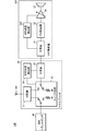
- FIG. 1st Embodiment It is a functional block diagram which shows the structure of the wireless communication apparatus which concerns on 1st Embodiment.
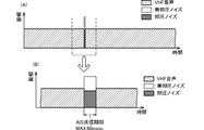
- (A) and (B) are diagrams showing the first aspect of the change of the output sound.
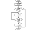
- It is a flowchart which shows one aspect of the communication method of a VHF radio signal.
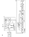
- It is a functional block diagram which shows the structure of the wireless communication apparatus which concerns on 2nd Embodiment.
- It is a flowchart which shows one aspect of the communication method of a VHF radio signal.
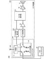
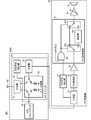
- FIG. 1 is a functional block diagram showing a configuration of a wireless communication device according to the first embodiment.
- the wireless communication device 10 includes an antenna 100, a VHF splitter 20, a VHF radio 30, and an AIS transponder 40.
- the VHF splitter 20 corresponds to the "splitter” of the present invention.
- the VHF radio 30 corresponds to the "FM communication device” or “FM communication unit” of the present invention.
- the AIS transponder 40 corresponds to the "TDMA communication unit” of the present invention.
- the antenna 100 is connected to the VHF splitter 20.
- the VHF splitter 20 connects to the VHF radio 30 and the AIS transponder 40.
- the antenna 100 transmits and receives VHF radio signals and AIS signals.
- the frequency band of the VHF radio signal and the frequency band of the AIS signal overlap.
- the AIS transponder 40 transmits and receives AIS signals by the TDMA method.
- the VHF splitter 20 includes a distributor 21, a switch circuit 22, a demultiplexer 23, and a switching state detection unit 24.
- the distributor 21 is connected to the antenna 100 and the switch circuit 22.
- the switch circuit 22 is connected to the duplexer 23 and the AIS transponder 40.
- the demultiplexer 23 is connected to the VHF radio 30.
- the switching state detection unit 24 is connected to the switch circuit 22 and the demultiplexer 23.
- the distributor 21 outputs a radio signal from the antenna 100 to two terminals in the switch circuit 22. These two terminals are terminals connected to the distributor 21. The distributor 21 outputs a radio signal output from one of these two terminals to the antenna 100. Further, the distributor 21 outputs a radio signal output from the other of these two terminals to the antenna 100.
- the switch circuit 22 cuts off the connection between the distributor 21 and the demultiplexer 23 when transmitting the AIS signal.
- the switch circuit 22 connects the distributor 21 and the demultiplexer 23 at a time other than the time when the AIS signal is transmitted.
- the switch circuit 22 cuts off the connection between the distributor 21 and the AIS transponder 40 when transmitting the VHF signal.
- the switch circuit 22 connects the distributor 21 and the AIS transponder 40 at a time other than the time when the VHF signal is transmitted.
- the VHF splitter 20 connects the AIS transponder 40 and the antenna 100 when transmitting an AIS signal. Further, when transmitting the AIS signal, the VHF splitter 20 cuts off the connection between the VHF radio 30 and the antenna 100.
- the VHF splitter 20 when transmitting the VHF signal, the VHF splitter 20 cuts off the connection between the AIS transponder 40 and the antenna 100. Further, when transmitting a VHF signal, the VHF splitter 20 connects the VHF radio 30 and the antenna 100. The VHF splitter 20 connects both the VHF radio 30 and the AIS transponder 40 to the antenna 100 when neither the AIS signal is transmitted nor the VHF signal is transmitted.
- the switching state detection unit 24 detects the switching state of the switch circuit 22 and outputs the switching state detection signal to the duplexer 23.
- the switching state detection unit 24 outputs a switching state detection signal if the demultiplexer 23 (VHF radio 30) and the distributor 21 (antenna 100) are not connected. If the demultiplexer 23 (VHF radio 30) and the distributor 21 (antenna 100) are connected, the switching state detection unit 24 stops the output of the switching state detection signal.
- the switching state detection signal is, for example, a DC voltage signal having a predetermined level (non-zero).
- the switching state detection signal has a frequency different from that of the VHF radio signal, and is not limited to a DC voltage signal as long as it can be demultiplexed with respect to the VHF radio signal.
- the demultiplexer 23 combines the signal from the switch circuit 22 side and the signal from the switching state detection unit 24 and outputs the signal to the VHF radio 30. As a result, the demultiplexer 23 outputs the VHF radio signal to the VHF radio 30 at a time other than the time when the AIS signal is transmitted. When transmitting the AIS signal, the demultiplexer 23 outputs the switching state detection signal to the VHF radio 30.
- the VHF radio 30 includes a demultiplexer 31, an FM demodulation unit 32, an amplifier 33, an AIS transmission detection unit 34, an output sound control unit 35, a variable amplifier 36, and a speaker 37.
- the AIS transmission detection unit 34 corresponds to the "TDMA transmission detection unit" of the present invention.
- FIG. 1 shows only the reception function of the VHF radio signal in the VHF radio 30, the VHF radio 30 may have a transmission function unit of the VHF radio signal.
- the demultiplexer 31 is connected to the demultiplexer 23 of the VHF splitter 20.
- the demultiplexer 31 is connected to the FM demodulation unit 32 and the AIS transmission detection unit 34.
- the FM demodulation unit 32 is connected to the input end of the amplifier 33.
- the output end of the amplifier 33 is connected to the output sound control unit 35.
- the AIS transmission detection unit 34 is connected to the output sound control unit 35.
- the output sound control unit 35 is connected to the input terminal of the variable amplifier 36.
- the output end of the variable amplifier 36 is connected to the speaker 37.
- the demultiplexer 31 has a filter function.
- the demultiplexer 31 outputs the VHF radio signal to the FM demodulation unit 32 and does not output it to the AIS transmission detection unit 34.
- the demultiplexer 31 outputs the switching state detection signal to the AIS transmission detection unit 34, and does not output the switching state detection signal to the FM demodulation unit 32.
- the FM demodulation unit 32 demodulates the VHF radio signal and outputs it to the amplifier 33.
- the amplifier 33 amplifies the demodulated signal and outputs it to the output sound control unit 35.
- the AIS transmission detection unit 34 detects the switching state detection signal, it generates an on signal and outputs it to the output sound control unit 35.
- the AIS transmission detection unit 34 does not output an on signal unless it detects a switching state detection signal.
- the on signal is, for example, a DC voltage signal of a predetermined level, and is a signal exceeding the on level of the AND gate 351 described later.
- the output sound control unit 35 includes an AND gate 351, a switch element 352, a switch element 353, and an attenuator 354.
- An ENABLE signal is input to the first input terminal of the AND gate 351.
- the second input terminal of the AND gate 351 is connected to the AIS transmission detection unit 34.
- the output terminal of the AND gate 351 is connected to the switch element 352 and the switch element 353.
- the switch element 352 includes a common terminal, a first selection terminal, and a second selection terminal. The switch element 352 selects either the first selection terminal or the second selection terminal and connects to the common terminal.
- the switch element 353 includes a common terminal, a third selection terminal, and a fourth selection terminal.
- the switch element 353 selects either the third selection terminal or the fourth selection terminal and connects to the common terminal.
- the common terminal of the switch element 352 is connected to the output end of the amplifier 33.
- the first selection terminal of the switch element 352 is connected to the third selection terminal of the switch element 353.
- the second selection terminal of the switch element 352 is connected to the fourth selection terminal of the switch element 353 via the attenuator 354.
- the common terminal of the switch element 353 is connected to the input end of the variable amplifier 36.
- the attenuator 354 is a resistor or the like and suppresses the level of the input signal.
- the AND gate 351 outputs a switch changeover signal when an on signal from the AIS transmission detection unit 34 is input.
- the switch element 352 connects the common terminal and the first selection terminal if the switch changeover signal is not input.
- the switch element 352 connects the common terminal and the second selection terminal if a switch switching signal is input.
- the switch element 353 connects the common terminal and the third selection terminal if the switch changeover signal is not input.
- the switch element 353 connects the common terminal and the fourth selection terminal if a switch switching signal is input.
- the switch element 352 and the switch element 353 are directly connected to each other unless the AIS signal is being transmitted. That is, unless the AIS signal is being transmitted, the output end of the amplifier 33 is connected to the input end of the variable amplifier 36 without going through the attenuator 354.
- the switch element 352 and the switch element 353 are connected via the attenuator 354 if the AIS signal is being transmitted. That is, if the AIS signal is being transmitted, the output end of the amplifier 33 is connected to the input end of the variable amplifier 36 via the attenuator 354.
- the variable amplifier 36 amplifies the input signal according to the set gain and outputs it to the speaker 37.
- the speaker 37 converts the output signal of the variable amplifier 36 into sound and emits the sound.
- the VHF radio 30 can realize the following effects.
- the output sound control unit 35 outputs the VHF radio signal without being suppressed by the attenuator 354 unless the AIS signal is being transmitted. On the other hand, if the AIS signal is being transmitted, the output sound control unit 35 suppresses the noise generated by the FM demodulation unit 32 with the attenuator 354 and outputs the noise.
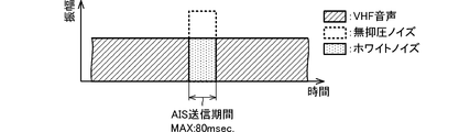
- FIGS. 2 (A) and 2 (B) are diagrams showing a first aspect of a change in output sound.
- the VHF radio 30 is FM demodulated from the VHF radio signal during the period during which the AIS signal is not being transmitted (the AIS transmission period in FIG. 2 (B)). Outputs audio at a predetermined level (amplitude). Further, during the transmission of the AIS signal, the VHF radio 30 suppresses and outputs the noise generated by the FM demodulation unit 32. As shown in FIGS. 2 (A) and 2 (B), the noise level (amplitude) is lower than the VHF voice level. On the other hand, in the conventional configuration in which this control is not performed, the noise level is significantly higher than the VHF voice level.
- the VHF radio 30 can suppress the noise generated when the VHF radio communication is interrupted by the transmission of the AIS signal.
- the AIS signal is inserted in a time extremely shorter than the time during which the VHF sound is emitted.
- the maximum transmission period of the AIS signal is 80 msec. Is.
- the noise interrupted by the VHF voice is jarring.
- the VHF radio 30 can suppress this jarring noise and can comfortably make a call or the like by VHF voice.
- each process realized by the VHF radio 30 is realized by a separate functional unit.
- each of the above-mentioned processes may be programmed and stored, and the arithmetic processing unit may execute this program.
- the arithmetic processing unit may execute the flowchart shown in FIG.
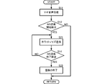
- FIG. 3 is a flowchart showing an aspect of a VHF radio signal communication method. Note that FIG. 3 shows the start state in which the VHF radio signal is being received.
- the arithmetic processing unit receives the VHF radio signal (S11). When the arithmetic processing unit detects the start of transmission of the AIS signal (S12: YES), the arithmetic processing unit suppresses the level of the output sound (S13). The arithmetic processing unit does not suppress the output sound level unless it has detected the start of transmission of the AIS signal (S12: NO).
- the arithmetic processing unit When the arithmetic processing unit detects the end of transmission of the AIS signal while suppressing the level (S14: YES), it restores the output sound level (S15). Restoring the output sound level is to stop suppressing the output sound level. If the arithmetic processing unit does not detect the end of transmission of the AIS signal (S14: NO), the arithmetic processing unit continues to suppress the output sound level.
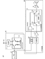
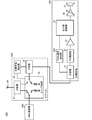
- FIG. 4 is a functional block diagram showing the configuration of the wireless communication device according to the second embodiment.
- the wireless communication device 10A according to the second embodiment is different from the wireless communication device 10 according to the first embodiment in the configuration of the VHF radio 30A.
- the basic configuration of the wireless communication device 10A is the same as that of the wireless communication device 10, and the description of the same parts will be omitted.
- the VHF radio 30A includes a VHF splitter 20A, an FM demodulation unit 32, an amplifier 33, an AIS transmission detection unit 34A, an output sound control unit 35, a variable amplifier 36, and a speaker 37. That is, the VHF radio 30A includes the configuration of the VHF radio 30 and the configuration of the VHF splitter 20 shown in the first embodiment in one housing.
- the AIS transmission detection unit 34A is connected to the switch circuit 22.
- the AIS transmission detection unit 34A realizes the functions of the switching state detection unit 24 and the AIS transmission detection unit 34 shown in the first embodiment. More specifically, for example, the AIS transmission detection unit 34A generates an on signal and outputs it to the output sound control unit 35 if the FM demodulation unit 32 and the distributor 21 (antenna 100) are not connected. The AIS transmission detection unit 34A does not output an on signal if the FM demodulation unit 32 and the distributor 21 (antenna 100) are connected.
- the VHF radio 30A has the same effect as the VHF radio 30 shown in the first embodiment. Then, the wireless communication device 10A can reduce the number of components as compared with the wireless communication device 10 according to the first embodiment.
- FIG. 5 is a functional block diagram showing a configuration of a wireless communication device according to a third embodiment.
- the wireless communication device 10B according to the third embodiment is different from the wireless communication device 10 according to the first embodiment in the configuration of the VHF radio 30B.
- the other configuration of the wireless communication device 10B is the same as that of the wireless communication device 10, and the description of the same parts will be omitted.
- the VHF radio 30B includes a demultiplexer 31, an AIS transmission detection unit 34, a variable amplifier 36, a speaker 37, a DSP325, an AD conversion unit 381, and a DA conversion unit 382.
- the demultiplexer 31 is connected to the demultiplexer 23 of the VHF splitter 20.
- the demultiplexer 31 is connected to the AIS transmission detection unit 34 and the AD conversion unit 381.
- the AD conversion unit 381 and the AIS transmission detection unit 34 are connected to the DSP 325.
- the DSP325 is a programmable signal processing circuit.
- the DSP 325 includes an FM demodulation unit 32B and an output sound control unit 35B.
- the FM demodulation unit 32B is connected to the AD conversion unit 381.
- the FM demodulation unit 32B is connected to the output sound control unit 35B.
- the output sound control unit 35B is connected to the DA conversion unit 382.
- the DA conversion unit 382 is connected to the input end of the variable amplifier 36.
- the output end of the variable amplifier 36 outputs to the speaker 37.
- the AD conversion unit 381 converts a VHF radio signal composed of an analog signal into a digital signal and outputs it to the FM demodulation unit 32B.
- the FM demodulation unit 32B demodulates the VHF radio signal and outputs it to the output sound control unit 35B.
- the output sound control unit 35B amplifies and outputs the VHF radio signal if it has not received the on signal from the AIS transmission detection unit 34. That is, the output sound control unit 35B amplifies and outputs the VHF radio signal during the period other than the transmission of the AIS signal.
- the output sound control unit 35B receives an on-signal from the AIS transmission detection unit 34, the output sound control unit 35B suppresses the noise level output from the FM demodulation unit 32B and outputs the sound.
- the output sound control unit 35B can replace the noise output from the FM demodulation unit 32B with white noise and output the noise.
- the level (amplitude) of the white noise is preferably about the same as the amplitude of the VHF radio signal.
- other audio signals or the like may be used.
- the other audio signal for example, a pseudo audio signal obtained by filtering white noise, a copy signal of the audio signal immediately before switching, or the like can be adopted.
- the output sound control unit 35B suppresses the noise of FM demodulation and outputs it, or outputs white noise during the transmission of the AIS signal.
- the DA conversion unit 382 converts the output signal of the output sound control unit 35B composed of a digital signal into an analog signal and outputs it to the variable amplifier 36.
- the VHF radio 30B has the same effect as the VHF radio 30.
- the VHF radio 30B has the same effect as the VHF radio 30 by outputting white noise that is less likely to be offensive to the ears instead of the noise of FM demodulation.
- FIG. 6 is a diagram showing a second mode of change in output sound.
- the VHF radio 30B outputs the VHF radio FM demodulated from the VHF radio signal at a predetermined level (amplitude) during a period during which the AIS signal is not being transmitted (AIS transmission period in FIG. 6). Further, during the transmission of the AIS signal, the VHF radio 30B outputs white noise instead of the noise generated by the FM demodulation unit 32. As shown in FIG. 6, the level (amplitude) of white noise is substantially the same as the level of VHF voice.
- the output sound control unit 35B can execute delay processing.
- the output sound control unit 35B can guarantee the delay of the start timing of suppression with respect to the noise of FM demodulation. Therefore, the output sound control unit 35B can more reliably output the noise whose level is suppressed.
- the output sound control unit 35B can guarantee a delay in the start timing of switching to white noise with respect to the noise of FM demodulation. Therefore, the output sound control unit 35B can more reliably output white noise instead of FM demodulation noise.
- each process realized by the VHF radio 30B is realized by a separate functional unit.
- each of the above-mentioned processes may be programmed and stored, and the arithmetic processing unit may execute this program.
- the arithmetic processing unit may execute the flowchart shown in FIG.
- FIG. 7 is a flowchart showing one aspect of the communication method of the VHF radio signal. Note that FIG. 7 shows a start state in which a VHF radio signal is being received. Further, FIG. 7 shows an embodiment in which FM demodulation noise is replaced with white noise.
- the arithmetic processing unit receives the VHF radio signal (S11). When the arithmetic processing unit detects the start of transmission of the AIS signal (S12: YES), it replaces it with white noise (S21). If the arithmetic processing unit has not detected the start of transmission of the AIS signal (S12: NO), the arithmetic processing unit does not replace the white noise.
- the arithmetic processing device When the arithmetic processing device detects the end of transmission of the AIS signal during the replacement with white noise (S14: YES), the arithmetic processing device ends the replacement with white noise (S22). If the arithmetic processing unit does not detect the end of transmission of the AIS signal (S14: NO), the arithmetic processing unit continues the replacement with white noise.
- FIG. 8 is a functional block diagram showing a configuration of a wireless communication device according to a fourth embodiment.
- the wireless communication device 10C according to the fourth embodiment is different from the wireless communication device 10 according to the first embodiment in that it has an AIS communication device 400.
- the basic configuration of the wireless communication device 10C is the same as that of the wireless communication device 10, and the description of the same parts will be omitted.
- the AIS communication device 400 includes an AIS transponder 40 and a VHF splitter 20. That is, the AIS communication device 400 includes the configuration of the AIS transponder 40 and the VHF splitter 20 shown in the first embodiment in one housing.
- the wireless communication device 10C has the same effect as the wireless communication device 10 shown in the first embodiment. Then, the wireless communication device 10C can reduce the number of components as compared with the wireless communication device 10 according to the first embodiment.
- FIG. 9 is a functional block diagram showing the configuration of the wireless communication device according to the fifth embodiment.
- the wireless communication device 10D according to the fifth embodiment differs from the wireless communication device 10C according to the fourth embodiment in the connection mode of the switching state detection unit 24.
- Other configurations of the wireless communication device 10D are the same as those of the wireless communication device 10, and the description of the same parts will be omitted.
- the switching state detection unit 24 When the switching state detection unit 24 detects the AIS transmission signal from the AIS transponder 40, it outputs the switching state detection signal to the duplexer 23. For example, when the switching state detection unit 24 detects that the signal level output from the AIS transponder 40 is equal to or higher than a predetermined level, it detects that the AIS transmission signal is being transmitted. The switching state detection unit 24 does not output the switching state detection signal to the demultiplexer 23 unless the AIS transmission signal is detected from the AIS transponder 40.
- the wireless communication device 10D has the same effect as the wireless communication device 10C.
- FIG. 10 is a functional block diagram showing a configuration of a wireless communication device according to a sixth embodiment.
- the wireless communication device 10E according to the sixth embodiment has the ON signal of the VHF splitter 20E and the AIS transmission detection unit 34E with respect to the wireless communication device 10 according to the first embodiment. It differs in the generation method.
- Other configurations of the wireless communication device 10E are the same as those of the wireless communication device 10, and the description of the same parts will be omitted.
- the VHF splitter 20E includes a distributor 21 and a switch circuit 22.
- the switch circuit 22 is connected to the distributor 21, the AIS transponder 40, and the FM demodulation unit 32 of the VHF radio 30C. That is, the VHF splitter 20E has a configuration in which the demultiplexer 23 and the switching state detection unit 24 are omitted from the VHF splitter 20 according to the first embodiment.
- the VHF radio 30E has a configuration in which the demultiplexer 31 is omitted from the VHF radio 30 according to the first embodiment.
- the AIS transmission detection unit 34E is connected to the AIS transponder 40.
- the AIS transmission detection unit 34E When the AIS transmission signal is input from the AIS transponder 40, the AIS transmission detection unit 34E generates an on signal and outputs it to the output sound control unit 35. For example, when the AIS transmission detection unit 34E detects that the level of the input signal is equal to or higher than a predetermined level, it determines that the AIS transmission signal has been input. The AIS transmission detection unit 34E does not generate an on signal unless an AIS communication signal (transmission signal) is input from the AIS transponder 40.
- the wireless communication device 10E has the same effect as that of the wireless communication device 10.
- FIG. 11 is a functional block diagram showing the configuration of the wireless communication device according to the seventh embodiment.
- the wireless communication device 10F according to the seventh embodiment is different from the wireless communication device 10 according to the first embodiment in that a VHF radio 30F is provided.
- Other configurations of the wireless communication device 10F are the same as those of the wireless communication device 10, and the description of the same parts will be omitted.
- the VHF radio 30F includes a demultiplexer 31, an FM demodulation unit 32, an AIS transmission detection unit 34F, a variable amplifier 36, and a speaker 37.
- the FM demodulation unit 32 is connected to the input end of the variable amplifier 36.
- the AIS transmission detection unit 34F detects the switching state detection signal, it generates an on signal and outputs it to the variable amplifier 36.
- the on signal is a signal that reduces the gain of the variable amplifier 36.
- the AIS transmission detection unit 34F does not generate an on signal unless the switching state detection signal is detected. As a result, the gain of the variable amplifier 36 does not decrease.
- the VHF radio 30F suppresses FM demodulation noise during AIS transmission and outputs it, and outputs VHF audio at a predetermined level during a period other than AIS transmission. That is, the VHF radio 30F has the same effect as the VHF radio 30 shown in the first embodiment.
- FIG. 12 is a functional block diagram showing the configuration of the wireless communication device according to the eighth embodiment.
- Each of the above embodiments shows a wireless communication device that communicates an AIS signal and a VHF radio signal.
- the AIS signal may be another TDMA signal and the VHF radio signal may be an FM communication signal in another frequency band.
- the frequency band of the TDMA signal and the frequency band of the VHF radio signal overlap.
- the basic configuration and processing of the wireless communication device 10G according to the eighth embodiment are the same as those of the wireless communication device 10 according to the first embodiment, and the description of the same parts will be omitted.
- the wireless communication device 10G includes an antenna 100, a splitter 20G, an FM radio device 30G, and a TDMA communication device 40G.
- the splitter 20G includes a distributor 21, a switch circuit 22, a demultiplexer 23, and a switching state detection unit 24.
- the FM radio 30G includes a demultiplexer 31, an FM demodulation unit 32, an amplifier 33, a TDMA communication detection unit 34G, an output sound control unit 35, a variable amplifier 36, and a speaker 37.
- the TDMA communication device 40G performs the same processing as the AIS transponder 40 according to the first embodiment on the TDMA communication signal.
- the TDMA communication detection unit 34G performs the same processing as the AIS transmission detection unit 34 according to the first embodiment.
- the noise at the time of FM demodulation can be suppressed by providing the configuration of the wireless communication device 10G.
- All processes described herein can be embodied and fully automated by software code modules executed by a computing system that includes one or more computers or processors.
- the code module can be stored on any type of non-transitory computer-readable medium or other computer storage device. Some or all of the methods may be embodied in dedicated computer hardware.
- any particular action, event, or function of any of the algorithms described herein may be performed in different sequences and may be added, merged, or excluded altogether. (For example, not all described acts or events are required to execute an algorithm). Further, in certain embodiments, operations or events are performed in parallel rather than sequentially, for example through multithreading, interrupt handling, or through multiple processors or processor cores, or on other parallel architectures. Can be done. In addition, different tasks or processes can be performed by different machines and / or computing systems that can work together.
- the various exemplary logic blocks and modules described in connection with the embodiments disclosed herein can be implemented or executed by a machine such as a processor.
- the processor may be a microprocessor, but instead, the processor may be a controller, a microcontroller, or a state machine, or a combination thereof.
- the processor can include electrical circuitry configured to process computer-executable instructions.
- the processor comprises an application specific integrated circuit (ASIC), field programmable gate array (FPGA), or other programmable device that performs logical operations without processing computer-executable instructions.
- ASIC application specific integrated circuit
- FPGA field programmable gate array
- a processor may also be a combination of computing devices, such as a combination of digital signal processors (digital signal processors) and microprocessors, multiple microprocessors, one or more microprocessors in combination with DSP cores, or any other thereof. It can be implemented as such a configuration. Although described primarily with respect to digital technology herein, the processor may also include primarily analog elements. For example, some or all of the signal processing algorithms described herein can be implemented by analog circuits or mixed analog and digital circuits. Computing environments include, but are not limited to, any type of computer system that is based on a microprocessor, mainframe computer, digital signal processor, portable computing device, device controller, or computing engine within the device. be able to.
- conditional languages such as “can,” “can,” “will,” or “possibly” have certain embodiments that include certain features, elements, and / or steps, but other. Embodiments are understood in the context commonly used to convey that they do not include. Thus, such conditional languages are generally any method in which features, elements and / or steps are required for one or more embodiments, or one or more embodiments are these features. It does not mean that the elements and / or steps are included in any particular embodiment or necessarily include logic for determining whether they are performed.
- a disjunctive language such as the phrase "at least one of X, Y, and Z" is an item, term, etc., any of X, Y, Z, or any combination thereof, unless otherwise specified. Understood in the context commonly used to indicate that it can be (eg X, Y, Z). Thus, such a disjunctive language generally requires at least one of X, at least one of Y, or at least one of Z, each of which has a particular embodiment. Does not mean.
- Numerals such as “one” should generally be construed to include one or more described items unless specifically stated otherwise.
- terms such as “one device configured to” are intended to include one or more listed devices.
- One or more of such enumerated devices can also be collectively configured to perform the described citations.
- a processor configured to perform A, B, and C below refers to a first processor configured to perform A and a second processor configured to perform B and C.
- a specific number enumeration of the introduced examples is explicitly enumerated, those skilled in the art will appreciate that such enumeration is typically at least the enumerated number (eg, other modifiers).
- a mere enumeration of "two enumerations” without the use should be interpreted to mean at least two enumerations, or two or more enumerations).
- the term “horizontal” as used herein, regardless of its orientation, is a plane parallel to the plane or surface of the floor of the area in which the described system is used, or description. Is defined as the plane in which the method is performed.
- the term “floor” can be replaced with the terms “ground” or “water surface”.
- the term “vertical / vertical” refers to the direction perpendicular / vertical to the defined horizon. Terms such as “upper”, “lower”, “lower”, “upper”, “side”, “higher”, “lower”, “upper”, “beyond”, and “lower” are defined for the horizontal plane. ing.
- connection/coupling includes direct connection and/or connection having an intermediate structure between the two described components.
- the numbers preceded by terms such as “approximately,” “about,” and “substantially” as used herein include the enumerated numbers, and further. Represents an amount near the stated amount that performs a desired function or achieves a desired result. For example, “approximately,” “about,” and “substantially” mean values less than 10% of the stated values, unless otherwise stated.
- the features of the embodiments in which terms such as “approximately,” “about,” and “substantially” are previously disclosed perform further desired functions. Or represent a feature that has some variability to achieve the desired result for that feature.
Landscapes
- Engineering & Computer Science (AREA)
- Computer Networks & Wireless Communication (AREA)
- Signal Processing (AREA)
- Transceivers (AREA)
- Noise Elimination (AREA)
Abstract
【課題】TDMA方式の送信時にFM復調に生じるノイズを抑制する。 【解決手段】FM通信装置は、FM復調部32、TDMA送信検出部34F、および、出力音制御部35を備える。FM復調部32は、周波数帯域が重なるTDMA信号とFM通信信号とを受信可能なアンテナで受信されたFM通信信号を復調する。TDMA送信検出部34Fは、TDMA信号の送信中を検出する。出力音制御部35は、TDMA送信検出部34Fの検出結果を用いて、TDMA信号の送信中に、FM復調部32からの出力音を制御する。
Description
本発明は、AIS等のTDMA通信とVHF通信等のFM通信とをこれらに共通のアンテナで実現する無線通信装置、および、無線通信装置を構成し、FM通信を行うFM通信装置に関する。
特許文献1には、無線通信装置が記載されている。特許文献1に記載の無線通信装置は、VHF通信とAIS通信とを行っている。VHF通信の周波数帯域とAIS通信の周波数帯域とは重なっている。したがって、VHF通信とAIS通信とは、1個のアンテナによって行われている。
VHF受信部とAIS通信部とは、スプリッタを介して、アンテナに接続している。スプリッタは、VHF無線信号を受信する時には、VHF受信部とアンテナとを接続する。スプリッタは、AIS通信を行う時には、AIS通信部とアンテナとを接続する。
AIS通信は、TDMA(Time Division Multiple Access)方式を採用している。このため、AIS通信部は、送信時刻になると、AIS信号を送信する。AIS信号の送信中、VHF受信部とアンテナとの接続は切断される。すなわち、特許文献1に記載示すような従来の無線通信装置は、AIS通信時に、VHF受信部に無線信号を出力しない。
しかしながら、VHF受信部は、FM復調方式を用いているので、無線信号が入力されず、入力信号のレベルが急激に低下すると、ノイズを発生してしまう。
したがって、本発明の目的は、TDMA方式の送信時にFM復調に生じるノイズを抑制する技術を提供することにある。
この発明のFM通信装置は、FM復調部、TDMA送信検出部、および、出力音制御部を備える。FM復調部は、周波数帯域が重なるTDMA信号とFM通信信号とを受信可能なアンテナで受信されたFM通信信号を復調する。TDMA送信検出部は、TDMA信号の送信中を検出する。出力音制御部は、TDMA送信検出部の検出結果を用いて、TDMA信号の送信中に、FM復調部からの出力音を制御する。
この構成では、TDMA信号の送信中にFM復調において発生するノイズの出力は、制御される。
この発明によれば、TDMA方式の送信時にFM復調に生じるノイズを抑制できる。特に、VHF無線の受信中に極短時間のAIS通信の送信が割り込む際のノイズを抑制できる。
(第1実施形態)
本発明の第1の実施形態に係る無線通信装置について、図を参照して説明する。図1は、第1の実施形態に係る無線通信装置の構成を示す機能ブロック図である。
本発明の第1の実施形態に係る無線通信装置について、図を参照して説明する。図1は、第1の実施形態に係る無線通信装置の構成を示す機能ブロック図である。
図1に示すように、無線通信装置10は、アンテナ100、VHFスプリッタ20、VHF無線機30、および、AISトランスポンダ40を備える。VHFスプリッタ20は、本発明の「スプリッタ」に対応する。VHF無線機30は、本発明の「FM通信装置」または「FM通信部」に対応する。AISトランスポンダ40は、本発明の「TDMA通信部」に対応する。
アンテナ100は、VHFスプリッタ20に接続する。VHFスプリッタ20は、VHF無線機30およびAISトランスポンダ40に接続する。
アンテナ100は、VHF無線信号およびAIS信号を送受信する。VHF無線信号の周波数帯域とAIS信号の周波数帯域とは重なる。
AISトランスポンダ40は、TDMA方式で、AIS信号の送受信を行う。
(VHFスプリッタ20の構成および信号処理)
VHFスプリッタ20は、分配器21、スイッチ回路22、分波器23、および、切替状態検出部24を備える。分配器21は、アンテナ100およびスイッチ回路22に接続する。スイッチ回路22は、分波器23およびAISトランスポンダ40に接続する。分波器23は、VHF無線機30に接続する。切替状態検出部24は、スイッチ回路22および分波器23に接続する。
VHFスプリッタ20は、分配器21、スイッチ回路22、分波器23、および、切替状態検出部24を備える。分配器21は、アンテナ100およびスイッチ回路22に接続する。スイッチ回路22は、分波器23およびAISトランスポンダ40に接続する。分波器23は、VHF無線機30に接続する。切替状態検出部24は、スイッチ回路22および分波器23に接続する。
分配器21は、アンテナ100からの無線信号を、スイッチ回路22における2端子に出力する。この2端子は、分配器21に接続する端子である。分配器21は、これら2端子の一方から出力された無線信号を、アンテナ100に出力する。また、分配器21は、これら2端子の他方から出力された無線信号を、アンテナ100に出力する。
スイッチ回路22は、AIS信号の送信時には、分配器21と分波器23との接続を遮断する。
また、スイッチ回路22は、AIS信号の送信時以外の時間には、分配器21と分波器23とを接続する。
スイッチ回路22は、VHF信号の送信時には、分配器21とAISトランスポンダ40との接続を遮断する。
また、スイッチ回路22は、VHF信号の送信時以外の時間には、分配器21とAISトランスポンダ40とを接続する。
この構成によって、AIS信号の送信時には、VHFスプリッタ20は、AISトランスポンダ40とアンテナ100とを接続する。また、AIS信号の送信時には、VHFスプリッタ20は、VHF無線機30とアンテナ100との接続を遮断する。
一方、VHF信号の送信時には、VHFスプリッタ20は、AISトランスポンダ40とアンテナ100との接続を遮断する。また、VHF信号の送信時には、VHFスプリッタ20は、VHF無線機30とアンテナ100とを接続する。なお、VHFスプリッタ20は、AIS信号の送信、VHF信号の送信のいずれでもないときは、アンテナ100に対して、VHF無線機30とAISトランスポンダ40の両方を接続する。
切替状態検出部24は、スイッチ回路22の切替状態を検出して、切替状態検出信号を分波器23に出力する。切替状態検出部24は、分波器23(VHF無線機30)と分配器21(アンテナ100)が接続していなければ、切替状態検出信号を出力する。切替状態検出部24は、分波器23(VHF無線機30)と分配器21(アンテナ100)が接続していれば、切替状態検出信号の出力を停止する。切替状態検出信号は、例えば、所定レベル(0でない)からなる直流の電圧信号である。なお、切替状態検出信号は、VHF無線信号と異なる周波数であり、VHF無線信号に対して分波可能であれば、直流の電圧信号に限らない。
分波器23は、スイッチ回路22側からの信号と、切替状態検出部24からの信号とを合波して、VHF無線機30に出力する。これにより、AIS信号の送信時以外の時間では、分波器23は、VHF無線信号を、VHF無線機30に出力する。AIS信号の送信時には、分波器23は、切替状態検出信号を、VHF無線機30に出力する。
(VHF無線機30の構成および信号処理)
VHF無線機30は、分波器31、FM復調部32、アンプ33、AIS送信検出部34、出力音制御部35、可変アンプ36、および、スピーカ37を備える。AIS送信検出部34は、本発明の「TDMA送信検出部」に対応する。なお、図1は、VHF無線機30におけるVHF無線信号の受信機能のみを記載しているが、VHF無線機30は、VHF無線信号の送信機能部を有していてもよい。
VHF無線機30は、分波器31、FM復調部32、アンプ33、AIS送信検出部34、出力音制御部35、可変アンプ36、および、スピーカ37を備える。AIS送信検出部34は、本発明の「TDMA送信検出部」に対応する。なお、図1は、VHF無線機30におけるVHF無線信号の受信機能のみを記載しているが、VHF無線機30は、VHF無線信号の送信機能部を有していてもよい。
分波器31は、VHFスプリッタ20の分波器23に接続する。分波器31は、FM復調部32およびAIS送信検出部34に接続する。FM復調部32は、アンプ33の入力端に接続する。アンプ33の出力端は、出力音制御部35に接続する。AIS送信検出部34は、出力音制御部35に接続する。出力音制御部35は、可変アンプ36の入力端に接続する。可変アンプ36の出力端は、スピーカ37に接続する。
分波器31は、フィルタ機能を有する。分波器31は、VHF無線信号を、FM復調部32に出力し、AIS送信検出部34に出力しない。分波器31は、切替状態検出信号を、AIS送信検出部34に出力し、FM復調部32に出力しない。
FM復調部32は、VHF無線信号を復調して、アンプ33に出力する。アンプ33は、復調信号を増幅して、出力音制御部35に出力する。
AIS送信検出部34は、切替状態検出信号を検出すれば、オン信号を生成して、出力音制御部35に出力する。AIS送信検出部34は、切替状態検出信号を検出しなければ、オン信号を出力しない。オン信号は、例えば、所定レベルの直流の電圧信号であり、後述のANDゲート351のオンレベルを超える信号である。
出力音制御部35は、ANDゲート351、スイッチ素子352、スイッチ素子353、および、減衰器354を備える。ANDゲート351の第1入力端子には、ENABLE信号が入力されている。ANDゲート351の第2入力端子は、AIS送信検出部34に接続する。ANDゲート351の出力端子は、スイッチ素子352およびスイッチ素子353に接続する。
スイッチ素子352は、共通端子、第1選択端子、および、第2選択端子を備える。スイッチ素子352は、第1選択端子と第2選択端子のいずれかを選択して、共通端子に接続する。
スイッチ素子353は、共通端子、第3選択端子、および、第4選択端子を備える。スイッチ素子353は、第3選択端子と第4選択端子のいずれかを選択して、共通端子に接続する。
スイッチ素子352の共通端子は、アンプ33の出力端に接続する。スイッチ素子352の第1選択端子は、スイッチ素子353の第3選択端子に接続する。スイッチ素子352の第2選択端子は、減衰器354を介して、スイッチ素子353の第4選択端子に接続する。スイッチ素子353の共通端子は、可変アンプ36の入力端に接続する。
減衰器354は、抵抗器等であり、入力された信号のレベルを抑圧する。
ANDゲート351は、AIS送信検出部34からのオン信号が入力されると、スイッチ切替信号を出力する。
スイッチ素子352は、スイッチ切替信号が入力されていなければ、共通端子と第1選択端子とを接続する。スイッチ素子352は、スイッチ切替信号が入力されていれば、共通端子と第2選択端子とを接続する。
スイッチ素子353は、スイッチ切替信号が入力されていなければ、共通端子と第3選択端子とを接続する。スイッチ素子353は、スイッチ切替信号が入力されていれば、共通端子と第4選択端子とを接続する。
これにより、スイッチ素子352とスイッチ素子353とは、AIS信号の送信中でなければ、直接接続する。すなわち、AIS信号の送信中でなければ、アンプ33の出力端は、減衰器354を介することなく、可変アンプ36の入力端に接続する。
一方、スイッチ素子352とスイッチ素子353とは、AIS信号の送信中であれば、減衰器354を介して接続する。すなわち、AIS信号の送信中であれば、アンプ33の出力端は、減衰器354を介して、可変アンプ36の入力端に接続する。
可変アンプ36は、設定されたゲインによって、入力信号を増幅して、スピーカ37に出力する。スピーカ37は、可変アンプ36の出力信号を音に変換して、放音する。
このような構成および制御によって、VHF無線機30は、次に示す作用効果を実現できる。
具体的には、上述の構成および制御によって、出力音制御部35は、AIS信号の送信中でなければ、VHF無線信号を減衰器354で抑圧せずに出力する。一方、出力音制御部35は、AIS信号の送信中であれば、FM復調部32で発生したノイズを減衰器354で抑圧して出力する。
これにより、出力音は、図2(A)、図2(B)に示すように変化する。図2(A)、図2(B)は、出力音の変化の第1態様を示す図である。
図2(A)、図2(B)に示すように、AIS信号の送信中(図2(B)におけるAIS送信期間)でない期間、VHF無線機30は、VHF無線信号からFM復調されたVHF音声を所定レベル(振幅)で出力する。また、AIS信号の送信中、VHF無線機30は、FM復調部32で発生したノイズを抑圧して出力する。図2(A)、図2(B)に示すように、ノイズのレベル(振幅)は、VHF音声のレベルよりも低い。一方、この制御を行わない従来の構成では、ノイズのレベルは、VHF音声のレベルよりも大幅に大きくなる。
このように、VHF無線機30は、AIS信号の送信によってVHF無線通信が中断される際に生じるノイズを抑制できる。特に、AIS信号は、VHF音声が放音される時間よりも極短い時間で挿入される。具体的には、AIS信号の送信期間は、最大で80msec.である。VHF音声に割り込まれるノイズは、耳障りである。しかしながら、この構成を備えることによって、VHF無線機30は、この耳障りなノイズを抑制でき、VHF音声による通話等を快適にできる。
(VHF無線信号の通信方法の第1態様)
上述の説明では、VHF無線機30で実現する各処理は、それぞれに個別の機能部によって実現されている。しかしながら、上述の各処理をプログラム化して記憶しておき、演算処理装置は、このプログラムを実行するようにしてもよい。この場合、例えば、演算処理装置は、図3に示すフローチャートを実行すればよい。図3は、VHF無線信号の通信方法の一態様を示すフローチャートである。なお、図3は、VHF無線信号を受信している状態を開始状態としている。
上述の説明では、VHF無線機30で実現する各処理は、それぞれに個別の機能部によって実現されている。しかしながら、上述の各処理をプログラム化して記憶しておき、演算処理装置は、このプログラムを実行するようにしてもよい。この場合、例えば、演算処理装置は、図3に示すフローチャートを実行すればよい。図3は、VHF無線信号の通信方法の一態様を示すフローチャートである。なお、図3は、VHF無線信号を受信している状態を開始状態としている。
演算処理装置は、VHF無線信号を受信している(S11)。演算処理装置は、AIS信号の送信開始を検出すると(S12:YES)、出力音のレベルを抑圧する(S13)。演算処理装置は、AIS信号の送信開始を検出していなければ(S12:NO)、出力音のレベルの抑圧を行わない。
演算処理装置は、レベルの抑圧中に、AIS信号の送信終了を検出すると(S14:YES)、出力音のレベルを復帰する(S15)。出力音のレベルの復帰は、出力音のレベルの抑圧を停止することである。演算処理装置は、AIS信号の送信終了を検出しなければ(S14:NO)、出力音のレベルの抑圧を継続する。
(第2実施形態)
本発明の第2の実施形態に係る無線通信装置について、図を参照して説明する。図4は、第2の実施形態に係る無線通信装置の構成を示す機能ブロック図である。
本発明の第2の実施形態に係る無線通信装置について、図を参照して説明する。図4は、第2の実施形態に係る無線通信装置の構成を示す機能ブロック図である。
図4に示すように、第2の実施形態に係る無線通信装置10Aは、第1の実施形態に係る無線通信装置10に対して、VHF無線機30Aの構成において異なる。無線通信装置10Aの基本的な構成は、無線通信装置10と同様であり、同様の箇所の説明は省略する。
VHF無線機30Aは、VHFスプリッタ20A、FM復調部32、アンプ33、AIS送信検出部34A、出力音制御部35、可変アンプ36、および、スピーカ37を備える。すなわち、VHF無線機30Aは、第1の実施形態に示したVHF無線機30の構成とVHFスプリッタ20の構成とを、1つの筐体に備える。
AIS送信検出部34Aは、スイッチ回路22に接続する。AIS送信検出部34Aは、第1の実施形態に示した切替状態検出部24とAIS送信検出部34との機能を実現する。より具体的には、例えば、AIS送信検出部34Aは、FM復調部32と分配器21(アンテナ100)が接続していなければ、オン信号を生成して、出力音制御部35に出力する。AIS送信検出部34Aは、FM復調部32と分配器21(アンテナ100)が接続していれば、オン信号を出力しない。
このような構成であっても、VHF無線機30Aは、第1の実施形態に示したVHF無線機30と同様の作用効果を奏する。そして、無線通信装置10Aは、第1の実施形態に係る無線通信装置10と比較して、構成要素を少なくできる。
(第3実施形態)
本発明の第3の実施形態に係る無線通信装置について、図を参照して説明する。図5は、第3の実施形態に係る無線通信装置の構成を示す機能ブロック図である。
本発明の第3の実施形態に係る無線通信装置について、図を参照して説明する。図5は、第3の実施形態に係る無線通信装置の構成を示す機能ブロック図である。
図5に示すように、第3の実施形態に係る無線通信装置10Bは、第1の実施形態に係る無線通信装置10に対して、VHF無線機30Bの構成において異なる。無線通信装置10Bの他の構成は、無線通信装置10と同様であり、同様の箇所の説明は省略する。
VHF無線機30Bは、分波器31、AIS送信検出部34、可変アンプ36、スピーカ37、DSP325、AD変換部381、および、DA変換部382を備える。分波器31は、VHFスプリッタ20の分波器23に接続する。分波器31は、AIS送信検出部34およびAD変換部381に接続する。AD変換部381およびAIS送信検出部34は、DSP325に接続する。
DSP325は、プログラマブルな信号処理回路である。DSP325は、FM復調部32B、および、出力音制御部35Bを備える。FM復調部32Bは、AD変換部381に接続する。FM復調部32Bは、出力音制御部35Bに接続する。出力音制御部35Bは、DA変換部382に接続する。DA変換部382は、可変アンプ36の入力端に接続する。可変アンプ36の出力端は、スピーカ37に出力する。
AD変換部381は、アナログ信号からなるVHF無線信号をデジタル信号に変換して、FM復調部32Bに出力する。FM復調部32Bは、VHF無線信号を復調して、出力音制御部35Bに出力する。
出力音制御部35Bは、AIS送信検出部34からオン信号を受けていなければ、VHF無線信号を増幅して出力する。すなわち、出力音制御部35Bは、AIS信号の送信中以外の期間では、VHF無線信号を増幅して出力する。
出力音制御部35Bは、AIS送信検出部34からオン信号を受けていれば、FM復調部32Bから出力されるノイズのレベルを抑圧して出力する。
なお、出力音制御部35Bは、AIS送信検出部34からオン信号を受けていれば、FM復調部32Bから出力されるノイズを、ホワイトノイズに置換して出力することも可能である。この際、ホワイトノイズのレベル(振幅)は、VHF無線信号の振幅と同じ程度であることが好ましい。また、ホワイトノイズに限らず、他の音声信号等を用いてもよい。他の音声信号としては、例えば、ホワイトノイズをフィルタ処理した疑似音声信号、切り替えの直前の音声信号のコピー信号等を採用することもできる。
すなわち、出力音制御部35Bは、AIS信号の送信中には、FM復調のノイズを抑圧して出力するか、ホワイトノイズを出力する。
DA変換部382は、デジタル信号からなる出力音制御部35Bの出力信号をアナログ信号に変換して、可変アンプ36に出力する。
このように、出力音制御部35Bをプログラマブルな信号処理回路で実現しても、VHF無線機30Bは、VHF無線機30と同様の作用効果を奏する。
また、VHF無線機30Bは、FM復調のノイズに代えて、耳障りになり難いホワイトノイズを出力することで、VHF無線機30と同様の作用効果を奏する。
図6は、出力音の変化の第2態様を示す図である。図6に示すように、AIS信号の送信中(図6におけるAIS送信期間)でない期間、VHF無線機30Bは、VHF無線信号からFM復調されたVHF音声を所定レベル(振幅)で出力する。また、AIS信号の送信中、VHF無線機30Bは、FM復調部32で発生したノイズに代えて、ホワイトノイズを出力する。図6に示すように、ホワイトノイズのレベル(振幅)は、VHF音声のレベルと略同じである。
なお、出力音制御部35Bは、遅延処理を実行できる。この遅延処理によって、出力音制御部35Bは、FM復調のノイズに対する抑圧の開始タイミングの遅延を保証できる。したがって、出力音制御部35Bは、より確実にレベルが抑圧されたノイズを出力できる。もしくは、この遅延処理によって、出力音制御部35Bは、FM復調のノイズに対するホワイトノイズへの切り替えの開始タイミングの遅延を保証できる。したがって、出力音制御部35Bは、FM復調のノイズに代えて、より確実にホワイトノイズを出力できる。
(VHF無線信号の通信方法の第2態様)
上述の説明では、VHF無線機30Bで実現する各処理は、それぞれに個別の機能部によって実現されている。しかしながら、上述の各処理をプログラム化して記憶しておき、演算処理装置は、このプログラムを実行するようにしてもよい。この場合、例えば、演算処理装置は、図7に示すフローチャートを実行すればよい。図7は、VHF無線信号の通信方法の一態様を示すフローチャートである。なお、図7は、VHF無線信号を受信している状態を開始状態としている。また、図7は、FM復調のノイズをホワイトノイズに置換する態様を示す。
上述の説明では、VHF無線機30Bで実現する各処理は、それぞれに個別の機能部によって実現されている。しかしながら、上述の各処理をプログラム化して記憶しておき、演算処理装置は、このプログラムを実行するようにしてもよい。この場合、例えば、演算処理装置は、図7に示すフローチャートを実行すればよい。図7は、VHF無線信号の通信方法の一態様を示すフローチャートである。なお、図7は、VHF無線信号を受信している状態を開始状態としている。また、図7は、FM復調のノイズをホワイトノイズに置換する態様を示す。
演算処理装置は、VHF無線信号を受信している(S11)。演算処理装置は、AIS信号の送信開始を検出すると(S12:YES)、ホワイトノイズに置換する(S21)。演算処理装置は、AIS信号の送信開始を検出していなければ(S12:NO)、ホワイトノイズへの置換を行わない。
演算処理装置は、ホワイトノイズへの置換中に、AIS信号の送信終了を検出すると(S14:YES)、ホワイトノイズへの置換を終了する(S22)。演算処理装置は、AIS信号の送信終了を検出しなければ(S14:NO)、ホワイトノイズへの置換を継続する。
(第4実施形態)
本発明の第4の実施形態に係る無線通信装置について、図を参照して説明する。図8は、第4の実施形態に係る無線通信装置の構成を示す機能ブロック図である。
本発明の第4の実施形態に係る無線通信装置について、図を参照して説明する。図8は、第4の実施形態に係る無線通信装置の構成を示す機能ブロック図である。
図8に示すように、第4の実施形態に係る無線通信装置10Cは、第1の実施形態に係る無線通信装置10に対して、AIS通信装置400を有する点で異なる。無線通信装置10Cの基本的な構成は、無線通信装置10と同様であり、同様の箇所の説明は省略する。
AIS通信装置400は、AISトランスポンダ40とVHFスプリッタ20とを備える。すなわち、AIS通信装置400は、第1の実施形態に示したAISトランスポンダ40とVHFスプリッタ20の構成とを、1つの筐体に備える。
このような構成であっても、無線通信装置10Cは、第1の実施形態に示した無線通信装置10と同様の作用効果を奏する。そして、無線通信装置10Cは、第1の実施形態に係る無線通信装置10と比較して、構成要素を少なくできる。
(第5実施形態)
本発明の第5の実施形態に係る無線通信装置について、図を参照して説明する。図9は、第5の実施形態に係る無線通信装置の構成を示す機能ブロック図である。
本発明の第5の実施形態に係る無線通信装置について、図を参照して説明する。図9は、第5の実施形態に係る無線通信装置の構成を示す機能ブロック図である。
図9に示すように、第5の実施形態に係る無線通信装置10Dは、第4の実施形態に係る無線通信装置10Cに対して、切替状態検出部24の接続態様において異なる。無線通信装置10Dの他の構成は、無線通信装置10と同様であり、同様の箇所の説明は省略する。
切替状態検出部24は、AISトランスポンダ40からAIS送信信号を検出すると、切替状態検出信号を分波器23に出力する。例えば、切替状態検出部24は、AISトランスポンダ40から出力される信号レベルが所定レベル以上であることを検出すると、AIS送信信号の送信中であると検出する。切替状態検出部24は、AISトランスポンダ40からAIS送信信号を検出しないと、切替状態検出信号を分波器23に出力しない。
このような構成であっても、無線通信装置10Dは、無線通信装置10Cと同様の作用効果を奏する。
(第6実施形態)
本発明の第6の実施形態に係る無線通信装置について、図を参照して説明する。図10は、第6の実施形態に係る無線通信装置の構成を示す機能ブロック図である。
本発明の第6の実施形態に係る無線通信装置について、図を参照して説明する。図10は、第6の実施形態に係る無線通信装置の構成を示す機能ブロック図である。
図10に示すように、第6の実施形態に係る無線通信装置10Eは、第1の実施形態に係る無線通信装置10に対して、VHFスプリッタ20E、および、AIS送信検出部34Eにおけるオン信号の生成方法において異なる。無線通信装置10Eの他の構成は、無線通信装置10と同様であり、同様の箇所の説明は省略する。
VHFスプリッタ20Eは、分配器21およびスイッチ回路22を備える。スイッチ回路22は、分配器21、AISトランスポンダ40、および、VHF無線機30CのFM復調部32に接続する。すなわち、VHFスプリッタ20Eは、第1の実施形態に係るVHFスプリッタ20から分波器23および切替状態検出部24を省略した構成を備える。
VHF無線機30Eは、第1の実施形態に係るVHF無線機30に対して、分波器31を省略した構成を備える。AIS送信検出部34Eは、AISトランスポンダ40に接続する。
AIS送信検出部34Eは、AISトランスポンダ40からAIS送信信号が入力されるとオン信号を生成し、出力音制御部35に出力する。例えば、AIS送信検出部34Eは、入力信号のレベルが所定レベル以上であることを検出すると、AIS送信信号が入力されたと判定する。AIS送信検出部34Eは、AISトランスポンダ40からAIS通信信号(送信信号)が入力されなければオン信号を生成しない。
このような構成であっても、無線通信装置10Eは、無線通信装置10と同様の作用効果を奏する。
(第7実施形態)
本発明の第7の実施形態に係る無線通信装置について、図を参照して説明する。図11は、第7の実施形態に係る無線通信装置の構成を示す機能ブロック図である。
本発明の第7の実施形態に係る無線通信装置について、図を参照して説明する。図11は、第7の実施形態に係る無線通信装置の構成を示す機能ブロック図である。
図11に示すように、第7の実施形態に係る無線通信装置10Fは、第1の実施形態に係る無線通信装置10に対して、VHF無線機30Fを備える点で異なる。無線通信装置10Fの他の構成は、無線通信装置10と同様であり、同様の箇所の説明は省略する。
VHF無線機30Fは、分波器31、FM復調部32、AIS送信検出部34F、可変アンプ36、および、スピーカ37を備える。FM復調部32は、可変アンプ36の入力端に接続する。
AIS送信検出部34Fは、切替状態検出信号を検出すれば、オン信号を生成して可変アンプ36に出力する。オン信号は、可変アンプ36の利得を低下させる信号である。AIS送信検出部34Fは、切替状態検出信号を検出しなければ、オン信号を生成しない。
これにより、可変アンプ36の利得は低下しない。
これにより、可変アンプ36の利得は低下しない。
このような構成によって、VHF無線機30Fは、AIS送信中にはFM復調のノイズを抑圧して出力し、AIS送信中以外の期間ではVHF音声を所定レベルで出力する。すなわち、VHF無線機30Fは、第1の実施形態に示したVHF無線機30と同様の作用効果を奏する。
(第8実施形態)
本発明の第8の実施形態に係る無線通信装置について、図を参照して説明する。図12は、第8の実施形態に係る無線通信装置の構成を示す機能ブロック図である。
本発明の第8の実施形態に係る無線通信装置について、図を参照して説明する。図12は、第8の実施形態に係る無線通信装置の構成を示す機能ブロック図である。
上述の各実施形態は、AIS信号とVHF無線信号とを通信する無線通信装置を示した。しかしながら、AIS信号は、他のTDMA信号であり、VHF無線信号は、他の周波数帯域のFM通信信号であってもよい。この際、TDMA信号の周波数帯域とVHF無線信号の周波数帯域とは、重なっている。
第8の実施形態に係る無線通信装置10Gの基本的な構成および処理は、第1の実施形態に係る無線通信装置10と同様であり、同様の箇所の説明は省略する。
図12に示すように、無線通信装置10Gは、アンテナ100、スプリッタ20G、FM無線機30G、および、TDMA通信機40Gを備える。
スプリッタ20Gは、分配器21、スイッチ回路22、分波器23、および、切替状態検出部24を備える。FM無線機30Gは、分波器31、FM復調部32、アンプ33、TDMA通信検出部34G、出力音制御部35、可変アンプ36、および、スピーカ37を備える。
TDMA通信機40Gは、第1の実施形態に係るAISトランスポンダ40と同様の処理を、TDMA通信信号に対して行う。TDMA通信検出部34Gは、第1の実施形態に係るAIS送信検出部34と同様の処理を行う。
このように、TDMA信号とFM通信信号とを1つのアンテナ100で通信する場合においても、無線通信装置10Gの構成を備えることによって、FM復調時のノイズを抑圧できる。
なお、上述の各実施形態の構成は、適宜組合せが可能であり、それぞれの組合せに応じた作用効果を奏する。
10、10A、10B、10C、10D、10E、10F、10G:無線通信装置
20、20E:VHFスプリッタ
20G:スプリッタ
21:分配器
22:スイッチ回路
23:分波器
24:切替状態検出部
30、30A、30B、30C、30E、30F:VHF無線機
30G:FM無線機
31:分波器
32、32B:FM復調部
33:アンプ
34、34C、34E、34F:AIS送信検出部
34G:TDMA通信検出部
35、35B:出力音制御部
36:可変アンプ
37:スピーカ
40:AISトランスポンダ
40G:TDMA通信機
100:アンテナ
325:DSP
351:ANDゲート
352、353:スイッチ素子
354:減衰器
381:AD変換部
382:DA変換部
400:AIS通信装置
20、20E:VHFスプリッタ
20G:スプリッタ
21:分配器
22:スイッチ回路
23:分波器
24:切替状態検出部
30、30A、30B、30C、30E、30F:VHF無線機
30G:FM無線機
31:分波器
32、32B:FM復調部
33:アンプ
34、34C、34E、34F:AIS送信検出部
34G:TDMA通信検出部
35、35B:出力音制御部
36:可変アンプ
37:スピーカ
40:AISトランスポンダ
40G:TDMA通信機
100:アンテナ
325:DSP
351:ANDゲート
352、353:スイッチ素子
354:減衰器
381:AD変換部
382:DA変換部
400:AIS通信装置
必ずしも全ての目的または効果・利点が、本明細書中に記載される任意の特定の実施形態に則って達成され得るわけではない。従って、例えば当業者であれば、特定の実施形態は、本明細書中で教示または示唆されるような他の目的または効果・利点を必ずしも達成することなく、本明細書中で教示されるような1つまたは複数の効果・利点を達成または最適化するように動作するように構成され得ることを想到するであろう。
本明細書中に記載される全ての処理は、1つまたは複数のコンピュータまたはプロセッサを含むコンピューティングシステムによって実行されるソフトウェアコードモジュールにより具現化され、完全に自動化され得る。コードモジュールは、任意のタイプの非一時的なコンピュータ可読媒体または他のコンピュータ記憶装置に記憶することができる。一部または全ての方法は、専用のコンピュータハードウェアで具現化され得る。
本明細書中に記載されるもの以外でも、多くの他の変形例があることは、本開示から明らかである。例えば、実施形態に応じて、本明細書中に記載されるアルゴリズムのいずれかの特定の動作、イベント、または機能は、異なるシーケンスで実行することができ、追加、併合、または完全に除外することができる (例えば、記述された全ての行為または事象がアルゴリズムの実行に必要というわけではない)。さらに、特定の実施形態では、動作またはイベントは、例えば、マルチスレッド処理、割り込み処理、または複数のプロセッサまたはプロセッサコアを介して、または他の並列アーキテクチャ上で、逐次ではなく、並列に実行することができる。さらに、異なるタスクまたはプロセスは、一緒に機能し得る異なるマシンおよび/またはコンピューティングシステムによっても実行され得る。
本明細書中に開示された実施形態に関連して説明された様々な例示的論理ブロックおよびモジュールは、プロセッサなどのマシンによって実施または実行することができる。プロセッサは、マイクロプロセッサであってもよいが、代替的に、プロセッサは、コントローラ、マイクロコントローラ、またはステートマシン、またはそれらの組み合わせなどであってもよい。プロセッサは、コンピュータ実行可能命令を処理するように構成された電気回路を含むことができる。別の実施形態では、プロセッサは、特定用途向け集積回路(ASIC)、フィールドプログラマブルゲートアレイ(FPGA)、またはコンピュータ実行可能命令を処理することなく論理演算を実行する他のプログラマブルデバイスを含む。プロセッサはまた、コンピューティングデバイスの組み合わせ、例えば、デジタル信号プロセッサ(デジタル信号処理装置)とマイクロプロセッサの組み合わせ、複数のマイクロプロセッサ、DSPコアと組み合わせた1つ以上のマイクロプロセッサ、または任意の他のそのような構成として実装することができる。本明細書中では、主にデジタル技術に関して説明するが、プロセッサは、主にアナログ素子を含むこともできる。例えば、本明細書中に記載される信号処理アルゴリズムの一部または全部は、アナログ回路またはアナログとデジタルの混合回路により実装することができる。コンピューティング環境は、マイクロプロセッサ、メインフレームコンピュータ、デジタル信号プロセッサ、ポータブルコンピューティングデバイス、デバイスコントローラ、または装置内の計算エンジンに基づくコンピュータシステムを含むが、これらに限定されない任意のタイプのコンピュータシステムを含むことができる。
特に明記しない限り、「できる」「できた」「だろう」または「可能性がある」などの条件付き言語は、特定の実施形態が特定の特徴、要素および/またはステップを含むが、他の実施形態は含まないことを伝達するために一般に使用される文脈内での意味で理解される。従って、このような条件付き言語は、一般に、特徴、要素および/またはステップが1つ以上の実施形態に必要とされる任意の方法であること、または1つ以上の実施形態が、これらの特徴、要素および/またはステップが任意の特定の実施形態に含まれるか、または実行されるかどうかを決定するための論理を必然的に含むことを意味するという訳ではない。
語句「X、Y、Zの少なくとも1つ」のような選言的言語は、特に別段の記載がない限り、項目、用語等が X, Y, Z、のいずれか、又はそれらの任意の組み合わせであり得ることを示すために一般的に使用されている文脈で理解される(例: X、Y、Z)。従って、このような選言的言語は、一般的には、特定の実施形態がそれぞれ存在するXの少なくとも1つ、Yの少なくとも1つ、またはZの少なくとも1つ、の各々を必要とすることを意味するものではない。
本明細書中に記載されかつ/または添付の図面に示されたフロー図における任意のプロセス記述、要素またはブロックは、プロセスにおける特定の論理機能または要素を実装するための1つ以上の実行可能命令を含む、潜在的にモジュール、セグメント、またはコードの一部を表すものとして理解されるべきである。代替の実施形態は、本明細書中に記載された実施形態の範囲内に含まれ、ここでは、要素または機能は、当業者に理解されるように、関連する機能性に応じて、実質的に同時にまたは逆の順序で、図示または説明されたものから削除、順不同で実行され得る。
特に明示されていない限り、「一つ」のような数詞は、一般的に、1つ以上の記述された項目を含むと解釈されるべきである。従って、「~するように設定された一つのデバイス」などの語句は、1つ以上の列挙されたデバイスを含むことを意図している。このような1つまたは複数の列挙されたデバイスは、記載された引用を実行するように集合的に構成することもできる。例えば、「以下のA、BおよびCを実行するように構成されたプロセッサ」は、Aを実行するように構成された第1のプロセッサと、BおよびCを実行するように構成された第2のプロセッサとを含むことができる。加えて、導入された実施例の具体的な数の列挙が明示的に列挙されたとしても、当業者は、このような列挙が典型的には少なくとも列挙された数(例えば、他の修飾語を用いない「2つの列挙と」の単なる列挙は、通常、少なくとも2つの列挙、または2つ以上の列挙を意味する)を意味すると解釈されるべきである。
一般に、本明細書中で使用される用語は、一般に、「非限定」用語(例えば、「~を含む」という用語は「それだけでなく、少なくとも~を含む」と解釈すべきであり、「~を持つ」という用語は「少なくとも~を持っている」と解釈すべきであり、「含む」という用語は「以下を含むが、これらに限定されない。」などと解釈すべきである。) を意図していると、当業者には判断される。
説明の目的のために、本明細書中で使用される「水平」という用語は、その方向に関係なく、説明されるシステムが使用される領域の床の平面または表面に平行な平面、または説明される方法が実施される平面として定義される。「床」という用語は、「地面」または「水面」という用語と置き換えることができる。「垂直/鉛直」という用語は、定義された水平線に垂直/鉛直な方向を指します。「上側」「下側」「下」「上」「側面」「より高く」「より低く」「上の方に」「~を越えて」「下の」などの用語は水平面に対して定義されている。
本明細書中で使用される用語の「付着する」、「接続する」、「対になる」及び他の関連用語は、別段の注記がない限り、取り外し可能、移動可能、固定、調節可能、及び/または、取り外し可能な接続または連結を含むと解釈されるべきである。接続/連結は、直接接続及び/または説明した2つの構成要素間の中間構造を有する接続を含む。
特に明示されていない限り、本明細書中で使用される、「およそ」、「約」、および「実質的に」のような用語が先行する数は、列挙された数を含み、また、さらに所望の機能を実行するか、または所望の結果を達成する、記載された量に近い量を表す。例えば、「およそ」、「約」及び「実質的に」とは、特に明示されていない限り、記載された数値の10%未満の値をいう。本明細書中で使用されているように、「およそ」、「約」、および「実質的に」などの用語が先行して開示されている実施形態の特徴は、さらに所望の機能を実行するか、またはその特徴について所望の結果を達成するいくつかの可変性を有する特徴を表す。
上述した実施形態には、多くの変形例および修正例を加えることができ、それらの要素は、他の許容可能な例の中にあるものとして理解されるべきである。そのような全ての修正および変形は、本開示の範囲内に含まれることを意図し、以下の請求の範囲によって保護される。
Claims (18)
- 周波数帯域が重なるTDMA信号とFM通信信号とを受信可能なアンテナで受信された前記FM通信信号を復調するFM復調部と、
前記TDMA信号の送信中を検出するTDMA送信検出部と、
前記TDMA送信検出部の検出結果を用いて、前記TDMA信号の送信中に、前記FM復調部からの出力音を制御する出力音制御部と、
を備える、
FM通信装置。 - 請求項1に記載のFM通信装置であって、
前記出力音制御部は、前記TDMA信号の送信中に、前記出力音に対するゲインを低下させる、
FM通信装置。 - 請求項1または請求項2に記載のFM通信装置であって、
前記出力音制御部は、前記TDMA信号の送信中に前記出力音をホワイトノイズに置き換える、
FM通信装置。 - 請求項2または請求項3に記載のFM通信装置であって、
前記出力音制御部は、前記FM復調部からの出力音に対して遅延処理を行う、
FM通信装置。 - 請求項1乃至請求項4のいずれかに記載のFM通信装置であって、
前記アンテナと前記FM復調部との間に接続され、前記TDMA信号による通信と前記FM通信信号による通信とを切り替えるスイッチ回路を更に備える、
FM通信装置。 - 請求項5に記載のFM通信装置であって、
前記TDMA送信検出部は、
前記スイッチ回路の切り替え状態から、前記TDMA信号の送信中を検出する、
FM通信装置。 - 請求項1乃至請求項6のいずれかに記載のFM通信装置であって、
前記TDMA送信検出部は、
前記TDMA信号のレベルを用いて、前記TDMA信号の送信中を検出する、
FM通信装置。 - 請求項1乃至請求項7のいずれかに記載のFM通信装置であって、
前記TDMA信号は、AIS信号であり、
前記FM通信信号は、VHF無線信号である、
FM通信装置。 - 周波数帯域が重なるTDMA信号とFM通信信号とを送受信するアンテナと、
前記TDMA信号を通信するTDMA通信部と、
前記FM通信信号を復調するFM復調部と、
前記TDMA信号の送信中を検出するTDMA送信検出部と、
前記TDMA送信検出部の検出結果を用いて、前記TDMA信号の送信中の出力音を制御する出力音制御部と、
を備えるFM無線部と、
前記TDMA通信部と前記FM無線部とを切り替えて前記アンテナに接続するスプリッタと、
を備える、
無線通信装置。 - 請求項9に記載の無線通信装置であって、
前記スプリッタと前記FM無線部は、同一筐体内に収容される、
無線通信装置。 - 請求項9に記載の無線通信装置であって、
前記スプリッタと前記TDMA通信部は、同一筐体に収容される、
無線通信装置。 - 請求項9乃至請求項11のいずれかに記載の無線通信装置であって、
前記スプリッタは、
前記TDMA通信部と前記FM無線部とを切り替えて前記アンテナに接続するスイッチ回路を備え、
前記TDMA送信検出部は、
前記スイッチ回路の切り替え状態から、前記TDMA信号の送信中を検出する、
無線通信装置。 - 請求項12に記載の無線通信装置であって、
前記スプリッタは、
前記切り替え状態を検出して、切替状態検出信号を生成する切替状態検出部を、更に備え、
前記TDMA送信検出部は、
前記切替状態検出信号を用いて、前記TDMA信号の送信中を検出する、
無線通信装置。 - 請求項9乃至請求項11のいずれかに記載の無線通信装置であって、
前記TDMA送信検出部は、
前記TDMA信号のレベルを用いて、前記TDMA信号の送信中を検出する、
無線通信装置。 - 請求項9乃至請求項14のいずれかに記載の無線通信装置であって、
前記TDMA信号は、AIS信号であり、
前記FM通信信号は、VHF無線信号である、
無線通信装置。 - TDMA信号を通信するTDMA通信部と、
前記TDMA通信部と、前記TDMA信号と周波数帯域が重なるFM通信信号の伝送経路とを切り替えてアンテナに接続するスプリッタと、
前記TDMA通信部による前記TDMA信号の送信中を検出して、前記TDMA信号の送信中を示すTDMA送信情報を出力する切替状態検出部と、
を備える、
TDMA通信装置。 - 請求項16に記載のTDMA通信装置であって、
前記切替状態検出部は、
前記FM通信信号の伝送経路に、前記TDMA送信情報を出力する、
TDMA通信装置。 - 周波数帯域が重なるTDMA信号とFM通信信号とを受信可能なアンテナで受信された前記FM通信信号を復調し、
前記TDMA信号の送信中を検出し、
前記TDMA信号による送信の検出結果を用いて、前記TDMA信号の送信中に、前記FM通信信号から復調された出力音を制御する、
FM通信方法。
Priority Applications (2)
| Application Number | Priority Date | Filing Date | Title |
|---|---|---|---|
| JP2021505608A JP7265615B2 (ja) | 2019-03-13 | 2020-02-13 | Fm通信装置、無線通信装置、および、fm通信方法 |
| CN202080018347.2A CN113519128B (zh) | 2019-03-13 | 2020-02-13 | Fm通信装置、无线通信装置、tdma通信装置以及fm通信方法 |
Applications Claiming Priority (2)
| Application Number | Priority Date | Filing Date | Title |
|---|---|---|---|
| JP2019045320 | 2019-03-13 | ||
| JP2019-045320 | 2019-03-13 |
Publications (1)
| Publication Number | Publication Date |
|---|---|
| WO2020184041A1 true WO2020184041A1 (ja) | 2020-09-17 |
Family
ID=72427305
Family Applications (1)
| Application Number | Title | Priority Date | Filing Date |
|---|---|---|---|
| PCT/JP2020/005443 Ceased WO2020184041A1 (ja) | 2019-03-13 | 2020-02-13 | Fm通信装置、無線通信装置、tdma通信装置、および、fm通信方法 |
Country Status (3)
| Country | Link |
|---|---|
| JP (1) | JP7265615B2 (ja) |
| CN (1) | CN113519128B (ja) |
| WO (1) | WO2020184041A1 (ja) |
Citations (7)
| Publication number | Priority date | Publication date | Assignee | Title |
|---|---|---|---|---|
| JPS5510265A (en) * | 1978-07-07 | 1980-01-24 | Mitsubishi Electric Corp | Fm receiver |
| JPS585037A (ja) * | 1981-06-30 | 1983-01-12 | Pioneer Electronic Corp | 交通情報放送受信装置 |
| JPH05122095A (ja) * | 1991-10-30 | 1993-05-18 | Nec Ic Microcomput Syst Ltd | ノイズ除去システム |
| JPH11331110A (ja) * | 1998-05-19 | 1999-11-30 | Japan Radio Co Ltd | Ais制御装置 |
| JP2001144675A (ja) * | 1999-11-16 | 2001-05-25 | Oki Electric Ind Co Ltd | 無線受信装置 |
| JP2006295397A (ja) * | 2005-04-07 | 2006-10-26 | Furuno Electric Co Ltd | Tdma通信装置 |
| GB2460012A (en) * | 2008-02-27 | 2009-11-18 | Srt Marine Technology Ltd | Radio transceiver |
Family Cites Families (5)
| Publication number | Priority date | Publication date | Assignee | Title |
|---|---|---|---|---|
| JP2973489B2 (ja) * | 1990-08-13 | 1999-11-08 | 日本電気株式会社 | シグナリング信号処理方式 |
| JPH09162936A (ja) * | 1995-12-11 | 1997-06-20 | Nec Corp | 周波数オフセット補正機能付き通信装置 |
| JPH1155161A (ja) * | 1997-07-29 | 1999-02-26 | Kokusai Electric Co Ltd | 携帯端末 |
| CN101356753B (zh) * | 2006-01-25 | 2012-11-07 | 三菱电机株式会社 | 接收装置 |
| JP2010263430A (ja) * | 2009-05-07 | 2010-11-18 | Sanyo Electric Co Ltd | 受信装置 |
-
2020
- 2020-02-13 CN CN202080018347.2A patent/CN113519128B/zh active Active
- 2020-02-13 JP JP2021505608A patent/JP7265615B2/ja active Active
- 2020-02-13 WO PCT/JP2020/005443 patent/WO2020184041A1/ja not_active Ceased
Patent Citations (7)
| Publication number | Priority date | Publication date | Assignee | Title |
|---|---|---|---|---|
| JPS5510265A (en) * | 1978-07-07 | 1980-01-24 | Mitsubishi Electric Corp | Fm receiver |
| JPS585037A (ja) * | 1981-06-30 | 1983-01-12 | Pioneer Electronic Corp | 交通情報放送受信装置 |
| JPH05122095A (ja) * | 1991-10-30 | 1993-05-18 | Nec Ic Microcomput Syst Ltd | ノイズ除去システム |
| JPH11331110A (ja) * | 1998-05-19 | 1999-11-30 | Japan Radio Co Ltd | Ais制御装置 |
| JP2001144675A (ja) * | 1999-11-16 | 2001-05-25 | Oki Electric Ind Co Ltd | 無線受信装置 |
| JP2006295397A (ja) * | 2005-04-07 | 2006-10-26 | Furuno Electric Co Ltd | Tdma通信装置 |
| GB2460012A (en) * | 2008-02-27 | 2009-11-18 | Srt Marine Technology Ltd | Radio transceiver |
Also Published As
| Publication number | Publication date |
|---|---|
| CN113519128B (zh) | 2023-05-30 |
| JP7265615B2 (ja) | 2023-04-26 |
| CN113519128A (zh) | 2021-10-19 |
| JPWO2020184041A1 (ja) | 2020-09-17 |
Similar Documents
| Publication | Publication Date | Title |
|---|---|---|
| EP2577988B1 (en) | Hands-free unit with noise tolerant audio sensor | |
| TWI795333B (zh) | 無線訊號接收裝置及系統 | |
| JPWO2014125980A1 (ja) | 高周波モジュールおよび通信装置 | |
| CN105763221B (zh) | 一种射频电路及干扰抑制方法 | |
| KR100661537B1 (ko) | 멀티-모드 rf 집적 회로의 적응 모드선택을 위한 내부 회로, 및 자율적인 rf 프로세서 및 이동 무선 장치 | |
| KR20130018153A (ko) | 음성 신호 처리 회로 | |
| EP2301160B1 (en) | Rejection of interferers | |
| JP3662552B2 (ja) | フィードフォワード増幅器 | |
| WO2020184041A1 (ja) | Fm通信装置、無線通信装置、tdma通信装置、および、fm通信方法 | |
| JP2704136B2 (ja) | 無線送受信機 | |
| CN113917230B (zh) | 一种谐波测试系统 | |
| US9647746B1 (en) | Receiving device | |
| CN109714067A (zh) | 系统频段切换方法、装置、存储介质、接收端及终端 | |
| EP1548950B1 (en) | Noise removal device | |
| JP2006177671A (ja) | 妨害電波キャンセラ装置 | |
| JP4481038B2 (ja) | 干渉防止機能を有する携帯電話機 | |
| JPH0511081U (ja) | レーダ受信機 | |
| JPH0730472A (ja) | ダイバシティアンテナ切換制御回路 | |
| KR100626530B1 (ko) | 이동통신단말기의 송수신장치 | |
| JPH08340274A (ja) | 携帯無線機 | |
| JPS5810933A (ja) | 受信機のagc回路 | |
| JP4189134B2 (ja) | ダイバシティ受信機 | |
| US20210159998A1 (en) | High-frequency signal transmission-reception circuit | |
| JPS5840674Y2 (ja) | Fm受信回路 | |
| JPH0888582A (ja) | 無線通信装置 |
Legal Events
| Date | Code | Title | Description |
|---|---|---|---|
| 121 | Ep: the epo has been informed by wipo that ep was designated in this application |
Ref document number: 20770001 Country of ref document: EP Kind code of ref document: A1 |
|
| ENP | Entry into the national phase |
Ref document number: 2021505608 Country of ref document: JP Kind code of ref document: A |
|
| NENP | Non-entry into the national phase |
Ref country code: DE |
|
| 122 | Ep: pct application non-entry in european phase |
Ref document number: 20770001 Country of ref document: EP Kind code of ref document: A1 |