WO2020179880A1 - ガラス体 - Google Patents
ガラス体 Download PDFInfo
- Publication number
- WO2020179880A1 WO2020179880A1 PCT/JP2020/009499 JP2020009499W WO2020179880A1 WO 2020179880 A1 WO2020179880 A1 WO 2020179880A1 JP 2020009499 W JP2020009499 W JP 2020009499W WO 2020179880 A1 WO2020179880 A1 WO 2020179880A1
- Authority
- WO
- WIPO (PCT)
- Prior art keywords
- glass body
- body according
- coating layer
- region
- glass
- Prior art date
- Legal status (The legal status is an assumption and is not a legal conclusion. Google has not performed a legal analysis and makes no representation as to the accuracy of the status listed.)
- Ceased
Links
Images


Classifications
-
- C—CHEMISTRY; METALLURGY
- C03—GLASS; MINERAL OR SLAG WOOL
- C03C—CHEMICAL COMPOSITION OF GLASSES, GLAZES OR VITREOUS ENAMELS; SURFACE TREATMENT OF GLASS; SURFACE TREATMENT OF FIBRES OR FILAMENTS MADE FROM GLASS, MINERALS OR SLAGS; JOINING GLASS TO GLASS OR OTHER MATERIALS
- C03C17/00—Surface treatment of glass, not in the form of fibres or filaments, by coating
- C03C17/34—Surface treatment of glass, not in the form of fibres or filaments, by coating with at least two coatings having different compositions
-
- G—PHYSICS
- G02—OPTICS
- G02F—OPTICAL DEVICES OR ARRANGEMENTS FOR THE CONTROL OF LIGHT BY MODIFICATION OF THE OPTICAL PROPERTIES OF THE MEDIA OF THE ELEMENTS INVOLVED THEREIN; NON-LINEAR OPTICS; FREQUENCY-CHANGING OF LIGHT; OPTICAL LOGIC ELEMENTS; OPTICAL ANALOGUE/DIGITAL CONVERTERS
- G02F1/00—Devices or arrangements for the control of the intensity, colour, phase, polarisation or direction of light arriving from an independent light source, e.g. switching, gating or modulating; Non-linear optics
- G02F1/01—Devices or arrangements for the control of the intensity, colour, phase, polarisation or direction of light arriving from an independent light source, e.g. switching, gating or modulating; Non-linear optics for the control of the intensity, phase, polarisation or colour
- G02F1/13—Devices or arrangements for the control of the intensity, colour, phase, polarisation or direction of light arriving from an independent light source, e.g. switching, gating or modulating; Non-linear optics for the control of the intensity, phase, polarisation or colour based on liquid crystals, e.g. single liquid crystal display cells
- G02F1/133—Constructional arrangements; Operation of liquid crystal cells; Circuit arrangements
- G02F1/1333—Constructional arrangements; Manufacturing methods
- G02F1/1335—Structural association of cells with optical devices, e.g. polarisers or reflectors
Definitions
- the present invention relates to a glass body and a display system using the glass body.
- Patent Document 1 discloses a glass body called a so-called half mirror. This glass body is obtained by laminating a coating layer containing an inorganic oxide on a glass plate, and the visible light transmittance and the visible light reflectance are adjusted. That is, when the glass body is viewed from one side of the glass body, the image is reflected like a mirror, while the light from the image on the other side of the glass body is transmitted and this can be seen from one side.
- the above half mirrors are used for various purposes, and their uses are expanding. For example, it is conceivable to use a half mirror and a sensor together, but since a coating layer is formed on the surface of the glass plate, for example, the light emitted from the sensor is hard to pass through, and the sensor on the opposite side of the glass body There was a problem that the environment could not be detected.
- the present invention has been made to solve the above problems, and an object of the present invention is to provide a glass body and a display system that function as a half mirror and can be used with a detection device such as a sensor.
- the first glass body according to the present invention has a first region having a visible light reflectance and a visible light transmittance of 20% or more, and a second region having a visible light transmittance higher than that of the first region. doing.
- the visible light transmittance of the second region can be 60% or more.
- the area of the second region can be 10,000 mm 2 or less.
- the visible light transmittance of the first region can be made lower than the visible light reflectance of the first region.
- a plurality of the second regions can be provided.
- the second region can be formed in a rectangular shape.
- a second glass body according to the present invention comprises a glass plate and a coating layer laminated on one surface side of the glass plate, the coating layer being formed of an inorganic oxide, Also has a high bending rate, and an exposed region where the glass plate is exposed is formed in the multilayer layer.
- the coating layer can have a first layer having a refractive index of 1.6 or more.
- the film thickness of the first layer can be 3 to 50 nm.
- a second layer which is laminated on the first layer and has a lower refractive index than the first layer can be further provided.
- the first layer can be configured to contain Si and the second layer can be configured to contain SiO2.
- an underlayer can be formed between the glass plate and the coating layer.
- the exposed region may be formed by a through hole or a notch, and the edge portion of the through hole or the notch may be formed to have unevenness.
- a part of the inorganic oxide may be left in the exposed region.
- the inner peripheral surface of the coating layer where the exposed region is formed can be inclined.
- the surface roughness of the exposed region of the glass plate can be configured to be different from the surface roughness of the region other than the exposed region.
- the resistance value in the second region can be 20 M ⁇ or more.
- the resistance value in the exposed region can be 20 M ⁇ or more.
- the first glass body can be further provided with a shielding layer laminated in the first region.
- the first region can be arranged so as to surround the second region.
- the second region can be made larger than the first region.
- the shielding layer can have a CIE standard chromaticity a * of -10 to 50, a chromaticity b * of -10 to 50, and a chromaticity L * of 10 to 100.
- a shielding layer laminated on a portion corresponding to the coating layer can be further provided on the other surface side of the glass plate.
- the coating layer can be arranged so as to surround the exposed region.
- the exposed region can be made larger than the coating layer.
- the shielding layer can have a CIE standard chromaticity a * of -10 to 50, a chromaticity b * of -10 to 50, and a chromaticity L * of 10 to 100.
- the display system according to the present invention includes any one of the above-mentioned glass bodies, a display device that is arranged on the glass plate side with the glass body sandwiched therebetween, and a display device that is arranged on the glass plate side with the glass body sandwiched.
- the detection device is configured to detect the state of an object arranged on the coating layer side with the glass body interposed therebetween through the exposed region.
- the size of the glass body can be 1 m 2 or more.
- the first method for producing a glass plate according to the present invention comprises a first step of preparing a glass plate, and one surface of the glass plate having a higher refractive index than the glass plate, and an inorganic oxide.
- the second step of laminating the formed coating layer and the reaction solution chemically reactive with the inorganic oxide are brought into contact with a part of the coating layer for a predetermined time to remove the portion. It includes a third step of forming an exposed region where the glass plate is exposed.
- a step of arranging a mask member on the coating layer so that the portion is exposed can be further provided prior to the third step.
- the mask member can include a base material and an adhesive material for fixing the base material to the coating layer, and at least the adhesive material is the reaction. It can be durable against the solution.
- the impregnating material impregnated with the reaction solution in the third step, can be brought into contact with the portion.
- the impregnating material can have breathability.
- the reaction solution can be a solution containing at least potassium hydroxide.
- the concentration of the potassium hydroxide in the reaction solution can be more than 10% and less than 50%.
- a step of bringing hydrogen fluoride into contact with the portion can be further provided prior to the third step.
- the 2nd manufacturing method of the glass plate which concerns on this invention WHEREIN The 1st step which prepares a glass plate, and the 1st surface of the said glass plate laminate
- the output of the dot laser is 15 W or more, and dots can be formed at a period of 50 KHz or less.
- the spot can be removed by moving the dot laser in the surface direction of the glass plate at a speed of 100 to 900 mm/s.
- a detection device such as a sensor while functioning as a half mirror.
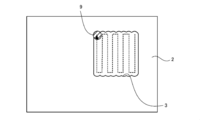
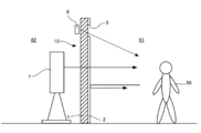
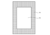
- FIG. 1 is a cross-sectional view taken along the line AA of FIG. It is a top view which shows the example of the environment where the glass body of FIG. 1 is used. It is an enlarged sectional view of the glass body in which a through hole was formed by a solution. It is a top view which shows the example of the removal of a coating layer by a laser. It is a side view which shows the example of the environment where the glass body of FIG. 1 is used. It is a top view which shows another example of the glass body which concerns on this invention. It is sectional drawing which shows the example of the glass body which attached the mirror LCD. It is a rear view which looked at the glass body of FIG. 7 from the 2nd area side.
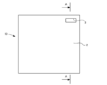
- FIG. 1 is a plan view of a glass body
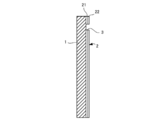
- FIG. 2 is a sectional view taken along line AA of FIG. 1
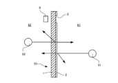
- FIG. 3 is a plan view of an environment in which the glass body is used.
- the glass body 10 includes a glass plate 1 and a coating layer 2 laminated on one surface thereof.
- the visible light transmittance and the visible light reflectance of the glass body 10 are adjusted by the coating layer 2, and the glass body 10 constitutes a so-called half mirror.
- the first area 61 and the second area 62 are formed with the glass body 10 interposed therebetween, the light from the first image 51 arranged in the first area 61 is emitted. Since the light is reflected on the surface of the glass body 10, the first image 51 is projected on the glass body 10.
- the glass plate 1 is not particularly limited, and a known glass plate can be used. For example, various glass plates such as float glass, heat ray absorbing glass, clear glass, green glass, UV green glass, and soda lime glass can be used.
- the thickness of the glass plate 1 is not particularly limited, but is preferably 0.5 to 10 mm, more preferably 0.7 to 8 mm, for example. Since the thickness of the glass plate 1 affects the above-mentioned visible light transmittance and visible light reflectance, it can be appropriately changed according to the required reflectance and transmittance.
- the coating layer 2 has a first layer 21 laminated on the glass plate 1 and a second layer 22 laminated on the first layer 21.
- additional layers such as a third layer and a fourth layer can be provided.
- the refractive index of the layer having the highest refractive index of the layers forming the coating layer 2 is, for example, preferably 1.6 or more, and more preferably 1.8 or more.
- the refractive index of the other layers is lower than this, for example, preferably 1.6 or less, and more preferably 1.5 or less.
- Each layer constituting the coating layer 2 can be formed of an inorganic metal oxide, for example, silicon (Si), silicon dioxide (SiO 2 ), tin oxide (SnO 2 ), titanium dioxide (TiO 2 ), SUS or From another suitable inorganic metal oxide, it is appropriately selected so as to satisfy the above-mentioned range of refractive index.
- the refractive indexes of silicon, silicon dioxide, tin oxide, titanium dioxide, and SUS are about 4.4, about 1.5, about 1.9, about 2.6, and about 2.9, respectively.
- the layer structure of the coating layer 2 is not particularly limited, but can be, for example, as follows. Further, in order to adjust the electrical resistance of each layer, additives can be appropriately doped.
- SiO 2 can be provided as a base layer between the first layer 21 and the glass plate 1. Further, when SUS is used, the visible light absorption rate can be improved. When the visible light absorptance is improved, the total value of the visible light reflectance and the visible light transmittance is reduced, so that the visible light reflectance and the visible light transmittance are easily adjusted.
- the film thickness of the coating layer 2 is preferably 3 to 50 nm, and more preferably 5 to 40 nm.
- the film thickness of the coating layer 2 is less than 10 nm, it becomes difficult to control the film thickness and the productivity is deteriorated. On the other hand, if it exceeds 50 nm, the cost may increase, the surface irregularities may become noticeable, the haze rate may increase, and the appearance may not be good.
- the film thickness of each layer constituting the coating layer 2 can be appropriately adjusted so that the film thickness of the coating layer 2 is within the above-mentioned range, and is not particularly limited.
- the film thickness of silicon can be about 18 nm and the film thickness of silicon dioxide can be about 30 nm.
- the film thickness of titanium dioxide in Examples 1 and 3 can be about 6 nm
- the film thickness of SUS in Example 5 can be about 8 nm.
- the visible light transmittance and visible light reflectance of the glass body 10 provided with the coating layer 2 are preferably 20% or more, more preferably 35% or more, and particularly preferably 40% or more. .. Since the visible light transmittance and the visible light reflectance are generally in a trade-off relationship, for example, it is preferable that the visible light transmittance and the visible light transmittance of the glass body 10 are the same values. However, either one of the visible light transmittance and the visible light reflectance can be increased, and it can be appropriately adjusted according to the required performance of the glass body. For example, the visible light reflectance can be adjusted to be higher than the visible light transmittance.
- the visible light transmittance and the visible light reflectance of such a glass body 10 can be adjusted by changing the material and film thickness constituting the coating layer 2 and the material and thickness of the glass plate 1.
- a* and b* can be adjusted by changing the material and the film thickness of the coating layer 2 and the material and the thickness of the glass plate 1, like the visible light transmittance and the visible light reflectance.
- the distance from the origin at the values of a * and b * is 3.2 to 6.5, it is said to be "a range that can be treated as the same color at the impression level".
- the reflection color difference level is equal to or lower than the transmission color difference level.
- the optical characteristics of the coating layer of Example 4 are shown below.
- the film thickness of the silicon of the first layer was 16 nm
- the film thickness of silicon dioxide was 38 nm
- the visible light transmittance and the visible light reflectance were measured by a spectrophotometer (U4100 manufactured by Hitachi, Ltd.).
- L *, a *, b * were calculated based on JIS Z8781.
- the light source was D65. The results are as follows.
- the color difference a * and b * in reflection is 6.5 or less.
- the color difference b * in transmission is large. Therefore, the color difference of reflection is smaller than the color difference of transmission.
- the film forming method of the coating layer 2 is not particularly limited, and for example, a so-called physical vapor deposition method such as a sputtering method or a vacuum vapor deposition method, a spray method, or a chemical vapor deposition method (CVD method) can be adopted.
- CVD method chemical vapor deposition method
- the online CVD method in the float method glass manufacturing process, a material for a coating layer is supplied from a coater onto a glass ribbon having a temperature of 615 ° C. or higher on a molten tin bath, and the coating layer 2 is subjected to a thermal decomposition oxidation reaction. It is one of the chemical vapor deposition methods to be formed.
- each layer of the coating layer 2 one material can be supplied from one coater, but when the film thickness of the layer is large, one layer is formed by two or more coaters. You can also. For example, in Example 4 above, when the film thickness of silicon is 18 nm and the film thickness of silicon dioxide is 30 nm, the first to third coaters are prepared, silicon is supplied by the first coater, and the second and third coaters are used.
- the coating layer 2 can be formed by supplying silicon dioxide.
- the above-mentioned SUS is formed by sputtering instead of CVD. Further, in order to form a thin material, it is preferable to use sputtering.
- the through hole 3 formed in the coating layer 2 exposes the glass plate 1 and is provided so that the light of a detection device such as a sensor or a camera can pass through the glass body 10.
- a detection device such as a sensor or a camera
- the first area 61 can be photographed through the through hole 3, that is, through the glass plate 1. ..
- the sensor can be arranged so that the light detected by the sensor passes through the through hole 3.
- the through hole 3 is a region where the glass plate 1 is exposed so that the light incident on or emitted from the sensor or the camera is transmitted.
- the portion where the through hole 3 is formed is the glass plate 1 itself, so that the visible light transmittance is 60% or more.
- the visible light transmittance can be 70% or more, and further 80% or more.
- the coating layer 2 needs to function as a half mirror as described above, it is preferable that the area of the through hole 3 be as small as possible, for example, 10000 mm 2 or less.
- the solution is not particularly limited as long as it can remove the coating layer 2 mainly formed of the inorganic oxide, but can be, for example, a potassium hydroxide solution.
- the concentration of potassium hydroxide in this solution can be, for example, more than 10% and less than 50%, and is preferably 25% or more and 40% or less. This is because if the concentration is 10% or less, it is difficult to react with the coating layer, and if the concentration is 50% or more, heat generation may occur.
- the immersion time can be, for example, 3 to 20 hours.
- sulfuric acid is suitable for removing the Ti layer of the coating layer 2
- hydrochloric acid is suitable for removing the Sn layer.
- Zn powder can be used as a catalyst.
- the mask member is not particularly limited as long as it has durability against a solution, but may be provided with, for example, a sheet-shaped base material and an adhesive material applied to one surface of the base material. Then, the base material is fixed to the coating layer 2 by the adhesive material. Both the base material and the pressure-sensitive adhesive may be durable to the solution, but at least the pressure-sensitive adhesive may be durable.
- the solution in addition to the method of immersing the glass body in the container in which the solution is stored, the solution can be dropped on the coating layer 2. However, in this case, the solution may evaporate. Therefore, the impregnating material impregnated with the solution can be brought into contact with the coating layer 2 exposed from the mask member.
- the impregnating material can be formed of, for example, a breathable woven fabric, a non-woven fabric, or the like. However, the impregnating material is preferably breathable. This is because water or the like may be generated as bubbles in the process of the reaction between the solution and the coating layer.
- bubbles When bubbles are generated, they may be released to the outside through the impregnating material, but if the bubbles are confined between the impregnating material and the coating layer, the removal of the coating layer 2 becomes insufficient. , There is a risk of unevenness.
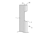
- the inner peripheral surface of the through hole 3 may be inclined so as to spread outward from the glass plate 1 as shown in FIG. 4, for example. .. Further, when the coating layer 2 is removed with a solution, the surface roughness of the exposed region on the glass plate 1 may be smaller than that of the unexposed region.
- the through hole 3 can be formed by heating the coating layer 2 with a laser such as a YAG laser and removing a part of the coating layer 2.
- a laser such as a YAG laser
- the coating layer 2 is removed by irradiating the coating layer 2 with a laser 9 having a circular cross section and moving it in a direction orthogonal to the laser 9 while reciprocating it in the plane direction.
- a rectangular through hole 3 can be formed.
- a dot laser can be adopted.
- the output of the laser can be, for example, 15 W or more, and the laser can be irradiated so as to form dots at a period of 50 KHz or less. Under such irradiation conditions, the through hole 3 can be reliably formed in the coating layer 2.
- the moving speed of the dot laser in the plane direction can be, for example, 100 to 900 mm / s. If the moving speed is less than 100 mm / s, the influence of the laser on the coating layer 2 becomes strong, and the coating layer 2 around the through hole 3 may be deteriorated. In addition, the glass plate 1 may break.
- the moving speed may be too fast and it may be difficult to form the through hole 2. That is, the output of the laser needs to be adjusted to such an extent that the coating layer 2 is heated and removed. Therefore, in order to prevent the glass plate 1 from cracking, for example, instead of completely removing the coating layer 2, it is possible to irradiate the laser so that a part of the coating layer 2 remains on the glass plate 1. ..
- the resistance value of the exposed region (second region) on the glass plate 1 may be 20 M ⁇ or more.
- the glass body configured as described above can be used in various ways, it can be used, for example, in a display system used in a sports gym or the like as described below.
- the glass body 10 is installed on the floor, and the user 58 who performs a dance exercise is arranged in the first area 61 sandwiching the glass body 10.
- a glass body having a visible light transmittance and a visible light reflectance adjusted to substantially the same level, for example, 30 to 40% is used.
- a display device 7 such as a display is arranged in the second area 62 sandwiching the glass body 10.
- the camera 8 is arranged at a position corresponding to the through hole 3.
- the display device 7 displays an example dance video.
- the dance video displayed on the display device 7 can be visually recognized by the user 58 in the first area 61 through the glass body 10.
- the user 58 can see his / her own image reflected on the glass body 10. That is, you can see your own dance with the glass body 10 as a mirror. Therefore, the user 58 can confirm his / her own dance while watching the video of the example dance.
- the visible light reflectance of the glass body 10 is adjusted to be higher than the visible light transmittance, the user can visually recognize his / her own dance more clearly. At this time, the image of the display device 7 looks a little unclear. However, if the distance between the display device 7 and the glass body 10 is shortened, the image of the display device 7 becomes clear.
- the display device 7 and the glass body 10 can be integrally fixed, which not only makes the image clearer but also facilitates transportation.
- the brightness of the image can be controlled by adjusting the light amount of the display device 7 and the transmission amount of the glass body 10.
- the user's dance can be confirmed or evaluated after the fact.
- the camera 8 and the display device 7 can be connected to each other to display the photographed evaluation of the dance on the display device 7 in real time. Further, for example, by inputting the output from the camera 8 into a position sensor system (not shown) and analyzing the image, the information of the camera 8 can be preferably provided to the user 58.
- the glass body 10 according to the present embodiment has the coating layer 2 whose visible light reflectance and visible light transmittance are adjusted, it can be used as a half mirror. Further, since the through hole 3 from which a part of the coating layer 2 is removed is formed and the glass plate 1 is exposed, the through hole 3 (glass plate 1) on the opposite side is provided by a device such as a sensor or a camera. Various areas can be detected, photographed, and the like.
- the glass body 10 since the glass body 10 is provided with the first region (portion other than the through hole) and the second region (portion of the through hole) having different optical characteristics, the glass body 10 has the first region. It is more compact than a display system that has only an area.
- the shape and position of the through hole 3 are not particularly limited, and can be appropriately changed as needed. Further, since the position of the coating layer 2 may be removed and the glass plate 1 may be exposed, for example, the exposed region of the present invention may be formed by the notch 3 as shown in FIG. 7.
- the shape of the glass plate 1 is not particularly limited, and various shapes are possible. Further, the coating layer 2 does not have to be formed over the entire surface of the glass plate 1, and may be formed in a required area on the glass plate 1. When the glass body is used in the above display system, the area of the glass body is preferably 1 m 2 or more.
- the glass body 10 is formed by forming the coating layer 2 on the glass plate 1, but the glass body 10 is not limited to this, and the glass body has visible light transmittance and visible light reflectance. It just needs to be adjusted. That is, a first region used as a half mirror and a second region for transmitting light of a camera or the like are formed on the glass body, and the first region used as a half mirror has a visible light transmittance and a visible light reflectance. Both are adjusted to be 20% or more, preferably 35% or more, and more preferably 40% or more. On the other hand, since the second region transmits the light of the camera or the sensor, the visible light transmittance is higher than that of the first region, and can be particularly 60% or more.
- a so-called mirror LCD 78 (for example, manufactured by Stanley Electric Co., Ltd.) can be provided on the glass body.
- the mirror LCD 78 can be used as an LCD when the power is turned on, and can display various images and moving images on a display surface, for example.
- the display surface functions as a mirror.
- the through hole 3 is formed according to the size of the display surface of the mirror LCD 78. At this time, the size of the through hole 3 can be made larger than that of the covering layer 2 depending on the size of the mirror LCD 78.
- a shielding layer 75 is laminated on the surface of the glass plate 1 on the second area 62 side so as to correspond to the region where the covering layer 2 is formed.
- the shielding layer 75 can be formed by a paint such as a dark pigment such as black or navy blue so that the wiring of the mirror LCD 78 cannot be seen from the first area 61 side.
- the thickness of the shielding layer 75 is not particularly limited, but may be 30 to 100 ⁇ m, for example.
- the shielding layer 75 can be made to have a warm color instead of a dark color.
- the color of the shielding layer 75 is -10 to 50 for chromaticity a *, -10 to 50 for chromaticity b *, and chromaticity L * in the L *, a *, b * color system (CIE standard).
- CIE standard color system
- the chromaticity a * is preferably 0 to 30, and more preferably 5 to 20.
- the chromaticity b * is preferably 0 to 30, and more preferably 5 to 20.
- the chromaticity L * is preferably 10 to 50, more preferably 10 to 30.
- a coating layer is formed on the glass plate.
- the coating layer is formed of two layers, the first layer is made of Si having a thickness of 24 nm, and the second layer is made of SiO 2 having a thickness of 30 nm.
- the mask member is attached to expose the region forming the through hole in the coating layer. Then, this region is removed by a solution. In the following, the coating layer was removed under various conditions.
- Solution contact method> Test 1 Two non-woven fabrics (Asahi Kasei Co., Ltd.) formed in the size of through-holes were used as an impregnating material, and the solution was dropped using a dropper.
- the solution is a potassium hydroxide solution with a concentration of 25%. Since this impregnating material is made by stacking two non-woven fabrics, it has breathability. This impregnating material was placed on the coating layer and left in an environment of 20 ° C. for 17 hours. As a result, the coating layer was sufficiently removed and through holes were formed.
- Test 2 The difference from Test 1 is the number of non-woven fabrics that make up the impregnating material. In Test 2, eight layers of non-woven fabric were used as the impregnating material, but the air permeability was not sufficient. This impregnating material was placed on the coating layer and left for 17 hours. As a result, air bubbles generated from the coating layer that reacted with the solution were confined between the impregnating material and the coating layer, so that the coating layer was not sufficiently removed and unevenness occurred.
- Test 3 The difference from Test 1 was that the solution was directly dropped on the coating layer without using the impregnating material and left for 17 hours. As a result, the solution evaporated and the coating layer could hardly be removed.
- the concentration of potassium hydroxide is preferably greater than 10%, preferably less than 50%, and preferably 25% or more and 40% or less.
- the coating layer was removed by substantially the same method as in Test 1. However, instead of the potassium hydroxide solution, an aqueous solution of hydrogen fluoride (hydrofluoric acid) was used as test 9, and an aqueous solution of sodium hydroxide was used as test 10. In each case, the concentration was set to 25% and the coating layer was sufficiently removed when it was left in an environment of 40° C. for 24 hours.
- Test 11 The coating layer was removed by substantially the same method as in Test 1. An impregnating material impregnated with an aqueous solution of hydrogen fluoride (hydrofluoric acid) having a concentration of 1% was used, and the mixture was left to stand in an environment of 20 ° C. for 10 minutes. Then, using an impregnating material impregnated with a potassium hydroxide aqueous solution having a concentration of 1%, the mixture was left at room temperature for 10 minutes. As a result, the coating layer could be sufficiently removed.
- hydrogen fluoride hydrofluoric acid
- a coating layer is formed on the glass plate.
- the coating layer is formed of three layers, the first layer is made of Si having a thickness of 25 nm, the second layer is made of SiO 2 having a thickness of 25 nm, and the third layer is made of SiO 2 having a thickness of 340 nm.
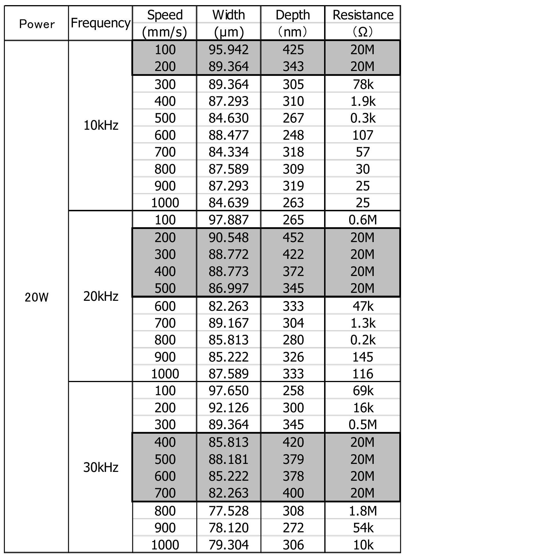
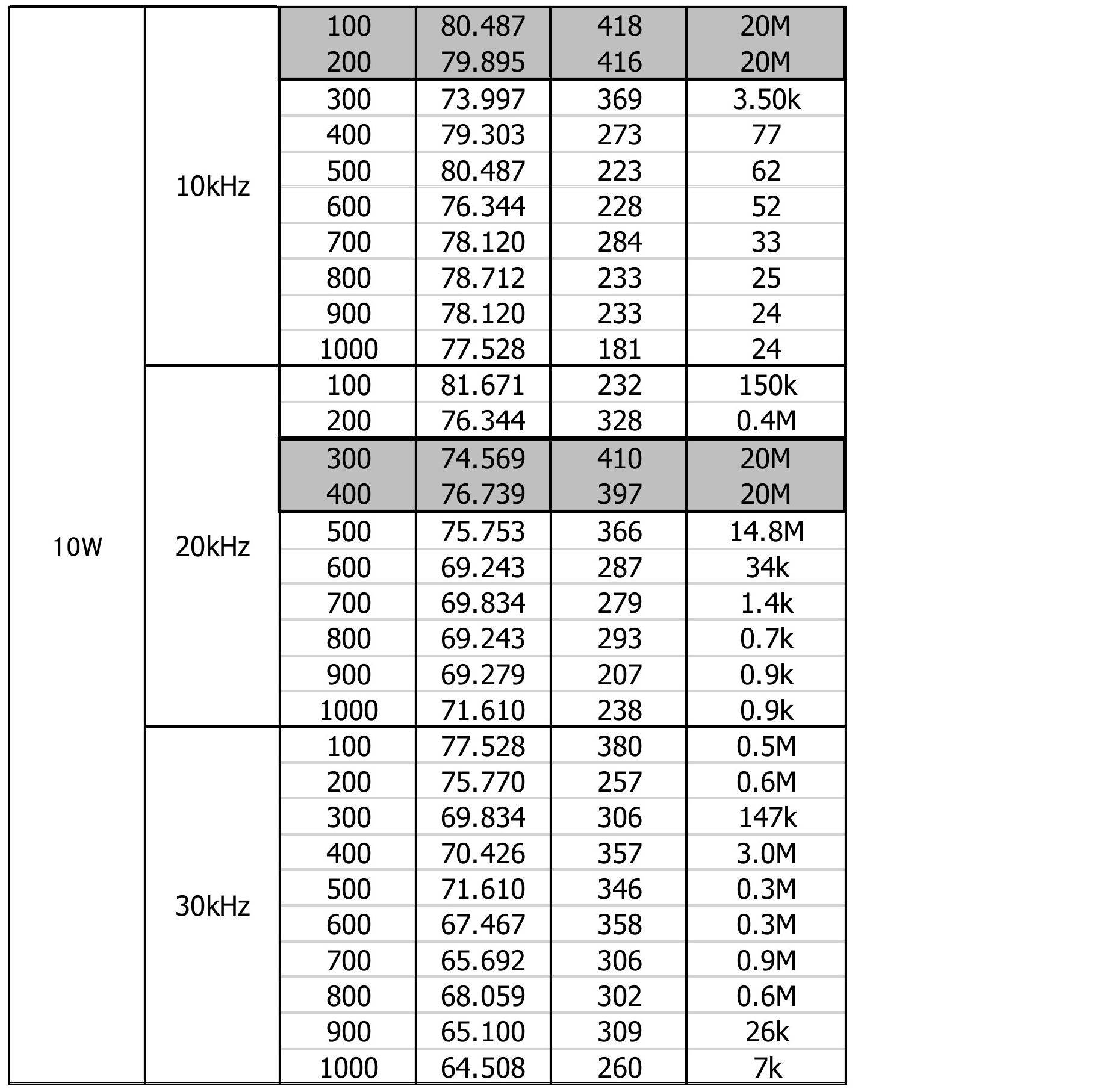
- the coating layer was removed by a laser device (MD-X1520 manufactured by KEYENCE CORPORATION) that irradiates a dot laser to form a through hole.
- the coating layer was sufficiently removed under the conditions colored in gray.
Landscapes
- Physics & Mathematics (AREA)
- Chemical & Material Sciences (AREA)
- Nonlinear Science (AREA)
- General Chemical & Material Sciences (AREA)
- Life Sciences & Earth Sciences (AREA)
- Geochemistry & Mineralogy (AREA)
- Materials Engineering (AREA)
- Organic Chemistry (AREA)
- Chemical Kinetics & Catalysis (AREA)
- Mathematical Physics (AREA)
- Crystallography & Structural Chemistry (AREA)
- Engineering & Computer Science (AREA)
- General Physics & Mathematics (AREA)
- Optics & Photonics (AREA)
- Surface Treatment Of Glass (AREA)
- Liquid Crystal (AREA)
Abstract
本発明に係る第1のガラス体は、可視光反射率及び可視光透過率が20%以上である第1領域と、前記第1領域よりも可視光透過率が高い第2領域と、を有している。
Description
本発明は、ガラス体、及びこれを用いた表示システムに関する。
特許文献1には、いわゆるハーフミラーと称するガラス体が開示されている。このガラス体は、ガラス板に無機酸化物を含有する被覆層を積層したものであり、可視光透過率と可視光反射率が調整されている。すなわち、ガラス体の一方側からガラス体を見ると、鏡のように像が映る一方、ガラス体の他方側にある像からの光が透過し、一方側からこれを見ることができる。
上記のようなハーフミラーは、種々の用途に利用されており、その用途も広がっている。例えば、ハーフミラーとセンサを合わせて用いることも考えられるが、ガラス板の表面には被覆層が形成されているため、例えば、センサから照射する光が透過しがたく、ガラス体の反対側の環境の検出ができないという問題があった。本発明は、上記問題を解決するためになされたものであり、ハーフミラーとして機能しつつ、センサ等の検出装置とともに用いることができる、ガラス体及び表示システムを提供することを目的とする。
本発明に係る第1のガラス体は、可視光反射率及び可視光透過率が20%以上である第1領域と、前記第1領域よりも可視光透過率が高い第2領域と、を有している。
上記第1のガラス体において、前記第2領域の可視光透過率は、60%以上とすることができる。
上記第1のガラス体においては、前記第2領域の面積を、10000mm2以下とすることができる。
上記第1のガラス体においては、前記第1領域の可視光透過率を、前記第1領域の可視光反射率よりも低くすることができる。
上記第1のガラス体においては、前記第2領域を複数設けることができる。
上記第1のガラス体において、前記第2領域は、矩形状に形成することができる。
本発明に係る第2のガラス体は、ガラス板と、前記ガラス板の一方の面側に積層される被覆層と、を備え、前記被覆層は、無機酸化物によって形成され、前記ガラス板よりも高い屈性率を有し、前記被複層には、前記ガラス板が露出する露出領域が形成されている。
上記第2のガラス体において、前記被覆層は、屈折率が1.6以上の第1層を有することができる。
上記第2のガラス体においては、前記第1層の膜厚を、3~50nmとすることができる。
上記第2のガラス体においては、前記第1層上に積層され、前記第1層より屈折率の低い第2層をさらに備えることができる。
上記第2のガラス体においては、前記第1層がSiを含有し、前記第2層がSiO2を含有するように構成することができる。
上記第2のガラス体においては、前記ガラス板と前記被覆層の間に、下地層を形成することができる。
上記第1のガラス体において、前記露出領域は、貫通孔または切り欠きによって形成することができ、前記貫通孔または切り欠きの縁部には凹凸が形成されるように構成することができる。
上記第1のガラス体において、前記露出領域には、前記無機酸化物の一部が残存するように構成することができる。
上記第1のガラス体において、前記被覆層において前記露出領域が形成されている箇所の内周面は、傾斜させることができる。
上記第1のガラス体において、前記ガラス板の露出領域の表面粗さは、当該露出領域の以外の領域の表面粗さと異なるように構成することができる。
上記第1のガラス体においては、前記第2領域の抵抗値を20MΩ以上とすることができる。
上記第1のガラス体においては、前記露出領域の抵抗値を20MΩ以上とすることができる。
上記第1のガラス体においては、前記第1領域に積層された遮蔽層をさらに備えることができる。
上記第1のガラス体においては、前記第2領域を囲むように前記第1領域を配置することができる。
上記第1のガラス体においては、前記第2領域を、前記第1領域よりも大きくすることができる。
上記第1のガラス体において、前記遮蔽層は、CIE規格の色度a*を-10~50、色度b*を-10~50、色度L*を10~100とすることができる。
上記第2のガラス体では、前記ガラス板の他方の面側において、前記被覆層と対応する部分に積層される遮蔽層をさらに備えることができる。
上記第2のガラス体においては、前記露出領域を囲むように前記被覆層を配置することができる。
上記第2のガラス体においては、前記露出領域を、前記被覆層よりも大きくすることができる。
上記第2のガラス体において、前記遮蔽層は、CIE規格の色度a*を-10~50、色度b*を-10~50、色度L*を10~100とすることができる。
本発明に係る表示システムは、上述したいずれかのガラス体と、前記ガラス体を挟んで、前記ガラス板側に配置される表示装置と、前記ガラス体を挟んで、前記ガラス板側に配置される検出装置と、を備え、前記検出装置は、前記露出領域を介して、前記ガラス体を挟んで、前記被覆層側に配置される物体の状態を検出するように構成されている。
上記表示システムにおいて、前記ガラス体の大きさは、1m2以上とすることができる。
本発明に係るガラス板の第1の製造方法は、ガラス板を準備する第1ステップと、前記ガラス板の一方の面に、前記ガラス板よりも高い屈性率を有し、無機酸化物によって形成された被覆層を積層する第2ステップと、前記無機酸化物と化学的に反応可能な反応溶液を前記被覆層の一部の箇所に、所定時間接触させることで、当該箇所を除去し、前記ガラス板が露出する露出領域を形成する第3ステップと、を備えている。
上記ガラス板の第1の製造方法において、前記第3ステップに先立って、前記被覆層に、前記箇所が露出するようにマスク部材を配置するステップを、さらに備えることができる。
上記ガラス板の第1の製造方法において、前記マスク部材は、基材と、当該基材を前記被覆層に固定するための粘着材と、を備えることができ、少なくとも前記粘着材は、前記反応溶液に対し耐久性を有するものとすることができる。
上記ガラス板の第1の製造方法では、前記第3ステップにおいては、前記反応溶液が含浸された含浸材を、前記箇所に接触させることができる。
上記ガラス板の第1の製造方法では、前記含浸材は通気性を有することができる。
上記ガラス板の第1の製造方法では、前記反応溶液は、少なくとも水酸化カリウムを含有する溶液とすることができる。
上記ガラス板の第1の製造方法では、前記反応溶液における前記水酸化カリウムの濃度は、10%より多く、50%未満とすることができる。
上記ガラス板の第1の製造方法では、前記第3ステップに先立って、前記箇所に、フッ化水素を接触させるステップをさらに備えることができる。
本発明に係るガラス板の第2の製造方法は、ガラス板を準備する第1ステップと、前記ガラス板の一方の面に、前記ガラス板よりも高い屈性率を有する被覆層を積層する第2ステップと、前記被覆層の一部の箇所にドットレーザを照射することで、当該箇所を除去し、前記ガラス板が露出する露出領域を形成する第3ステップと、を備えている。
上記ガラス板の第2の製造方法では、前記ドットレーザの出力は15W以上であり、50KHz以下の周期でドットが形成されるものとすることができる。
上記ガラス板の第2の製造方法では、前記ガラス板の面方向に、前記ドットレーザを100~900mm/sの速度で移動することで、前記箇所を除去することができる。
本発明によれば、ハーフミラーとして機能しつつ、センサ等の検出装置とともに用いることができる。
以下、本発明に係るガラス体及びこれを用いた表示システムの一実施形態について、図面を参照しつつ説明する。図1はガラス体の平面図、図2は図1のA-A線断面図、図3はこのガラス体が利用される環境の平面図である。
<1.ガラス体の概要>
図1及び図2に示すように、このガラス体10は、ガラス板1と、その一方の面に積層された被覆層2と、を備えている。被覆層2によって、ガラス体10の可視光透過率及び可視光反射率が調整されており、ガラス体10は、いわゆるハーフミラーを構成している。例えば、図3に示すように、ガラス体10を挟んで第1区域61及び第2区域62が形成されているとすると、第1区域61に配置された第1の像51からの光は、ガラス体10の表面で反射するため、ガラス体10には第1の像51が映る。その一方で、第2区域62に配置された第2の像52からの光は、ガラス体10を透過するため、第1区域61から第2区域62にある第2の像52を視認することができる。また、被覆層2には矩形状の貫通孔3が形成されており、この貫通孔3からガラス板1が露出している。以下、これらについて詳細に説明する。
図1及び図2に示すように、このガラス体10は、ガラス板1と、その一方の面に積層された被覆層2と、を備えている。被覆層2によって、ガラス体10の可視光透過率及び可視光反射率が調整されており、ガラス体10は、いわゆるハーフミラーを構成している。例えば、図3に示すように、ガラス体10を挟んで第1区域61及び第2区域62が形成されているとすると、第1区域61に配置された第1の像51からの光は、ガラス体10の表面で反射するため、ガラス体10には第1の像51が映る。その一方で、第2区域62に配置された第2の像52からの光は、ガラス体10を透過するため、第1区域61から第2区域62にある第2の像52を視認することができる。また、被覆層2には矩形状の貫通孔3が形成されており、この貫通孔3からガラス板1が露出している。以下、これらについて詳細に説明する。
<1-1.ガラス板>
ガラス板1は、特には限定されず、公知のガラス板を用いることができる。例えば、フロートガラス、熱線吸収ガラス、クリアガラス、グリーンガラス、UVグリーンガラス、ソーダライムガラスなど種々のガラス板を用いることができる。ガラス板1の厚みは、特には限定されないが、例えば、0.5~10mmとすることが好ましく、0.7~8mmとすることがさらに好ましい。ガラス板1の厚みは、上述した可視光透過率及び可視光反射率に影響を与えるため、要求される反射率及び透過率に応じて適宜変更することができる。
ガラス板1は、特には限定されず、公知のガラス板を用いることができる。例えば、フロートガラス、熱線吸収ガラス、クリアガラス、グリーンガラス、UVグリーンガラス、ソーダライムガラスなど種々のガラス板を用いることができる。ガラス板1の厚みは、特には限定されないが、例えば、0.5~10mmとすることが好ましく、0.7~8mmとすることがさらに好ましい。ガラス板1の厚みは、上述した可視光透過率及び可視光反射率に影響を与えるため、要求される反射率及び透過率に応じて適宜変更することができる。
<1-2.被覆層>
図2に示すように、被覆層2は、ガラス板1上に積層される第1層21と、第1層21上に積層される第2層22とを有している。但し、必要に応じて、第3層、第4層等、追加の層を設けることもできる。被覆層2を構成する層のうち、最も屈折率の高い層の屈折率は、例えば、1.6以上であることが好ましく、1.8以上であることがさらに好ましい。その他の層の屈折率は、これよりも低く、例えば、1.6以下であることが好ましく、1.5以下であることがさらに好ましい。
図2に示すように、被覆層2は、ガラス板1上に積層される第1層21と、第1層21上に積層される第2層22とを有している。但し、必要に応じて、第3層、第4層等、追加の層を設けることもできる。被覆層2を構成する層のうち、最も屈折率の高い層の屈折率は、例えば、1.6以上であることが好ましく、1.8以上であることがさらに好ましい。その他の層の屈折率は、これよりも低く、例えば、1.6以下であることが好ましく、1.5以下であることがさらに好ましい。
被覆層2を構成する各層は、無機金属酸化物によって形成することができ、例えば、シリコン(Si)、二酸化ケイ素(SiO2)、酸化スズ(SnO2)、二酸化チタン(TiO2)、SUSまたは別の好適な無機金属酸化物から、上述した屈折率の範囲を満たすように、適宜選択される。例えば、シリコン、二酸化ケイ素、酸化スズ、二酸化チタン、SUSの屈折率は、それぞれ、約4.4,約1.5、約1.9、約2.6、約2.9である。被覆層2の層構成は、特には限定されないが、例えば、以下のようにすることができる。また、各層の電気抵抗を調整するため、添加物を適宜、ドープすることもできる。

なお、例1及び例3では、第1層21とガラス板1との間に下地層としてSiO2を設けることができる。また、SUSを用いると、可視光吸収率が向上することができる。可視光吸収率が向上すると、可視光反射率と可視光透過率の合計値が低減するため、可視光反射率と可視光透過率の調整が容易になる。
被覆層2の膜厚は、3~50nmであることが好ましく、5~40nmであることがさらに好ましい。被覆層2の膜厚が10nm未満となると、膜厚の制御が困難になり生産性が悪くなるという問題が生じる。一方、50nmを超えると、コストが高くなったり、表面の凹凸が顕著になりやヘイズ率が上昇し見栄えがよくない可能性がある。また、被覆層2を構成する各層の膜厚は、被覆層2の膜厚が上述した範囲となるように適宜調整することができ、特には限定されない。例えば、上記例4においては、シリコンの膜厚を約18nm、二酸化ケイ素の膜厚を約30nmとすることができる。その他、例1及び例3の二酸化チタンの膜厚は、約6nm、例5のSUSの膜厚は、約8nmとすることができる。
被覆層2を設けることによるガラス体10の可視光透過率及び可視光反射率は、20%以上であることが好ましく、35%以上であることがさらに好ましく、40%以上であることが特に好ましい。可視光透過率と可視光反射率は、概ねトレードオフの関係にあるため、例えば、ガラス体10の可視光反射率及び可視光透過率が同等の値であることが好ましい。但し、可視光透過率及び可視光反射率のいずれか一方が大きくなるようにすることもでき、要求されるガラス体の性能によって適宜調整することができる。例えば、可視光反射率が可視光透過率より高くなるように調整することができる。
このようなガラス体10の可視光透過率及び可視光反射率は、被覆層2を構成する材料や膜厚、ガラス板1の材料や厚みを変更することで調整することができる。
また、ガラス体10の色目が変化すると好ましくない場合がある。したがって、L*,a*,b*表色系において、ガラス体10のa*及びb*の値における原点、すなわちa*=0、b*=0からの距離が、±6.5以内であることが好ましく、±3.2以下であることがさらに好ましい。これらa*及びb*は、可視光透過率及び可視光反射率と同様に、被覆層2を構成する材料や膜厚、ガラス板1の材料や厚みを変更することで調整することができる。一般的に、a*及びb*の値における原点からの距離が3.2~6.5であれは、「印象レベルで同じいろと扱える範囲」と言われている。また、一般的に、a*及びb*の値における原点からの距離が3.2以下であれば、色の離間比較では、ほとんど気づかれない色差レベルと言われている。なお、後述する表示システムにおいては、表示装置において色調の調整が可能であるため、反射の色差レベルが重要であり、透過レベルの重要度は高くない。したがって、後述する表示システムのような利用方法においては、反射の色差レベルが、透過の色差レベル以下であることが好ましい。
以下に、上記例4の被覆層の光学特性を示す。第1層のシリコンの膜厚を16nm、二酸化ケイ素の膜厚を38nmとし、分光光度計(日立製作所製U4100)によって、可視光透過率及び可視光反射率を測定した。L*,a*,b*は、JIS Z8781に基づいて算出した。また、光源はD65とした。結果は、以下の通りである。
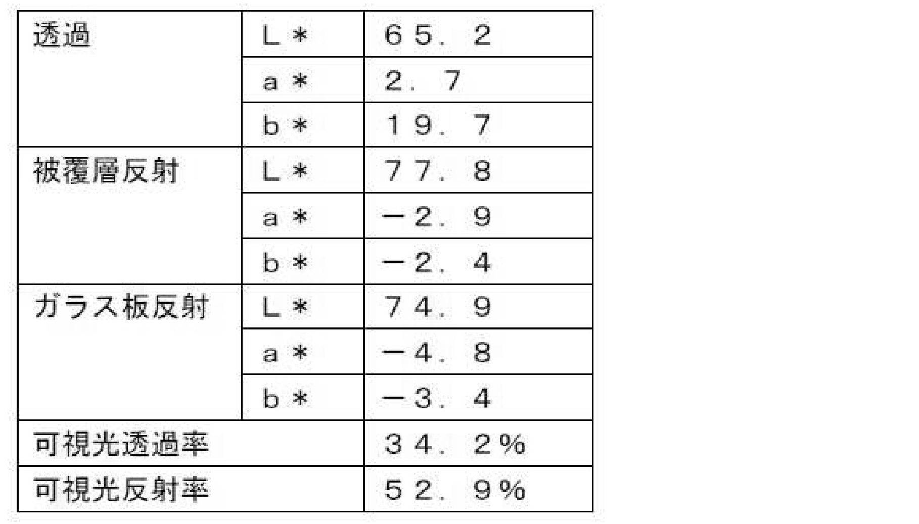
以上の光学特性によれば、反射における色差a*,b*は6.5以下となっている。また、透過における色差b*が大きくなっている。したがって、反射の色差が、透過の色差よりも小さくなっている。
<1-3.被覆層の成膜>
次に、被覆層2の成膜について説明する。被覆層2の成膜方法は特には限定されないが、例えば、スパッタリング法、真空蒸着法などのいわゆる物理蒸着法、スプレー法、あるいは、化学気相法(CVD法)を採用することができる。特に、CVD法を採用する場合、オンラインCVD法を採用することが好ましい。オンラインCVD法とは、フロート法ガラス製造工程において、溶融錫浴上にある温度が615℃以上のガラスリボン上に、コーターから被覆層用の材料を供給し、熱分解酸化反応により被覆層2を形成する化学蒸着法の一つである。
次に、被覆層2の成膜について説明する。被覆層2の成膜方法は特には限定されないが、例えば、スパッタリング法、真空蒸着法などのいわゆる物理蒸着法、スプレー法、あるいは、化学気相法(CVD法)を採用することができる。特に、CVD法を採用する場合、オンラインCVD法を採用することが好ましい。オンラインCVD法とは、フロート法ガラス製造工程において、溶融錫浴上にある温度が615℃以上のガラスリボン上に、コーターから被覆層用の材料を供給し、熱分解酸化反応により被覆層2を形成する化学蒸着法の一つである。
被覆層2の各層を成膜するには、1つのコーターから1つの材料を供給することができるが、層の膜厚が大きい場合には、2以上のコーターによって1つの層を成膜することもできる。例えば、上記例4において、シリコンの膜厚が18nm、二酸化ケイ素の膜厚が30nmである場合、第1~第3コーターを準備し、第1コーターによりシリコンを供給し、第2及び第3コーターにより二酸化ケイ素を供給することで、被覆層2の成膜を行うことができる。
なお、上述したSUSは、CVDではなく、スパッタリングにより成膜される。また、膜厚が薄い材料を成膜するには、スパッタリングを用いることが好ましい。
<1-4.貫通孔>
被覆層2に形成される貫通孔3は、ガラス板1を露出させるものであり、センサ、カメラ等の検出装置の光がガラス体10を透過できるようにするために設けられるものである。例えば、図3の第2区域62に配置されたカメラ8によって第1区域61を撮影するとき、貫通孔3を介して、つまりガラス板1を介して第1区域61の撮影を行うことができる。同様に、センサで検知する光が貫通孔3を通過するように、センサを配置することができる。このように、貫通孔3は、センサやカメラに入射したり、あるいは出射する光が透過するように、ガラス板1が露出する領域である。したがって、ガラス体10において、貫通孔3の形成されている部分は、ガラス板1そのものであるため、可視光透過率は、60%以上となる。なお、ガラス板1の種類や厚みによっては、可視光透過率は70%以上、さらには80%以上とすることも可能である。
被覆層2に形成される貫通孔3は、ガラス板1を露出させるものであり、センサ、カメラ等の検出装置の光がガラス体10を透過できるようにするために設けられるものである。例えば、図3の第2区域62に配置されたカメラ8によって第1区域61を撮影するとき、貫通孔3を介して、つまりガラス板1を介して第1区域61の撮影を行うことができる。同様に、センサで検知する光が貫通孔3を通過するように、センサを配置することができる。このように、貫通孔3は、センサやカメラに入射したり、あるいは出射する光が透過するように、ガラス板1が露出する領域である。したがって、ガラス体10において、貫通孔3の形成されている部分は、ガラス板1そのものであるため、可視光透過率は、60%以上となる。なお、ガラス板1の種類や厚みによっては、可視光透過率は70%以上、さらには80%以上とすることも可能である。
但し、被覆層2は、上記のようなハーフミラーとしての機能を果たす必要があるため、貫通孔3の面積はできるだけ小さいことが好ましく、例えば、10000mm2以下とすることができる。
次に、貫通孔の形成方法について説明する。以下では、2種類の貫通孔の形成方法について説明するが、ガラス板を露出できるように被覆層に貫通孔を形成できるのであれば、以下の方法に限定されない。
<1-4-1.溶液による貫通孔の形成>
まず、被覆層2において、貫通孔3を形成する箇所の周囲をマスク部材によって覆う。これにより、被覆層2において、貫通孔3を形成する部分が露出する。続いて、このガラス体を溶液が溜められた容器に浸漬し、この溶液によって露出した被覆層2を除去する。これにより、被覆層2に貫通孔3が形成され、ガラス板1が露出する。
まず、被覆層2において、貫通孔3を形成する箇所の周囲をマスク部材によって覆う。これにより、被覆層2において、貫通孔3を形成する部分が露出する。続いて、このガラス体を溶液が溜められた容器に浸漬し、この溶液によって露出した被覆層2を除去する。これにより、被覆層2に貫通孔3が形成され、ガラス板1が露出する。
溶液は、主として無機酸化物で形成された被覆層2を除去できるものであれば、特には限定されないが、例えば、水酸化カリウム溶液とすることができる。この溶液における水酸化カリウムの濃度は、例えば、10%より大きく50%未満とすることができ、25%以上40%以下であることが好ましい。これは、濃度が10%以下であれば、被覆層と反応しがたくなるからであり、50%以上であれば、発熱のおそれがあることによる。また、浸漬時間は、例えば、3~20時間とすることができる。
なお、ガラス体を溶液に浸漬するのに先立って、露出した被覆層2にフッ化水素を接触させる前処理を設けることもできる。すなわち、フッ化水素によって被覆層2の一部または概ね全体を除去しておけば、水酸化カリウム溶液への浸漬時間を短くすることができる。但し、フッ化水素のみによって被覆層2を除去すると、ガラス板1の表面が溶解するおそれがあるため、好ましくない。
また、水酸化カリウム溶液に限られず、被覆層2のTi層を除去するには硫酸が好適であり、Sn層を除去するには塩酸が好適である。また、必要に応じて、Znの粉末を触媒として用いることもできる。
マスク部材は、溶液への耐久性があれば特には限定されないが、例えば、シート状の基材と、この基材の一方の面に塗布される粘着材とを備えるものとすることができる。そして、粘着材により基材が被覆層2に固定される。基材及び粘着材の両方が溶液に対する耐久性があればよいが、少なくとも粘着材に耐久性があればよい。
また、溶液が溜められた容器にガラス体を浸漬させる方法のほか、溶液を被覆層2上に滴下することもできる。但し、この場合には、溶液が蒸発するおそれがある。そこで、溶液を含浸した含浸材を、マスク部材から露出した被覆層2に接触させることができる。含浸材は、例えば、通気性を有する織布、不織布等で形成することができる。但し、含浸材は、通気性を有することが好ましい。これは、溶液と被覆層との反応の過程で、水分等が泡として発生することがあるためである。泡が発生した場合、これが含浸材を通過して外部に放出されればよいが、泡が含浸材と被覆層との間で閉じ込められた場合には、被覆層2の除去が不十分になり、ムラが生じるおそれがある。
このような溶液によって被覆層2を除去した場合、貫通孔3の内周面は、例えば、図4に示すように、ガラス板1から外部に向かって裾広がりになるように傾斜することがある。また、溶液によって被覆層2を除去した場合、ガラス板1において露出した領域の表面粗さが、露出していない領域よりも小さくなることがある。
<1-4-2.レーザによる貫通孔の形成>
被覆層2が成膜された後、YAGレーザ等のレーザによって被覆層2を加熱し、被覆層2の一部を除去することで貫通孔3を形成することができる。例えば、図5に示すように、断面が円形のレーザー9を被覆層2に照射し、これを面方向に往復動させつつ、これと直交する方向に移動させることで、被覆層2を除去し、矩形状の貫通孔3を形成することができる。このように円形のレーザ光を移動させると、貫通孔3の内縁には凹凸が形成される。
被覆層2が成膜された後、YAGレーザ等のレーザによって被覆層2を加熱し、被覆層2の一部を除去することで貫通孔3を形成することができる。例えば、図5に示すように、断面が円形のレーザー9を被覆層2に照射し、これを面方向に往復動させつつ、これと直交する方向に移動させることで、被覆層2を除去し、矩形状の貫通孔3を形成することができる。このように円形のレーザ光を移動させると、貫通孔3の内縁には凹凸が形成される。
レーザとしては、例えば、ドットレーザを採用することができる。レーザの出力は、例えば、15W以上とすることができ、50KHz以下の周期でドットを形成するようにレーザを照射することができる。このような照射条件とすることで、被覆層2に確実に貫通孔3を形成することができる。また、ドットレーザの面方向の移動速度は、例えば、100~900mm/sとすることができる。移動速度が100mm/s未満であると、被覆層2に対するレーザの影響が強くなり、貫通孔3の周辺の被覆層2が変質するおそれがある。また、ガラス板1が割れるおそれもある。一方、900mm/sを超えると、移動速度が速すぎて貫通孔2を形成しがたくなるおそれがある。すなわち、レーザの出力は、被覆層2を加熱して除去する程度に調整する必要がある。したがって、ガラス板1の割れを防止するために、例えば、被覆層2を完全に除去するのではなく、被覆層2の一部がガラス板1上に残存するようにレーザを照射することもできる。
このようにレーザを用いて被覆層2を除去した場合、ガラス板1において露出した領域(第2領域)の抵抗値が20MΩ以上となることがある。
<2.ガラス体の利用方法>
上記のように構成されたガラス体は、種々の利用方法があるが、例えば、以下のようにスポーツジムなどで利用する表示システムに利用することができる。図6に示すように、床にガラス体10を設置し、ガラス体10を挟んだ第1区域61にダンスのエクササイズを行う利用者58を配置する。ここで利用するガラス体10は、可視光透過率と可視光反射率が概ね同じ程度、例えば、30~40%程度に調整したものを用いる。そして、ガラス体10を挟んだ第2区域62には、ディスプレイ等の表示装置7を配置する。また、貫通孔3と対応する位置にはカメラ8を配置する。そして、表示装置7には、例となるダンスのビデオを表示する。
上記のように構成されたガラス体は、種々の利用方法があるが、例えば、以下のようにスポーツジムなどで利用する表示システムに利用することができる。図6に示すように、床にガラス体10を設置し、ガラス体10を挟んだ第1区域61にダンスのエクササイズを行う利用者58を配置する。ここで利用するガラス体10は、可視光透過率と可視光反射率が概ね同じ程度、例えば、30~40%程度に調整したものを用いる。そして、ガラス体10を挟んだ第2区域62には、ディスプレイ等の表示装置7を配置する。また、貫通孔3と対応する位置にはカメラ8を配置する。そして、表示装置7には、例となるダンスのビデオを表示する。
これにより、表示装置7に表示されるダンスのビデオは、ガラス体10を透過して第1区域61にいる利用者58が視認することができる。また、利用者58は、ガラス体10に反射した自身の像を見ることができる。すなわち、ガラス体10を鏡として自身のダンスを見ることができる。したがって、利用者58は、例となるダンスのビデオを見ながら、自身のダンスを確認することができる。
なお、ガラス体10の可視光反射率が可視光透過率より高くなるように調整されていれば、利用者は自身のダンスをより明確に視認することができる。このとき、表示装置7の映像は、やや不明瞭に見えることになる。但し、表示装置7とガラス体10との距離が短くなれば、表示装置7の映像が鮮明になる。なお、表示装置7とガラス体10とを一体的に固定することもでき、こうすることで、映像が鮮明になるだけでなく、搬送が容易になる。また、表示装置7の光量を調整するとともに、ガラス体10の透過量を調整することで、映像の輝度を制御可能である。
さらに、貫通孔3を介してカメラ8で利用者のダンスを撮影することで、事後的に利用者のダンスを確認したり、あるいは評価することができる。また、カメラ8と表示装置7を接続し、撮影された利用者のダンスに対する評価をリアルタイムで表示装置7に表示することもできる。また、例えば、カメラ8からの出力を、図示しない位置センサーシステムに入力し、画像を解析することで、好適に、カメラ8の情報を利用者58に提供することも可能である。
<3.特徴>
本実施形態に係るガラス体10は、可視光反射率及び可視光透過率が調整された被覆層2を有しているため、ハーフミラーとして利用することができる。また、被覆層2の一部を除去した貫通孔3が形成され、ガラス板1が露出しているため、この貫通孔3(ガラス板1)を介してセンサやカメラ等の装置によって反対側の領域の種々の検知、撮影等を行うことができる。
本実施形態に係るガラス体10は、可視光反射率及び可視光透過率が調整された被覆層2を有しているため、ハーフミラーとして利用することができる。また、被覆層2の一部を除去した貫通孔3が形成され、ガラス板1が露出しているため、この貫通孔3(ガラス板1)を介してセンサやカメラ等の装置によって反対側の領域の種々の検知、撮影等を行うことができる。
また、本実施形態に係る表示システムは、ガラス体10に光学特性の異なる第1領域(貫通孔以外の部分)と第2領域(貫通孔の部分)を設けているので、ガラス体に第1領域しかない表示システムに比してコンパクトになる。
<4.変形例>
以上、本発明の一実施形態について説明したが、本発明は上記実施形態に限定されるものではなく、その趣旨を逸脱しない限りにおいて、種々の変更が可能である。なお、以下の変形例は適宜組み合わせることができる。
以上、本発明の一実施形態について説明したが、本発明は上記実施形態に限定されるものではなく、その趣旨を逸脱しない限りにおいて、種々の変更が可能である。なお、以下の変形例は適宜組み合わせることができる。
<4-1>
貫通孔3の形状、位置は特には限定されず、必要に応じて適宜変更することができる。また、被覆層2の位置が除去され、ガラス板1が露出していればよいため、例えば、図7に示すような切り欠き3によって本発明の露出領域を構成してもよい。
貫通孔3の形状、位置は特には限定されず、必要に応じて適宜変更することができる。また、被覆層2の位置が除去され、ガラス板1が露出していればよいため、例えば、図7に示すような切り欠き3によって本発明の露出領域を構成してもよい。
<4-2>
ガラス板1の形状は特には限定されず、種々の形状が可能である。また、被覆層2は、ガラス板1の全面に亘って形成する必要はなく、ガラス板1において必要な面積に形成すればよい。上記のような表示システムにガラス体を用いる場合には、ガラス体の面積を1m2以上とすることが好ましい。
ガラス板1の形状は特には限定されず、種々の形状が可能である。また、被覆層2は、ガラス板1の全面に亘って形成する必要はなく、ガラス板1において必要な面積に形成すればよい。上記のような表示システムにガラス体を用いる場合には、ガラス体の面積を1m2以上とすることが好ましい。
<4-3>
上記実施形態では、ガラス板1に被覆層2を形成することでガラス体10を構成しているが、これに限定されるものではなく、ガラス体として、可視光透過率及び可視光反射率が調整されていればよい。すなわち、ガラス体にハーフミラーとして利用する第1領域と、カメラ等の光を透過させる第2領域とを形成し、ハーフミラーとして利用する第1領域は、可視光透過率及び可視光反射率がともに20%以上、好ましくは35%以上、さらに好ましくは40%以上となるように調整する。一方、第2領域は、カメラやセンサの光を透過させるため、可視光透過率が第1領域よりも高くし、特に60%以上することができる。
上記実施形態では、ガラス板1に被覆層2を形成することでガラス体10を構成しているが、これに限定されるものではなく、ガラス体として、可視光透過率及び可視光反射率が調整されていればよい。すなわち、ガラス体にハーフミラーとして利用する第1領域と、カメラ等の光を透過させる第2領域とを形成し、ハーフミラーとして利用する第1領域は、可視光透過率及び可視光反射率がともに20%以上、好ましくは35%以上、さらに好ましくは40%以上となるように調整する。一方、第2領域は、カメラやセンサの光を透過させるため、可視光透過率が第1領域よりも高くし、特に60%以上することができる。
<4-4>
図8及び図9に示すように、ガラス体にいわゆるミラーLCD78(例えば、スタンレー電気株式会社製)を設けることができる。ミラーLCD78は、例えば、電源をONにしたときにLCDとして使用でき、表示面に種々の画像、動画を表示することできるものである。一方、電源をOFFにした場合には、表示面が鏡として機能する。このようなミラーLCDを利用する場合、ミラーLCD78の表示面の大きさに合わせて貫通孔3を形成する。このとき、ミラーLCD78の大きさにもよるが、貫通孔3の大きさを、被覆層2よりも大きくすることができる。そして、ガラス板1の第2区域62側の面には、被覆層2が形成されている領域と対応するように遮蔽層75を積層する。この遮蔽層75は、ミラーLCD78の配線等が、第1区域61側から見えないように黒、紺等の濃色の顔料などの塗料により形成することができる。遮蔽層75の厚みは、特には限定されないが、例えば、30~100μmとすることができる。
図8及び図9に示すように、ガラス体にいわゆるミラーLCD78(例えば、スタンレー電気株式会社製)を設けることができる。ミラーLCD78は、例えば、電源をONにしたときにLCDとして使用でき、表示面に種々の画像、動画を表示することできるものである。一方、電源をOFFにした場合には、表示面が鏡として機能する。このようなミラーLCDを利用する場合、ミラーLCD78の表示面の大きさに合わせて貫通孔3を形成する。このとき、ミラーLCD78の大きさにもよるが、貫通孔3の大きさを、被覆層2よりも大きくすることができる。そして、ガラス板1の第2区域62側の面には、被覆層2が形成されている領域と対応するように遮蔽層75を積層する。この遮蔽層75は、ミラーLCD78の配線等が、第1区域61側から見えないように黒、紺等の濃色の顔料などの塗料により形成することができる。遮蔽層75の厚みは、特には限定されないが、例えば、30~100μmとすることができる。
但し、遮蔽層75の内縁、つまり遮蔽層75と遮蔽層75が積層されていない領域との境界が目立つのを抑制するため、遮蔽層75を濃色ではなく、暖色等にすることもできる。例えば、遮蔽層75の色を、L*,a*,b*表色系(CIE規格)において、色度a*が-10~50,色度b*が-10~50,色度L*が10~100とすることができる。色度a*は、0~30が好ましく、5~20がさらに好ましい。色度b*は、0~30が好ましく、5~20がさらに好ましい。また、色度L*は、10~50が好ましく、10~30がさらに好ましい。これにより、第1区域61側から見たときに遮蔽層75の境界が目立つのを抑制することができるとともに、例えば、鏡として用いたときに、映った肌色がきれいに見える。なお、第2区域62側に配置されたセンサの光が透過可能な他の貫通孔を被覆層2に設けることもできる。
以下、本発明の実施例について説明する。但し、本発明は、以下の実施例に限定されない。
<1.溶液による貫通孔の形成>
以下、溶液による貫通孔の形成について説明する。まず、ガラス板に、被覆層を形成する。被覆層は2層により形成され、第1層が24nmの厚みのSi、第2層が30nmの厚みのSiO2により形成されている。次に、マスク部材を取り付け、被覆層において、貫通孔を形成する領域を露出させる。そして、この領域を溶液によって除去する。以下では、種々の条件により被覆層を除去した。
以下、溶液による貫通孔の形成について説明する。まず、ガラス板に、被覆層を形成する。被覆層は2層により形成され、第1層が24nmの厚みのSi、第2層が30nmの厚みのSiO2により形成されている。次に、マスク部材を取り付け、被覆層において、貫通孔を形成する領域を露出させる。そして、この領域を溶液によって除去する。以下では、種々の条件により被覆層を除去した。
<1-1.溶液の接触方法>
試験1:貫通孔の大きさに形成した不織布(旭化成株式会社ベンコット)を2枚重ねたものを含浸材として用い、これにスポイトによって溶液を滴下した。溶液は、濃度が25%の水酸化カリウム溶液である。この含浸材は、不織布を2枚重ねたものであるため、通気性を有する。この含浸材を被覆層上に配置し、20℃の環境下で、17時間放置した。その結果、被覆層が十分に除去され、貫通孔が形成された。
試験1:貫通孔の大きさに形成した不織布(旭化成株式会社ベンコット)を2枚重ねたものを含浸材として用い、これにスポイトによって溶液を滴下した。溶液は、濃度が25%の水酸化カリウム溶液である。この含浸材は、不織布を2枚重ねたものであるため、通気性を有する。この含浸材を被覆層上に配置し、20℃の環境下で、17時間放置した。その結果、被覆層が十分に除去され、貫通孔が形成された。
試験2:試験1との相違は、含浸材を構成する不織布の枚数である。試験2では、不織布を8枚重ねたものを含浸材として用いたが、通気性が十分ではなかった。この含浸材を被覆層上に配置し、17時間放置した。その結果、溶液と反応した被覆層から発生する気泡が含浸材と被覆層との間に閉じ込められたため、被覆層が十分に除去されず、ムラが生じた。
試験3:試験1との相違は、含浸材を用いず、被覆層上に溶液を直接滴下して、17時間放置した。その結果、溶液が蒸発してしまい、被覆層がほとんど除去できなかった。
<1-2.溶液の濃度>
試験1と概ね同じ方法で被覆層を除去した。但し、水酸化カリウム溶液の濃度を変更した。結果は、以下の通りである。
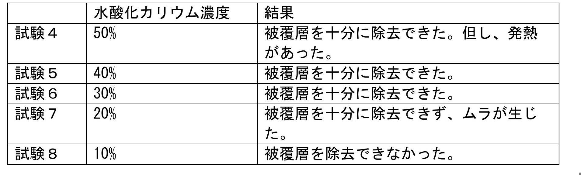
試験1と概ね同じ方法で被覆層を除去した。但し、水酸化カリウム溶液の濃度を変更した。結果は、以下の通りである。
以上の結果からすると、水酸化カリウムの濃度は、10%より大きく、50%未満であることが好ましく、25%以上40%以下であることが好ましい。
<1-3.他の溶液による除去>
試験1と概ね同じ方法で被覆層を除去した。但し、水酸化カリウム溶液の代わりに、試験9としてフッ化水素の水溶液(フッ化水素酸)を用い、試験10として水酸化ナトリウム水溶液を用いた。いずれも濃度を25%とし、40℃の環境下で24時間放置したところ、被覆層を十分に除去できた。
試験1と概ね同じ方法で被覆層を除去した。但し、水酸化カリウム溶液の代わりに、試験9としてフッ化水素の水溶液(フッ化水素酸)を用い、試験10として水酸化ナトリウム水溶液を用いた。いずれも濃度を25%とし、40℃の環境下で24時間放置したところ、被覆層を十分に除去できた。
<1-4.フッ化水素と水酸化カリウムとの組み合わせによる除去>
試験11:試験1と概ね同じ方法で被覆層を除去した。濃度が1%のフッ化水素の水溶液(フッ化水素酸)を含浸させた含浸材を用い、20℃の環境下で10分間放置した。その後、濃度が1%の水酸化カリウム水溶液を含浸させた含浸材を用い、室温で10分間放置した。その結果、被覆層を十分に除去できた。
試験11:試験1と概ね同じ方法で被覆層を除去した。濃度が1%のフッ化水素の水溶液(フッ化水素酸)を含浸させた含浸材を用い、20℃の環境下で10分間放置した。その後、濃度が1%の水酸化カリウム水溶液を含浸させた含浸材を用い、室温で10分間放置した。その結果、被覆層を十分に除去できた。
<2.レーザによる貫通孔の形成>
以下、レーザによる貫通孔の形成について説明する。まず、ガラス板に、被覆層を形成する。被覆層は3層により形成され、第1層が25nmの厚みのSi、第2層が25nmの厚みのSiO2、第3層が340nmの厚みのSiO2により形成されている。次に、ドットレーザを照射するレーザ装置(キーエンス株式会社製MD-X1520)により、被覆層を除去して貫通孔を形成した。そして、表4~表6に示すとおり、レーザの照射条件である、出力(Power)、周波数(Frequency)、移動速度(Speed)、幅(Width)、深さ(Depth)を変更した。また、ガラス板が露出した領域の抵抗(Resistance)を測定した。結果は、以下の通りである。

以下、レーザによる貫通孔の形成について説明する。まず、ガラス板に、被覆層を形成する。被覆層は3層により形成され、第1層が25nmの厚みのSi、第2層が25nmの厚みのSiO2、第3層が340nmの厚みのSiO2により形成されている。次に、ドットレーザを照射するレーザ装置(キーエンス株式会社製MD-X1520)により、被覆層を除去して貫通孔を形成した。そして、表4~表6に示すとおり、レーザの照射条件である、出力(Power)、周波数(Frequency)、移動速度(Speed)、幅(Width)、深さ(Depth)を変更した。また、ガラス板が露出した領域の抵抗(Resistance)を測定した。結果は、以下の通りである。
上記の各条件で試験を行った結果、グレーで着色した条件において、被覆層が十分に除去された。
1 ガラス板
2 被覆層
21 第1層
22 第2層
3 貫通孔(露出領域)
7 表示装置
8 カメラ(検出装置)
2 被覆層
21 第1層
22 第2層
3 貫通孔(露出領域)
7 表示装置
8 カメラ(検出装置)
Claims (39)
- 可視光反射率及び可視光透過率が20%以上である第1領域と、
前記第1領域よりも可視光透過率が高い第2領域と、
を有するガラス体。 - 前記第2領域の可視光透過率は、60%以上である、請求項1に記載のガラス体。
- 前記第2領域の面積が、10000mm2以下である、請求項1または2に記載のガラス体。
- 前記第1領域の可視光透過率が、前記第1領域の可視光反射率よりも低い、請求項1から3のいずれかに記載のガラス体。
- 前記第2領域が複数設けられている、請求項1から4のいずれかに記載のガラス体。
- 前記第2領域は、矩形状に形成されている、請求項1から4のいずれかに記載のガラス体。
- ガラス板と、
前記ガラス板の一方の面側に積層される被覆層と、
を備え、
前記被覆層は、無機酸化物によって形成され、前記ガラス板よりも高い屈性率を有し、
前記被複層には、前記ガラス板が露出する露出領域が形成されている、ガラス体。 - 前記被覆層は、屈折率が1.6以上の第1層を有している、請求項7に記載のガラス体。
- 前記第1層の膜厚が、3~50nmである、請求項8に記載のガラス体。
- 前記第1層上に積層され、前記第1層より屈折率の低い第2層をさらに備えている、請求項8または9に記載のガラス体。
- 前記第1層がSiを含有し、前記第2層がSiO2を含有している、請求項8から10のいずれかに記載のガラス体。
- 前記ガラス板と前記被覆層の間に、下地層が形成されている、請求項8から11のいずれかに記載のガラス体。
- 前記露出領域は、貫通孔または切り欠きによって形成されており、
前記貫通孔または切り欠きの縁部には凹凸が形成されている、請求項8から12のいずれかに記載のガラス体。 - 前記露出領域には、前記無機酸化物の一部が残存している、請求項8から13のいずれかに記載のガラス体。
- 前記被覆層において前記露出領域が形成されている箇所の内周面は、傾斜している、請求項7から14のいずれかに記載のガラス体。
- 前記ガラス板の露出領域の表面粗さは、当該露出領域の以外の領域の表面粗さと異なる、請求項7から15のいずれかに記載のガラス体。
- 前記第2領域の抵抗値が20MΩ以上である、請求項1から6のいずれかに記載のガラス体。
- 前記露出領域の抵抗値が20MΩ以上である、請求項7から14のいずれかに記載のガラス体。
- 前記第1領域に積層された遮蔽層をさらに備えている、請求項1から6のいずれかに記載のガラス体。
- 前記第2領域を囲むように前記第1領域が配置されている、請求項19に記載のガラス体。
- 前記第2領域が、前記第1領域よりも大きい、請求項19または20に記載のガラス体。
- 前記遮蔽層は、CIE規格の色度a*が-10~50,色度b*が-10~50,色度L*が10~100である、請求項19から21のいずれかに記載のガラス体。
- 前記ガラス板の他方の面側において、前記被覆層と対応する部分に積層される遮蔽層をさらに備えている、請求項7から16のいずれかに記載のガラス体。
- 前記露出領域を囲むように前記被覆層が配置されている、請求項23に記載のガラス体。
- 前記露出領域は、前記被覆層よりも大きい、請求項23または24に記載のガラス体。
- 前記遮蔽層は、CIE規格の色度a*が-10~50,色度b*が-10~50,色度L*が10~100である、請求項23から25のいずれかに記載のガラス体。
- 請求項1から14のいずれかに記載のガラス体と、
前記ガラス体を挟んで、前記ガラス板側に配置される表示装置と、
前記ガラス体を挟んで、前記ガラス板側に配置される検出装置と、
を備え、
前記検出装置は、前記露出領域を介して、前記ガラス体を挟んで、前記被覆層側に配置される物体の状態を検出するように構成されている、表示システム。 - 前記ガラス体の大きさは、1m2以上である、請求項27に記載の表示システム。
- ガラス板を準備する第1ステップと、
前記ガラス板の一方の面に、前記ガラス板よりも高い屈性率を有し、無機酸化物によって形成された被覆層を積層する第2ステップと、
前記無機酸化物と化学的に反応可能な反応溶液を前記被覆層の一部の箇所に、所定時間接触させることで、当該箇所を除去し、前記ガラス板が露出する露出領域を形成する第3ステップと、
を備えている、ガラス体の製造方法。 - 前記第3ステップに先立って、前記被覆層に、前記箇所が露出するようにマスク部材を配置するステップを、さらに備えている、請求項29に記載のガラス体の製造方法。
- 前記マスク部材は、基材と、当該基材を前記被覆層に固定するための粘着材と、を備え、
少なくとも前記粘着材は、前記反応溶液に対し耐久性を有している、請求項30に記載のガラス体の製造方法。 - 前記第3ステップにおいては、前記反応溶液が含浸された含浸材を、前記箇所に接触させる、請求項29から31のいずれかに記載のガラス体の製造方法。
- 前記含浸材は通気性を有する、請求項32に記載のガラス体の製造方法。
- 前記反応溶液は、少なくとも水酸化カリウムを含有する溶液である、請求項29から33のいずれかに記載のガラス体の製造方法。
- 前記反応溶液における前記水酸化カリウムの濃度は、10%より大きく、50%未満である、請求項34に記載のガラス体の製造方法。
- 前記第3ステップに先立って、前記箇所に、フッ化水素を接触させるステップをさらに備えている、請求項34または35に記載のガラス体の製造方法。
- ガラス板を準備する第1ステップと、
前記ガラス板の一方の面に、前記ガラス板よりも高い屈性率を有する被覆層を積層する第2ステップと、
前記被覆層の一部の箇所にドットレーザを照射することで、当該箇所を除去し、前記ガラス板が露出する露出領域を形成する第3ステップと、
を備えている、ガラス体の製造方法。 - 前記ドットレーザの出力は15W以上であり、50KHz以下の周期でドットが形成される、請求項37に記載のガラス体の製法方法。
- 前記ガラス板の面方向に、前記ドットレーザを100~900mm/sの速度で移動することで、前記箇所を除去する、請求項37または38のいずれかに記載のガラス体の製法方法。
Priority Applications (1)
| Application Number | Priority Date | Filing Date | Title |
|---|---|---|---|
| JP2021503653A JP7495391B2 (ja) | 2019-03-06 | 2020-03-05 | ガラス体 |
Applications Claiming Priority (2)
| Application Number | Priority Date | Filing Date | Title |
|---|---|---|---|
| JP2019041041 | 2019-03-06 | ||
| JP2019-041041 | 2019-03-06 |
Publications (1)
| Publication Number | Publication Date |
|---|---|
| WO2020179880A1 true WO2020179880A1 (ja) | 2020-09-10 |
Family
ID=72338195
Family Applications (1)
| Application Number | Title | Priority Date | Filing Date |
|---|---|---|---|
| PCT/JP2020/009499 Ceased WO2020179880A1 (ja) | 2019-03-06 | 2020-03-05 | ガラス体 |
Country Status (2)
| Country | Link |
|---|---|
| JP (1) | JP7495391B2 (ja) |
| WO (1) | WO2020179880A1 (ja) |
Citations (9)
| Publication number | Priority date | Publication date | Assignee | Title |
|---|---|---|---|---|
| JPS5244827A (en) * | 1975-10-07 | 1977-04-08 | Matsushita Electric Industrial Co Ltd | Method of producing diffusing plate for optical use |
| JPS57205341A (en) * | 1981-06-15 | 1982-12-16 | Seiko Epson Corp | Formation of glass photomask |
| JPS638238A (ja) * | 1986-06-25 | 1988-01-14 | Tokai Rika Co Ltd | 表示部を備えた鏡の製造方法 |
| JPS6424051A (en) * | 1987-07-16 | 1989-01-26 | Meisho Koki Kk | Sheet glass having transparency pattern and its production |
| JPH03125025U (ja) * | 1990-03-27 | 1991-12-18 | ||
| JPH08184706A (ja) * | 1994-12-28 | 1996-07-16 | Sony Corp | 光学素子の製造方法及び光学素子 |
| JP2003034554A (ja) * | 2001-05-11 | 2003-02-07 | Nippon Sheet Glass Co Ltd | 光学機器の設けられた車両用曲げガラス板 |
| JP2003313052A (ja) * | 2001-08-06 | 2003-11-06 | Nippon Sheet Glass Co Ltd | Hud用コンバイナー付き車両用ガラス板、およびその製造方法 |
| JP2016224077A (ja) * | 2015-05-26 | 2016-12-28 | 日本精機株式会社 | ヘッドアップディスプレイ装置 |
Family Cites Families (3)
| Publication number | Priority date | Publication date | Assignee | Title |
|---|---|---|---|---|
| JPH05116988A (ja) * | 1991-04-16 | 1993-05-14 | Nippon Soda Co Ltd | ハーフミラー用複合酸化物薄膜 |
| KR102058456B1 (ko) | 2015-08-31 | 2019-12-23 | 삼성전자주식회사 | 디스플레이 장치 및 이를 포함하는 가전기기 |
| JP2019015884A (ja) | 2017-07-07 | 2019-01-31 | フクビ化学工業株式会社 | ハーフミラー及びミラーディスプレイ |
-
2020
- 2020-03-05 JP JP2021503653A patent/JP7495391B2/ja active Active
- 2020-03-05 WO PCT/JP2020/009499 patent/WO2020179880A1/ja not_active Ceased
Patent Citations (9)
| Publication number | Priority date | Publication date | Assignee | Title |
|---|---|---|---|---|
| JPS5244827A (en) * | 1975-10-07 | 1977-04-08 | Matsushita Electric Industrial Co Ltd | Method of producing diffusing plate for optical use |
| JPS57205341A (en) * | 1981-06-15 | 1982-12-16 | Seiko Epson Corp | Formation of glass photomask |
| JPS638238A (ja) * | 1986-06-25 | 1988-01-14 | Tokai Rika Co Ltd | 表示部を備えた鏡の製造方法 |
| JPS6424051A (en) * | 1987-07-16 | 1989-01-26 | Meisho Koki Kk | Sheet glass having transparency pattern and its production |
| JPH03125025U (ja) * | 1990-03-27 | 1991-12-18 | ||
| JPH08184706A (ja) * | 1994-12-28 | 1996-07-16 | Sony Corp | 光学素子の製造方法及び光学素子 |
| JP2003034554A (ja) * | 2001-05-11 | 2003-02-07 | Nippon Sheet Glass Co Ltd | 光学機器の設けられた車両用曲げガラス板 |
| JP2003313052A (ja) * | 2001-08-06 | 2003-11-06 | Nippon Sheet Glass Co Ltd | Hud用コンバイナー付き車両用ガラス板、およびその製造方法 |
| JP2016224077A (ja) * | 2015-05-26 | 2016-12-28 | 日本精機株式会社 | ヘッドアップディスプレイ装置 |
Also Published As
| Publication number | Publication date |
|---|---|
| JP7495391B2 (ja) | 2024-06-04 |
| JPWO2020179880A1 (ja) | 2020-09-10 |
Similar Documents
| Publication | Publication Date | Title |
|---|---|---|
| JP6242902B2 (ja) | 太陽エネルギーシステムに適した着色反射および高日射透過率を有する積層グレージング(laminatedglazing) | |
| US9573842B2 (en) | Transparent glass substrate having antiglare surface | |
| JP5275442B2 (ja) | 発熱体およびその製造方法 | |
| CN115250617A (zh) | 具有复合玻璃板和p偏振辐射的投影装置 | |
| US20190285934A1 (en) | Transparent substrate having light blocking region and display device | |
| CN109073803A (zh) | 光学体、窗材料及卷帘 | |
| CN102165334A (zh) | 显示器用过滤器 | |
| JP2020109510A (ja) | レンズ及びその製造方法とレンズモジュール | |
| EP4663615A1 (en) | Glass laminate, display device, device, and method for producing glass laminate | |
| TWI278657B (en) | A mold for manufacturing a microlens substrate, a method of manufacturing microlens substrate, a microlens substrate, a transmission screen, and a rear projection | |
| US20120040140A1 (en) | Multi-layered article and method of fabricating the same | |
| JP2017107011A (ja) | 光学部材及びそれを用いた機器 | |
| US20230339043A1 (en) | Glass articles comprising selectively patterned opaque layers for light sensors and display systems comprising the same | |
| US11320730B2 (en) | Dark-coloured or black projection screen | |
| KR20180132704A (ko) | 광학체 및 유리재 | |
| JP2008538451A (ja) | 細い導電線を有する光学コーティング | |
| JP2020116741A (ja) | 機能層付き基体およびその製造方法 | |
| JP7495391B2 (ja) | ガラス体 | |
| JP2020126162A (ja) | 画像表示用導光板 | |
| KR101613085B1 (ko) | 양면 난반사 유리스크린 겸용 칠판 및 그 제조방법 | |
| JP2006140205A (ja) | 電磁波遮蔽材およびその製造方法、ならびにディスプレイ用フィルム | |
| US20030035939A1 (en) | Windowpane for head up display and method for manufacturing the same | |
| JP2008039960A (ja) | 積層フィルム | |
| TWI296335B (en) | Optical element with an opaque chrome coating having an aperture and method of making same | |
| CN110713348B (zh) | 电子设备和玻璃盖板的制备方法 |
Legal Events
| Date | Code | Title | Description |
|---|---|---|---|
| 121 | Ep: the epo has been informed by wipo that ep was designated in this application |
Ref document number: 20766746 Country of ref document: EP Kind code of ref document: A1 |
|
| ENP | Entry into the national phase |
Ref document number: 2021503653 Country of ref document: JP Kind code of ref document: A |
|
| NENP | Non-entry into the national phase |
Ref country code: DE |
|
| 122 | Ep: pct application non-entry in european phase |
Ref document number: 20766746 Country of ref document: EP Kind code of ref document: A1 |