WO2020179426A1 - 純水製造装置及び純水製造装置の運転方法 - Google Patents
純水製造装置及び純水製造装置の運転方法 Download PDFInfo
- Publication number
- WO2020179426A1 WO2020179426A1 PCT/JP2020/006169 JP2020006169W WO2020179426A1 WO 2020179426 A1 WO2020179426 A1 WO 2020179426A1 JP 2020006169 W JP2020006169 W JP 2020006169W WO 2020179426 A1 WO2020179426 A1 WO 2020179426A1
- Authority
- WO
- WIPO (PCT)
- Prior art keywords
- pure water
- water production
- water
- production apparatus
- subsystem
- Prior art date
- Legal status (The legal status is an assumption and is not a legal conclusion. Google has not performed a legal analysis and makes no representation as to the accuracy of the status listed.)
- Ceased
Links
Images


Classifications
-
- B—PERFORMING OPERATIONS; TRANSPORTING
- B01—PHYSICAL OR CHEMICAL PROCESSES OR APPARATUS IN GENERAL
- B01D—SEPARATION
- B01D19/00—Degasification of liquids
-
- B—PERFORMING OPERATIONS; TRANSPORTING
- B01—PHYSICAL OR CHEMICAL PROCESSES OR APPARATUS IN GENERAL
- B01D—SEPARATION
- B01D61/00—Processes of separation using semi-permeable membranes, e.g. dialysis, osmosis or ultrafiltration; Apparatus, accessories or auxiliary operations specially adapted therefor
-
- B—PERFORMING OPERATIONS; TRANSPORTING
- B01—PHYSICAL OR CHEMICAL PROCESSES OR APPARATUS IN GENERAL
- B01D—SEPARATION
- B01D61/00—Processes of separation using semi-permeable membranes, e.g. dialysis, osmosis or ultrafiltration; Apparatus, accessories or auxiliary operations specially adapted therefor
- B01D61/02—Reverse osmosis; Hyperfiltration ; Nanofiltration
-
- B—PERFORMING OPERATIONS; TRANSPORTING
- B01—PHYSICAL OR CHEMICAL PROCESSES OR APPARATUS IN GENERAL
- B01D—SEPARATION
- B01D61/00—Processes of separation using semi-permeable membranes, e.g. dialysis, osmosis or ultrafiltration; Apparatus, accessories or auxiliary operations specially adapted therefor
- B01D61/14—Ultrafiltration; Microfiltration
-
- B—PERFORMING OPERATIONS; TRANSPORTING
- B01—PHYSICAL OR CHEMICAL PROCESSES OR APPARATUS IN GENERAL
- B01D—SEPARATION
- B01D61/00—Processes of separation using semi-permeable membranes, e.g. dialysis, osmosis or ultrafiltration; Apparatus, accessories or auxiliary operations specially adapted therefor
- B01D61/42—Electrodialysis; Electro-osmosis ; Electro-ultrafiltration; Membrane capacitive deionization
- B01D61/44—Ion-selective electrodialysis
- B01D61/46—Apparatus therefor
- B01D61/48—Apparatus therefor having one or more compartments filled with ion-exchange material, e.g. electrodeionisation
-
- B—PERFORMING OPERATIONS; TRANSPORTING
- B01—PHYSICAL OR CHEMICAL PROCESSES OR APPARATUS IN GENERAL
- B01D—SEPARATION
- B01D61/00—Processes of separation using semi-permeable membranes, e.g. dialysis, osmosis or ultrafiltration; Apparatus, accessories or auxiliary operations specially adapted therefor
- B01D61/58—Multistep processes
-
- C—CHEMISTRY; METALLURGY
- C02—TREATMENT OF WATER, WASTE WATER, SEWAGE, OR SLUDGE
- C02F—TREATMENT OF WATER, WASTE WATER, SEWAGE, OR SLUDGE
- C02F1/00—Treatment of water, waste water, or sewage
- C02F1/30—Treatment of water, waste water, or sewage by irradiation
- C02F1/32—Treatment of water, waste water, or sewage by irradiation with ultraviolet light
-
- C—CHEMISTRY; METALLURGY
- C02—TREATMENT OF WATER, WASTE WATER, SEWAGE, OR SLUDGE
- C02F—TREATMENT OF WATER, WASTE WATER, SEWAGE, OR SLUDGE
- C02F1/00—Treatment of water, waste water, or sewage
- C02F1/42—Treatment of water, waste water, or sewage by ion-exchange
-
- C—CHEMISTRY; METALLURGY
- C02—TREATMENT OF WATER, WASTE WATER, SEWAGE, OR SLUDGE
- C02F—TREATMENT OF WATER, WASTE WATER, SEWAGE, OR SLUDGE
- C02F1/00—Treatment of water, waste water, or sewage
- C02F1/44—Treatment of water, waste water, or sewage by dialysis, osmosis or reverse osmosis
-
- C—CHEMISTRY; METALLURGY
- C02—TREATMENT OF WATER, WASTE WATER, SEWAGE, OR SLUDGE
- C02F—TREATMENT OF WATER, WASTE WATER, SEWAGE, OR SLUDGE
- C02F1/00—Treatment of water, waste water, or sewage
- C02F1/46—Treatment of water, waste water, or sewage by electrochemical methods
- C02F1/469—Treatment of water, waste water, or sewage by electrochemical methods by electrochemical separation, e.g. by electro-osmosis, electrodialysis, electrophoresis
Definitions
- the present invention relates to a pure water production apparatus and an operation method of the pure water production apparatus, and more particularly to a pure water production apparatus used as raw water of ultrapure water and an operation method of the pure water production apparatus.
- ultrapure water used in the field of electronics such as semiconductors should be treated with ultrapure water production equipment consisting of a pretreatment device, a primary pure water device, and a subsystem for processing the primary pure water. Manufactured by.
- such an ultrapure water production apparatus is composed of a pretreatment apparatus 22, a primary pure water apparatus 23, and a subsystem (secondary pure water apparatus) 24, and such an ultrapure water production apparatus 21. Then, raw water (industrial water, city water, well water, etc.) W is treated to produce ultrapure water W3.
- the roles of each device in FIG. 5 are as follows.
- the pretreatment device 22 having a coagulation, pressure flotation (precipitation), filtration (film filtration) device, etc. removes suspended solids and colloidal substances in the raw water W. Further, in this process, it is possible to remove high molecular weight organic substances and hydrophobic organic substances.
- the primary deionized water device 23 includes a tank 25 for pretreated water W1, a pump 26, an ultraviolet (UV) oxidation device 27, a regenerative ion exchange device (mixed bed type or four bed and five tower type) 28, and a membrane degassing device. It has 29 and.
- the primary pure water device 23 removes most of the electrolytes, fine particles, viable bacteria, etc. in the pretreated water W1 and decomposes organic substances.
- the subsystem 24 is an ultraviolet oxidizing device that processes a sub tank 31 that stores the primary pure water W2 produced by the primary pure water device 23 described above and a primary pure water W2 that is supplied from the sub tank 31 via a pump (not shown). It has 32, a platinum group metal catalyst resin tower 33, a membrane deaerator 34, a non-regenerative mixed bed ion exchange device 35, and an ultrafiltration (UF) membrane 36 as a membrane filtration device.
- UF ultrafiltration
- a trace amount of organic matter (TOC component) contained in the primary pure water W2 is oxidatively decomposed by ultraviolet rays by an ultraviolet oxidizing device 32, and hydrogen peroxide generated by the irradiation of the ultraviolet rays is converted into a platinum group metal catalyst resin tower.
- the dissolved gas such as DO (dissolved oxygen) mixed in is removed by the membrane type deaerator 34 in the subsequent stage.
- a non-regenerative mixed bed type ion exchange device 35 to remove residual carbonate ions, organic acids, anionic substances, and further metal ions and cationic substances by ion exchange.
- fine particles are removed by an ultrafiltration (UF) membrane 36 to obtain ultrapure water (secondary pure water) W3, which is supplied to the use point (POU) 37, and the unused ultrapure water is discharged from the sub tank 31.
- UF ultrafiltration
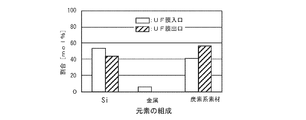
- the composition of the elements in the ultrapure water W3 at the inlet of the ultrafiltration (UF) membrane 36 includes silica, a metal, and a carbon-based material as shown in FIG.
- UF ultrafiltration
- the water quality required for the ultrapure water W3 is becoming severer, and it is necessary to reduce the fine particles of the ultrapure water (the outlet water of the ultrafiltration (UF) membrane 36). It is desired that the silica concentration in the primary pure water (pure water) W2 produced by the primary pure water device (pure water production device) is always kept low.
- the present invention has been made in view of the above problems, and an object of the present invention is to provide a pure water production apparatus for pure water and a method for operating the pure water production apparatus, which can always keep the silica concentration low.
- the present invention is a pure water production apparatus for producing pure water by sequentially treating water to be treated by a reverse osmosis membrane separating apparatus and an electrodeionization apparatus, wherein the electrodesorption device is used.
- a pure water production apparatus in which an ion apparatus is provided at the end of the pure water production apparatus (Invention 1).
- the silica component contained in pure water (primary pure water) supplied from the pure water producing apparatus is for the following reasons. That is, the silica adsorbed on the ion exchange resin polymerizes in the ion exchange resin as the accumulated amount increases, and it becomes difficult to remove it by the regeneration treatment of the ion exchange resin. For this reason, it accumulated in the ion exchange resin with the passage of time, and eventually the ion exchange resin broke through to cause leakage of silica. Therefore, an electrodeionizer is provided at the end of the pure water production apparatus, and the treated water of the reverse osmosis membrane separator is treated by the electrodeionizer.
- the desalting chamber of the electrodeionizer Even if the ion exchange resin inside adsorbs silica, it is ionized before the silica polymerizes, moves to the concentrated seed chamber and discharged, so that the ion exchange resin does not polymerize and accumulate, so pure water
- the silica concentration in it can always be kept low.
- the pure water production apparatus is a primary pure water apparatus of an ultrapure water production apparatus including a primary pure water apparatus and a subsystem (Invention 2).
- the subsystem has an ultraviolet oxidizing device, a membrane degassing device, an ion exchange device, and a membrane filtration device (Invention 3).
- the primary pure water (pure water) having a low silica concentration can be stably produced. Since it can be supplied to the subsystem, the load on the ion exchange device of the subsystem can be reduced, and the silica concentration and the number of fine particles of the ultrapure water treated by the membrane filtration device can be reduced.
- the present invention is a method for operating a pure water production apparatus in which a reverse osmosis membrane separation device and an electrodeionization device are provided in order, and the electrodeionization device is provided at the end, wherein the water to be treated
- the invention provides a method for operating a pure water production apparatus, in which pure water is produced by continuously passing water through a reverse osmosis membrane separator and an electric deionization apparatus (Invention 4).
- an electrodeionizer is provided at the end of the pure water production apparatus, and the treated water of the reverse osmosis membrane separator is treated by the electrodeionizer. Even if the ion exchange resin in the desalination chamber of the electrodeionizer adsorbs silica, it is ionized before the silica is polymerized and moved to the concentrated seed chamber and discharged, so that the ion exchange resin is polymerized and accumulated. Since there is no such thing, the silica concentration in pure water can always be kept low.
- the pure water producing apparatus is a primary pure water apparatus of an ultrapure water producing apparatus including a primary pure water apparatus and a subsystem, and the subsystem is an ultraviolet oxidizer and a membrane deionizer. It is preferable that an ultrapure water is produced by continuously supplying water to be treated to the primary deionized water device and the subsystem by including a gas device, an ion exchange device and a membrane type filtration device (invention 5).
- invention 5 by using it as a primary pure water device of an ultrapure water production device, primary pure water (pure water) having a low silica concentration can be stably supplied to the subsystem. It is possible to reduce the load on the ion exchange device of the subsystem and reduce the silica concentration and the number of fine particles in the ultrapure water treated by the membrane filtration device.
- the silica concentration of the ultrapure water obtained above can be set to 0.1 ⁇ g/L or less (Invention 6). Further, in the above inventions (Inventions 5 and 6), the number of fine particles of 50 nm or more in the obtained ultrapure water can be 100 / L or less (Invention 7).
- a pure water production device provided with a reverse osmosis membrane separation device and an electrodeionization device in this order and provided with the electrodeionization device at the end is used as primary pure water.
- the silica concentration can be reduced to 0.1 ⁇ g / L or less, and as a result, the number of fine particles of 50 nm or more is 100 / L or less. Can be manufactured stably.
- the electrodeionizer since the electrodeionizer is provided at the end of the pure water production apparatus, silica does not accumulate by treating the treated water of the reverse osmosis membrane separator with the electrodeionizer. , Pure water having a low silica concentration can be constantly produced.
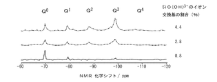
- FIG. 3 is an NMR chart showing the difference between the amount of silica adsorbed on the ion exchange resin and the structure of the adsorbed silica.
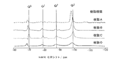
- 3 is an NMR chart showing the difference between the amount of silica adsorbed and the structure of adsorbed silica depending on the degree of crosslinking of the ion exchange resin.
- 6 is an NMR chart showing the difference between the amount of silica adsorbed on the ion exchange resin and the structure of the adsorbed silica before and after the regeneration of the ion exchange resin.
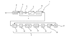
- FIG. 3 is a flow diagram showing an ultrapure water production system using the pure water production system according to one embodiment of the present invention. It is a flowchart which shows the ultrapure water production apparatus using the conventional pure water production apparatus. It is a graph which shows the composition of the element in the ultrapure water W at the inlet and the outlet of the ultrafiltration (UF) membrane in the ultrapure water production apparatus shown in FIG.
- UF ultrafiltration
- the present inventors have found the behavior of silica adsorbed on an ion exchange resin based on the characteristics of silica, and have reached it based on this.
- the characteristics of silica and the behavior of silica adsorbed on the ion exchange resin will be described below.
- Silica (SiO 2 ) includes silicon (Q 0 ), which is bonded to four hydroxyl groups, silicon (Q 1 ), which is bonded to three hydroxyl groups and one atom of neutral oxygen, and two silicon (Q 1 ), as shown in the following chemical formula group.
- silicas (SiO 2 ) move from Q 0 to Q 4 as the polymerization progresses.
- FIG. 1 shows the results of NMR analysis by the present inventors of the adsorption amount (concentration) of Si(OH) 3 ⁇ in the ion exchange resin and the abundances of five types of silica, Q 0 to Q 4 .
- the silica is found to be in accordance with adsorption to the ion exchange resin is increased, going up the peak intensity of silicon Q 3 structure.
- the ion exchange reaction in the ion exchange resin is an equilibrium reaction, it can be inferred that as the amount of polymerized silica in the ion exchange resin increases, the amount of polymerized silica leaking from the ion exchange resin increases due to the equilibrium reaction.
- the present inventors prepare four types of ion exchange resins having different degrees of cross-linking (ion exchange resins A, B, C, and D in order from the one having the highest degree of cross-linking of the ion exchange resins), and have a predetermined silica adsorption amount.
- the abundance ratios of the five kinds of silica, Q 0 to Q 4 , in the respective ion-exchange resins in Example 1 were analyzed by NMR. The results are shown in FIG. As is clear from FIG.
- silica has a broader peak of silica as the degree of cross-linking of the ion-exchange resin is lower, and therefore the polymer of silica is complicated, and if the ion-exchange resin is flexible, it is adsorbed. It can be seen that the polymerization proceeds between the parts that have been cross-linked.
- FIG. 4 is a flow chart showing an ultrapure water production system using the pure water production system according to an embodiment of the present invention.
- the ultrapure water production device 1 is composed of a pretreatment device 2, a primary pure water device 3 for pure water production, and a secondary pure water device (subsystem) 4.
- Ultrapure water W3 is produced by treating raw water (industrial water, city water, well water, etc.) W.
- the primary deionized water device 3 has a tank 5 for pretreated water W1, a pump 6, a reverse osmosis membrane (RO membrane) separation device 7 and an electric deionization device 8, and the electric deionization device 8 is arranged at the end thereof. It is characterized by the fact that it is.
- the subsystem 4 processes the same configuration as the subsystem 24 of the ultrapure water production apparatus 21 shown in FIG. 5, that is, the sub tank 31 and the primary pure water W2 supplied from the sub tank 31 via a pump (not shown). It has an ultraviolet oxidizing device 32, a platinum group metal catalyst resin tower 33, a film degassing device 34, a non-regenerative mixed bed ion exchange device 35, and an ultrafiltration (UF) membrane 36 as a film filtration device.
- UF ultrafiltration
- the raw water W is treated with a pretreatment system 2 having a coagulation, pressure flotation (precipitation), filtration (film filtration) device, etc. to remove suspended solids and colloidal substances in the raw water W and pretreated water. Get W1. Further, in this process, it is possible to remove high molecular weight organic substances and hydrophobic organic substances.
- the primary pure water device 3 removes most of the electrolytes, fine particles, etc. in the pretreated water W1 to produce the primary pure water (pure water) W2.
- the primary pure water device 3 of the present embodiment sequentially treats the pretreated water W1 by the reverse osmosis membrane (RO membrane) separation device 7 and the electrodeionization device 8, and is a non-regenerative ion exchange device. Does not have. Therefore, as described above, the silica contained in the treated water of the reverse osmosis membrane (RO membrane) separation device 7 does not undergo polymerization, and the electrodeionization device 8 repeatedly adsorbs and discharges the silica to the outside of the system. Therefore, primary pure water (pure water) W2 having a low silica concentration can be stably supplied.
- the primary pure water W2 is supplied to the subsystem 4, and the ultraviolet oxidizing device 32 oxidatively decomposes a trace amount of organic matter (TOC component) contained in the primary pure water W2 by ultraviolet rays, and is generated by irradiation with the ultraviolet rays.
- the ultraviolet rays are decomposed in the platinum group metal catalyst resin column 33, and the dissolved gas such as DO (dissolved oxygen) mixed in the film type degassing device 34 in the subsequent stage is removed.
- DO dissolved oxygen
- it is treated with a non-regenerative mixed bed type ion exchange device 35 to remove residual carbonate ions, organic acids, anionic substances, and further metal ions and cationic substances by ion exchange.
- the fine particles are removed by the ultrafiltration (UF) membrane 36 to obtain ultrapure water W3, which is supplied to the use point (POU) 37, and the unused ultrapure water is refluxed to the sub tank 31.
- UF ultrafiltration
- the primary pure water (pure water) W2 having a low silica concentration can be stably supplied to the subsystem 4, so that the sub system 4 can be supplied.
- the silica concentration of ultrapure water W3, which is the outlet water of the ultrafiltration (UF) membrane 36 can be reduced to 0.1 ⁇ g / L or less.
- the proportion of fine particles in the outlet water of the ultrafiltration (UF) membrane 36 is high due to silica, the number of fine particles is reduced, and the number of fine particles of 50 nm or more is 100. It is possible to stably supply ultrapure water W3 of / L or less.
- the pure water apparatus includes a reverse osmosis membrane separator and an electrodeionizer in order.
- the electric deionization device is provided at the end of the pure water producing device, various modifications can be made.
- the subsystem 4 may also be provided with a desalting means such as an RO membrane separator or an electric deionizer, and other various elements.
- a pure water producing apparatus may be further provided in the preceding stage of the primary pure water apparatus 3 so that the pure water producing apparatus has a three-stage configuration.
- the pure water production apparatus of the present invention is suitable as a primary pure water apparatus for an ultrapure water production apparatus, it does not have a subsystem 4 and is also used as a pure water production apparatus for simply producing pure water. You can
- Ultrapure water W3 was produced by using the ultrapure water producing apparatus 1 having the apparatus configuration shown in FIG. 1, and the silica concentration in the outlet water (ultrapure water W3) of the ultrafiltration (UF) membrane 36 was changed every one week. The measurement was performed 5 times, and the number of fine particles of 50 nm or more was measured with a fine particle meter (K Ramic KS Kurita Industry Co., Ltd. product name). The results are shown in Table 1.
- the subsystem 4 has the same configuration as that of the first embodiment, and constitutes an ultrapure water production system 21 as shown in FIG. 5 to produce ultrapure water W3, and the outlet water of the ultrafiltration (UF) membrane 36 (ultra pure water).
- UF ultrafiltration
- the silica concentration and the number of fine particles in water W3) were measured in the same manner. The results are also shown in Table 1.
- Example 1 a pure water production device (primary pure water device) 3 having a reverse osmosis membrane separation device 7 and an electrodeionization device 8 in order and an electrodeionization device 8 provided at the end is used.
- the silica concentration decreased from 0.08 ⁇ g / L to ⁇ 0.05 ⁇ g / L with time, and the number of fine particles of 50 nm or more was 100 / L or less.
- the silica concentration was 0.1 ⁇ g / L or more, and the number of fine particles of 50 nm or more was 500 / L or more.
- Ultrapure water production equipment Pretreatment equipment 3 Primary pure water equipment (pure water production equipment) 4 Secondary water purifier (subsystem) 5 Tank 6 Pump 7 Reverse Osmosis Membrane (RO Membrane) Separator 8 Electrodeionization Device 31 Sub-Tank 32 Ultraviolet Oxidation Device 33 Platinum Group Metal Catalyst Resin Tower 34 Membrane Deaeration Device 35 Non-Regenerative Mixed Bed Ion Exchange Device 36 Ultrafiltration (UF) Membrane W Raw water W1 Pretreated water W2 Primary pure water (pure water) W3 Ultra pure water (secondary pure water)
Landscapes
- Chemical & Material Sciences (AREA)
- Engineering & Computer Science (AREA)
- Water Supply & Treatment (AREA)
- Chemical Kinetics & Catalysis (AREA)
- Life Sciences & Earth Sciences (AREA)
- Organic Chemistry (AREA)
- Environmental & Geological Engineering (AREA)
- Hydrology & Water Resources (AREA)
- Health & Medical Sciences (AREA)
- General Chemical & Material Sciences (AREA)
- Electrochemistry (AREA)
- Molecular Biology (AREA)
- Analytical Chemistry (AREA)
- Urology & Nephrology (AREA)
- Nanotechnology (AREA)
- Toxicology (AREA)
- Separation Using Semi-Permeable Membranes (AREA)
- Treatment Of Water By Ion Exchange (AREA)
- Degasification And Air Bubble Elimination (AREA)
- Physical Water Treatments (AREA)
- Water Treatment By Electricity Or Magnetism (AREA)
Abstract
超純水製造装置1は、前処理装置2と純水製造としての一次純水装置3とサブシステム4との3段の装置で構成されていて、原水Wを処理することにより超純水W3が製造される。一次純水装置3は、前処理水W1のタンク5とポンプ6と逆浸透膜分離装置7と電気脱イオン装置8とを有し、末端が電気脱イオン装置8となっている。サブシステム4は、サブタンク31とこのサブタンク31から送給される一次純水W2を処理する紫外線酸化装置32と白金族金属触媒樹脂塔33と膜式脱気装置34と非再生型混床式イオン交換装置35と膜濾過装置としての限外濾過膜36とを有する。このような超純水製造装置によれば、シリカ濃度を常に低く保つことができる。
Description
本発明は純水製造装置及びこの純水製造装置の運転方法に関し、特に超純水の原水などとして用いられる純水製造装置及びこの純水製造装置の運転方法に関する。
従来、半導体等の電子産業分野で用いられている超純水は、前処理装置、一次純水装置及び一次純水を処理するサブシステムで構成される超純水製造装置で原水を処理することにより製造されている。
このような超純水製造装置は、図5に示すように前処理装置22、一次純水装置23及びサブシステム(二次純水装置)24から構成され、このような超純水製造装置21で、原水(工業用水、市水、井水等)Wを処理することにより超純水W3が製造される。図5において各装置の役割は次の通りである。
凝集、加圧浮上(沈殿)、濾過(膜濾過)装置などを有する前処理装置22では、原水W中の懸濁物質やコロイド物質の除去を行う。また、この過程では高分子系有機物、疎水性有機物などの除去も可能である。
一次純水装置23は、前処理水W1のタンク25とポンプ26と紫外線(UV)酸化装置27と再生型イオン交換装置(混床式又は4床5塔式など)28と膜式脱気装置29とを有する。この一次純水装置23で前処理水W1中の大半の電解質、微粒子、生菌等の除去を行うとともに有機物を分解する。
サブシステム24は、前述した一次純水装置23で製造された一次純水W2を貯留するサブタンク31とこのサブタンク31から図示しないポンプを介して送給される一次純水W2を処理する紫外線酸化装置32と白金族金属触媒樹脂塔33と膜式脱気装置34と非再生型混床式イオン交換装置35と膜濾過装置としての限外濾過(UF)膜36とを有する。このサブシステム24では、紫外線酸化装置32により一次純水W2中に含まれる微量の有機物(TOC成分)を紫外線により酸化分解し、この紫外線の照射により生じた過酸化水素を白金族金属触媒樹脂塔33で分解し、その後段の膜式脱気装置34で混入しているDO(溶存酸素)などの溶存ガスを除去する。続いて非再生型混床式イオン交換装置35で処理することで残留した炭酸イオン、有機酸類、アニオン性物質、さらには金属イオンやカチオン性物質をイオン交換によって除去する。そして、限外濾過(UF)膜36で微粒子を除去して超純水(二次純水)W3とし、これをユースポイント(POU)37に供給して、未使用の超純水はサブタンク31に還流する。
このような超純水製造装置21において、限外濾過(UF)膜36の入口における超純水W3中の元素の組成は、図6に示すようにシリカと金属と炭素系素材とが含まれているが、限外濾過(UF)膜36の出口においては、金属はほとんど除去され、シリカと炭素系素材が残存していることが知られている(非特許文献1)。
UPW Micro 2015 Tanaka et.Al.
しかしながら、近年、超純水W3に要求される水質は厳しくなる一途であり、超純水(限外濾過(UF)膜36の出口水)の微粒子を削減する必要があるが、そのためには、一次純水装置(純水製造装置)で製造される一次純水(純水)W2におけるシリカ濃度を常に低く保つことが望まれる。
本発明は上記課題に鑑みてなされたものであり、シリカ濃度を常に低く保つことが可能な純水の純水製造装置及びこの純水製造装置の運転方法を提供することを目的とする。
上記課題を解決するために第一に本発明は、被処理水を逆浸透膜分離装置と電気脱イオン装置とで順次処理して純水を製造する純水製造装置であって、前記電気脱イオン装置が純水製造装置の末端に設けられている、純水製造装置を提供する(発明1)。
かかる発明(発明1)によれば、純水製造装置から供給される純水(一次純水)中に含まれるシリカ成分を低減することができる。これは以下のような理由による。すなわち、イオン交換樹脂に吸着されたシリカは、その蓄積量が増加するに伴いイオン交換樹脂中において重合し、イオン交換樹脂の再生処理によっては除去しにくくなる。このため経時とともにイオン交換樹脂中に蓄積し、最終的にイオン交換樹脂が破過して、シリカが漏洩する原因となっていた。そこで、純水製造装置の末端に電気脱イオン装置を設けて、逆浸透膜分離装置の処理水を電気脱イオン装置で処理することにより、電気脱イオン装置では該電気脱イオン装置の脱塩室中のイオン交換樹脂がシリカを吸着しても、シリカが重合する前にイオン化して濃種室に移動して排出されるため、イオン交換樹脂が重合して蓄積することがないので、純水中のシリカ濃度を常に低く保つことができる。
上記発明(発明1)においては、前記純水製造装置が一次純水装置とサブシステムとを備える超純水製造装置の一次純水装置であることが好ましい(発明2)。特に上記発明(発明2)においては、前記サブシステムが紫外線酸化装置、膜式脱気装置、イオン交換装置及び膜式ろ過装置を有することが好ましい(発明3)。
かかる発明(発明2,3)によれば、超純水製造装置の一次純水装置として発明1に係る純水製造装置を用いることにより、シリカ濃度が低い一次純水(純水)を安定的にサブシステムに供給することができるので、サブシステムのイオン交換装置の負荷を低減し、膜式ろ過装置で処理した超純水のシリカ濃度及び微粒子数を低くすることができる。
また、第二に本発明は、逆浸透膜分離装置と電気脱イオン装置とを順に備え、該電気脱イオン装置が末端に設けられている純水製造装置の運転方法であって、被処理水を逆浸透膜分離装置及び電気脱イオン装置に連続して通水して純水を製造する、純水製造装置の運転方法を提供する(発明4)。
かかる発明(発明4)によれば、純水製造装置の末端に電気脱イオン装置を設けて、逆浸透膜分離装置の処理水を電気脱イオン装置で処理することにより、電気脱イオン装置では該電気脱イオン装置の脱塩室中のイオン交換樹脂がシリカを吸着しても、シリカが重合する前にイオン化して濃種室に移動して排出されるため、イオン交換樹脂が重合して蓄積することがないので、純水中のシリカ濃度を常に低く保つことができる。
上記発明(発明4)においては、前記純水製造装置が一次純水装置とサブシステムとを備える超純水製造装置の一次純水装置であり、前記サブシステムが、紫外線酸化装置、膜式脱気装置、イオン交換装置及び膜式ろ過装置を有し、被処理水を前記一次純水装置及び前記サブシステムに連続して通水して超純水を製造することが好ましい(発明5)。
かかる発明(発明5)によれば、超純水製造装置の一次純水装置として用いることにより、シリカ濃度が低い一次純水(純水)を安定的にサブシステムに供給することができるので、サブシステムのイオン交換装置の負荷を低減し、膜式ろ過装置で処理した超純水のシリカ濃度及び微粒子数を低くすることができる。
上記発明(発明5)においては、前記得られる超純水のシリカ濃度を0.1μg/L以下とすることができる(発明6)。また、上記発明(発明5,6)においては、前記得られる超純水の50nm以上の微粒子数を100個/L以下とすることができる(発明7)。
かかる発明(発明6,7)によれば、逆浸透膜分離装置と電気脱イオン装置とを順に備え、該電気脱イオン装置が末端に設けられている純水製造装置を一次純水として、これをサブシステムで処理して超純水を製造することにより、シリカ濃度が0.1μg/L以下にまで低減することができ、これにより50nm以上の微粒子数が100個/L以下の超純水を安定的に製造することができる。
本発明によれば、純水製造装置の末端に電気脱イオン装置を設けているので、逆浸透膜分離装置の処理水を電気脱イオン装置で処理することで、シリカが蓄積することがないため、シリカ濃度が低い純水を定常的に製造することができる。
本発明は、シリカの特性に基づくイオン交換樹脂に吸着したシリカの挙動を本発明者らが見出し、これに基づき到達したものである。以下、シリカの特性とイオン交換樹脂に吸着したシリカの挙動について説明する。
(シリカの特性)
シリカ(SiO2)には、下記化学式群に示すように4個の水酸基に結合したケイ素(Q0)、3個の水酸基と中性酸素1原子に結合したケイ素(Q1)、2個の水酸基と中性酸素2原子に結合したケイ素(Q2)、1個の水酸基と中性酸素3原子に結合したケイ素(Q3)及び中性酸素4原子に結合したケイ素(Q4)との5種類が存在する。これらのシリカ(SiO2)は、重合の進行とともにQ0からQ4へと移行していく。
シリカ(SiO2)には、下記化学式群に示すように4個の水酸基に結合したケイ素(Q0)、3個の水酸基と中性酸素1原子に結合したケイ素(Q1)、2個の水酸基と中性酸素2原子に結合したケイ素(Q2)、1個の水酸基と中性酸素3原子に結合したケイ素(Q3)及び中性酸素4原子に結合したケイ素(Q4)との5種類が存在する。これらのシリカ(SiO2)は、重合の進行とともにQ0からQ4へと移行していく。

(イオン交換樹脂のシリカの吸着量とシリカの構造)
まず、本発明者らがイオン交換樹脂におけるSi(OH)3 -の吸着量(濃度)と、Q0~Q4の5種類のシリカの存在量をNMRで解析した結果を図1に示す。図1から明らかなとおり、シリカはイオン交換樹脂への吸着量が増えるにしたがい、Q3構造のケイ素のピーク強度が上がっていることがわかる。このことから、イオン交換樹脂におけるイオン交換反応は平衡反応であるため、イオン交換樹脂中の重合したシリカが増えると、平衡反応によりイオン交換樹脂から漏洩してくる重合シリカが増えることが推測できる。
まず、本発明者らがイオン交換樹脂におけるSi(OH)3 -の吸着量(濃度)と、Q0~Q4の5種類のシリカの存在量をNMRで解析した結果を図1に示す。図1から明らかなとおり、シリカはイオン交換樹脂への吸着量が増えるにしたがい、Q3構造のケイ素のピーク強度が上がっていることがわかる。このことから、イオン交換樹脂におけるイオン交換反応は平衡反応であるため、イオン交換樹脂中の重合したシリカが増えると、平衡反応によりイオン交換樹脂から漏洩してくる重合シリカが増えることが推測できる。
(イオン交換樹脂の架橋度によるシリカの吸着量と構造)
次に本発明者らは、架橋度が異なる4種類のイオン交換樹脂(イオン交換樹脂の架橋度が高い方から順にイオン交換樹脂A、B、C、D)を用意し、所定のシリカ吸着量におけるそれぞれのイオン交換樹脂におけるQ0~Q4の5種類のシリカの存在割合をNMRで解析した。結果を図2に示す。図2から明らかなとおり、シリカはイオン交換樹脂の架橋度が低くなるほど、シリカのピークがブロード化していることから、シリカの重合体が複雑化しており、イオン交換樹脂に柔軟性があると吸着した部分同士で重合が進むことがわかる。
次に本発明者らは、架橋度が異なる4種類のイオン交換樹脂(イオン交換樹脂の架橋度が高い方から順にイオン交換樹脂A、B、C、D)を用意し、所定のシリカ吸着量におけるそれぞれのイオン交換樹脂におけるQ0~Q4の5種類のシリカの存在割合をNMRで解析した。結果を図2に示す。図2から明らかなとおり、シリカはイオン交換樹脂の架橋度が低くなるほど、シリカのピークがブロード化していることから、シリカの重合体が複雑化しており、イオン交換樹脂に柔軟性があると吸着した部分同士で重合が進むことがわかる。
(イオン交換樹脂の再生の前後によるシリカの吸着量と構造)
続いて本発明者らは、シリカを吸着したイオン交換樹脂を1%NaOH溶液で再生し、再生の前後によるイオン交換樹脂のシリカの吸着量と構造をNMRで解析した。結果を図3に示す。図3から明らかなとおり、NaOHによる再生により、Q0~Q2構造のシリカは、NaOHによる再生でイオン交換樹脂から容易に溶出するが、Q3構造のシリカはほとんど溶出しないことがわかる。
続いて本発明者らは、シリカを吸着したイオン交換樹脂を1%NaOH溶液で再生し、再生の前後によるイオン交換樹脂のシリカの吸着量と構造をNMRで解析した。結果を図3に示す。図3から明らかなとおり、NaOHによる再生により、Q0~Q2構造のシリカは、NaOHによる再生でイオン交換樹脂から容易に溶出するが、Q3構造のシリカはほとんど溶出しないことがわかる。
これらの結果から、イオン交換樹脂へのシリカの吸着量が増えると、Q3構造のシリカが増え、これは再生してもイオン交換樹脂に残存するので、シリカを溶出しやすくなることがわかる。したがって、吸着と系外への排出を繰り返す電気脱イオン装置であれば、シリカが重合せず排出されにくいといえる。
(純水製造装置及び超純水製造装置)
次に、上述したようなシリカの特性とイオン交換樹脂に吸着したシリカの挙動に基づく、本発明の一実施形態による純水製造装置及びこの純水製造装置を用いた超純製造装置について、図4を参照して詳細に説明する。
次に、上述したようなシリカの特性とイオン交換樹脂に吸着したシリカの挙動に基づく、本発明の一実施形態による純水製造装置及びこの純水製造装置を用いた超純製造装置について、図4を参照して詳細に説明する。
図4は本発明の一実施形態による純水製造装置を用いた超純水製造装置を示すフロー図である。図4において、超純水製造装置1は、前処理装置2と純水製造としての一次純水装置3と二次純水装置(サブシステム)4との3段の装置で構成されていて、原水(工業用水、市水、井水等)Wを処理することにより超純水W3が製造される。
一次純水装置3は、前処理水W1のタンク5とポンプ6と逆浸透膜(RO膜)分離装置7と電気脱イオン装置8とを有し、その末端に電気脱イオン装置8が配置されている点に特徴を有する。
サブシステム4は、前述した図5に示す超純水製造装置21のサブシステム24と同じ構成、すなわちサブタンク31とこのサブタンク31から図示しないポンプを介して送給される一次純水W2を処理する紫外線酸化装置32と白金族金属触媒樹脂塔33と膜式脱気装置34と非再生型混床式イオン交換装置35と膜濾過装置としての限外濾過(UF)膜36とを有する。
(純水製造装置の運転方法及び超純水製造装置の運転方法)
前述したような構成を有する純水製造装置を備えた超純水製造装置の運転方法について説明する。
前述したような構成を有する純水製造装置を備えた超純水製造装置の運転方法について説明する。
まず、原水Wを凝集、加圧浮上(沈殿)、濾過(膜濾過)装置などを有する前処理システム2で処理することにより、原水W中の懸濁物質やコロイド物質を除去して前処理水W1を得る。また、この過程では高分子系有機物、疎水性有機物などの除去も可能である。
次に、一次純水装置3は、前処理水W1中の大半の電解質、微粒子等を除去して一次純水(純水)W2を製造する。このとき本実施形態の一次純水装置3は、前処理水W1を逆浸透膜(RO膜)分離装置7と電気脱イオン装置8とで順次処理するものであり、非再生式のイオン交換装置を有しない。このため、前述したとおり、逆浸透膜(RO膜)分離装置7の処理水中に含まれるシリカは重合が進行することがなく、電気脱イオン装置8において吸着と系外への排出が繰り返し行われるので、シリカ濃度が低い一次純水(純水)W2を安定的に供給することができる。
そして、この一次純水W2は、サブシステム4に供給されて、紫外線酸化装置32により一次純水W2中に含まれる微量の有機物(TOC成分)を紫外線により酸化分解し、この紫外線の照射により生じた過酸化水素を白金族金属触媒樹脂塔33で分解し、その後段の膜式脱気装置34で混入しているDO(溶存酸素)などの溶存ガスを除去する。続いて非再生型混床式イオン交換装置35で処理することで残留した炭酸イオン、有機酸類、アニオン性物質、さらには金属イオンやカチオン性物質をイオン交換によって除去する。そして、限外濾過(UF)膜36で微粒子を除去して超純水W3とし、これをユースポイント(POU)37に供給して、未使用の超純水はサブタンク31に還流する。
上述したような超純水W3を製造する超純水製造装置1の運転方法において、シリカ濃度が低い一次純水(純水)W2をサブシステム4に安定的に供給することができるので、サブシステム4を適切な構成として運転することにより、限外濾過(UF)膜36の出口水である超純水W3のシリカ濃度を0.1μg/L以下とすることができる。この結果、図6に示すように限外濾過(UF)膜36の出口水中の微粒子はシリカに起因する割合が高いので、微粒子数が減少することになり、もって50nm以上の微粒子数が100個/L以下の超純水W3を安定的に供給することが可能となる。
以上、本発明の一実施形態について添付図面を参照して説明してきたが、本発明は前記実施形態に限定されず、純水装置が逆浸透膜分離装置と電気脱イオン装置とを順に備え、かつ電気脱イオン装置が純水製造装置の末端に設けられていれば、種々の変形実施が可能である。例えば、サブシステム4にもRO膜分離装置や電気脱イオン装置等の脱塩手段や他の各種エレメントを設けてもよい。また、一次純水装置3の前段にさらに純水製造装置を設けて純水製造装置を3段構成としてもよい。さらに、本発明の純水製造装置は、超純水製造装置の一次純水装置として好適なものであるが、サブシステム4を備えず、単に純水を製造する純水製造装置としても用いることができる。
以下、実施例及び比較例を挙げて本発明をより具体的に説明するが、本発明は下記の実施例に限定されるものではない。
[実施例1]
図1に示す装置構成の超純水製造装置1を用いて超純水W3を製造し、限外濾過(UF)膜36の出口水(超純水W3)中のシリカ濃度を1週間ごとに5回計測するとともに、50nm以上の微粒子数を微粒子計(KラミックKS 栗田工業(株)製品名)により測定した。結果を表1に示す。
図1に示す装置構成の超純水製造装置1を用いて超純水W3を製造し、限外濾過(UF)膜36の出口水(超純水W3)中のシリカ濃度を1週間ごとに5回計測するとともに、50nm以上の微粒子数を微粒子計(KラミックKS 栗田工業(株)製品名)により測定した。結果を表1に示す。
[比較例1]
サブシステム4は実施例1と同じ構成として、図5に示すように超純水製造装置21を構成し、超純水W3を製造し、限外濾過(UF)膜36の出口水(超純水W3)中のシリカ濃度及び微粒数を同様に測定した。結果を表1にあわせて示す。
サブシステム4は実施例1と同じ構成として、図5に示すように超純水製造装置21を構成し、超純水W3を製造し、限外濾過(UF)膜36の出口水(超純水W3)中のシリカ濃度及び微粒数を同様に測定した。結果を表1にあわせて示す。

表1から明らかな通り、逆浸透膜分離装置7と電気脱イオン装置8とを順に備え、かつ電気脱イオン装置8が末端に設けられている純水製造装置(一次純水装置)3を用いた実施例1では、シリカ濃度が0.08μg/Lから経時とともに低下して<0.05μg/Lとなり、50nm以上の微粒子数も100個/L以下であった。これに対し一次純水装置に再生式イオン交換装置を用いた比較例1では、シリカ濃度が0.1μg/L以上であり、50nm以上の微粒子数も500個/L以上であった。
1 超純水製造装置
2 前処理装置
3 一次純水装置(純水製造装置)
4 二次純水装置(サブシステム)
5 タンク
6 ポンプ
7 逆浸透膜(RO膜)分離装置
8 電気脱イオン装置
31 サブタンク
32 紫外線酸化装置
33 白金族金属触媒樹脂塔
34 膜式脱気装置
35 非再生型混床式イオン交換装置
36 限外濾過(UF)膜
W 原水
W1 前処理水
W2 一次純水(純水)
W3 超純水(二次純水)
2 前処理装置
3 一次純水装置(純水製造装置)
4 二次純水装置(サブシステム)
5 タンク
6 ポンプ
7 逆浸透膜(RO膜)分離装置
8 電気脱イオン装置
31 サブタンク
32 紫外線酸化装置
33 白金族金属触媒樹脂塔
34 膜式脱気装置
35 非再生型混床式イオン交換装置
36 限外濾過(UF)膜
W 原水
W1 前処理水
W2 一次純水(純水)
W3 超純水(二次純水)
Claims (7)
- 被処理水を逆浸透膜分離装置と電気脱イオン装置とで順次処理して純水を製造する純水製造装置であって、
前記電気脱イオン装置が純水製造装置の末端に設けられている、純水製造装置。 - 前記純水製造装置が一次純水装置とサブシステムとを備える超純水製造装置の一次純水装置である、請求項1に記載の純水製造装置。
- 前記サブシステムが紫外線酸化装置、膜式脱気装置、イオン交換装置及び膜式ろ過装置を有する、請求項2に記載の純水製造装置。
- 逆浸透膜分離装置と電気脱イオン装置とを順に備え、該電気脱イオン装置が末端に設けられている純水製造装置の運転方法であって、被処理水を逆浸透膜分離装置及び電気脱イオン装置に連続して通水して純水を製造する、純水製造装置の運転方法。
- 前記純水製造装置が一次純水装置とサブシステムとを備える超純水製造装置の一次純水装置であり、前記サブシステムが、紫外線酸化装置、膜式脱気装置、イオン交換装置及び膜式ろ過装置を有し、被処理水を前記一次純水装置及び前記サブシステムに連続して通水して超純水を製造する、請求項4に記載の純水製造装置の運転方法。
- 前記得られる超純水のシリカ濃度が0.1μg/L以下である、請求項5に記載の純水製造装置の運転方法。
- 前記得られる超純水の50nm以上の微粒子数が100個/L以下である、請求項5又は6に記載の純水製造装置の運転方法。
Applications Claiming Priority (2)
| Application Number | Priority Date | Filing Date | Title |
|---|---|---|---|
| JP2019039982A JP2020142178A (ja) | 2019-03-05 | 2019-03-05 | 超純水製造装置及び超純水製造装置の運転方法 |
| JP2019-039982 | 2019-03-05 |
Publications (1)
| Publication Number | Publication Date |
|---|---|
| WO2020179426A1 true WO2020179426A1 (ja) | 2020-09-10 |
Family
ID=72338378
Family Applications (1)
| Application Number | Title | Priority Date | Filing Date |
|---|---|---|---|
| PCT/JP2020/006169 Ceased WO2020179426A1 (ja) | 2019-03-05 | 2020-02-18 | 純水製造装置及び純水製造装置の運転方法 |
Country Status (3)
| Country | Link |
|---|---|
| JP (1) | JP2020142178A (ja) |
| TW (1) | TW202100227A (ja) |
| WO (1) | WO2020179426A1 (ja) |
Cited By (1)
| Publication number | Priority date | Publication date | Assignee | Title |
|---|---|---|---|---|
| JPWO2024014218A1 (ja) * | 2022-07-14 | 2024-01-18 |
Families Citing this family (1)
| Publication number | Priority date | Publication date | Assignee | Title |
|---|---|---|---|---|
| EP4534187A1 (en) * | 2022-06-03 | 2025-04-09 | Toray Industries, Inc. | Composite semipermeable membrane and method for producing same |
Citations (5)
| Publication number | Priority date | Publication date | Assignee | Title |
|---|---|---|---|---|
| JPH0957271A (ja) * | 1995-08-22 | 1997-03-04 | Japan Organo Co Ltd | 電気脱イオン法による被処理水の処理方法及びその方法に使用する装置 |
| JP2010172806A (ja) * | 2009-01-28 | 2010-08-12 | Miura Co Ltd | 純水製造システム |
| JP2017131846A (ja) * | 2016-01-28 | 2017-08-03 | 栗田工業株式会社 | 超純水製造装置および超純水製造装置の運転方法 |
| JP2018089587A (ja) * | 2016-12-05 | 2018-06-14 | 栗田工業株式会社 | 超純水製造装置及び超純水製造装置の運転方法 |
| JP2018094531A (ja) * | 2016-12-16 | 2018-06-21 | 栗田工業株式会社 | 超純水製造装置及び超純水製造装置の運転方法 |
Family Cites Families (2)
| Publication number | Priority date | Publication date | Assignee | Title |
|---|---|---|---|---|
| JP6228531B2 (ja) * | 2014-12-19 | 2017-11-08 | 栗田工業株式会社 | 超純水製造装置及び超純水製造方法 |
| JP6778591B2 (ja) * | 2016-11-25 | 2020-11-04 | 野村マイクロ・サイエンス株式会社 | 超純水製造方法及び超純水製造システム |
-
2019
- 2019-03-05 JP JP2019039982A patent/JP2020142178A/ja active Pending
-
2020
- 2020-02-18 TW TW109105210A patent/TW202100227A/zh unknown
- 2020-02-18 WO PCT/JP2020/006169 patent/WO2020179426A1/ja not_active Ceased
Patent Citations (5)
| Publication number | Priority date | Publication date | Assignee | Title |
|---|---|---|---|---|
| JPH0957271A (ja) * | 1995-08-22 | 1997-03-04 | Japan Organo Co Ltd | 電気脱イオン法による被処理水の処理方法及びその方法に使用する装置 |
| JP2010172806A (ja) * | 2009-01-28 | 2010-08-12 | Miura Co Ltd | 純水製造システム |
| JP2017131846A (ja) * | 2016-01-28 | 2017-08-03 | 栗田工業株式会社 | 超純水製造装置および超純水製造装置の運転方法 |
| JP2018089587A (ja) * | 2016-12-05 | 2018-06-14 | 栗田工業株式会社 | 超純水製造装置及び超純水製造装置の運転方法 |
| JP2018094531A (ja) * | 2016-12-16 | 2018-06-21 | 栗田工業株式会社 | 超純水製造装置及び超純水製造装置の運転方法 |
Cited By (3)
| Publication number | Priority date | Publication date | Assignee | Title |
|---|---|---|---|---|
| JPWO2024014218A1 (ja) * | 2022-07-14 | 2024-01-18 | ||
| WO2024014218A1 (ja) * | 2022-07-14 | 2024-01-18 | 栗田工業株式会社 | 超純水製造装置及び超純水製造装置の運転方法 |
| JP7513213B2 (ja) | 2022-07-14 | 2024-07-09 | 栗田工業株式会社 | 超純水製造装置及び超純水製造装置の運転方法 |
Also Published As
| Publication number | Publication date |
|---|---|
| JP2020142178A (ja) | 2020-09-10 |
| TW202100227A (zh) | 2021-01-01 |
Similar Documents
| Publication | Publication Date | Title |
|---|---|---|
| CN101827792B (zh) | 纯水制造装置及纯水制造方法 | |
| TWI754042B (zh) | 超純水製造系統及超純水製造方法 | |
| KR102259712B1 (ko) | 전기 탈이온 장치 및 순수 제조 장치 | |
| JP6728876B2 (ja) | 電気脱イオン装置及び脱イオン水の製造方法 | |
| JP7289206B2 (ja) | ホウ素除去装置及びホウ素除去方法、並びに、純水製造装置及び純水の製造方法 | |
| JP6634918B2 (ja) | 超純水製造システム | |
| KR20170097036A (ko) | 초순수 제조 장치 및 초순수 제조 방법 | |
| WO2015012054A1 (ja) | ホウ素含有水の処理方法及び装置 | |
| JP2011194402A (ja) | 超純水製造装置 | |
| WO2018096700A1 (ja) | 超純水製造システム及び超純水製造方法 | |
| CN115551809B (zh) | 硼去除装置及方法、纯水制造装置以及纯水制造方法 | |
| JP6228471B2 (ja) | 被処理水の処理装置、純水の製造装置および被処理水の処理方法 | |
| WO2023149415A1 (ja) | 純水製造装置及び純水製造装置の運転方法 | |
| CN112424128A (zh) | 纯水制造系统及纯水制造方法 | |
| WO2020179426A1 (ja) | 純水製造装置及び純水製造装置の運転方法 | |
| JP4635827B2 (ja) | 超純水製造方法および装置 | |
| JPH10309588A (ja) | 水処理方法、水処理装置及び純水製造装置 | |
| JP7305960B2 (ja) | 超純水製造装置の運転方法 | |
| JP7183208B2 (ja) | 超純水製造装置及び超純水製造方法 | |
| JP2020116507A (ja) | ホウ素超高純度除去型超純水製造装置及びホウ素超高純度除去超純水の製造方法 | |
| JPH0747364A (ja) | 超純水製造装置 | |
| JPH10216749A (ja) | 超純水製造装置 | |
| JPH1128482A (ja) | 純水製造方法 | |
| JP3727156B2 (ja) | 脱塩装置 | |
| JP7383141B2 (ja) | Toc除去装置及びtoc除去方法 |
Legal Events
| Date | Code | Title | Description |
|---|---|---|---|
| 121 | Ep: the epo has been informed by wipo that ep was designated in this application |
Ref document number: 20766709 Country of ref document: EP Kind code of ref document: A1 |
|
| NENP | Non-entry into the national phase |
Ref country code: DE |
|
| 122 | Ep: pct application non-entry in european phase |
Ref document number: 20766709 Country of ref document: EP Kind code of ref document: A1 |