WO2020179306A1 - マスク及びマスクの製造方法 - Google Patents
マスク及びマスクの製造方法 Download PDFInfo
- Publication number
- WO2020179306A1 WO2020179306A1 PCT/JP2020/003677 JP2020003677W WO2020179306A1 WO 2020179306 A1 WO2020179306 A1 WO 2020179306A1 JP 2020003677 W JP2020003677 W JP 2020003677W WO 2020179306 A1 WO2020179306 A1 WO 2020179306A1
- Authority
- WO
- WIPO (PCT)
- Prior art keywords
- mask
- elastic member
- sheet material
- wearer
- sheet
- Prior art date
- Legal status (The legal status is an assumption and is not a legal conclusion. Google has not performed a legal analysis and makes no representation as to the accuracy of the status listed.)
- Ceased
Links
Images







Classifications
-
- A—HUMAN NECESSITIES
- A41—WEARING APPAREL
- A41D—OUTERWEAR; PROTECTIVE GARMENTS; ACCESSORIES
- A41D13/00—Professional, industrial or sporting protective garments, e.g. surgeons' gowns or garments protecting against blows or punches
- A41D13/05—Professional, industrial or sporting protective garments, e.g. surgeons' gowns or garments protecting against blows or punches protecting only a particular body part
- A41D13/11—Protective face masks, e.g. for surgical use, or for use in foul atmospheres
-
- A—HUMAN NECESSITIES
- A62—LIFE-SAVING; FIRE-FIGHTING
- A62B—DEVICES, APPARATUS OR METHODS FOR LIFE-SAVING
- A62B18/00—Breathing masks or helmets, e.g. affording protection against chemical agents or for use at high altitudes or incorporating a pump or compressor for reducing the inhalation effort
- A62B18/02—Masks
Definitions
- the present invention relates to a mask and a method for manufacturing the mask.
- a mask used for sickness flying dust such as pollen or yellow sand, and other daily life
- a mask with pleats formed on the main body of the mask which can be expanded vertically when worn.
- the mask body By wearing such a mask with the pleats spread up and down, the mask body has a mountain-shaped three-dimensional shape, and a space is formed around the wearer's nose and mouth, making it easier for the wearer to breathe.
- a sheet material having a length of a plurality of mask main body portions in the left-right direction is flowed in the longitudinal direction, and pleats are formed in parallel with the longitudinal direction.
- the sheet material is formed into a mask main body by cutting the sheet material to a predetermined length at a cut perpendicular to the formed pleats, and further, after rotating the formed mask main body by 90°,
- a manufacturing method is known in which a rubber cord forming an ear hook is attached to the vicinity of both left and right ends of the mask body (see, for example, Patent Document 2).
- the formed mask main body portion is left in a state where the mask main body portion is formed by cutting the sheet material on which the pleats are formed. Since the left and right ends of the mask are arranged so as to be in contact with each other, it is difficult to form an ear hook by attaching rubber cords to the vicinity of the left and right ends of the mask body as it is. Therefore, since the step of rotating the formed mask body portion by 90° is essential, the mask cannot be manufactured in a series of steps while flowing the sheet material forming the mask body portion in a certain direction, It was difficult to improve manufacturing efficiency.
- An object of the present invention is to provide a mask and a mask manufacturing method capable of improving manufacturing efficiency.
- the invention according to claim 1 is A mask comprising a mask main body formed of a sheet material, which covers a target site on the wearer's face, and a pair of left and right ear hooks for locking the mask main body to the wearer's ears, ,
- the mask body is With multiple pleats that can be expanded vertically
- An elastic member formed of a material having elasticity and provided in the vicinity of each of the left and right ends of the mask main body so as to extend in the vertical direction, Equipped with The elastic member is connected to the sheet material forming the mask main body portion at a plurality of connecting portions formed at predetermined intervals in the vertical direction, and the pleats are positioned at a position between the connecting portions in the vertical direction. It is characterized by being formed. According to the present invention, it is possible to provide a mask capable of improving manufacturing efficiency.
- the invention according to claim 2 is the mask according to claim 1,
- the mask body is The outer end side sheet material arranged on the forefront, the right end folded back portion that is folded back to the rear side so as to wrap around the right end portion,
- the elastic member is Between the wearer side sheet material arranged on the rearmost surface and the right end folded portion, Between the wearer side sheet material and the left end folded portion, It is equipped with. According to the present invention, it is possible to provide a mask capable of improving manufacturing efficiency while suppressing deterioration of wearing comfort.
- the invention described in claim 3 is the mask according to claim 1, In the vicinity of the left and right ends of the surface on the wearer side, a gather sheet formed to stand upright from the surface is provided, The elastic member is provided on the gather sheet. According to the present invention, it is possible to provide a mask capable of improving the manufacturing efficiency while improving the hermeticity of the left and right sides of the mask.
- the invention according to claim 4 is the mask according to claim 3,
- the gather sheet includes a first surface portion connected to a wearer-side sheet material arranged on a rearmost surface of the mask body portion, a second surface portion connected to an end portion of the first surface portion, and the second surface portion.
- a third surface portion connected to an end portion on the opposite side to the first surface portion of The elastic member is provided between the second surface portion and the third surface portion.
- a fifth aspect of the present invention in a mask manufacturing method, Along the vertical direction of the mask body in the longitudinal direction, in the vicinity of both ends in the lateral direction of the sheet material having a length of a plurality of sheets, elastic members formed of an elastic material An elastic member attaching step of connecting at a connecting portion formed with a predetermined interval in a state of being stretched to An ear hook portion forming step of forming an ear hook portion on the sheet material; A cutting step of cutting the sheet material to the width in the vertical direction of the mask body, and It is characterized by including. According to the present invention, it is possible to provide a method for manufacturing a mask that can improve the manufacturing efficiency.
- the invention according to claim 6 is the method for manufacturing a mask according to claim 5. It is characterized by including a laminating step of laminating a plurality of the sheet materials. According to the present invention, it is possible to provide a method for manufacturing a mask that can improve the manufacturing efficiency.
- a sheet material that is longer than the other sheet materials in the lateral direction is used as the outer surface side sheet material located on the foremost surface of the mask main body, and both ends of the outer surface side sheet material in the lateral direction are exposed.
- the exposed portion is folded back to the rear surface side of the mask main body, and further includes a folded-back portion forming step of forming a right end folded portion and a left end folded portion,
- a folded-back portion forming step of forming a right end folded portion and a left end folded portion
- the elastic member attaching step Between the right end folded portion and the wearer side sheet material arranged on the rearmost surface, Between the left end folded portion and the wearer-side sheet material, It is characterized in that the elastic member is attached so that the elastic member is arranged.
- the invention according to claim 8 is the method for manufacturing a mask according to claim 5 or 6,
- the mask main body of the sheet material includes a gather sheet attaching step of attaching the gathered sheet so as to stand up from the sheet material in the vicinity of both ends in the lateral direction of the surface facing the wearer.
- the elastic member attaching step By connecting the elastic member to the gathered sheet in a state of being attached to the sheet material or in a state before being attached to the gathering sheet at a connecting portion formed with a predetermined gap, the sheet is passed through the gathering sheet.
- the elastic member is attached to the material. According to the present invention, it is possible to provide a mask manufacturing method capable of improving the manufacturing efficiency while improving the hermeticity of the left and right sides of the mask.
- the invention according to claim 9 is the method for manufacturing a mask according to claim 8.
- the elastic member is attached so as to be sandwiched between the gather sheets.
- ADVANTAGE OF THE INVENTION According to this invention, the manufacturing method of the mask which can improve the manufacturing efficiency can be provided, suppressing the deterioration of the mounting feeling of the manufactured mask.
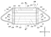
- the mask 100 includes a mask main body 1 that covers the nose, mouth, chin, etc. of the wearer's face, and a right for hooking the mask main body 1 on the right ear of the wearer.
- An ear hook 2 and a left ear hook 3 for hooking the mask body 1 on the wearer's left ear are provided.
- the mask 100 is worn with the rear surface side of the mask body 1 facing the wearer's face.
- the mask body 1 is formed of a plurality of sheet materials into a substantially rectangular shape in a front view.
- the mask body 1 is formed to have a width of preferably 120 mm to 210 mm, further preferably 145 mm to 175 mm, and a vertical direction of preferably 70 mm to 100 mm, more preferably 80 mm to 90 mm.
- the mask main body 1 is located on the outermost front surface (the surface farthest from the wearer's skin) of the mask main body 1 in order from the surface farthest from the wearer's skin.
- the filter 1b, and the wearer-side non-woven fabric 1c located on the rearmost surface of the mask body 1 (the surface closest to the wearer's skin).
- the left and right ends of the mask body 1 are folded back to the rear side so that the outer nonwoven fabric 1a goes around the left and right of the mask, and the right end folded portion 13 and the left end are folded.
- the folded portion 14 is formed.
- the right end folded portion 13 and the left end folded portion 14 preferably have a width of 5 mm to 20 mm in the left-right direction.
- polypropylene spunbond, polyethylene spunbond, nylon spunbond, etc. are used as the outer surface side nonwoven fabric 1a and the wearer side nonwoven fabric 1c, and polypropylene meltblown, rayon spunbond, etc. are used as the filter 1b.
- a moisturizer, a softening agent, an antibacterial agent, etc. is also possible to apply to the wearer-side nonwoven fabric 1c.
- polypropylene spunbond is used as the outer surface side nonwoven fabric 1a
- nylon spunbond coated with a moisturizer is used as the wearer side nonwoven fabric 1c
- polypropylene meltblown is used as the filter 1b sandwiched between them.
- the configuration of the mask main body 1 is not limited to the above, and more sheet materials may be laminated, or may be formed from a smaller number of sheet materials than three.
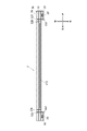
- the outer surface side non-woven fabric 1a, the filter 1b and the wearer side non-woven fabric 1c are overlapped and folded as shown in FIG. 3, so that the front side, as shown in FIG. 1 to FIG.
- Four pleats first pleats 111, second pleats 112, third pleats 113, and fourth pleats 114 from the top
- the mask main body 1 can be expanded in the vertical direction by unfolding these pleats in the vertical direction.
- the specific number and arrangement of pleats are not limited to this, and more or more than this. A small number of pleats may be formed. Also, the arrangement interval can be changed appropriately.
- the outer surface side non-woven fabric 1a, the filter 1b, and the wearer side non-woven fabric 1c forming the mask main body 1 are welded back and forth by heat, ultrasonic waves, or the like in the vicinity of the upper and lower and left and right ends, and FIGS. 2, an upper end joint 121 is formed near the upper end, and a lower end joint 122 is formed near the lower end. As shown in FIGS. 1, 2 and 4, the right end joint 123 is near the right end. A left end joint 124 is formed near the left end.
- the upper end joint portion 121 is formed in a straight line extending in the left-right direction along the upper end portion of the mask main body 1, and the lower end joint 122 is the lower end of the mask main body 1. It is formed in a straight line extending in the right and left directions along the section. Further, as shown in FIG. 2, the right end joint portion 123 is formed in a straight line extending in the vertical direction along the end portion of the right end folded portion 13 from the center of the mask body portion 1, and the left end joint portion 124. Is formed in a straight line extending in the vertical direction along the end of the left end folded-back portion 14 near the center of the mask body 1.
- the outer surface side non-woven fabric 1a, the filter 1b and the wearer side non-woven fabric 1c are welded back and forth by heat, ultrasonic waves or the like so as to surround the nose reinforcing member 171 described later.
- a joint portion 125 around the nose reinforcing member is formed, and as shown in FIGS. 1 to 4, the outer surface side non-woven fabric 1a, the filter 1b, and the wearer side non-woven fabric 1c are heated and superposed so as to surround the mouth reinforcing member 172 described later.
- the mouth reinforcing member peripheral joint portion 126 is formed by welding back and forth with a sound wave or the like.
- the specific joining method is not particularly limited for any of the joining portions, and for example, the sheet materials may be joined together in the entire joining portion in a solid line shape, or the sheet material may be intermittently drawn on the broken line. You may join each other.
- the mask body 1 is provided with a right end elastic member 15 in the vicinity of the right end so as to extend in the up-down direction along the right end of the mask body 1 by an elastic material, and in the vicinity of the left end, the elastic is provided.
- the left end elastic member 16 is provided so as to extend in the up-down direction along the left end of the mask body 1 by the material having
- the right end elastic member 15 and the left end elastic member 16 for example, materials such as polyurethane, polyester, latex (natural rubber) can be used, and most preferably, rubber thread formed of spandex (polyurethane elastic fiber). Are used by bundling a plurality of them. Specifically, it is preferable to use 3 to 10 spandex having a thickness of 470 dtex to 1200 dtex for each of the right end elastic member 15 and the left end elastic member 16.
- the right end elastic member 15 is sandwiched between the right end folded-back portion 13 and the wearer-side nonwoven fabric 1c so that a plurality of connection portions (from the right first connection from the top) Section 151, right second connection section 152, right third connection section 153, right fourth connection section 154, and right fifth connection section 155) are connected to the right end folded portion 13 and the non-woven fabric 1c on the wearer side. Further, as shown in FIGS.
- the left end elastic member 16 is sandwiched between the left end folded-back portion 14 and the wearer-side nonwoven fabric 1c so that a plurality of connecting portions (from the top left 1 connection part 161, left 2nd connection part 162, left 3rd connection part 163, left 4th connection part 164, and left 5th connection part 165), and is connected to left end folding part 14 and wearer side nonwoven fabric 1c. There is.
- each connecting portion avoids pleats and is located between them in the up-down direction (for the right first connecting portion 151 and the left first connecting portion 161, the upper end of the mask main body portion 1).
- the right third connection portion 153 and the left third connection Between the unit and the first pleats 111, for the right second connection portion 152 and the left second connection portion 162, between the first pleats 111 and the second pleats 112, the right third connection portion 153 and the left third connection.
- the portion 163 between the second pleat 112 and the third pleat 113, for the right fourth connecting portion 154 and the left fourth connecting portion 164, between the third pleat 113 and the fourth pleat 114, the right fifth portion.
- the connection portion 155 and the left fifth connection portion 165 are formed between the fourth pleats 114 and the lower end portion of the mask main body portion 1).
- the nose reinforcing member 171 is for preventing the upper part of the mask main body 1 from forming a gap along the shape near the wearer's nose, and as shown in FIGS. 1 to 3, the mask main body It is provided along the upper edge of the part 1.
- the nose reinforcement member 171 is a member having long plasticity in the left-right direction, is shorter than the lateral width of the mask main body 1, and has a length in the left-right direction of preferably 80 to 135 mm, more preferably 90 mm to 120 mm.
- the width is preferably 3 mm to 5 mm in the vertical direction, and the thickness is preferably 0.5 mm to 1.0 mm in the front-back direction.
- any material having plasticity can be used.
- polypropylene resin, polyethylene resin, polyester resin or the like is used, and polypropylene resin is most preferably used.
- the nose reinforcing member 171 is arranged between the filter 1b and the wearer-side non-woven fabric 1c, and as shown in FIGS. 1 to 3, the outer surface-side non-woven fabric 1a, the filter 1b and the wearer side.
- the non-woven fabric 1c is welded to the front and back of the nose reinforcement member 171 using heat, ultrasonic waves, and the like, so that the nose reinforcement member peripheral joint portion 125 is formed so as to surround the nose reinforcement member 171. , Is attached to the mask body 1.
- the arrangement and attachment method of the nose portion reinforcing member 171 are not limited to this, and may be arranged, for example, between the outer surface side nonwoven fabric 1a and the filter 1b.
- the mouth reinforcement member 172 is a member for maintaining the shape of the mask body 1 near the mouth of the wearer, and as shown in FIGS. 1 to 4, the second pleat 112 of the mask body 1 and the second pleat 112.
- the mask main body 1 is attached to a position between the three pleats 113 and in the vicinity of the central portion in the vertical direction.
- the mouth reinforcing member 172 is a member having long plasticity in the left-right direction, is slightly shorter than the width of the mask main body 1, and has a length of preferably 100 to 150 mm, more preferably 115 mm to 145 mm in the left-right direction. It is formed so as to have a width of preferably 3 mm to 5 mm in the vertical direction and preferably a thickness of 0.5 mm to 1.0 mm in the front-rear direction.
- any material having plasticity can be used.
- polypropylene resin polyethylene resin, polyester resin, or the like is used, and most preferably.
- Polypropylene resin is used.
- the mouth reinforcing member 172 is arranged between the filter 1b and the wearer-side non-woven fabric 1c, and as shown in FIGS. 1 to 4, the outer surface-side non-woven fabric 1a, the filter 1b and Around the mouth reinforcing member formed so as to surround the mouth reinforcing member 172 by welding the non-woven fabric 1c on the wearer side back and forth on the top, bottom, left and right of the mouth reinforcing member 172 using heat, ultrasonic waves, or the like. It is attached to the mask body 1 by the joint 126.
- the arrangement and attachment method of the mouth reinforcing member 172 are not limited to this, and the mouth reinforcing member 172 may be arranged, for example, between the outer surface side nonwoven fabric 1a and the filter 1b.
- Each of the right ear hooking portion 2 and the left ear hooking portion 3 is formed by attaching a cord-like member formed of a stretchable material such as polyurethane to the mask main body 1.
- the right ear hook 2 is on the right side of the mask body 1, and one end of the string-shaped member is near the upper right end on the rear surface side of the mask body 1.
- the upper end of the right end folded-back portion 13 is welded by heat, ultrasonic waves, etc., and the other end is attached near the lower right end on the rear surface side of the mask body 1 (lower part of the right end folded-back portion 13) by heat, ultrasonic waves, etc. Are formed by welding.
- each of the right ear hooking portion 2 and the left ear hooking portion 3 is formed so that the length from one end to the other end is preferably 140 mm to 200 mm, more preferably 160 mm to 180 mm.
- the method for manufacturing the mask 100 includes seven steps from the first step to the seventh step.
- the first step is a step of laminating the sheet material constituting the mask main body 1.
- a sheet roll in which a long sheet material is wound in a roll shape (the outer surface side nonwoven fabric 1a is wound)
- the sheet roll R1, the roll wound with the filter 1b are referred to as the sheet roll R2, and the roll wound with the wearer-side non-woven fabric 1c is referred to as the sheet roll R3). While feeding out each sheet material from the bottom, these are laminated in the order of the outer surface side non-woven fabric 1a, the filter 1b, and the wearer side non-woven fabric 1c from the bottom.
- the width (length in the lateral direction) of the rolled filter 1b and the wearer-side nonwoven fabric 1c should match the width of the mask main body 1 to be manufactured in the left-right direction.
- the width of the wound outer surface side nonwoven fabric 1a is the width obtained by adding the widths of the right end folded portion 13 and the left end folded portion 14 to the width of the mask main body 1 to be manufactured in the left-right direction.
- the nose portion reinforcing member 171 and the mouth portion reinforcing member 172 are provided at predetermined positions between the wearer-side nonwoven fabric 1c and the filter 1b, and their longitudinal directions are different from each other.
- the sheet material is arranged so as to coincide with the feeding direction of the sheet material and the direction orthogonal to the feeding direction (the lateral direction of the sheet material in FIG. 6).
- the second step is a step of forming the upper end joint portion 121, the lower end joint portion 122, the nose portion reinforcement member peripheral joint portion 125, and the mouth portion reinforcement member peripheral joint portion 126.
- the upper end portion of the mask main body 1 after cutting in the subsequent seventh step is formed by joining the sheet members along a straight line in a direction orthogonal to the feeding direction. Further, as shown in FIG. 7, regarding the outer surface side nonwoven fabric 1a, the filter 1b and the wearer side nonwoven fabric 1c laminated as described above, along the lower end portion of the mask body 1 after cutting in the subsequent seventh step.
- the lower end joint portion 122 is formed by joining the respective sheet materials in a straight line orthogonal to the feeding direction.
- the outer surface side non-woven fabric 1a, the filter 1b, and the wearer side non-woven fabric 1c laminated as described above are joined so as to surround the nose reinforcing member 171 and the mouth reinforcing member 172.
- the nose reinforcing member peripheral joint 125 and the mouth reinforcing member peripheral joint 126 are formed.
- heat or ultrasonic waves may be used to weld the sheet materials.
- the third step is a step of attaching the right end elastic member 15 and the left end elastic member 16.
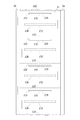
- the right-end elastic member 15 has a right-end elastic member 15 having a length equivalent to a plurality of pieces in the vertical direction of the mask main body 1, and is in a stretched state.
- the right end It is connected to the protruding portion of the outer surface side non-woven fabric 1a to be the folded portion 13.
- the left end elastic member 16 has a left end elastic member 16 having a length equivalent to a plurality of vertical lengths of the mask main body 1, and the mask main body 1 is manufactured in a stretched state.
- the non-woven fabric 1a is connected to the protruding portion.
- a specific connection method for example, a predetermined glue or a hot melt adhesive may be used for adhesion.
- the specific number and position of the connecting portions formed are not limited to those shown in FIG. 8, and can be changed as appropriate. As will be described later, since the pleats are formed at positions between the connecting portions in the vertical direction, the number and positions of pleats formed in the seventh step described later can be adjusted accordingly.
- both the right end elastic member 15 and the left end elastic member 16 are attached in a state of being extended from 150% to 250% of the original length.
- each sheet material is pulled in the feeding direction of the sheet material (longitudinal direction of the sheet material in FIG. 8) and tension is applied. Therefore, even if the right end elastic member 15 and the left end elastic member 16 are attached in a stretched state, the sheet material forming the mask main body 1 does not contract at this stage.
- the fourth step is a step of forming the right end folded portion 13 and the left end folded portion 14.
- the protruding portions of both ends of the outer surface side non-woven fabric 1a are folded back toward the wearer side non-woven fabric 1c so as to cover the ends of the filter 1b and the wearer side non-woven fabric 1c. Then, the right end folded portion 13 and the left end folded portion 14 are formed.
- the right first connecting portion 151, the right second connecting portion 152, the right third connecting portion 153, the right fourth connecting portion 154, and the right fifth connecting portion of the wearer-side nonwoven fabric 1c is also provided at the positions corresponding to the connection portion 155 and the left first connection portion 161, the left second connection portion 162, the left third connection portion 163, the left fourth connection portion 164, and the left fifth connection portion 165.
- a predetermined glue is also provided at the positions corresponding to the connection portion 155 and the left first connection portion 161, the left second connection portion 162, the left third connection portion 163, the left fourth connection portion 164, and the left fifth connection portion 165.
- a hot melt adhesive or the like so that the right end elastic member 15 and the left end elastic member 16 are also adhered to the non-woven fabric 1c on the wearer side at each connection portion. This strengthens the attachment of the right end elastic member 15 and the left end elastic member 16.
- this is not essential, and the right end elastic member 15 and the left end elastic member 16 may be adhered only
- the fifth step is a step of forming the right end joint portion 123 and the left end joint portion 124.
- the outer surface side nonwoven fabric 1a, the filter 1b, the wearer side is formed by joining the sheet materials that overlap the four layers of the non-woven fabric 1c and the outer surface side non-woven fabric 1a forming the right end folded portion 13 in a straight line parallel to the feeding direction of each sheet material. .. Further, in the vicinity of the right end portion (end portion from the center of the mask body 1) of the folded left end folded portion 14, the outer surface side nonwoven fabric 1a, the filter 1b, the wearer side nonwoven fabric 1c, and the outer surface forming the left end folded portion 14.
- the left end joining portion 124 is formed by joining the sheet materials that overlap the four layers of the side nonwoven fabric 1a in a straight line parallel to the feeding direction of each sheet material.
- a specific joining method of the sheet materials here, for example, heat and ultrasonic waves may be used for welding.
- the sixth step is a step of forming the ear hook.
- the right ear-hooking part 2 connects the continuous string-shaped member to the upper part of the right end folding part 13 and the lower part of the right end folding part 13 in each mask body part 1. It is formed by welding at a certain position by, for example, heat or ultrasonic waves.
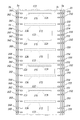
- FIG. 10 shows that by attaching continuous string-like members formed of a stretchable material such as polyurethane to both ends of each sheet material in a direction orthogonal to the feeding direction.
- the ear hook 2 and the left ear hook 3 are formed.
- the right ear-hooking part 2 connects the continuous string-shaped member to the upper part of the right end folding part 13 and the lower part of the right end folding part 13 in each mask body part 1. It is formed by welding at a certain position by, for example, heat or ultrasonic waves.
- the left ear-hooking portion 3 includes continuous string-shaped members at positions which are the upper portion of the left end folding portion 14 and the lower portion of the left end folding portion 14 in each mask body portion 1. It is formed by welding with, for example, heat or ultrasonic waves.
- the right ear hook 2 and the left ear hook 3 which are continuously formed will be separated together with the mask body 1 in the seventh step.
- the seventh step is a step of cutting the sheet material forming the mask main body 1. By this step, the mask main body 1 formed in succession is separated into one piece at a time.
- each of the mask main body portions 1 is separated by cutting the sheet material in a straight line perpendicular to the feeding direction of the sheet material.
- the right ear-hooking part 2 and the left ear-hooking part 3 which were formed by continuously attaching the string-like members in the sixth step, are also cut and separated for each mask main body part 1.
- the Rukoto is also cut and separated for each mask main body part 1.
- each sheet material is pulled in the feeding direction of each sheet material (longitudinal direction of the sheet material in FIGS. 6 to 10) and tension is applied, Even if the right end elastic member 15 and the left end elastic member 16 are attached in a stretched state, the sheet material forming the mask main body 1 does not contract.
- the seventh step if the sheet material is cut and the mask main body 1 is separated one by one, the above tension is not applied. Then, the right-end elastic member 15 and the left-end elastic member 16 attached in the stretched state in the third step contract, and the mask main body 1 is accompanied by the extension direction of each sheet material (use of the mask 100). Will contract in the vertical direction).
- the right end elastic member 15 includes the right first connecting portion 151, the right second connecting portion 152, the right third connecting portion 153, the right fourth connecting portion 154, and the right fifth connecting portion 155.
- the left end elastic member 16 is connected to the sheet material (right end folded-back portion 13 and wearer side non-woven fabric 1c) forming the mask main body 1 at five locations, and the left end elastic member 16 is connected to the left first connection portion 161 and the left second connection.
- Sheet material (left end folded-back portion 14 and wearer-side non-woven fabric 1c) forming the mask main body portion 1 at five locations of the portion 162, the left third connecting portion 163, the left fourth connecting portion 164, and the left fifth connecting portion 165. ), the right end elastic member 15 and the left end elastic member 16 pull these connecting portions and contract so as to reduce the distance between them.
- each sheet material forming the mask main body 1 is connected to each connecting portion. At a position between them, as shown in FIG. 3, it contracts so as to project to the front side (outer surface side nonwoven fabric 1a side).
- the first connection portion 151 passes between the first right connection portion 151 and the second right connection portion 152, and the first connection portion 161 on the left passes between the second connection portion 162 on the left.
- the pleat 111 is formed, and the second pleat 112 is formed so as to pass between the right second connecting portion 152 and the right third connecting portion 153 and between the left second connecting portion 162 and the left third connecting portion 163.
- the third pleat 113 is formed so as to pass between the right third connecting portion 153 and the right fourth connecting portion 154 and between the left third connecting portion 163 and the left fourth connecting portion 164.
- the fourth pleat 114 is formed so as to pass between the fourth connecting portion 154 and the right fifth connecting portion 155 and between the left fourth connecting portion 164 and the left fifth connecting portion 165.
- the right end elastic member 15 and the left end elastic member 16 are covered by the right end folded portion 13 or the left end folded portion 14, the right end elastic member Since the mask 15 and the left end elastic member 16 are provided, it is possible to prevent the appearance and wearing feeling of the mask from being impaired.
- the right end elastic member 15 and the left end elastic member 16 are provided at the left and right ends of the mask main body 1 so as to extend in the vertical direction, so that the mask main body when the mask 100 is worn.
- the airtightness on the left and right sides of part 1 can also be improved.
- the mask 100A according to the second embodiment does not form the right end folded portion 13 and the left end folded portion 14 with respect to the mask main body portion 1A, and instead, as shown in FIGS. 11 to 13, the outer surface side non-woven fabric 1a, It includes a right gather sheet 18 and a left gather sheet 19 formed of a sheet material separate from the filter 1b and the non-woven fabric 1c on the wearer side. Further, the right end elastic member 15 is provided on the right gather sheet 18, and the left end elastic member 16 is provided on the left gather sheet 19.
- the right gather sheet 18 and the left gather sheet 19 are sheet materials having the same length as the outer surface side non-woven fabric 1a, the filter 1b and the wearer side non-woven fabric 1c which form the mask body 1 in the vertical direction, as shown in FIG. It is formed by folding so as to have a Z-shaped cross section. As a result, as shown in FIG. 13, the right gather sheet 18 is formed with the first surface portion 181, the second surface portion 182 and the third surface portion 183, and the left gather sheet 19 is formed with the first surface portion 191 and the second surface portion. 192 and a third surface portion 193 are formed.
- the type of sheet material forming the right gather sheet 18 and the left gather sheet 19 is not particularly limited, but for example, the same sheet material as the wearer-side nonwoven fabric 1c may be used. Further, in the right gather sheet 18 and the left gather sheet 19, the widths of the first surface portion, the second surface portion and the third surface portion are substantially equal, and the widths of the first surface portion, the second surface portion and the third surface portion are 8 mm to 18 mm, respectively. Is preferably formed.
- the right gather sheet 18 is configured such that the end portion of the first surface portion 181 not connected to the second surface portion 182 is aligned with the right end portion of the mask main body portion 1 so that the wearer wears it. It is connected to the side nonwoven fabric 1c. Further, the left gather sheet 19 is connected to the non-woven fabric 1c on the wearer side so that the end portion of the first surface portion 191 on the side not connected to the second surface portion 192 coincides with the left end portion of the mask main body portion 1. Has been done.
- the right gather sheet 18 and the left gather sheet 19 are formed by, for example, attaching the entire surface of the first surface portion 181 or the first surface portion 191 to the non-woven fabric 1c on the wearer side using a predetermined glue, hot melt adhesive, or the like. It is connected to the side non-woven fabric 1c.
- the right end elastic member 15 is provided on the right gather sheet 18 so as to be sandwiched between the second surface portion 182 and the third surface portion 183, and the left end elastic member 16 is provided in FIG. 123.
- the left gather sheet 19 is provided so as to be sandwiched between the second surface portion 192 and the third surface portion 193.
- the right end elastic member 15 is sandwiched between the second surface portion 182 and the third surface portion 183 of the right gather sheet 18 as shown in FIG. 13, and as shown in FIG. From the right first connecting portion 151A, the right second connecting portion 152A, the right third connecting portion 153A, the right fourth connecting portion 154A and the right fifth connecting portion 155A), as shown in FIG. It is connected to both sides of the three-sided portion 183.
- the left end elastic member 16 is sandwiched between the second surface portion 192 and the third surface portion 193 of the left gather sheet 19 as shown in FIG. 13, and as shown in FIG. (From the top, the left first connecting portion 161A, the left second connecting portion 162A, the left third connecting portion 163A, the left fourth connecting portion 164A, and the left fifth connecting portion 165A), as shown in FIG. And the third surface portion 193.
- the connecting portions are vertically spaced so as to avoid pleats and are located between them in the vertical direction (right first connecting portion 151A and left first connecting portion 161A).
- the third connecting portion 153A and the left third connecting portion 163A are located between the second pleat 112 and the third pleat 113
- the right fourth connecting portion 154A and the left fourth connecting portion 164A are located between the third pleat 113 and the fourth pleat 113.
- the right fifth connecting portion 155A and the left fifth connecting portion 165A are formed between the fourth pleat 114 and the lower end portion of the mask body 1A).
- the right ear hook 2 and the left ear hook 3 are both formed by attaching a string-like member made of a stretchable material such as polyurethane to the mask body 1. ing.
- the right ear hook 2 is on the right side of the mask body 1A, and one end of the string-shaped member is near the upper right end of the wearer-side nonwoven fabric 1c of the mask body 1A. It is welded by heat, ultrasonic waves, or the like, and the other end is welded to the vicinity of the lower right end of the non-woven fabric 1c on the wearer side by heat, ultrasonic waves, or the like, and is fixed to the mask body 1A.
- the left ear hook 3 On the left side of the mask body 1A, the left ear hook 3 has one end of a string-shaped member welded to the vicinity of the upper left end of the wearer-side nonwoven fabric 1c of the mask body 1A by heat, ultrasonic waves, or the like. The other end is fixed to the mask body 1A such that it is welded to the vicinity of the lower left end of the wearer-side nonwoven fabric 1c of the mask body 1A by heat, ultrasonic waves, or the like.
- the right gather sheet 18 is attached from above the connection portion of the right ear hook 2 to the wearer-side nonwoven fabric 1c, and the left gather sheet 19 from the connection portion of the left ear hook 3 to the wearer-side nonwoven fabric 1c.
- the attachment portion of the right ear hook 2 to the mask body 1A is sandwiched between the wearer-side nonwoven fabric 1c and the right gather sheet 18, and the left ear hook 3 is attached to the mask body 1A.
- the attachment portion is sandwiched between the wearer-side nonwoven fabric 1c and the left gather sheet 19.
- the method of fixing the right ear hooking portion 2 and the left ear hooking portion 3 to the mask body portion 1A is not limited to the above, and for example, both ends thereof may be between the outer surface side nonwoven fabric 1a and the filter 1b or the filter 1b.
- each sheet material is formed by the right end joint portion 123A and the left end joint portion 124A.
- the right ear hook 2 and the left ear hook 3 may be fixed to the mask main body 1.
- the mask body portion 1A does not include the right end folded portion 13 and the left end folded portion 14, and the right end joint portion 123A and the left end joint portion 124A have the outer surface as shown in FIGS. 11 and 13.
- the three layers of the side non-woven fabric 1a, the filter 1b, and the wearer side non-woven fabric 1c are joined in the front-rear direction by, for example, heat or ultrasonic waves, and extend vertically along the right end portion or the left end portion of the mask body 1A. It is formed in a straight line.
- the method for manufacturing the mask 100A comprises six steps from the first step to the sixth step. The description of the same parts as those in the method of manufacturing the mask 100 according to the first embodiment will be omitted.
- the first step is a step of laminating the sheet material constituting the mask main body 1.
- a sheet roll in which a long sheet material is wound in a roll shape is used for the sheet material forming each of the outer surface side nonwoven fabric 1a, the filter 1b, and the wearer side nonwoven fabric 1c.
- the nonwoven fabric 1c is laminated in this order.
- the right end folded-back portion 13 and the left end folded-back portion 14 are not necessary, and thus the rolled outer surface side nonwoven fabrics of the roll sheets R1, R2, and R3.
- 1a, the filter 1b and the wearer-side non-woven fabric 1c are formed so that the width of the mask body 1 to be manufactured matches the width of the mask body 1 in the left-right direction, and as shown in FIG.
- the side non-woven fabric 1a, the filter 1b, and the wearer side non-woven fabric 1c may be laminated so that they substantially overlap each other.
- each sheet material is not limited to the above, and for example, it is possible to form the right end folded portion 13 and the left end folded portion 14 in the same manner as in the first embodiment. Further, similarly to the first embodiment, the width of the outer surface side nonwoven fabric 1a is formed to be wider than that of the filter 1b and the wearer side nonwoven fabric 1c, and the right end folded portion 13 and the left end folded portion 14 are not formed.
- the protruding portion may be used as it is, for example, as a fixed portion of the ear hooking portion.
- the nose portion reinforcing member 171 and the mouth portion reinforcing member 172 are provided at predetermined positions between the wearer-side nonwoven fabric 1c and the filter 1b.
- the longitudinal direction thereof is arranged so as to coincide with the feeding direction of each sheet material and the direction orthogonal to the feeding direction (the lateral direction of the sheet material in FIG. 14).
- the second step is a step of forming the upper end joint portion 121, the lower end joint portion 122, the right end joint portion 123A, the left end joint portion 124A, the nose portion reinforcing member peripheral joint portion 125, and the mouth portion reinforcing member peripheral joint portion 126. is there.
- the outer surface side non-woven fabric 1a, the filter 1b and the wearer side non-woven fabric 1c which are laminated as described above, after cutting in the subsequent sixth step
- the upper end joining portion 121 is formed by joining the sheet materials along the upper end portion of the mask main body portion 1A in a straight line orthogonal to the feeding direction of the sheet material, and the mask main body portion 1 after cutting in the subsequent sixth step.
- the lower end joint portion 122 is formed by linearly joining the sheet materials along the lower end portion thereof in a direction orthogonal to the feeding direction.
- the outer surface side non-woven fabric 1a, the filter 1b, and the wearer side non-woven fabric 1c are joined in a straight line parallel to the feeding direction of each sheet material along the right end portion of the mask main body portion 1A after cutting in the sixth step.
- the right end joint 123A is formed, and along the left end of the mask main body 1A after cutting in the subsequent sixth step, the outer surface side nonwoven fabric 1a and the filter are formed in a straight line parallel to the feeding direction of each sheet material.
- the left end joining portion 124A is formed. Further, as shown in FIG.
- the outer surface side non-woven fabric 1a, the filter 1b, and the wearer side non-woven fabric 1c are joined so as to surround the nose reinforcing member 171 and the mouth reinforcing member 172 to join the periphery of the nose reinforcing member.
- the portion 125 and the mouth reinforcing member peripheral joint portion 126 are formed.
- the third step is a step of forming the ear hook.
- continuous string-shaped members formed of a stretchable material such as polyurethane are attached to both ends in a direction orthogonal to the feeding direction of each sheet material.
- the right ear hook 2 and the left ear hook 3 are formed.
- the right ear hook portion 2 has a continuous string-shaped member, in each mask main body portion 1, on the rear surface side of the mask main body portion 1 (wearer side non-woven fabric 1c side). It is formed by welding by, for example, heat or ultrasonic waves at a position near the right upper end portion and near the right lower end portion on the rear surface side (wearer side non-woven fabric 1c side) of the mask body 1. Further, as shown in FIG.
- the left ear hook portion 3 has a continuous string-shaped member, in each mask main body portion 1, the upper left end portion of the mask main body 1 rear surface side (wearer side non-woven fabric 1c side). It is formed by welding by, for example, heat or ultrasonic waves at a position near the left lower end portion on the rear surface side (wearer side non-woven fabric 1c side) of the mask main body portion 1.
- the right ear hook 2 and the left ear hook 3 which are continuously formed are separated together with the mask body 1A in the sixth step.
- the method of attaching the right ear hook 2 and the left ear hook 3 is not limited to this.
- the first step between the outer surface side nonwoven fabric 1a and the filter 1b or between the filter 1b and the wearer side nonwoven fabric 1c.
- a string-shaped member made of a stretchable material such as polyurethane is arranged so that both ends are sandwiched between them, and the members including the string-shaped member are joined together.
- the right end joint 123A Also, it may be joined to the mask body 1A by forming the left end joining portion 124A.
- the fourth step is a step of forming the right gather sheet 18 and the left gather sheet 19.
- a long sheet material having a width that is the sum of the widths of the first surface portion 181 and the second surface portion 182 and the third surface portion 183 of the right gather sheet 18 in the lateral direction, and the left in the lateral direction A long sheet material having a width obtained by combining the widths of the first surface portion 191, the second surface portion 192, and the third surface portion 193 of the gather sheet 19 is folded into three equal parts in the lateral direction.
- a right gather sheet 18 having a surface portion 181 and a second surface portion 182 and a third surface portion 183 and a left gather sheet 19 having a first surface portion 191 and a second surface portion 192 and a third surface portion 193 are formed.
- the right gather sheet 18 has an end portion of the first surface portion 181 that is not connected to the second surface portion 182 so as to coincide with the right end portion of the mask main body portion 1.
- the wearer-side nonwoven fabric 1c is connected as shown in FIG.
- the left gather sheet 19 is configured such that an end portion of the first surface portion 191 that is not connected to the second surface portion 192 coincides with a left end portion of the mask main body portion 1, As shown in FIG. 17, it is connected to the wearer-side nonwoven fabric 1c.
- the right gather sheet 18 sandwiches the connecting portions at both ends of the right ear hook 2 between the wearer-side nonwoven fabric 1c, and the left gather sheet 19 holds both end portions of the left ear hook 3.
- the connecting portion of the above is attached so as to be sandwiched between the non-woven fabric 1c on the wearer side.
- the right ear hook 2 and the left ear hook 3 are firmly fixed to the mask body 1, and the connection portions of the right ear hook 2 and the left ear hook 3 to the mask body 1 are formed. Since it is covered with the right gather sheet 18 or the left gather sheet 19, the wearing feeling of the mask can be improved.
- the right gather sheet 18 and the left gather sheet 19 are attached to the non-woven fabric 1c on the wearer side by, for example, attaching the entire surface of the first surface portion 181 or the first surface portion 191 using a predetermined glue, hot melt adhesive, or the like. ..
- the fifth step is a step of attaching the right end elastic member 15 and the left end elastic member 16.
- the right end elastic member 15 is sandwiched between the second surface portion 182 and the third surface portion 183 of the right gather sheet 18 in a stretched state as shown in FIG.
- the left end elastic member 16 is attached to both the surface portion 182 and the third surface portion 183, and the left end elastic member 16 is extended between the second surface portion 192 and the third surface portion 193 of the left gather sheet 19 as shown in FIG. It is attached to both the second surface portion 192 and the third surface portion 193 so as to be sandwiched.
- the right end elastic member 15 is provided with the right end elastic member 15 having a length corresponding to a plurality of vertical lengths of the mask body 1A.
- the left end elastic member 16 is provided with the left end elastic member 16 having a length corresponding to a plurality of vertical lengths of the mask main body 1A.
- the left first connecting portion 161A, the left second connecting portion 162A, the left third connecting portion 163A, the left fourth connecting portion 164A, and the left fifth connecting portion 165A are connected to the second surface portion 192 and the third surface portion 193.
- a connection method for example, a predetermined glue, a hot melt adhesive, or the like may be used for adhesion.
- the specific number and position of the connecting portions formed are not limited to those shown in FIG. 18, and can be changed as appropriate.
- the pleats are formed at positions between the connecting portions in the vertical direction, so that the number and position of pleats formed in the sixth step described later can be adjusted.
- the fourth step and the fifth step are not limited to the above order, and after attaching the right end elastic member 15 to the right gather sheet 18, the right gather sheet 18 is attached to the wearer side non-woven fabric 1c, and the left end portion. After attaching the elastic member 16 to the left gather sheet 19, the left gather sheet 19 may be attached to the non-woven fabric 1c on the wearer side.
- each sheet material is pulled in the feeding direction of the sheet material (longitudinal direction of the sheet material in FIG. 18) and tension is applied. Therefore, even if the right end elastic member 15 and the left end elastic member 16 are attached in a stretched state, the sheet material forming the mask main body 1 does not contract at this stage.
- the sixth step is a step of cutting the sheet material forming the mask main body 1A. By this step, the mask main body portions 1A which are continuously formed are separated one by one.
- each of the mask main body 1A is separated by cutting in a straight line perpendicular to the feeding direction of the sheet material.
- the right ear-hooking part 2 and the left ear-hooking part 3 which were formed by continuously attaching the string-shaped members in the third step, are also cut and separated for each mask main body part 1A.
- the Rukoto is also cut and separated for each mask main body part 1A.
- each sheet material is pulled in the feeding direction of each sheet material (longitudinal direction of the sheet material in FIGS. 14 to 18) and tension is applied, Even if the right end elastic member 15 and the left end elastic member 16 are attached in a stretched state, the sheet material forming the mask body 1A does not contract.
- the tension is not applied, and the state in which the sheet is stretched in the fifth step is eliminated.
- the mask main body 1A contracts in the feeding direction (vertical direction when the mask 100A is used) of each sheet material. Become.
- the right end elastic member 15 includes the right first connection portion 151A, the right second connection portion 152A, the right third connection portion 153A, the right fourth connection portion 154A, and the right fifth connection portion 155A.
- the left end elastic member 16 is connected to the sheet material (right gather sheet 18) forming the mask main body 1A at five locations, the left first connection portion 161A, the left second connection portion 162A, and the left third connection.
- the right end elastic member 15 is connected to the sheet material (the left gather sheet 19) forming the mask main body 1A at five portions of the portion 163A, the left fourth connecting portion 164A, and the left fifth connecting portion 165A.
- the left end elastic member 16 pulls these connecting portions and contracts so as to reduce the distance between them.
- each sheet material forming the mask main body 1 is connected to each connecting portion.
- the contraction is performed so as to project to the front side (outer surface side nonwoven fabric 1a side).
- the first first connecting portion 151A and the second right connecting portion 152A and the left first connecting portion 161A and the left second connecting portion 162A are passed through the first first connecting portion 151A and the right second connecting portion 152A.
- the pleats 111 are formed, and the second pleats 112 are formed so as to pass between the right second connection portion 152A and the right third connection portion 153A and between the left second connection portion 162A and the left third connection portion 163A.
- the third pleat 113 is formed so as to pass between the right third connecting portion 153A and the right fourth connecting portion 154A and between the left third connecting portion 163A and the left fourth connecting portion 164A.
- the fourth pleat 114 is formed so as to pass between the fourth connecting portion 154A and the right fifth connecting portion 155A and between the left fourth connecting portion 164A and the left fifth connecting portion 165A.
- the right end elastic member 15 is provided on the right gather sheet 18 so as to be sandwiched between the second surface portion 182 and the third surface portion 183 and covered. Since the left end elastic member 16 is provided on the left gather sheet 19 so as to be sandwiched and covered between the second surface portion 192 and the third surface portion 193, the right end elastic member 15 and the left end portion 16 are provided. By providing the elastic member 16, it is possible to prevent the appearance and wearing feeling of the mask from being impaired.
- the right end elastic member 15 and the left end elastic member 16 are provided at the left and right ends of the mask main body 1A so as to extend in the vertical direction, the mask main body when the mask 100A is worn. It is also possible to improve the hermeticity of the left and right parts 1A. Further, since the right gather sheet 18 and the left gather sheet 19 fill the gap, the left and right hermeticity of the mask main body 1A can be further improved as compared with the first embodiment which does not include this.
- the present invention can be suitably used in the field of mask manufacturing.
Landscapes
- Health & Medical Sciences (AREA)
- General Health & Medical Sciences (AREA)
- Life Sciences & Earth Sciences (AREA)
- Zoology (AREA)
- Pulmonology (AREA)
- Business, Economics & Management (AREA)
- Emergency Management (AREA)
- Physical Education & Sports Medicine (AREA)
- Engineering & Computer Science (AREA)
- Textile Engineering (AREA)
- Respiratory Apparatuses And Protective Means (AREA)
Abstract
シート材で形成され、着用者の顔面の対象部位を覆うマスク本体部1と、マスク本体部1を着用者の耳に係止するための右耳掛け部2及び左耳掛け部3と、を備えるマスク100であって、マスク本体部1は、上下方向に広げることができる複数のプリーツと、弾性を有する材料によって形成され、マスク本体部1の左右それぞれの端部近傍に上下方向に延在するように備えられた右端部弾性部材15及び左端部弾性部材16と、を備え、右端部弾性部材15及び左端部弾性部材16は、上下方向に所定の間隔を空けて形成された複数の接続部においてマスク本体部1を形成するシート材に接続され、複数のプリーツは、上下方向に前記接続部の間となる位置に形成されている。これによって、製造効率を向上させることができるマスク及びマスクの製造方法を提供することができる。
Description
本発明は、マスク及びマスクの製造方法に関する。
疾病時、花粉又は黄砂等の粉塵飛来時、その他の日常生活において使用されるマスクとして、マスク本体部にプリーツが形成され、着用時には上下方向に展開させることを可能としたものが存在している(例えば、特許文献1参照)。
このようなマスクは、プリーツを上下方向に広げて着用することにより、マスク本体部が山型の立体的形状となり、着用者の鼻や口の周辺に空間が形成され、着用者が呼吸し易くなる点等に利点がある。
このようなマスクは、プリーツを上下方向に広げて着用することにより、マスク本体部が山型の立体的形状となり、着用者の鼻や口の周辺に空間が形成され、着用者が呼吸し易くなる点等に利点がある。
このようなプリーツタイプのマスクの製造方法としては、マスク本体部の左右方向の長さ複数枚分の長さを有するシート材をその長手方向へと流しつつ、その長手方向と平行にプリーツを形成した後に、当該シート材を、形成されたプリーツと直行する切り目において所定の長さにカットすることによってマスク本体部を形成し、さらに、形成されたマスク本体部を90°回転させた上で、マスク本体部の左右両端部付近に耳掛け部を形成するゴム紐を取り付けるという過程を経る製造方法が知られている(例えば、特許文献2参照)。
特許文献2に記載の発明のような従来の製造方法においては、製造工程において、プリーツが形成されたシート材をカットしてマスク本体部を形成した状態のままでは、形成されたマスク本体部が、その左右の端部同士が接するようにして配置されていることから、このままではマスク本体部の左右両端部付近にゴム紐を取り付けて耳掛け部を形成することは困難であった。
そこで、形成されたマスク本体部を90°回転させる工程が必須となることから、マスク本体部を形成するシート材を一定の方向に流しつつ、一連の工程でマスクを製造することができず、製造効率の向上が困難であった。
そこで、形成されたマスク本体部を90°回転させる工程が必須となることから、マスク本体部を形成するシート材を一定の方向に流しつつ、一連の工程でマスクを製造することができず、製造効率の向上が困難であった。
本発明は、製造効率を向上させることができるマスク及びマスクの製造方法を提供することを目的とする。
上記課題を解決するために、請求項1に記載の発明は、
シート材で形成され、着用者の顔面の対象部位を覆うマスク本体部と、当該マスク本体部を前記着用者の耳に係止するための左右一対の耳掛け部と、を備えるマスクであって、
前記マスク本体部は、
上下方向に広げることができる複数のプリーツと、
弾性を有する材料によって形成され、当該マスク本体部の左右それぞれの端部近傍に上下方向に延在するように備えられた弾性部材と、
を備え、
前記弾性部材は、上下方向に所定の間隔を空けて形成された複数の接続部においてマスク本体部を形成するシート材に接続され、前記プリーツは、上下方向に前記接続部の間となる位置に形成されていることを特徴とする。
本発明によれば、製造効率を向上することができるマスクを提供することができる。
シート材で形成され、着用者の顔面の対象部位を覆うマスク本体部と、当該マスク本体部を前記着用者の耳に係止するための左右一対の耳掛け部と、を備えるマスクであって、
前記マスク本体部は、
上下方向に広げることができる複数のプリーツと、
弾性を有する材料によって形成され、当該マスク本体部の左右それぞれの端部近傍に上下方向に延在するように備えられた弾性部材と、
を備え、
前記弾性部材は、上下方向に所定の間隔を空けて形成された複数の接続部においてマスク本体部を形成するシート材に接続され、前記プリーツは、上下方向に前記接続部の間となる位置に形成されていることを特徴とする。
本発明によれば、製造効率を向上することができるマスクを提供することができる。
請求項2に記載の発明は、請求項1に記載のマスクにおいて、
前記マスク本体部は、
最前面に配置された外面側シート材を、右端部を回り込むようにして後面側へと折り返した右端部折り返し部と、
前記外面側シート材を、左端部を回り込むようにして後面側へと折り返した左端部折り返し部と、
を備え、
前記弾性部材は、
最後面に配置された着用者側シート材と前記右端部折り返し部との間と、
前記着用者側シート材と前記左端部折り返し部との間と、
に備えられていることを特徴とする。
本発明によれば、装着感の悪化を抑制しつつ、製造効率を向上することができるマスクを提供することができる。
前記マスク本体部は、
最前面に配置された外面側シート材を、右端部を回り込むようにして後面側へと折り返した右端部折り返し部と、
前記外面側シート材を、左端部を回り込むようにして後面側へと折り返した左端部折り返し部と、
を備え、
前記弾性部材は、
最後面に配置された着用者側シート材と前記右端部折り返し部との間と、
前記着用者側シート材と前記左端部折り返し部との間と、
に備えられていることを特徴とする。
本発明によれば、装着感の悪化を抑制しつつ、製造効率を向上することができるマスクを提供することができる。
請求項3に記載の発明は、請求項1に記載のマスクにおいて、
着用者側の面の左右端部近傍に、当該面から起立するように形成されたギャザーシートを備え、
前記弾性部材は、前記ギャザーシートに備えられていることを特徴とする。
本発明によれば、マスク左右の密閉性を向上しつつ、製造効率を向上することができるマスクを提供することができる。
着用者側の面の左右端部近傍に、当該面から起立するように形成されたギャザーシートを備え、
前記弾性部材は、前記ギャザーシートに備えられていることを特徴とする。
本発明によれば、マスク左右の密閉性を向上しつつ、製造効率を向上することができるマスクを提供することができる。
請求項4に記載の発明は、請求項3に記載のマスクにおいて、
前記ギャザーシートは、前記マスク本体部の最後面に配置された着用者側シート材と接続された第1面部と、前記第1面部の端部に接続された第2面部と、前記第2面部の前記第1面部と接続されているのと反対側の端部に接続された第3面部と、を備え、
前記弾性部材は、前記第2面部と前記第3面部との間に備えられていることを特徴とする。
本発明によれば、装着感の悪化を抑制しつつ、製造効率を向上することができるマスクを提供することができる。
前記ギャザーシートは、前記マスク本体部の最後面に配置された着用者側シート材と接続された第1面部と、前記第1面部の端部に接続された第2面部と、前記第2面部の前記第1面部と接続されているのと反対側の端部に接続された第3面部と、を備え、
前記弾性部材は、前記第2面部と前記第3面部との間に備えられていることを特徴とする。
本発明によれば、装着感の悪化を抑制しつつ、製造効率を向上することができるマスクを提供することができる。
請求項5に記載の発明は、マスクの製造方法において、
長手方向にマスク本体部の上下方向の長さ複数枚分の長さを有するシート材の短手方向の両端部近傍に、弾性を有する材料によって形成された弾性部材を、当該端部に沿う方向に引き伸ばされた状態で、所定の間隔を空けて形成された接続部において接続する弾性部材取付工程と、
前記シート材に、耳掛け部を形成する耳掛け部形成工程と、
前記シート材を、マスク本体部の上下方向の幅に切断する切断工程と、
を含むことを特徴とする。
本発明によれば、製造効率を向上することができるマスクの製造方法を提供することができる。
長手方向にマスク本体部の上下方向の長さ複数枚分の長さを有するシート材の短手方向の両端部近傍に、弾性を有する材料によって形成された弾性部材を、当該端部に沿う方向に引き伸ばされた状態で、所定の間隔を空けて形成された接続部において接続する弾性部材取付工程と、
前記シート材に、耳掛け部を形成する耳掛け部形成工程と、
前記シート材を、マスク本体部の上下方向の幅に切断する切断工程と、
を含むことを特徴とする。
本発明によれば、製造効率を向上することができるマスクの製造方法を提供することができる。
請求項6に記載の発明は、請求項5に記載のマスクの製造方法において、
複数枚の前記シート材を積層する積層工程を含むことを特徴とする。
本発明によれば、製造効率を向上することができるマスクの製造方法を提供することができる。
複数枚の前記シート材を積層する積層工程を含むことを特徴とする。
本発明によれば、製造効率を向上することができるマスクの製造方法を提供することができる。
請求項7に記載の発明は、請求項6に記載のマスクの製造方法において、
前記積層工程においては、マスク本体部最前面に位置する外面側シート材として、短手方向に他のシート材よりも長いシート材を用い、当該外面側シート材の短手方向両端部が露出するようにして前記シート材を積層し、
当該露出部分をマスク本体部後面側へと折り返し、右端部折り返し部及び左端部折り返し部を形成する折り返し部形成工程をさらに含み、
前記弾性部材取付工程においては、
前記右端部折り返し部と最後面に配置された着用者側シート材との間と、
前記左端部折り返し部と前記着用者側シート材との間と、
に配置されるようにして、前記弾性部材を取り付けることを特徴とする。
本発明によれば、製造されたマスクの装着感の悪化を抑制しつつ、製造効率を向上することができるマスクの製造方法を提供することができる。
前記積層工程においては、マスク本体部最前面に位置する外面側シート材として、短手方向に他のシート材よりも長いシート材を用い、当該外面側シート材の短手方向両端部が露出するようにして前記シート材を積層し、
当該露出部分をマスク本体部後面側へと折り返し、右端部折り返し部及び左端部折り返し部を形成する折り返し部形成工程をさらに含み、
前記弾性部材取付工程においては、
前記右端部折り返し部と最後面に配置された着用者側シート材との間と、
前記左端部折り返し部と前記着用者側シート材との間と、
に配置されるようにして、前記弾性部材を取り付けることを特徴とする。
本発明によれば、製造されたマスクの装着感の悪化を抑制しつつ、製造効率を向上することができるマスクの製造方法を提供することができる。
請求項8に記載の発明は、請求項5又は6に記載のマスクの製造方法において、
前記シート材のマスク本体部において着用者に向く面の短手方向両端部近傍に、当該シート材から起立するようにしてギャザーシートを取り付けるギャザーシート取付工程を含み、
前記弾性部材取付工程においては、
前記シート材に取り付けられた状態又は取り付けられる前の状態の前記ギャザーシートに、前記弾性部材を所定の間隔を空けて形成された接続部において接続することで、前記ギャザーシートを介して、前記シート材に前記弾性部材を取り付けることを特徴とする。
本発明によれば、マスク左右の密閉性を向上しつつ、製造効率を向上することができるマスクの製造方法を提供することができる。
前記シート材のマスク本体部において着用者に向く面の短手方向両端部近傍に、当該シート材から起立するようにしてギャザーシートを取り付けるギャザーシート取付工程を含み、
前記弾性部材取付工程においては、
前記シート材に取り付けられた状態又は取り付けられる前の状態の前記ギャザーシートに、前記弾性部材を所定の間隔を空けて形成された接続部において接続することで、前記ギャザーシートを介して、前記シート材に前記弾性部材を取り付けることを特徴とする。
本発明によれば、マスク左右の密閉性を向上しつつ、製造効率を向上することができるマスクの製造方法を提供することができる。
請求項9に記載の発明は、請求項8に記載のマスクの製造方法において、
前記弾性部材取付工程においては、前記ギャザーシートの間に挟まれるようにして前記弾性部材を取り付けることを特徴とする。
本発明によれば、製造されたマスクの装着感の悪化を抑制しつつ、製造効率を向上することができるマスクの製造方法を提供することができる。
前記弾性部材取付工程においては、前記ギャザーシートの間に挟まれるようにして前記弾性部材を取り付けることを特徴とする。
本発明によれば、製造されたマスクの装着感の悪化を抑制しつつ、製造効率を向上することができるマスクの製造方法を提供することができる。
本発明によれば、製造効率を向上させることができるマスク及びマスクの製造方法を提供することができる。
以下、本発明の実施形態であるマスク及びマスクの製造方法について、図1から図18に基づいて説明する。ただし、本発明の技術的範囲は図示例に限定されるものではない。
[第1実施形態]
第1実施形態に係るマスク100の構成及び製造方法につき、以下説明する。
第1実施形態に係るマスク100の構成及び製造方法につき、以下説明する。
{マスクの構成}
まず、第1実施形態に係るマスク100の構成について、図1から図4に基づいて説明する。
なお、以下においては、図1に示すように、マスクを着用者が着用した状態において、当該着用者から見た方向を基準として、前後、左右及び上下を定めて説明する。
まず、第1実施形態に係るマスク100の構成について、図1から図4に基づいて説明する。
なお、以下においては、図1に示すように、マスクを着用者が着用した状態において、当該着用者から見た方向を基準として、前後、左右及び上下を定めて説明する。
(全体構成)
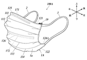
マスク100は、図1及び図2に示すように、着用者の顔面の鼻、口、顎等を覆うマスク本体部1と、マスク本体部1を着用者の右耳に掛止するための右耳掛け部2と、マスク本体部1を着用者の左耳に掛止するための左耳掛け部3と、を備えている。なお、マスク100は、マスク本体部1の後面側を着用者の顔面に向けて着用される。
マスク100は、図1及び図2に示すように、着用者の顔面の鼻、口、顎等を覆うマスク本体部1と、マスク本体部1を着用者の右耳に掛止するための右耳掛け部2と、マスク本体部1を着用者の左耳に掛止するための左耳掛け部3と、を備えている。なお、マスク100は、マスク本体部1の後面側を着用者の顔面に向けて着用される。
{マスク本体部}
マスク本体部1は、図1及び図2に示すように、複数のシート材によって正面視略矩形状に形成されている。
マスク本体部1は、左右方向に好ましくは120mmから210mm、さらに好ましくは145mmから175mm、上下方向に好ましくは70mmから100mm、さらに好ましくは80mmから90mmに形成される。
マスク本体部1は、図1及び図2に示すように、複数のシート材によって正面視略矩形状に形成されている。
マスク本体部1は、左右方向に好ましくは120mmから210mm、さらに好ましくは145mmから175mm、上下方向に好ましくは70mmから100mm、さらに好ましくは80mmから90mmに形成される。
マスク本体部1は、図3及び図4に示すように、着用者の肌から遠い面から順に、マスク本体部1の最前面(着用者の肌から最も遠い面)に位置する外面側不織布1a、フィルター1b、マスク本体部1の最後面(着用者の肌から最も近い面)に位置する着用者側不織布1cの順にシート材を積層して形成されている。
また、図2及び図4に示すように、マスク本体部1の左右両端部は、外面側不織布1aがマスクの左右を回り込むようにして後面側へと折り返され、右端部折り返し部13及び左端部折り返し部14が形成されている。
右端部折り返し部13及び左端部折り返し部14は、左右方向に5mmから20mmの幅を有することが好ましい。
また、図2及び図4に示すように、マスク本体部1の左右両端部は、外面側不織布1aがマスクの左右を回り込むようにして後面側へと折り返され、右端部折り返し部13及び左端部折り返し部14が形成されている。
右端部折り返し部13及び左端部折り返し部14は、左右方向に5mmから20mmの幅を有することが好ましい。
具体的なシート材としては、例えば外面側不織布1a及び着用者側不織布1cとして、ポリプロピレンスパンボンド、ポリエチレンスパンボンド、ナイロンスパンボンド等が用いられ、フィルター1bとして、ポリプロピレンメルトブロー、レーヨンスパンボンド等が用いられる。また、着用者側不織布1cには、保湿剤、柔軟剤、抗菌剤等を塗布することも可能である。
最も好適には、外面側不織布1aとしてポリプロピレンスパンボンドが用いられ、着用者側不織布1cとして保湿剤を塗布したナイロンスパンボンドが用いられ、これらの間に挟み込まれるフィルター1bとしてポリプロピレンメルトブローが用いられる。
最も好適には、外面側不織布1aとしてポリプロピレンスパンボンドが用いられ、着用者側不織布1cとして保湿剤を塗布したナイロンスパンボンドが用いられ、これらの間に挟み込まれるフィルター1bとしてポリプロピレンメルトブローが用いられる。
なお、マスク本体部1の構成は上記のものに限られず、さらに多数のシート材を積層してもよいし、3枚よりも少数のシート材から形成してもよい。
(プリーツ)
外面側不織布1a、フィルター1b及び着用者側不織布1cは、重ねられた上で、図3に示すように折れており、これによって、前面側に、図1から図3に示すように、左右方向に沿って延在し、前方に凸となる4か所のプリーツ(上から第1プリーツ111、第2プリーツ112、第3プリーツ113及び第4プリーツ114とする。)が形成されている。マスク100の着用時には、これらプリーツを上下方向に広げることによって、マスク本体部1を上下方向に展開させることができる
なお、プリーツの具体的な形成数及び配置はこれに限られず、これより多数又は少数のプリーツを形成してもよい。また、配置間隔も適宜変更可能である。
外面側不織布1a、フィルター1b及び着用者側不織布1cは、重ねられた上で、図3に示すように折れており、これによって、前面側に、図1から図3に示すように、左右方向に沿って延在し、前方に凸となる4か所のプリーツ(上から第1プリーツ111、第2プリーツ112、第3プリーツ113及び第4プリーツ114とする。)が形成されている。マスク100の着用時には、これらプリーツを上下方向に広げることによって、マスク本体部1を上下方向に展開させることができる
なお、プリーツの具体的な形成数及び配置はこれに限られず、これより多数又は少数のプリーツを形成してもよい。また、配置間隔も適宜変更可能である。
(接合部)
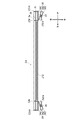
マスク本体部1を形成する外面側不織布1a、フィルター1b及び着用者側不織布1cは、上下及び左右の端部付近において、例えば熱・超音波等によって前後に溶着されており、図1から図3に示すように、上端部付近に上端部接合部121、下端部付近に下端部接合部122が形成され、図1、図2及び図4に示すように、右端部付近に右端部接合部123、左端部付近に左端部接合部124が形成されている。
マスク本体部1を形成する外面側不織布1a、フィルター1b及び着用者側不織布1cは、上下及び左右の端部付近において、例えば熱・超音波等によって前後に溶着されており、図1から図3に示すように、上端部付近に上端部接合部121、下端部付近に下端部接合部122が形成され、図1、図2及び図4に示すように、右端部付近に右端部接合部123、左端部付近に左端部接合部124が形成されている。
図1及び図2に示すように、上端部接合部121はマスク本体部1の上端部に沿って左右方向に延在する直線状に形成され、下端部接合部122はマスク本体部1の下端部に沿って右左方向に延在する直線状に形成されている。
また、図2に示すように、右端部接合部123は右端部折り返し部13のマスク本体部1中央よりの端部に沿って上下方向に延在する直線状に形成され、左端部接合部124は左端部折り返し部14のマスク本体部1中央寄りの端部に沿って上下方向に延在する直線状に形成されている。
また、図2に示すように、右端部接合部123は右端部折り返し部13のマスク本体部1中央よりの端部に沿って上下方向に延在する直線状に形成され、左端部接合部124は左端部折り返し部14のマスク本体部1中央寄りの端部に沿って上下方向に延在する直線状に形成されている。
また、図1から図3に示すように、後述の鼻部補強部材171を囲むようにして、外面側不織布1a、フィルター1b及び着用者側不織布1cを熱・超音波等によって前後に溶着させることで、鼻部補強部材周辺接合部125が形成され、図1から図4に示すように、後述の口部補強部材172を囲むようにして、外面側不織布1a、フィルター1b及び着用者側不織布1cを熱・超音波等によって前後に溶着させることで、口部補強部材周辺接合部126が形成されている。
なお、いずれの接合部についても、具体的な接合方法は特に限定されず、例えば、実線状に当該接合部の全体においてシート材同士を接合してもよいし、破線上に断続的にシート材同士を接合してもよい。
(弾性部材)
マスク本体部1は、右端部近傍に、弾性を有する材料によって、マスク本体部1の右端部に沿って上下方向に延在するようにして右端部弾性部材15を備え、左端部近傍に、弾性を有する材料によって、マスク本体部1の左端部に沿って上下方向に延在するようにして左端部弾性部材16を備える。
マスク本体部1は、右端部近傍に、弾性を有する材料によって、マスク本体部1の右端部に沿って上下方向に延在するようにして右端部弾性部材15を備え、左端部近傍に、弾性を有する材料によって、マスク本体部1の左端部に沿って上下方向に延在するようにして左端部弾性部材16を備える。
右端部弾性部材15及び左端部弾性部材16としては、例えばポリウレタン、ポリエステル、ラテックス(天然ゴム)等の材料を用いることができ、最も好適には、スパンデックス(ポリウレタン弾性繊維)によって形成された糸ゴムを、複数本束ねて使用する。
具体的には、太さ470dtexから1200dtexのスパンデックスを、右端部弾性部材15及び左端部弾性部材16のそれぞれに3本から10本使用することが好ましい。
具体的には、太さ470dtexから1200dtexのスパンデックスを、右端部弾性部材15及び左端部弾性部材16のそれぞれに3本から10本使用することが好ましい。
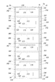
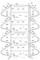
右端部弾性部材15は、図2及び図4に示すように、右端部折り返し部13と着用者側不織布1cとの間に挟まれるようにして、複数個所の接続部(上から右第1接続部151、右第2接続部152、右第3接続部153、右第4接続部154及び右第5接続部155)において、右端部折り返し部13及び着用者側不織布1cに接続されている。
また、左端部弾性部材16は、図2及び図4に示すように、左端部折り返し部14と着用者側不織布1cとの間に挟まれるようにして、複数個所の接続部(上から左第1接続部161、左第2接続部162、左第3接続部163、左第4接続部164及び左第5接続部165)において、左端部折り返し部14及び着用者側不織布1cに接続されている。
また、左端部弾性部材16は、図2及び図4に示すように、左端部折り返し部14と着用者側不織布1cとの間に挟まれるようにして、複数個所の接続部(上から左第1接続部161、左第2接続部162、左第3接続部163、左第4接続部164及び左第5接続部165)において、左端部折り返し部14及び着用者側不織布1cに接続されている。
また、図2に示すように、各接続部は、プリーツを避け、上下方向においてこれらの間となる位置(右第1接続部151及び左第1接続部161については、マスク本体部1の上端部と第1プリーツ111との間、右第2接続部152及び左第2接続部162については、第1プリーツ111と第2プリーツ112との間、右第3接続部153及び左第3接続部163については、第2プリーツ112と第3プリーツ113との間、右第4接続部154及び左第4接続部164については、第3プリーツ113と第4プリーツ114との間、右第5接続部155及び左第5接続部165については、第4プリーツ114とマスク本体部1の下端部との間)に形成されている。
(鼻部補強部材)
鼻部補強部材171は、マスク本体部1の上部が着用者の鼻付近の形状に沿って、隙間が生じないようにするためのものであり、図1から図3に示すように、マスク本体部1の上端縁に沿って備えられている。
鼻部補強部材171は、左右方向に長い可塑性を有する部材であり、マスク本体部1の横幅よりも短く、左右方向に、好ましくは80から135mm、さらに好ましくは90mmから120mmの長さを有し、上下方向に、好ましくは幅3mmから5mm、前後方向に好ましくは厚み0.5mmから1.0mmとなるように形成されている。
鼻部補強部材171は、マスク本体部1の上部が着用者の鼻付近の形状に沿って、隙間が生じないようにするためのものであり、図1から図3に示すように、マスク本体部1の上端縁に沿って備えられている。
鼻部補強部材171は、左右方向に長い可塑性を有する部材であり、マスク本体部1の横幅よりも短く、左右方向に、好ましくは80から135mm、さらに好ましくは90mmから120mmの長さを有し、上下方向に、好ましくは幅3mmから5mm、前後方向に好ましくは厚み0.5mmから1.0mmとなるように形成されている。
鼻部補強部材171の材料としては、可塑性を有する任意の材料を使用可能であるが、例えば、ポリプロピレン樹脂、ポリエチレン樹脂、ポリエステル樹脂等が用いられ、最も好適には、ポリプロピレン樹脂が用いられる。
鼻部補強部材171は、図3に示すように、フィルター1bと着用者側不織布1cとの間に配置され、図1から図3に示すように、外面側不織布1a、フィルター1b及び着用者側不織布1cを、鼻部補強部材171の上下及び左右において熱・超音波等を用いて前後に溶着させることで、鼻部補強部材171を囲むように形成された鼻部補強部材周辺接合部125によって、マスク本体部1に取り付けられている。
なお、鼻部補強部材171の配置及び取り付け方法はこれに限られず、例えば外面側不織布1aとフィルター1bとの間に配置されていてもよい。
なお、鼻部補強部材171の配置及び取り付け方法はこれに限られず、例えば外面側不織布1aとフィルター1bとの間に配置されていてもよい。
(口部補強部材)
口部補強部材172は、マスク本体部1の着用者の口元付近の形状を維持するための部材であり、図1から図4に示すように、マスク本体部1の、第2プリーツ112と第3プリーツ113との間の位置の、マスク本体部1の上下方向中央部付近に取り付けられている。
口部補強部材172は、マスク本体部1の着用者の口元付近の形状を維持するための部材であり、図1から図4に示すように、マスク本体部1の、第2プリーツ112と第3プリーツ113との間の位置の、マスク本体部1の上下方向中央部付近に取り付けられている。
口部補強部材172は、左右方向に長い可塑性を有する部材であり、マスク本体部1の横幅よりも僅かに短く、左右方向に、好ましくは100から150mm、さらに好ましくは115mmから145mmの長さを有し、上下方向に、好ましくは幅3mmから5mm、前後方向に好ましくは厚み0.5mmから1.0mmとなるように形成されている。
口部補強部材172の材料としては、可塑性を有する任意の材料を使用可能であるが、例えば、鼻部補強部材171と同様、ポリプロピレン樹脂、ポリエチレン樹脂、ポリエステル樹脂等が用いられ、最も好適には、ポリプロピレン樹脂が用いられる。
口部補強部材172は、図3及び図4に示すように、フィルター1bと着用者側不織布1cとの間に配置され、図1から図4に示すように、外面側不織布1a、フィルター1b及び着用者側不織布1cを、口部補強部材172の上下及び左右において、熱・超音波等を用いて前後に溶着させることで、口部補強部材172を囲むように形成された口部補強部材周辺接合部126によって、マスク本体部1に取り付けられている。
なお、口部補強部材172の配置及び取り付け方法はこれに限られず、例えば外面側不織布1aとフィルター1bとの間に配置されていてもよい。
なお、口部補強部材172の配置及び取り付け方法はこれに限られず、例えば外面側不織布1aとフィルター1bとの間に配置されていてもよい。
(耳掛け部)
右耳掛け部2及び左耳掛け部3は、いずれもポリウレタン等の伸縮性を有する材料によって形成された紐状の部材を、マスク本体部1に取り付けることによって形成されている。
具体的には、図1及び図2に示すように、右耳掛け部2はマスク本体部1の右側において、紐状の部材の一方の端部がマスク本体部1の後面側右上端部付近(右端部折り返し部13の上部)に熱・超音波等によって溶着され、他方の端部がマスク本体部1の後面側右下端部付近(右端部折り返し部13の下部)に熱・超音波等によって溶着されるようにして形成されている。また左耳掛け部3はマスク本体部1の左側において、紐状の部材の一方の端部がマスク本体部1の後面側左上端部付近(左端部折り返し部14の上部)に熱・超音波等によって溶着され、他方の端部がマスク本体部1の後面側左下端部付近(左端部折り返し部14の下部)に熱・超音波等によって溶着されるようにして形成されている。
右耳掛け部2及び左耳掛け部3は、いずれも一端部から他端部までの長さが、好ましくは140mmから200mm、さらに好ましくは160mmから180mmとなるように形成される。
右耳掛け部2及び左耳掛け部3は、いずれもポリウレタン等の伸縮性を有する材料によって形成された紐状の部材を、マスク本体部1に取り付けることによって形成されている。
具体的には、図1及び図2に示すように、右耳掛け部2はマスク本体部1の右側において、紐状の部材の一方の端部がマスク本体部1の後面側右上端部付近(右端部折り返し部13の上部)に熱・超音波等によって溶着され、他方の端部がマスク本体部1の後面側右下端部付近(右端部折り返し部13の下部)に熱・超音波等によって溶着されるようにして形成されている。また左耳掛け部3はマスク本体部1の左側において、紐状の部材の一方の端部がマスク本体部1の後面側左上端部付近(左端部折り返し部14の上部)に熱・超音波等によって溶着され、他方の端部がマスク本体部1の後面側左下端部付近(左端部折り返し部14の下部)に熱・超音波等によって溶着されるようにして形成されている。
右耳掛け部2及び左耳掛け部3は、いずれも一端部から他端部までの長さが、好ましくは140mmから200mm、さらに好ましくは160mmから180mmとなるように形成される。
{マスクの製造方法}
次に、第1実施形態に係るマスク100の製造方法について、図5から図10に基づいて説明する。マスク100の製造方法は、第1工程から第7工程の7つの工程からなる。
次に、第1実施形態に係るマスク100の製造方法について、図5から図10に基づいて説明する。マスク100の製造方法は、第1工程から第7工程の7つの工程からなる。
(第1工程)
第1工程は、マスク本体部1を構成するシート材の積層工程である。
第1工程は、マスク本体部1を構成するシート材の積層工程である。
具体的には、外面側不織布1a、フィルター1b、着用者側不織布1cのそれぞれを形成するシート材につき、長尺なシート材がロール状に巻かれたシートロール(外面側不織布1aが巻かれたものをシートロールR1、フィルター1bが巻かれたものをシートロールR2、着用者側不織布1cが巻かれたものをシートロールR3という。)とした上で、図5に示すように、各シートロールからそれぞれのシート材を繰り出しつつ、これらを下から外面側不織布1a、フィルター1b、着用者側不織布1cの順に積層する。
この際、ロールシートR2及びR3については、巻かれたフィルター1b及び着用者側不織布1cの幅(短手方向の長さ)が、製造するマスク本体部1の左右方向の幅と一致するように形成し、ロールシートR1については、巻かれた外面側不織布1aの幅が、製造するマスク本体部1の左右方向の幅に、右端部折り返し部13及び左端部折り返し部14の幅を加えた長さと一致するように形成しておき、図6に示すように、上方から見た際に、フィルター1bと着用者側不織布1cの略全体が重なると共に、外面側不織布1aの両端部が等間隔ではみ出すようにして積層する。
また、この際には、図6に示すように、鼻部補強部材171及び口部補強部材172を、着用者側不織布1cとフィルター1bとの間の所定の位置に、その長手方向が、各シート材の繰り出し方向と直行する方向(図6におけるシート材の短手方向)と一致するようにして配置する。
(第2工程)
第2工程は、上端部接合部121、下端部接合部122、鼻部補強部材周辺接合部125及び口部補強部材周辺接合部126の形成工程である。
第2工程は、上端部接合部121、下端部接合部122、鼻部補強部材周辺接合部125及び口部補強部材周辺接合部126の形成工程である。
具体的には、図7に示すように、上記のように積層された外面側不織布1a、フィルター1b及び着用者側不織布1cにつき、後の第7工程の切断後におけるマスク本体部1の上端部に沿って、各シート材の繰り出し方向と直行する直線状に接合することで、上端部接合部121を形成する。
また、図7に示すように、上記のように積層された外面側不織布1a、フィルター1b及び着用者側不織布1cにつき、後の第7工程の切断後におけるマスク本体部1の下端部に沿って、各シート材の繰り出し方向と直行する直線状に接合することで、下端部接合部122を形成する。
また、図7に示すように、上記のように積層された外面側不織布1a、フィルター1b及び着用者側不織布1cにつき、後の第7工程の切断後におけるマスク本体部1の下端部に沿って、各シート材の繰り出し方向と直行する直線状に接合することで、下端部接合部122を形成する。
さらに、図7に示すように、上記のように積層された外面側不織布1a、フィルター1b及び着用者側不織布1cにつき、鼻部補強部材171及び口部補強部材172を囲むように接合することで、鼻部補強部材周辺接合部125及び口部補強部材周辺接合部126を形成する。
具体的なシート材の接合方法としては、いずれについても、例えば、熱・超音波等を用いてシート材を溶着させればよい。
具体的なシート材の接合方法としては、いずれについても、例えば、熱・超音波等を用いてシート材を溶着させればよい。
(第3工程)
第3工程は、右端部弾性部材15及び左端部弾性部材16の取り付け工程である。
第3工程は、右端部弾性部材15及び左端部弾性部材16の取り付け工程である。
具体的には、図8に示すように、右端部弾性部材15については、マスク本体部1の上下方向の長さ複数枚分の長さを有する右端部弾性部材15つき、これを引き伸ばした状態で、作製するマスク本体部1それぞれの右第1接続部151、右第2接続部152、右第3接続部153、右第4接続部154及び右第5接続部155となる位置において、右端部折り返し部13となる外面側不織布1aのはみ出し部分に接続する。
また、左端部弾性部材16については、マスク本体部1の上下方向の長さ複数枚分の長さを有する左端部弾性部材16つき、これを引きのばした状態で、作製するマスク本体部1それぞれの左第1接続部161、左第2接続部162、左第3接続部163、左第4接続部164及び左第5接続部165となる位置において、左端部折り返し部14となる外面側不織布1aのはみ出し部分に接続する。
具体的な接続方法としては、例えば、所定の糊・ホットメルト接着剤等を用いて接着すればよい。
また、左端部弾性部材16については、マスク本体部1の上下方向の長さ複数枚分の長さを有する左端部弾性部材16つき、これを引きのばした状態で、作製するマスク本体部1それぞれの左第1接続部161、左第2接続部162、左第3接続部163、左第4接続部164及び左第5接続部165となる位置において、左端部折り返し部14となる外面側不織布1aのはみ出し部分に接続する。
具体的な接続方法としては、例えば、所定の糊・ホットメルト接着剤等を用いて接着すればよい。
なお、具体的な接続部の形成数及び形成位置は、図8に示したものに限られず、適宜変更可能である。後述のように、プリーツは、上下方向において接続部の間となる位置に形成されることから、これによって、後述の第7工程において形成されるプリーツの数及び位置を調整できる。
右端部弾性部材15及び左端部弾性部材16としては、上記のように、例えば、太さ470dtexから1200dtexのスパンデックスを、右端部弾性部材15及び左端部弾性部材16のそれぞれについて3本から10本使用することが好ましい。また、右端部弾性部材15及び左端部弾性部材16共に、これを元の長さの150%から250%に伸ばした状態で取り付けることが望ましい。
なお、後述の第6工程までは、シート材の繰り出し方向(図8におけるシート材の長手方向)へと各シート材が引っ張られ、テンションが掛かった状態で行う。したがって、右端部弾性部材15及び左端部弾性部材16を引き伸ばした状態で取り付けたとしても、この段階では、マスク本体部1を形成するシート材が収縮することはない。
(第4工程)
第4工程は、右端部折り返し部13及び左端部折り返し部14の形成工程である。
第4工程は、右端部折り返し部13及び左端部折り返し部14の形成工程である。
具体的には、図9に示すように、外面側不織布1aの両端部のはみ出し部分につき、フィルター1b及び着用者側不織布1cの端部を覆うようにして着用者側不織布1c側へと折り返すことで、右端部折り返し部13及び左端部折り返し部14を形成する。
この際には、図8に示すように、着用者側不織布1cの、右第1接続部151、右第2接続部152、右第3接続部153、右第4接続部154及び右第5接続部155並びに左第1接続部161、左第2接続部162、左第3接続部163、左第4接続部164及び左第5接続部165に対応する位置にも、例えば、所定の糊・ホットメルト接着剤等を塗布しておくことで、右端部弾性部材15及び左端部弾性部材16が、各接続部において、着用者側不織布1cにも接着されるようにすることが好ましい。これによって、右端部弾性部材15及び左端部弾性部材16の取り付けが強固になる。
ただし、これは必須ではなく、右端部弾性部材15及び左端部弾性部材16は、右端部折り返し部13又は左端部折り返し部14のみに接着されていてもよい。
ただし、これは必須ではなく、右端部弾性部材15及び左端部弾性部材16は、右端部折り返し部13又は左端部折り返し部14のみに接着されていてもよい。
(第5工程)
第5工程は、右端部接合部123及び左端部接合部124の形成工程である。
第5工程は、右端部接合部123及び左端部接合部124の形成工程である。
具体的には、図9に示すように、折り返された右端部折り返し部13の左端部(マスク本体部1中央よりの端部)近傍において、下から外面側不織布1a、フィルター1b、着用者側不織布1c及び右端部折り返し部13を形成する外面側不織布1aの4層に重なったシート材につき、各シート材の繰り出し方向と平行な直線状に接合することで、右端部接合部123を形成する。
また、折り返された左端部折り返し部14の右端部(マスク本体部1中央よりの端部)近傍において、外面側不織布1a、フィルター1b、着用者側不織布1c及び左端部折り返し部14を形成する外面側不織布1aの4層に重なったシート材につき、各シート材の繰り出し方向と平行な直線状に接合することで、左端部接合部124を形成する。
具体的なシート材の接合方法としては、ここでも、例えば、熱・超音波等を用いて溶着させればよい。
また、折り返された左端部折り返し部14の右端部(マスク本体部1中央よりの端部)近傍において、外面側不織布1a、フィルター1b、着用者側不織布1c及び左端部折り返し部14を形成する外面側不織布1aの4層に重なったシート材につき、各シート材の繰り出し方向と平行な直線状に接合することで、左端部接合部124を形成する。
具体的なシート材の接合方法としては、ここでも、例えば、熱・超音波等を用いて溶着させればよい。
(第6工程)
第6工程は、耳掛け部の形成工程である。
第6工程は、耳掛け部の形成工程である。
具体的には、図10に示すように、ポリウレタン等の伸縮性を有する材料によって形成された連続した紐状の部材を各シート材の繰り出し方向と直行する方向の両端部に取り付けることによって、右耳掛け部2及び左耳掛け部3を形成する。
この際には、右耳掛け部2は、図10に示すように、連続した紐状の部材を、それぞれのマスク本体部1において右端部折り返し部13の上部及び右端部折り返し部13の下部となる位置に、例えば熱・超音波等によって溶着させることによって形成する。
また、左耳掛け部3は、図10に示すように、連続した紐状の部材を、それぞれのマスク本体部1において左端部折り返し部14の上部及び左端部折り返し部14の下部となる位置に、例えば熱・超音波等によって溶着させることによって形成する。
なお、連続して形成された右耳掛け部2及び左耳掛け部3は、第7工程においてマスク本体部1と共に切り離されることとなる。
この際には、右耳掛け部2は、図10に示すように、連続した紐状の部材を、それぞれのマスク本体部1において右端部折り返し部13の上部及び右端部折り返し部13の下部となる位置に、例えば熱・超音波等によって溶着させることによって形成する。
また、左耳掛け部3は、図10に示すように、連続した紐状の部材を、それぞれのマスク本体部1において左端部折り返し部14の上部及び左端部折り返し部14の下部となる位置に、例えば熱・超音波等によって溶着させることによって形成する。
なお、連続して形成された右耳掛け部2及び左耳掛け部3は、第7工程においてマスク本体部1と共に切り離されることとなる。
(第7工程)
第7工程は、マスク本体部1を形成するシート材の切断工程である。本工程によって、連なって形成されていたマスク本体部1が1枚ずつに分離される。
第7工程は、マスク本体部1を形成するシート材の切断工程である。本工程によって、連なって形成されていたマスク本体部1が1枚ずつに分離される。
具体的には、一のマスク本体部1の下端部接合部122と、これに続いて形成された他のマスク本体部1の上端部接合部121との間に位置する所定の切断位置において、シート材の繰り出し方向と直行する直線状に切断することで、マスク本体部1のそれぞれを分離する。この際には、第6工程において紐状の部材が連続して取り付けられて形成されていた右耳掛け部2及び左耳掛け部3も、それぞれのマスク本体部1毎に切り取られ、分離されることとなる。
上記のように、第6工程までは、各シート材の繰り出し方向(図6から図10におけるシート材の長手方向)へと各シート材が引っ張られ、テンションが掛かった状態で行われることから、右端部弾性部材15及び左端部弾性部材16を引き伸ばした状態で取り付けても、マスク本体部1を形成するシート材が収縮することはない。
しかし第7工程において、シート材が切断され、マスク本体部1が1枚ずつに分離されると、上記のテンションが掛からなくなる。
そうすると、第3工程において引き伸ばされた状態で取り付けられた右端部弾性部材15及び左端部弾性部材16が収縮し、これに伴って、マスク本体部1が各シート材の繰り出し方向(マスク100の使用時における上下方向)に収縮することとなる。
しかし第7工程において、シート材が切断され、マスク本体部1が1枚ずつに分離されると、上記のテンションが掛からなくなる。
そうすると、第3工程において引き伸ばされた状態で取り付けられた右端部弾性部材15及び左端部弾性部材16が収縮し、これに伴って、マスク本体部1が各シート材の繰り出し方向(マスク100の使用時における上下方向)に収縮することとなる。
この際には、上記の通り、右端部弾性部材15は、右第1接続部151、右第2接続部152、右第3接続部153、右第4接続部154及び右第5接続部155の5か所において、マスク本体部1を形成するシート材(右端部折り返し部13及び着用者側不織布1c)に接続され、左端部弾性部材16は、左第1接続部161、左第2接続部162、左第3接続部163、左第4接続部164及び左第5接続部165の5か所において、マスク本体部1を形成するシート材(左端部折り返し部14及び着用者側不織布1c)に接続されていることから、右端部弾性部材15及び左端部弾性部材16は、これら接続部を引っ張り、これらの間隔を縮めるようにして収縮する。
またこの際には。右端部弾性部材15及び左端部弾性部材16は、マスク本体部1の後面側(着用者側不織布1c側)に備えられているため、マスク本体部1を形成する各シート材は、各接続部の間となる位置において、図3に示すように、前方側(外面側不織布1a側)へと突出するようにして収縮することとなる。
これによって、図2に示すように、右第1接続部151と右第2接続部152との間及び左第1接続部161と左第2接続部162との間を通るようにして第1プリーツ111が形成され、右第2接続部152と右第3接続部153との間及び左第2接続部162と左第3接続部163との間を通るようにして第2プリーツ112が形成され、右第3接続部153と右第4接続部154との間及び左第3接続部163と左第4接続部164との間を通るようにして第3プリーツ113が形成され、右第4接続部154と右第5接続部155との間及び左第4接続部164と左第5接続部165との間を通るようにして第4プリーツ114が形成される。
これによって、図2に示すように、右第1接続部151と右第2接続部152との間及び左第1接続部161と左第2接続部162との間を通るようにして第1プリーツ111が形成され、右第2接続部152と右第3接続部153との間及び左第2接続部162と左第3接続部163との間を通るようにして第2プリーツ112が形成され、右第3接続部153と右第4接続部154との間及び左第3接続部163と左第4接続部164との間を通るようにして第3プリーツ113が形成され、右第4接続部154と右第5接続部155との間及び左第4接続部164と左第5接続部165との間を通るようにして第4プリーツ114が形成される。
{効果の説明}
第1実施形態に係るマスク100及びその製造方法によれば、上記のように、製造過程においてマスク本体部1を形成するシート材を回転させることを要せず、これを一定方向に流しつつ、一連の流れでプリーツ型のマスクを製造することができる。
したがって、マスクの製造効率を向上することが可能となる。
第1実施形態に係るマスク100及びその製造方法によれば、上記のように、製造過程においてマスク本体部1を形成するシート材を回転させることを要せず、これを一定方向に流しつつ、一連の流れでプリーツ型のマスクを製造することができる。
したがって、マスクの製造効率を向上することが可能となる。
また、上記のように、製造されたマスク100において、右端部弾性部材15及び左端部弾性部材16は、右端部折り返し部13又は左端部折り返し部14によって覆われていることから、右端部弾性部材15及び左端部弾性部材16を備えたことによって、マスクの外観および装着感を損ねることも防止できる。
また、マスク本体部1の左右の端部に、上下方向に延在するようにして右端部弾性部材15及び左端部弾性部材16が備えられていることによって、マスク100の着用時における、マスク本体部1左右の密閉性も改善することができる。
[第2実施形態]
第2実施形態に係るマスク100Aの構成及び製造方法につき、以下説明する。なお、第1実施形態に係るマスク100と同一の部分については、同一の符号を付して説明を省略する。
第2実施形態に係るマスク100Aの構成及び製造方法につき、以下説明する。なお、第1実施形態に係るマスク100と同一の部分については、同一の符号を付して説明を省略する。
{マスクの構成}
まず、第2実施形態に係るマスク100Aの構成について、図11から図13に基づいて説明する。
なお、本実施形態についても、図11に示すように、マスクを着用者が着用した状態において、当該着用者から見た方向を基準として、前後、左右及び上下を定めて説明する。
まず、第2実施形態に係るマスク100Aの構成について、図11から図13に基づいて説明する。
なお、本実施形態についても、図11に示すように、マスクを着用者が着用した状態において、当該着用者から見た方向を基準として、前後、左右及び上下を定めて説明する。
第2実施形態に係るマスク100Aは、マスク本体部1Aにつき、右端部折り返し部13及び左端部折り返し部14を形成せず、図11から図13に示すように、代わりに、外面側不織布1a、フィルター1b及び着用者側不織布1cとは別個のシート材によって形成された右ギャザーシート18及び左ギャザーシート19を備えたものである。また、右端部弾性部材15は右ギャザーシート18に備えられ、左端部弾性部材16は、左ギャザーシート19に備えられている。
(ギャザーシート)
右ギャザーシート18及び左ギャザーシート19は、上下方向にマスク本体部1を形成する外面側不織布1a、フィルター1b及び着用者側不織布1cと同様の長さを有するシート材につき、図13に示すようにZ字状の断面形状となるように折り畳むことによって形成されている。これによって、図13に示すように、右ギャザーシート18には、第1面部181、第2面部182及び第3面部183が形成され、左ギャザーシート19には、第1面部191、第2面部192及び第3面部193が形成されている。
右ギャザーシート18及び左ギャザーシート19は、上下方向にマスク本体部1を形成する外面側不織布1a、フィルター1b及び着用者側不織布1cと同様の長さを有するシート材につき、図13に示すようにZ字状の断面形状となるように折り畳むことによって形成されている。これによって、図13に示すように、右ギャザーシート18には、第1面部181、第2面部182及び第3面部183が形成され、左ギャザーシート19には、第1面部191、第2面部192及び第3面部193が形成されている。
右ギャザーシート18及び左ギャザーシート19を形成するシート材の種類は特に限定されないが、例えば、着用者側不織布1cと同一のシート材を用いればよい。また、右ギャザーシート18及び左ギャザーシート19は、いずれも第1面部、第2面部及び第3面部の幅が略等しく、第1面部、第2面部及び第3面部の幅がそれぞれ8mmから18mmとなるように形成されることが好ましい。
図13に示すように、右ギャザーシート18は、第1面部181の、第2面部182と接続されていない側の端部が、マスク本体部1の右端部と一致するようにして、着用者側不織布1cに接続されている。
また、左ギャザーシート19は、第1面部191の、第2面部192と接続されていない側の端部が、マスク本体部1の左端部と一致するようにして、着用者側不織布1cに接続されている。
また、左ギャザーシート19は、第1面部191の、第2面部192と接続されていない側の端部が、マスク本体部1の左端部と一致するようにして、着用者側不織布1cに接続されている。
右ギャザーシート18及び左ギャザーシート19は、例えば、第1面部181又は第1面部191の全面を所定の糊・ホットメルト接着剤等を用いて着用者側不織布1cに貼付することによって、着用者側不織布1cと接続されている。
(弾性部材)
右端部弾性部材15は、図13に示すように、右ギャザーシート18に、第2面部182と第3面部183との間に挟まれるようにして備えられ、左端部弾性部材16は、図123に示すように、左ギャザーシート19の第2面部192と第3面部193との間に挟まれるようにして備えられている。
右端部弾性部材15は、図13に示すように、右ギャザーシート18に、第2面部182と第3面部183との間に挟まれるようにして備えられ、左端部弾性部材16は、図123に示すように、左ギャザーシート19の第2面部192と第3面部193との間に挟まれるようにして備えられている。
右端部弾性部材15は、図13に示すように右ギャザーシート18の第2面部182と第3面部183との間に挟まれた状態で、図12に示すように複数個所の接続部(上から右第1接続部151A、右第2接続部152A、右第3接続部153A、右第4接続部154A及び右第5接続部155A)において、図13に示すように第2面部182及び第3面部183の両者に接続されている。
また、左端部弾性部材16は、図13に示すように左ギャザーシート19の第2面部192と第3面部193との間に挟まれた状態で、図12に示すように複数個所の接続部(上から左第1接続部161A、左第2接続部162A、左第3接続部163A、左第4接続部164A及び左第5接続部165A)において、図13に示すように第2面部192及び第3面部193の両者に接続されている。
また、左端部弾性部材16は、図13に示すように左ギャザーシート19の第2面部192と第3面部193との間に挟まれた状態で、図12に示すように複数個所の接続部(上から左第1接続部161A、左第2接続部162A、左第3接続部163A、左第4接続部164A及び左第5接続部165A)において、図13に示すように第2面部192及び第3面部193の両者に接続されている。
図12に示すように、第1実施形態と同様、各接続部は、上下方向において、プリーツを避け、上下方向にこれらの間となる位置(右第1接続部151A及び左第1接続部161Aについては、マスク本体部1Aの上端部と第1プリーツ111との間、右第2接続部152A及び左第2接続部162Aについては、第1プリーツ111と第2プリーツ112との間、右第3接続部153A及び左第3接続部163Aについては、第2プリーツ112と第3プリーツ113との間、右第4接続部154A及び左第4接続部164Aについては、第3プリーツ113と第4プリーツ114との間、右第5接続部155A及び左第5接続部165Aについては、第4プリーツ114とマスク本体部1Aの下端部との間)に形成されている。
(耳掛け部)
右耳掛け部2及び左耳掛け部3は、第1実施形態と同様に、いずれもポリウレタン等の伸縮性を有する材料によって形成された紐状の部材をマスク本体部1に取り付けることによって形成されている。
右耳掛け部2及び左耳掛け部3は、第1実施形態と同様に、いずれもポリウレタン等の伸縮性を有する材料によって形成された紐状の部材をマスク本体部1に取り付けることによって形成されている。
ただし、第1実施形態とは異なり、右耳掛け部2はマスク本体部1Aの右側において、紐状の部材の一方の端部がマスク本体部1Aの着用者側不織布1cの右上端部付近に熱・超音波等によって溶着され、他方の端部が着用者側不織布1cの右下端部付近に熱・超音波等によって溶着されるようにして、マスク本体部1Aに固定されている。
また左耳掛け部3はマスク本体部1Aの左側において、紐状の部材の一方の端部がマスク本体部1Aの着用者側不織布1cの左上端部付近に熱・超音波等によって溶着され、他方の端部がマスク本体部1Aの着用者側不織布1cの左下端部付近に熱・超音波等によって溶着されるようにして、マスク本体部1Aに固定されている。
また左耳掛け部3はマスク本体部1Aの左側において、紐状の部材の一方の端部がマスク本体部1Aの着用者側不織布1cの左上端部付近に熱・超音波等によって溶着され、他方の端部がマスク本体部1Aの着用者側不織布1cの左下端部付近に熱・超音波等によって溶着されるようにして、マスク本体部1Aに固定されている。
また、右耳掛け部2の着用者側不織布1cへの接続部の上から右ギャザーシート18が取り付けられ、左耳掛け部3の着用者側不織布1cへの接続部の上から左ギャザーシート19が取り付けられることで、右耳掛け部2のマスク本体部1Aへの取付部は着用者側不織布1cと右ギャザーシート18との間に挟まれ、左耳掛け部3のマスク本体部1Aへの取付部は着用者側不織布1cと左ギャザーシート19との間に挟まれている。
これによって、右耳掛け部2及び左耳掛け部3を強固にマスク本体部1Aに固定することができる。
これによって、右耳掛け部2及び左耳掛け部3を強固にマスク本体部1Aに固定することができる。
なお、右耳掛け部2及び左耳掛け部3のマスク本体部1Aへの固定方法は上記のものに限られず、例えば、その両端部を外面側不織布1aとフィルター1bとの間、又はフィルター1bと着用者側不織布1cとの間に挟み込んだ状態で後述の右端部接合部123A及び左端部接合部124Aを形成することによって、右端部接合部123A及び左端部接合部124Aによって、各シート材を固定すると同時に、右耳掛け部2及び左耳掛け部3をマスク本体部1に固定するようにしてもよい。
(右端部接合部及び左端部接合部)
上記のように、マスク本体部1Aは、右端部折り返し部13及び左端部折り返し部14を備えず、右端部接合部123A及び左端部接合部124Aは、図11及び図13に示すように、外面側不織布1a、フィルター1b及び着用者側不織布1cの3層を、例えば熱・超音波等によって前後に接合するようして、マスク本体部1Aの右端部又は左端部に沿って上下方向に延在する直線状に形成されている。
上記のように、マスク本体部1Aは、右端部折り返し部13及び左端部折り返し部14を備えず、右端部接合部123A及び左端部接合部124Aは、図11及び図13に示すように、外面側不織布1a、フィルター1b及び着用者側不織布1cの3層を、例えば熱・超音波等によって前後に接合するようして、マスク本体部1Aの右端部又は左端部に沿って上下方向に延在する直線状に形成されている。
(その他の構成)
その他の構成については、第1実施形態に係るマスク100と同様である。
その他の構成については、第1実施形態に係るマスク100と同様である。
{マスクの製造方法}
次に、第2実施形態に係るマスク100Aの製造方法について、図14から図18に基づいて説明する。マスク100Aの製造方法は、第1工程から第6工程の6つの工程からなる。なお、第1実施形態に係るマスク100の製造方法と同一の部分については、説明を省略する。
次に、第2実施形態に係るマスク100Aの製造方法について、図14から図18に基づいて説明する。マスク100Aの製造方法は、第1工程から第6工程の6つの工程からなる。なお、第1実施形態に係るマスク100の製造方法と同一の部分については、説明を省略する。
(第1工程)
第1工程は、マスク本体部1を構成するシート材の積層工程である。
第1工程は、マスク本体部1を構成するシート材の積層工程である。
具体的には、第1実施形態と同様、外面側不織布1a、フィルター1b、着用者側不織布1cのそれぞれを形成するシート材につき、長尺なシート材がロール状に巻かれたシートロール(シートロールR1、シートロールR2、シートロールR3)とした上で、図5に示すように、各シートロールからそれぞれのシート材を繰り出しつつ、これらを下から外面側不織布1a、フィルター1b、着用者側不織布1cの順に積層する。
ただし、この際、第2実施形態においては、第1実施形態と異なり、右端部折り返し部13及び左端部折り返し部14は必要ないため、ロールシートR1、R2及びR3について、巻かれた外面側不織布1a、フィルター1b及び着用者側不織布1cの幅が、製造するマスク本体部1の左右方向の幅と一致するように形成しておき、図14に示すように、上方から見た際に、外面側不織布1a、フィルター1b及び着用者側不織布1cの略全体が重なるようにして積層すればよい。
なお、具体的な各シート材の幅は上記に限られず、例えば、第1実施形態と同様にして、右端部折り返し部13及び左端部折り返し部14を形成することも可能である。また、第1実施形態と同様に外面側不織布1aの幅がフィルター1b及び着用者側不織布1cよりも広くなるように形成した上で、右端部折り返し部13及び左端部折り返し部14を形成せず、当該はみ出し部分をそのままの状態で、例えば耳掛け部の固定部分等として活用してもよい。
なお、具体的な各シート材の幅は上記に限られず、例えば、第1実施形態と同様にして、右端部折り返し部13及び左端部折り返し部14を形成することも可能である。また、第1実施形態と同様に外面側不織布1aの幅がフィルター1b及び着用者側不織布1cよりも広くなるように形成した上で、右端部折り返し部13及び左端部折り返し部14を形成せず、当該はみ出し部分をそのままの状態で、例えば耳掛け部の固定部分等として活用してもよい。
また、この際には、第1実施形態と同様、図14に示すように、鼻部補強部材171及び口部補強部材172を、着用者側不織布1cとフィルター1bとの間の所定の位置に、その長手方向が、各シート材の繰り出し方向と直行する方向(図14におけるシート材の短手方向)と一致するようにして配置する。
(第2工程)
第2工程は、上端部接合部121、下端部接合部122、右端部接合部123A、左端部接合部124A、鼻部補強部材周辺接合部125及び口部補強部材周辺接合部126の形成工程である。
第2工程は、上端部接合部121、下端部接合部122、右端部接合部123A、左端部接合部124A、鼻部補強部材周辺接合部125及び口部補強部材周辺接合部126の形成工程である。
具体的には、第1実施形態と同様、図15に示すように、上記のように積層された外面側不織布1a、フィルター1b及び着用者側不織布1cにつき、後の第6工程の切断後におけるマスク本体部1Aの上端部に沿って、各シート材の繰り出し方向と直行する直線状に接合することで、上端部接合部121を形成し、後の第6工程の切断後におけるマスク本体部1の下端部に沿って、各シート材の繰り出し方向と直行する直線状に接合することで、下端部接合部122を形成する。
また、後の第6工程の切断後におけるマスク本体部1Aの右端部に沿って、各シート材の繰り出し方向と平行な直線状に外面側不織布1a、フィルター1b及び着用者側不織布1cを接合することで、右端部接合部123Aを形成し、後の第6工程の切断後におけるマスク本体部1Aの左端部に沿って、各シート材の繰り出し方向と平行な直線状に外面側不織布1a、フィルター1b及び着用者側不織布1cを接合することで、左端部接合部124Aを形成する。
さらに、図15に示すように、外面側不織布1a、フィルター1b及び着用者側不織布1cにつき、鼻部補強部材171及び口部補強部材172を囲むように接合することで、鼻部補強部材周辺接合部125及び口部補強部材周辺接合部126を形成する。
また、後の第6工程の切断後におけるマスク本体部1Aの右端部に沿って、各シート材の繰り出し方向と平行な直線状に外面側不織布1a、フィルター1b及び着用者側不織布1cを接合することで、右端部接合部123Aを形成し、後の第6工程の切断後におけるマスク本体部1Aの左端部に沿って、各シート材の繰り出し方向と平行な直線状に外面側不織布1a、フィルター1b及び着用者側不織布1cを接合することで、左端部接合部124Aを形成する。
さらに、図15に示すように、外面側不織布1a、フィルター1b及び着用者側不織布1cにつき、鼻部補強部材171及び口部補強部材172を囲むように接合することで、鼻部補強部材周辺接合部125及び口部補強部材周辺接合部126を形成する。
(第3工程)
第3工程は、耳掛け部の形成工程である。
第3工程は、耳掛け部の形成工程である。
具体的には、図16に示すように、ポリウレタン等の伸縮性を有する材料によって形成された連続した紐状の部材を、各シート材の繰り出し方向と直行する方向の両端部に取り付けることによって、右耳掛け部2及び左耳掛け部3を形成する。
この際には、右耳掛け部2は、図16に示すように、連続した紐状の部材を、それぞれのマスク本体部1において、マスク本体部1後面側(着用者側不織布1c側)の右上端部付近及びマスク本体部1後面側(着用者側不織布1c側)の右下端部付近となる位置に、例えば熱・超音波等によって溶着させることによって形成する。
また、左耳掛け部3は、図16に示すように、連続した紐状の部材を、それぞれのマスク本体部1において、マスク本体部1後面側(着用者側不織布1c側)の左上端部付近及びマスク本体部1後面側(着用者側不織布1c側)の左下端部付近となる位置に、例えば熱・超音波等によって溶着させることによって形成する。
なお、連続して形成された右耳掛け部2及び左耳掛け部3は、第6工程においてマスク本体部1Aと共に切り離されることとなる。
この際には、右耳掛け部2は、図16に示すように、連続した紐状の部材を、それぞれのマスク本体部1において、マスク本体部1後面側(着用者側不織布1c側)の右上端部付近及びマスク本体部1後面側(着用者側不織布1c側)の右下端部付近となる位置に、例えば熱・超音波等によって溶着させることによって形成する。
また、左耳掛け部3は、図16に示すように、連続した紐状の部材を、それぞれのマスク本体部1において、マスク本体部1後面側(着用者側不織布1c側)の左上端部付近及びマスク本体部1後面側(着用者側不織布1c側)の左下端部付近となる位置に、例えば熱・超音波等によって溶着させることによって形成する。
なお、連続して形成された右耳掛け部2及び左耳掛け部3は、第6工程においてマスク本体部1Aと共に切り離されることとなる。
なお、右耳掛け部2及び左耳掛け部3の取り付け方法はこれに限られず、例えば、第1工程において、外面側不織布1aとフィルター1bとの間又はフィルター1bと着用者側不織布1cとの間に両端部が挟み込まれるようにポリウレタン等の伸縮性を有する材料によって形成された紐状の部材を配置した上で、これを含めて接合するようにして、第2工程で右端部接合部123A及び左端部接合部124Aを形成することによって、マスク本体部1Aに接合されていてもよい。
(第4工程)
第4工程は、右ギャザーシート18及び左ギャザーシート19の形成工程である。
第4工程は、右ギャザーシート18及び左ギャザーシート19の形成工程である。
具体的には、まず、短手方向に右ギャザーシート18の第1面部181、第2面部182及び第3面部183の幅を合わせた幅を有する長尺なシート材、及び短手方向に左ギャザーシート19の第1面部191、第2面部192及び第3面部193の幅を合わせた幅を有する長尺なシート材につき、短手方向に3等分されるように折り畳むことで、第1面部181、第2面部182及び第3面部183を有する右ギャザーシート18及び第1面部191、第2面部192及び第3面部193を有する左ギャザーシート19を形成する。
これを、右ギャザーシート18は、図13に示すように、第1面部181の、第2面部182と接続されていない側の端部が、マスク本体部1の右端部と一致するようにして、図17に示すように着用者側不織布1cに接続する。
また、左ギャザーシート19は、図13に示すように、第1面部191の、第2面部192と接続されていない側の端部が、マスク本体部1の左端部と一致するようにして、図17に示すように着用者側不織布1cに接続する。
また、左ギャザーシート19は、図13に示すように、第1面部191の、第2面部192と接続されていない側の端部が、マスク本体部1の左端部と一致するようにして、図17に示すように着用者側不織布1cに接続する。
なお、この際には、右ギャザーシート18は、右耳掛け部2の両端部の接続部を着用者側不織布1cとの間に挟み込み、左ギャザーシート19は、左耳掛け部3の両端部の接続部を着用者側不織布1cとの間に挟み込むように取り付ける。
これによって、右耳掛け部2及び左耳掛け部3のマスク本体部1への固定が強固になると共に、右耳掛け部2及び左耳掛け部3のマスク本体部1への接続部が、右ギャザーシート18又は左ギャザーシート19によって覆われることから、マスクの装着感も向上できる。
これによって、右耳掛け部2及び左耳掛け部3のマスク本体部1への固定が強固になると共に、右耳掛け部2及び左耳掛け部3のマスク本体部1への接続部が、右ギャザーシート18又は左ギャザーシート19によって覆われることから、マスクの装着感も向上できる。
右ギャザーシート18及び左ギャザーシート19は、例えば、第1面部181又は第1面部191の全面を、所定の糊・ホットメルト接着剤等を用いて貼付することによって、着用者側不織布1cに取り付ける。
(第5工程)
第5工程は、右端部弾性部材15及び左端部弾性部材16の取り付け工程である。
第5工程は、右端部弾性部材15及び左端部弾性部材16の取り付け工程である。
具体的には、右端部弾性部材15は、これを引き伸ばした状態で、図13に示すように右ギャザーシート18の第2面部182と第3面部183との間に挟み込むようにして、第2面部182及び第3面部183の両者に取り付け、左端部弾性部材16は、これを引き伸ばした状態で、図13に示すように左ギャザーシート19の第2面部192と第3面部193との間に挟み込むようにして、第2面部192及び第3面部193の両者に取り付ける。
この際には、第1実施形態と同様に、太さ470dtexから1200dtexのスパンデックスを、右端部弾性部材15及び左端部弾性部材16のそれぞれに3本から10本使用することが好ましく、また、右端部弾性部材15及び左端部弾性部材16共に、これを元の長さの150%から250%に伸ばした状態で取り付けることが望ましい。
この際には、第1実施形態と同様に、太さ470dtexから1200dtexのスパンデックスを、右端部弾性部材15及び左端部弾性部材16のそれぞれに3本から10本使用することが好ましく、また、右端部弾性部材15及び左端部弾性部材16共に、これを元の長さの150%から250%に伸ばした状態で取り付けることが望ましい。
また、この際には、図18に示すように、右端部弾性部材15については、マスク本体部1Aの上下方向の長さ複数枚分の長さを有する右端部弾性部材15つき、これを引き伸ばした状態で、作製するマスク本体部1Aそれぞれの右第1接続部151A、右第2接続部152A、右第3接続部153A、右第4接続部154A及び右第5接続部155Aとなる位置において、第2面部182及び第3面部183に接続する。
また、左端部弾性部材16については、マスク本体部1Aの上下方向の長さ複数枚分の長さを有する左端部弾性部材16つき、これを引き伸ばした状態で、作製するマスク本体部1Aそれぞれの左第1接続部161A、左第2接続部162A、左第3接続部163A、左第4接続部164A及び左第5接続部165Aとなる位置において、第2面部192及び第3面部193に接続する。
具体的には接続方法としては、例えば、所定の糊・ホットメルト接着剤等を用いて接着すればよい。
また、左端部弾性部材16については、マスク本体部1Aの上下方向の長さ複数枚分の長さを有する左端部弾性部材16つき、これを引き伸ばした状態で、作製するマスク本体部1Aそれぞれの左第1接続部161A、左第2接続部162A、左第3接続部163A、左第4接続部164A及び左第5接続部165Aとなる位置において、第2面部192及び第3面部193に接続する。
具体的には接続方法としては、例えば、所定の糊・ホットメルト接着剤等を用いて接着すればよい。
なお、第1実施形態と同様、具体的な接続部の形成数及び形成位置は、図18に示したものに限られず、適宜変更可能である。後述のように、プリーツは、上下方向において接続部の間となる位置に形成されることから、これによって、後述の第6工程において形成されるプリーツの数及び位置を調整できる。
また、第4工程及び第5工程は、上記の順序には限られず、右端部弾性部材15を右ギャザーシート18に取り付けた後に右ギャザーシート18を着用者側不織布1cに取り付け、また、左端部弾性部材16を左ギャザーシート19に取り付けた後に左ギャザーシート19を着用者側不織布1cに取り付けるようにしてもよい。
第2実施形態においても、第5工程までは、シート材の繰り出し方向(図18におけるシート材の長手方向)へと各シート材が引っ張られ、テンションが掛かった状態で行う。したがって、右端部弾性部材15及び左端部弾性部材16を引き伸ばした状態で取り付けたとしても、この段階では、マスク本体部1を形成するシート材が収縮することはない。
(第6工程)
第6工程は、マスク本体部1Aを形成するシート材の切断工程である。本工程によって、連なって形成されていたマスク本体部1Aが1枚ずつに分離される。
第6工程は、マスク本体部1Aを形成するシート材の切断工程である。本工程によって、連なって形成されていたマスク本体部1Aが1枚ずつに分離される。
具体的には、一のマスク本体部1Aの下端部接合部122と、これに続いて形成された他のマスク本体部1Aの上端部接合部121との間に位置する所定の切断位置において、シート材の繰り出し方向と直行する直線状に切断することで、マスク本体部1Aのそれぞれを分離する。この際には、第3工程において紐状の部材が連続して取り付けられて形成されていた右耳掛け部2及び左耳掛け部3も、それぞれのマスク本体部1A毎に切り取られ、分離されることとなる。
上記のように、第5工程までは、各シート材の繰り出し方向(図14から図18におけるシート材の長手方向)へと各シート材が引っ張られ、テンションが掛かった状態で行われることから、右端部弾性部材15及び左端部弾性部材16を引き伸ばした状態で取り付けても、マスク本体部1Aを形成するシート材が収縮することはない。
しかし、第1実施形態と同様、第6工程においてシート材が切断され、マスク本体部1Aが1枚ずつに分離されると、上記のテンションが掛からなくなることで、第5工程において引き伸ばされた状態で取り付けられた右端部弾性部材15及び左端部弾性部材16が収縮し、これに伴って、マスク本体部1Aが各シート材の繰り出し方向(マスク100Aの使用時における上下方向)に収縮することとなる。
しかし、第1実施形態と同様、第6工程においてシート材が切断され、マスク本体部1Aが1枚ずつに分離されると、上記のテンションが掛からなくなることで、第5工程において引き伸ばされた状態で取り付けられた右端部弾性部材15及び左端部弾性部材16が収縮し、これに伴って、マスク本体部1Aが各シート材の繰り出し方向(マスク100Aの使用時における上下方向)に収縮することとなる。
この際には、上記の通り、右端部弾性部材15は、右第1接続部151A、右第2接続部152A、右第3接続部153A、右第4接続部154A及び右第5接続部155Aの5か所において、マスク本体部1Aを形成するシート材(右ギャザーシート18)に接続され、左端部弾性部材16は、左第1接続部161A、左第2接続部162A、左第3接続部163A、左第4接続部164A及び左第5接続部165Aの5か所において、マスク本体部1Aを形成するシート材(左ギャザーシート19)に接続されていることから、右端部弾性部材15及び左端部弾性部材16は、これら接続部を引っ張り、これらの間隔を縮めるようにして収縮する。
またこの際には。右端部弾性部材15及び左端部弾性部材16は、マスク本体部1の後面側(着用者側不織布1c側)に備えられているため、マスク本体部1を形成する各シート材は、各接続部の間となる位置において、第1実施形態と同様に、前方側(外面側不織布1a側)へと突出するようにして収縮することとなる。
これによって、図12に示すように、右第1接続部151Aと右第2接続部152Aとの間及び左第1接続部161Aと左第2接続部162Aとの間を通るようにして第1プリーツ111が形成され、右第2接続部152Aと右第3接続部153Aとの間及び左第2接続部162Aと左第3接続部163Aとの間を通るようにして第2プリーツ112が形成され、右第3接続部153Aと右第4接続部154Aとの間及び左第3接続部163Aと左第4接続部164Aとの間を通るようにして第3プリーツ113が形成され、右第4接続部154Aと右第5接続部155Aとの間及び左第4接続部164Aと左第5接続部165Aとの間を通るようにして第4プリーツ114が形成される。
これによって、図12に示すように、右第1接続部151Aと右第2接続部152Aとの間及び左第1接続部161Aと左第2接続部162Aとの間を通るようにして第1プリーツ111が形成され、右第2接続部152Aと右第3接続部153Aとの間及び左第2接続部162Aと左第3接続部163Aとの間を通るようにして第2プリーツ112が形成され、右第3接続部153Aと右第4接続部154Aとの間及び左第3接続部163Aと左第4接続部164Aとの間を通るようにして第3プリーツ113が形成され、右第4接続部154Aと右第5接続部155Aとの間及び左第4接続部164Aと左第5接続部165Aとの間を通るようにして第4プリーツ114が形成される。
{効果の説明}
第2実施形態に係るマスク100A及びその製造方法によっても、第1実施形態と同様に、製造過程においてマスク本体部1Aを形成するシート材を回転させることを要せず、これを一定方向に流しつつ、一連の流れでプリーツ型のマスクを製造することができる。
したがって、マスクの製造効率を向上することが可能となる。
第2実施形態に係るマスク100A及びその製造方法によっても、第1実施形態と同様に、製造過程においてマスク本体部1Aを形成するシート材を回転させることを要せず、これを一定方向に流しつつ、一連の流れでプリーツ型のマスクを製造することができる。
したがって、マスクの製造効率を向上することが可能となる。
また、上記のように、製造されたマスク100Aにおいて、右端部弾性部材15は、右ギャザーシート18に、第2面部182と第3面部183との間に挟まれ、覆われるようにして備えられ、左端部弾性部材16は、左ギャザーシート19に、第2面部192と第3面部193との間に挟まれ、覆われるようにして備えられていることから、右端部弾性部材15及び左端部弾性部材16を備えたことによって、マスクの外観および装着感を損ねることも防止できる。
また、マスク本体部1Aの左右の端部に、上下方向に延在するようにして右端部弾性部材15及び左端部弾性部材16が備えられていることによって、マスク100Aの着用時において、マスク本体部1A左右の密閉性も改善することができる。
また、右ギャザーシート18及び左ギャザーシート19が隙間を埋めることから、これを備えない第1実施形態と比較して、さらにマスク本体部1Aの左右の密閉性を向上できる。
また、右ギャザーシート18及び左ギャザーシート19が隙間を埋めることから、これを備えない第1実施形態と比較して、さらにマスク本体部1Aの左右の密閉性を向上できる。
本発明は、マスクの製造分野において好適に利用できる。
100、100A マスク
1、1A マスク本体部
1a 外面側不織布(外面側シート材)
1b フィルター
1c 着用者側不織布(着用者側シート材)
111 第1プリーツ(プリーツ)
112 第2プリーツ(プリーツ)
113 第3プリーツ(プリーツ)
114 第4プリーツ(プリーツ)
121 上端部接合部
122 下端部接合部
123、123A 右端部接合部
124、124A 左端部接合部
125 鼻部補強部材周辺接合部
126 口部補強部材周辺接合部
13 右端部折り返し部
14 左端部折り返し部
15 右端部弾性部材
151、151A 右第1接続部
152、152A 右第2接続部
153、153A 右第3接続部
154、154A 右第4接続部
155、155A 右第5接続部
16 左端部弾性部材
161、161A 左第1接続部
162、162A 左第2接続部
163、163A 左第3接続部
164、164A 左第4接続部
165、165A 左第5接続部
171 鼻部補強部材
172 口部補強部材
18 右ギャザーシート
181 第1面部
182 第2面部
183 第3面部
19 左ギャザーシート
191 第1面部
192 第2面部
193 第3面部
2 右耳掛け部(耳掛け部)
3 左耳掛け部(耳掛け部)
1、1A マスク本体部
1a 外面側不織布(外面側シート材)
1b フィルター
1c 着用者側不織布(着用者側シート材)
111 第1プリーツ(プリーツ)
112 第2プリーツ(プリーツ)
113 第3プリーツ(プリーツ)
114 第4プリーツ(プリーツ)
121 上端部接合部
122 下端部接合部
123、123A 右端部接合部
124、124A 左端部接合部
125 鼻部補強部材周辺接合部
126 口部補強部材周辺接合部
13 右端部折り返し部
14 左端部折り返し部
15 右端部弾性部材
151、151A 右第1接続部
152、152A 右第2接続部
153、153A 右第3接続部
154、154A 右第4接続部
155、155A 右第5接続部
16 左端部弾性部材
161、161A 左第1接続部
162、162A 左第2接続部
163、163A 左第3接続部
164、164A 左第4接続部
165、165A 左第5接続部
171 鼻部補強部材
172 口部補強部材
18 右ギャザーシート
181 第1面部
182 第2面部
183 第3面部
19 左ギャザーシート
191 第1面部
192 第2面部
193 第3面部
2 右耳掛け部(耳掛け部)
3 左耳掛け部(耳掛け部)
Claims (9)
- シート材で形成され、着用者の顔面の対象部位を覆うマスク本体部と、当該マスク本体部を前記着用者の耳に係止するための左右一対の耳掛け部と、を備えるマスクであって、
前記マスク本体部は、
上下方向に広げることができる複数のプリーツと、
弾性を有する材料によって形成され、当該マスク本体部の左右それぞれの端部近傍に上下方向に延在するように備えられた弾性部材と、
を備え、
前記弾性部材は、上下方向に所定の間隔を空けて形成された複数の接続部においてマスク本体部を形成するシート材に接続され、前記プリーツは、上下方向に前記接続部の間となる位置に形成されていることを特徴とするマスク。 - 前記マスク本体部は、
最前面に配置された外面側シート材を、右端部を回り込むようにして後面側へと折り返した右端部折り返し部と、
前記外面側シート材を、左端部を回り込むようにして後面側へと折り返した左端部折り返し部と、
を備え、
前記弾性部材は、
最後面に配置された着用者側シート材と前記右端部折り返し部との間と、
前記着用者側シート材と前記左端部折り返し部との間と、
に備えられていることを特徴とする請求項1に記載のマスク。 - 前記マスク本体部は、
着用者側の面の左右端部近傍に、当該面から起立するように形成されたギャザーシートを備え、
前記弾性部材は、前記ギャザーシートに備えられていることを特徴とする請求項1に記載のマスク。 - 前記ギャザーシートは、前記マスク本体部の最後面に配置された着用者側シート材と接続された第1面部と、前記第1面部の端部に接続された第2面部と、前記第2面部の前記第1面部と接続されているのと反対側の端部に接続された第3面部と、を備え、
前記弾性部材は、前記第2面部と前記第3面部との間に備えられていることを特徴とする請求項3に記載のマスク。 - 長手方向にマスク本体部の上下方向の長さ複数枚分の長さを有するシート材の短手方向の両端部近傍に、弾性を有する材料によって形成された弾性部材を、当該端部に沿う方向に引き伸ばされた状態で、所定の間隔を空けて形成された接続部において接続する弾性部材取付工程と、
前記シート材に、耳掛け部を形成する耳掛け部形成工程と、
前記シート材を、マスク本体部の上下方向の幅に切断する切断工程と、
を含むことを特徴とするマスクの製造方法。 - 複数枚の前記シート材を積層する積層工程を含むことを特徴とする請求項5に記載のマスクの製造方法。
- 前記積層工程においては、マスク本体部最前面に位置する外面側シート材として、短手方向に他のシート材よりも長いシート材を用い、当該外面側シート材の短手方向両端部が露出するようにして前記シート材を積層し、
当該露出部分をマスク本体部後面側へと折り返し、右端部折り返し部及び左端部折り返し部を形成する折り返し部形成工程をさらに含み、
前記弾性部材取付工程においては、
前記右端部折り返し部と最後面に配置された着用者側シート材との間と、
前記左端部折り返し部と前記着用者側シート材との間と、
に配置されるようにして、前記弾性部材を取り付けることを特徴とする請求項6に記載のマスクの製造方法。 - 前記シート材のマスク本体部において着用者に向く面の短手方向両端部近傍に、当該シート材から起立するようにしてギャザーシートを取り付けるギャザーシート取付工程を含み、
前記弾性部材取付工程においては、
前記シート材に取り付けられた状態又は取り付けられる前の状態の前記ギャザーシートに、前記弾性部材を所定の間隔を空けて形成された接続部において接続することで、前記ギャザーシートを介して、前記シート材に前記弾性部材を取り付けることを特徴とする請求項5又は6に記載のマスクの製造方法。 - 前記弾性部材取付工程においては、前記ギャザーシートの間に挟まれるようにして前記弾性部材を取り付けることを特徴とする請求項8に記載のマスクの製造方法。
Applications Claiming Priority (2)
| Application Number | Priority Date | Filing Date | Title |
|---|---|---|---|
| JP2019041637A JP7272828B2 (ja) | 2019-03-07 | 2019-03-07 | マスク及びマスクの製造方法 |
| JP2019-041637 | 2019-03-07 |
Publications (1)
| Publication Number | Publication Date |
|---|---|
| WO2020179306A1 true WO2020179306A1 (ja) | 2020-09-10 |
Family
ID=72337536
Family Applications (1)
| Application Number | Title | Priority Date | Filing Date |
|---|---|---|---|
| PCT/JP2020/003677 Ceased WO2020179306A1 (ja) | 2019-03-07 | 2020-01-31 | マスク及びマスクの製造方法 |
Country Status (2)
| Country | Link |
|---|---|
| JP (1) | JP7272828B2 (ja) |
| WO (1) | WO2020179306A1 (ja) |
Families Citing this family (9)
| Publication number | Priority date | Publication date | Assignee | Title |
|---|---|---|---|---|
| JP7405421B2 (ja) * | 2020-07-17 | 2023-12-26 | 明星産商株式会社 | マスク |
| KR102281183B1 (ko) * | 2020-09-25 | 2021-07-23 | 주식회사 에스알 | 마스크 제조 장치 |
| JP6941717B1 (ja) * | 2020-10-14 | 2021-09-29 | 哲夫 村山 | 折り返しマスク |
| JP6941719B1 (ja) * | 2020-10-19 | 2021-09-29 | 哲夫 村山 | 分離マスク |
| KR20220071780A (ko) * | 2020-11-24 | 2022-05-31 | 주식회사 해피라이프 | 호흡기용 다용도 위생 마스크 |
| WO2022158738A1 (ko) * | 2021-01-20 | 2022-07-28 | 주식회사 스포컴 | 마스크 및 이의 제조방법 |
| KR20220157822A (ko) * | 2021-05-21 | 2022-11-29 | 기욱진 | 마스크 |
| KR102298283B1 (ko) * | 2021-05-26 | 2021-09-07 | 섬밋헬스케어 주식회사 | 마스크 |
| KR102645956B1 (ko) * | 2021-09-29 | 2024-03-11 | 노경일 | 마스크 제조장치 |
Citations (5)
| Publication number | Priority date | Publication date | Assignee | Title |
|---|---|---|---|---|
| JPH1015091A (ja) * | 1996-06-27 | 1998-01-20 | Uni Charm Corp | マスク |
| JP2004351190A (ja) * | 2002-08-21 | 2004-12-16 | Daiya Seiyaku Kk | マスク及びその製造方法 |
| JP2010187901A (ja) * | 2009-02-18 | 2010-09-02 | Zuiko Corp | 使い捨てマスクおよびその製造方法 |
| JP2011194067A (ja) * | 2010-03-19 | 2011-10-06 | Three M Innovative Properties Co | 漏れ防止部を備えたマスク |
| JP2018127729A (ja) * | 2017-02-07 | 2018-08-16 | イヅハラ産業株式会社 | マスク及びマスクの製造方法 |
-
2019
- 2019-03-07 JP JP2019041637A patent/JP7272828B2/ja active Active
-
2020
- 2020-01-31 WO PCT/JP2020/003677 patent/WO2020179306A1/ja not_active Ceased
Patent Citations (5)
| Publication number | Priority date | Publication date | Assignee | Title |
|---|---|---|---|---|
| JPH1015091A (ja) * | 1996-06-27 | 1998-01-20 | Uni Charm Corp | マスク |
| JP2004351190A (ja) * | 2002-08-21 | 2004-12-16 | Daiya Seiyaku Kk | マスク及びその製造方法 |
| JP2010187901A (ja) * | 2009-02-18 | 2010-09-02 | Zuiko Corp | 使い捨てマスクおよびその製造方法 |
| JP2011194067A (ja) * | 2010-03-19 | 2011-10-06 | Three M Innovative Properties Co | 漏れ防止部を備えたマスク |
| JP2018127729A (ja) * | 2017-02-07 | 2018-08-16 | イヅハラ産業株式会社 | マスク及びマスクの製造方法 |
Also Published As
| Publication number | Publication date |
|---|---|
| JP2020143404A (ja) | 2020-09-10 |
| JP7272828B2 (ja) | 2023-05-12 |
Similar Documents
| Publication | Publication Date | Title |
|---|---|---|
| WO2020179306A1 (ja) | マスク及びマスクの製造方法 | |
| JP6883956B2 (ja) | マスク | |
| JP4831430B2 (ja) | マスク | |
| JP5436262B2 (ja) | マスク | |
| CN107708458B (zh) | 一次性口罩 | |
| US7677248B2 (en) | Stiffened filter mask | |
| JP4594182B2 (ja) | 立体マスク | |
| CZ294743B6 (cs) | Osobní respirační ochranné zařízení a způsob jeho výroby | |
| JP6097241B2 (ja) | マスク | |
| JP2007021031A5 (ja) | ||
| JP7202862B2 (ja) | マスク | |
| JP2011120761A (ja) | 衛生マスク | |
| JP6404413B1 (ja) | マスク用耳ゴム及びマスク | |
| JP2017014673A (ja) | 使い捨てマスク | |
| JP6965079B2 (ja) | マスク | |
| JP3131051U (ja) | マスク | |
| WO2014017230A1 (ja) | マスク | |
| JP7425571B2 (ja) | マスクの製造方法及び耳掛け部製造装置 | |
| KR20240036071A (ko) | 마스크 및 마스크 제조 방법 | |
| JP2023007782A (ja) | マスク | |
| JP2022015578A (ja) | マスク | |
| JP2023007783A (ja) | マスク | |
| JP2021102830A (ja) | マスク | |
| JP2022015579A (ja) | マスク | |
| JP2019205788A (ja) | マスク用耳掛け紐及びマスク |
Legal Events
| Date | Code | Title | Description |
|---|---|---|---|
| 121 | Ep: the epo has been informed by wipo that ep was designated in this application |
Ref document number: 20767338 Country of ref document: EP Kind code of ref document: A1 |
|
| NENP | Non-entry into the national phase |
Ref country code: DE |
|
| 122 | Ep: pct application non-entry in european phase |
Ref document number: 20767338 Country of ref document: EP Kind code of ref document: A1 |