WO2020175496A1 - 洗浄用部材及びその製造方法 - Google Patents
洗浄用部材及びその製造方法 Download PDFInfo
- Publication number
- WO2020175496A1 WO2020175496A1 PCT/JP2020/007541 JP2020007541W WO2020175496A1 WO 2020175496 A1 WO2020175496 A1 WO 2020175496A1 JP 2020007541 W JP2020007541 W JP 2020007541W WO 2020175496 A1 WO2020175496 A1 WO 2020175496A1
- Authority
- WO
- WIPO (PCT)
- Prior art keywords
- woven structure
- cleaning member
- cleaning
- less
- member according
- Prior art date
- Legal status (The legal status is an assumption and is not a legal conclusion. Google has not performed a legal analysis and makes no representation as to the accuracy of the status listed.)
- Ceased
Links
Classifications
-
- A—HUMAN NECESSITIES
- A47—FURNITURE; DOMESTIC ARTICLES OR APPLIANCES; COFFEE MILLS; SPICE MILLS; SUCTION CLEANERS IN GENERAL
- A47L—DOMESTIC WASHING OR CLEANING; SUCTION CLEANERS IN GENERAL
- A47L13/00—Implements for cleaning floors, carpets, furniture, walls, or wall coverings
- A47L13/10—Scrubbing; Scouring; Cleaning; Polishing
- A47L13/16—Cloths; Pads; Sponges
-
- D—TEXTILES; PAPER
- D01—NATURAL OR MAN-MADE THREADS OR FIBRES; SPINNING
- D01D—MECHANICAL METHODS OR APPARATUS IN THE MANUFACTURE OF ARTIFICIAL FILAMENTS, THREADS, FIBRES, BRISTLES OR RIBBONS
- D01D5/00—Formation of filaments, threads, or the like
- D01D5/0007—Electro-spinning
- D01D5/0015—Electro-spinning characterised by the initial state of the material
- D01D5/0023—Electro-spinning characterised by the initial state of the material the material being a polymer melt
-
- B—PERFORMING OPERATIONS; TRANSPORTING
- B08—CLEANING
- B08B—CLEANING IN GENERAL; PREVENTION OF FOULING IN GENERAL
- B08B1/00—Cleaning by methods involving the use of tools
- B08B1/10—Cleaning by methods involving the use of tools characterised by the type of cleaning tool
- B08B1/14—Wipes; Absorbent members, e.g. swabs or sponges
- B08B1/143—Wipes
-
- D—TEXTILES; PAPER
- D01—NATURAL OR MAN-MADE THREADS OR FIBRES; SPINNING
- D01D—MECHANICAL METHODS OR APPARATUS IN THE MANUFACTURE OF ARTIFICIAL FILAMENTS, THREADS, FIBRES, BRISTLES OR RIBBONS
- D01D5/00—Formation of filaments, threads, or the like
- D01D5/0007—Electro-spinning
- D01D5/0015—Electro-spinning characterised by the initial state of the material
-
- D—TEXTILES; PAPER
- D01—NATURAL OR MAN-MADE THREADS OR FIBRES; SPINNING
- D01D—MECHANICAL METHODS OR APPARATUS IN THE MANUFACTURE OF ARTIFICIAL FILAMENTS, THREADS, FIBRES, BRISTLES OR RIBBONS
- D01D5/00—Formation of filaments, threads, or the like
- D01D5/04—Dry spinning methods
-
- D—TEXTILES; PAPER
- D04—BRAIDING; LACE-MAKING; KNITTING; TRIMMINGS; NON-WOVEN FABRICS
- D04H—MAKING TEXTILE FABRICS, e.g. FROM FIBRES OR FILAMENTARY MATERIAL; FABRICS MADE BY SUCH PROCESSES OR APPARATUS, e.g. FELTS, NON-WOVEN FABRICS; COTTON-WOOL; WADDING ; NON-WOVEN FABRICS FROM STAPLE FIBRES, FILAMENTS OR YARNS, BONDED WITH AT LEAST ONE WEB-LIKE MATERIAL DURING THEIR CONSOLIDATION
- D04H1/00—Non-woven fabrics formed wholly or mainly of staple fibres or like relatively short fibres
- D04H1/40—Non-woven fabrics formed wholly or mainly of staple fibres or like relatively short fibres from fleeces or layers composed of fibres without existing or potential cohesive properties
- D04H1/42—Non-woven fabrics formed wholly or mainly of staple fibres or like relatively short fibres from fleeces or layers composed of fibres without existing or potential cohesive properties characterised by the use of certain kinds of fibres insofar as this use has no preponderant influence on the consolidation of the fleece
- D04H1/4282—Addition polymers
- D04H1/4291—Olefin series
-
- D—TEXTILES; PAPER
- D04—BRAIDING; LACE-MAKING; KNITTING; TRIMMINGS; NON-WOVEN FABRICS
- D04H—MAKING TEXTILE FABRICS, e.g. FROM FIBRES OR FILAMENTARY MATERIAL; FABRICS MADE BY SUCH PROCESSES OR APPARATUS, e.g. FELTS, NON-WOVEN FABRICS; COTTON-WOOL; WADDING ; NON-WOVEN FABRICS FROM STAPLE FIBRES, FILAMENTS OR YARNS, BONDED WITH AT LEAST ONE WEB-LIKE MATERIAL DURING THEIR CONSOLIDATION
- D04H1/00—Non-woven fabrics formed wholly or mainly of staple fibres or like relatively short fibres
- D04H1/40—Non-woven fabrics formed wholly or mainly of staple fibres or like relatively short fibres from fleeces or layers composed of fibres without existing or potential cohesive properties
- D04H1/42—Non-woven fabrics formed wholly or mainly of staple fibres or like relatively short fibres from fleeces or layers composed of fibres without existing or potential cohesive properties characterised by the use of certain kinds of fibres insofar as this use has no preponderant influence on the consolidation of the fleece
- D04H1/4382—Stretched reticular film fibres; Composite fibres; Mixed fibres; Ultrafine fibres; Fibres for artificial leather
-
- D—TEXTILES; PAPER
- D04—BRAIDING; LACE-MAKING; KNITTING; TRIMMINGS; NON-WOVEN FABRICS
- D04H—MAKING TEXTILE FABRICS, e.g. FROM FIBRES OR FILAMENTARY MATERIAL; FABRICS MADE BY SUCH PROCESSES OR APPARATUS, e.g. FELTS, NON-WOVEN FABRICS; COTTON-WOOL; WADDING ; NON-WOVEN FABRICS FROM STAPLE FIBRES, FILAMENTS OR YARNS, BONDED WITH AT LEAST ONE WEB-LIKE MATERIAL DURING THEIR CONSOLIDATION
- D04H1/00—Non-woven fabrics formed wholly or mainly of staple fibres or like relatively short fibres
- D04H1/40—Non-woven fabrics formed wholly or mainly of staple fibres or like relatively short fibres from fleeces or layers composed of fibres without existing or potential cohesive properties
- D04H1/44—Non-woven fabrics formed wholly or mainly of staple fibres or like relatively short fibres from fleeces or layers composed of fibres without existing or potential cohesive properties the fleeces or layers being consolidated by mechanical means, e.g. by rolling
-
- D—TEXTILES; PAPER
- D04—BRAIDING; LACE-MAKING; KNITTING; TRIMMINGS; NON-WOVEN FABRICS
- D04H—MAKING TEXTILE FABRICS, e.g. FROM FIBRES OR FILAMENTARY MATERIAL; FABRICS MADE BY SUCH PROCESSES OR APPARATUS, e.g. FELTS, NON-WOVEN FABRICS; COTTON-WOOL; WADDING ; NON-WOVEN FABRICS FROM STAPLE FIBRES, FILAMENTS OR YARNS, BONDED WITH AT LEAST ONE WEB-LIKE MATERIAL DURING THEIR CONSOLIDATION
- D04H1/00—Non-woven fabrics formed wholly or mainly of staple fibres or like relatively short fibres
- D04H1/70—Non-woven fabrics formed wholly or mainly of staple fibres or like relatively short fibres characterised by the method of forming fleeces or layers, e.g. reorientation of fibres
- D04H1/72—Non-woven fabrics formed wholly or mainly of staple fibres or like relatively short fibres characterised by the method of forming fleeces or layers, e.g. reorientation of fibres the fibres being randomly arranged
- D04H1/728—Non-woven fabrics formed wholly or mainly of staple fibres or like relatively short fibres characterised by the method of forming fleeces or layers, e.g. reorientation of fibres the fibres being randomly arranged by electro-spinning
-
- H—ELECTRICITY
- H10—SEMICONDUCTOR DEVICES; ELECTRIC SOLID-STATE DEVICES NOT OTHERWISE PROVIDED FOR
- H10P—GENERIC PROCESSES OR APPARATUS FOR THE MANUFACTURE OR TREATMENT OF DEVICES COVERED BY CLASS H10
- H10P72/00—Handling or holding of wafers, substrates or devices during manufacture or treatment thereof
- H10P72/04—Apparatus for manufacture or treatment
- H10P72/0402—Apparatus for fluid treatment
- H10P72/0406—Apparatus for fluid treatment for cleaning followed by drying, rinsing, stripping, blasting or the like
- H10P72/0411—Apparatus for fluid treatment for cleaning followed by drying, rinsing, stripping, blasting or the like for wet cleaning or washing
- H10P72/0412—Apparatus for fluid treatment for cleaning followed by drying, rinsing, stripping, blasting or the like for wet cleaning or washing using mainly scrubbing means, e.g. brushes
-
- D—TEXTILES; PAPER
- D10—INDEXING SCHEME ASSOCIATED WITH SUBLASSES OF SECTION D, RELATING TO TEXTILES
- D10B—INDEXING SCHEME ASSOCIATED WITH SUBLASSES OF SECTION D, RELATING TO TEXTILES
- D10B2401/00—Physical properties
- D10B2401/10—Physical properties porous
-
- D—TEXTILES; PAPER
- D10—INDEXING SCHEME ASSOCIATED WITH SUBLASSES OF SECTION D, RELATING TO TEXTILES
- D10B—INDEXING SCHEME ASSOCIATED WITH SUBLASSES OF SECTION D, RELATING TO TEXTILES
- D10B2505/00—Industrial
Definitions
- the present invention relates to a cleaning member and a method for manufacturing the same.
- ultrafine fibers having a diameter of several or less have been used in various applications in the form of a fiber assembly in which the fibers are entangled.
- the diameter of a single fiber according to the number average is 1 to 400 n
- Single fiber diameter in all ultrafine fibers Disclosed is a washed cloth made of a non-woven fabric in which ultrafine fibers and/or ultrafine fiber bundles having a weight ratio of single fibers of 60% or more are entangled.
- this cleaning cloth has a dense structure and can be used for cleaning a magnetic recording medium substrate.
- Patent Document 1 Japanese Patent Laid-Open No. 2058_551541
- the present invention relates to a cleaning member.
- the cleaning member comprises a non-woven structure that is retained by the entanglement of single fibers having a median fiber diameter of 100 0 nm or more and 200 0 0 n 01 or less.
- the non-woven structure has an apparent density of 0.
- the present invention also relates to a method for manufacturing the cleaning member.
- the production method includes a step of discharging a solution or a melt of the electrospinning composition into an electric field and spinning the solution by an electrospinning method to form a monofilament deposit.
- the stack is pressed to have a density of 0.0. ⁇ 0 2020/175496 2 (: 17 2020/007541
- the method comprises the following steps of forming a non-woven structure.
- FIG. 1(3) is a schematic view showing the entangled state of the single fibers contained in the non-woven structure included in the cleaning member of the present invention.
- FIG. 3 is a schematic view showing an arrangement form of fibers existing on the surface of a fiber sheet of a conventional technique.
- FIG. 2 is a schematic view showing an embodiment of the cleaning member of the present invention.
- FIG. 3 ( 3 ) to ( ⁇ 0) are schematic views showing another embodiment of the cleaning member of the present invention.
- FIG. 4 is a schematic diagram showing a method for producing single fibers using a production apparatus.
- FIG. 5 ( 3 ) and () are an image and a graph showing the fine particle removal performance when the cleaning members of Examples and Comparative Examples were used for cleaning.
- the cleaning work cloth described in Patent Document 1 has a dense and high-density structure, and scrubs and removes fine particles such as polishing abrasive grains and polishing dust remaining on the surface to be cleaned. To do.
- the present invention relates to a cleaning member that improves the cleaning performance of fine particles adhering to the surface to be cleaned, and a manufacturing method thereof.
- the present invention relates to a cleaning member.
- Cleaning in the present invention includes both cleaning and wiping of objects.For example, cleaning of buildings such as floors, walls, ceilings and columns, cleaning of fittings and fixtures, and cleaning of various articles. Includes wiping, cleaning of the body and equipment related to the body. INDUSTRIAL APPLICABILITY
- the cleaning member of the present invention is particularly preferably used for cleaning the surface of a precision electronic component such as a semiconductor substrate such as a silicon wafer or a semiconductor wafer, a magnetic recording substrate, or the like, which is required to have a smooth surface to be cleaned. ⁇ 0 2020/175496 3 (: 170? 2020 /007541
- the cleaning member of the present invention includes a non-woven structure made of an aggregate of single fibers.
- the non-woven structure is shaped by the entanglement of monofilaments.
- the non-woven structure is a deposit in which monofilaments are randomly deposited and entangled with each other, and if necessary, shape retention such as pressing is further applied. .. Voids that do not contain single fibers penetrate three-dimensionally in the sheet surface direction and the thickness direction between the single fibers, and the voids communicate with each other to form fine particles inside the nonwoven structure. Pores (hereinafter, also referred to as fine pores) are formed. These holes are generally open holes that are in communication with each other.
- the monofilaments contained in the non-woven structure may have sites that come into contact with each other, but are not adhered to each other by fusion or the like.
- the single fibers When the single fibers have contact points where they contact each other, the single fibers do not adhere to each other, but the cross-sectional shape of at least one of the single fibers at the contact points of the single fibers is the cross section of the single fiber at the non-contact point. It is preferably deformed into a shape different from the shape.
- the “single fiber” in the present invention refers to a single fiber that does not form a fiber bundle, and excludes the fiber formed by the fiber bundle.
- the median fiber diameter of the monofilament is preferably 100 or more, and more preferably 01 or more.
- the fiber diameter can be determined by, for example, observing the surface to be observed of the non-woven structure with a scanning electron microscope (3M IV!), and selecting a fiber excluding the fiber lumps and fiber intersections from the two-dimensional image.
- the fiber diameter is defined as the length between the two points where the straight line orthogonal to the longitudinal direction of the fiber and the fiber outline intersect, the fiber diameter is defined as the median of these measured values.
- fibers having a fiber diameter of less than 100 n or more than 200 n in the non-woven structure is acceptable as long as the effect of the present invention is not impaired, but preferably 10 ⁇ 0 2020/175496 4 ⁇ (: 170? 2020 /007541
- the non-woven structure preferably has a thickness of 0.0. Or more, more preferably 0.04 111 111 or more, still more preferably 0.06 111 111 or more, and preferably 300.00! or less, more preferably 2500! or less. , And more preferably It is the following.
- the strength of the cleaning member can be maintained, and the fine particles adhering to the cleaning object can be excellently removed.
- the shape of the non-woven structure having a thickness in such a range may be, for example, a sheet shape, or a bulk shape such as a plate shape, a prismatic shape, a columnar shape, and a block shape.
- the thickness of the non-woven structure can be appropriately adjusted by, for example, the content of the monofilament or compression during molding.
- the thickness of the non-woven structure can be measured, for example, by observing a cross section of the non-woven structure to be measured with a scanning electron microscope as described later.
- the sheet shape in the present invention refers to a nonwoven structure having a thickness of 10 or more and 100 or less.
- the bulk shape is a shape having a size capable of visually recognizing the outer shape, and for example, the shortest length of the three dimensions of the non-woven structure, that is, the length, the width, and the depth.
- the thickness is more than 1 01 01 01.
- the thickness here means the thickness of the non-woven fabric structure under no load measured by the measuring method described later.
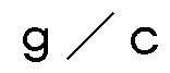
- the non-woven structure has any of the above-mentioned shapes, its apparent density is preferably ⁇ . More preferably ⁇ . Above all, more preferably 0.20 It is 3 or more, also preferably ⁇ . 6 0 9 /
- 0 9 / ⁇ 111 is 3 or less.
- the non-woven structure having such an apparent density can be manufactured by, for example, the method described below.
- the apparent density of the nonwoven structure can be measured by the following method. Specifically, the non-woven structure is cut using a single-edged blade (Product No. 3-10) manufactured by Feather Safety Razor Co., Ltd. to form a cross section of the non-woven structure. Next, the scanning electron microscope (model number Use 100) to magnify and observe the cut section. The section of the magnified observation is used as image data or printed matter to measure the thickness of the non-woven structure without load. Fluffy fibers that are unavoidably present on the surface of the non-woven structure are excluded from measurement. The thickness of the non-woven structure is the average value of the thickness in the image enlarged and observed by the above method. After that, the non-woven structure is cut into a predetermined area (for example, 4001X4001), the basis weight is calculated from the mass and area, and the basis weight is divided by the thickness to obtain the apparent density. calculate.
- a predetermined area for example, 4001X4001
- the basis weight is calculated from the mass and area
- the basis weight
- the non-woven structure containing the single fibers has open pores in which fine voids communicate with each other while the constituent fibers have a small diameter. Since they are formed in large numbers and have a low apparent density, the fine particles present on the surface to be cleaned are scraped off with single fibers to efficiently collect and remove the fine particles adhering to the surface to be cleaned. be able to. Further, the fine particles can be retained in the spaces between the fibers to prevent recontamination of the surface to be cleaned. As a result, the cleaning performance of fine particles on the surface to be cleaned is excellent.
- the cleaning member of the present invention when used for cleaning an object to be cleaned such as a semiconductor substrate such as a semiconductor wafer such as a silicon wafer, the particle size of polishing abrasive grains or polishing debris remaining on the surface to be cleaned Since the fine particles having a particle diameter of 100 000 or less can be effectively removed, the frequency of occurrence of surface defects due to the residual fine particles can be reduced.
- the cleaning member when used together with a cleaning liquid such as a polishing liquid, the fine particles generated by polishing can be adsorbed to the cleaning member side together with the cleaning liquid, which makes the cleaning and removal of the fine particles even more excellent.
- the non-woven structure constituting the cleaning member has a porosity within a specific range.
- the porosity (%) is the value calculated from the following equation (1).
- Porosity ( ⁇ / ⁇ ) 100 X ((Single fiber raw material density -(Apparent density of non-woven structure ) / (Density of monofilament raw material
- the porosity of the nonwoven structure in the present invention is preferably 30% or more, more preferably 40% or more, further preferably 50% or more, and preferably 75% or less, It is more preferably 70% or less, still more preferably 65% or less.
- the cleaning member of the present invention is entangled in a non-woven state in which a plurality of monofilament knives 2 are arranged in a random orientation as shown in Fig. 1 (3),
- the distance between fibers varies from short to long, and with this, the size of the voids formed between fibers also becomes random.
- the void distribution of the cleaning member of the present invention is measured as a pore volume distribution, a high peak is observed in a small pore size range.
- the nonwoven structure preferably has a top peak in the range of pore diameters of 50 or less in the pore volume distribution. , And does not have a top peak in the range of pore diameters exceeding 50.
- “having no top peak in the range of pore size exceeding 50” means that the peak height of the highest peak in the range of pore size of 50 or less, that is, based on the top peak, It means that there are no peaks with a peak height greater than half the peak height in the pore size range above 50.
- the sheet is configured as shown in FIG. Textile 1 exists with a certain orientation ⁇ 02020/175496 7 ⁇ (: 170? 2020 /007541
- the void distribution of the non-woven structure is, for example, "I 3 1
- a measurement sample of 0. 029 to 0. 19 is cut out from the measurement target, and the measurement cell containing the measurement sample is set in a mercury porosimeter (Saito Topore V9500, manufactured by Micromeritics). Then, measure the cumulative pore volume V 1 (1_/ 9 ) of the measurement sample when the mercury injection pressure is increased within the specified range. Then, the converted pore size converted according to the following formula (2) On the horizontal axis, I 0 9 differential pore volume ((VI) (I ⁇ 910 ⁇ )
- the pore volume distribution is obtained with the reduced pore diameter ⁇ on the horizontal axis and the cumulative pore volume V 1 differentiated by the logarithmic value of the pore diameter 0 on the vertical axis.
- the range is as follows. Based on the distribution curve of the converted pore size ports obtained under these measurement conditions, the cumulative total value of the converted pore size ⁇ over the range 0.001 to 100 is calculated as the cumulative pore volume V 1 (m L/g). Then, the median value of the pore diameters in the distribution curve is defined as the pore diameter port 0 () in the present invention.
- the nonwoven structure of the present invention has a pore diameter of 50 or less in the above-mentioned pore volume distribution obtained by differentiating the cumulative pore volume by the logarithm of the pore diameter. ⁇ 0 2020/1754 96 8 ⁇ (: 170? 2020 /007541
- the distribution has a top peak in the above range and does not have a top peak in the range of the pore size of more than 50.
- the pore diameter of the non-woven structure is, as the pore diameter, preferably not less than 10 nm, more preferably not less than 500!
- the cumulative pore volume V 1 of the non-woven structure is preferably ⁇ . 8_Rei! _ / 9 or more, is 1. 0_Rei! _ / 9 or more More preferably, it is also preferable that it is 200 1 1_ / 9 or less, The following is more preferable.
- the non-woven structure having the above-mentioned void distribution, pore size and pore volume can be produced, for example, by the method described below.
- the cleaning member of the present invention can change the shape of the non-woven structure contained therein, or combine the non-woven structure with other members, depending on the structure and application of the object to be cleaned. Can be combined.
- the cleaning member 1 can be configured to include a non-woven structure 2 formed of a compact obtained by compression-molding a deposit in which single fibers are entangled.
- the cleaning member 1 shown in the figure is a bulk compression molded product, and has two main surfaces 2 facing each other.
- the non-woven structure 2 in the form of a plate having 2 3 can be used for cleaning an object to be cleaned as it is or by impregnating the non-woven structure with water, a cleaning liquid or the like. That is, in the form shown in the figure, the shape of the cleaning member 1 is substantially the same as the shape of the nonwoven structure 2.
- the effect of the present invention is exhibited even if the cleaning surface of the cleaning member 1 (the surface facing the surface to be cleaned) is any surface, but the efficiency of cleaning is improved. from the viewpoint, the cleaning surface, surface contact area increases with the cleaned surface, i.e. it is preferable that the a face 2 3.
- the cleaning member further includes a support member such as a sponge, a cleaning pad, or a mouth, and is arranged so that the support member and the non-woven structure contact each other. It can also have a different form. ⁇ 0 2020/175496 9 ⁇ (: 170? 2020 /007541
- the sheet-shaped nonwoven structure 2 may be arranged so as to cover the entire surface of the plate-shaped supporting member 3.
- a sheet-like or plate-like bulky nonwoven structure 2 is laminated on at least one plate surface of a plate-like supporting member 3. It can be in the form of a body.
- a support member 3 can be arranged on the upper surface of a sheet-shaped non-woven structure 2 that has been unrolled, that is, a sheet-shaped non-woven structure that is conveyed in one direction by the mouth-to-roll method. It is also possible to adopt a form in which the above is arranged on one surface of the support member 3. Alternatively, as shown in FIG. 3 ([1]), it is also possible to adopt a configuration in which a sheath-shaped non-woven structure 2 is arranged on the peripheral surface of a mouth-shaped support member 3. In the forms shown in FIGS. 3 (a) to ( ⁇ 0), the surface on which the non-woven structure 2 is arranged is used as the cleaning surface in the cleaning member 1 to remove fine particles existing on the surface to be cleaned. It has excellent performance.
- the support member 3 preferably contains polyurethane, polyvinyl acetal, elastomer resin, or the like.
- the basis weight of the nonwoven structure is appropriately selected according to the specific application of the nonwoven structure.
- the permeation time of water droplets is within a specific range.
- the permeation time of water droplets into the sheet-like nonwoven structure is preferably 1 minute or less, more preferably 40 seconds or less, and further preferably 20 seconds or less.
- the retention of the cleaning liquid can be enhanced, and as a result, the removal efficiency of fine particles is further enhanced.
- the hydrophilicity of fibers means that the retention of water or aqueous liquid between the fibers becomes high.
- the permeation time of water droplets into the sheet-like nonwoven structure can be measured, for example, by the following method. In other words, using two pairs of 3_3 plates with a pre_thickness of 1 0 111 111, sandwich both ends of a sheet-shaped non-woven structure, and in that state, tension is applied to the non-woven structure. Was applied to fix the non-woven structure and the laboratory table so as to be separated from each other. Next, ion-exchanged water is made into water droplets 15 and dropped from above the non-woven structure fixed under tension. Visually observe the surface on which the water droplets have been dropped, and the time from the time when the water droplets are dropped until the water droplets are completely invisible is taken as the water droplet penetration time. The size of the non-woven structure to be measured is 80 5 001 1 111, Then, apply tension so that the sample does not slacken and pinch it, and place the sample at the center at a height of 1 Dropped from above.
- the monofilament constituting the non-woven structure is not particularly limited in its production method as long as the thickness is within the above range, and a fiber produced by a melt blown method or an electrospinning method can be used.
- the single fiber used in the present invention is preferably an electrospun fiber.
- Electrospinning refers to discharging a solution or melt containing a resin, which is a raw material of fibers, into an electric field while a high voltage is applied, whereby the discharged solution or melt is elongated and elongated, and the fiber length is increased. It is a method that can form long fibers having a small fiber diameter.
- thermoplastic resin having a fiber-forming property.
- thermoplastic resin examples include polyethylene, ⁇ 0 2020/1754 96 1 1 ⁇ (: 170? 2020 /007541
- the content of the thermoplastic resin used as the raw material resin is the total constituent components of the single fiber.
- 100 parts by mass it is preferably 70 parts by mass or more, more preferably 75 parts by mass or more, further preferably 80 parts by mass or more, and 98 parts by mass. It is preferably not more than 97 parts by mass, more preferably not more than 90 parts by mass, still more preferably not more than 90 parts by mass.
- the dispersion solvent for dispersing the resin is, for example, dimethylsulfoxide, dimethylacetamide, dimethylformamide or 1 ⁇ 1_methylpyrrolidone.
- Polar solvents alcohols such as glycerin, ethylene glycol and ethanol, ketones such as acetone and methyl ethyl ketone, halogenated solvents such as dichloromethane and chloroform, inorganic salt solvents such as nitric acid, zinc chloride aqueous solution, sodium thiocyanate aqueous solution
- solvents such as nitric acid, zinc chloride aqueous solution, sodium thiocyanate aqueous solution
- the single fiber constituting the non-woven structure preferably contains an ionic surfactant.
- an ionic surfactant By adding an ionic surfactant to the single fiber, it is possible to easily manufacture a non-woven structure containing a fine fiber and having a predetermined density.
- the single fiber is formed by electrospinning. In this case, the charge amount of the raw material resin can be increased, so that the solution or melt containing the resin can be efficiently drawn, and as a result, fibers with a smaller diameter can be produced with high production efficiency. .. Furthermore, hydrophilicity can be easily expressed in the produced fiber. ⁇ 0 2020/175496 12 (: 170? 2020 /007541
- the content of the ionic surfactant is preferably 2 parts by mass or more, and more preferably 4 parts by mass or more, relative to 100 parts by mass of all the constituent components of the single fiber. , 5 parts by mass or more, more preferably 10 parts by mass or less, more preferably 8 parts by mass or less, and further preferably 6 parts by mass or less.
- Examples of the ionic surfactant include a cationic surfactant, a zwitterionic surfactant, and an anionic surfactant.
- a cationic surfactant may be used alone.
- these ionic surfactants may be used in combination of two or more kinds as long as they are surfactants having the same ionicity.
- a plurality of cationic surfactants may be used, a plurality of amphoteric surfactants may be used, and a plurality of anionic surfactants may be used.
- Examples of the cationic surfactant include amine salt type cation surfactants such as fatty acid ester amine salt, fatty acid amide amine salt, urea condensed amine salt, and imidazoline salt, tetraalkylammonium salt, and trialkylbenzyl acetate.
- Examples thereof include quaternary ammonium salt type cationic surfactants such as ammonium salts, quaternary ammonium organic acid salts, fatty acid amide type quaternary ammonium salts, and alkylpyridinium salts.
- zwitterionic surfactants include aminoglutamates, alkyl-/3-alanine, or salts thereof, such as amino acid-type zwitterionic surfactants, and betaine-type zwitterionic surfactants such as alkyl betaine. Is mentioned.
- anionic surfactant examples include caprylic acid, capric acid, lauric acid, myristic acid, palmitic acid, stearic acid, oleic acid, linoleic acid, linolenic acid, arachidic acid, behenic acid, and erucic acid.
- Alkylether sulfates ([3 ⁇ 4- ⁇ one (Rei_1 ⁇ 1 2 Rei_1 - 1 2 ⁇ ) "-3_Rei 3 1 ⁇ / 1) alkyl ether sulfates such as, alkyl sulfonates ([3 ⁇ 4-3 ⁇ 3 1 ⁇ /1), alkyl benzene sulfonate ([3 ⁇ 4-11 -3 ⁇ 3 1 ⁇ /1), alkylnaphthalene sulfone (
- Dialkyl sulfosuccinate [3 ⁇ 4 — ⁇ ⁇ ⁇ 10 1 ⁇ 1 2 — ⁇ 1 ⁇ 1 (- 3 ⁇ 31 1 ⁇ /1) — ⁇ ⁇ ⁇ 1 [3 ⁇ 4), ⁇ 3 ⁇ 4-sulfo fatty acid ester ( [3 ⁇ 4- ⁇ 1 ⁇ 1 (— 3 ⁇ 31 1//1) — ⁇ ⁇ ⁇ — ⁇ 1 ⁇ 1 3 ), acyl isethionate ([3 ⁇ 4 — ⁇ ⁇ 101 ⁇ ( ⁇ 1 _ 1 2 ⁇ 1 _ 1 2 ) — 30 3 IV!), acyl taurine salt ([3 ⁇ 4- ⁇ ⁇ 1 ⁇ 11 ⁇ 1-( ⁇ 1 ⁇ 1 2 ) 2 -3 ⁇ 31 1 ⁇ /1), acyl alkyl taurine salt (8 _ hundred _ (one [3 ⁇ 4 ') one (01 to 1 2) 2 _ 3_Rei 3 1 ⁇ / 1), such as 1 ⁇ ⁇
- sulfate ester salt and sulfonate Represents a linear or branched alkyl group, the carbon number of which is preferably 8 or more, more preferably 10 or more, still more preferably 12 or more, preferably 22 or less, more preferably 20 or more. Or less, more preferably 18 or less.
- IV! represents a monovalent cation, preferably a metal ion, more preferably a sodium ion.
- One of these sulfate ester salts and sulfonates may be used alone, or a mixture of two or more thereof may be used.
- the single fiber contains an ionic surfactant
- an anionic surfactant among the ionic surfactants it is preferable to use a sulfonate.
- a fine fiber having a small diameter and a non-woven structure having a predetermined density can be efficiently produced.
- the cleaning member of the present invention may contain a constituent component other than the raw material constituting the single fiber in the non-woven structure as long as the effects of the present invention are exhibited.
- a constituent component other than the raw material constituting the single fiber in the non-woven structure as long as the effects of the present invention are exhibited.
- other constituents include polyurethane, polyvinyl acetate, cellulose, and derivatives thereof.
- the other constituent components may be contained, for example, in a fibrous form constituting the non-woven structure, or in a layered form such as being laminated on one surface of the non-woven structure. ..
- the smaller the content of the other constituent components the more preferable, but preferably 0.5 parts by mass or more, and more preferably 1 part by mass or more based on 100 parts by mass of all the constituent components of the single fiber. And preferably not more than 95 parts by mass, more preferably not more than 90 parts by mass.
- an additive may be added to the single fiber as long as the effect of the present invention is not impaired.
- additives examples include antioxidants, light stabilizers, ultraviolet absorbers, lubricants, antistatic agents and metal deactivators.
- antioxidants examples include phenol-based antioxidants, phosphite-based antioxidants, and thio-based antioxidants.
- Examples of the light stabilizer and the ultraviolet absorber include hindered amines, nickel complex compounds, benzotriazoles, benzophenones and the like.
- Examples of the lubricant include higher fatty acid amides such as stearic acid amide.
- Examples of the antistatic agent include fatty acid partial esters such as glycerin fatty acid monoester.
- Examples of metal deactivators include phosphons and epoxies. ⁇ 0 2020/1754 96 15 ⁇ (: 170? 2020 /007541
- Triazoles Triazoles, hydrazides, oxamids and the like.
- the content of the additive is preferably 0.001 part by mass or more based on 100 parts by mass of all the constituent components of the single fiber, and 0.05 part by mass. It is more preferable that the amount is not less than 10 parts by mass, preferably not more than 10 parts by mass, further preferably not more than 1 part by mass.
- the non-woven structure constituting the cleaning member is preferably impregnated with a cleaning liquid, depending on the purpose of cleaning, from the viewpoint of enhancing the cleaning efficiency of the particles to be cleaned.
- a cleaning liquid water alone or in addition to water, surfactants, bactericides, fragrances, fragrances, deodorants, ! ⁇ 1 regulators, organic solvents such as alcohol and cleaning agents such as abrasive particles can be used.
- the dispersion liquid include:
- the method comprises a spinning step of discharging a solution or melt of an electrospinning composition containing a raw material of monofilaments into an electric field, and spinning by an electrospinning method to form a monofilament deposit; Is roughly divided into two steps: a pressing step of forming a non-woven structure having a predetermined density by pressing.
- the manufacturing apparatus 10 shown in FIG. 4 is roughly divided into a composition supply section 10 ! ⁇ , an electrode section 10 _, a fluid ejection section 10 ⁇ 3, and a collection section 10 port.
- the manufacturing apparatus 10 has a housing 11, a discharge nozzle 12 and a composition supply section 10 including a hopper 19 for supplying the electrospinning composition 1.
- the electrospinning composition 1 supplied from the hopper 19 can be heated and melted in the case 11 to form a melt 8 of the electrospinning composition.
- a screw (not shown) provided in the casing 11 can supply the molten liquid in the direction of a discharge nozzle 12 described later.
- the discharge nozzle 12 is a member that discharges the molten liquid into an electric field, and includes a nozzle base 13 and a discharge nozzle tip portion 14.
- the discharge nozzles 12 are made of a conductive material such as metal.
- the nozzle base 13 and the discharge nozzle tip portion 14 are electrically insulated by an insulating member (not shown).
- the case 11, the discharge nozzle 12 and the nozzle base 13 are in communication with each other, so that the molten liquid 8 in the case 11 can be discharged from the discharge port of the discharge nozzle tip part 14. Has become.
- the discharge nozzle tip 14 is grounded and grounded.
- the tip portion 14 of the discharge nozzle is heated by, for example, heat transfer from a heater (not shown) provided in the nozzle base 13 or heat transfer from the molten liquid in the housing 11. There is.
- the heating temperature of the melt in the discharge nozzle tip 1 depending on the components of the electrospun composition, preferably 1 0 0 ° ⁇ As, more preferably 2 0 0 ° ⁇ As, preferably 4500° or less, more preferably 400° or less
- the manufacturing apparatus 10 has an electrode section 10 having a charging electrode 21 and a high voltage generator 22 connected to the charging electrode 21.
- the charging electrode 21 is arranged at a position separated from the discharge nozzle tip 14 by a predetermined distance, facing the discharge nozzle tip 14 and spaced apart.
- the charging electrode 21 is preferably made of a conductive material such as metal or covered with a dielectric.
- the distance between the discharge nozzle 12 and the charging electrode 21 depends on the fiber diameter (diameter) of the desired fiber and the accumulating property on the collecting electrode 27 described later, but is preferably 10 or more. ⁇ 0 2020/1754 96 17 ⁇ (: 170? 2020 /007541
- the distance between the discharge nozzle 12 and the charging electrode 21 is within this range, sparks and corona discharge are less likely to occur between the discharge nozzle 12 and the charging electrode 21 and the manufacturing equipment 10 malfunctions. Is hard to happen.
- the manufacturing apparatus 10 further includes a fluid ejecting unit 10 ⁇ 3.
- the fluid ejecting unit 100 is provided with a fluid ejecting device 23 below a virtual straight line connecting the composition supplying unit 100 and the electrode unit 10m.
- the fluid ejection device 23 is provided between the composition supply unit 10 and the electrode unit 10.
- An air flow is flowing between the tip of the discharge nozzle tip portion 14 and the charging electrode 21 in a direction intersecting the direction connecting the two. This air flow is ejected from the fluid ejection device 23.
- the molten liquid discharged from the tip portion 14 of the discharge nozzle can be transferred to an air stream to form finer fibers.
- air it is preferable to use air as the heating fluid as the air stream 8.
- the temperature of the heated air depends on the components of the composition for electrospinning, but it is preferably 100°C or higher, more preferably 200°C or higher, and preferably 500°C or higher. It is less than or equal to 0°, more preferably less than or equal to 400°.
- the flow rate of the air flow at the discharge port of the fluid ejecting device 23 when ejecting the air flow is preferably 5 0 1 _ / 0 1 ⁇ or more, and more preferably. n or more, and preferably n or less, more preferably It is less than or equal to n.
- the manufacturing apparatus 10 further includes a collection unit 10 port.
- the collecting section 10 is equipped with a collecting sheet 24 for collecting fibers, a carrying conveyor 25 for carrying fibers, a high voltage generator 26 and a collecting electrode 27.
- the collection part 100 is provided at a position above a virtual straight line connecting the composition supply part 10 and the electrode part 10 and at a position facing the fluid ejection part 1 0 ⁇ 3. ing. Each of the collection units 100 is electrically connected. ⁇ 0 2020/1754 96 18 ⁇ (: 170? 2020 /007541
- collecting sheet 2 4 is transported in the transport conveyor 2 5 drawn out from the raw mouth Lumpur 2 4 3.
- a collection electrode 27 for collecting the electrospun fibers is arranged inside the transport conveyor 25, a collection electrode 27 for collecting the electrospun fibers is arranged.
- a high voltage generator 26 is connected to the collector electrode 27, and a high voltage is applied to the collector electrode 27 by the high voltage generator 26.
- the fibers are attracted to the negatively charged transport conveyor 25 side and deposited on the surface of the collection sheet 24. Further, the collection electrode 27 may be grounded instead of the high voltage generator 26.
- the hopper 19 is filled with the electrospinning composition 1, and the electrospinning composition is heated and melted in the housing 11.
- the melt is extruded toward the discharge nozzle 12, and the melt is supplied to the discharge port of the discharge nozzle tip portion 14.
- the electrospinning composition 1 contains a thermoplastic resin, which is a raw material resin of a target single fiber, and, if necessary, an ionic surfactant and an additive, and a mixture thereof. Can be used.
- the method for producing the electrospinning composition 1 is not particularly limited, and may be produced, for example, as a masterbatch by previously mixing the respective raw materials. Alternatively, each raw material may be individually supplied to the production apparatus 10. It may be produced by kneading while feeding and heating and melting in the apparatus.
- the molten liquid is discharged from the discharge nozzle tip portion 14 into an electric field and is spun by the electrospinning method (spinning step).
- This electric field can be generated by, for example, grounding the tip portion 14 of the discharge nozzle 12 and connecting the charging electrode 21 to the high voltage generating device 22 to apply a voltage. ..
- the electrically charged melt is made into ultrafine fibers by repeating stretching due to the attractive force and the self-repulsive force due to the charge of the melt itself, and becomes an electrically attractive force toward the charging electrode 21. ⁇ 0 2020/175496 19 ⁇ (: 170? 2020 /007541
- the discharge amount of the melted electrospinning composition is 1 It is preferable that it is more than ⁇ , 29 It is more preferable that it is not less than ⁇ , and it is more preferable that it is not more than 209 / ⁇ !
- the melt flow rate (1 ⁇ /1 [3 ⁇ 4) of the melted electrospinning composition is set from the viewpoint of facilitating stretching of the melt during electrospinning and making the fiber to be produced thinner.
- Melt flow rate (IV! [3 ⁇ 4) is in accordance with "I 3 ⁇ 7 210.
- polypropylene resin is used as the raw material resin, under the load of 230 ° ⁇ , 2.1 6 1 ⁇ 9 , Hole diameter 2.0 9 5 111 111, measured with a die with length 80!
- the molten liquid discharged from the discharge nozzle tip portion 14 is further stretched and fine fibers are generated. While being transported.
- the molten liquid discharged from the tip of the discharge nozzle ⁇ 14 is conveyed to the air stream 8 before reaching the charging electrode 21 and its flight direction changes and the molten liquid is stretched.
- Fibers are produced by being extremely thinned and solidified.
- the fibers generated from the molten liquid are conveyed by the air stream 8 and are attracted by the electric attraction generated in the collecting electrode 27, and are deposited on the surface of the collecting sheet 24 facing the fluid ejecting device 23. To do.
- the applied voltage applied between the discharge nozzle 12 and the charging electrode 21 or the collecting electrode 27 is preferably 1 1 ⁇ 0 1 ⁇ V or more, more preferably 1 8 0 1 ⁇ V or more. Further, it is preferably 1 5 1 ⁇ or less, more preferably 1 10 1 ⁇ V or less. When the applied voltage is within this range, the melt is easily charged with good charge, and the production efficiency of fibers having a small fiber diameter can be further enhanced.
- Spark and corona discharge are less likely to occur between the charging electrode 21 and the collecting electrode 27, and malfunction of the device is less likely to occur.
- the fiber thus produced is considered to be one continuous fiber, that is, a single fiber, between the discharge nozzle 12 and the collection sheet 24. Even if the fibers are temporarily cut due to the manufacturing conditions and the surrounding environment, the cut fibers will immediately come into contact with each other, and as a result, the ultrafine fibers will be collected from the discharge nozzle 1 2 to the collection sheet. By the time of 24, it is considered as if it were one continuous fiber.
- the monofilaments are deposited on the collection sheet 24 to form a monofilament stack on the collection sheet 24.
- the single fiber and the deposit thereof produced through the above steps are spun using the above-described electrospinning composition as a raw material, and there is substantially no alteration of the composition by melt electrospinning. Therefore, the composition of the electrospinning composition as the raw material and the composition of the monofilament as the product are substantially the same.
- a discharge nozzle that discharges a solution of an electrospinning composition a syringe that communicates with the discharge nozzle and can supply the electrospinning composition to the discharge nozzle, and a spun fiber are collected.
- a conductive collector (not shown) is provided for spinning, and spinning can be performed with a voltage applied between the syringe and the conductive collector.
- the syringe contains a solution of the composition, the solution is supplied from a syringe to a discharge nozzle, the solution is discharged from the discharge nozzle into an electric field, and an ultrafine single particle containing a raw material resin is prepared by electrospinning.
- the fibers can be spun to form a monofilament stack on the conductive collector.
- nanofibers having extremely small fiber diameters. ⁇ 0 2020/1754 96 21 ⁇ (: 170? 2020 /007541
- the median fiber diameter of the single fiber is, as described above, preferably 1 O O n m or more and 2 0 0 0 1 ⁇ O! or less.
- the average fiber length of the single fibers is preferably 10 or more, more preferably 50 or more, and further preferably 100 or more!
- the average fiber length of a single fiber can be taken as the arithmetic average value by measuring the length of 500 fibers in the longitudinal direction.
- the apparent density is preferably 0 by pressing the formed monofilament stack.
- the pressure and temperature applied should be controlled and pressed. Further, the applied pressure can be appropriately changed so that the nonwoven structure has a desired shape.
- the obtained monofilament stack is used to measure the dimensions of the target non-woven structure and A compression-molded nonwoven structure 2 can be obtained by putting the mold in a mold corresponding to the shape and applying pressure.
- the pressure applied to the deposit is preferably 10 As described above, more preferably 1 0 0 1 ⁇ 1 / ⁇ 12 or more, and preferably
- the temperature at the time of pressing can be appropriately set at a temperature that does not exceed the melting point or pour point of the raw material resin of the single fiber.
- the temperature is set based on the resin having the lowest melting point or pour point among the resins used.
- the pour point is the length of resin to be measured 4 01 01 01 Width 5 01 01 X thickness It is made into a rate-like solid, and this is applied to a viscoelasticity measuring device (for example, 011 ⁇ /1718700 manufactured by Hitachi High-Tech Science Co., Ltd.). Dynamic viscoelasticity is measured while raising the temperature to the glass transition point of the resin to be measured and the temperature range higher than the glass transition region (frequency at measurement is 1 1 to 1 2, strain amplitude is 0.025% When the storage elastic modulus' is higher than the loss elastic modulus ", the loss elastic modulus ⁇ 0 2020/1754 96 22 ⁇ (: 170? 2020 /007541
- the pressure and temperature at the time of pressing can be set to the above-mentioned pressure and temperature.
- the cross-sectional shape of at least one monofilament at the contact point between the monofilaments without fusion is transformed into a shape different from the cross-sectional shape of the monofilament at the non-contact point.
- washing member 1 including the non-woven structure 2 and the support member 3 can be obtained by further performing a step of winding the body 2 around the outer surface of the support member.
- the method for joining the non-woven structure 2 and the support member 3 is not particularly limited as long as the effects of the present invention are exhibited, and for example, by using a joining means such as heat sealing or an adhesive, it can be partially or entirely used. Can be joined together.
- the composition for electrospinning contains an ionic surfactant, from the viewpoint of more effectively expressing hydrophilicity on the fiber surface and enhancing hydrophilicity of the nonwoven structure, at least the nonwoven structure is used. It is also preferable to subject the body to heat treatment.
- the heat treatment method is not particularly limited as long as the fusion of the single fibers does not occur.
- a method in which hot air is blown onto the fibers for treatment, a method for irradiating the fibers with infrared rays, or heating for hot water is used.
- Method of immersing fiber in liquid, method of passing fiber between a pair of heated mouths, holding fiber in a heated space such as a constant temperature bath ⁇ 0 2020/1754 96 23 ⁇ (: 170? 2020 /007541
- heat treatment may be performed at a temperature not exceeding the melting point or pour point of the raw material resin of the single fibers.
- the cleaning member including the non-woven structure manufactured in this manner can be used as a cleaning member alone, or by being attached to a cleaning tool such as a wiper or a cleaning device, a building such as a floor or a wall surface, a cabinet, It can be used for cleaning windows, mirrors, doors, doorknobs and other fittings, rugs, furniture, tabletop furniture, and the surface of objects to be cleaned such as the skin surface of the body.
- a cleaning tool such as a wiper or a cleaning device
- a building such as a floor or a wall surface, a cabinet
- It can be used for cleaning windows, mirrors, doors, doorknobs and other fittings, rugs, furniture, tabletop furniture, and the surface of objects to be cleaned such as the skin surface of the body.
- the cleaning member may be used in a dry state or may be used in a state in which a cleaning liquid or a chemical liquid is impregnated.
- the cleaning member of the present invention can effectively clean and remove fine particles having a particle size of several tens to several hundreds n°!, such as polishing abrasive particles, a semiconductor substrate such as a silicon wafer or a It can be suitably used for cleaning the surfaces of precision electronic components such as magnetic recording substrates for which the smoothness of the surface to be cleaned is highly required, and the frequency of surface defects on these substrates can be reduced.
- the present invention has been described above based on its preferred embodiments, the present invention is not limited to the above embodiments.
- the composition supply unit 10 and the fluid ejection unit 100 were separately provided, but instead of this, the composition supply unit 10 and the fluid ejection unit 1 0 ⁇ 3 may be included.
- an electric field is generated between a nozzle for discharging a solution or a melt of an electrospinning composition and the nozzle.
- An electrode, a high-voltage generator that applies a voltage to the electrode, and a collection unit that collects fibers generated from the electrospinning composition, and a solution or a melt is circulated between the casing and the nozzle.
- a manufacturing apparatus in which a possible flow passage is formed and a fluid injection unit is formed so as to surround the flow passage may be used. ⁇ 0 2020/1754 96 24 ⁇ (: 170? 2020 /007541
- a voltage is applied to the collection electrode 27 at the port of the collection unit 10 instead of the electrode unit 10 to generate an electric field between the collection electrode 27 and the nozzle, and in this state, from the discharge nozzle 12
- the solution or the molten liquid may be directly ejected toward the mouth of the collection unit 10.
- the fluid ejecting section 10 ⁇ 3 in this embodiment is capable of ejecting the air stream 8 along the ejection direction of the molten liquid in the ejection nozzle 12.
- the electrode for generating an electric field between the discharge nozzle 12 and the discharge nozzle 12 was provided as the charging electrode 21 separately from the composition supply section 108.
- the charging electrode 21 may be incorporated in the composition supply section 108.
- the charging electrode 21 is a concave curved electrode in which a concave curved surface is arranged so as to surround the discharge nozzle 12.
- a voltage may be applied to the electrode.
- the collecting section 100 arranged facing the discharge nozzle 12 is provided with a suction means such as a suction box which is not electrically connected, instead of the collecting electrode 27.
- a suction means such as a suction box which is not electrically connected, instead of the collecting electrode 27.
- the spun fibers may be sucked and the fibers may be deposited on the collection sheet 24.
- the present invention further discloses the following cleaning member and a method for manufacturing the same.
- a non-woven structure that is retained by the entanglement of single fibers having a median fiber diameter of 100 0 or more and 200 0 0 n or less,
- the nonwoven structure has an apparent density of 0.0 5 9 / Rei_rei_1 3 or more ⁇ . 6 is 0 9 / hundred! 3 below, the cleaning member.
- the non-woven structure has a porosity of not less than 30% and not more than 75%, and in the pore volume distribution obtained by differentiating the cumulative pore volume by the logarithmic value of the pore diameter, in the pore diameter range of 50 or less. It has a top peak and a pore size range of more than 50. ⁇ 0 2020/175496 25 ⁇ (: 170? 2020 /007541
- the cleaning member according to ⁇ 1> which has a distribution that does not have a top peak in the surrounding area.
- the cleaning member according to ⁇ 4> wherein the non-woven structure is arranged so as to cover the entire surface of the support member.
- the cleaning member according to ⁇ 4> wherein the sheet-shaped or bulk-shaped non-woven structure is arranged on at least one surface of the plate-shaped support member.
- the cleaning member according to ⁇ 4> wherein the sheet-shaped non-woven structure is arranged on the peripheral surface of the mouth-shaped support member.
- the non-woven structure is in the form of a sheet, and the penetration time of water droplets into the non-woven structure is preferably 1 minute or less, more preferably 40 seconds or less, and further preferably 20 seconds or less.
- the cleaning member according to any one of ⁇ 1> to ⁇ 8>.
- the single fiber contains a thermoplastic resin
- the thermoplastic resin may be polyethylene, polypropylene, polyolefin resin such as ethylene-refin copolymer, ethylene-propylene copolymer, polyester resin such as polyethylene terephthalate, polyamide resin such as polyamide 6 and polyamide 66, polyamine resin. At least one selected from vinyl-based resins such as vinyl chloride and polystyrene, and acrylic-based resins such as polyacrylic acid and polymethylmethacrylate, and the like described in any one of the above items ⁇ 1> to ⁇ 10>. Cleaning member.
- the content of the thermoplastic resin is preferably 70 parts by mass or more, and more preferably 75 parts by mass or more, based on 100 parts by mass of all the constituent components of the single fiber. It is more preferably 0 parts by mass or more, preferably 98 parts by mass or less, and more preferably 97 parts by mass or less,
- the cleaning material according to ⁇ 11> further preferably 90 parts by mass or less.
- the content of the ionic surfactant is preferably 2 parts by mass or more, more preferably 4 parts by mass or more, and 5 parts by mass with respect to 100 parts by mass of all the constituent components of the single fiber. It is more preferably not less than 10 parts by mass, more preferably not more than 10 parts by mass, more preferably not more than 8 parts by mass, further preferably not more than 6 parts by mass, in the above ⁇ 13> The cleaning member described.
- the apparent density of the nonwoven structure is preferably ⁇ . 05 9 / ⁇ 3 or more, more preferably ⁇ . More preferably ⁇ .
- the non-woven structure has a porosity of preferably 30% or more, more preferably 40% or more, further preferably 50% or more, and preferably 75% or less, more preferably 70% or less, and further preferably The cleaning member according to any one of ⁇ 1> to ⁇ 15>, which is 65% or less.
- the cumulative pore volume of the non-woven structure is preferably more than 0.80! !_/9, more preferably more than ! 0 !_/9, and 20 ⁇ 11_. /9 or less, preferably 10
- Electrospinning is performed using the electrospinning composition containing a resin to form a monofilament deposit containing the resin,
- the apparent density is ⁇ when the deposit is pressed. 6 0 9 /
- the obtained monofilament stack was supplied to a hand press machine (IV! ⁇ n ⁇ 6 3 "6 3 3-10 manufactured by Toyo Seiki Co., Ltd.) to obtain room temperature (25 ° ⁇ ).
- a sheet-shaped non-woven structure which was shaped by the entanglement of monofilaments, was manufactured by pressing it with 9 4 0 0 1 ⁇ 1 / ⁇ 0 1 2.
- the thickness of this non-woven structure was 7 6.
- the penetration time of water droplets was 45 seconds
- the apparent density of the non-woven structure was 0.4. 3 and the porosity is 5 5% had a pore distribution showing the top peaks at pore diameters of 8.
- This non-woven structure is arranged so as to cover the entire outer surface of a plate-shaped supporting member (a substrate cleaning pad made of polyvinyl acetate, manufactured by Aion Co., Ltd., model number: series), and A cleaning member 1 was obtained.
- the plate-shaped support member described above was used as it was as a cleaning member.
- the cleaning member of this comparative example consisted only of the plate-shaped support member and did not have the non-woven structure. ⁇ 0 2020/1754 96 30 ⁇ (: 170? 2020 /007541
- a cleaning member composed of a non-woven structure which is a compression molded body was manufactured. Specifically, the monofilament stack obtained by the method described above (basis weight: 1 9 9 / 0! 2 ) was X Horizontal 1 8 0 1 0 1 Depth 3 0 01 01 Insert into a rectangular parallelepiped mold, then,
- Example 1 and Comparative Example 1 The cleaning member of Example 1 and Comparative Example 1 was mounted on a substrate cleaning apparatus, and the number of surface defects on the silicon wafer was measured to evaluate the particle cleaning performance.
- the specific procedure was as follows: finish polishing of the silicon wafer, cleaning with a cleaning member, and measurement of surface defects. Details of the evaluation procedure and conditions are shown below.
- the final polishing of the silicon wafer was performed under the following polishing conditions.
- Rough polishing was performed on a silicon wafer using a commercially available polishing liquid, and then finish polishing was performed under the following final polishing conditions.
- the haze of a silicon wafer after rough polishing is 2 to 3 Met.
- the haze is a value in the dark field wide oblique incidence channel (mouth) measured using a 1_8-chome ⁇ ⁇ “Made in 3” “3 3 0 3 3 39 1 device.
- Hydroxyethyl cellulose manufactured by Daicel Co., Ltd., 3 1400, molecular weight 250,000
- polyethylene glycol (6) 600 weight average molecular weight 600, Wako Pure Chemical Industries Ltd.
- Wako first grade ammonia water
- silica particles ? !_ _ 3, Fuso Kagaku Kogyo Co., Ltd.
- polishing obtained by mixing ion-exchanged water.
- the liquid concentrate was diluted 40 times with ion-exchanged water to obtain a final polishing liquid.
- finishing polish ⁇ 02020/175496 31 ⁇ (: 170? 2020 /007541
- composition is as follows.
- Hydroxyethyl cellulose 0.01 mass%
- Single-crystal silicon wafer 200 mm diameter silicon single-sided mirror-polished wafer, conductivity type: P, crystal orientation: 100, resistivity: 0.1 Q cm or more and 100 Q cm unsatisfactory
- Polishing machine Single-sided 8-inch polishing machine “GR I N D— X SP P 600 s” (Okamoto Manufacturing)
- -Polishing pad Suede pad (Toray Cortex, Asker hardness: 64, Thickness: 1.37 mm, Nap length: 450 m, Opening diameter: 60 /xm)
- the silicon wafer was subjected to a total of 2 sets, with one set including cleaning with a cleaning member, ozone cleaning, and diluted hydrofluoric acid cleaning. After that, the cleaned silicon wafer was spun at 1,500 rpm for 2 minutes for spin drying. The conditions of each washing were as follows.
- the cleaning time was 1 minute.
- ozone water at room temperature (23 °C) containing 20 ozone was directed toward the center of a silicon wafer rotating at 600 "01 at a flow rate of 1 !_ / n for 3 minutes. Jetted.
- the surface defects of the silicon wafer after cleaning are present on the surface of the silicon wafer by using the ⁇ !_8 Tencor "3 Li 3 0 3 1 ⁇ 3 1 — 0 1_ 3" device.
- the evaluation was performed by measuring the number of particles having a particle size of n or more and 50 n or less.
- the evaluation results of the surface defects were evaluated based on the value at the dark-field oblique beam composite channel (0(30) measured by the above-mentioned apparatus. The smaller this value is, the smaller the surface defects are.
- FIGS. 5(3) and (3) The numbers of surface defects generated on the silicon wafers when the cleaning members of Example 1 and Comparative Example 1 were used for cleaning are shown in FIGS. 5(3) and (3) as the results.
- Figure 5 (a) shows that the smaller the number of white spots in the inner black area surrounded by the circle, the less the occurrence of surface defects, and the better the cleaning performance for fine particles.
- the cleaning member of Example 1 has less fine particles remaining on the surface of the silicon wafer as compared with the cleaning member of Comparative Example 1. It can be seen that the number of defects is small. Therefore, the cleaning material of the present invention has excellent fine particle cleaning performance, and is particularly suitable for cleaning precision electronic components such as substrates for which effective removal of fine particles is desired.
- a cleaning member having excellent cleaning performance for fine particles adhering to the surface to be cleaned.
Landscapes
- Engineering & Computer Science (AREA)
- Textile Engineering (AREA)
- Mechanical Engineering (AREA)
- Nonwoven Fabrics (AREA)
- Cleaning Implements For Floors, Carpets, Furniture, Walls, And The Like (AREA)
- Spinning Methods And Devices For Manufacturing Artificial Fibers (AREA)
- Cleaning In General (AREA)
Abstract
本発明の洗浄用部材(1)は、メジアン繊維径が100nm以上2000nm以下である単繊維の絡合によって保形されている不織構造体(2)を備える。不織構造体(2)は、見かけ密度が0.05g/cm3以上0.60g/cm3以下である。洗浄用部材(1)は、支持部材(3)を更に備え、支持部材(3)と不織構造体(2)とが互いに接するように配されていることも好適である。単繊維が電界紡糸された繊維であることも好適である。また、本発明の洗浄用部材の製造方法は、電界紡糸法によって紡糸して単繊維の堆積体を形成する工程と、該堆積体を押圧して、見かけ密度が0.05g/cm3以上0.60g/cm3以下の不織構造体を形成する工程とを備える。
Description
\¥0 2020/175496 1 卩(:17 2020 /007541
明 細 書
発明の名称 : 洗浄用部材及びその製造方法
技術分野
[0001 ] 本発明は、 洗浄用部材及びその製造方法に関する。
背景技術
[0002] 近年、 直径が数 以下である極細繊維が、 その繊維を交絡させた繊維集 合体の形態で様々な用途に用いられている。 例えば、 特許文献 1 には、 数平 均による単繊維の直径が 1〜 4 0 0 n
 全極細繊維における単繊維の直径
 の単繊維の重量比率が 6 0 %以上の極細繊維及び/または 極細繊維束が絡合してなる不織布からなる洗浄加工布が開示されている。 同 文献には、 この洗浄加工布が緻密な構造を有しており、 磁気記録媒体用基板 の洗浄に使用可能であることも開示されている。
先行技術文献
特許文献
[0003] 特許文献 1 :特開 2 0 0 8 _ 5 5 4 1 1号公報
発明の概要
[0004] 本発明は、 洗浄用部材に関する。
—実施形態では、 前記洗浄用部材は、 メジアン繊維径が 1 0 0 n m以上 2 0 0 0 n 01以下である単繊維の絡合によって保形されている不織構造体を備 ス ·る。
—実施形態では、 前記不織構造体は、 見かけ密度が〇.

0 . 6 0 9 /〇〇! 3以下である。
[0005] また本発明は、 前記洗浄用部材の製造方法に関する。
_実施形態では、 前記製造方法は、 電界紡糸用組成物の溶液又は溶融液を 電場中に吐出し、 電界紡糸法によって紡糸して、 単繊維の堆積体を形成する 工程を備える。
_実施形態では、 前記製造方法は、 前記堆積体を押圧して、 密度が 0 . 0
\¥0 2020/175496 2 卩(:17 2020 /007541
 以下の不織構造体を形成する工程を備え る。
図面の簡単な説明
[0006] [図1]図 1 (3) は、 本発明の洗浄用部材が備える不織構造体に含まれる単繊 維の絡合状態を示す模式図であり、 図 1 (匕) は、 従来技術の繊維シート表 面に存在する繊維の配置形態を示す模式図である。
[図 2]図 2は、 本発明の洗浄用部材の一実施形態を示す模式図である。
[図 3]図 3 ( 3 ) ないし ( ¢0 は、 本発明の洗浄用部材の別の実施形態を示す 模式図である。
[図 4]図 4は、 製造装置を用いた単繊維の製造方法を示す模式図である。
[図 5]図 5 ( 3 ) 及び ( ) は、 実施例及び比較例の洗浄用部材を用いて洗浄 したときの微粒子の除去性能を示す画像及びグラフである。
発明の詳細な説明
[0007] ところで、 特許文献 1 に記載の洗浄加工布は、 緻密且つ高密度な構造によ って、 洗浄対象面上に残存する研磨砥粒や研磨屑等の微粒子を搔き出して除 去するものである。
しかし、 同文献に記載の洗浄加工布は、 微粒子の搔き出しによる除去が不 十分であり、 微粒子の洗浄効率の向上が望まれていた。
[0008] したがって、 本発明は、 洗浄対象面に付着した微粒子の洗浄性能を向上す る洗浄用部材及びその製造方法に関する。
[0009] 以下本発明を、 その好ましい実施形態に基づき図面を参照しながら説明す る。 本発明は洗浄用部材に係るものである。
本発明における洗浄とは、 対象物の清掃及び清拭の両方の意味を含むもの であり、 例えば、 床面、 壁面、 天井及び柱等の建物の清掃、 建具や備品の清 掃、 各種物品の拭き取り、 身体及び身体に係る器具の清拭等が含まれる。 本発明の洗浄用部材は、 シリコンウェハや半導体ウェハ等の半導体基板、 磁気記録用基板等といった洗浄対象面の平滑性が要求される精密電子部品の 表面の洗浄に特に好適に用いられる。
\¥0 2020/175496 3 卩(:170? 2020 /007541
[0010] 本発明の洗浄用部材は、 単繊維の集合体からなる不織構造体を備える。 不 織構造体は、 単繊維どうしの絡合によって保形されている。
不織構造体とは、 単繊維がランダムに堆積して、 該単繊維どうしが絡合し た堆積物であり、 必要に応じて、 押圧等の保形が更に施されているものであ る。 単繊維どうしの間には、 単繊維が存在しない空隙がシート面方向及び厚 み方向に貫通して三次元的に存在し、 これとともに該空隙が連通して、 不織 構造体の内部に微細な空孔 (以下、 これを細孔ともいう。 ) を形成している 。 この空孔は、 一般に連通した開空孔となっている。
不織構造体に含まれる単繊維は、 互いに接触する部位を有し得るが、 融着 等によって互いに接着していない。 単繊維どうしが接触する接触点を有する 場合、 単繊維どうしは互いに接着していないが、 単繊維どうしの接触点にお ける少なくとも一方の単繊維の断面形状が、 非接触点における単繊維の断面 形状とは異なる形状に変形していることが好ましい。 本発明における 「単 繊維」 は、 繊維束を形成していない単一の繊維を指し、 繊維束によって形成 された繊維を除外する趣旨である。
[001 1 ] 単繊維のメジアン繊維径は、 好ましくは 1 0 0门 01以上、 より好ましくは
2 0 0 n
 以上、 更に好ましくは 2 5 0 n
 以上であり、 また、 好ましくは 2 0 0 0 n 以下、 より好ましくは 1 0 0 0 n 以下、 更に好ましくは 9 0 0 〇!以下である。
このような繊維径を有する単繊維を用いることによって、 洗浄対象面に付 着した粒径 1 0 0门 01以下の微粒子の除去を効率よく行うことができる。 繊維の繊維径は、 例えば不織構造体の観察対象面を走査型電子顕微鏡 (3 巳 IV!) 観察して、 その二次元画像から繊維の塊、 繊維の交差部分を除いた繊 維を任意に 5 0 0本選び出し、 繊維の長手方向に直交する直線と、 繊維外形 とが交差する 2点の交点間長さを繊維径としたときに、 これらの測定値の中 央値をメジアン繊維径とすることができる。
繊維径が 1 0 0 n 未満、 或いは 2 0 0 0 n 超の繊維が不織構造体に含 まれることは本発明の効果を損なわない限り許容されるが、 望ましくは 1 0
\¥0 2020/175496 4 卩(:170? 2020 /007541
0门 01以上 2 0 0 0 n 01以下の単繊維のみを含む。
[0012] 不織構造体は、 その厚みが好ましくは〇. 0
 以上、 より好ましくは 〇. 0 4 111 111以上、 更に好ましくは〇. 0 6 111 111以上であり、 また、 好まし くは 3 0〇!〇!以下、 より好ましくは 2 5〇!〇!以下、 更に好ましくは
 以下である。
このような厚みを有していることによって、 洗浄用部材の強度を維持しつ つ、 洗浄対象物に付着した微粒子の除去に優れたものとなる。
このような範囲の厚みを有する不織構造体の形状は、 例えば、 シート状で あるか、 或いは板状、 角柱状、 円柱状、 塊状等のバルク状であり得る。
不織構造体の厚みは、 例えば単繊維の含有量や成形時の圧縮等によって適 宜調節することができる。 不織構造体の厚みは、 例えば後述するように、 走 査型電子顕微鏡を用いて、 測定対象の不織構造体の断面を観察することで測 定することができる。
本発明におけるシート状とは、 不織構造体の厚みが 1 0 以上 1 0 0 0 以下のものを指す。
また、 バルク状とは、 肉眼視して外形を認識し得る大きさを有する形状の ことであり、 例えば、 不織構造体における縦、 横及び奥行きの三つの次元の うち、 最も短い次元の長さを厚みとして、 厚みが 1 01 01 01超のものを指す。 ここでいう厚みは、 後述する測定方法によって測定した無荷重での不織構造 体の厚みを意味する。
[0013] 不織構造体が上述したいずれの形状であっても、 その見かけ密度は、 好ま しくは〇.
 より好ましくは〇.
 以上、 更 に好ましくは〇. 2 0
 3以上であり、 また、 好ましくは〇. 6 0 9 /
〇 3以下、 より好ましくは〇.
 以下、 更に好ましくは 0 . 5
0 9 /〇 111 3以下である。
このような密度であることによって、 洗浄対象面に付着した微粒子を単繊 維によってかき取りやすくなるとともに、 単繊維間の空隙を多く して、 除去 対象である微粒子の不織構造体への保持性を高めることができ、 その結果、
\¥0 2020/175496 5 卩(:170? 2020 /007541
洗浄対象物に付着した微粒子の除去を効率的に行うことができる。
このような見かけ密度を有する不織構造体は、 例えば後述する方法によっ て製造することができる。
[0014] 不織構造体の見かけ密度は、 以下の方法で測定することができる。 具体的 には、 フェザー安全剃刀株式会社製の片刃 (品番 3 - 1 0) を使用して 不織構造体を切断し、 不織構造体の断面を形成する。 続いて、 日本電子株式 会社製の走査型電子顕微鏡 (型番
 1 0 0) を使用して、 切り出し た断面を拡大観察する。 拡大観察した断面を画像データや印刷物とし、 無荷 重での不織構造体の厚みを測定する。 不織構造体の表面に不可避的に存在し ている毛羽立った繊維は、 測定対象から除外する。 不織構造体の厚みは、 上 述の方法によって拡大観察した画像における厚みの平均値とする。 その後、 不織構造体を所定の面積 (例えば 4 0 01X4 0 01) となるように切断して、 その質量と面積とから坪量を算出し、 坪量を厚みで除して、 見かけ密度を算 出する。
[0015] 以上の構成を有する洗浄用部材によれば、 単繊維を含む不織構造体は、 構 成繊維が細径のものでありながら、 繊維間に微細な空隙が連通した開空孔と して多数形成されて、 見かけ密度が低いものとなっているので、 洗浄対象面 に存在する微粒子を単繊維によってかき取って、 洗浄対象面に付着している 微粒子を効率的に捕集除去することができる。 また、 該微粒子を繊維間の空 隙に保持して、 洗浄対象面の再汚染を防ぐことができる。 その結果、 洗浄対 象面の微粒子の洗浄性能に優れる。 また、 本発明の洗浄用部材を、 シリコン ウェハをはじめとする半導体ウェハ等の半導体基板等といった洗浄対象物の 洗浄に用いた場合、 洗浄対象面に残存する研磨砥粒や研磨屑等の粒径 1 〇〇 01以下の微粒子を効果的に除去することができるので、 該微粒子の残存に 起因した表面欠陥の発生の頻度を少なくすることができる。
特に、 洗浄用部材を研磨液等の洗浄液とともに用いた場合、 研磨によって 発生した微粒子を洗浄液とともに洗浄用部材側に吸着させることができるの で、 微粒子の洗浄除去に一層優れたものとなる。
\¥0 2020/175496 6 卩(:170? 2020 /007541
[0016] 上述した効果を一層顕著なものとする観点から、 洗浄用部材を構成する不 織構造体は、 その空隙率が特定の範囲であることが好ましい。 空隙率 (%) とは、 以下の式 (1) から算出された値とする。 単繊維の原料を複数含む場 合には、 各原料の密度と、 その含有質量比率から算出された密度を、 単繊維 の原料の密度として用いる。
空隙率 (〇/〇) = 1 0 0 X ( (単繊維の原料の密度
 - (不織 構造体の見かけ密度
 ) / (単繊維の原料の密度

] ) - (1)
[0017] 本発明における不織構造体の空隙率は、 好ましくは 3 0 %以上、 より好ま しくは 4 0 %以上、 更に好ましくは 5 0 %以上であり、 また、 好ましくは 7 5 %以下、 より好ましくは 7 0 %以下、 更に好ましくは 6 5 %以下である。
[0018] 本発明の洗浄用部材は、 図 1 (3) に示すように、 複数の単繊維丁 2がラ ンダムに配向して配置された不織の状態で絡合されているので、 その繊維間 距離は短いものから長いものまで存在し、 これに伴って、 繊維間に形成され た空隙 の大きさもランダムとなる。 その結果、 本発明の洗浄用部材の空隙 分布を細孔容積分布として測定した場合、 小さい細孔径の範囲に高いピーク が観測される。
詳細には、 不織構造体は、 上述した好適な範囲の空隙率を有していること に加えて、 好ましくは、 細孔容積分布において 5 0 以下の細孔径の範囲 にトップピークを有し、 且つ 5 0 超の細孔径の範囲にトップピークを有 していない。 本発明において 「5 0 超の細孔径の範囲にトップピークを 有していない」 とは、 5 0 以下の細孔径の範囲にある最も高いピークの ピーク高さ、 すなわちトップピークを基準として、 該ピーク高さの半分の高 さよりも大きいピーク高さを有するピークが、 5〇 超の細孔径の範囲に 存在していないことをいう。
一方、 従来技術の繊維シート、 すなわち繊維束を用いるか、 又は繊維束が 形成されるように製造した繊維シート、 織布及び編物では、 図 1 (匕) に示 すように、 シートを構成する繊維丁 1が一定の配向性をもって存在している
\¥02020/175496 7 卩(:170? 2020 /007541
。 この場合、 図 1 (匕) に示す従来技術の繊維シートでは、 繊維間距離が相 対的に短く空隙が小さい繊維密集領域 IIと、 繊維間距離が相対的に長く空隙 が大きい繊維離間領域 Vとの二つの領域が存在する。 このような繊維シート の空隙分布を測定した場合、 小さい空隙を有する繊維密集領域由来のピーク と、 大きい空隙を有する繊維離間領域由来のピークとの二つのピークが観測 される。
[0019] 不織構造体の空隙分布は、 細孔容積分布として、 例えば、 」 I 3
 1
1
655に規定される水銀圧入法に準じて、 以下の方法で測定することができ る。
詳細には、 測定対象から〇. 029〜〇. 1 9の測定サンプルを切り出し 、 該測定サンプルを入れた測定セルを水銀ポロシメーター (才一トポア丨 V 9500、 マイクロメリティツクス社製) にセツ トし、 水銀注入圧力 を所 定の範囲内で上昇させていったときの該測定サンプルの累積細孔容積 V 1 ( 1_/9) を測定する。 次いで、 下記の式 (2) に従って換算した換算細孔 径口
 を横軸に、 I 〇 9微分細孔容積 ( (V I)
 ( I 〇 910〇)
; 〇! 1_/9) との関係を縦軸にプロツ トし、 細孔容積分布を得る。 つまり、 換算細孔径〇を横軸にとり、 累積細孔容積 V 1 を細孔径 0の対数値で微分し た細孔容積を縦軸にとって、 細孔容積分布を得る。
□ = 47〇〇 3 @/? - (2)
(7 :水銀の表面張力、 0 :接触角、 :水銀注入圧力)
[0020] 前記測定は 22°〇、 65%[¾ 1~1環境下にて行う。 水銀の表面張力· ^は 48
40 ° 、 水銀注入圧力 は 0 3 I 3 (01\/1
 (4 1 3. 6851\/1 3) 以下の範囲とする 。 この測定条件で得られる換算細孔径口の分布曲線に基づいて、 0. 001 8 以上 1 00 以下の範囲に亙る換算細孔径〇の累積合計値を累積細 孔容積 V 1 (m L/g) とし、 分布曲線における細孔径の中央値を本発明に いう細孔径口0 ( ) とする。 本発明の不織構造体は、 累積細孔容積を細孔 径の対数値で微分した上述の細孔容積分布において、 50 以下の細孔径
\¥0 2020/175496 8 卩(:170? 2020 /007541
(4 1 3. 6851\/1 3) 以下の範囲とする 。 この測定条件で得られる換算細孔径口の分布曲線に基づいて、 0. 001 8 以上 1 00 以下の範囲に亙る換算細孔径〇の累積合計値を累積細 孔容積 V 1 (m L/g) とし、 分布曲線における細孔径の中央値を本発明に いう細孔径口0 ( ) とする。 本発明の不織構造体は、 累積細孔容積を細孔 径の対数値で微分した上述の細孔容積分布において、 50 以下の細孔径
\¥0 2020/175496 8 卩(:170? 2020 /007541
の範囲にトップピークを有し、 且つ 5〇 超の細孔径の範囲にトップピー クを有していない分布を有するものであることが好ましい。
[0021 ] 同様の観点から、 不織構造体の細孔径口。は、 細孔直径として、 1 0 n m以 上であることが好ましく、 5 0 〇!以上であることが更に好ましく、 また、
5〇 以下であることが好ましく、 3 0 以下であることが更に好まし い。
[0022] また同様の観点から、 不織構造体の累積細孔容積 V 1は、 〇. 8〇! !_ / 9 以上であることが好ましく、 1 . 0〇! !_ / 9以上であることが更に好ましく 、 また、 2 0〇1 1_ / 9以下であることが好ましく、
 以下である ことが更に好ましい。 上述した空隙分布、 細孔径及び細孔容積を有する不織 構造体は、 例えば後述する方法によって製造できる。
[0023] 本発明の洗浄用部材は、 洗浄対象物の構造や用途に応じて、 これに含まれ る不織構造体の形状を変更したり、 或いは不織構造体と他の部材とを組み合 わせたりすることができる。
詳細には、 図 2に示すように、 洗浄用部材 1は、 単繊維が絡合した堆積体 を圧縮成形した成形体からなる不織構造体 2を備えた形態とすることができ る。 同図に示す洗浄用部材 1は、 バルク状の圧縮成形体であり、 対向する二 つの主面 2
 2 3を有する板状態である不織構造体 2からなり、 これをそ のままで、 又は不織構造体に水や洗浄液等を含浸させて、 洗浄対象物の洗浄 に供することができる。 つまり、 同図に示す形態では、 洗浄用部材 1の形状 は、 不織構造体 2の形状と実質的に同一である。 同図に示す形態の場合、 洗 浄用部材 1 における洗浄面 (洗浄対象面と対向する面) はいずれの表面であ っても本発明の効果は奏されるが、 洗浄の効率化を図る観点から、 洗浄面は 、 洗浄対象面との接触面積が大きくなる面、 すなわち前記の主面 2 3である ことが好ましい。
[0024] また洗浄用部材は、 不織構造体に加えて、 スポンジ、 洗浄パッ ド又は口一 ル等の支持部材を更に備えて、 支持部材と不織構造体とが互いに接するよう に配された形態とすることもできる。
\¥0 2020/175496 9 卩(:170? 2020 /007541
詳細には、 図 3 ( 3 ) に示すように、 シート状の不織構造体 2が、 板状の 支持部材 3の全面を被覆するように配された形態とすることができる。 ある いは、 図 3 ( b ) に示すように、 シート状の又は板状等のバルク状の不織構 造体 2が、 板状の支持部材 3の少なくとも一つの板面に配された積層体の形 態とすることができる。
[0025] また、 図 3 (〇) に示すように、 シート状の不織構造体 2を繰り出す第 1 口ール 2八と、 繰り出された不織構造体 2を巻き取る第 2口ール 2巳とを備 え、 繰り出されたシート状の不織構造体 2の上面に支持部材 3を配置可能な 形態、 すなわち口ールトゥロール方式で一方向に搬送されているシート状の 不織構造体 2が支持部材 3の一方の面に配された形態とすることもできる。 あるいは、 図 3 ( ¢1 ) に示すように、 口ール状の支持部材 3の周面にシー 卜状の不織構造体 2が配された形態とすることもできる。 図 3 ( a ) ないし ( ¢0 に示す形態では、 不織構造体 2が配された側の面を洗浄用部材 1 にお ける洗浄面として用いることによって、 洗浄対象面に存在する微粒子の除去 性能に優れたものとなる。
特に、 図 3 ( 1〇) ないし (〇1 ) に示す形態では、 支持部材の形状や材質に 依存せず、 既存の支持部材を微粒子の洗浄除去効率が高くなるように、 簡便 に改質して用いることができる点で有利である。 洗浄対象面への意図しない 傷等の欠陥の生成を防ぐ観点から、 支持部材 3は、 ポリウレタン、 ポリビニ ルアセタール、 エラストマー樹脂等を含むものであることが好ましい。
[0026] 不織構造体をシート状に成形する場合には、 不織構造体の坪量は、 不織構 造体の具体的な用途に応じて、 適切な坪量が適宜選択される。
[0027] 次に、 上述の各実施形態に共通して適用可能な事項について説明する。 洗 浄用部材における不織構造体は、 これをシート状としたときに、 水滴の浸透 時間が特定の範囲となっていることが好ましい。 詳細には、 シート状の不織 構造体に対する水滴の浸透時間が 1分以内であることが好ましく、 より好ま しくは 4 0秒以下、 更に好ましくは 2 0秒以下である。
このような水の吸収性を示すことによって、 微粒子の洗浄性能を更に高め
\¥0 2020/175496 10 卩(:170? 2020 /007541
ることができる。 特に、 洗浄用部材を洗浄液とともに用いたときに、 洗浄液 の保持性を高めることができ、 その結果、 微粒子の除去効率が一層高いもの となる。 シート状の不織構造体に対する水滴の浸透時間が短いほど、 単繊維 の親水性が高いことを意味する。
繊維の親水性とは、 繊維間での水又は水性液の保持性が高くなることを指 す。
[0028] シート状の不織構造体に対する水滴の浸透時間は、 例えば以下の方法で測 定することができる。 すなわち、 プレ _卜厚みが 1 0 111 111である _対の 3リ 3プレートを二組用いて、 シート状の不織構造体の両端をそれぞれ挟持し、 その状態で該不織構造体に張力を付与して、 該不織構造体と実験台とが離間 するように固定した。 次いで、 張力を付与した状態で固定した不織構造体の 上方からイオン交換水を水滴として 1 5 し滴下する。 水滴が滴下された面 を目視にて観察し、 水滴の滴下時点から、 水滴が完全に視認できなくなるま での時間を水滴の浸透時間とする。 測定する不織構造体のサイズを 8 0
 5 0〇1 111とし、
 してサンプルが弛 まない程度に張力を付与して挟持し、 中央の位置に高さ 1
 上方から滴 下した。
[0029] 不織構造体を構成する単繊維は、 太さが上述の範囲であればその製造方法 に特に制限はなく、 メルトブローン法や電界紡糸法で製造された繊維を用い ることができる。 特に、 本発明に用いられる単繊維は、 電界紡糸された繊維 であることが好ましい。
このような繊維を用いることによって、 細径繊維を含み且つ所定の密度を 有する不織構造体を簡便に製造することができる。 電界紡糸とは、 高電圧が 印加されている状態で繊維の原料となる樹脂を含む溶液又は溶融液を電界中 へ吐出することによって、 吐出された溶液又は溶融液が細長く引き伸ばされ 、 繊維長が長く、 繊維径が細い繊維を形成することができる方法である。
[0030] 単繊維は、 その原料として、 繊維形成性を有する熱可塑性樹脂を用いるこ とが好ましい。 このような熱可塑性樹脂としては、 例えば、 ポリエチレン、
\¥0 2020/175496 1 1 卩(:170? 2020 /007541
ポリプロピレン、 エチレンー《_オレフィンコポリマー、 エチレンープロピ レンコボリマー等のポリオレフィン樹脂、 ポリエチレンテレフタレート等の ポリエステル樹脂、 ポリアミ ド 6及びポリアミ ド 6 6等のポリアミ ド樹脂、 ポリ塩化ビニルやポリスチレン等のビニル系樹脂、 ポリアクリル酸やポリメ タクリル酸メチル等のアクリル系樹脂などが挙げられ、 これらのうち一種を 単独で又は二種以上を組み合わせて用いることができる。
[0031 ] 原料樹脂として用いられる熱可塑性樹脂の含有量は、 単繊維の全構成成分
1 0 0質量部に対して、 7 0質量部以上であることが好ましく、 7 5質量部 以上であることがより好ましく、 8 0質量部以上であることが更に好ましく 、 また、 9 8質量部以下であることが好ましく、 9 7質量部以下であること がより好ましく、 9 0質量部以下であることが更に好ましい。
[0032] 樹脂の溶液を電界紡糸に供する場合、 樹脂を分散させるための分散溶媒と しては、 例えばジメチルスルホキシド、 ジメチルアセトアミ ド、 ジメチルホ ルムアミ ド及び 1\1 _メチルピロリ ドンなどの非プロトン性極性溶媒や、 グリ セリン、 エチレングリコール及びエタノールなどのアルコール類、 アセトン 及びメチルエチルケトンなどのケトン類、 ジクロロメタン及びクロロホルム などのハロゲン系溶媒、 硝酸、 塩化亜鉛水溶液、 チオシアン酸ナトリウム水 溶液などの無機塩系溶媒が挙げられ、 これらを単独で使用してもよく、 二種 以上の溶媒を混合して使用してもよい。
[0033] また、 不織構造体を構成する単繊維は、 イオン性界面活性剤を含むことが 好ましい。 単繊維にイオン性界面活性剤を含有させることによって、 細径繊 維を含み且つ所定の密度を有する不織構造体を簡便に製造することができる これに加えて、 単繊維を電界紡糸によって形成する場合、 原料樹脂の帯電 量を高めることができるので、 樹脂を含む溶液又は溶融液の延伸を効率よく 行うことができ、 その結果、 より細径の繊維を高い生産効率で製造すること ができる。 更に、 生成した繊維に対して親水性の発現を容易に行うことがで きる。
\¥0 2020/175496 12 卩(:170? 2020 /007541
[0034] イオン性界面活性剤の含有量は、 単繊維の全構成成分 1 0 0質量部に対し て、 2質量部以上であることが好ましく、 4質量部以上であることがより好 ましく、 5質量部以上であることが更に好ましく、 また、 1 0質量部以下で あることが好ましく、 8質量部以下であることがより好ましく、 6質量部以 下であることが更に好ましい。
[0035] イオン性界面活性剤としては、 カチオン性界面活性剤、 両イオン性界面活 性剤及びアニオン性界面活性剤が挙げられる。 これらのイオン性界面活性剤 のうち、 一種を単独で使用してもよい。 また、 これらのイオン性界面活性剤 は、 同一のイオン性を有する界面活性剤であれば、 二種以上を組み合わせて 使用してもよい。 例えば、 イオン性界面活性剤として、 カチオン性界面活性 剤を複数使用してもよく、 両イオン性界面活性剤を複数使用してもよく、 ア ニオン性界面活性剤を複数使用してもよい。
[0036] カチオン性界面活性剤としては、 例えば脂肪酸エステルアミン塩、 脂肪酸 アミ ドアミン塩、 尿素縮合アミン塩、 イミダゾリン塩等のアミン塩型カチオ ン界面活性剤や、 テトラアルキルアンモニウム塩、 トリアルキルベンジルア ンモニウム塩、 第四級アンモニウム有機酸塩、 脂肪酸アミ ド型第四級アンモ ニウム塩、 アルキルピリジニウム塩等の第四級アンモニウム塩型カチオン界 面活性剤等が挙げられる。
両イオン性界面活性剤としては、 例えばアルキルグルタミン酸、 アルキル — /3—アラニン、 又はそれらの塩等のアミノ酸型両イオン性界面活性剤、 ア ルキルべタイン等のベタイン型両イオン性界面活性剤等が挙げられる。
[0037] アニオン性界面活性剤としては、 例えばカプリル酸、 カプリン酸、 ラウリ ン酸、 ミリスチン酸、 パルミチン酸、 ステアリン酸、 オレイン酸、 リノール 酸、 リノレン酸、 アラキジン酸、 ベヘン酸、 エルカ酸等の炭素数 8以上 2 2 以下の飽和又は不飽和の脂肪酸と、 し し N 3、
 巳 3、 门等の金属との塩や、 ポリオキシエチレンアルキルエーテルカルボン酸塩、 アルキルヒドロキシエーテルカルボン酸塩等のカルボン酸塩、 高級アルコー ル硫酸エステル塩 ([¾ _〇_ 3〇3 1\/1) 等のアルキル硫酸塩、 ポリオキシエチ
\¥02020/175496 13 卩(:170? 2020 /007541
巳 3、 门等の金属との塩や、 ポリオキシエチレンアルキルエーテルカルボン酸塩、 アルキルヒドロキシエーテルカルボン酸塩等のカルボン酸塩、 高級アルコー ル硫酸エステル塩 ([¾ _〇_ 3〇3 1\/1) 等のアルキル硫酸塩、 ポリオキシエチ
\¥02020/175496 13 卩(:170? 2020 /007541
レンアルキルエーテル硫酸塩 ([¾-〇一 (〇1~12〇1~12〇) „-3〇31\/1) 等の アルキルエーテル硫酸塩、 アルキルスルホン酸塩 ([¾-3〇31\/1) 、 アルキル ベンゼンスルホン酸塩 ([¾- 11 -3〇31\/1) 、 アルキルナフタレンスルホン
 (
(
〇1~12)
 (-〇1~1) (〇1~12) „-3〇31\/1) 、 アルキ ルスルホこはく酸塩 ( _〇〇〇 _〇 1~12 _〇㈠ (_3〇31\/1)

、 ジアルキルスルホこはく酸塩 ([¾—〇〇〇一〇 1~12—〇 1~1 (— 3〇31\/1) — 〇〇〇一[¾) 、 <¾—スルホ脂肪酸エステル ([¾-〇1~1 (— 3〇31\/1) —〇〇〇 —〇1~13) 、 アシルイセチオン酸塩 ([¾—〇〇一〇一 (〇1_12〇1_12) — 303 IV!) 、 アシルタウリン塩([¾-〇〇一1\11~1 - (〇1~12) 2-3〇31\/1)、 アシルア ルキルタウリン塩( 8 _〇〇 _ (一[¾’ ) 一 ( 01~12) 2 _3〇31\/1)等の 1\1 - アルキル- 1\1 -アシルアミノアルキルスルホン酸、 / 3 -ナフタレンスルホン 酸ホルマリン縮合物
 (〇1~12— (一 3〇31\/1) ) „_ H) 等のスルホン酸塩等が挙げられる。 これらは単独で又は二種以上を組み 合わせて用いることができる。
[0038] 上述した硫酸エステル塩及びスルホン酸塩において、
 は、 直鎖又は分枝 鎖のアルキル基を表し、 その炭素数は好ましくは 8以上、 より好ましくは 1 0以上、 更に好ましくは 1 2以上であり、 好ましくは 22以下、 より好まし くは 20以下、 更に好ましくは 1 8以下である。
は、 直鎖又は分枝鎖のアルキル基を表し、 その炭素数は好ましくは 5 以下である。
は、 置換されていてもよいフエニル基を表す。
は、 置換されていてもよいナフチル基を表す。 IV!は一価の陽イオンを 表し、 好ましくは金属イオンであり、 更に好ましくはナトリウムイオンであ る。
は、 好ましくは 6以上、 より好ましくは 8以上、 更に好ましくは 1 0以 上の数であり、 好ましくは 24以下、 より好ましくは 22以下、 更に好まし くは 20以下の数を表す。
\¥0 2020/175496 14 卩(:170? 2020 /007541
これらの硫酸エステル塩及びスルホン酸塩は、 これらのうち一種を単独で 用いてもよく、 二種以上を組み合わせた混合物として用いてもよい。
[0039] 単繊維にイオン性界面活性剤を含有させる場合、 イオン性界面活性剤のう ち、 アニオン性界面活性剤を用いることが好ましく、 スルホン酸塩であるこ とが更に好ましい。 このような界面活性剤を含むことによって、 細径の単繊 維及び所定の密度の不織構造体を効率よく製造することができる。
[0040] 本発明の洗浄用部材は、 本発明の効果が奏される限りにおいて、 不織構造 体に単繊維を構成する原料以外の他の構成成分を含んでいてもよい。 このよ うな他の構成成分としては、 例えばポリウレタン、 ポリビニルアセテート、 セルロース又はこれらの誘導体等が挙げられる。
他の構成成分は、 例えば不織構造体を構成する繊維状の態様として含まれ ていてもよく、 不織構造体の一方の面に積層されるなどの層状の態様で含ま れていてもよい。
この場合、 他の構成成分の含有量は少なければ少ないほど好ましいが、 単 繊維の全構成成分 1 〇〇質量部に対して、 好ましくは〇. 5質量部以上、 更 に好ましくは 1質量部以上であり、 また、 好ましくは 9 5質量部以下、 更に 好ましくは 9 0質量部以下である。
[0041 ] また、 本発明の洗浄用部材においては、 本発明の効果を損なわない限り、 単繊維に添加剤を配合していてもよい。
添加剤としては、 例えば酸化防止剤、 光安定剤、 紫外線吸収剤、 滑剤、 帯 電防止剤、 金属不活性剤などが挙げられる。
酸化防止剤としては、 フヱノール系酸化防止剤、 フォスファイ ト系酸化防 止剤及びチオ系酸化防止剤などが例示できる。
光安定剤及び紫外線吸収剤としては、 ヒンダードアミン類、 ニッケル錯化 合物、 ベンゾトリアゾール類、 ベンゾフエノン類などが例示できる。 滑剤と しては、 ステアリン酸アマイ ドなどの高級脂肪酸アマイ ド類が例示できる。 帯電防止剤としては、 グリセリン脂肪酸モノエステルなどの脂肪酸部分エ ステル類が例示できる。 金属不活性剤としては、 フォスフォン類、 エポキシ
\¥0 2020/175496 15 卩(:170? 2020 /007541
類、 トリアゾール類、 ヒドラジド類、 オキサミ ド類等が挙げられる。
単繊維に添加剤を更に含む場合、 添加剤の含有量は、 単繊維の全構成成分 1 0 0質量部に対して〇. 〇 1質量部以上であることが好ましく、 0 . 〇 5 質量部以上であることが更に好ましく、 また、 1 〇質量部以下であることが 好ましく、 1質量部以下であることが更に好ましい。
[0042] 洗浄用部材を構成する不織構造体は、 洗浄対象物の微粒子の洗浄効率を高 める観点から、 洗浄の目的に応じて、 洗浄液を含浸させることも好ましい。 洗浄液としては、 水単独や、 或いは、 水に加えて、 界面活性剤、 殺菌剤、 香料、 芳香剤、 消臭剤、 !~1調整剤、 アルコール等の有機溶媒及び研磨粒子 などの洗浄剤を含む分散液が挙げられる。
また、 基板等の電子部品の研磨に一般的に用いられる薬液や研磨液を洗浄 液として含浸させることもできる。
[0043] 以上は、 洗浄用部材に関する説明であったところ、 以下に洗浄用部材の製 造方法について説明する。
本方法は、 単繊維の原料を含む電界紡糸用組成物の溶液又は溶融液を電場 中に吐出し、 電界紡糸法によって紡糸して、 単繊維の堆積体を形成する紡糸 工程と、 該堆積体を押圧して、 所定の密度を有する不織構造体を形成する押 圧工程との二つの工程に大別される。
以下の説明では、 本発明の製造方法の好適な態様である、 樹脂を含む溶融 液を用いた電界紡糸法を例にとって説明する。
[0044] 電界紡糸用組成物の溶融液を用いて電界紡糸を行う場合、 例えば図 4に示 す製造装置 1 〇によって好適に実施することができる。
図 4に示す製造装置 1 0は、 組成物供給部 1 0 !\、 電極部 1 〇巳、 流体噴 射部 1 〇 <3及び捕集部 1 0口に大別される。
[0045] 製造装置 1 0は、 筐体 1 1、 吐出ノズル 1 2及び電界紡糸用組成物 1 を 供給するホッパー 1 9を備えた組成物供給部 1 0 を有する。 筐体 1 1では 、 ホッパー 1 9から供給された電界紡糸用組成物 1 を筐体 1 1内で加熱溶 融して、 電界紡糸用組成物の溶融液 8とすることができる。 この溶融液 8は
\¥0 2020/175496 16 卩(:170? 2020 /007541
、 筐体 1 1 に設けられたスクリュー (図示せず) によって、 後述する吐出ノ ズル 1 2の方向に向けて溶融液 を供給できるようになっている。
[0046] 吐出ノズル 1 2は、 溶融液 を電場中に吐出する部材であり、 ノズルべ一 ス 1 3と吐出ノズル先端部 1 4とを備えている。 吐出ノズル 1 2は金属など の導電性材料から構成されている。 ノズルべース 1 3と吐出ノズル先端部 1 4とは、 絶縁性部材 (図示せず) で電気的に絶縁されている。 筐体 1 1、 吐 出ノズル 1 2、 及びノズルべース 1 3はそれぞれ連通しており、 筐体 1 1内 の溶融液 8は、 吐出ノズル先端部 1 4の吐出口から吐出できるようになって いる。 吐出ノズル先端部 1 4にはアースを施してあり、 接地されている。
[0047] 吐出ノズル先端部 1 4は、 例えばノズルべース 1 3に設けられたヒーター (図示せず) からの伝熱や筐体 1 1内の溶融液 からの伝熱によって加熱さ れている。
吐出ノズル先端部 1 4における溶融液 の加熱温度は、 電界紡糸用組成物 の構成成分にもよるが、 好ましくは 1 0 0 °〇以上、 更に好ましくは 2 0 0 °〇 以上であり、 好ましくは 4 5 0 °〇以下、 更に好ましくは 4 0 0 °〇以下である
[0048] 製造装置 1 0は、 帯電電極 2 1 と、 これに接続された高電圧発生装置 2 2 とを備える電極部 1 〇巳を有する。 帯電電極 2 1は吐出ノズル先端部 1 4か ら所定距離を隔てた位置に、 吐出ノズル先端部 1 4と向かい合わせに離間し て配置されている。
この構成によって、 吐出ノズル 1 2の該先端部 1 4と、 高電圧発生装置 2 2によって高電圧が印加された帯電電極 2 1 との間に電場を発生させて、 吐 出ノズル先端部 1 4から吐出された溶融液 を帯電させることができるよう になっている。
帯電電極 2 1は金属などの導電性材料で構成されているか、 或いは誘電体 で覆われていることが好ましい。
[0049] 吐出ノズル 1 2と帯電電極 2 1 との距離は、 所望の繊維の繊維径 (直径) や後述する捕集電極 2 7への集積性に依存するが、 好ましくは 1 〇 以上
\¥0 2020/175496 17 卩(:170? 2020 /007541
であり、 好ましくは 1 5 0 01 01以下である。 吐出ノズル 1 2と帯電電極 2 1 との距離がこの範囲であると、 吐出ノズル 1 2と帯電電極 2 1 との間でスパ —クやコロナ放電が起こりにくくなり、 製造装置 1 0の動作不良が起こりに くくなる。
[0050] 製造装置 1 0は、 更に流体噴射部 1 0 <3を備えている。 流体噴射部 1 〇〇 は、 組成物供給部 1 〇 と電極部 1 0巳とを結ぶ仮想直線の下側に、 流体噴 射装置 2 3を備えている。
流体噴射装置 2 3は、 組成物供給部 1 0 と電極部 1 0巳との間に設けら れている。
[0051 ] 吐出ノズル先端部 1 4の先端と帯電電極 2 1 との間には、 両者を結ぶ方向 と交差する方向に向けて空気流 が流れている。 この空気流 は流体噴射装 置 2 3から噴出している。
吐出ノズル先端部 1 4から吐出された溶融液 は、 空気流 に搬送される ことによって一層極細化した繊維を形成することができる。 この目的のため に空気流八として、 加熱流体である空気を用いることが好ましい。
加熱された空気の温度は、 電界紡糸用組成物の構成成分にもよるが、 好ま しくは 1 0 0 °〇以上、 更に好ましくは 2 0 0 °〇以上であり、 また、 好ましく は 5 0 0 °〇以下、 更に好ましくは 4 0 0 °〇以下である。
同様の目的のために、 空気流 を噴出させるときの流体噴射装置 2 3の吐 出口における空気流 の流量は、 好ましくは 5 0 1_ /〇1 丨 以上、 更に好ま しくは
 n以上であり、 また、 好ましくは
 n以 下、 更に好ましくは
 n以下である。
[0052] 製造装置 1 0は、 更に捕集部 1 0口を備えている。
捕集部 1 〇口は、 繊維 を捕集する捕集シート 2 4、 繊維 を搬送する搬 送コンベア 2 5、 高電圧発生装置 2 6及び捕集電極 2 7を備えている。 捕集部 1 0 0は、 組成物供給部 1 〇 と電極部 1 0巳とを結ぶ仮想直線よ り上側の位置であって、 且つ該流体噴射部 1 〇<3と対向する位置に設けられ ている。 捕集部 1 〇〇は、 それぞれが電気的に接続されている。
\¥0 2020/175496 18 卩(:170? 2020 /007541
[0053] 捕集シート 2 4は、 原反口ール 2 4 3から繰り出されて搬送コンベア 2 5 に搬送されている。
搬送コンベア 2 5の内部には、 電界紡糸された繊維を捕集するための捕集 電極 2 7が配置されている。 捕集電極 2 7には高電圧発生装置 2 6が接続さ れており、 該高電圧発生装置 2 6によって捕集電極 2 7に高電圧が印加され る。
捕集電極 2 7に高電圧が印加されることで、 繊維 は負に帯電している搬 送コンベア 2 5側に引き寄せられて捕集シート 2 4の表面に堆積する。 また 捕集電極 2 7は、 高電圧発生装置 2 6に代えて、 アースに接地されていても よい。
[0054] 以上は、 図 4に示す製造装置 1 0の説明であったところ、 以下に製造装置
1 〇を用いた本発明の繊維の製造方法を説明する。
[0055] まず、 ホッパー 1 9に電界紡糸用組成物 1 を充填し、 筐体 1 1内で電界 紡糸用組成物を加熱溶融する。 その溶融液 を吐出ノズル 1 2に向けて押し 出して、 吐出ノズル先端部 1 4の吐出口へ溶融液 を供給する。
[0056] 電界紡糸用組成物 1 は、 目的とする単繊維の原料樹脂である熱可塑性樹 脂と、 必要に応じて、 イオン性界面活性剤及び添加剤とを含み、 これらを混 合したものを用いることができる。
電界紡糸用組成物 1 の製造方法は特に制限はなく、 例えば前記の各原料 を予め混合することでマスターバッチとして製造してもよく、 これに代えて 、 各原料を個別に製造装置 1 〇へ供給し、 その装置内で加熱溶融しながら混 練して製造してもよい。
[0057] 次に、 吐出ノズル先端部 1 4から溶融液 を電場中に吐出して、 電界紡糸 法によって紡糸する (紡糸工程) 。 この電場を発生させるには、 例えば吐出 ノズル 1 2の先端部 1 4を接地するとともに、 帯電電極 2 1 を高電圧発生装 置 2 2に接続して電圧を印加することによって発生させることができる。 帯 電した溶融液 は、 引力と、 溶融液 自身が有する電荷による自己反発力と による延伸を繰り返して極細繊維化し、 帯電電極 2 1 に向けて電気的引力に
\¥0 2020/175496 19 卩(:170? 2020 /007541
よって引き寄せられる。
[0058] 溶融液 の引き伸ばしの効率化と、 繊維の製造効率とを両立する観点から 、 溶融した電界紡糸用組成物の吐出量は、 1
 丨 以上であることが好 ましく、 2 9
 丨 以上であることが更に好ましく、 また、 2 0 9 /〇! I 门以下であることが好ましく、 5 9 / ^ \ n以下であることが更に好ましい
[0059] 電界紡糸時に溶融液 を延伸させやすく して、 製造される繊維を一層細径 なものとする観点から、 溶融した電界紡糸用組成物のメルトフローレート ( 1\/1 [¾) を、 吐出ノズル先端部 1 4の吐出口において、
 n以上 、 特に 1 0〇 9 /〇1 丨 以上に設定することが好ましい。
メルトフローレート (IV! [¾) は、 」 I 3 < 7 2 1 0に従い、 例えば 原料樹脂としてポリプロピレン樹脂を用いた場合は、 2 3 0 °〇、 2 . 1 6 1< 9の荷重下に、 孔径 2 . 0 9 5 111 111、 長さ 8〇!〇!のダイを用いて測定される
[0060] その後、 更に流体噴射装置 2 3から溶融液 に向けて空気流 を吹き付け ることによって、 吐出ノズル先端部 1 4から吐出された溶融液 が更に延伸 されるとともに、 極細の繊維を生成させながら搬送される。 吐出ノズル先端 咅^ 1 4から吐出された溶融液 は、 帯電電極 2 1 に到達する前に空気流八に 搬送されることで、 その飛翔方向が変化するとともに、 溶融液 が引き延ば されて極細化され固化することによって、 繊維 を生成する。 溶融液 から 生成した繊維 は、 空気流八によって搬送されるとともに、 捕集電極 2 7に 生じている電気的引力により引き寄せられ、 捕集シート 2 4の流体噴射装置 2 3と対向する面に堆積する。
[0061 ] 吐出ノズル 1 2と帯電電極 2 1又は捕集電極 2 7との間に印加する印加電 圧は、 好ましくは一 1 〇〇 1< V以上、 更に好ましくは一 8 0 1< V以上であり 、 また、 好ましくは一 5 1< 以下、 更に好ましくは一 1 0 1< V以下である。 印加電圧がこの範囲であると、 溶融液 が良好に帯電しやすくなり、 繊維 径の細い繊維の生産効率を一層高めることができる。 また吐出ノズル 1 2と
\¥0 2020/175496 20 卩(:170? 2020 /007541
帯電電極 2 1又は捕集電極 2 7との間でスパークやコロナ放電が起こりにく くなり、 装置の動作不良が起こりにくくなる。
[0062] このように製造された繊維は、 吐出ノズル 1 2から捕集シート 2 4までの 間で、 連続した 1本の繊維、 すなわち単繊維であると考えられる。 仮に、 製 造の条件や周囲の環境等によって、 一時的に繊維が切断したとしても、 すぐ に切断した繊維どうしが接触するようになり、 結果として極細繊維は、 吐出 ノズル 1 2から捕集シート 2 4までの間で、 あたかも連続した 1本の繊維に なっていると考えられる。 この単繊維は捕集シート 2 4に堆積し、 捕集シー 卜 2 4上に単繊維の堆積体を形成する。
[0063] 以上の工程を経て製造された単繊維及びその堆積体は、 上述した電界紡糸 用組成物を原料として紡糸されたものであり、 溶融電界紡糸による該組成物 の変質は実質的にないので、 原料である電界紡糸用組成物の組成と、 製造物 である単繊維の組成は実質的に同一である。
[0064] 電界紡糸用組成物の溶液を用いて電界紡糸を行う場合、 上述した製造装置
1 0に代えて、 例えば、 特開 2 0 1 2 _ 0 1 2 7 1 5号公報及び特開 2 0 1 5 - 5 2 1 9 3号公報に記載の製造装置を用いて、 繊維を紡糸することがで きる。
詳細には、 電界紡糸用組成物の溶液を吐出する吐出ノズルと、 該吐出ノズ ルと連通し、 該吐出ノズルに電界紡糸用組成物を供給可能なシリンジと、 紡 糸された繊維を捕集する導電性コレクタ (図示せず) を備え、 シリンジと導 電性コレクタとの間に電圧を印加した状態で紡糸することができる。 シリン ジには前記組成物の溶液が収容されており、 シリンジから吐出ノズルに該溶 液を供給し、 該吐出ノズルから溶液を電場中に吐出し、 電界紡糸法によって 原料樹脂を含む極細の単繊維を紡糸して、 単繊維の堆積体を導電性コレクタ 上に形成することができる。
[0065] 所望の繊維径及び繊維長を有する単繊維を製造するためには、 電界紡糸法 の実施条件を適宜変更することによって行うことができる。 特に、 ナノファ イバと呼ばれる繊維径が極めて細い単繊維を製造することができる。
\¥0 2020/175496 21 卩(:170? 2020 /007541
単繊維のメジアン繊維径は、 上述したとおり、 好ましくは 1 O O n m以上 2 0 0 0 1^〇!以下である。
また、 単繊維の平均繊維長は、 1 〇 以上であることが好ましく、 5 0 以上であることがより好ましく、 1 0 0 〇!以上であることが更に好ま しい。 単繊維の平均繊維長は、 5 0 0本の繊維の長手方向の長さを測定し、 その算術平均値とすることができる。
[0066] 次に、 形成された単繊維の堆積体を押圧して、 見かけ密度が好ましくは 0

構造体の見かけ密度をこのような範囲となるようにするためには、 加える圧 力及び温度を制御して押圧すればよい。 また、 加える圧力は、 不織構造体が 所望の形状となるように適宜変更することができる。
[0067] 図 2に示すように、 単繊維の堆積体を圧縮成形体となるように成形する場 合、 例えば、 得られた単繊維の堆積体を、 目的とする不織構造体の寸法及び 形状に対応する金型に入れて圧力を加えることによって、 圧縮成形された不 織構造体 2とすることができる。
このとき、 堆積体に加える圧力は、 好ましくは 1 0
 以上、 更に好 ましくは 1 0 0 1\1 /〇〇1 2以上であり、 また、 好ましくは

2以下、 更に好ましくは 5 0 0 0 0 1\1 /〇〇1 2以下である。
また押圧時の温度は、 単繊維の原料樹脂の融点又は流動点を超えない温度 で適宜設定することができる。 原料樹脂として複数の樹脂を用いる場合は、 用いられる樹脂のうち、 最も低い融点又は流動点を有するものを基準として 温度を設定する。
流動点とは、 測定対象の樹脂を長さ 4 0 01 01 幅 5 01 01 X厚み
 レート状固体にして、 これを粘弾性測定装置 (例えば、 (株) 日立ハイテク サイエンス製の 0 1\/1八 7 1 0 0) に供する。 測定対象の樹脂のガラス転移点 及びガラス転移領域より高い温度領域に温度を上昇させながら動的粘弾性を 測定 (測定時の振動数を 1 1~1 2、 ひずみ振幅を〇. 0 2 5 %に設定) したと きに、 貯蔵弾性率巳’ が損失弾性率巳” よりも高い状態から、 損失弾性率巳
\¥0 2020/175496 22 卩(:170? 2020 /007541
レート状固体にして、 これを粘弾性測定装置 (例えば、 (株) 日立ハイテク サイエンス製の 0 1\/1八 7 1 0 0) に供する。 測定対象の樹脂のガラス転移点 及びガラス転移領域より高い温度領域に温度を上昇させながら動的粘弾性を 測定 (測定時の振動数を 1 1~1 2、 ひずみ振幅を〇. 0 2 5 %に設定) したと きに、 貯蔵弾性率巳’ が損失弾性率巳” よりも高い状態から、 損失弾性率巳
\¥0 2020/175496 22 卩(:170? 2020 /007541
” が貯蔵弾性率巳’ よりも高い状態となったときの、 貯蔵弾性率一温度曲線 と、 損失弾性率一温度曲線との交点での温度を指す。
[0068] 図 3 ( a ) ないし ( ) に示すように、 単繊維の堆積体をシート状又は板 状に成形して不織構造体 2とする場合には、 例えば、 得られた単繊維の堆積 体を一対のプレスロールの間に導入することによって、 シート状又は板状の 不織構造体とすることができる。
また押圧時の圧力及び温度は、 上述した圧力及び温度とすることができる 上述した条件で不織構造体を押圧することで、 不織構造体の成形態様によ らず、 単繊維どうしは互いに融着せず、 単繊維どうしの接触点における少な くとも一方の単繊維の断面形状が、 非接触点における単繊維の断面形状とは 異なる形状に変形したものとなる。
[0069] 図 3 ( 3 ) ないし ( ¢0 に示すように、 不織構造体 2に加えて、 支持部材
3を更に備える場合、 シート状の不織構造体 2で支持部材の外面を被覆する 工程、 シート状又は板状の不織構造体と支持部材とを積層する工程、 或いは シート状の不織構造体 2を支持部材の外面に巻きつける工程等の工程を更に 行うことによって、 不織構造体 2と支持部材 3とを備えた洗浄用部材 1 とす ることができる。
不織構造体 2と支持部材 3とを接合する方法は、 本発明の効果が奏される 限りにおいて特に制限されず、 例えばヒートシール、 接着剤等の接合手段を 用いて、 部分的に又は全体的に接合することができる。
[0070] 電界紡糸用組成物にイオン性界面活性剤を含む場合、 繊維表面に親水性を 一層効果的に発現させて、 不織構造体の親水性を高める観点から、 少なくと も不織構造体に対して加熱処理を行うことも好ましい。
加熱処理の方法は、 単繊維どうしの融着が生じない条件であれば特に制限 されず、 例えば熱風を繊維に吹き付けて処理する方法や、 赤外線を繊維に照 射する方法、 熱水などの加熱液体に繊維を浸潰する方法、 加熱した一対の口 —ル間に繊維を通過させる方法、 恒温槽などの加熱された空間に繊維を保持
\¥0 2020/175496 23 卩(:170? 2020 /007541
する方法、 加熱した金属板で挟んで繊維をプレスする方法等が挙げられる。 これらの方法は、 紡糸された単繊維又はその堆積体に対してそのまま行っ てもよく、 単繊維を所定の形状に成形して繊維の成形体とすると同時に行っ てもよく、 該成形体を形成した後に行ってもよい。
単繊維どうしの融着が生じない条件としては、 例えば、 上述するように、 単繊維の原料樹脂の融点又は流動点を超えない温度で加熱処理すればよい。
[0071 ] このように製造された不織構造体を備える洗浄用部材は、 洗浄用部材単体 で、 又はワイパー等の洗浄用具若しくは洗浄装置に装着させて、 床面、 壁面 等の建物、 戸棚、 窓ガラス、 鏡、 ドア、 ドアノブ等の建具、 ラグ、 力一ぺッ 卜、 机食卓等の家具、 身体の皮膚表面等の洗浄対象物の表面の洗浄に用いる ことができる。
洗浄用部材は、 これを乾燥した状態で用いてもよく、 洗浄液又は薬液を含 浸させた状態で用いてもよい。
特に、 本発明の洗浄用部材は、 研磨砥粒等の数十〜数百 n〇!程度の粒径を 有する微粒子も効果的に洗浄除去することができるので、 シリコンウェハ等 の半導体基板や、 磁気記録用基板等といった、 洗浄対象面の平滑性が高度に 要求される精密電子部品の表面の洗浄に好適に用いることができ、 これらの 基板の表面欠陥の頻度を低減することができる。
[0072] 以上、 本発明をその好ましい実施形態に基づき説明したが、 本発明は前記 実施形態に制限されない。 例えば、 図 4に示す製造装置 1 0は、 組成物供給 部 1 0 と流体噴射部 1 0 0とをそれぞれ別に設けていたが、 これに代えて 、 組成物供給部 1 〇 に流体噴射部 1 0 <3を組み入れてもよい。
具体的には、 特開 2 0 1 6 - 2 0 4 8 1 6号公報に示すように、 電界紡糸 用組成物の溶液又は溶融液を吐出するノズルと、 ノズルとの間に電場を発生 させる電極と、 該電極に電圧を印加する高電圧発生装置と、 電界紡糸用組成 物から生成した繊維を捕集する捕集部を備え、 筐体とノズルとの間に溶液又 は溶融液を流通可能な流通路が形成されており、 該流通路を囲むように、 流 体噴射部が形成されている製造装置としてもよい。
\¥0 2020/175496 24 卩(:170? 2020 /007541
この場合、 電極部 1 〇巳に代えて、 捕集部 1 0口における捕集電極 2 7に 電圧を印加してノズルとの間に電場を発生させて、 この状態で、 吐出ノズル 1 2から捕集部 1 0口に向けて溶液又は溶融液を直接吐出できるようになっ ていてもよい。
本形態における流体噴射部 1 〇 <3は、 吐出ノズル 1 2における溶融液 の 吐出方向に沿って、 空気流八を噴射できるようになっている。
[0073] また、 図 4に示す製造装置 1 0では、 吐出ノズル 1 2との間に電場を発生 させる電極は、 帯電電極 2 1 として、 組成物供給部 1 〇八と別に設けられて いたが、 これに代えて、 組成物供給部 1 0八に帯電電極 2 1 を組み入れても よい。
詳細には、 特開 2 0 1 6 - 2 0 4 8 1 6号公報に示すように、 帯電電極 2 1が、 吐出ノズル 1 2を囲むように凹曲面が配置された凹曲面電極となって おり、 該電極に電圧を印加可能となっていてもよい。
この場合、 吐出ノズル 1 2に対向して配置される捕集部 1 0 0は、 捕集電 極 2 7に代えて、 例えば電気的に接続されていないサクシヨンボックス等の 吸引手段を設けて、 紡糸された繊維 を吸引して、 該繊維を捕集シート 2 4 上に堆積できるようになっていてもよい。
[0074] 上述した実施形態に関し、 本発明は更に以下の洗浄用部材及びその製造方 法を開示する。
[0075] < 1 >
メジアン繊維径が 1 0 0门 以上 2 0 0 0 n 以下である単繊維の絡合に よって保形されている不織構造体を備え、
前記不織構造体は、 見かけ密度が〇. 0 5 9 /〇〇1 3以上〇. 6 0 9 /〇〇! 3以下である、 洗浄用部材。
[0076] < 2 >
前記不織構造体は、 その空隙率が 3 0 %以上 7 5 %以下であり、 累積細孔容積を細孔径の対数値で微分した細孔容積分布において、 5 0 以下の細孔径の範囲にトップピークを有し、 且つ 5〇 超の細孔径の範
\¥0 2020/175496 25 卩(:170? 2020 /007541
囲にトップピークを有していない分布を有する、 前記<1>に記載の洗浄用 部材。
<3>
前記不織構造体が、 前記単繊維が絡合してなる堆積体の圧縮成形体である 、 前記< 1>又は<2>に記載の洗浄用部材。
<4>
支持部材を更に備え、
前記支持部材と前記不織構造体とが互いに接するように配されている、 前 記< 1>ないし<3>のいずれか一に記載の洗浄用部材。
<5>
前記不織構造体が、 前記支持部材の全面を被覆するように配されている、 前記<4>に記載の洗浄用部材。
[0077] <6>
シート状又はバルク状の前記不織構造体が、 板状の前記支持部材の少なく とも一つの面に配されている、 前記<4>に記載の洗浄用部材。
<7>
シート状の前記不織構造体が、 口ール状の前記支持部材の周面に配されて いる、 前記<4>に記載の洗浄用部材。
<8>
前記不織構造体がシート状であり、 該不織構造体に対する水滴の浸透時間 が 1分以内である、 前記< 1>ないし< 7>のいずれか一に記載の洗浄用部 材。
<9>
前記不織構造体がシート状であり、 該不織構造体に対する水滴の浸透時間 が 1分以内であることが好ましく、 より好ましくは 4 0秒以下、 更に好まし くは 2 0秒以下である、 前記< 1>ないし<8>のいずれか一に記載の洗浄 用部材。
<1 〇>
\¥0 2020/175496 26 卩(:170? 2020 /007541
前記単繊維が電界紡糸された繊維である、 前記<1>ないし<9>のいず れか一に記載の洗浄用部材。
[0078] < 1 1>
前記単繊維は、 熱可塑性樹脂を含み、
前記熱可塑性樹脂は、 ポリエチレン、 ポリプロピレン、 エチレンー « -才 レフインコポリマー、 エチレンープロピレンコポリマー等のポリオレフイン 樹脂、 ポリエチレンテレフタレート等のポリエステル樹脂、 ポリアミ ド 6及 びポリアミ ド 6 6等のポリアミ ド樹脂、 ポリ塩化ビニルやポリスチレン等の ビニル系樹脂、 並びにポリアクリル酸やポリメタクリル酸メチル等のアクリ ル系樹脂等から選ばれる少なくとも一種である、 前記<1>ないし<1 〇> のいずれか一に記載の洗浄用部材。
<1 2>
前記熱可塑性樹脂の含有量は、 前記単繊維の全構成成分 1 〇〇質量部に対 して、 7 0質量部以上であることが好ましく、 7 5質量部以上であることが より好ましく、 8 0質量部以上であることが更に好ましく、 また、 9 8質量 部以下であることが好ましく、 9 7質量部以下であることがより好ましく、
9 0質量部以下であることが更に好ましい、 前記< 1 1>に記載の洗浄用部 材。
<1 3>
前記単繊維はイオン性界面活性剤を含む、 前記<1>ないし<1 2>のい ずれか一に記載の洗浄用部材。
<1 4>
前記イオン性界面活性剤の含有量は、 前記単繊維の全構成成分 1 〇〇質量 部に対して、 2質量部以上であることが好ましく、 4質量部以上であること がより好ましく、 5質量部以上であることが更に好ましく、 また、 1 0質量 部以下であることが好ましく、 8質量部以下であることがより好ましく、 6 質量部以下であることが更に好ましい、 前記<1 3>に記載の洗浄用部材。
[0079] < 1 5 >
\¥02020/175496 27 卩(:170? 2020 /007541
前記不織構造体の見かけ密度が、 好ましくは〇. 059/〇 3以上、 より 好ましくは〇.
 更に好ましくは〇.

であり、 また、 好ましくは〇. 609/0 013以下、 より好ましくは 0. 55 9/〇〇13以下、 更に好ましくは〇. 509 /〇 013以下である、 前記 < 1 > ないし < 1 4 >のいずれか一に記載の洗浄用部材。
<1 6>
前記不織構造体の空隙率が、 好ましくは 30 %以上、 より好ましくは 40 %以上、 更に好ましくは 50 %以上であり、 また、 好ましくは 75 %以下、 より好ましくは 70 %以下、 更に好ましくは 65 %以下である、 前記 < 1 > ないし < 1 5 >のいずれか一に記載の洗浄用部材。
<1 7>
前記不織構造体の累積細孔容積が、 〇. 8〇! !_ / 9以上であることが好ま しく、 ·! . 0 !_/ 9以上であることが更に好ましく、 また、 20〇11_/9 以下であることが好ましく、 1 0
 !_/ 9以下であることが更に好ましい、 前記 < 1 >ないし < 1 6 >のいずれか一に記載の洗浄用部材。
[0080] < 1 8>
前記 < 1 >ないし < 1 7 >のいずれか一に記載の洗浄用部材の製造方法で あって、
電界紡糸用組成物の溶液又は溶融液を電場中に吐出し、 電界紡糸法によっ て紡糸して、 単繊維の堆積体を形成する工程と、
前記堆積体を押圧して、 見かけ密度が〇. 059/〇〇!3以上〇. 609 / 〇〇!3以下の不織構造体を形成する工程とを備える、 洗浄用部材の製造方法。 <1 9>
前記堆積体に、 好ましくは 1 0
 以上、 更に好ましくは 1 001\1/
〇 2以上、 好ましくは 1 000001\1/〇〇12以下、 更に好ましくは 500
 圧縮成形体である不織構造体を形成する
、 前記 <1 8 >に記載の洗浄用部材の製造方法。
<20>
\¥0 2020/175496 28 卩(:170? 2020 /007541
前記堆積体を一対のプレスロールの間に導入して、 シート状又は板状の不 織構造体を形成する、 前記<1 8>に記載の洗浄用部材の製造方法。
<2 1>
シート状の前記不織構造体で支持部材の外面を被覆する工程、 シート状若 しくは板状の前記不織構造体と支持部材とを積層する工程、 又はシート状の 不織構造体を支持部材の外面に巻きつける工程のうちいずれかの工程を備え 、 該不織構造体と該支持部材とを備えた洗浄用部材を形成する、 前記<1 8 >ないし< 2 0>のいずれか一に記載の洗浄用部材の製造方法。
[0081 ] <2 2>
前記不織構造体に対して加熱処理を行う、 前記<1 8>ないし<2 1>の いずれか一に記載の洗浄用部材の製造方法。
<2 3>
樹脂を含む前記電界紡糸用組成物を用いて電界紡糸法によって紡糸して、 該樹脂を含む単繊維の堆積体を形成し、
前記堆積体を押圧して、 見かけ密度が〇.
 6 0 9 /
〇 3以下の不織構造体を形成し、
前記不織構造体に対して、 前記樹脂の融点又は流動点を超えない温度で加 熱処理を行う、 前記<1 8>ないし<2 2>のいずれか一に記載の洗浄用部 材の製造方法。
実施例
[0082] 以下、 実施例により本発明を更に詳細に説明する。 しかしながら本発明の 範囲は、 かかる実施例に制限されない。
[0083] 〔実施例 1〕
図 4に示す製造装置 1 0を用いて、 原料樹脂としてポリプロピレン樹脂 (
9 9 , 9〇 \ y M \ 「 3 6社製、 IV! 6 5 0丫、 融点 1 6 0 °〇) と、 イオン 性界面活性剤としてアルキルスルホン酸ナトリウム (バイエル八◦社製、 メ ルソラート !~1 _ 9 5) とを、 原料樹脂とイオン性界面活性剤との合計 1 0 0 質量部に対してイオン性界面活性剤を 5質量部含む分量で筐体 1 1内に供給
\¥0 2020/175496 29 卩(:170? 2020 /007541
し、 これらを筐体 1 1内で加熱溶融しながら混練し、 溶融状態の電界紡糸用 組成物を製造した。 また、 溶融状態の電界紡糸用組成物を用いて、 単繊維の 堆積体を、 溶融電界紡糸法によって以下の製造条件で製造した。 得られた単 繊維のメジアン繊維径は 9 0 0门 01であった。
[0084] 〔単繊維の製造条件〕
-製造環境: 2 7 °0、 5 0 % [¾ 1~1
筐体 1 1内の加熱温度: 2 2〇〇
-溶融液 8の吐出量: 1 9 /(\\ \ n
吐出ノズル先端部 1 4 (ステンレス製) への印加電圧: 0 1< (アース に接地されている。 )
-帯電電極 2 1 (8 0 111 111 X 8 0 111 111、 厚さ 1 0 111 111、 ステンレス製) へ の印加電圧: _ 4 0 V
-吐出ノズル先端部 1 4と捕集部 1 0 0との間の距離

-流体噴射装置 2 3から噴出される空気流の温度: 3 5 0 °〇
-流体噴射装置 2 3から噴出される空気流の流量

[0085] 次いで、 得られた単繊維の堆積体をハンドプレス機 (IV! 丨 n 丨 6 3 「 6 3 3 - 1 0、 東洋精機株式会社製) に供給して、 室温 (2 5 °〇 で 9 4 0 0 1\1 /〇〇1 2で押圧し、 単繊維の絡合によって保形されたシート状の不 織構造体を製造した。 この不織構造体の厚さは 7 6 であり、 水滴の浸透 時間は 4 5秒であった。 不織構造体の見かけ密度は〇. 4
 3であり、 空隙率は 5 5 %であり、 8 の細孔径の位置にトップピークを示す細孔分 布を有していた。 この不織構造体を、 板状の支持部材 (ポリビニルアセター ル製の基板洗浄パッ ド、 アイオン株式会社製、 型番: シリーズ) の外面全 体を被覆するように配して、 本実施例の洗浄用部材 1 を得た。
[0086] 〔比較例 1〕
上述した板状の支持部材をそのまま洗浄用部材として用いた。 つまり、 本 比較例の洗浄用部材は、 板状の支持部材のみからなり、 不織構造体を配さな いものであった。
\¥0 2020/175496 30 卩(:170? 2020 /007541
[0087] 〔実施例 2〕
圧縮成形体である不織構造体からなる洗浄用部材を製造した。 詳細には、 上述の方法で得られた単繊維の堆積体 (坪量: 1 〇 9 /〇! 2) を、 縦
 X横 1 8〇1〇1 深さ 3 0 01 01の直方体状の金型を満たすように入れ、 次いで 、

維の堆積体に加えて、 直方体状に圧縮成形された不織構造体を製造した。 こ の不織構造体の見かけ密度は、 〇.
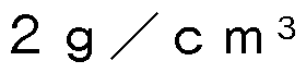 であった。
であった。
[0088] 〔微粒子の洗浄性能の評価〕
実施例 1及び比較例 1の洗浄用部材を基板洗浄装置に装着して、 シリコン ウェハの表面欠陥の数を計測することによって、 微粒子の洗浄性能を評価し た。 具体的な手順は、 シリコンウェハの仕上げ研磨、 洗浄用部材による洗浄 、 及び表面欠陥の測定の順に行った。 評価手順の詳細及び条件を以下に示す
[0089] < 1 . 仕上げ研磨 >
以下に示す組成の仕上げ研磨液と、 シリコンウェハとを用いて、 以下の研 磨条件でシリコンウェハの仕上げ研磨を行った。 シリコンウェハに対して市 版の研磨液を用いて粗研磨を行い、 その後、 以下に示す仕上げ研磨条件で仕 上げ研磨を行った。 粗研磨後のシリコンウェハのヘイズは、 2〜 3
 で あった。 ヘイズは、 1_八 丁㊀门〇〇 「社製 「3リ 「干 3〇 3门 3 9 1 装置を用いて測定される暗視野ワイ ド斜入射チャンネル (口 〇 ) での値である。
[0090] (仕上げ研磨液)
ヒドロキシェチルセルロース (ダイセル株式会社製、 3巳一4 0 0、 分子 量 2 5万) 、 ポリェチレングリコール ( 巳〇) 6 0 0 0 (重量平均分子量 6 0 0 0、 和光純薬工業株式会社製、 和光一級) 、 アンモニア水 (キシダ化 学株式会社製、 試薬特級) 、 シリカ粒子 (? !_ _ 3、 扶桑化学工業株式会社 製) 、 及びイオン交換水を混合して得られた研磨液濃縮液を、 使用直前にイ オン交換水で 4 0倍に希釈して、 仕上げ研磨液とした。 仕上げ研磨液におけ
\¥02020/175496 31 卩(:170? 2020 /007541
る組成は以下のとおりである。
ヒドロキシェチルセルロース: 0. 01質量%
P EG 6000 : 0. 0008質量%
シリカ粒子: 0. 1 7質量%
- アンモニア: 0. 01質量%
[0091] (シリコンウェハ)
単結晶シリコンウェハ (直径 200 mmのシリコン片面鏡面ウェハ、 伝導 型: P、 結晶方位: 1 00、 抵抗率: 0. 1 Q c m以上 1 00 Q c m未 満)
[0092] (仕上げ研磨条件)
研磨機:片面 8インチ研磨機 「GR I N D— X S P P 600 s」 (岡 本工作製)
-研磨パッ ド:スェードパッ ド (東レ コーテックス社製、 アスカー硬度 : 64、 厚さ : 1. 37 mm、 ナップ長: 450 m、 開口径: 60 /xm)
-シリコンウェハ研磨圧力: 1 00 g/c m2
-定盤回転速度: 60 r p m
-研磨時間: 5分
-仕上げ研磨液の供給速度: 1 50 g/m i n
-仕上げ研磨液の温度: 23°C
キャリア回転速度: 62 r p m
[0093] <2. 洗浄用部材による洗浄 >
仕上げ研磨後シリコンウェハに対して、 洗浄用部材による洗浄、 オゾン洗 浄及び希フッ酸洗浄を 1セッ トとして、 計 2セッ ト行った。 その後、 洗浄後 のシリコンウェハを 1 , 500 r pm、 2分間回転させて、 スピン乾燥を行 った。 各洗浄の条件は以下のとおりとした。
洗浄用部材による洗浄では、 600 「 で回転するシリコンウェハの中 央部に向かって、 超純水を流速 1 !_/ 丨 nで噴射しながら、 実施例又は比 較例の洗浄用部材をシリコンウェハの中央部から外周部へ移動させながら押
\¥0 2020/175496 32 卩(:170? 2020 /007541
し当てて、 該ウェハの一面を洗浄した。 洗浄時間は 1分間とした。
オゾン洗浄では、 6 0 0 「 01で回転するシリコンウェハの中央部に向か って、 2 0 のオゾンを含む常温 (2 3 °〇) のオゾン水を、 流速 1 !_ / nで 3分間噴射した。
希フッ酸洗浄では、 6 0 0 「 で回転するシリコンウェハの中央部に向 かって、 〇. 5質量%のフッ化水素アンモニウム (試薬特級、 ナカライテク ス株式会社製) を含む常温 (2 3 °〇 の水溶液を、 流速 1 !_ /〇! 丨 nで 6秒 間噴射した。
[0094] <3 . 表面欠陥の測定>
洗浄後のシリコンウェハの表面欠陥は、 <!_八 T e n c o r社製 「3リ 「干 3〇 3 1^ 3 1 — 0 1_ 3」 装置を用いて、 シリコンウェハ表面上に存 在する 4 5 n 以上 5 0 n 以下の粒径を有するパーティクル数を測定する ことによって評価した。 表面欠陥の評価結果は、 前記装置を用いて測定され る暗視野斜光ビームコンポジッ トチヤンネル (0(3 0) での値に基づいて評 価した。 この数値が小さいほど表面欠陥が少ないことを示す。
[0095] 実施例 1及び比較例 1の洗浄用部材を用いて洗浄したときのシリコンウェ ハの表面欠陥の発生数を、 図 5 (3) 及び (匕) に結果として示す。 図 5 ( a) では、 円で囲われた内側の黒色領域に白点が少ないほど表面欠陥の発生 が少なく、 微粒子の洗浄性能に優れていることを示している。
[0096] 図 5 (3) 及び (匕) に示すように、 実施例 1の洗浄用部材は、 比較例 1 のものと比較して、 シリコンウェハ表面の微粒子の残存が少なくなっており 、 表面欠陥の数が少なっていることが判る。 したがって、 本発明の洗浄用部 材は、 微粒子の洗浄性能に優れたものであり、 特に、 微粒子の効果的な除去 が望まれる基板等の精密電子部品の洗浄に好適なものである。
産業上の利用可能性
[0097] 本発明によれば、 洗浄対象面に付着した微粒子の洗浄性能に優れた洗浄用 部材が提供される。
Claims
[請求項 1 ] メジアン繊維径が 1 0 0门 01以上 2 0 0 0 n 以下である単繊維の 絡合によって保形されている不織構造体を備え、
前記不織構造体は、 見かけ密度が〇.
 6 0
6 0
9 /〇 01 3以下である、 洗浄用部材。
[請求項 2] 前記不織構造体は、 その空隙率が 3 0 %以上 7 5 %以下であり、 累積細孔容積を細孔径の対数値で微分した細孔容積分布において、
5 0 以下の細孔径の範囲にトップピークを有し、 且つ 5 〇 超 の細孔径の範囲にトップピークを有していない分布を有する、 請求項 1 に記載の洗浄用部材。
[請求項 3] 前記不織構造体が、 前記単繊維が絡合してなる堆積体の圧縮成形体 である、 請求項 1又は 2に記載の洗浄用部材。
[請求項 4] 支持部材を更に備え、
前記支持部材と前記不織構造体とが互いに接するように配されてい る、 請求項 1ないし 3のいずれか一項に記載の洗浄用部材。
[請求項 5] 前記不織構造体が、 前記支持部材の全面を被覆するように配されて いる、 請求項 4に記載の洗浄用部材。
[請求項 6] シート状又はバルク状の前記不織構造体が、 板状の前記支持部材の 少なくとも一つの面に配されている、 請求項 4に記載の洗浄用部材。
[請求項 7] シート状の前記不織構造体が、 口ール状の前記支持部材の周面に配 されている、 請求項 4に記載の洗浄用部材。
[請求項 8] 前記不織構造体がシート状であり、 該不織構造体に対する水滴の浸 透時間が 1分以内である、 請求項 1ないし 7のいずれか一項に記載の 洗浄用部材。
[請求項 9] 前記不織構造体がシート状であり、 該不織構造体に対する水滴の浸 透時間が 4 0秒以下である、 請求項 1ないし 8のいずれか一項に記載 の洗浄用部材。
[請求項 10] 前記単繊維が電界紡糸された繊維である、 請求項 1ないし 9のいず
\¥0 2020/175496 34 卩(:170? 2020 /007541
れか一項に記載の洗浄用部材。
[請求項 1 1 ] 前記単繊維は、 熱可塑性樹脂を含み、
前記熱可塑性樹脂は、 ポリエチレン、 ポリプロピレン、 エチレンー «—オレフィンコポリマー及びエチレンープロピレンコポリマーのポ リオレフィン樹脂、 ポリエチレンテレフタレートのポリエステル樹脂 、 ポリアミ ド 6及びポリアミ ド 6 6のポリアミ ド樹脂、 ポリ塩化ビニ ルやポリスチレンのビニル系樹脂、 並びにポリアクリル酸やポリメタ クリル酸メチルのアクリル系樹脂のうち少なくとも一種である、 請求 項 1ないし 1 0のいずれか一項に記載の洗浄用部材。
[請求項 12] 前記熱可塑性樹脂の含有量は、 前記単繊維の全構成成分 1 〇〇質量 部に対して、 7 0質量部以上 9 8質量部以下である、 請求項 1 1 に記 載の洗浄用部材。
[請求項 13] 前記単繊維はイオン性界面活性剤を含む、 請求項 1ないし 1 2のい ずれか一項に記載の洗浄用部材。
[請求項 14] 前記イオン性界面活性剤の含有量は、 前記単繊維の全構成成分 1 〇 〇質量部に対して、 2質量部以上 1 0質量部以下である、 請求項 1 3 に記載の洗浄用部材。
[請求項 15] 前記不織構造体の見かけ密度が、 〇.
 5 5
5 5
 以下である、 請求項 1ないし 1 4のいずれか一項に記載の 洗浄用部材。
[請求項 16] 前記不織構造体の空隙率が、 4 0 %以上 7 0 %以下である、 請求項
1ないし 1 5のいずれか一項に記載の洗浄用部材。
[請求項 17] 前記不織構造体の累積細孔容積が、 〇. 8 !_ / 9以上 2 0 !_ /
9以下である、 請求項 1ないし 1 6のいずれか一項に記載の洗浄用部 材。
[請求項 18] 請求項 1ないし 1 7のいずれか一項に記載の洗浄用部材の製造方法 であって、
電界紡糸用組成物の溶液又は溶融液を電場中に吐出し、 電界紡糸法
\¥0 2020/175496 35 卩(:170? 2020 /007541
によって紡糸して、 単繊維の堆積体を形成する工程と、
前記堆積体を押圧して、 見かけ密度が〇. 0 5 9 /〇〇! 3以上〇.
 洗浄用 部材の製造方法。
[請求項 19] 前記堆積体に、 1 0 1\1 /〇〇1 2以上1 0 0 0 0 0 1\1 /〇 01 2以下の 圧力を加えて、 圧縮成形体である不織構造体を形成する、 請求項 1 8 に記載の洗浄用部材の製造方法。
[請求項 20] 前記堆積体を一対のプレスロールの間に導入して、 シート状又は板 状の不織構造体を形成する、 請求項 1 8に記載の洗浄用部材の製造方 法。
[請求項 21 ] シート状の前記不織構造体で支持部材の外面を被覆する工程、 シー 卜状若しくは板状の前記不織構造体と支持部材とを積層する工程、 又 はシート状の不織構造体を支持部材の外面に巻きつける工程のうちい ずれかの工程を備え、 該不織構造体と該支持部材とを備えた洗浄用部 材を形成する、 請求項 1 8ないし 2 0のいずれか一項に記載の洗浄用 部材の製造方法。
[請求項 22] 前記不織構造体に対して加熱処理を行う、 請求項 1 8ないし 2 1の いずれか一項に記載の洗浄用部材の製造方法。
[請求項 23] 樹脂を含む前記電界紡糸用組成物を用いて電界紡糸法によって紡糸 して、 該樹脂を含む単繊維の堆積体を形成し、
前記堆積体を押圧して、 見かけ密度が〇. 0 5 9 /〇〇! 3以上〇.

前記不織構造体に対して、 前記樹脂の融点又は流動点を超えない温 度で加熱処理を行う、 請求項 1 8ないし 2 2のいずれか一項に記載の 洗浄用部材の製造方法。
Priority Applications (4)
| Application Number | Priority Date | Filing Date | Title |
|---|---|---|---|
| KR1020217025604A KR102433468B1 (ko) | 2019-02-28 | 2020-02-25 | 세정용 부재 및 그 제조 방법 |
| US17/433,843 US20220134386A1 (en) | 2019-02-28 | 2020-02-25 | Cleaning member, and method for manufacturing the same |
| SG11202108390RA SG11202108390RA (en) | 2019-02-28 | 2020-02-25 | Cleaning member, and method for manufacturing the same |
| CN202080016583.0A CN113473893B (zh) | 2019-02-28 | 2020-02-25 | 清洁用部件及其制造方法 |
Applications Claiming Priority (2)
| Application Number | Priority Date | Filing Date | Title |
|---|---|---|---|
| JP2019037024A JP6959280B2 (ja) | 2019-02-28 | 2019-02-28 | 洗浄用部材及びその製造方法 |
| JP2019-037024 | 2019-02-28 |
Publications (1)
| Publication Number | Publication Date |
|---|---|
| WO2020175496A1 true WO2020175496A1 (ja) | 2020-09-03 |
Family
ID=72239956
Family Applications (1)
| Application Number | Title | Priority Date | Filing Date |
|---|---|---|---|
| PCT/JP2020/007541 Ceased WO2020175496A1 (ja) | 2019-02-28 | 2020-02-25 | 洗浄用部材及びその製造方法 |
Country Status (7)
| Country | Link |
|---|---|
| US (1) | US20220134386A1 (ja) |
| JP (1) | JP6959280B2 (ja) |
| KR (1) | KR102433468B1 (ja) |
| CN (1) | CN113473893B (ja) |
| SG (1) | SG11202108390RA (ja) |
| TW (1) | TWI832977B (ja) |
| WO (1) | WO2020175496A1 (ja) |
Families Citing this family (1)
| Publication number | Priority date | Publication date | Assignee | Title |
|---|---|---|---|---|
| US20240308956A1 (en) * | 2022-09-09 | 2024-09-19 | Lawrence Livermore National Security, Llc | Lipophilic lithium salts for direct dissolution in organic scintillators |
Citations (6)
| Publication number | Priority date | Publication date | Assignee | Title |
|---|---|---|---|---|
| JP2006511315A (ja) * | 2002-11-13 | 2006-04-06 | ドナルドソン カンパニー,インコーポレイティド | ナノファイバー層を有する拭き取り材料 |
| JP2008055411A (ja) * | 2006-08-02 | 2008-03-13 | Toray Ind Inc | 洗浄加工布およびそれを用いた磁気記録媒体用基板表面の洗浄方法 |
| JP2008095226A (ja) * | 2006-10-11 | 2008-04-24 | Toray Ind Inc | シート状物およびその製造方法 |
| JP2009007713A (ja) * | 2007-06-29 | 2009-01-15 | Toray Ind Inc | シート状物 |
| WO2017212544A1 (ja) * | 2016-06-07 | 2017-12-14 | 株式会社フューエンス | ポリヒドロキシアルカン酸からなるナノファイバー構造体、および、不織布 |
| JP2018016907A (ja) * | 2016-07-28 | 2018-02-01 | 東レ株式会社 | ワイピングシート材およびその製造方法 |
Family Cites Families (6)
| Publication number | Priority date | Publication date | Assignee | Title |
|---|---|---|---|---|
| JP4454553B2 (ja) * | 2005-08-11 | 2010-04-21 | 花王株式会社 | 不織布 |
| JP5780040B2 (ja) * | 2010-08-31 | 2015-09-16 | 東レ株式会社 | 研磨布およびその製造方法 |
| JP6269922B2 (ja) * | 2013-08-29 | 2018-01-31 | Jnc株式会社 | 繊維シート及びこれを用いた繊維製品 |
| JP2016114745A (ja) * | 2014-12-15 | 2016-06-23 | 日本バイリーン株式会社 | 定着部用クリーニングシート、定着部用クリーニング材、及び定着部用クリーニング装置 |
| JP2017185422A (ja) * | 2016-04-01 | 2017-10-12 | Jnc株式会社 | デプスフィルター |
| JPWO2018025676A1 (ja) * | 2016-08-05 | 2019-05-30 | 王子ホールディングス株式会社 | 不織布シート |
-
2019
- 2019-02-28 JP JP2019037024A patent/JP6959280B2/ja active Active
-
2020
- 2020-02-25 US US17/433,843 patent/US20220134386A1/en not_active Abandoned
- 2020-02-25 CN CN202080016583.0A patent/CN113473893B/zh active Active
- 2020-02-25 KR KR1020217025604A patent/KR102433468B1/ko active Active
- 2020-02-25 WO PCT/JP2020/007541 patent/WO2020175496A1/ja not_active Ceased
- 2020-02-25 SG SG11202108390RA patent/SG11202108390RA/en unknown
- 2020-02-27 TW TW109106385A patent/TWI832977B/zh active
Patent Citations (6)
| Publication number | Priority date | Publication date | Assignee | Title |
|---|---|---|---|---|
| JP2006511315A (ja) * | 2002-11-13 | 2006-04-06 | ドナルドソン カンパニー,インコーポレイティド | ナノファイバー層を有する拭き取り材料 |
| JP2008055411A (ja) * | 2006-08-02 | 2008-03-13 | Toray Ind Inc | 洗浄加工布およびそれを用いた磁気記録媒体用基板表面の洗浄方法 |
| JP2008095226A (ja) * | 2006-10-11 | 2008-04-24 | Toray Ind Inc | シート状物およびその製造方法 |
| JP2009007713A (ja) * | 2007-06-29 | 2009-01-15 | Toray Ind Inc | シート状物 |
| WO2017212544A1 (ja) * | 2016-06-07 | 2017-12-14 | 株式会社フューエンス | ポリヒドロキシアルカン酸からなるナノファイバー構造体、および、不織布 |
| JP2018016907A (ja) * | 2016-07-28 | 2018-02-01 | 東レ株式会社 | ワイピングシート材およびその製造方法 |
Also Published As
| Publication number | Publication date |
|---|---|
| JP2020137896A (ja) | 2020-09-03 |
| TW202104706A (zh) | 2021-02-01 |
| TWI832977B (zh) | 2024-02-21 |
| KR20210110877A (ko) | 2021-09-09 |
| CN113473893B (zh) | 2022-10-28 |
| SG11202108390RA (en) | 2021-09-29 |
| CN113473893A (zh) | 2021-10-01 |
| US20220134386A1 (en) | 2022-05-05 |
| KR102433468B1 (ko) | 2022-08-18 |
| JP6959280B2 (ja) | 2021-11-02 |
Similar Documents
| Publication | Publication Date | Title |
|---|---|---|
| KR100627757B1 (ko) | 습윤 액체 및 수성 극성 액체를 이용한 섬유상 일렉트리트웹의 제조 방법 및 장치 | |
| KR101198490B1 (ko) | 정전 분무 장치 및 정전 분무 방법 | |
| JP7033233B2 (ja) | 電界紡糸装置及び繊維シートの製造方法 | |
| CN110392601A (zh) | 驻极体化片材及过滤器 | |
| KR20180033123A (ko) | 섬유 적층체 | |
| WO2020175496A1 (ja) | 洗浄用部材及びその製造方法 | |
| JP4298653B2 (ja) | ワイパー及びその製造方法 | |
| WO2017057148A1 (ja) | エレクトレットおよびエレクトレットフィルター | |
| JP6528243B2 (ja) | 不織布、空気清浄機、および不織布の製造方法 | |
| TWI839394B (zh) | 擦拭片材 | |
| JP7030542B2 (ja) | ワイピングシート | |
| CN114423894A (zh) | 无纺布、无纺布制造方法及过滤器 | |
| JP5310812B2 (ja) | 洗浄媒体およびこれを用いる乾式洗浄装置 | |
| JP7055009B2 (ja) | ワイピングシート及び清掃具 | |
| JP2021090659A (ja) | 湿式ワイピングシート | |
| JP2019070204A (ja) | 繊維の製造方法及び溶融電界紡糸用組成物 | |
| EP4214357B1 (en) | Nonwoven fibrous web | |
| JPH11276401A (ja) | 使い捨て掃除用積層シート | |
| JP7107831B2 (ja) | 溶融電界紡糸用組成物、並びに繊維及びその製造方法 | |
| JP6703393B2 (ja) | 清掃用シート及びその製造方法 | |
| JP2008088610A (ja) | 極細短繊維分散不織布及びその製造方法 | |
| JP2023069002A (ja) | 不織布の製造方法 | |
| JP2009241324A (ja) | クリーナ材 | |
| JP2019084294A (ja) | ワイピングシート | |
| JP2003311112A (ja) | エレクトレット濾過材 |
Legal Events
| Date | Code | Title | Description |
|---|---|---|---|
| 121 | Ep: the epo has been informed by wipo that ep was designated in this application |
Ref document number: 20762188 Country of ref document: EP Kind code of ref document: A1 |
|
| ENP | Entry into the national phase |
Ref document number: 20217025604 Country of ref document: KR Kind code of ref document: A |
|
| NENP | Non-entry into the national phase |
Ref country code: DE |
|
| 122 | Ep: pct application non-entry in european phase |
Ref document number: 20762188 Country of ref document: EP Kind code of ref document: A1 |