WO2020175328A1 - 電気絶縁材料、及び電気絶縁物品 - Google Patents
電気絶縁材料、及び電気絶縁物品 Download PDFInfo
- Publication number
- WO2020175328A1 WO2020175328A1 PCT/JP2020/006888 JP2020006888W WO2020175328A1 WO 2020175328 A1 WO2020175328 A1 WO 2020175328A1 JP 2020006888 W JP2020006888 W JP 2020006888W WO 2020175328 A1 WO2020175328 A1 WO 2020175328A1
- Authority
- WO
- WIPO (PCT)
- Prior art keywords
- pressure
- sensitive adhesive
- insulating material
- adhesive layer
- rubber
- Prior art date
- Legal status (The legal status is an assumption and is not a legal conclusion. Google has not performed a legal analysis and makes no representation as to the accuracy of the status listed.)
- Ceased
Links
Classifications
-
- H—ELECTRICITY
- H01—ELECTRIC ELEMENTS
- H01B—CABLES; CONDUCTORS; INSULATORS; SELECTION OF MATERIALS FOR THEIR CONDUCTIVE, INSULATING OR DIELECTRIC PROPERTIES
- H01B17/00—Insulators or insulating bodies characterised by their form
- H01B17/56—Insulating bodies
-
- C—CHEMISTRY; METALLURGY
- C09—DYES; PAINTS; POLISHES; NATURAL RESINS; ADHESIVES; COMPOSITIONS NOT OTHERWISE PROVIDED FOR; APPLICATIONS OF MATERIALS NOT OTHERWISE PROVIDED FOR
- C09J—ADHESIVES; NON-MECHANICAL ASPECTS OF ADHESIVE PROCESSES IN GENERAL; ADHESIVE PROCESSES NOT PROVIDED FOR ELSEWHERE; USE OF MATERIALS AS ADHESIVES
- C09J107/00—Adhesives based on natural rubber
-
- C—CHEMISTRY; METALLURGY
- C09—DYES; PAINTS; POLISHES; NATURAL RESINS; ADHESIVES; COMPOSITIONS NOT OTHERWISE PROVIDED FOR; APPLICATIONS OF MATERIALS NOT OTHERWISE PROVIDED FOR
- C09J—ADHESIVES; NON-MECHANICAL ASPECTS OF ADHESIVE PROCESSES IN GENERAL; ADHESIVE PROCESSES NOT PROVIDED FOR ELSEWHERE; USE OF MATERIALS AS ADHESIVES
- C09J109/00—Adhesives based on homopolymers or copolymers of conjugated diene hydrocarbons
-
- C—CHEMISTRY; METALLURGY
- C09—DYES; PAINTS; POLISHES; NATURAL RESINS; ADHESIVES; COMPOSITIONS NOT OTHERWISE PROVIDED FOR; APPLICATIONS OF MATERIALS NOT OTHERWISE PROVIDED FOR
- C09J—ADHESIVES; NON-MECHANICAL ASPECTS OF ADHESIVE PROCESSES IN GENERAL; ADHESIVE PROCESSES NOT PROVIDED FOR ELSEWHERE; USE OF MATERIALS AS ADHESIVES
- C09J121/00—Adhesives based on unspecified rubbers
-
- C—CHEMISTRY; METALLURGY
- C09—DYES; PAINTS; POLISHES; NATURAL RESINS; ADHESIVES; COMPOSITIONS NOT OTHERWISE PROVIDED FOR; APPLICATIONS OF MATERIALS NOT OTHERWISE PROVIDED FOR
- C09J—ADHESIVES; NON-MECHANICAL ASPECTS OF ADHESIVE PROCESSES IN GENERAL; ADHESIVE PROCESSES NOT PROVIDED FOR ELSEWHERE; USE OF MATERIALS AS ADHESIVES
- C09J201/00—Adhesives based on unspecified macromolecular compounds
-
- C—CHEMISTRY; METALLURGY
- C09—DYES; PAINTS; POLISHES; NATURAL RESINS; ADHESIVES; COMPOSITIONS NOT OTHERWISE PROVIDED FOR; APPLICATIONS OF MATERIALS NOT OTHERWISE PROVIDED FOR
- C09J—ADHESIVES; NON-MECHANICAL ASPECTS OF ADHESIVE PROCESSES IN GENERAL; ADHESIVE PROCESSES NOT PROVIDED FOR ELSEWHERE; USE OF MATERIALS AS ADHESIVES
- C09J7/00—Adhesives in the form of films or foils
- C09J7/20—Adhesives in the form of films or foils characterised by their carriers
-
- C—CHEMISTRY; METALLURGY
- C09—DYES; PAINTS; POLISHES; NATURAL RESINS; ADHESIVES; COMPOSITIONS NOT OTHERWISE PROVIDED FOR; APPLICATIONS OF MATERIALS NOT OTHERWISE PROVIDED FOR
- C09J—ADHESIVES; NON-MECHANICAL ASPECTS OF ADHESIVE PROCESSES IN GENERAL; ADHESIVE PROCESSES NOT PROVIDED FOR ELSEWHERE; USE OF MATERIALS AS ADHESIVES
- C09J7/00—Adhesives in the form of films or foils
- C09J7/30—Adhesives in the form of films or foils characterised by the adhesive composition
- C09J7/38—Pressure-sensitive adhesives [PSA]
-
- H—ELECTRICITY
- H01—ELECTRIC ELEMENTS
- H01B—CABLES; CONDUCTORS; INSULATORS; SELECTION OF MATERIALS FOR THEIR CONDUCTIVE, INSULATING OR DIELECTRIC PROPERTIES
- H01B3/00—Insulators or insulating bodies characterised by the insulating materials; Selection of materials for their insulating or dielectric properties
- H01B3/18—Insulators or insulating bodies characterised by the insulating materials; Selection of materials for their insulating or dielectric properties mainly consisting of organic substances
- H01B3/28—Insulators or insulating bodies characterised by the insulating materials; Selection of materials for their insulating or dielectric properties mainly consisting of organic substances natural or synthetic rubbers
-
- H—ELECTRICITY
- H01—ELECTRIC ELEMENTS
- H01B—CABLES; CONDUCTORS; INSULATORS; SELECTION OF MATERIALS FOR THEIR CONDUCTIVE, INSULATING OR DIELECTRIC PROPERTIES
- H01B3/00—Insulators or insulating bodies characterised by the insulating materials; Selection of materials for their insulating or dielectric properties
- H01B3/18—Insulators or insulating bodies characterised by the insulating materials; Selection of materials for their insulating or dielectric properties mainly consisting of organic substances
- H01B3/30—Insulators or insulating bodies characterised by the insulating materials; Selection of materials for their insulating or dielectric properties mainly consisting of organic substances plastics; resins; waxes
- H01B3/40—Insulators or insulating bodies characterised by the insulating materials; Selection of materials for their insulating or dielectric properties mainly consisting of organic substances plastics; resins; waxes epoxy resins
-
- H—ELECTRICITY
- H01—ELECTRIC ELEMENTS
- H01B—CABLES; CONDUCTORS; INSULATORS; SELECTION OF MATERIALS FOR THEIR CONDUCTIVE, INSULATING OR DIELECTRIC PROPERTIES
- H01B3/00—Insulators or insulating bodies characterised by the insulating materials; Selection of materials for their insulating or dielectric properties
- H01B3/18—Insulators or insulating bodies characterised by the insulating materials; Selection of materials for their insulating or dielectric properties mainly consisting of organic substances
- H01B3/48—Insulators or insulating bodies characterised by the insulating materials; Selection of materials for their insulating or dielectric properties mainly consisting of organic substances fibrous materials
- H01B3/50—Insulators or insulating bodies characterised by the insulating materials; Selection of materials for their insulating or dielectric properties mainly consisting of organic substances fibrous materials fabric
-
- H—ELECTRICITY
- H01—ELECTRIC ELEMENTS
- H01B—CABLES; CONDUCTORS; INSULATORS; SELECTION OF MATERIALS FOR THEIR CONDUCTIVE, INSULATING OR DIELECTRIC PROPERTIES
- H01B3/00—Insulators or insulating bodies characterised by the insulating materials; Selection of materials for their insulating or dielectric properties
- H01B3/18—Insulators or insulating bodies characterised by the insulating materials; Selection of materials for their insulating or dielectric properties mainly consisting of organic substances
- H01B3/48—Insulators or insulating bodies characterised by the insulating materials; Selection of materials for their insulating or dielectric properties mainly consisting of organic substances fibrous materials
- H01B3/52—Insulators or insulating bodies characterised by the insulating materials; Selection of materials for their insulating or dielectric properties mainly consisting of organic substances fibrous materials wood; paper; press board
Definitions
- the present invention relates to an electrically insulating material, and an electrically insulating article.
- Patent Document 1 discloses an adhesive tape that uses an adhesive containing microscopic hollow spheres (microballoons) such as glass and silica so that the dielectric constant of the insulating material is 2.5 or less. Is listed.
- Patent Document 1 Japanese Patent Laid-Open Publication No. 1 1-28 8 6 2 1
- an insulating material using an adhesive has a problem in that the adhesive force also decreases when the relative permittivity is lowered, and in an electronic device compatible with high-speed communication, the transmission loss is low. It is required to provide electrical insulating materials that have both good properties and adhesive properties.
- the present invention has been made to solve these problems in the prior art, and an object of the present invention is to provide an electric insulating material having a low transmission loss, and an electric insulating article.
- the inventors have found that an electrical insulation material with low transmission loss can be obtained by setting the porosity of the edge material to 30% by volume or more, and have completed the present invention.
- One aspect of the present invention includes a pressure-sensitive adhesive layer
- Adhesion strength of 180 degrees in a door is 3 1 ⁇ 1/2/0.01 or more, frequency It relates to an electric insulating material having a relative dielectric constant of 2 or less and a porosity of 30% by volume or more.
- the pressure-sensitive adhesive layer has a frequency of 1 It is preferable that the specific dielectric constant in the above is 2.7 or less.
- the pressure-sensitive adhesive layer preferably has a porosity of 0 to 75% by volume.
- the electrically insulating material may further include a base material.
- the base material has a frequency of 1
- the relative dielectric constant in the above is preferably 2.0 or less.
- the pressure-sensitive adhesive layer may include a rubber-based resin.
- the electrically insulating material has a tape shape and a thickness of ⁇ .
- One aspect of the present invention relates to an electrical insulation article including the electrical insulating material and a release liner.
- Fig. 1 is a top view schematically showing an electrically insulating material according to an embodiment of the present invention.
- FIG. 2 is a diagram schematically showing an electrically insulating material according to an embodiment of the present invention.
- FIG. 3 is a top view schematically showing an electrically insulating material according to an embodiment of the present invention. ⁇ 2020/175 328 3 ⁇ (:171? 2020 /006888
- FIG. 4 is a top view schematically showing an electrically insulating material according to an embodiment of the present invention.
- FIG. 5 is a schematic cross-sectional view showing a cross section taken along the line ___I′ of the electrically insulating material of FIG. 1.
- Figure 6 is an enlarged top view of the electrically insulating material of Figure 1.
- the electrical insulating material according to the present embodiment includes a pressure-sensitive adhesive layer and has a pulling rate of 3 ° at 23 °.
- Adhesive strength of 180 degree peeling is 31 ⁇ 1/20 ⁇ 101 or more, and circumference is 30% by volume or more.
- the relative permittivity in Nos. 2 and 2 is 2 or more and the porosity to be 30 vol% or more, it is possible to obtain an electrically insulating material exhibiting excellent adhesive strength and low transmission loss.
- the electrical insulating material according to the embodiment of the present invention has a 180 degree peel adhesive force of 31 ⁇ 1/20 ⁇ 101 or more at a tension rate of 300 ⁇ ! ⁇ !/01In at 23° ⁇ .
- the adhesive force of the electrical insulating material according to the embodiment of the present invention is an adhesive force to a stainless steel plate, which is used as an index indicating the degree of difficulty in peeling from the adherend during use. If the adhesive strength to the stainless steel plate is too low, it will peel off from the equipment, so it must be 31 ⁇ 1/20 ⁇ 101 or more, 41 ⁇ 1/20 ⁇ 101 or more is preferable, and ⁇ 1/2 The above is more preferable. Also, in order to prevent poor reworkability (removability) and anchorage with the base material, the adhesive strength is preferably 1 001 ⁇ !/20 or less, more preferably 501 ⁇ 1/20 ⁇ 101 or less. , 251 ⁇ 1/20 ⁇ 1 or less is more preferable, 201 ⁇ 1/20 ⁇ 1 ⁇ 1 or less is even more preferable, 1 5 Most preferred is [0020] (Relative permittivity)
- the electrical insulating material according to the embodiment of the present invention has a relative dielectric constant at a frequency of 1 MHz of 2 or less, preferably 1.8 or less, more preferably 1.5 or less, and 1.3
- the following is particularly preferable (usually 1.0 or more).
- the relative dielectric constant is preferably 1.00 or more, more preferably 1.01 or more, in order to prevent the electric insulating material from containing a relatively large amount of air and prevent the adhesive strength from being lowered and the base material from breaking. , 1.05 or more is more preferable, 1.10 or more is still more preferable, 1.20 or more is particularly preferable, and 1.27 or more is the most preferable.
- the relative dielectric constant of the electrically insulating material the value measured as described below can be used.
- a sample of electrically insulating material is sandwiched between a copper foil and an electrode, and the relative permittivity at a frequency of 1 MHz is measured with the following device.
- 3 samples of 30 mm x 30 mm sample were prepared, and the average of the measured values of these 3 samples was taken as the relative permittivity.
- the relative dielectric constant of the pressure-sensitive adhesive layer at a frequency of 1 MHz was measured under the following conditions according to JIS K 6911.
- Measurement method Capacity method (apparatus: A g i l e n t T e c h n o l o g i e s 4294 A P r e c i s i o n I m p e d a n c e A n a l y z e r)
- Electrode configuration 12.1 mmO, 0.5 mm thick aluminum plate
- the electrically insulating material according to the embodiment of the present invention has a porosity of 30% by volume or more. ⁇ 2020/175 328 5 ⁇ (: 171-1? 2020 /006888
- the electrical insulating material has a relative permittivity and a dielectric loss tangent derived from the material contained in it, but by setting the porosity of the electrical insulating material to 30% by volume or more, the relative permittivity of air (1.00) and the dielectric constant can be improved. It is possible to approach the tangent ( ⁇ . ⁇ ).
- the porosity of the electrically insulating material is preferably 30% by volume or more, more preferably 50% by volume or more. From the viewpoint of adhesive strength, it is usually preferably 75% by volume or less, more preferably 70% by volume or less, still more preferably 60% by volume or less.
- the porosity of the electrically insulating material containing no particles can be calculated from the porosity and the thickness of the material constituting the electrically insulating material.
- the electrically insulating material when the electrically insulating material is composed of only the pressure-sensitive adhesive layer, it can be calculated from the porosity and the thickness of the pressure-sensitive adhesive layer.
- the electrically insulating material when the electrically insulating material is composed of a pressure-sensitive adhesive layer and a base material, it can be calculated from the porosity and thickness of the pressure-sensitive adhesive layer and the base material.
- the density can be calculated by measuring the weight of the sample sheet of electrical insulating material cut out in X20 and dividing by the volume.
- the porosity of the pressure-sensitive adhesive layer and the base material is calculated by the following formulas (1) and (2) from the calculated porosity ⁇ % density ( ⁇ % density) and the sample sheet density (sample density). can do.
- the porosity of the pressure-sensitive adhesive layer containing the particles and the substrate can be calculated by the following formula (3).
- Porosity% (weight of particle [9] / specific gravity of particle) / ⁇ (weight of adhesive or base material [9] / specific gravity of adhesive or base material) 10 (weight of particle [9] / particle Specific gravity) ⁇ X 100 formula (3)
- the porosity (%) of the entire electric insulating material is calculated by using the above formulas (1) and (2) or ( It can be calculated by the following 3), and can be calculated by the following equation (4).
- Porosity (%) of the whole electric insulation material (8 3 + ⁇ 13) / (3 + 13) Formula (4 ⁇ 2020/175 328 6 ⁇ (:171? 2020 /006888
- the thickness of each layer is a value measured by a digital apply gauge (manufactured by Ozaki Manufacturing Co., Ltd.).
- the surface roughness of the pressure-sensitive adhesive layer is preferably 10 or less, more preferably 1 or less, still more preferably 0.5 or less, from the viewpoint of bondability to devices and the like.
- the surface roughness Can be measured by the method described in Examples, in accordance with “3.
- the electrically insulating material according to the present embodiment includes an adhesive layer.
- the structure of the electrically insulating material is not particularly limited, and may have a single-layer structure or a laminated structure.
- the electrically insulating material preferably comprises the pressure-sensitive adhesive layer. That is, the electrically insulating material may be a single layer body composed only of the adhesive layer made of the pressure-sensitive adhesive.
- the electrically insulating material may include at least one base material in addition to at least one pressure-sensitive adhesive layer.
- the electrically insulating material may have a laminated structure in which an adhesive layer is provided on one surface or both surfaces of the base material.
- the shape of the electrically insulating material according to the embodiment of the present invention is not particularly limited and any shape can be selected, for example, tape shape, film shape, sheet shape, plate shape, prismatic shape, etc. And a tape shape is preferable. Further, it may have a shape including a curved shape such as a winding body shape, a bent shape, and a curved shape. ⁇ 2020/175 328 7 ⁇ (: 171? 2020 /006888
- the thickness of the electrically insulating material according to the embodiment of the present invention is preferably 0.501 01 or less, more preferably 0.202 01 or less, in order to obtain a low relative dielectric constant. .1 The following is more preferable.
- the thickness of the electrically insulating material is It is preferably at least 0.01, more preferably at least 0.011, more preferably at least 0.04111111.
- the pressure-sensitive adhesive layer according to the embodiment of the present invention may have voids or may not have voids, but preferably has voids.
- the porosity of the pressure-sensitive adhesive layer according to the embodiment of the present invention can be appropriately set so that the porosity of the entire electrically insulating material is 30% by volume or more.
- As the pressure-sensitive adhesive layer a plurality of pressure-sensitive adhesive layers having different porosities can be used together.
- the porosity of the pressure-sensitive adhesive layer is 0% by volume or more, and the porosity of the pressure-sensitive adhesive layer having voids is preferably 40% by volume or more, and more preferably 50% by volume or more, from the viewpoint of reducing the relative dielectric constant. preferable. From the viewpoint of bondability to devices and the like, 75% by volume or less is preferable, and 60% by volume or less is more preferable.
- the porosity of the pressure-sensitive adhesive layer can be calculated by the above formulas (1) to (3).
- Examples of the method of setting the porosity of the pressure-sensitive adhesive layer in the above range include a method of forming the pressure-sensitive adhesive layer into a shape having voids, a method of containing hollow particles in the pressure-sensitive adhesive layer, and the like.
- the shape of the pressure-sensitive adhesive layer having voids is not particularly limited. For example, as shown in FIGS. 1 to 4, depending on the pressure-sensitive adhesive, dot-shaped (dot-shaped), stripe-shaped, wavy, grid-shaped, etc. Examples of the shape include a pattern formed in a random or random pattern, and a dot shape is preferable.
- FIGs. 1 to 4 are diagrams schematically showing an embodiment of an electrically insulating material.
- the point adhesive 12 is partially arranged on the surface of the base material 11 at regular intervals. ⁇ 2020/175 328 8 ⁇ (: 171? 2020 /006888
- the linear adhesive 22 is partially arranged on the surface of the base material 21 at regular intervals. As a result, the linear adhesive 22 has a striped pattern as a whole on the surface of the base material 21 to form an adhesive layer.
- the corrugated pressure sensitive adhesive 32 is partially arranged on the surface of the base material 31 at regular intervals.
- the wavy pressure-sensitive adhesive 32 forms a wavy pattern as a whole on the surface of the base material 31 to form the pressure-sensitive adhesive layer.
- the electrical insulating material 40 shown in FIG. 4 has a lattice-shaped pressure-sensitive adhesive 42 having a shape in which two stripe-shaped patterns intersect with each other.
- the lattice-shaped pressure-sensitive adhesive 42 has a lattice-shaped pattern as a whole on the surface of the base material 41 to form the pressure-sensitive adhesive layer.
- the size of the dot-shaped adhesive is not particularly limited, but it may be different for each dot-shaped adhesive. Or they may be the same.
- the size of the above-mentioned dot-like pressure-sensitive adhesive is preferably substantially the same from the viewpoint of stably obtaining properties such as adhesiveness.
- FIG. 1 shows an example of a hexagonal close-packed structure in which the adhesives 12 are arranged substantially evenly in a grid pattern, but of course, the present invention is not limited to this, and may be arranged in a square structure or the like. ..
- the size of the point adhesive is not particularly limited, but ⁇ 111 is preferable, more preferable is ⁇ 0.2111 to 4.0111111, and further preferable is ⁇ 0.3!!! to 3.5 ⁇ !!!.
- the size of the dot-like pressure-sensitive adhesive is 0.1111111 or more, sufficient adhesiveness to an adherend can be easily obtained, which is preferable.
- the size of the dot-like pressure-sensitive adhesive is not more than 5.0 because it becomes easy to obtain a low dielectric constant.
- the size of the dot adhesive is obtained by determining the area of the dot adhesive, obtaining a circle having the area from the area, and determining the circle as the diameter of the circle.
- the dot adhesive 12 has a circular shape, ⁇ 2020/175 328 9 ⁇ (:171? 2020 /006888
- the size of adhesive 12 corresponds to the diameter.
- the shape of the point adhesive is not particularly limited, but for example, a circular shape (for example, a perfect circle shape, an elliptical shape, a semicircular shape, a semielliptical shape, a 1/4 circular shape, a 1/4 oval shape, etc. , Fan shape, etc.), polygonal shape (eg, triangular shape, square shape, pentagonal shape, square shape, rectangular shape, trapezoidal shape, rhombus shape, etc.), boat shape, line shape, star shape, wedge shape, arrow shape , Comb shape, butterfly shape, irregular shape and the like.
- the shape of the point adhesive 12 of the electric insulating material 1 in FIG. 1 is circular.
- the shape of the above-mentioned dot-shaped adhesive is preferably a circular shape from the viewpoint of ease of forming the dot-shaped adhesive, productivity of the electrical insulating material, and transferability to parts.
- the shape of the dot adhesive is not particularly limited, but may be different or the same for each dot adhesive. It is preferable that the shapes of the above point-like pressure-sensitive adhesives are all substantially the same from the viewpoint of stably obtaining properties such as removability and adhesiveness.
- the widths of the linear pressure-sensitive adhesive 22, the wavy pressure-sensitive adhesive 32, and the grid-shaped pressure-sensitive adhesive 42 in Figs. 2 to 4 are determined by the desired voids as a whole in the electrical insulating materials 20, 30, and 40. It may be set so that the rate is obtained, and is not particularly limited, but from the viewpoint of securing the adhesive strength, it is preferably 0.01 111 ⁇ ! or more, more preferably 0.05 111 111 or more. , 111111 or more is more preferable. Also, The following is preferable, The following is more preferable, The following is more preferable.
- the width of the grid adhesive 42 is ⁇ / 1 in FIG.
- the intervals between the linear pressure-sensitive adhesives 22, the wavy pressure-sensitive adhesives 32, and the grid-shaped pressure-sensitive adhesives 42 are such that the desired porosity as a whole of the electrical insulating materials 20, 30, and 40 is high. It may be set so that it can be obtained, but it is not particularly limited, but it is preferably 0.02 0 101 or more, more preferably 0.0 4 0 0! 0! or more, and 1 111 111 or more. It is more preferable that there is. In addition, from the viewpoint of securing the adhesive strength, it is preferably 50,000! It is more preferable that It is more preferable that it is the following. ⁇ 2020/175 328 10 ⁇ (:171? 2020/006888
- the interval between the lattice-like adhesives 42 is ⁇ 2 in FIG.
- the pressure-sensitive adhesive in the electric insulating material When the pressure-sensitive adhesive in the electric insulating material is linear, it may extend in a direction intersecting (for example, orthogonal or oblique) with the longitudinal direction of the electric insulating material.
- Examples of the wavy shape include a curved shape such as a sine wave, a pseudo sine wave, and an arc wave, and a non-curved shape such as a zigzag shape and a triangular wave.
- the wavy pattern may be formed by stacking two or more waves of the same shape or different shapes with their phases shifted, or by inverting the shape or pattern.
- the shape of the pressure-sensitive adhesive of the electrically insulating material may be, for example, an arc shape, a circular shape, or an elliptical shape in addition to the above-mentioned wavy shape.
- Examples of the lattice shape include not only the orthorhombic lattice shown in Fig. 4 but also various lattice shapes such as a square lattice, a rectangular lattice, an orthorhombic lattice, and a triangular lattice.
- the lattice-shaped pattern may have a shape in which a plurality of stripe-shaped patterns intersect with each other, and the crossing angle (referred to as an acute angle side) of the plurality of stripe-shaped patterns is, for example, 10° to 90°, preferably It is in the range of 45 to 90 degrees, more preferably 60 to 90 degrees.
- the lattice pattern includes a pattern including a striped pattern composed of a plurality of linearly extending portions that repeatedly bend, for example, a pattern such as a hexagonal lattice. In such a pattern, adjacent linearly extending portions may be partially connected.
- the pressure-sensitive adhesive layer contains hollow particles
- hollow particles of acrylic type, rubber type, inorganic mineral type or the like can be added to the pressure-sensitive adhesive constituting the pressure-sensitive adhesive layer.
- the content of the hollow particles can be appropriately selected so that the porosity of the entire electrically insulating material is 30% by volume or more, and it is 4% by mass or more in the adhesive composition forming the adhesive. It is more preferably 5% by mass or more, further preferably 6% by mass or more. Further, from the viewpoint of securing the adhesive force, it is preferably 20% by mass or less, more preferably 15% by mass or less, and further preferably 10% by mass or less. ⁇ 2020/175 328 1 1 ⁇ (:171? 2020/006888
- the average particle size of the hollow particles can be appropriately selected in consideration of the thickness of the pressure-sensitive adhesive layer,
- it is 10 or more. Further, from the viewpoint of maintaining the adhesive strength, it is preferably 50 or less, more preferably 40 or less, and further preferably 30 or less.
- the average particle size of the hollow particles can be calculated by calculating the arithmetic mean from the particle sizes measured by a microscope for 50 randomly selected particles.
- the pressure-sensitive adhesive layer according to the embodiment of the present invention has a relative dielectric constant at a frequency of 1 IV!
- the relative permittivity of the pressure-sensitive adhesive layer is preferably 2.7 or less, more preferably 2.5 or less, and particularly preferably 2.3 or less (usually 1.0 or more).
- the relative dielectric constant of the pressure-sensitive adhesive layer As the relative dielectric constant of the pressure-sensitive adhesive layer, the value measured by the above method can be used.
- Examples of the pressure-sensitive adhesive forming the pressure-sensitive adhesive layer include known pressure-sensitive adhesives containing a base polymer.
- the base polymer is not particularly limited, and examples thereof include urethane polymers, acrylic polymers, rubber polymers, silicone polymers, polyester polymers, polyamide polymers, epoxy polymers, vinyl alkyl ether polymers, fluorine. Examples include polymers. Among them, an acrylic adhesive containing an acrylic polymer (acrylic resin) or a rubber adhesive containing a rubber polymer (rubber resin) is more preferable, and a rubber adhesive is particularly preferable. These adhesives can be used alone or in combination of two or more.
- the form of the pressure-sensitive adhesive is not particularly limited, and examples thereof include emulsion-type pressure-sensitive adhesives, solvent-type pressure-sensitive adhesives, hot-melt pressure-sensitive adhesives (hot-melt type pressure-sensitive adhesives), and active energy ray-curable pressure-sensitive adhesives.
- the pressure-sensitive adhesive layer may be a single layer or a multi-layer.
- Rubber-based adhesives include natural rubber, styrene-isoprene-styrene block copolymer, styrene-butadiene-styrene block copolymer, styrene-ethylene-butylene-styrene block copolymer, styrene-butadiene rubber, polybutadiene, polybutadiene It is based on rubber-based polymers such as isoprene, polyisobutylene, butyl rubber, chloroprene rubber, and silicone rubber.
- the rubber-based polymer is preferably a polymer that exhibits rubber elasticity in a temperature range around room temperature, and preferably includes an isoptylene-based polymer.
- Examples of the isoptylene polymer include those containing isoptylene as a constituent monomer.
- the isopylene-based polymer may be a homopolymer of isobutylene (polyisoptyrene, Mimi), which is a copolymer having isoptylene as a main monomer (that is, a copolymer in which isopylene is copolymerized at a ratio exceeding 50 mol%).
- copolymers include, for example, copolymers of isoptylene and normal butylene, copolymers of isoptylene and isoprene (for example, butyl rubbers such as regular butyl rubber, chlorinated butyl rubber, brominated butyl rubber and partially crosslinked butyl rubber). ), vulcanized products and modified products thereof (for example, products modified with a functional group such as a hydroxyl group, a carboxyl group, an amino group and an epoxy group).
- polyisoptyrene Tomomi
- Tomomi is preferable because it does not contain a double bond in the main chain and is excellent in weather resistance.
- the weight average molecular weight (IV!%) of the isoptylene polymer is not particularly limited.
- 1 ⁇ / 1 is about 1 XI ⁇ 4 or more appropriately selected and what. 1 above the upper limit of the ⁇ / 1 is not particularly limited, Ru obtained is at approximately 1 5 0 X 1 ⁇ 4 below.
- Elastic modulus of the pressure-sensitive adhesive from the viewpoint of cohesion, 1 ⁇ / 1 preferably approximately 2 X 1 ⁇ 4 or more, more preferably about 3 X 1 ⁇ 4 or more, more preferably approximately 5 X 1 ⁇ 4 or more ( for example approximately 7 XI ⁇ 4 or higher).
- the weight average content of the isoptylene polymer is ⁇ 2020/175 328 13 ⁇ (: 171? 2020 /006888
- the dispersity (IV!/1 ⁇ / ⁇ ) expressed as the ratio of the number average molecular weight (IV! n ) to the molecular weight is 3 to 7 (more preferably 3 to 6 and even more preferably 3.5 to 5.5). Those in the range of (4) can be preferably used.
- IV! refers to the standard polystyrene conversion value obtained by ⁇ (gel permeation chromatography).
- the content of the isoptylene-based polymer is preferably 30% by weight or more, more preferably 40% by weight or more, and 50% by weight in the rubber-based polymer. It is more preferable that the amount is at least the above, and 70% by weight is particularly preferable. Further, the upper limit value is not particularly limited and may be, for example, 100% by weight or less.
- the rubber-based pressure-sensitive adhesive composition may include a rubber-based polymer other than the isoptylene-based polymer.
- a rubber-based polymer other than the isoptylene-based polymer such as Styrene-Ethylene-Putylene-Styrene block copolymer (3 Mimi 3), Styrene-isoprene-Styrene block copolymer (3 3,), Styrene-Butagen-Styrene block copolymer (3m3), styrene-ethylene-propylene-styrene block copolymer (3m3, 3m3 hydrogenated product), styrene-ethylenepropene propylene block copolymer (3m, styrene-isoprene) Styrene-based block copolymers, such as styrene-isobutylene-styrene block copolymers (3 I, 3), styrene-butadiene rubber (3, [
- the content is 0% by weight or less, and it may not be contained (ie, 0% by weight).
- the content of the rubber-based base polymer is not particularly limited, but is preferably 20% by weight or more in the total solid content of the rubber-based adhesive composition,
- the content is more preferably 30% by weight or more, further preferably 40% by weight or more, and particularly preferably 50% by weight or more.
- the upper limit of the content of the rubber base polymer is not particularly limited and is preferably 100% by weight or less, more preferably 90% by weight or less.
- Acrylic adhesives are composed mainly of (meth)acrylic acid alkyl esters such as ethyl acrylate, butyl acrylate, 2-ethylhexyl acrylate, isooctyl acrylate, isononyl acrylate, and if necessary, acrylonitrile, vinyl acetate, Acrylic monomer based on styrene, methyl methacrylate, acrylic acid, maleic anhydride, vinylpyrrolidone, glycidyl methacrylate, dimethylaminoethyl methacrylate, hydroxyethyl acrylate, and acrylate.
- the main component is a polymer.
- the pressure-sensitive adhesive comprises: an alkyl (meth)acrylate (31) having 8 to 24 branched alkyl groups having 8 to 24 carbon atoms at the ester end and 8 to 24 carbon atoms. It is preferable to include a (meth)acrylic polymer obtained by polymerizing a monomer component containing an alkyl (meth)acrylate (32) having a linear alkyl group at the ester terminal.
- the alkyl (meth)acrylate means an alkyl acrylate and/or an alkyl methacrylate, and the term (meth) in the present invention has the same meaning.
- alkyl (meth)acrylate (31) having a branched alkyl group having 8 to 24 carbon atoms at the ester end alkylmethacrylate has a larger molar volume than alkylacrylate. It is preferable from the viewpoint of the effect of lowering the relative dielectric constant of the pressure-sensitive adhesive layer by lowering the dipole moment. ⁇ 2020/175 328 15 ⁇ (:171? 2020/006888
- alkyl (meth)acrylate (31) having an alkyl group having a branched chain having 8 to 24 carbon atoms at the ester terminal include, for example, 2-ethylhexyl acrylate (8 carbon atoms), Octyl acrylate (8 carbon atoms), Isononyl acrylate (9 carbon atoms), Isodecyl acrylate (10 carbon atoms), Isodecyl methacrylate (10 carbon atoms), Isomistyryl acrylate (14 carbon atoms), Isostearyl acrylate (C18), isoundecyl acrylate, isododecyl acrylate, isotridecyl acrylate, isopentadecyl acrylate, isohexadecyl acrylate, isoheptadecyl acrylate and the above methacrylate monomer It can be illustrated. These can be used alone or in combination of two or more.
- alkyl (meth)acrylate (32) having a linear alkyl group having 8 to 24 carbon atoms at the ester terminal alkylmethacrylate has an increase in molar volume and dipole than alkylacrylate. It is preferable from the viewpoint of the effect of lowering the relative dielectric constant of the pressure-sensitive adhesive layer by reducing the child moment.
- alkyl methacrylate having an alkyl group having 8 to 24 carbon atoms at the ester terminal examples include 1-1-octyl methacrylate (8 carbon atoms), -nonyl methacrylate (9 carbon atoms), lauryl methacrylate (carbon Number 12), Tridecyl Methacrylate (carbon number 13), Stearyl Methacrylate (carbon number 18), Undecyl Methacrylate (carbon number 11), Tetradecyl Methacrylate-Chain (carbon number 14), Pentadecyl Methacrylate (C 15), hexadecyl methacrylate (C 16), heptadecyl methacrylate (C 17), and the like. These can be used alone or in combination of two or more.
- an alkyl (meth)acrylate (31) having a branched alkyl group having 8 to 24 carbon atoms at the ester terminal and a linear alkyl group having 8 to 24 carbon atoms at the ester terminal
- the total proportion of alkyl (meth)acrylate (32) is based on the total monomer components forming the (meth)acrylic polymer. ⁇ 2020/175 328 16 ⁇ (:171? 2020 /006888
- the monomer component forming the (meth)acrylic polymer further contains at least one functional group-containing monomer selected from a carboxylic group-containing monomer, a hydroxyl group-containing monomer and a monomer having a cyclic ether group. Can be included.
- these pressure-sensitive adhesive compositions may contain other known additives, such as colorants, powders such as pigments, dyes, surfactants, plasticizers, polymerization initiators, and tackiness agents.
- Giving agent, surface lubricant, leveling agent, softening agent, antioxidant, anti-aging agent, light stabilizer, UV absorber, polymerization inhibitor, inorganic or organic filler, metal powder, particles, foil It can be appropriately added depending on the intended use of the product.
- the kind, combination, addition amount and the like of the additives added to the pressure-sensitive adhesive composition can be appropriately set according to the purpose.
- the content (total amount) of the additives in the pressure-sensitive adhesive composition is preferably 30% by weight or less, more preferably 20% by weight or less, and further preferably 10% by weight or less. Not good.
- the pressure-sensitive adhesive layer can be formed, for example, by applying the pressure-sensitive adhesive composition to a support and drying and removing the polymerization solvent.
- one or more solvents other than the polymerization solvent may be newly added as appropriate.
- Various methods are used as a method for applying the pressure-sensitive adhesive composition. Specifically, for example, mouth coat, kiss roll coat, gravure coat, reverse coat, mouth brush, spray coat, dip roll coat, bar coat, knife coat, air knife coat, force ten coat, lip coat, die coater, etc. Extrusion coating method and the like.
- Examples of the method for providing the point adhesive 12 shown in Fig. 1 as an adhesive layer include, for example, a method of dropping the adhesive composition obtained by using a dispenser and a gravure roll having a formed pattern.
- general printing techniques such as screen printing, offset printing and flexo printing can be preferably used.
- Examples of the method for providing the linear adhesive 22 shown in FIGS. 2 to 4, the wavy adhesive 32, and the lattice adhesive 42 as an adhesive layer include screen printing, slot die coating, and other screen printing.
- General printing techniques such as printing, offset printing and flexo printing can be used favorably.
- the lattice-shaped adhesive 42 may be formed by stacking two or more kinds of linear adhesives with their directions shifted.
- the thickness (height) of the pressure-sensitive adhesive in the case of forming a pattern with the pressure-sensitive adhesive is not particularly limited, but may be different or the same for each pressure-sensitive adhesive.
- the thickness of the pressure-sensitive adhesive is preferably substantially the same from the viewpoint of stably obtaining properties such as adhesiveness.
- the thickness of the pressure-sensitive adhesive layer is not particularly limited, but is preferably 5 or more, more preferably 100! or more. Further, it is preferably 800 or less and more preferably 50 or less. The thickness of the adhesive layer is 5 If it is above, it is possible to bond by following the minute irregularities. ⁇ 2020/175 328 18 ⁇ (: 171? 2020 /006888
- the thickness of the pressure-sensitive adhesive layer can be measured with a digital apply gauge (manufactured by Ozaki Seisakusho Co., Ltd.) as described above.
- the thickness of the pressure-sensitive adhesive layer means the thickness of the largest portion of the pressure-sensitive adhesive in the height direction.
- the thickness of the adhesive layer of the electrically insulating material 1 corresponds to the height II.
- the heating and drying temperature is preferably about 30° to 200°°, more preferably 40° to 180°°, and further preferably 80° to 160°°. ..
- the heating temperature is preferably about 30° to 200°°, more preferably 40° to 180°°, and further preferably 80° to 160°°. ..
- the drying time an appropriate time can be appropriately adopted.
- the drying time is preferably about 5 seconds to 20 minutes, more preferably 30 seconds to 10 minutes, still more preferably 1 minute to 8 minutes.
- the pressure-sensitive adhesive layer can be formed by irradiating with active energy rays such as ultraviolet rays.
- active energy rays such as ultraviolet rays.
- the material for forming the base material can be appropriately selected so that the porosity of the entire electrically insulating material is 30% by volume or more.
- polyethylene Polyolefin film such as polypropylene, ethylene-propylene copolymer, etc.
- Polyester film such as polyethylene terephthalate
- Plastic film such as polyvinyl chloride, polytetrafluoroethylene
- Kraft paper Japanese paper, etc.
- Cotton cloth, suf cloth Cloths such as polyester woven cloth, vinylon cloth woven cloth and the like
- metal foil for example, polyethylene, Polyolefin film such as polypropylene, ethylene-propylene copolymer, etc.
- Polyester film such as polyethylene terephthalate
- Plastic film such as polyvinyl chloride, polytetrafluoroethylene
- Kraft paper Japanese paper, etc.
- Cotton cloth suf cloth Cloths such as polyester woven cloth, vinylon cloth woven cloth and the like
- metal foil metal foil.
- a foamed sheet can be used as the base material to adjust the porosity of the electrically insulating material to a desired range. ⁇ 2020/175 328 19 ⁇ (:171? 2020 /006888
- the substrate may or may not have voids, and a plurality of substrates having different void ratios can be used together. ..
- the porosity (volume basis) of the base material is not particularly limited, and can be appropriately set so that the porosity of the entire electrically insulating material including the adhesive layer and the base material is 30% by volume or more. ..
- the porosity of the base material having voids is preferably 50% by volume or more, and more preferably 60% by volume or more. From the viewpoint of interlayer strength, 90% by volume or less is preferable, and 80% by volume or less is more preferable.
- the porosity of the substrate can be calculated by the above formulas (1) to (4).
- the relative permittivity of the pressure-sensitive adhesive layer is particularly preferably 5 or less (usually 1.0 or more).
- the relative dielectric constant of the base material a value measured by the same method as the relative dielectric constant of the electric insulating material as described above can be used.
- the base material is preferably obtained from a resin composition containing at least a resin and, if necessary, powder particles and additives.
- a foamed sheet (foamed body) obtained by foaming a resin composition may be used as the substrate.
- the resin composition as the raw material of the base material is not particularly limited, but it is preferable that the resin composition contains a thermoplastic resin from the viewpoint of moldability (ease of making a foam) and recyclability.
- Thermoplastic resins include polyolefin resins, polyvinyl chloride resins, polyester resins, polystyrene resins, polyvinyl acetate resins, acrylic resins ⁇ 2020/175 328 20 ⁇ (: 171-1? 2020 /006888
- thermoplastic resins can be used alone or in combination of two or more kinds.
- polyolefin resins are preferably used because of their relatively low relative permittivity and dielectric loss tangent.
- the polyolefin resin is not particularly limited, and examples thereof include low density polyethylene, medium density polyethylene, high density polyethylene, linear low density polyethylene, polypropylene, a copolymer of ethylene and propylene, ethylene or ethylene. Copolymers of propylene with other ⁇ -olefins (eg butene-1, pentene-1, hexene-1, 4-methylpentene-1 etc.), ethylene and other ethylenically unsaturated monomers (eg vinyl acetate, Acrylic acid, acrylic acid ester, methacrylic acid, methacrylic acid ester, vinyl alcohol, etc.) and the like. Further, the polyolefin-based resin may be used alone or in combination of two or more kinds. When the polyolefin resin is a copolymer, it may be a random copolymer or a block copolymer.
- ⁇ -olefins eg butene-1, pentene-1, hexene-1,
- the polyolefin resin a resin having a wide molecular weight distribution and having a shoulder on the high molecular weight side, a slightly crosslinked type resin (slightly crosslinked type resin), a long chain branched type resin, or the like is used. It is preferable.
- a rubber component and/or a thermoplastic elastomer component may be used in the resin composition together with the thermoplastic resin.
- a rubber component and/or a thermoplastic elastomer component flexibility is imparted in the surface direction, and wrinkles are less likely to occur even when the communication sheet structure is formed, even if it is bent or rolled into a mouth.
- the ratio of the rubber component and/or the thermoplastic elastomer component is not particularly limited.
- thermoplastic resin and the rubber component and/or the thermoplastic elastomer component the rubber component and/or the thermoplastic elastomer is mixed. ⁇ 2020/175 328 21 ⁇ (:171? 2020 /006888
- the proportion of the storm component is less than 1% by weight, the flexibility of the resin composition when formed into a foamed sheet tends to decrease, while if it exceeds 99% by weight, gas loss tends to occur during foaming. However, it becomes difficult to obtain a highly foamable foam.
- the rubber component or the thermoplastic elastomer component is not particularly limited as long as it has rubber elasticity and is preferably foamable, and examples thereof include natural rubber, polyisobutylene, polyisoprene, chloroprene rubber, butyl rubber and nitrile rubber. Natural or synthetic rubbers such as ruptyl rubber; ethylene-propylene copolymers, ethylene-propylene-propylene copolymers, ethylene-vinyl acetate copolymers, olefinic elastomers such as polybutene and chlorinated polyethylene; styrene-butadiene.
- Examples thereof include styrene elastomers such as styrene copolymers, styrene-isoprene-styrene copolymers, and hydrogenated products thereof; polyester elastomers; polyamide elastomers; various thermoplastic elastomers such as polyurethane elastomers.
- These rubber components or thermoplastic elastomer components may be used alone or in combination of two or more.
- These rubber components and thermoplastic elastomer components for example, have a glass transition temperature of room temperature or lower (for example, 20 ° ⁇ or lower), and therefore, a polyolefin resin foam having a rubber component or a thermoplastic elastomer component as a base material is used. When used, the flexibility and shape-following property can be significantly improved.
- an olefinic elastomer can be preferably used as the rubber component and/or the thermoplastic elastomer component.
- the olefin elastomer generally has a structure in which the olefin resin component and the ethylene-propylene rubber are microphase-separated, and has good compatibility with the polyolefin resin.
- the resin composition used for forming the base material is a foam
- the resin composition further contains powder particles. That is, the resin composition used for foam molding preferably contains a thermoplastic resin and powder particles.
- the powder particles can function as a foam nucleating agent during foam molding. Therefore, by blending powder particles, resin foam in a good foamed state can be obtained. ⁇ 0 2020/175 328 22 ⁇ (: 17 2020 /006888
- a foam can be obtained. If powder particles are used in the resin composition and a supercritical fluid is used as the high-pressure gas, which is a foaming agent used for foaming the resin composition, a resin foam having particularly fine and uniform cells is obtained. be able to
- powder particles examples include talc, silica, alumina, zeolite, calcium carbonate, magnesium carbonate, barium sulfate, zinc oxide, titanium oxide, aluminum hydroxide, magnesium hydroxide, mica, montmorillonite. Clay, force-bon particles, glass fiber, force-bon tube, etc. can be used.
- the powder particles can be used alone or in combination of two or more kinds.
- the amount of the powder particles is not particularly limited, but for example, 5 to 150 parts by weight, preferably 10 parts by weight, relative to 100 parts by weight of the resin component (polymer component) in the resin composition. To 130 parts by weight, and more preferably 20 to 120 parts by weight can be appropriately selected. If the amount of powder particles is less than 5 parts by weight with respect to 100 parts by weight of the resin component (polymer component), it will be difficult to obtain a uniform foam, while 150 parts by weight will be added. If it exceeds the above range, the viscosity of the resin composition will remarkably increase, and outgassing will occur during foam formation, which may impair the foaming characteristics.
- the average particle size of the powder particles is not particularly limited, but is, for example, about 0.1 to 10, preferably about 0.5 to 5. If the average particle size of the powder particles is less than 0.1, it may not function sufficiently as a nucleating agent, and if the average particle size exceeds 10, it may cause outgassing during foam molding.
- the resin composition has a characteristic of being easily burned (of course, it is also a drawback). Therefore, when flame retardancy is required to be added to the base material in which the resin composition is used, as powder particles, powder particles having flame retardancy (for example, various powdery flame retardants) Is preferably blended.
- the flame retardant can be used together with powder particles other than the flame retardant.
- an inorganic flame retardant is suitable.
- an inorganic flame retardant ⁇ 2020/175 328 23 ⁇ (:171? 2020 /006888
- a brominated flame retardant May be, for example, a brominated flame retardant, a chlorine flame retardant, a phosphorus flame retardant, an antimony flame retardant, etc.
- chlorine flame retardants and brominated flame retardants are not harmful to the human body during combustion. It generates gas components that are corrosive to equipment, and since phosphorus-based flame retardants and antimony-based flame retardants have problems such as toxicity and explosiveness, non-halogen- and non-antimony-based inorganic flame retardants are used. It can be preferably used.
- non-halogen/non-antimony inorganic flame retardants include aluminum hydroxide, magnesium hydroxide, magnesium oxide/nickel oxide hydrate, magnesium oxide/zinc oxide hydrate, and other hydrated metal compounds. Be released. The hydrated metal oxide may be surface-treated.
- the flame retardants can be used alone or in combination of two or more.
- the amount of the flame retardant used is not particularly limited, and is, for example, 8 to 70% by weight, preferably 25 to 65% by weight based on the total amount of the resin composition. It can be appropriately selected. If the amount of the flame retardant used is too small, the flame retarding effect becomes small, while if it is too large, it becomes difficult to obtain a highly foamed foam.
- the resin composition according to the embodiment of the present invention may further contain an aliphatic compound.
- Aliphatic compounds have high crystallinity, and when added to a polyolefin resin, they form a strong film on the resin surface, so the resin walls that form the cells may function to prevent them from blocking each other. Bubbles in the body are less likely to be trapped and shape recovery is improved.
- the aliphatic compound at least one selected from fatty acids, fatty acid amides, and fatty acid metal soaps can be used. Those containing a highly polar functional group are less likely to be compatible with the polyolefin-based resin, so that they are easily deposited on the resin surface, and the above-mentioned effects are easily exhibited.
- the melting point of the aliphatic compound is preferably 50 to 150°°, from the viewpoints of lowering the molding temperature, suppressing deterioration of the polyolefin resin composition, imparting sublimation resistance, and the like. Is 70 to 100 ° ⁇ .
- the above-mentioned fatty acid has about 18 to 38 carbon atoms (more preferably 18 to 2 carbon atoms).
- Examples include 12-hydroxystearic acid. Among them, behenic acid is special. ⁇ 2020/175 328 24 ⁇ (: 171-1? 2020 /006888
- the fatty acid amide is preferably a fatty acid amide having a carbon number of the fatty acid portion of about 18 to 38 (more preferably 18 to 22), and may be either a monoamide or a bisamide. Specific examples include stearic acid amide, oleic acid amide, erucic acid amide, methylenebisstearic acid amide, ethylenebisstearic acid amide, and the like. Among them, erucic acid amide is particularly preferable.
- fatty acid metal soaps include salts of the above fatty acids such as aluminum, calcium, magnesium, lithium, barium, zinc, and lead. Fatty acids and fatty acid amides are particularly preferable as the aliphatic compound.
- the content of the aliphatic compound is, for example, 1 to 20 parts by weight, and preferably 5 to 15 parts by weight, based on 100 parts by weight of the resin component (polymer component) in the resin composition. , And more preferably 8 to 13 parts by weight. If the content of the aliphatic compound is less than 1 part by weight, a sufficient amount of the component is not deposited on the resin surface, and it becomes difficult to obtain the shape recovery effect. On the other hand, if the amount exceeds 20 parts by weight, the resin becomes plastic and cannot maintain a sufficient pressure in the extruder, and the content of the blowing agent such as carbon dioxide in the resin decreases, resulting in a high expansion ratio. However, it is difficult to obtain a foam having a sufficient foam density.
- the resin composition used for the substrate may contain various additives, if necessary.
- the type of additive is not particularly limited, and for example, various additives commonly used in foam molding can be used. Specifically, as additives, bubble nucleating agents, crystal nucleating agents, plasticizers, lubricants, colorants (pigments, dyes, etc.), ultraviolet absorbers, antioxidants, antioxidants, fillers, reinforcing agents, Antistatic agents, surfactants, tension modifiers, anti-shrinkage agents, fluidity modifiers, clays, vulcanizing agents, surface treatment agents, flame retardants in various forms other than powder, dispersion aids, polyolefin resins Examples include modifiers.
- the addition amount of the additive can be appropriately selected within a range that does not impair the formation of bubbles and the like, and the addition amount used in usual molding of a thermoplastic resin can be adopted.
- the substrate is formed by foaming the resin composition using the resin composition as a raw material, ⁇ 2020/175 328 25 ⁇ (: 171-1? 2020 /006888
- It may be a resin foam.
- the base material is preferably a foam containing cells.
- the foam is preferably a foam sheet having a high expansion ratio (low density) containing a large amount of fine bubbles.
- the base material has a relative dielectric constant and a dielectric loss tangent derived from the material contained in the base material.
- the relative dielectric constant of air (1. 00) and the dielectric loss tangent (0. ) Can be approached.
- the content thereof should be increased, that is, the expansion ratio should be increased (the density should be decreased).
- simply reducing the density lowers the mechanical properties such as strength and flexibility of the foamed sheet, so in order to maintain this, many fine bubbles containing a small average cell diameter are contained. It is desirable that the foam is a foam.
- the base material has a density of 0. 1 to 2. ⁇ .
- a low dielectric loss tangent and relative permittivity can be obtained by setting the following: With the above, sufficient strength as a base material can be obtained.
- the density of the above-mentioned base material can be obtained from the following formula by punching out the base material to obtain a test piece, determining the volume and mass of the test piece.
- the average cell diameter of the cells is preferably 1 to 300, ⁇ 200 is more preferred, and ⁇ 100 is particularly preferred. If the average cell diameter exceeds 300, shape retention (strength of foam) may decrease, and if it is less than 1, sufficient porosity cannot be obtained, making it difficult to obtain low dielectric loss tangent and relative dielectric constant. There is a case.
- the average cell diameter can be determined by analyzing an enlarged image of the foam with image analysis software.
- the method for producing such a resin foam is not particularly limited. ⁇ 2020/175 328 26 ⁇ (:171? 2020 /006888
- the base material when the structure of the base material is a laminated structure, the base material may be composed of, for example, a laminated structure of a non-foamed layer made of the resin composition, or made of the resin foam.
- the resin foam may have a laminated structure of a foamed layer, or a laminated structure of a non-foamed layer made of the resin composition and a foamed layer made of the resin foam. It is preferable that the structure includes a foam layer.
- the total number of layers, the number of foam layers made of a resin foam, the number of non-foam layers, the thickness of each layer, etc. are appropriately selected according to the application.
- the non-foamed layer is not particularly limited as long as it does not have a foamed structure (cell structure) in the layer.
- the resin composition may have an appropriate shape (for example, sheet shape, film shape, etc.).
- the layer include an unfoamed resin molded body produced by molding.
- the non-foamed layer can be used alone or in combination of two or more kinds.
- the thickness of the base material is not particularly limited and can be appropriately selected so that the porosity of the entire electrically insulating material is 30% by volume or more. Further, it is appropriately selected depending on the use, shape, form, etc. of the electrically insulating material.
- the thickness of the base material is, for example, ⁇ .
- the electrically insulating article according to the embodiment of the present invention includes an electrically insulating material and a release liner.
- the electrically insulating material may protect the pressure-sensitive adhesive layer with a release-treated sheet (release liner) until practical use. In practice, peel off the release-treated sheet. ⁇ 2020/175 328 27 ⁇ (: 171? 2020 /006888
- Examples of the constituent material of the release liner include porous materials such as plastic film, paper, cloth, and non-woven fabric, nets, foam sheets, metal foils, and appropriate thin sheets such as laminated bodies. Etc. can be mentioned.
- a plastic film is preferably used because it has excellent surface smoothness.
- plastic film examples include polyethylene film, polypropylene film, polybutene film, polybutadiene film, polymethylpentene film, polyvinyl chloride film, vinyl chloride copolymer film, polyethylene terephthalate film, and polyethylene.
- plastic film examples include polyethylene film, polypropylene film, polybutene film, polybutadiene film, polymethylpentene film, polyvinyl chloride film, vinyl chloride copolymer film, polyethylene terephthalate film, and polyethylene.
- examples thereof include terephthalate film, polyurethane film, ethylene-vinyl acetate copolymer film and the like.
- the thickness of the release liner is usually 5 to 200, preferably about 5 to 100.
- the release liner may include a silicone-based, fluorine-based, long-chain alkyl-based or fatty acid amide-based release agent, release and antifouling treatment with silica powder, and a coating type, if necessary.
- An antistatic treatment such as a kneading type or a vapor deposition type can also be performed.
- the release property from the pressure-sensitive adhesive layer can be further improved by appropriately performing a release treatment such as a silicone treatment, a long-chain alkyl treatment or a fluorine treatment on the surface of the release liner.
- the electrically insulating material of the present embodiment has excellent adhesive strength and has a low relative permittivity, so that transmission loss (decrease in communication performance) in a high frequency region can be reduced, and devices and articles for transmitting and receiving electromagnetic waves and It is preferable to use it for such parts.
- structural parts for vehicles, on-board products, housings for electronic devices, housings for home appliances, structural parts, mechanical parts, various automotive parts, parts for electronic devices, furniture, kitchen appliances, etc. Medical equipment, parts of building materials, and other structural parts and exterior parts.
- instrument panels console boxes, door knobs, door trims, shift gears/pedals, pedals, glove boxes.
- S bumpers, bonnets, fenders, trunks, doors, roofs, pillars, seats, steering wheels, ECU boxes, electrical components, engine peripherals, drive system/gear peripherals, intake/exhaust system parts, cooling system parts Etc.
- electronic appliances and home appliances include refrigerators, washing machines, vacuum cleaners, microwave ovens, air conditioners, lighting equipment, electric water heaters, televisions, watches, ventilation fans, projectors, speakers and other home appliances, personal computers, mobile phones.
- This includes electronic information devices such as telephones, smartphones, digital cameras, tablet PCs, portable music players, portable game consoles, chargers and batteries.
- Each sample was sandwiched between a copper foil and an electrode, and the relative permittivity at a frequency of 1 MHz was measured by the following device.
- 3 samples of 30 mm x 30 mm were prepared, and the average of the measured values of these 3 samples was taken as the relative permittivity.
- the relative permittivity of the pressure-sensitive adhesive layer at a frequency of 1 MHz was measured under the following conditions according to JIS K 6911.
- Measurement method Capacity method (apparatus: A g i l e n t T e c h n o l o g i e s 4294 A P r e c i s i o n I m p e d a n c e A n a l y z e r)
- Electrode configuration 12.1 mmO, 0.5 mm thick aluminum plate
- the split density was calculated by.
- the porosities of the pressure-sensitive adhesive layer and the substrate were calculated by the following formulas (1) and (2) from the calculated porosity density of ⁇ % ( ⁇ density) and sample density (sample density), respectively.
- the porosity of the pressure-sensitive adhesive layer containing the particles and the substrate was calculated by the following equation (3).
- Porosity% (weight of particles [9] / specific gravity of particles) / ⁇ (weight of adhesive or base material [9] / specific gravity of adhesive or base material) 10 (weight of particles [9] / particle Specific gravity) ⁇ X 100 formula (3)
- the porosity (%) of the entire electrically insulating material is calculated by the following formula (4) by calculating the porosity of the adhesive layer and the base material by the above formulas (1) and (2) or (3), respectively. I put it out.
- the release film of the electrically insulating material was peeled off, and the surface roughness (83) of the pressure-sensitive adhesive layer was measured.
- the surface roughness (83) of the pressure-sensitive adhesive layer was measured.
- use a N73300 Non-contact three-dimensional roughness measuring device, manufactured by Viko Co., Ltd. of Japan
- observe in the range of 200101 x 200101 and measure in the direction perpendicular to the coating direction of the adhesive layer. Every 3 points of surface roughness was measured.
- Tables 1 to 5 show the measured surface roughness. The average value of is shown.
- the release film on one side was peeled off, and an adhesive tape having a thickness of 25 and a total thickness of 53 was used as a base material. (Nitto Denko Co., Ltd. "
- a rubber-based pressure-sensitive adhesive composition having a solid content concentration of 25 mass% was prepared by dissolving the compounded compound in a mass ratio of 50 in toluene.
- An acrylic polymer solution having an amount of 1300,000 was obtained.
- 2 parts by mass of an isocyanate type cross-linking agent manufactured by Nippon Polyurethane Co., Ltd., Coronate!-
- an acrylic adhesive composition was prepared. (Solid content concentration 32% by mass) was prepared.
- the release treated surface under the trade name "Diafoyl 1 ⁇ /1[3 ⁇ 4 38" (manufactured by Mitsubishi Kagaku Polyester Film Co., Ltd.) was used.
- hollow particles prepared by adding Matsumotomic Microspheres (manufactured by Matsumoto Yushi-Seiyaku Co., Ltd.) as hollow particles to the rubber-based pressure-sensitive adhesive composition at 9% by mass were prepared.
- a rubber-based pressure-sensitive adhesive composition containing particles was manufactured under the trade name "Release Film Mitsunichi 75- 8" (manufactured by Fujiko Co., Ltd.) on the release-treated surface so that the thickness of the adhesive layer after drying is as shown in Table 1 and then dried at 120°° for 3 minutes. Layers were formed to obtain the electrically insulating material of Example 4.
- the release treated surface under the trade name "Diafoyl 1 ⁇ /1[3 ⁇ 4 38" (manufactured by Mitsubishi Kagaku Polyester Film Co., Ltd.) was used.
- the rubber-based adhesive composition prepared above was applied to the entire surface on one side of a polyolefin film (trade name: Volara XI -_1 ⁇ 1 #03001) (manufactured by Sekisui Chemical Co., Ltd.) as a base material after drying.
- the thickness and density of the layers are those listed in Table 1. ⁇ 2020/175 328 32 ⁇ (: 171? 2020 /006888
- the release treated surface under the trade name "Diafoyl 1 ⁇ /1[3 ⁇ 4 38" (manufactured by Mitsubishi Kagaku Polyester Film Co., Ltd.) was used.
- the rubber-based adhesive composition prepared above was applied to one side of a polyolefin film (trade name: Volara XI-_1 ⁇ 1 #03001) (manufactured by Sekisui Chemical Co., Ltd.) as a base material, and the striped pattern shown in Fig. 2 was used.
- Dispenser _ (made by Musashi Engineering Co., Ltd. 3 so that the thickness and density of the adhesive layer after drying may be as shown in Tables 1 and 2 Use “) to apply adhesive parts: non-adhesive parts with a linear line width at intervals of 2:1, 1:1.5, 1:2, 1:2.5, and 1 20° O was dried for 3 minutes to form a pressure-sensitive adhesive layer, and the electrical insulating materials of Examples 6 to 9 were obtained.
- the release treated surface under the trade name "Diafoyl 1 ⁇ /1[3 ⁇ 4 38" (manufactured by Mitsubishi Kagaku Polyester Film Co., Ltd.) was used.
- Example 10 An electrical insulating material of Example 10 was obtained in the same manner as in Example 6 except that the coating line width was changed and coating was performed.
- Example 11 An electrical insulating material of Example 11 was obtained in the same manner as in Example 6 except that the base material was changed to #30 (trade name: Trefan, manufactured by Toray Industries, Inc.).
- Example 12 An electrical insulating material of Example 12 was obtained in the same manner as in Example 6 except that the base material was changed to Mitsuko #25 (trade name: 3-10, manufactured by Toray Industries, Inc.).
- Electrically insulating material of Example 13 was obtained in the same manner as in Example 5 except that the pressure-sensitive adhesive layer after drying was coated on one side so that the thickness was as shown in Table 2. ..
- the rubber-based pressure-sensitive adhesive composition prepared above is applied to the entire surface of both sides of a polyolefin film (trade name: Volara XI-_1 ⁇ 1 #03001) (manufactured by Sekisui Chemical Co., Ltd.) as a base material after drying. To have the thickness described in Table 3 and dried at 120° ⁇ for 3 minutes to form a pressure-sensitive adhesive layer, to obtain an electrically insulating material of Example 14.
- a polyolefin film trade name: Volara XI-_1 ⁇ 1 #03001
- the release treated surface under the trade name "Diafoyl 1 ⁇ /1[3 ⁇ 4 38" (manufactured by Mitsubishi Kagaku Polyester Film Co., Ltd.) was used.
- the rubber-based pressure-sensitive adhesive composition prepared above was applied to both sides of a polyolefin film (trade name: Volara XI-_1 ⁇ 1 #03001) (manufactured by Sekisui Chemical Co., Ltd.) as a base material, and the striped pattern in Fig. 2 was used. Using a dispenser (3 II ⁇ I 0133 I 6 ⁇ manufactured by Musashi Engineering Co., Ltd.) so that the thickness and density of the adhesive layer after drying are as shown in Table 3. Adhesive part with line width: Non-adhesive part is applied at intervals of 1:2.5, 1:1, 1:2, 1:1.5, respectively, and dried at 120 ° ⁇ for 3 minutes for adhesion. An agent layer was formed to obtain the electrically insulating materials of Examples 15 to 18.
- a dispenser 3 II ⁇ I 0133 I 6 ⁇ manufactured by Musashi Engineering Co., Ltd.
- the release treated surface under the trade name "Diafoyl 1 ⁇ /1[3 ⁇ 4 38" (manufactured by Mitsubishi Kagaku Polyester Film Co., Ltd.) was used.
- Example 19 An electrical insulating material of Example 19 was obtained in the same manner as in Example 15 except for the above.
- Example 20 The base material was changed to ⁇ #30 (trade name: Torayfan, manufactured by Toray Industries, Inc.), and the striped pattern in FIG. 2 was changed to the thickness and density of the adhesive layer after drying as shown in Table 3.
- An electrical insulating material of Example 20 was obtained in the same manner as in Example 15 except that the coating was performed so as to have a density.
- Example 21 The base material was changed to Mitsuko #25 (trade name: 3-10 manufactured by Toray Industries, Inc.), and the striped pattern in Fig. 2 was changed to the thickness and density of the adhesive layer after drying as shown in Table 3.
- An electrical insulating material of Example 21 was obtained in the same manner as Example 15 except that the coating was applied so that the thickness and the density were the same.
- the base material was changed to a non-woven fabric (trade name: polyester vapor manufactured by Daio Paper Co., Ltd.), and the striped pattern in Fig. 2 was changed to the thickness and density of the adhesive layer after drying as shown in Table 4.
- An electric insulating material of Example 22 was obtained in the same manner as in Example 15 except that the coating was carried out as described above.
- Example 1 4 except that the base material was changed to Dinga (product name: Nitto Denko Co., Ltd.: ! ⁇ 1 Ding) and the pressure-sensitive adhesive layer after drying was applied in the thickness shown in Table 4.
- An electric insulating material of Example 23 was obtained in the same manner as in.
- the rubber-based pressure-sensitive adhesive composition was changed to the rubber-based pressure-sensitive adhesive composition containing hollow particles used in Example 4, and the thickness of the pressure-sensitive adhesive layer after drying was applied so as to be the thickness described in Table 4 except that it was applied.
- An electrical insulating material of Example 24 was obtained in the same manner as in Example 14.
- the rubber-based adhesive composition prepared above was applied to one side of a polyolefin film (trade name: Volara XI-_ 1 ⁇ 1 # 0 3 0 0 1) (manufactured by Sekisui Chemical Co., Ltd.) as a base material,
- the striped pattern shown in Fig. 2 was prepared using a dispenser (Musashi Engineering Co., Ltd. 3 II ⁇ 1: 01 8 3 so that the thickness and density of the adhesive layer after drying would be as shown in Table 4.
- the adhesive layer was formed by drying at 20° for 3 minutes. Further, apply the rubber-based pressure-sensitive adhesive composition to the other surface of the base material so that the thickness and density of the pressure-sensitive adhesive layer after drying will be the thickness and density shown in Table 4, and then apply 120 ° Was dried for 3 minutes to form an adhesive layer, and the electrical insulating material of Example 25 was obtained.
- the release treated surface under the trade name "Diafoyl 1 ⁇ /1[3 ⁇ 4 38" (manufactured by Mitsubishi Kagaku Polyester Film Co., Ltd.) was used.
- a pressure-sensitive adhesive layer was formed to obtain the electrical insulating material of Example 26.
- the release treated surface under the trade name "Diafoyl 1 ⁇ /1[3 ⁇ 4 38" (manufactured by Mitsubishi Kagaku Polyester Film Co., Ltd.) was used.
- the pressure-sensitive adhesive layer was formed to obtain the electrically insulating materials of Examples 27 to 28.
- the release treated surface under the trade name "Diafoyl 1 ⁇ /1[3 ⁇ 4 38" (manufactured by Mitsubishi Kagaku Polyester Film Co., Ltd.) was used.
- the rubber-based pressure-sensitive adhesive composition prepared above was used as a base material on both sides of #30 (Toray Industries, Inc., trade name: Trefan), and the thickness of the pressure-sensitive adhesive layer after drying was as shown in Table 4. So that it was applied to the entire surface and dried at 120° ⁇ for 3 minutes to form a pressure-sensitive adhesive layer, whereby an electrically insulating material of Comparative Example 1 was obtained. ⁇ 2020/175 328 36 ⁇ (: 171? 2020 /006888
- the release treated surface under the trade name "Diafoyl 1 ⁇ /1 [3 ⁇ 4 38" (manufactured by Mitsubishi Kagaku Polyester Film Co., Ltd.) was used.
- the base material is #2 5 (trade name of Toray Industries, Inc.
- an electric insulating material of Comparative Example 2 was obtained in the same manner as Comparative Example 1 except that the thickness of the adhesive layer after drying was changed to the thickness described in Table 4.
- Comparative Example 1 except that the base material was changed to a non-woven fabric (trade name: polyester vapor manufactured by Daio Paper Co., Ltd.) and the pressure-sensitive adhesive layer after drying was applied to have the thickness shown in Table 4. Similarly, an electrically insulating material of Comparative Example 3 was obtained.
- the rubber-based pressure-sensitive adhesive composition was applied with a linear line width so that the thickness and density of the adhesive layer after drying could be the thickness and density shown in Table 4 in the stripe pattern of FIG. Part:
- the electrically insulating materials of Comparative Examples 4 to 5 were obtained in the same manner as in Example 15 except that the non-adhesive part was applied at an interval of 1:1.
- the rubber-based pressure-sensitive adhesive composition prepared above was applied to the entire release-treated surface of the trade name "Release film Mingcho _ 7 5-30 8 1" (manufactured by Fujiko Co., Ltd.), Let dry for 0 minutes. A pressure-sensitive adhesive layer having a thickness of 1 was formed to obtain an electrically insulating material of Comparative Example 7.
Landscapes
- Chemical & Material Sciences (AREA)
- Organic Chemistry (AREA)
- Physics & Mathematics (AREA)
- Spectroscopy & Molecular Physics (AREA)
- Life Sciences & Earth Sciences (AREA)
- Engineering & Computer Science (AREA)
- Wood Science & Technology (AREA)
- Adhesive Tapes (AREA)
- Laminated Bodies (AREA)
- Adhesives Or Adhesive Processes (AREA)
- Organic Insulating Materials (AREA)
- Insulating Bodies (AREA)
Abstract
本発明は、粘着剤層を備え、23℃で引張速度300mm/minにおける180度ピール接着力が3N/20mm以上、周波数1MHzにおける比誘電率が2以下、空隙率が30体積%以上である電気絶縁材料に関する。
Description
\¥0 2020/175328 1 卩(:17 2020 /006888 明 細 書
発明の名称 : 電気絶縁材料、 及び電気絶縁物品
技術分野
[0001 ] 本発明は、 電気絶縁材料、 及び電気絶縁物品に関する。
背景技術
[0002] 近年、 情報通信量の増大に伴い、 通信速度の高速化が求められている。 そ れに伴い、 大容量通信、 高速通信に対応した電子 ·電気機器の、 大容量化、 高周波化が必要とされている。 そして、 大容量化、 高周波化した電子 ·電気 機器の小型化に伴い、 粘着剤を用いた電気絶縁材料の開発が進められている
[0003] 例えば、 特許文献 1 には、 絶縁材料の比誘電率が 2 . 5以下となるように 、 ガラス、 シリカなどの微小空球体 (マイクロバルーン) を含有させた粘着 剤を使用した粘着テープが記載されている。
先行技術文献
特許文献
[0004] 特許文献 1 : 日本国特開平 1 1 —2 8 8 6 2 1号公報
発明の概要
発明が解決しようとする課題
[0005] しかしながら、 粘着剤を用いた絶縁材料は、 比誘電率を下げようとすると 、 粘着力も低下するという問題点があり、 高速通信に対応した電子機器にお いて、 伝送損失が低い、 誘電特性と粘着特性が両立した電気絶縁材料の提供 が求められている。
本願発明は、 これら従来技術における問題点を解決するためになされたも のであり、 伝送損失が低い電気絶縁材料、 及び電気絶縁物品を提供すること を目的とする。
課題を解決するための手段
[0006] 本発明者等は、 上記課題を解決するために鋭意検討を重ねた結果、 電気絶
〇 2020/175328 2 卩(:171? 2020 /006888
縁材料の空隙率を 3 0体積%以上とすることにより、 伝送損失が低い電気絶 縁材料が得られることを見出し、 本発明を完成するに至った。
[0007] 本発明の一態様は、 粘着剤層を備え、

门における 1 8 0度ピ_ル接着力が3 1\1 / 2 0〇1〇1以上、 周波数
 おける比誘電率が 2以下、 空隙率が 3 0体積%以上である電気絶縁材料に関 する。
[0008] 本発明の一態様において、 前記粘着剤層は、 周波数 1
 åにおける比誘 電率が 2 . 7以下であることが好ましい。
[0009] 本発明の一態様において、 前記粘着剤層は、 空隙率が〇〜 7 5体積%であ ることが好ましい。
[0010] 本発明の一態様において、 電気絶縁材料は、 更に、 基材を備えていてもよ い。
[001 1] 本発明の一態様において、 前記基材は、 周波数 1
 åにおける比誘電率 が 2 . 0以下であることが好ましい。
[0012] 本発明の一態様において、 前記粘着剤層は、 ゴム系樹脂を含んでいてもよ い。
[0013] 本発明の一態様において、 電気絶縁材料は、 テープ状であり、 厚みが〇.
5〇!〇!以下であつてもよい。
[0014] 本発明の一態様は、 前記電気絶縁材料と、 剥離ライナーとを備える電気絶 縁物品に関する。
発明の効果
[0015] 本発明によれば、 伝送損失が低い電気絶縁材料を提供することができる。
図面の簡単な説明
[0016] [図 1]図 1は、 本発明の一実施形態による電気絶縁材料を模式的に示す上面図 である。
[図 2]図 2は、 本発明の一実施形態による電気絶縁材料を模式的に示す図であ る。
[図 3]図 3は、 本発明の一実施形態による電気絶縁材料を模式的に示す上面図
〇 2020/175328 3 卩(:171? 2020 /006888
である。
[図 4]図 4は、 本発明の一実施形態による電気絶縁材料を模式的に示す上面図 である。
[図 5]図 5は、 図 1の電気絶縁材料の丨 丨 _ 丨 I’ 線断面を示す概略断面図で ある。
[図 6]図 6は、 図 1の電気絶縁材料の拡大上面図である。
発明を実施するための形態
[0017] 以下、 添付図面を参照しつつ、 本発明の一つの好適な実施形態について説 明する。 以下においては、 説明の便宜のために本発明の好適な実施形態のみ を示すが、 勿論、 これによって本発明を限定しようとするものではない。 [0018] 本実施形態に係る電気絶縁材料は、 粘着剤層を備え、 23°◦で引張速度 3
000101/01 丨 门における 1 80度ピ_ル接着力が31\1/20〇1〇1以上、 周 が 30体積%以上である。
 、 2における比誘電率が 2以 下、 空隙率が 30体積%以上とすることにより優れた接着力を示し、 かつ、 伝送損失の低い電気絶縁材料を得ることができる。
[0019] (接着力)
本発明の実施形態に係る電気絶縁材料は、 23°〇で引張速度 300〇!〇!/ 01 I nにおける 1 80度ピ_ル接着力が31\1/20〇1〇1以上である。
本発明の実施形態に係る電気絶縁材料の接着力は、 使用時における被着体 からの剥離しにくさを示す指標として、 ステンレス板に対する接着力が用い られる。 ステンレス板に対する接着力は、 値が低すぎると、 機器から剥がれ てしまうため、 31\1/20〇1〇1以上である必要があり、 41\1/20〇1〇1以上 が好ましく、 51\1/2
 以上がより好ましい。 また、 リワーク性(再剥離 性)や基材との投錨性が乏しくなるのを防ぐため、 接着力は 1 001\!/20 以下が好ましく、 501\1/20〇1〇1以下がより好ましく、 251\1/20〇1 以下が更に好ましく、 201\1/20〇1〇1以下がより更に好ましく、 1 5
 以下が最も好ましい
[0020] (比誘電率)
以下が最も好ましい
[0020] (比誘電率)
本発明の実施形態に係る電気絶縁材料は、 周波数 1 MH zにおける比誘電 率が 2以下であり、 1. 8以下であることが好ましく、 1. 5以下であるこ とが更に好ましく、 1. 3以下であることが特に好ましい (通常、 1. 〇以 上) 。 比誘電率を 2以下とすることで、 電気絶縁材料を電子機器等に用いた 際に、 高周波領域におけるエネルギー損失 (誘電損失) が抑えられ、 発熱や ノイズを防ぎ消費電力を抑えるだけでなく、 更に伝送損失 (通信性能の低下 ) を低減することができるという効果を奏する。 また、 電気絶縁材料が相対 的に多量の空気を含むのを抑え、 粘着力の低下や基材の破断を防ぐため、 比 誘電率は、 1. 00以上が好ましく、 1. 01以上がより好ましく、 1. 0 5以上が更に好ましく、 1. 1 0以上がより更に好ましく、 1. 20以上が 特に好ましく、 1. 27以上が最も好ましい。
[0021] 電気絶縁材料の比誘電率は、 下記のとおり測定した値を用いることができ る。
電気絶縁材料のサンプルを、 銅箔と電極の間に挟み、 以下の装置により周 波数 1 M H Zにおける比誘電率を測定する。 測定は 30 m m X 30 m mのサ ンプルを 3サンプル作製し、 それらの 3サンプルの測定値の平均を比誘電率 とした。 なお、 粘着剤層の周波数 1 MH zでの比誘電率は、 J I S K 6 9 1 1 に準じて、 下記条件で測定した。
測定方法:容量法 (装置: A g i l e n t T e c h n o l o g i e s 4294 A P r e c i s i o n I m p e d a n c e A n a l y z e r 使用)
電極構成: 1 2. 1 mmO、 0. 5 mm厚みのアルミ板
対向電極: 3〇 z 銅板
測定環境: 23 ± 1 °C、 52 ± 1 % R H
[0022] (空隙率)
本発明の実施形態に係る電気絶縁材料は、 空隙率が 30体積%以上である
〇 2020/175328 5 卩(:171? 2020 /006888
。 電気絶縁材料はそれに含まれる材料由来の比誘電率や誘電正接を有するが 、 電気絶縁材料の空隙率を 3 0体積%以上とすることにより、 空気の比誘電 率 (1 . 〇〇) や誘電正接 (〇. 〇〇) に近づけることができる。 電気絶縁 材料の空隙率は 3 0体積%以上が好ましく、 5 0体積%以上がより好ましい 。 また、 粘着力の観点から、 通常、 7 5体積%以下が好ましく、 7 0体積% 以下がより好ましく、 6 0体積%以下が更に好ましい。
[0023] 粒子を含有していない電気絶縁材料の空隙率は、 電気絶縁材料を構成する 材料の空隙率及び厚みより算出することができる。
例えば、 電気絶縁材料が粘着剤層のみから構成される場合は、 粘着剤層の 空隙率及び厚みより算出することができる。 電気絶縁材料が粘着剤層及び基 材から構成される場合は、 粘着剤層及び基材の空隙率及び厚みより算出する ことができる。
[0024] 具体的には、 2〇
 X 2〇 に切り出した電気絶縁材料のサンプルシート の重さを測り、 体積で割り、 密度を算出することができる。
例えば、 粘着剤層及び基材の空隙率は、 算出した空隙率〇%の密度 (〇% 密度) 、 及びサンプルシートの密度 (サンプル密度) より、 下記式 (1) 及 び (2) により算出することができる。
体積% = (サンプル密度/ 0 %密度) X I 0 0 式 (1) 空隙率% = 1 0 0 _体積% 式 ( 2)
[0025] 粒子を含有している粘着剤層及び基材の空隙率は、 下記式 (3) により算 出することができる。
空隙率% = (粒子の重量 [ 9 ] /粒子の比重) / { (粘着剤又は基材の重 量 [ 9 ] /粘着剤又は基材の比重) 十 (粒子の重量 [ 9 ] /粒子の比重) } X 1 0 0 式 (3)
[0026] 電気絶縁材料が粘着剤層及び基材を有する場合、 電気絶縁材料全体の空隙 率 (%) は、 粘着剤層及び基材の空隙率を上記式 ( 1) 及び (2) 又は (3 ) によりそれぞれ算出し、 下記式 (4) により算出することができる。 電気絶縁材料全体の空隙率 (%) = (八 3 +巳 13) / (3 + 13) 式 (4
〇 2020/175328 6 卩(:171? 2020 /006888
八 :基材の空隙率 (%)
^ :基材の厚み (01 01)
巳 :粘着剤層の空隙率 (%)
匕 :粘着剤層の厚み (111 111)
[0027] 電気絶縁材料が粘着剤層のみから構成される場合は、 上記式 (3) におけ る八及び 3の値は 0とする。
各層の厚みはデジタルアプライ トゲージ (株式会社尾崎製作所製) により 測定した値である。
[0028] (表面粗さ)
本発明の実施形態に係る電気絶縁材料は、 機器等への接合性の観点から、 粘着剤層の表面粗さが 1 〇 以下が好ましく、 1 以下がより好ましく 〇. 5 以下が更に好ましい。 なお、 表面粗さ
 は、 」 丨 3 巳〇 6 0 1 に準拠し、 実施例に記載の方法により測定することができる。
[0029] < 1 . 基本構成 >
本実施形態に係る電気絶縁材料は、 粘着剤層を備える。
また電気絶縁材料の構造としては、 特に制限されず、 単層構造であっても よいし、 積層構造であってもよい。
[0030] 電気絶縁材料の構造が単層構造である場合、 電気絶縁材料は前記粘着剤層 からなることが好ましい。 つまり、 電気絶縁材料は、 前記粘着剤からなる粘 着剤層のみから構成される単層体であってもよい。
[0031 ] 電気絶縁材料の構造が積層構造である場合、 電気絶縁材料は少なくとも一 層の粘着剤層に加え、 少なくとも一層の基材を含んでいても良い。 例えば、 基材の片面または両面の表面に粘着剤層を設けた積層構造であってもよい。
[0032] 本発明の実施形態に係る電気絶縁材料の形状としては、 特に制限されず任 意の形状を選択することができ、 例えば、 テープ状、 フィルム状、 シート状 、 板状、 角柱状などでありテープ状が好ましい。 また、 卷回体状、 屈曲状、 湾曲状などの曲がった形を含む形状であってもよい。
〇 2020/175328 7 卩(:171? 2020 /006888
本発明の実施形態に係る電気絶縁材料の厚みは、 低い比誘電率とするには 〇. 5 01 01以下であることが好ましく、 〇. 2 01 01以下であることがより好 ましく、 〇. 1
 以下であることがさらに好ましい。 また、 接着力を確保 する観点から、 電気絶縁材料の厚みは、 〇. 0 0 5
 以上であることが好 ましく、 〇. 0 1 01以上であることがより好ましく、 〇. 0 4 111 111以上で あることがさらに好ましい。
[0033] < 2 . 粘着剤層 >
本発明の実施形態に係る粘着剤層は、 空隙を有するものであっても、 空隙 を有さないものであってもよいが、 空隙を有するものが好ましい。
(粘着剤層の空隙率)
本発明の実施形態に係る粘着剤層の空隙率は、 電気絶縁材料全体の空隙率 が 3 0体積%以上となるように適宜設定することができる。 粘着剤層は、 空 隙率が異なる複数の粘着剤層を併用することもできる。
粘着剤層の空隙率は、 0体積%以上であり、 空隙を有する粘着剤層の空隙 率は、 比誘電率の低減の観点から、 4 0体積%以上が好ましく、 5 0体積% 以上がより好ましい。 また、 機器等への接合性の観点から、 7 5体積%以下 が好ましく、 6 0体積%以下がより好ましい。
粘着剤層の空隙率は、 上記式 (1) 〜 (3) より算出することができる。
[0034] 粘着剤層の空隙率を上記の範囲とする方法としては、 例えば、 粘着剤層を 、 空隙を有する形状に形成する方法や、 粘着剤層に中空粒子を含有させる方 法等が挙げられる。
粘着剤層が空隙を有する形状としては、 特に限定はないが、 例えば、 図 1 〜 4に示すように、 粘着剤により、 点状 (ドッ ト状) 、 ストライプ状、 波状 、 格子状等の規則的あるいはランダムなパターンに形成された形状が挙げら れ、 点状 (ドッ ト状) であることが好ましい。
[0035] 図 1〜 4は電気絶縁材料の一実施形態を模式的に示す図である。
図 1 に示す電気絶縁材料 1は、 点状粘着剤 1 2が、 基材 1 1 匕の表面に一 定の間隔をおいて部分的に配置されている。
〇 2020/175328 8 卩(:171? 2020 /006888
図 2に示す電気絶縁材料 2 0は、 直線状粘着剤 2 2が、 基材 2 1の表面に 一定の間隔をおいて部分的に配置されている。 これによって、 直線状粘着剤 2 2は、 基材 2 1の表面において全体としてストライプ状のパターンを呈し て粘着剤層を形成している。
図 3に示す電気絶縁材料 3 0は、 波状粘着剤 3 2が、 基材 3 1の表面に一 定の間隔をおいて部分的に配置されている。 これによって、 波状粘着剤 3 2 は、 基材 3 1の表面において全体として波状のパターンを呈して粘着剤層を 形成している。
図 4に示す電気絶縁材料 4 0は、 2つのストライプ状パターンが互いに交 差した形状の、 格子状粘着剤 4 2が配置されている。 これによって、 格子状 粘着剤 4 2は、 基材 4 1の表面において全体として格子状のパターンを呈し て粘着剤層を形成している。
[0036] 粘着剤層が、 粘着剤による点状のパターンを呈する場合、 点状の粘着剤 ( 点状粘着剤) の大きさは、 特に限定されないが、 点状粘着剤ごとに、 異なっ ていてもよいし、 同じであってもよい。 上記の点状粘着剤の大きさは、 接着 性等の特性を安定的に得る点より、 実質的に同じであることが好ましい。 図 1 には、 粘着剤 1 2同士を互いに略均等に格子状に配置した六方稠密構 造を例示しているが、 勿論、 これに限られるものではなく、 正方形構造等で 配置してもよい。
[0037] 上記点状粘着剤の大きさは、 特に限定されないが、 〇. 1
 〇 111が好ましく、 より好ましくは〇. 2〇1 111 ~ 4 . 0 111 111、 さらに好ましくは 〇. 3〇!〇!〜 3 . 5〇!〇!である。 点状粘着剤の大きさが〇. 1 111 111以上であ ると、 被着体に対する十分な接着性を容易に得ることができ、 好ましい。 一 方、 点状粘着剤の大きさが 5 . 〇 以下であると、 低い比誘電率が得やす くなり、 好ましい。
[0038] 上記点状粘着剤の大きさは、 点状粘着剤の面積を求め、 その面積より、 そ の面積を有する円を求め、 その円の直径とすることにより求められる。 なお 、 図 6の電気絶縁材料 1では、 点状粘着剤 1 2は円形状を有するので、 点状
〇 2020/175328 9 卩(:171? 2020 /006888
粘着剤 1 2の大きさ は、 直径に相当する。
[0039] 上記点状粘着剤の形状は、 特に限定されないが、 例えば、 円形状 (例えば 真円形状、 楕円形状、 半円形状、 半楕円形状、 1 / 4円形状、 1 / 4楕円形 状、 扇形状など) 、 多角形状 (例えば、 三角形状、 四角形状、 五角形状、 正 方形状、 長方形状、 台形状、 菱形状など) 、 舟形状、 線形状、 星形状、 くさ び形状、 矢印状、 櫛形状、 蝶形状、 不定形状などが挙げられる。 なお、 図 1 の電気絶縁材料 1の点状粘着剤 1 2の形状は、 円形状である。
[0040] 上記点状粘着剤の形状は、 点状粘着剤の形成しやすさや電気絶縁材料の生 産性の点、 部品への転写性の点より、 円形状が好ましい。
[0041 ] 点状粘着剤の形状は、 特に限定されないが、 点状粘着剤ごとに、 異なって いてもよいし、 同じであってもよい。 上記の点状粘着剤の形状は、 再剥離性 や接着性等の特性を安定的に得る点より、 全て実質的に同じであることが好 ましい。
[0042] 図 2〜図 4における直線状粘着剤 2 2、 波状粘着剤 3 2、 及び格子状粘着 剤 4 2の幅は、 電気絶縁材料 2 0、 3 0、 及び 4 0全体として所望の空隙率 が得られるよう設定すればよく、 特に限定されないが、 接着力を確保する観 点から〇. 0 1 111〇!以上であることが好ましく、 〇. 0 5 111 111以上であるこ とがより好ましく、 1 111 01以上であることがさらに好ましい。 また、
 以下であることが好ましく、
 以下であることがより好ましく、
 以下であることがさらに好ましい。
ここで、 格子状粘着剤 4 2の幅とは、 図 4における \^/ 1 とする。
[0043] また、 各直線状粘着剤 2 2、 波状粘着剤 3 2、 及び格子状粘着剤 4 2の間 隔は、 電気絶縁材料 2 0、 3 0、 及び 4 0全体として所望の空隙率が得られ るよう設定すればよく、 特に限定されないが、 〇. 0 2〇1〇1以上であること が好ましく、 〇. 0 4〇!〇!以上であることがより好ましく、 1 111 111以上であ ることがさらに好ましい。 また、 接着力を確保する観点から 5〇!〇!以下であ ることが好ましく、
 以下であることがより好ましく、 3
 以下であ ることがさらに好ましい。
〇 2020/175328 10 卩(:171? 2020 /006888
以下であ ることがさらに好ましい。
〇 2020/175328 10 卩(:171? 2020 /006888
ここで、 格子状粘着剤 4 2の間隔とは、 図 4における \^ 2とする。
[0044] 電気絶縁材料における粘着剤が直線状の場合は、 電気絶縁材料の長手方向 に交差 (例えば直交や斜交) する方向に延びるものであってもよい。
[0045] 波状の例としては、 サインウェーブや疑似サインウェーブ、 円弧波等の曲 線状のものや、 ジグザグ状、 三角波等の非曲線状のものが挙げられる。 波状 パターンは、 同形または異形の 2種以上の波をそれらの位相をずらした状態 で、 あるいは形状やパターンを反転させる等して、 重ねて形成されたもので あってもよい。
電気絶縁材料の粘着剤の形状は、 上記波状のほか、 例えば、 弧状、 円状、 楕円状であってもよい。
[0046] 格子状の例としては、 図 4に示される斜方格子だけでなく、 例えば、 正方 格子、 長方格子、 斜方格子、 三角格子等の各種の格子形状を包含する。 格子 状パターンは、 複数のストライプ状パターンが互いに交差した形状であって もよく、 複数のストライプ状パターンの交差角度 (鋭角側をいう。 ) は、 例 えば 1 0度〜 9 0度、 好ましくは 4 5度〜 9 0度、 より好ましくは 6 0度〜 9〇度の範囲内である。
また、 格子状パターンには、 屈曲を繰り返す複数の線状に延びる部分から 構成されるストライプ状バターン部を含むバターン、 例えば、 六角格子のよ うなバターンも包含されるものとする。 そのようなバターンは、 隣りあう線 状に延びる部分同士が一部で接続したものであってもよい。
[0047] 粘着剤層に中空粒子を含有させる場合、 粘着剤層を構成する粘着剤にァク リル系、 ゴム系、 無機鉱物系等の中空粒子を添加することができる。
中空粒子の含有量は、 電気絶縁材料全体の空隙率が 3 0体積%以上となる ように適宜選択することができ、 粘着剤を形成する粘着剤組成物中、 4質量 %以上であることが好ましく、 5質量%以上であることがより好ましく、 6 質量%以上であることがさらに好ましい。 また、 接着力を確保する観点から 2 0質量%以下であることが好ましく、 1 5質量%以下であることがより好 ましく、 1 〇質量%以下であることがさらに好ましい。
〇 2020/175328 1 1 卩(:171? 2020 /006888
中空粒子の平均粒径は、 粘着剤層の厚み等を考慮して適宜選択できるが、
1 以上であることが好ましく、 5 以上であることがより好ましく、
1 0 以上であることがさらに好ましい。 また、 粘着力を維持する観点か ら 5〇 以下であることが好ましく、 4〇 以下であることがより好ま しく、 3 0 以下であることがさらに好ましい。
中空粒子の平均粒径は、 不作為に抽出した 5 0個の粒子について、 顕微鏡 で測定した粒子径から算術平均を計算して求めることができる。
[0048] 本発明の実施形態に係る粘着剤層は、 周波数 1 IV! ! ! åにおける比誘電率が
2 . 7以下であることが好ましく、 2 . 5以下であることが更に好ましく、 2 . 3以下であることが特に好ましい (通常、 1 . 0以上) 。 粘着剤層の比 誘電率を 2 . 7以下とすることで、 電気絶縁材料の比誘電率を所望の範囲と しやすくすることができる。
なお、 粘着剤層の比誘電率は、 上述の方法により測定した値を用いること ができる。
[0049] (粘着剤)
上記粘着剤層を構成する粘着剤はベースポリマーを含有する公知の粘着剤 が挙げられる。 ベースポリマーとしては、 特に制限されず、 例えば、 ウレタ ン系ポリマー、 アクリル系ポリマー、 ゴム系ポリマー、 シリコーン系ポリマ —、 ポリエステル系ポリマー、 ポリアミ ド系ポリマー、 エポキシ系ポリマー 、 ビニルアルキルエーテル系ポリマー、 フッ素系ポリマーなどが挙げられる 。 中でも、 アクリル系ポリマー (アクリル系樹脂) を含むアクリル系粘着剤 、 またはゴム系ポリマー (ゴム系樹脂) を含むゴム系粘着剤がより好ましく 、 ゴム系粘着剤が特に好ましい。 これらの粘着剤は、 単独で又は 2種以上を 組み合わせて用いることができる。 なお、 粘着剤の形態は特に限定されず、 例えば、 エマルジョン型粘着剤、 溶剤型粘着剤、 熱溶融型粘着剤 (ホッ トメ ルト型粘着剤) 、 活性エネルギー線硬化型粘着剤などが挙げられる。 また、 粘着剤層は、 単層、 多層のいずれであってもよい。
[0050] (ゴム系粘着剤)
〇 2020/175328 12 卩(:171? 2020 /006888
ゴム系粘着剤は、 天然ゴム、 スチレンーイソプレンースチレンブロック共 重合体、 スチレンーブタジェンースチレンブロック共重合体、 スチレンーェ チレン · プチレンースチレンブロック共重合体、 スチレンブタジェンゴム、 ポリブタジェン、 ポリイソプレン、 ポリイソプチレン、 プチルゴム、 クロロ プレンゴム、 シリコーンゴムなどのゴム系ポリマーを主剤としたものである
[0051 ] より詳細には、 ゴム系ポリマーは、 室温付近の温度域においてゴム弾性を 示すポリマーであることが好ましく、 イソプチレン系ポリマーを含むことが 好ましい。
[0052] 前記イソプチレン系ポリマーとしては、 イソプチレンを構成単量体として 含むものを挙げることができる。 前記イソプチレン系ポリマーとしては、 イ ソブチレンのホモポリマー (ポリイソプチレン、 丨 巳) であってもよく、 イソプチレンを主モノマーとするコポリマー (すなわち、 イソプチレンが 5 0モル%を超える割合で共重合されたコポリマー) であってもよい。 このよ うなコポリマーとしては、 例えば、 イソプチレンとノルマルブチレンとの共 重合体、 イソプチレンとイソプレンとの共重合体 (例えば、 レギュラープチ ルゴム、 塩素化プチルゴム、 臭素化プチルゴム、 部分架橋プチルゴム等のブ チルゴム類) 、 これらの加硫物や変性物 (例えば、 水酸基、 カルボキシル基 、 アミノ基、 ェポキシ基等の官能基で変性したもの) 等を挙げることができ る。 これらの中でも、 主鎖の中に二重結合を含まず耐候性に優れる点から、 ポリイソプチレン ( 丨 巳) が好ましい。
[0053] 前記イソプチレン系ポリマーの重量平均分子量 (IV! %) は特に制限されな い。 例えば、 1\/1 が凡そ 1 X I 〇4以上のものを適宜選択して使用することが できる。 上記 1\/1 の上限は特に限定されず、 凡そ 1 5 0 X 1 〇4以下であり得 る。 粘着剤の弾性率、 凝集力等の観点から、 1\/1 は好ましくは凡そ 2 X 1 〇4 以上、 より好ましくは凡そ 3 X 1 〇4以上、 さらに好ましくは凡そ 5 X 1 〇4 以上 (例えば凡そ 7 X I 〇4以上) である。
[0054] 特に限定するものではないが、 前記イソプチレン系ポリマーの重量平均分
〇 2020/175328 13 卩(:171? 2020 /006888
子量 に対する数平均分子量 (IV! n) の比として表される分散度 (IV! /1\/^) が 3〜 7 (より好ましくは 3〜 6、 更に好ましくは 3 . 5 ~ 5 . 5) の範囲にあるものを好ましく使用し得る。
なお、 IV! とは、 〇 〇 (ゲルパーミェーシヨンクロマトグラフィー) に より得られた標準ポリスチレン換算の値をいう。
[0055] 前記ゴム系ポリマーにおける、 イソプチレン系ポリマーの含有量は、 ゴム 系ポリマー中、 3 0重量%以上であることが好ましく、 4 0重量%以上であ ることがより好ましく、 5 0重量%以上であることがさらに好ましく、 7 0 重量%が特に好ましい。 また、 上限値としては特に限定されるものではなく 、 例えば、 1 0 0重量%以下であればよい。
[0056] また、 ゴム系粘着剤組成物においては、 前記イソプチレン系ポリマー以外 のゴム系ポリマーを含むこともできる。 具体的には、 スチレンーェチレンー プチレンースチレンブロック共重合体 (3巳巳3) 、 スチレンーイソプレン -スチレンブロック共重合体 (3 丨 3) 、 スチレンーブタジェンースチレン ブロック共重合体 (3巳3) 、 スチレンーェチレンープロピレンースチレン ブロック共重合体 (3巳 3、 3 丨 3の水添物) 、 スチレンーェチレンープ ロピレンブロック共重合体 (3巳 、 スチレンーイソプレンブロック共重合 体の水添物) 、 スチレンーイソプチレンースチレンブロック共重合体 (3 I 巳3) 、 スチレンーブタジェンゴム (3巳[¾) 等のスチレン系ブロックコボ リマー等のスチレン系熱可塑性ェラストマー; プチルゴム (丨 丨 [¾) 、 ブタ ジェンゴム (巳[¾) 、 アクリロニトリルーブタジェンゴム
 、 巳 (二元系ェチレンープロピレンゴム) 、 巳 丁 (三元系ェチレンープロピ レンゴム) 、 アクリルゴム、 ウレタンゴム、 ポリウレタン系熱可塑性ェラス トマー;ポリェステル系熱可塑性ェラストマー;ポリプロピレンと巳 丁 ( 三元系ェチレンープロピレンゴム) とのポリマープレンド等のプレンド系熱 可塑性ェラストマ—等が挙げられる。 これらは、 本発明の効果を損なわない 範囲で添加することができるが、 前記ゴム系べースポリマー中、 6 0重量% 以下であることが好ましく、 5 0重量%以下であることがより好ましく、 4
〇 2020/175328 14 卩(:171? 2020 /006888
、 巳 (二元系ェチレンープロピレンゴム) 、 巳 丁 (三元系ェチレンープロピ レンゴム) 、 アクリルゴム、 ウレタンゴム、 ポリウレタン系熱可塑性ェラス トマー;ポリェステル系熱可塑性ェラストマー;ポリプロピレンと巳 丁 ( 三元系ェチレンープロピレンゴム) とのポリマープレンド等のプレンド系熱 可塑性ェラストマ—等が挙げられる。 これらは、 本発明の効果を損なわない 範囲で添加することができるが、 前記ゴム系べースポリマー中、 6 0重量% 以下であることが好ましく、 5 0重量%以下であることがより好ましく、 4
〇 2020/175328 14 卩(:171? 2020 /006888
〇重量%以下であることがさらに好ましく、 含まなくてもよい (すなわち〇 重量%) 。
[0057] 前記ゴム系べースポリマーの含有量は、 特に限定されるものではないが、 ゴム系粘着剤組成物の全固形分中、 2 0重量%以上であることが好ましく、
3 0重量%以上であることがより好ましく、 4 0重量%以上であることがさ らに好ましく、 5 0重量%以上であることが特に好ましい。 ゴム系べースポ リマーの含有量の上限は特に限定されるものではなく、 1 0 0重量%以下で あることが好ましく、 9 0重量%以下であることがより好ましい。
[0058] (アクリル系粘着剤)
アクリル系粘着剤は、 アクリル酸エチル、 アクリル酸プチル、 アクリル酸 2 -エチルヘキシル、 アクリル酸イソオクチル、 アクリル酸イソノニルなど の (メタ) アクリル酸アルキルエステルを主成分とし、 これらに必要により アクリロニトリル、 酢酸ビニル、 スチレン、 メタクリル酸メチル、 アクリル 酸、 無水マレイン酸、 ビニルピロリ ドン、 グリシジルメタクリレート、 ジメ チルアミノエチルメタクリレート、 ヒドロキシエチルアクリレート、 アクリ ルアミ ドなどの改質用単量体を加えてなる単量体のアクリル系ポリマーを主 剤としたものである。
[0059] 例えば、 本発明の実施形態に係る粘着剤は、 炭素数 8〜 2 4の分岐したア ルキル基をエステル末端に有するアルキル (メタ) アクリレート (3 1) 及 び炭素数 8〜 2 4の直鎖アルキル基をエステル末端に有するアルキル (メタ ) アクリレート (3 2) を含むモノマー成分を重合することにより得られた (メタ) アクリル系ポリマーを含むことが好ましい。 なお、 アルキル (メタ ) アクリレートはアルキルアクリレートおよび/またはアルキルメタクリレ —卜をいい、 本発明の (メタ) とは同様の意味である。
[0060] また、 炭素数 8〜 2 4の分岐したアルキル基をエステル末端に有するアル キル (メタ) アクリレート (3 1) としては、 アルキルメタクリレートの方 が、 アルキルアクリレートよりも、 モル体積の増加と双極子モーメントの低 下による、 粘着剤層を低い比誘電率化する効果の点から好ましい。
〇 2020/175328 15 卩(:171? 2020 /006888
[0061 ] 前記炭素数 8〜 2 4の分岐を有するアルキル基をエステル末端に有するア ルキル (メタ) アクリレート (3 1) としては、 例えば、 2—エチルへキシ ルアクリレート (炭素数 8) 、 イソオクチルアクリレート (炭素数 8) 、 イ ソノニルアクリレート (炭素数 9) 、 イソデシルアクリレート (炭素数 1 0 ) 、 イソデシルメタクリレート (炭素数 1 0) 、 イソミスチリルアクリレー 卜 (炭素数 1 4) 、 イソステアリルアクリレート (炭素数 1 8) 、 イソウン デシルアクリレート、 イソドデシルアクリレート、 イソトリデシルアクリレ —卜、 イソペンタデシルアクリレート、 イソへキサデシルアクリレート、 イ ソヘプタデシルアクリレートおよび前記例示のメタクリレート系モノマーを 例示できる。 これらは 1種を単独でまたは 2種以上を組み合わせて用いるこ とができる。
[0062] また、 炭素数 8〜 2 4の直鎖アルキル基をエステル末端に有するアルキル (メタ) アクリレート (3 2) としては、 アルキルメタクリレートの方が、 アルキルアクリレートよりも、 モル体積の増加と双極子モーメントの低下に よる、 粘着剤層を低い比誘電率化する効果の点から好ましい。
[0063] 炭素数 8〜 2 4のアルキル基をエステル末端に有するアルキルメタクリレ —卜としては、 1-1—オクチルメタクリレート (炭素数 8) 、 —ノニルメタ クリレート (炭素数 9) 、 ラウリルメタクリレート (炭素数 1 2) 、 トリデ シルメタクリレート (炭素数 1 3) 、 ステアリルメタクリレート (炭素数 1 8) 、 ウンデシルメタクリレート (炭素数 1 1) 、 テトラデシルメタクリレ —卜 (炭素数 1 4) 、 ペンタデシルメタクリレート (炭素数 1 5) 、 へキサ デシルメタクリレート (炭素数 1 6) 、 ヘプタデシルメタクリレート (炭素 数 1 7) などが挙げられる。 これらは 1種を単独でまたは 2種以上を組み合 わせて用いることができる。
[0064] 本発明において、 炭素数 8〜 2 4の分岐したアルキル基をエステル末端に 有するアルキル (メタ) アクリレート (3 1) 及び炭素数 8〜 2 4の直鎖ア ルキル基をエステル末端に有するアルキル (メタ) アクリレート (3 2) の 合計の割合は、 (メタ) アクリル系ポリマーを形成する全モノマー成分に対
〇 2020/175328 16 卩(:171? 2020 /006888
して、 3 5〜 9 9 . 5重量%であることが好ましく、 より好ましくは 4 0〜 9 9 . 5重量%、 さらに好ましくは 4 5〜 9 6重量%、 さらに好ましくは 5 〇〜 9 5重量%である。 3 5重量%以上を用いることは低い比誘電率化の面 で好ましく、 9 9 . 5重量%以下で用いることは接着力の維持の面で好まし い。
[0065] また、 炭素数 8〜 2 4の分岐したアルキル基をエステル末端に有するアル キル (メタ) アクリ レート (3 1) および炭素数 8〜 2 4の直鎖アルキル基 をエステル末端に有するアルキル (メタ) アクリ レート (3 2) は併用され るが、 これらは、 重量比率において、 (3 1) : (3 2) = 9 0 : 1 0〜 1 0 : 9 0の割合で用いることが、 低い比誘電率化と接着力を満足するうえで 好ましい。 前記 (3 1) : (3 2) は、 8 0 : 2 0〜 2 0 : 8 0であること がより好ましい。
[0066] (メタ) アクリル系ポリマーを形成するモノマー成分には、 さらに、 カル ボキシル基含有モノマー、 ヒドロキシル基含有モノマーおよび環状エーテル 基を有するモノマーから選ばれるいずれか少なくとも 1つの官能基含有モノ マーを含むことができる。
[0067] (添加剤)
さらにこれらの粘着剤組成物には、 その他の公知の添加剤を含有していて もよく、 たとえば、 着色剤、 顔料などの粉体、 染料、 界面活性剤、 可塑剤、 重合開始剤、 粘着性付与剤、 表面潤滑剤、 レべリング剤、 軟化剤、 酸化防止 剤、 老化防止剤、 光安定剤、 紫外線吸収剤、 重合禁止剤、 無機または有機の 充填剤、 金属粉、 粒子状、 箔状物などを使用する用途に応じて適宜添加する ことができる。 粘着剤組成物に添加される添加剤の種類、 組み合わせ、 添加 量等は、 目的に応じて適切に設定され得る。 粘着剤組成物における前記添加 剤の含有量 (総量) は、 3 0重量%以下であることが好ましく、 2 0重量% 以下であることがより好ましく、 1 0重量%以下であることがさらに好まし い。
[0068] (粘着剤層の形成)
〇 2020/175328 17 卩(:171? 2020 /006888
前記粘着剤層は、 例えば、 前記粘着剤組成物を支持体に塗布し、 重合溶剤 などを乾燥除去することにより粘着剤層を形成することができる。 粘着剤組 成物の塗布にあたっては、 適宜に、 重合溶剤以外の一種以上の溶剤を新たに 加えてもよい。
[0069] 粘着剤組成物の塗布方法としては、 各種方法が用いられる。 具体的には、 例えば、 口ールコート、 キスロールコート、 グラビアコート、 リバースコー 卜、 口ールブラッシュ、 スプレーコート、 ディップロールコート、 バーコー 卜、 ナイフコート、 エアーナイフコート、 力ーテンコート、 リップコート、 ダイコーター等による押出しコート法等の方法が挙げられる。
[0070] 図 1 に示す点状粘着剤 1 2を粘着剤層として設ける方法としては、 例えば 、 ディスペンサーを用いて得られた粘着剤組成物を滴下する方法や、 形成パ ターンを刻んだグラビアロールで粘着剤組成物を転写する方法、 その他、 ス クリーン印刷やオフセッ ト印刷、 フレキソ印刷などの一般的な印刷技術を好 的に用いることができる。
図 2〜 4に示す直線状粘着剤 2 2、 波状粘着剤 3 2、 及び格子状粘着剤 4 2を粘着剤層として設ける方法としては、 例えば、 スクリーン印刷やスロッ トダイ塗工、 その他、 スクリーン印刷やオフセッ ト印刷、 フレキソ印刷など の一般的な印刷技術を好的に用いることができる。
また、 格子状粘着剤 4 2は、 2種以上の直線状の粘着剤を、 方向をずらし た状態で、 重ねて形成されたものであってもよい。
[0071 ] 粘着剤によりパターンを形成する場合の粘着剤の厚さ (高さ) は、 特に限 定されないが、 粘着剤ごとに、 異なっていてもよいし、 同じであってもよい 。 上記の粘着剤の厚さは、 接着性等の特性を安定的に得る点より、 実質的に 同じであることが好ましい。
[0072] 粘着剤層の厚みは、 特に限定されないが、 5 以上であることが好まし く、 1 0 〇!以上であることがより好ましい。 また、 8 0 〇!以下であるこ とが好ましく、 5〇 以下であることがより好ましい。 上記粘着剤層の厚 みが 5
 以上であると、 微小な凹凸部に追従して貼り合せすることができ
〇 2020/175328 18 卩(:171? 2020 /006888
以上であると、 微小な凹凸部に追従して貼り合せすることができ
〇 2020/175328 18 卩(:171? 2020 /006888
るため被着体に対する十分な接着性を得ることができ好ましい。 _方、 上記 点状粘着剤の厚さが 8 0 以下であると、 良好な粘着力が得やすくなり、 好ましい。
粘着剤層の厚みは、 上述のとおり、 デジタルアプライ トゲージ (株式会社 尾崎製作所製) により測定することができる。
[0073] 粘着剤層が空隙を有する場合の粘着剤層の厚みは、 粘着剤における高さ方 向に最も大きい部分の厚さをいう。 例えば、 図 5において電気絶縁材料 1の 粘着剤層の厚みは、 高さ IIに相当する。
[0074] 前記加熱乾燥温度は、 3 0 °〇〜 2 0 0 °〇程度が好ましく、 4 0 °〇〜 1 8 0 °〇がより好ましく、 8 0 °〇~ 1 6 0 °〇がさらに好ましい。 加熱温度を上記の 範囲とすることによって、 優れた粘着特性を有する粘着剤層を得ることがで きる。 乾燥時間は、 適宜、 適切な時間が採用され得る。 上記乾燥時間は、 5 秒〜 2 0分程度が好ましく、 3 0秒〜 1 0分がより好ましく、 1分〜 8分が さらに好ましい。
[0075] 前記粘着剤組成物が、 活性エネルギー線硬化型粘着剤の場合には、 紫外線 等の活性エネルギー線を照射することにより粘着剤層を形成することができ る。 紫外線照射には、 高圧水銀ランプ、 低圧水銀ランプ、 メタルハライ ドラ ンプ、 ケミカルライ トランプ等を用いることができる。
[0076] < 3 . 基材>
電気絶縁材料が、 基材を更に含む場合、 基材を形成する材料としては、 電 気絶縁材料全体の空隙率が 3 0体積%以上となるように適宜選択することが でき、 例えば、 ポリエチレン、 ポリプロピレン、 エチレン · プロピレン共重 合体等のポリオレフィン系フィルム;ポリエチレンテレフタレート等のポリ エステル系フィルム;ポリ塩化ビニル、 ポリテトラフルオロエチレン等のプ ラスチックフィルム; クラフト紙、 和紙等の紙類;綿布、 スフ布等の布類; ポリエステル不織布、 ビニロン布織布等の布織布類;金属箔が挙げられる。
[0077] 電気絶縁材料の空隙率を所望の範囲とするために、 基材として発泡シート を用いることもできる。
〇 2020/175328 19 卩(:171? 2020 /006888
[0078] (基材の空隙率)
電気絶縁材料が基材を更に含む場合において、 基材は空隙を有するもので あっても、 空隙を有さないものであってもよく、 空隙率が異なる複数の基材 を併用することもできる。
[0079] 基材の空隙率 (体積基準) は特に限定はなく、 粘着剤層及び基材を含む電 気絶縁材料全体の空隙率が 3 0体積%以上となるように適宜設定することが できる。
[0080] 空隙を有する基材の空隙率は、 電気絶縁材料全体の空隙率調整の観点から 、 5 0体積%以上が好ましく、 6 0体積%以上がより好ましい。 また、 層間 強度の観点から、 9 0体積%以下が好ましく、 8 0体積%以下がより好まし い。
基材の空隙率は、 上記式 (1) 〜 (4) より算出することができる。
[0081 ] (基材の比誘電率)
本発明の実施形態に係る基材は、 周波数

0以下であることが好ましく、 1 . 8以下であることが更に好ましく、 1 .
5以下であることが特に好ましい (通常、 1 . 0以上) 。 粘着剤層の比誘電 率を 2 . 0以下とすることで、 電気絶縁材料の比誘電率を所望の範囲としや すくすることができる。
なお、 基材の比誘電率は、 上記のとおり電気絶縁材料の比誘電率と同様の 方法により測定した値を用いることができる。
[0082] 基材は、 樹脂を少なくとも含有し、 必要に応じてパウダー粒子や添加剤な どを含有する樹脂組成物より得ることが好ましい。
電気絶縁材料の空隙率を所望の範囲とするために、 基材として、 樹脂組成 物を発泡させた発泡シート (発泡体) を用いることもできる。
[0083] 基材の原料である樹脂組成物は特に限定されないが、 成形性 (発泡体の作 りやすさ) 、 リサイクル性から熱可塑性樹脂を含むことが好ましい。 熱可塑 性樹脂としては、 ポリオレフィン系樹脂、 ポリ塩化ビニル系樹脂、 ポリエス テル系樹脂、 ポリスチレン系樹脂、 ポリ酢酸ビニル系樹脂、 アクリル系樹脂
〇 2020/175328 20 卩(:171? 2020 /006888
、 八巳 3系樹脂、 ポリアミ ド系樹脂などが挙げられる。 これらの熱可塑性樹 脂は、 単独で又は 2種以上を組み合わせて用いることができる。 これらの熱 可塑性樹脂の中でも、 比誘電率及び誘電正接が比較的低い点でポリオレフィ ン系樹脂が好適に用いられる。
[0084] ポリオレフィン系樹脂としては、 特に制限されないが、 例えば、 低密度ポ リエチレン、 中密度ポリエチレン、 高密度ポリエチレン、 線状低密度ポリエ チレン、 ポリプロピレン、 エチレンとプロピレンとの共重合体、 エチレン又 はプロピレンと他の《—オレフイン (例えば、 ブテンー 1、 ペンテンー 1、 ヘキセンー 1、 4 -メチルペンテンー 1など) との共重合体、 エチレンと他 のエチレン性不飽和単量体 (例えば、 酢酸ビニル、 アクリル酸、 アクリル酸 エステル、 メタクリル酸、 メタクリル酸エステル、 ビニルアルコールなど) との共重合体などが挙げられる。 また、 ポリオレフィン系樹脂は、 単独で又 は 2種以上を組み合わせて用いることができる。 なお、 ポリオレフィン系樹 脂が共重合体である場合、 ランダム共重合体、 ブロック共重合体のいずれの 形態の共重合体であつてもよい。
[0085] ポリオレフィン系樹脂としては、 分子量分布が広く且つ高分子量側にショ ルダーを持つタイプの樹脂、 微架橋タイプの樹脂 (若干架橋されたタイプの 樹脂) 、 長鎖分岐タイプの樹脂などを用いることが好ましい。
[0086] 本発明では、 樹脂組成物に、 熱可塑性樹脂とともに、 ゴム成分及び/又は 熱可塑性エラストマー成分が用いられていてもよい。 ゴム成分及び/又は熱 可塑性エラストマー成分を用いることで、 面方向に柔軟性が付与され、 通信 用シート構造体を形成した際に折り曲げたり口ール状に巻回してもシワが発 生しにくくなる。 ゴム成分及び/又は熱可塑性エラストマー成分の割合は、 特に制限されない。 熱可塑性樹脂と、 ゴム成分及び/又は熱可塑性エラスト マー成分との混合物の混合比率 (重量%) は、 例えば、 前者/後者 = 1 / 9 9〜 9 9 / 1 (好ましくは 1 0 / 9 0〜 9 0 / 1 0、 さらに好ましくは 2 0 / 8 0〜 8 0 / 2 0) である。 熱可塑性樹脂と、 ゴム成分及び/又は熱可塑 性エラストマー成分との混合物において、 ゴム成分及び/又は熱可塑性エラ
〇 2020/175328 21 卩(:171? 2020 /006888
ストマー成分の割合が、 1重量%未満であると、 樹脂組成物を発泡シートと した際の柔軟性が低下しやすく、 一方、 9 9重量%を超えると、 発泡時にガ ス抜けが生じやすくなり、 高発泡性の発泡体を得ることが困難になる。
[0087] ゴム成分あるいは熱可塑性ェラストマー成分としては、 ゴム弾性を有し、 好ましくは発泡可能なものであれば特に制限はなく、 例えば、 天然ゴム、 ポ リイソプチレン、 ポリイソプレン、 クロロプレンゴム、 プチルゴム、 ニトリ ルプチルゴムなどの天然又は合成ゴム;ェチレンープロピレン共重合体、 ェ チレンープロピレンージェン共重合体、 ェチレンー酢酸ビニル共重合体、 ポ リブテン、 塩素化ポリェチレンなどのオレフィン系ェラストマー;スチレン -ブタジェンースチレン共重合体、 スチレンーイソプレンースチレン共重合 体、 及びそれらの水素添加物などのスチレン系ェラストマー;ポリェステル 系ェラストマー;ポリアミ ド系ェラストマー;ポリウレタン系ェラストマー などの各種熱可塑性ェラストマーなどが挙げられる。 これらのゴム成分ある いは熱可塑性ェラストマー成分は単独で又は 2種以上を組み合わせて用いる ことができる。 これらのゴム成分や熱可塑性ェラストマー成分は、 例えば、 ガラス転移温度が室温以下 (例えば 2 0 °〇以下) であるため、 基材としてゴ ム成分や熱可塑性ェラストマー成分を有するポリオレフィン系樹脂発泡体を 用いると、 柔軟性及び形状追随性を著しく向上させることができる。
[0088] ゴム成分及び/又は熱可塑性ェラストマー成分としては、 オレフィン系ェ ラストマーを好適に用いることができる。 なお、 オレフィン系ェラストマー は、 通常、 オレフィン系樹脂成分と、 ェチレンープロピレンゴムとがミクロ 相分離した構造を有しており、 ポリオレフィン系樹脂との相溶性が良好であ る。
[0089] 本発明では、 基材の形成に使用される樹脂組成物を発泡体とする場合には 、 さらに、 パウダー粒子を含んでいることが好ましい。 つまり、 発泡成形に 用いられる樹脂組成物は、 熱可塑性樹脂及びパウダー粒子を含むことが好ま しい。 パウダー粒子は、 発泡成形時の発泡核剤として機能することができる 。 そのため、 パウダー粒子を配合することにより、 良好な発泡状態の樹脂発
\¥0 2020/175328 22 卩(:17 2020 /006888
泡体を得ることができる。 なお、 樹脂組成物にパウダー粒子を使用し、 さら に樹脂組成物の発泡に用いる発泡剤である高圧ガスとして超臨界状態の流体 を用いれば、 特に微細で均一な気泡を有する樹脂発泡体を得ることができる
[0090] このようなパウダー粒子としては、 例えば、 タルク、 シリカ、 アルミナ、 ゼオライ ト、 炭酸カルシウム、 炭酸マグネシウム、 硫酸バリウム、 酸化亜鉛 、 酸化チタン、 水酸化アルミニウム、 水酸化マグネシウム、 マイカ、 モンモ リナイ ト等のクレイ、 力—ボン粒子、 グラスファイバ—、 力—ボンチューブ などを用いることができる。 パウダー粒子は、 単独で又は 2種以上を組み合 わせて用いることができる。
[0091 ] パウダー粒子の配合量は、 特に制限されないが、 例えば、 樹脂組成物にお ける樹脂成分 (ポリマー成分) 1 0 0重量部に対して、 5〜 1 5 0重量部、 好ましくは 1 〇〜 1 3 0重量部、 さらに好ましくは 2 0〜 1 2 0重量部の範 囲から適宜選択することができる。 パウダー粒子の配合量が樹脂成分 (ポリ マー成分) 1 〇〇重量部に対して 5重量部未満であると、 均一な発泡体を得 ることが困難になり、 一方、 1 5 0重量部を超えると、 樹脂組成物としての 粘度が著しく上昇するとともに、 発泡形成時にガス抜けが生じてしまい、 発 泡特性を損なう恐れがある。
[0092] パウダー粒子の平均粒径は、 特に制限されないが、 例えば〇. 1〜 1 0 、 好ましくは、 〇. 5〜 5 程度である。 パウダー粒子の平均粒径が 0 . 1 未満では核剤として十分に機能しない場合があり、 平均粒径が 1 0 を超えると発泡成形時にガス抜けの原因となる場合がある。
[0093] また、 樹脂組成物は燃えやすいという特性 (もちろん、 欠点でもある) を 有している。 そのため、 樹脂組成物が用いられている基材に難燃性の付与が 要求される場合、 パウダー粒子として、 難燃性を有しているパウダー粒子 ( 例えば、 パウダー状の各種の難燃剤など) を配合することが好ましい。 なお 、 難燃剤は、 難燃剤以外のパウダー粒子とともに用いることができる。
[0094] このような難燃剤としては、 無機難燃剤が好適である。 無機難燃剤として
〇 2020/175328 23 卩(:171? 2020 /006888
は、 例えば、 臭素系難燃剤、 塩素系難燃剤、 リン系難燃剤、 アンチモン系難 燃剤などであってもよいが、 塩素系難燃剤や臭素系難燃剤は、 燃焼時に人体 に対して有害で機器類に対して腐食性を有するガス成分を発生し、 また、 リ ン系難燃剤やアンチモン系難燃剤は、 有害性や爆発性などの問題があるため 、 ノンハロゲンーノンアンチモン系無機難燃剤を好適に用いることができる 。 ノンハロゲンーノンアンチモン系無機難燃剤としては、 例えば、 水酸化ア ルミニウム、 水酸化マグネシウム、 酸化マグネシウム ·酸化ニッケルの水和 物、 酸化マグネシウム ·酸化亜鉛の水和物等の水和金属化合物などが挙げら れる。 なお、 水和金属酸化物は表面処理されていてもよい。 難燃剤は単独で 又は 2種以上を組み合わせて用いることができる。
[0095] 難燃剤を用いる場合、 難燃剤の使用量は、 特に制限されず、 例えば、 樹脂 組成物全量に対して 8〜 7 0重量%、 好ましくは 2 5〜 6 5重量%の範囲か ら適宜選択することができる。 難燃剤の使用量が少なすぎると、 難燃化効果 が小さくなり、 逆に多すぎると、 高発泡の発泡体を得ることが困難になる。
[0096] 本発明の実施形態にかかる樹脂組成物は、 さらに脂肪族系化合物を配合し ても良い。 脂肪族系化合物は結晶性が高く、 特にポリオレフィン系樹脂に添 加すると樹脂表面に強固な膜を形成するので、 セルを形成する樹脂壁面同士 が互いにブロッキングすることを防ぐ働きをするためか、 発泡体の気泡がつ ぶれにくくなり、 形状回復性が向上する。
[0097] 上記脂肪族系化合物としては、 脂肪酸、 脂肪酸アミ ド、 脂肪酸金属石鹸か ら選ばれた少なくとも 1つを使用できる。 極性の高い官能基を含むものは、 ポリオレフィン系樹脂に相溶しにくいため、 樹脂表面に析出しやすく、 上記 の効果を発揮しやすい。 上記脂肪族系化合物の融点は、 成形温度を下げ、 ポ リオレフィン系樹脂組成物の劣化を抑制する、 耐昇華性を付与する等の観点 から、 5 0〜 1 5 0 °〇であり、 好ましくは 7 0〜 1 0 0 °〇である。
[0098] 上記脂肪酸としては、 炭素数 1 8〜 3 8程度 (より好ましくは、 1 8〜 2
2) のものが好ましく、 具体的には、 例えば、 ステアリン酸、 ベへニン酸、
1 2 -ヒドロキシステアリン酸などが挙げられる。 中でも、 ベへニン酸が特
〇 2020/175328 24 卩(:171? 2020 /006888
に好ましい。 脂肪酸アミ ドとしては、 脂肪酸部分の炭素数が 1 8〜 3 8程度 (より好ましくは、 1 8〜 2 2) の脂肪酸アミ ドが好ましく、 モノアミ ド、 ビスアミ ドの何れであってもよい。 具体的には、 例えば、 ステアリン酸アミ ド、 オレイン酸アミ ド、 エルカ酸アミ ド、 メチレンビスステアリン酸アミ ド 、 エチレンビスステアリン酸アミ ドなどが挙げられる。 中でも、 エルカ酸ア ミ ドが特に好ましい。 また、 脂肪酸金属石鹸としては、 上記脂肪酸のアルミ ニウム、 カルシウム、 マグネシウム、 リチウム、 バリウム、 亜鉛、 鉛の塩な どが挙げられる。 脂肪族系化合物としては、 特に脂肪酸、 脂肪酸アミ ドが好 ましい。
[0099] 上記脂肪族系化合物の含有量は、 樹脂組成物における樹脂成分 (ポリマー 成分) 1 〇〇重量部に対して、 例えば 1〜 2 0重量部であり、 好ましくは 5 〜 1 5重量部、 より好ましくは 8〜 1 3重量部である。 脂肪族系化合物の含 有量が 1重量部未満では樹脂表面に十分な量の成分が析出せず、 形状回復性 の効果が得られにくくなる。 また、 2 0重量部を超える場合には、 樹脂が可 塑化し押出機内で十分な圧力を保つことができず、 二酸化炭素などの発泡剤 の樹脂への含有量が低下して、 高い発泡倍率が得られず十分な発泡体密度を 有する発泡体が得られにくくなる。
[0100] 基材に用いられる樹脂組成物には、 必要に応じて、 各種添加剤を含有して いてもよい。 添加剤の種類は特に限定されず、 例えば発泡成形に通常使用さ れる各種添加剤を用いることができる。 具体的には、 添加剤として、 気泡核 剤、 結晶核剤、 可塑剤、 滑剤、 着色剤 (顔料、 染料等) 、 紫外線吸収剤、 酸 化防止剤、 老化防止剤、 充填剤、 補強剤、 帯電防止剤、 界面活性剤、 張力改 質剤、 収縮防止剤、 流動性改質剤、 クレイ、 加硫剤、 表面処理剤、 パウダー 状以外の各種形態の難燃剤、 分散助剤、 ポリオレフィン用樹脂改質剤などが 挙げられる。 添加剤の添加量は、 気泡の形成等を損なわない範囲で適宜選択 することができ、 通常の熱可塑性樹脂の成形の際に用いられる添加量を採用 することができる。
[0101 ] 基材は、 前記樹脂組成物を原料として、 前記樹脂組成物を発泡成形した、
〇 2020/175328 25 卩(:171? 2020 /006888
樹脂発泡体であってもよい。
低い比誘電率を有する電気絶縁材料とするためには、 基材は、 気泡を含有 する発泡体とすることが好適である。 また発泡体は微細な気泡が多量に含ま れる高発泡倍率 (低密度) の発泡シートであることが好ましい。
[0102] 基材は、 それに含まれる材料由来の比誘電率や誘電正接を有するが、 これ に気泡を含有することで空気の比誘電率 ( 1 . 〇〇) や誘電正接 (〇. 〇〇 ) に近づけることが出来る。 気泡の寄与を大きくするにはその含有量を多く すれば良く、 すなわち発泡倍率を大きく (密度を小さく) すれば良い。 一方 、 単に密度を小さくするだけでは発泡シートとしての強度や柔軟性といった 機械的物性が低下することになるため、 これを維持するために気泡の平均セ ル径が小さな、 微細な気泡を多数含有する発泡体であることが望ましい。
[0103] 基材は、 その密度は〇. 1 ~ 2 .
 〇.
〇.
2〜 1 .
 ることが更に好ましく、 0 . 2 5〜 1 . 4 9 /〇 3であることが特に好ましい。 発泡シートの密度が 2 .
 以下とす ることで低い誘電正接や比誘電率を得ることができ、 〇.
 以上と することで基材としての強度が十分に得られる。
[0104] 上記基材の密度は、 基材を打ち抜き、 試験片とし、 該試験片の体積及び質 量を求め、 次式より求めることができる。
密度 (9 /〇〇! 3) =試験片の質量/試験片の体積
[0105] また本発明の実施形態に係る基材において、 気泡を含有する発泡体を用い ることが望ましいが、 その場合、 気泡の平均セル径は 1〜 3 0 0 である ことが好ましく、 2〜 2 0 0 であることが更に好ましく、 5〜 1 0 0 であることが特に好ましい。 平均セル径が 3 0 0 を越えると形状保持 性 (発泡体の強度) が低下する場合があり、 1 未満では十分な気孔率が 得られず、 低い誘電正接や比誘電率を得ることが困難な場合がある。 なお平 均セル径は、 発泡体の拡大画像を画像解析ソフトにより解析することで求め ることが出来る。
[0106] このような樹脂発泡体を製造する方法は、 特に制限されないが、 例えば、
〇 2020/175328 26 卩(:171? 2020 /006888
日本国特開 2 0 1 1 - 9 7 5 7 8号公報に記載の方法により製造することが できる。
[0107] また、 基材の構造が積層構造である場合、 基材は、 例えば、 前記樹脂組成 物からなる無発泡層の積層構造により構成されていてもよいし、 前記樹脂発 泡体からなる発泡層の積層構造により構成されていてもよいし、 前記樹脂組 成物からなる無発泡層及び前記樹脂発泡体からなる発泡層の積層構造により 構成されていてもよいが、 前記樹脂発泡体からなる発泡層を含む構成である ことが好ましい。 なお、 積層構造の基材において、 層の総数、 樹脂発泡体か らなる発泡層の数、 無発泡層の数、 各々の層の厚さ等は、 用途に応じて適宜 選択される。
[0108] 無発泡層としては、 層内に発泡構造 (気泡構造) を有しない層であれば特 に制限されないが、 例えば前記樹脂組成物を適宜な形状 (例えば、 シート状 、 フィルム状など) に成形することにより作製される未発泡樹脂成形体から なる層が挙げられる。 なお、 無発泡層は、 単独で又は 2種以上組み合わせて 用いることができる。
[0109] 基材の厚さとしては、 特に制限されず、 電気絶縁材料全体の空隙率が 3 0 体積%以上となるように適宜選択することができる。 また、 電気絶縁材料の 用途や形状、 形態等に応じて適宜選択される。 基材の厚さは、 例えば、 〇.
0 0 5〇!〇!以上であることが好ましく、 〇. 0 1 〇!〇!以上であることがより 好ましく、 〇. 1
 以上であることがさらに好ましい。 また、 電気絶縁材 料全体の空隙を調整する観点から 5
 以下であることが好ましく、 3
 以下であることがより好ましく、 1
 以下であることがさらに好ましい。
[01 10] < 4 . 剥離ライナー >
本発明の実施形態に係る電気絶縁物品は、 電気絶縁材料と、 剥離ライナー とを備える。
本発明の実施形態に係る電気絶縁材料は、 前記粘着剤層が露出する場合に は、 実用に供されるまで剥離処理したシート (剥離ライナー) で粘着剤層を 保護してもよい。 実用に際しては、 前記剥離処理したシートは剥離すること
〇 2020/175328 27 卩(:171? 2020 /006888
ができる。
[01 1 1 ] 剥離ライナーの構成材料としては、 例えば、 プラスチックフィルム、 紙、 布、 不織布等の多孔質材料、 ネッ ト、 発泡シート、 金属箔、 及びこれらのラ ミネート体等の適宜な薄葉体等を挙げることができる。 表面平滑性に優れる 点からプラスチックフィルムが好適に用いられる。
[01 12] 前記プラスチックフィルムとしては、 例えば、 ポリエチレンフィルム、 ポ リプロピレンフイルム、 ポリブテンフイルム、 ポリブタジエンフイルム、 ポ リメチルペンテンフイルム、 ポリ塩化ビニルフィルム、 塩化ビニル共重合体 フイルム、 ポリエチレンテレフタレートフイルム、 ポリプチレンテレフタレ —トフィルム、 ポリウレタンフィルム、 エチレンー酢酸ビニル共重合体フィ ルム等が挙げられる。
[01 13] 前記剥離ライナーの厚みは、 通常 5〜 2 0 0 、 好ましくは 5〜 1 0 0 程度である。 前記剥離ライナーには、 必要に応じて、 シリコーン系、 フ ッ素系、 長鎖アルキル系もしくは脂肪酸アミ ド系の離型剤、 シリカ粉等によ る離型及び防汚処理や、 塗布型、 練り込み型、 蒸着型等の帯電防止処理もす ることもできる。 特に、 前記剥離ライナーの表面にシリコーン処理、 長鎖ア ルキル処理、 フッ素処理等の剥離処理を適宜行うことにより、 前記粘着剤層 からの剥離性をより高めることができる。
[01 14] < 5 . 電気絶縁材料の用途 >
本実施形態の電気絶縁材料は、 優れた接着力を有し、 比誘電率が低いこと から高周波領域における伝送損失 (通信性能の低下) を低減することができ 、 電磁波を送受信する装置や物品及びその部品等に使用することが好ましい 。 例えば、 車両用構造部品、 車両搭載用品、 電子機器の筐体、 家電機器の筐 体、 構造用部品、 機械部品、 種々の自動車用部品、 電子機器用部品、 家具、 台所用品等の家財向け用途、 医療機器、 建築資材の部品、 その他の構造用部 品や外装用部品等が挙げられる。
より具体的には、 車両関係では、 インスツルメントパネル、 コンソールボ ックス、 ドアノブ、 ドアトリム、 シフトレ/く一、 ぺダル類、 グローブボック
ス、 バンパー、 ボンネッ ト、 フェンダー、 トランク、 ドア、 ルーフ、 ピラー 、 座席シート、 ステアリングホイール、 ECUボックス、 電装部品、 エンジ ン周辺部品、 駆動系 ·ギア周辺部品、 吸気 ·排気系部品、 冷却系部品等が挙 げられる。
電子機器および家電機器としてより具体的には、 冷蔵庫、 洗濯機、 掃除機 、 電子レンジ、 エアコン、 照明機器、 電気湯沸かし器、 テレビ、 時計、 換気 扇、 プロジェクター、 スピーカー等の家電製品類、 パソコン、 携帯電話、 ス マートフォン、 デジタルカメラ、 タブレッ ト型 PC、 携帯音楽プレーヤー、 携帯ゲーム機、 充電器、 電池等電子情報機器等が挙げられる。
実施例
[0115] 以下、 実施例及び比較例を挙げて、 本発明をより具体的に説明する。 電気 絶縁材料に関して各種試料を準備し、 比誘電率、 空隙率、 表面粗さ、 接着力 、 伝送損失について測定又は評価した。
評価方法の詳細は以下のとおりである。
[0116] (比誘電率)
各サンプルを、 銅箔と電極の間に挟み、 以下の装置により周波数 1 MH z における比誘電率を測定した。 測定は 30 mmX 30 mmのサンプルを 3サ ンプル作製し、 それらの 3サンプルの測定値の平均を比誘電率とした。 なお 、 粘着剤層の周波数 1 MH zでの比誘電率は、 J I S K 69 1 1 に準じ て、 下記条件で測定した。
測定方法:容量法 (装置: A g i l e n t T e c h n o l o g i e s 4294 A P r e c i s i o n I m p e d a n c e A n a l y z e r 使用)
電極構成: 1 2. 1 mmO、 0. 5 mm厚みのアルミ板
対向電極: 3〇 z 銅板
測定環境: 23 ± 1 °C、 52 ± 1 % R H
[0117] (空隙率)
2 c mX 2 c mに切り出した電気絶縁材料のサンプルの重さを測り、 体積
〇 2020/175328 29 卩(:171? 2020 /006888
で割り密度を算出した。
粘着剤層及び基材の空隙率は、 それぞれ、 算出した空隙率〇%の密度 (〇 %密度) 、 及びサンプルの密度 (サンプル密度) より、 下記式 (1) 及び ( 2) により算出した。
体積% = (サンプル密度/ 0%密度) X I 00 式 (1)
空隙率% = 1 00 _体積% 式 ( 2)
粒子を含有している粘着剤層及び基材の空隙率は、 に式 (3) により算出 した。
空隙率% = (粒子の重量 [9] /粒子の比重) / { (粘着剤又は基材の重 量 [9] /粘着剤又は基材の比重) 十 (粒子の重量 [9] /粒子の比重) } X 1 00 式 (3)
[0118] 電気絶縁材料全体の空隙率 (%) は、 粘着剤層及び基材の空隙率を上記式 (1) 及び (2) 又は (3) によりそれぞれ算出し、 下記式 (4) により算 出した。
電気絶縁材料全体の空隙率 (%) = (八 3 +巳 13) / (3 + 13) 式 (4
)
八 :基材の空隙率 (%)
^ :基材の厚み (0101)
巳 :粘着剤層の空隙率 (%)
匕 :粘着剤層の厚み (111111)
[0119] (表面粗さ)
電気絶縁材料の剥離フィルムを剥がして、 粘着剤層の表面粗さ (83) を 測定した。 測定に際しては、 丫 〇 N73300 (非接触三次元粗さ測 定装置, 日本ビーコ社製) を用い、 200101 X 200101の範囲で観察し、 粘 着剤層の塗工方向と垂直な方向に
 おきに 3点の表面粗さ
 を測 定した。 表 1〜 5に、 測定された表面粗さ
 の平均値を示す。 なお、 表面粗さ
 は、 」 丨 3 巳 0601 に準拠して測定される値とした。
[0120] (伝送損失 (リターンロス特性) )
〇 2020/175328 30 卩(:171? 2020 /006888
24◦ 1~1 åのテストパッチアンテナ表面にサンプルの粘着剤層の面を貼付 して積層したあと、 巳丫3 1 〇1~1丁 丁巳〇1~11\1〇1_〇〇 1 巳3製ネッ トワ —クアナライザーでリターンロス特性を評価した。
31 1<_ 7 巳であれば合格とする。
[0121] (接着力)
実施例 1〜 4、 1 4〜 25、 及び比較例 1〜 5の電気絶縁材料については 、 片面の剥離フィルムを剥がして、 厚さ 25 の 巳丁フィルムを基材と する総厚 53 の粘着テープ (日東電工社製 「|\!〇. 3 1 巳」 ) を貼り合 わせ、 これを幅
 長さ 1 50 〇!に切断し評価用サンプルとした。 評価用サンプルから残りの剥離フィルムを剥がし、 23°〇、 50%[¾1~1雰囲 気下、 31)3304鋼板に 21< 9口ーラー 1往復により貼り付けた。 23°〇 で 30分間養生した後、 万能引張試験機 『丁〇1\/1_ 1 !< 巳』 (ミネベア社 製) を用い、 剥離角度 1 80° 、 引っ張り速度 300
 分で剥離試験を 行い、 接着力を測定した。
実施例 5〜 1 3及び比較例 6の電気絶縁材料については、 基材側の面に粘 着テープを貼り合わせて評価用サンプルとした以外は実施例 1 と同様に剥離 試験を行い、 接着力を測定した。
[0122] <ゴム系粘着剤>
ポリイソプチレン八 ( I 巳一八 : 巳八 3 社製の商品名 「〇 3门〇 I N 50」 、 IV! 約 34万、
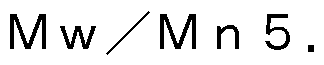 0) とプチルゴム (丨

巳11丁丫1_ 268」 、 1\/1\«約54万、 1\/1\«
 50の質量比で配合したものをトルエンに溶解 して、 固形分濃度 25質量%のゴム系粘着剤組成物を調製した。
[0123] <アクリル系粘着剤>
窒素導入管、 冷却管を備えた 4つロフラスコに、 2—エチルヘキシルアク リレート 95質量部、 アクリル酸 5質量部、 ベンゾイルパーオキサイ ド 0 . 1 5質量部および酢酸ェチル 200質量部を投入し、 十分に窒素置換した 後、 窒素気流下で撹拌しながら、 60°0で1 2時間反応して、 重量平均分子
〇 2020/175328 31 卩(:171? 2020 /006888
量 1 30万のアクリル系ポリマー溶液を得た。 上記アクリル系ポリマー溶液 の固形分 1 〇〇質量部に対して、 架橋剤として、 イソシアネート系架橋剤 ( 日本ポリウレタン (株) 製, コロネート!-) 2質量部配合し、 アクリル系粘 着剤組成物 (固形分濃度 32質量%) を調製した。
[0124] [実施例·!〜 3]
上記で調製したゴム系粘着剤組成物を商品名 「剥離フィルム 巳丁 _ 75 - 3〇八 1」 (フジコー社製) の剥離処理面に、 図 2のストライプ状のバタ —ンを、 表 1 に記載の密度となるように、 ディスペンサー (武蔵エンジニア リング株式会社製 3 II〇 1
 1 6 〇 を使って直線状の線幅で粘着剤部 分:非粘着剤部分を 2 : 1、 1 : 1 , 1 : 2の間隔でそれぞれ塗布し、 1 2 〇 で 3分間乾燥させて〇.
 の厚みの粘着剤層を形成し、 実施例 1 〜 3の電気絶縁材料を得た。
粘着剤層の表面 (粘着面) の保護には、 商品名 「ダイアホイル 1\/1[¾ 38 」 (三菱化学ポリエステルフィルム社製) の剥離処理面を用いた。
[0125] [実施例 4]
上記ゴム系粘着剤組成物を調製する際に、 中空粒子としてマツモトマイク ロスフェアー (松本油脂製薬株式会社製) をゴム系粘着剤組成物中、 9質量 %となるように添加して調製した中空粒子入りゴム系粘着剤組成物を、 商品 名 「剥離フィルム 巳丁一 75—
 八 1」 (フジコー社製) の剥離処理面 に、 乾燥後の粘着剤層の厚みが表 1 に記載の厚みとなるように全面に塗布し 、 1 20°◦で 3分間乾燥させて粘着剤層を形成し、 実施例 4の電気絶縁材料 を得た。
粘着剤層の表面 (粘着面) の保護には、 商品名 「ダイアホイル 1\/1[¾ 38 」 (三菱化学ポリエステルフィルム社製) の剥離処理面を用いた。
[0126] [実施例 5]
上記で調製したゴム系粘着剤組成物を、 基材としてのポリオレフィンフィ ルム (商品名 :ボラーラ XI - _1~1 #03001) (積水化学株式会社製 ) の片面側全面に、 乾燥後の粘着剤層の厚み及び密度が表 1 に記載の厚み及
〇 2020/175328 32 卩(:171? 2020 /006888
び密度となるように塗布し、 1 20°〇で 3分間乾燥させて粘着剤層を形成し 、 実施例 5の電気絶縁材料を得た。
粘着剤層の表面 (粘着面) の保護には、 商品名 「ダイアホイル 1\/1[¾ 38 」 (三菱化学ポリエステルフィルム社製) の剥離処理面を用いた。
[0127] [実施例 6〜 9]
上記で調製したゴム系粘着剤組成物を、 基材としてのポリオレフィンフィ ルム (商品名 :ボラーラ XI - _1~1 #03001) (積水化学株式会社製 ) の片面に、 図 2のストライプ状のバターンを、 乾燥後の粘着剤層の厚み及 び密度が表 1及び 2に記載の厚み及び密度となるように、 ディスペンサ _ ( 武蔵エンジニアリング株式会社製 3
 「) を使って、 直線状 の線幅で粘着剤部分:非粘着剤部分を 2 : 1、 1 : 1. 5、 1 : 2、 1 : 2 . 5の間隔でそれぞれ塗布し、 1 20°〇で 3分間乾燥させて粘着剤層を形成 し、 実施例 6〜 9の電気絶縁材料を得た。
粘着剤層の表面 (粘着面) の保護には、 商品名 「ダイアホイル 1\/1[¾ 38 」 (三菱化学ポリエステルフィルム社製) の剥離処理面を用いた。
[0128] [実施例 1 0]
上記ゴム系粘着剤組成物をアクリル系粘着剤に変更し、 図 2のストライプ 状のパターンを、 乾燥後の粘着剤層の厚み及び密度が、 表 2に記載の厚み及 び密度となるように塗布線幅を変更して塗布した以外は実施例 6と同様にし て実施例 1 〇の電気絶縁材料を得た。
[0129] [実施例 1 1 ]
基材を〇 #30 (東レ株式会社社製 商品名 : トレファン) に変更し た以外は実施例 6と同様にして実施例 1 1の電気絶縁材料を得た。
[0130] [実施例 1 2]
基材を 巳丁#25 (東レ株式会社製 商品名 : 3— 1 0) に変更した以 外は実施例 6と同様にして実施例 1 2の電気絶縁材料を得た。
[0131] [実施例 1 3]
ゴム系粘着剤組成物を実施例 4で用いた中空粒子入りのゴム系粘着剤組成
〇 2020/175328 33 卩(:171? 2020 /006888
物に変更し、 乾燥後の粘着剤層の厚みが表 2に記載の厚みとなるように片面 側全面に塗布した以外は実施例 5と同様にして実施例 1 3の電気絶縁材料を 得た。
[0132] [実施例 1 4]
上記で調製したゴム系粘着剤組成物を、 基材としてのポリオレフィンフィ ルム (商品名 :ボラーラ XI - _1~1 #03001) (積水化学株式会社製 ) の両面側全面に乾燥後の粘着剤層の厚みが表 3に記載の厚みとなるように 塗布し、 1 20°〇で 3分間乾燥させて粘着剤層を形成し、 実施例 1 4の電気 絶縁材料を得た。
粘着剤層の表面 (粘着面) の保護には、 商品名 「ダイアホイル 1\/1[¾ 38 」 (三菱化学ポリエステルフィルム社製) の剥離処理面を用いた。
[0133] [実施例 1 5〜 1 8]
上記で調製したゴム系粘着剤組成物を、 基材としてのポリオレフィンフィ ルム (商品名 :ボラーラ XI - _1~1 #03001) (積水化学株式会社製 ) の両面に、 図 2のストライプ状のパターンを、 乾燥後の粘着剤層の厚み及 び密度が表 3に記載の厚み及び密度となるように、 ディスペンサー (武蔵エ ンジニアリング株式会社製 3 II〇 I 0133 I 6 〇 を使って、 直線状の線幅 で粘着剤部分:非粘着剤部分を 1 : 2. 5、 1 : 1、 1 : 2、 1 : 1. 5の 間隔でそれぞれ塗布し、 1 20°〇で 3分間乾燥させて粘着剤層を形成し、 実 施例 1 5〜 1 8の電気絶縁材料を得た。
粘着剤層の表面 (粘着面) の保護には、 商品名 「ダイアホイル 1\/1[¾ 38 」 (三菱化学ポリエステルフィルム社製) の剥離処理面を用いた。
[0134] [実施例 1 9]
上記ゴム系粘着剤組成物をアクリル系粘着剤に変更し、 図 2のストライプ 状のパターンを、 乾燥後の粘着剤層の厚み及び密度が表 3に記載の厚み及び 密度となるように塗布した以外は実施例 1 5と同様にして実施例 1 9の電気 絶縁材料を得た。
[0135] [実施例 20]
〇 2020/175328 34 卩(:171? 2020 /006888
基材を〇 # 3 0 (東レ株式会社社製 商品名 : トレファン) に変更し 、 図 2のストライプ状のパターンを、 乾燥後の粘着剤層の厚み及び密度が表 3に記載の厚み及び密度となるように塗布した以外は実施例 1 5と同様にし て実施例 2 0の電気絶縁材料を得た。
[0136] [実施例 2 1 ]
基材を 巳丁# 2 5 (東レ株式会社製 商品名 : 3 - 1 0) に変更し、 図 2のストライプ状のパターンを、 乾燥後の粘着剤層の厚み及び密度が表 3に 記載の厚み及び密度となるように塗布した以外は実施例 1 5と同様にして実 施例 2 1の電気絶縁材料を得た。
[0137] [実施例 2 2 ]
基材を不織布 (大王製紙株式会社社製 商品名 :ポリエステルべーパー) に変更し、 図 2のストライプ状のパターンを、 乾燥後の粘着剤層の厚み及び 密度が表 4に記載の厚み及び密度となるように塗布した以外は実施例 1 5と 同様にして実施例 2 2の電気絶縁材料を得た。
[0138] [実施例 2 3 ]
基材を 丁 巳 (日東電工株式会社製 商品名 : !\1丁 ) に変更し、 乾燥 後の粘着剤層の厚みが表 4に記載の厚みとなるように塗布した以外は実施例 1 4と同様にして実施例 2 3の電気絶縁材料を得た。
[0139] [実施例 2 4 ]
ゴム系粘着剤組成物を実施例 4で用いた中空粒子入りのゴム系粘着剤組成 物に変更し、 乾燥後の粘着剤層の厚みが表 4に記載の厚みとなるように塗布 した以外は実施例 1 4と同様にして実施例 2 4の電気絶縁材料を得た。
[0140] [実施例 2 5 ]
上記で調製したゴム系粘着剤組成物を、 基材としてのポリオレフィンフィ ルム (商品名 :ボラーラ X I - _ 1~1 # 0 3 0 0 1) (積水化学株式会社製 ) の一方の面に、 図 2のストライプ状のバターンを、 乾燥後の粘着剤層の厚 み及び密度が表 4に記載の厚み及び密度となるように、 ディスペンサー (武 蔵エンジニアリング株式会社製 3 II〇 1: 01 8 3 ㊀ 「) を使って塗布し、 1
〇 2020/175328 35 卩(:171? 2020 /006888
20°〇で 3分間乾燥させて粘着剤層を形成した。 さらに、 基材のもう一方の 面に、 ゴム系粘着剤組成物を乾燥後の粘着剤層の厚み及び密度が表 4に記載 の厚み及び密度となるように全面に塗布し、 1 20°〇で 3分間乾燥させて粘 着剤層を形成し、 実施例 25の電気絶縁材料を得た。
粘着剤層の表面 (粘着面) の保護には、 商品名 「ダイアホイル 1\/1[¾ 38 」 (三菱化学ポリエステルフィルム社製) の剥離処理面を用いた。
[0141] [実施例 26]
上記で調製したゴム系粘着剤組成物を商品名 「剥離フィルム 巳丁 _ 75
— 3〇八 1」 (フジコー社製) の剥離処理面に、 表 5に記載の密度となるよ うに、 ディスペンサー (武蔵エンジニアリング株式会社製 3 〇 I 0133 1 ㊀ 〇 を使ってドッ ト状に粘着剤部分が〇 1. 〇 、 各ドッ ト間隔を〇.

みの粘着剤層を形成し、 実施例 26の電気絶縁材料を得た。
粘着剤層の表面 (粘着面) の保護には、 商品名 「ダイアホイル 1\/1[¾ 38 」 (三菱化学ポリエステルフィルム社製) の剥離処理面を用いた。
[0142] [実施例 27〜 28]
上記で調製したゴム系粘着剤組成物を商品名 「剥離フィルム 巳丁 _ 75
— 3〇八 1」 (フジコー社製) の剥離処理面に、 表 5に記載の密度となるよ うに、 ディスペンサーを使って直線状の線幅で粘着剤部分:非粘着剤部分を 2 : 1 になるように塗布し、 1 20°〇で 3分間乾燥させて〇.

みの粘着剤層を形成し、 実施例 27〜 28の電気絶縁材料を得た。
粘着剤層の表面 (粘着面) の保護には、 商品名 「ダイアホイル 1\/1[¾ 38 」 (三菱化学ポリエステルフィルム社製) の剥離処理面を用いた。
[0143] [比較例 1 ]
上記で調製したゴム系粘着剤組成物を、 基材としての〇 #30 (東レ 株式会社社製 商品名 : トレファン) の両面に、 乾燥後の粘着剤層の厚みが 表 4に記載の厚みとなるように全面に塗布し、 1 20°〇で 3分間乾燥させて 粘着剤層を形成し、 比較例 1の電気絶縁材料を得た。
〇 2020/175328 36 卩(:171? 2020 /006888
粘着剤層の表面 (粘着面) の保護には、 商品名 「ダイアホイル 1\/1 [¾ 3 8 」 (三菱化学ポリエステルフィルム社製) の剥離処理面を用いた。
[0144] [比較例 2 ]
基材を 巳丁# 2 5 (東レ株式会社製 商品名
 に変更し、 乾 燥後の粘着剤層の厚みが表 4に記載の厚みとなるように塗布した以外は比較 例 1 と同様にして比較例 2の電気絶縁材料を得た。
[0145] [比較例 3 ]
基材を不織布 (大王製紙株式会社社製 商品名 :ポリエステルべーパー) に変更し、 乾燥後の粘着剤層の厚みが表 4に記載の厚みとなるように塗布し た以外は比較例 1 と同様にして比較例 3の電気絶縁材料を得た。
[0146] [比較例 4〜 5 ]
ゴム系粘着剤組成物を、 図 2のストライプ状のパターンにて、 乾燥後の粘 着剤層の厚み及び密度が表 4に記載の厚み及び密度となるように直線状の線 幅で粘着剤部分:非粘着剤部分を 1 : 1、 の間隔でそれぞれ塗布した以外は 、 実施例 1 5と同様にして比較例 4〜 5の電気絶縁材料を得た。
[0147] [比較例 6 ]
ゴム系粘着剤組成物を、 上記ゴム系粘着剤組成物を調製する際に、 中空粒 子としてマツモトマイクロスフェアー (松本油脂製薬株式会社製) をゴム系 粘着剤組成物中、 1 2質量%となるように添加して調製した中空粒子入りゴ ム系粘着剤組成物に変更し、 乾燥後の粘着剤層の厚みが表 2に記載の厚みと なるように片面側全面に塗布した以外は実施例 5と同様にして比較例 6の電 気絶縁材料を得た。
[0148] [比較例 7 ]
上記で調製したゴム系粘着剤組成物を商品名 「剥離フィルム 巳丁 _ 7 5 - 3〇八 1」 (フジコー社製) の剥離処理面に、 全面に塗布し、 1 2 0 °〇で 3分間乾燥させて〇. 0 5
 の厚みの粘着剤層を形成し、 比較例 7の電気 絶縁材料を得た。
粘着剤層の表面 (粘着面) の保護には、 商品名 「ダイアホイル 1\/1 [¾ 3 8
龇鰹¾。」」洋 ¾」||到 (¾: ¾7辐 ^ ^ 81 > <^:^ _:11
〔§〔谢0_


〔 105—1


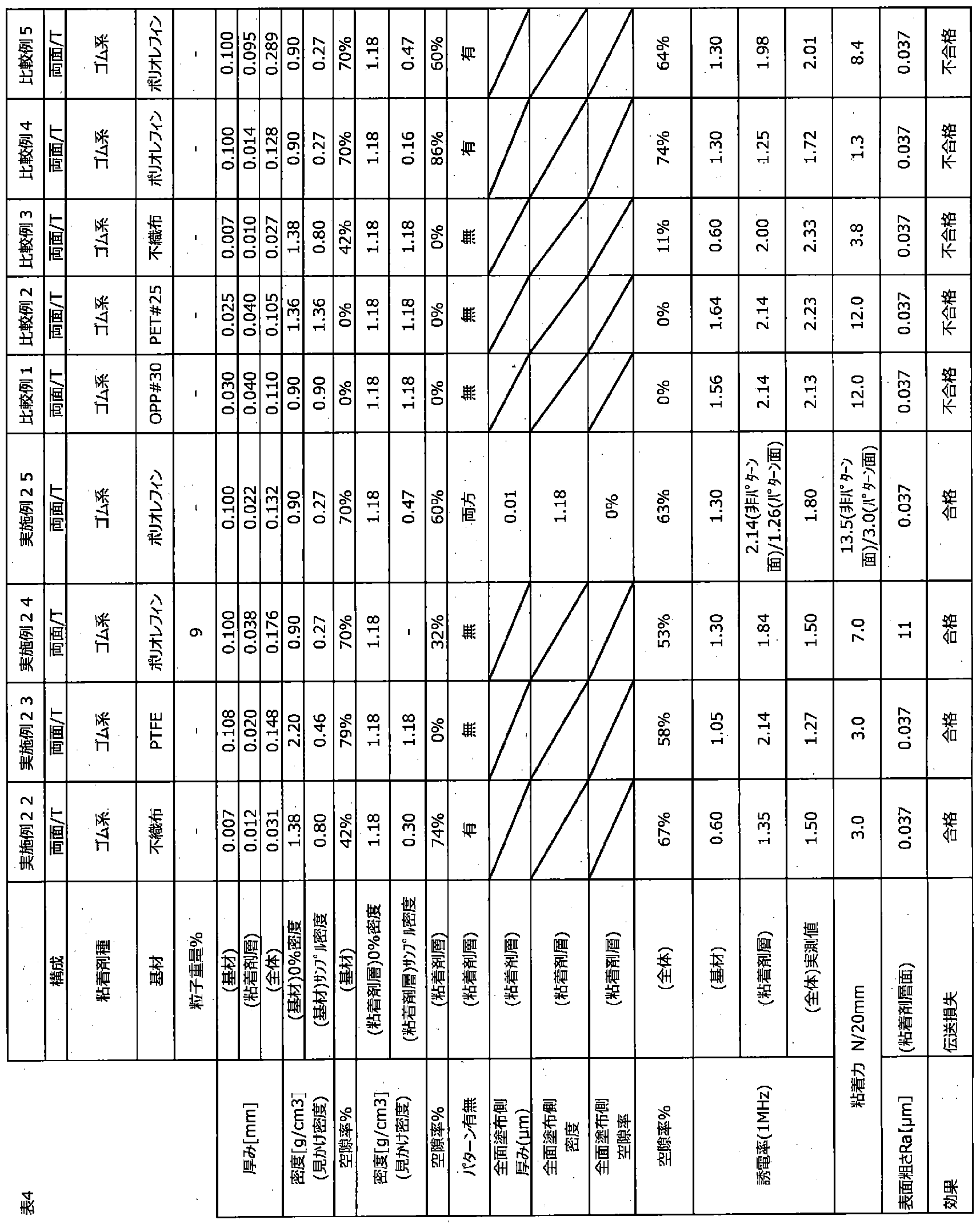
〇 2020/175328 41 卩(:171? 2020 /006888
[表 5]

[0155] 以上、 本発明の好ましい実施の形態について説明したが、 本発明は、 上述 した実施の形態に制限されるものではなく、 本発明の範囲を逸脱しない範囲 において、 上述した実施の形態に種々の変形及び置換を加えることができる なお、 本出願は、 201 9年2月 28日出願の日本特許出願 (特願 201 9-036325) に基づくものであり、 その内容は本出願の中に参照とし て援用される。
符号の説明
[0156] 1、 20、 30、 40 電気絶縁材料
〇 2020/175328 42 卩(:171? 2020 /006888
1 1 3、 1 1 2 1、 3 1、 4 1 基材
1 2 点状粘着剤
22 直線状粘着剤
32 波状粘着剤
42 格子状粘着剤
Claims
[請求項 1 ] 粘着剤層を備え、
 nにおける 1
8 0度ピール接着力が
 以上、 周波数
 における 比誘電率が 2以下、 空隙率が 3 0体積%以上である電気絶縁材料。
[請求項 2] 前記粘着剤層は、 周波数 1
 åにおける比誘電率が 2 . 7以下で ある請求項 1 に記載の電気絶縁材料。
[請求項 3] 前記粘着剤層は、 空隙率が〇〜 7 5体積%である請求項 1又は 2に 記載の電気絶縁材料。
[請求項 4] 更に、 基材を備える請求項 1〜 3のいずれか一項に記載の電気絶縁 材料。
[請求項 5] 前記基材は、 周波数 1
 åにおける比誘電率が 2 . 0以下である 請求項 4に記載の電気絶縁材料。
[請求項 6] 前記粘着剤層は、 ゴム系樹脂を含む請求項 1〜 5のいずれか一項に 記載の電気絶縁料。
[請求項 7] テープ状であり、 厚みが〇. 5
 以下である請求項 1〜 6のいず れか一項に記載の電気絶縁材料。
[請求項 8] 請求項 1〜 7のいずれか一項に記載の電気絶縁材料と、 剥離ライナ
_とを備える電気絶縁物品。
Priority Applications (2)
| Application Number | Priority Date | Filing Date | Title |
|---|---|---|---|
| CN202080010924.3A CN113366589A (zh) | 2019-02-28 | 2020-02-20 | 电绝缘材料和电绝缘物品 |
| KR1020217026340A KR20210131333A (ko) | 2019-02-28 | 2020-02-20 | 전기 절연 재료 및 전기 절연 물품 |
Applications Claiming Priority (2)
| Application Number | Priority Date | Filing Date | Title |
|---|---|---|---|
| JP2019036325 | 2019-02-28 | ||
| JP2019-036325 | 2019-02-28 |
Publications (1)
| Publication Number | Publication Date |
|---|---|
| WO2020175328A1 true WO2020175328A1 (ja) | 2020-09-03 |
Family
ID=72239135
Family Applications (1)
| Application Number | Title | Priority Date | Filing Date |
|---|---|---|---|
| PCT/JP2020/006888 Ceased WO2020175328A1 (ja) | 2019-02-28 | 2020-02-20 | 電気絶縁材料、及び電気絶縁物品 |
Country Status (5)
| Country | Link |
|---|---|
| JP (1) | JP2020145187A (ja) |
| KR (1) | KR20210131333A (ja) |
| CN (1) | CN113366589A (ja) |
| TW (1) | TW202039744A (ja) |
| WO (1) | WO2020175328A1 (ja) |
Cited By (2)
| Publication number | Priority date | Publication date | Assignee | Title |
|---|---|---|---|---|
| WO2022207460A1 (de) * | 2021-04-01 | 2022-10-06 | Tesa Se | Verwendung eines haftklebstreifens als abdeckung einer hochfrequenzstrahlungsquelle |
| WO2024135649A1 (ja) * | 2022-12-20 | 2024-06-27 | 積水化学工業株式会社 | 粘着シート、及び、粘着シートの製造方法 |
Families Citing this family (2)
| Publication number | Priority date | Publication date | Assignee | Title |
|---|---|---|---|---|
| JP7753843B2 (ja) * | 2021-12-03 | 2025-10-15 | 王子ホールディングス株式会社 | アンテナ基板用粘着シート及びアンテナ基板 |
| FR3132267A1 (fr) * | 2022-01-31 | 2023-08-04 | Autoliv Development Ab | Volant de véhicule avec un dispositif électrique |
Citations (2)
| Publication number | Priority date | Publication date | Assignee | Title |
|---|---|---|---|---|
| JP2015054867A (ja) * | 2013-09-10 | 2015-03-23 | 綜研化学株式会社 | 光学用粘着剤組成物、画像表示装置および入出力装置 |
| JP2017008189A (ja) * | 2015-06-22 | 2017-01-12 | 株式会社寺岡製作所 | 粘着テープ |
Family Cites Families (4)
| Publication number | Priority date | Publication date | Assignee | Title |
|---|---|---|---|---|
| JPH11288621A (ja) | 1998-04-03 | 1999-10-19 | Techno Onishi:Kk | 低誘電率絶縁材料および電気・電子機器 |
| JP5964951B2 (ja) * | 2012-07-30 | 2016-08-03 | 帝人株式会社 | 非水電解質電池用セパレータおよび非水電解質電池 |
| KR102347913B1 (ko) * | 2014-09-18 | 2022-01-06 | 미쯔비시 케미컬 주식회사 | 광가교성 투명 점착재, 투명 점착재 적층체 및 광학 장치 구성용 적층체 |
| KR101940543B1 (ko) * | 2014-12-24 | 2019-01-21 | 주식회사 엘지화학 | 아크릴계 점착 시트, 의료용 점착 테이프 및 제조방법 |
-
2020
- 2020-02-20 JP JP2020027381A patent/JP2020145187A/ja active Pending
- 2020-02-20 WO PCT/JP2020/006888 patent/WO2020175328A1/ja not_active Ceased
- 2020-02-20 CN CN202080010924.3A patent/CN113366589A/zh not_active Withdrawn
- 2020-02-20 KR KR1020217026340A patent/KR20210131333A/ko not_active Withdrawn
- 2020-02-25 TW TW109106008A patent/TW202039744A/zh unknown
Patent Citations (2)
| Publication number | Priority date | Publication date | Assignee | Title |
|---|---|---|---|---|
| JP2015054867A (ja) * | 2013-09-10 | 2015-03-23 | 綜研化学株式会社 | 光学用粘着剤組成物、画像表示装置および入出力装置 |
| JP2017008189A (ja) * | 2015-06-22 | 2017-01-12 | 株式会社寺岡製作所 | 粘着テープ |
Cited By (2)
| Publication number | Priority date | Publication date | Assignee | Title |
|---|---|---|---|---|
| WO2022207460A1 (de) * | 2021-04-01 | 2022-10-06 | Tesa Se | Verwendung eines haftklebstreifens als abdeckung einer hochfrequenzstrahlungsquelle |
| WO2024135649A1 (ja) * | 2022-12-20 | 2024-06-27 | 積水化学工業株式会社 | 粘着シート、及び、粘着シートの製造方法 |
Also Published As
| Publication number | Publication date |
|---|---|
| JP2020145187A (ja) | 2020-09-10 |
| TW202039744A (zh) | 2020-11-01 |
| KR20210131333A (ko) | 2021-11-02 |
| CN113366589A (zh) | 2021-09-07 |
Similar Documents
| Publication | Publication Date | Title |
|---|---|---|
| WO2020175328A1 (ja) | 電気絶縁材料、及び電気絶縁物品 | |
| EP2345708B1 (en) | Pressure-sensitive adhesive tape | |
| US20130244020A1 (en) | Bubble-containing thermally conductive resin composition layer, producing method thereof, and pressure-sensitive adhesive sheet using bubble-containing thermally conductive resin composition layer | |
| KR102732185B1 (ko) | 양면 점착 테이프 | |
| JP6653290B2 (ja) | 両面粘着シート及び携帯電子機器 | |
| JP2016108533A (ja) | 粘着シート | |
| JP7075936B2 (ja) | 粘着テープ用基材、粘着テープ及びその製造方法 | |
| CN101024757A (zh) | 双面压敏粘着带或片 | |
| JP7323360B2 (ja) | 両面粘着テープ | |
| JP6045929B2 (ja) | 難燃性熱伝導性粘着シート | |
| WO2009069486A1 (ja) | ガスバリア性物質偏在ポリマー層を有するガスバリア部材、及び該ガスバリア部材の製造方法 | |
| CN101831251A (zh) | 丙烯酸系粘合片 | |
| US20230022110A1 (en) | Adhesive tape and electronic device | |
| EP1533339A1 (en) | Resin composition for use in release film and release film produced therefrom | |
| TW201900741A (zh) | 衝擊吸收片及雙面黏著片 | |
| JP2015145478A (ja) | 熱伝導性両面粘着シート | |
| JP5060834B2 (ja) | 非相溶性物質偏在ポリマー層を有するポリマー部材、及び該ポリマー部材からなる表面凹凸テープ又はシート | |
| JP6317938B2 (ja) | 粘着シート | |
| JP2000006287A (ja) | 制振構造体 | |
| JP2023104865A (ja) | 発泡部材 | |
| JP6955947B2 (ja) | 積層体 | |
| CN102355993A (zh) | 聚合物部件的制造方法及聚合物部件 | |
| JP7221735B2 (ja) | ポリオレフィン系樹脂発泡体シート及びそれを用いた粘着テープ | |
| JP7128008B2 (ja) | 電子機器用シール材 | |
| WO2023139826A1 (ja) | 発泡部材 |
Legal Events
| Date | Code | Title | Description |
|---|---|---|---|
| 121 | Ep: the epo has been informed by wipo that ep was designated in this application |
Ref document number: 20763059 Country of ref document: EP Kind code of ref document: A1 |
|
| NENP | Non-entry into the national phase |
Ref country code: DE |
|
| 122 | Ep: pct application non-entry in european phase |
Ref document number: 20763059 Country of ref document: EP Kind code of ref document: A1 |