WO2020174618A1 - Dispositif de climatisation - Google Patents
Dispositif de climatisation Download PDFInfo
- Publication number
- WO2020174618A1 WO2020174618A1 PCT/JP2019/007628 JP2019007628W WO2020174618A1 WO 2020174618 A1 WO2020174618 A1 WO 2020174618A1 JP 2019007628 W JP2019007628 W JP 2019007628W WO 2020174618 A1 WO2020174618 A1 WO 2020174618A1
- Authority
- WO
- WIPO (PCT)
- Prior art keywords
- refrigerant
- heat
- heat exchanger
- temperature
- flow path
- Prior art date
Links
Images


Classifications
-
- F—MECHANICAL ENGINEERING; LIGHTING; HEATING; WEAPONS; BLASTING
- F24—HEATING; RANGES; VENTILATING
- F24F—AIR-CONDITIONING; AIR-HUMIDIFICATION; VENTILATION; USE OF AIR CURRENTS FOR SCREENING
- F24F11/00—Control or safety arrangements
- F24F11/70—Control systems characterised by their outputs; Constructional details thereof
- F24F11/80—Control systems characterised by their outputs; Constructional details thereof for controlling the temperature of the supplied air
- F24F11/86—Control systems characterised by their outputs; Constructional details thereof for controlling the temperature of the supplied air by controlling compressors within refrigeration or heat pump circuits
-
- F—MECHANICAL ENGINEERING; LIGHTING; HEATING; WEAPONS; BLASTING
- F25—REFRIGERATION OR COOLING; COMBINED HEATING AND REFRIGERATION SYSTEMS; HEAT PUMP SYSTEMS; MANUFACTURE OR STORAGE OF ICE; LIQUEFACTION SOLIDIFICATION OF GASES
- F25B—REFRIGERATION MACHINES, PLANTS OR SYSTEMS; COMBINED HEATING AND REFRIGERATION SYSTEMS; HEAT PUMP SYSTEMS
- F25B41/00—Fluid-circulation arrangements
- F25B41/20—Disposition of valves, e.g. of on-off valves or flow control valves
-
- F—MECHANICAL ENGINEERING; LIGHTING; HEATING; WEAPONS; BLASTING
- F25—REFRIGERATION OR COOLING; COMBINED HEATING AND REFRIGERATION SYSTEMS; HEAT PUMP SYSTEMS; MANUFACTURE OR STORAGE OF ICE; LIQUEFACTION SOLIDIFICATION OF GASES
- F25B—REFRIGERATION MACHINES, PLANTS OR SYSTEMS; COMBINED HEATING AND REFRIGERATION SYSTEMS; HEAT PUMP SYSTEMS
- F25B13/00—Compression machines, plants or systems, with reversible cycle
-
- F—MECHANICAL ENGINEERING; LIGHTING; HEATING; WEAPONS; BLASTING
- F25—REFRIGERATION OR COOLING; COMBINED HEATING AND REFRIGERATION SYSTEMS; HEAT PUMP SYSTEMS; MANUFACTURE OR STORAGE OF ICE; LIQUEFACTION SOLIDIFICATION OF GASES
- F25B—REFRIGERATION MACHINES, PLANTS OR SYSTEMS; COMBINED HEATING AND REFRIGERATION SYSTEMS; HEAT PUMP SYSTEMS
- F25B40/00—Subcoolers, desuperheaters or superheaters
- F25B40/02—Subcoolers
-
- F—MECHANICAL ENGINEERING; LIGHTING; HEATING; WEAPONS; BLASTING
- F25—REFRIGERATION OR COOLING; COMBINED HEATING AND REFRIGERATION SYSTEMS; HEAT PUMP SYSTEMS; MANUFACTURE OR STORAGE OF ICE; LIQUEFACTION SOLIDIFICATION OF GASES
- F25B—REFRIGERATION MACHINES, PLANTS OR SYSTEMS; COMBINED HEATING AND REFRIGERATION SYSTEMS; HEAT PUMP SYSTEMS
- F25B43/00—Arrangements for separating or purifying gases or liquids; Arrangements for vaporising the residuum of liquid refrigerant, e.g. by heat
- F25B43/006—Accumulators
-
- F—MECHANICAL ENGINEERING; LIGHTING; HEATING; WEAPONS; BLASTING
- F25—REFRIGERATION OR COOLING; COMBINED HEATING AND REFRIGERATION SYSTEMS; HEAT PUMP SYSTEMS; MANUFACTURE OR STORAGE OF ICE; LIQUEFACTION SOLIDIFICATION OF GASES
- F25B—REFRIGERATION MACHINES, PLANTS OR SYSTEMS; COMBINED HEATING AND REFRIGERATION SYSTEMS; HEAT PUMP SYSTEMS
- F25B49/00—Arrangement or mounting of control or safety devices
- F25B49/02—Arrangement or mounting of control or safety devices for compression type machines, plants or systems
-
- F—MECHANICAL ENGINEERING; LIGHTING; HEATING; WEAPONS; BLASTING
- F25—REFRIGERATION OR COOLING; COMBINED HEATING AND REFRIGERATION SYSTEMS; HEAT PUMP SYSTEMS; MANUFACTURE OR STORAGE OF ICE; LIQUEFACTION SOLIDIFICATION OF GASES
- F25B—REFRIGERATION MACHINES, PLANTS OR SYSTEMS; COMBINED HEATING AND REFRIGERATION SYSTEMS; HEAT PUMP SYSTEMS
- F25B2313/00—Compression machines, plants or systems with reversible cycle not otherwise provided for
- F25B2313/003—Indoor unit with water as a heat sink or heat source
-
- F—MECHANICAL ENGINEERING; LIGHTING; HEATING; WEAPONS; BLASTING
- F25—REFRIGERATION OR COOLING; COMBINED HEATING AND REFRIGERATION SYSTEMS; HEAT PUMP SYSTEMS; MANUFACTURE OR STORAGE OF ICE; LIQUEFACTION SOLIDIFICATION OF GASES
- F25B—REFRIGERATION MACHINES, PLANTS OR SYSTEMS; COMBINED HEATING AND REFRIGERATION SYSTEMS; HEAT PUMP SYSTEMS
- F25B2313/00—Compression machines, plants or systems with reversible cycle not otherwise provided for
- F25B2313/027—Compression machines, plants or systems with reversible cycle not otherwise provided for characterised by the reversing means
- F25B2313/02742—Compression machines, plants or systems with reversible cycle not otherwise provided for characterised by the reversing means using two four-way valves
-
- F—MECHANICAL ENGINEERING; LIGHTING; HEATING; WEAPONS; BLASTING
- F25—REFRIGERATION OR COOLING; COMBINED HEATING AND REFRIGERATION SYSTEMS; HEAT PUMP SYSTEMS; MANUFACTURE OR STORAGE OF ICE; LIQUEFACTION SOLIDIFICATION OF GASES
- F25B—REFRIGERATION MACHINES, PLANTS OR SYSTEMS; COMBINED HEATING AND REFRIGERATION SYSTEMS; HEAT PUMP SYSTEMS
- F25B2313/00—Compression machines, plants or systems with reversible cycle not otherwise provided for
- F25B2313/029—Control issues
- F25B2313/0294—Control issues related to the outdoor fan, e.g. controlling speed
-
- F—MECHANICAL ENGINEERING; LIGHTING; HEATING; WEAPONS; BLASTING
- F25—REFRIGERATION OR COOLING; COMBINED HEATING AND REFRIGERATION SYSTEMS; HEAT PUMP SYSTEMS; MANUFACTURE OR STORAGE OF ICE; LIQUEFACTION SOLIDIFICATION OF GASES
- F25B—REFRIGERATION MACHINES, PLANTS OR SYSTEMS; COMBINED HEATING AND REFRIGERATION SYSTEMS; HEAT PUMP SYSTEMS
- F25B2600/00—Control issues
- F25B2600/02—Compressor control
- F25B2600/021—Inverters therefor
-
- F—MECHANICAL ENGINEERING; LIGHTING; HEATING; WEAPONS; BLASTING
- F25—REFRIGERATION OR COOLING; COMBINED HEATING AND REFRIGERATION SYSTEMS; HEAT PUMP SYSTEMS; MANUFACTURE OR STORAGE OF ICE; LIQUEFACTION SOLIDIFICATION OF GASES
- F25B—REFRIGERATION MACHINES, PLANTS OR SYSTEMS; COMBINED HEATING AND REFRIGERATION SYSTEMS; HEAT PUMP SYSTEMS
- F25B2600/00—Control issues
- F25B2600/02—Compressor control
- F25B2600/025—Compressor control by controlling speed
- F25B2600/0251—Compressor control by controlling speed with on-off operation
-
- F—MECHANICAL ENGINEERING; LIGHTING; HEATING; WEAPONS; BLASTING
- F25—REFRIGERATION OR COOLING; COMBINED HEATING AND REFRIGERATION SYSTEMS; HEAT PUMP SYSTEMS; MANUFACTURE OR STORAGE OF ICE; LIQUEFACTION SOLIDIFICATION OF GASES
- F25B—REFRIGERATION MACHINES, PLANTS OR SYSTEMS; COMBINED HEATING AND REFRIGERATION SYSTEMS; HEAT PUMP SYSTEMS
- F25B2600/00—Control issues
- F25B2600/02—Compressor control
- F25B2600/025—Compressor control by controlling speed
- F25B2600/0253—Compressor control by controlling speed with variable speed
-
- F—MECHANICAL ENGINEERING; LIGHTING; HEATING; WEAPONS; BLASTING
- F25—REFRIGERATION OR COOLING; COMBINED HEATING AND REFRIGERATION SYSTEMS; HEAT PUMP SYSTEMS; MANUFACTURE OR STORAGE OF ICE; LIQUEFACTION SOLIDIFICATION OF GASES
- F25B—REFRIGERATION MACHINES, PLANTS OR SYSTEMS; COMBINED HEATING AND REFRIGERATION SYSTEMS; HEAT PUMP SYSTEMS
- F25B2600/00—Control issues
- F25B2600/11—Fan speed control
- F25B2600/111—Fan speed control of condenser fans
-
- F—MECHANICAL ENGINEERING; LIGHTING; HEATING; WEAPONS; BLASTING
- F25—REFRIGERATION OR COOLING; COMBINED HEATING AND REFRIGERATION SYSTEMS; HEAT PUMP SYSTEMS; MANUFACTURE OR STORAGE OF ICE; LIQUEFACTION SOLIDIFICATION OF GASES
- F25B—REFRIGERATION MACHINES, PLANTS OR SYSTEMS; COMBINED HEATING AND REFRIGERATION SYSTEMS; HEAT PUMP SYSTEMS
- F25B2600/00—Control issues
- F25B2600/11—Fan speed control
- F25B2600/112—Fan speed control of evaporator fans
-
- F—MECHANICAL ENGINEERING; LIGHTING; HEATING; WEAPONS; BLASTING
- F25—REFRIGERATION OR COOLING; COMBINED HEATING AND REFRIGERATION SYSTEMS; HEAT PUMP SYSTEMS; MANUFACTURE OR STORAGE OF ICE; LIQUEFACTION SOLIDIFICATION OF GASES
- F25B—REFRIGERATION MACHINES, PLANTS OR SYSTEMS; COMBINED HEATING AND REFRIGERATION SYSTEMS; HEAT PUMP SYSTEMS
- F25B2600/00—Control issues
- F25B2600/25—Control of valves
- F25B2600/2507—Flow-diverting valves
-
- F—MECHANICAL ENGINEERING; LIGHTING; HEATING; WEAPONS; BLASTING
- F25—REFRIGERATION OR COOLING; COMBINED HEATING AND REFRIGERATION SYSTEMS; HEAT PUMP SYSTEMS; MANUFACTURE OR STORAGE OF ICE; LIQUEFACTION SOLIDIFICATION OF GASES
- F25B—REFRIGERATION MACHINES, PLANTS OR SYSTEMS; COMBINED HEATING AND REFRIGERATION SYSTEMS; HEAT PUMP SYSTEMS
- F25B2600/00—Control issues
- F25B2600/25—Control of valves
- F25B2600/2513—Expansion valves
-
- F—MECHANICAL ENGINEERING; LIGHTING; HEATING; WEAPONS; BLASTING
- F25—REFRIGERATION OR COOLING; COMBINED HEATING AND REFRIGERATION SYSTEMS; HEAT PUMP SYSTEMS; MANUFACTURE OR STORAGE OF ICE; LIQUEFACTION SOLIDIFICATION OF GASES
- F25B—REFRIGERATION MACHINES, PLANTS OR SYSTEMS; COMBINED HEATING AND REFRIGERATION SYSTEMS; HEAT PUMP SYSTEMS
- F25B2700/00—Sensing or detecting of parameters; Sensors therefor
- F25B2700/21—Temperatures
- F25B2700/2106—Temperatures of fresh outdoor air
-
- F—MECHANICAL ENGINEERING; LIGHTING; HEATING; WEAPONS; BLASTING
- F25—REFRIGERATION OR COOLING; COMBINED HEATING AND REFRIGERATION SYSTEMS; HEAT PUMP SYSTEMS; MANUFACTURE OR STORAGE OF ICE; LIQUEFACTION SOLIDIFICATION OF GASES
- F25B—REFRIGERATION MACHINES, PLANTS OR SYSTEMS; COMBINED HEATING AND REFRIGERATION SYSTEMS; HEAT PUMP SYSTEMS
- F25B2700/00—Sensing or detecting of parameters; Sensors therefor
- F25B2700/21—Temperatures
- F25B2700/2115—Temperatures of a compressor or the drive means therefor
- F25B2700/21151—Temperatures of a compressor or the drive means therefor at the suction side of the compressor
-
- F—MECHANICAL ENGINEERING; LIGHTING; HEATING; WEAPONS; BLASTING
- F25—REFRIGERATION OR COOLING; COMBINED HEATING AND REFRIGERATION SYSTEMS; HEAT PUMP SYSTEMS; MANUFACTURE OR STORAGE OF ICE; LIQUEFACTION SOLIDIFICATION OF GASES
- F25B—REFRIGERATION MACHINES, PLANTS OR SYSTEMS; COMBINED HEATING AND REFRIGERATION SYSTEMS; HEAT PUMP SYSTEMS
- F25B2700/00—Sensing or detecting of parameters; Sensors therefor
- F25B2700/21—Temperatures
- F25B2700/2115—Temperatures of a compressor or the drive means therefor
- F25B2700/21152—Temperatures of a compressor or the drive means therefor at the discharge side of the compressor
-
- F—MECHANICAL ENGINEERING; LIGHTING; HEATING; WEAPONS; BLASTING
- F25—REFRIGERATION OR COOLING; COMBINED HEATING AND REFRIGERATION SYSTEMS; HEAT PUMP SYSTEMS; MANUFACTURE OR STORAGE OF ICE; LIQUEFACTION SOLIDIFICATION OF GASES
- F25B—REFRIGERATION MACHINES, PLANTS OR SYSTEMS; COMBINED HEATING AND REFRIGERATION SYSTEMS; HEAT PUMP SYSTEMS
- F25B2700/00—Sensing or detecting of parameters; Sensors therefor
- F25B2700/21—Temperatures
- F25B2700/2116—Temperatures of a condenser
- F25B2700/21162—Temperatures of a condenser of the refrigerant at the inlet of the condenser
-
- F—MECHANICAL ENGINEERING; LIGHTING; HEATING; WEAPONS; BLASTING
- F25—REFRIGERATION OR COOLING; COMBINED HEATING AND REFRIGERATION SYSTEMS; HEAT PUMP SYSTEMS; MANUFACTURE OR STORAGE OF ICE; LIQUEFACTION SOLIDIFICATION OF GASES
- F25B—REFRIGERATION MACHINES, PLANTS OR SYSTEMS; COMBINED HEATING AND REFRIGERATION SYSTEMS; HEAT PUMP SYSTEMS
- F25B2700/00—Sensing or detecting of parameters; Sensors therefor
- F25B2700/21—Temperatures
- F25B2700/2116—Temperatures of a condenser
- F25B2700/21163—Temperatures of a condenser of the refrigerant at the outlet of the condenser
-
- F—MECHANICAL ENGINEERING; LIGHTING; HEATING; WEAPONS; BLASTING
- F25—REFRIGERATION OR COOLING; COMBINED HEATING AND REFRIGERATION SYSTEMS; HEAT PUMP SYSTEMS; MANUFACTURE OR STORAGE OF ICE; LIQUEFACTION SOLIDIFICATION OF GASES
- F25B—REFRIGERATION MACHINES, PLANTS OR SYSTEMS; COMBINED HEATING AND REFRIGERATION SYSTEMS; HEAT PUMP SYSTEMS
- F25B2700/00—Sensing or detecting of parameters; Sensors therefor
- F25B2700/21—Temperatures
- F25B2700/2117—Temperatures of an evaporator
- F25B2700/21174—Temperatures of an evaporator of the refrigerant at the inlet of the evaporator
-
- F—MECHANICAL ENGINEERING; LIGHTING; HEATING; WEAPONS; BLASTING
- F25—REFRIGERATION OR COOLING; COMBINED HEATING AND REFRIGERATION SYSTEMS; HEAT PUMP SYSTEMS; MANUFACTURE OR STORAGE OF ICE; LIQUEFACTION SOLIDIFICATION OF GASES
- F25B—REFRIGERATION MACHINES, PLANTS OR SYSTEMS; COMBINED HEATING AND REFRIGERATION SYSTEMS; HEAT PUMP SYSTEMS
- F25B2700/00—Sensing or detecting of parameters; Sensors therefor
- F25B2700/21—Temperatures
- F25B2700/2117—Temperatures of an evaporator
- F25B2700/21175—Temperatures of an evaporator of the refrigerant at the outlet of the evaporator
-
- Y—GENERAL TAGGING OF NEW TECHNOLOGICAL DEVELOPMENTS; GENERAL TAGGING OF CROSS-SECTIONAL TECHNOLOGIES SPANNING OVER SEVERAL SECTIONS OF THE IPC; TECHNICAL SUBJECTS COVERED BY FORMER USPC CROSS-REFERENCE ART COLLECTIONS [XRACs] AND DIGESTS
- Y02—TECHNOLOGIES OR APPLICATIONS FOR MITIGATION OR ADAPTATION AGAINST CLIMATE CHANGE
- Y02B—CLIMATE CHANGE MITIGATION TECHNOLOGIES RELATED TO BUILDINGS, e.g. HOUSING, HOUSE APPLIANCES OR RELATED END-USER APPLICATIONS
- Y02B30/00—Energy efficient heating, ventilation or air conditioning [HVAC]
- Y02B30/70—Efficient control or regulation technologies, e.g. for control of refrigerant flow, motor or heating
Definitions
- This invention relates to an air conditioner. In particular, it relates to an improvement in the structure of the refrigerant circulation circuit.
- an air conditioner that has a heat exchanger, etc., to form a refrigerant circulation circuit, circulates the refrigerant, performs heating operation and cooling operation, and performs air conditioning in the room that is the target space.
- the flow direction of the refrigerant passing through the heat exchanger during the heating operation and the cooling operation changes from the leeward side of the indoor air, which is a heat-utilizing fluid, to the upwind side (hereinafter referred to as counterflow).
- An air conditioner having a refrigerant circulation circuit is known (see, for example, Patent Document 1).
- the heat exchange efficiency in the heat exchanger can be increased because the refrigerant flow direction is a counter flow that faces the heat-utilizing fluid.
- the air conditioner described in Patent Document 1 includes an indoor heat exchanger, an outdoor heat exchanger, a six-way valve, a compressor, and a throttle device, and the refrigerant flow direction in the indoor heat exchanger during both heating operation and cooling operation.
- the refrigerant circulation circuit is configured so that the counter flows.
- the refrigerant flow direction is a counter flow in the use side heat exchanger.
- the pipe becomes a thick pipe in order to reduce the pressure loss during the cooling operation.
- the liquid refrigerant which is a liquid refrigerant
- the amount of refrigerant used increases.
- the performance may deteriorate.
- an object of the present invention is to provide an air conditioner capable of efficiently performing heat exchange and the like regardless of operation such as heating operation and cooling operation.
- An air conditioner according to the present invention, a heat source unit for generating hot heat or cold heat and carrying it to a refrigerant, a heat utilization unit for exchanging heat or cold heat carried by the refrigerant from the heat source unit to a heat load, and a heat source.
- the unit and the heat utilization unit are connected to each other, and the outgoing pipe in which the refrigerant flows from the heat source unit side to the heat utilization unit side, and the heat source unit and the heat utilization unit are respectively connected in parallel, and the heat utilization unit side is connected to the heat source.
- a return pipe having a plurality of pipes through which the refrigerant flows on the unit side, an opening/closing device installed in at least one of the return pipes to control the amount of the refrigerant passing through the return pipe, and the opening/closing device is opened during the cooling operation to provide heating.
- a control device that controls to close the switchgear during operation.
- the forward pipe through which the refrigerant flows from the heat source unit side to the utilization unit side and the return pipe through which the refrigerant flows from the utilization unit side to the heat source unit side are provided.
- the direction in which the refrigerant flows in the utilization unit is made constant, and the heat exchange with the refrigerant in the utilization unit is made to be a counterflow, so that the efficiency in the utilization unit can be improved.
- the return pipe has a plurality of pipes, and the switchgear is installed in at least one pipe. Then, the control device controls to close the opening/closing device, so that the flow passage area can be reduced in the entire return pipe. Therefore, the amount of refrigerant used can be reduced by closing the switchgear during heating operation.
- Embodiment 2 of this invention It is a figure explaining an example of the flow of the refrigerant at the time of cooling only operation of the air-conditioning apparatus in Embodiment 2 of this invention. It is a figure explaining an example of temperature distribution in intermediate heat exchanger 21a and intermediate heat exchanger 21b at the time of cooling operation of the air harmony device in Embodiment 2 of this invention. It is a figure explaining an example of the flow of the refrigerant etc. at the time of heating only operation of the air conditioning apparatus in Embodiment 2 of this invention. It is a figure explaining an example of temperature distribution in intermediate heat exchanger 21a and intermediate heat exchanger 21b at the time of all heating operation of the air harmony device in Embodiment 2 of this invention.
- FIG. 1 is a diagram schematically illustrating an example of the configuration of a circuit and the like in the air-conditioning apparatus according to Embodiment 1 of the present invention.
- the air conditioning apparatus 100 of the example of this embodiment performs heat exchange between the outdoor unit 1 and a medium that carries a heat different from the refrigerant and the refrigerant (hereinafter referred to as a heat medium) to relay the heat transfer.
- the repeater 2 and a plurality of indoor units 3 that are devices are provided as separate units.
- the refrigerant circulation circuit formed by connecting the outdoor unit 1, the relay 2, the forward pipe 4a, the return pipe 4b, and the return pipe 4c, and the relay 2 and the indoor unit 3 are connected by the heat medium pipe 5. It has a heat medium circulation circuit formed by the above.
- FIG. 1 shows an example in which two indoor units 3a and 3b are connected to the relay device 2, but the number of indoor units 3 may be two or more.
- a non-azeotropic mixed refrigerant is used as the refrigerant.
- the non-azeotropic mixed refrigerant is a refrigerant whose composition changes when evaporated and condensed, among refrigerants mixed with a plurality of refrigerants.
- the gas-liquid two-phase state does not reach a constant temperature even under the same pressure due to the change in composition. Therefore, in the heat exchanger, for example, the condensation end temperature (boiling point) becomes lower than the condensation start temperature (dew point).
- the temperature change width between the dew point and the boiling point is a temperature gradient.
- a simple substance refrigerant, an azeotropic mixed refrigerant, a pseudo-azeotropic mixed refrigerant, or the like can be used.
- the outdoor unit 1 is, for example, installed outside a room that is an air conditioning target space, and serves as a heat source unit that exhausts or supplies heat related to air conditioning to the outside.
- the outdoor unit 1 includes, for example, the compressor 11, the first flow path switching device 12, the heat source side heat exchanger 13, the second flow path switching device 14, the first expansion device 15, the accumulator 19, and the bypass circuit 40.
- the second expansion device 41 and the inter-refrigerant heat exchanger 42 are mounted, and these devices are connected by piping.
- the outdoor unit 1 is equipped with an outdoor fan 131 that is a blower that blows air to the heat source side heat exchanger 13.
- the compressor 11 draws in the refrigerant, compresses it, discharges it in a high temperature and high pressure state.
- the compressor 11 of the first embodiment is composed of, for example, an inverter compressor whose capacity can be controlled.
- a compressor having a low pressure shell structure and a high pressure shell structure can be used as the compressor 11 of the first embodiment.
- the low-pressure shell structure is a structure in which a compression chamber is provided in a closed container, and the inside of the closed container has a low-pressure refrigerant pressure atmosphere, and the low-pressure refrigerant in the closed container is sucked into the compression chamber to be compressed.
- the high-pressure shell structure creates a high-pressure refrigerant pressure atmosphere in the closed container, sucks the low-pressure refrigerant in the pipe connected to the compressor suction portion into the compression chamber, compresses it, and discharges it through the closed container. It is a structure.
- the first flow path switching device 12 is composed of, for example, a four-way valve. It is a device that switches the refrigerant flow path in the cooling operation and the refrigerant flow path in the heating operation to switch the heat exchanger acting as a condenser or a gas cooler.
- the first flow path switching device 12 is connected to the discharge side of the compressor 11, the heat source side heat exchanger 13, the first expansion device 15 and the outward pipe 4a. Then, in the first flow path switching device 12, during the cooling operation, the discharge side of the compressor 11 and the heat source side heat exchanger 13 communicate with each other, and the first expansion device 15 and the outgoing pipe 4a communicate with each other.
- the flow path of the refrigerant circulation circuit is switched to the cooling flow path.
- the heat source side heat exchanger 13 acts as a condenser or a gas cooler.
- the discharge side of the compressor 11 communicates with the forward pipe 4a, and the heat source side heat exchanger 13 communicates with the first expansion device 15.
- the flow path of the refrigerant circulation circuit is switched to the heating flow path.
- the intermediate heat exchanger 21a acts as a condenser or a gas cooler.
- the heat source side heat exchanger 13 exchanges heat between the outdoor air and the refrigerant.
- the heat source side heat exchanger 13 functions as a condenser or a gas cooler during the cooling operation, and functions as an evaporator during the heating operation.
- the outdoor fan 131 supplies outdoor air to the heat source side heat exchanger 13.
- the outdoor air becomes a heat source fluid that is a target of heat exchange with the refrigerant in the heat source side heat exchanger 13.
- the heat source fluid is not limited to this, and water or the like may be used.
- the second flow path switching device 14 is composed of, for example, a four-way valve or the like. It is a device that switches between the refrigerant flow path in the cooling operation and the refrigerant flow path in the heating operation to switch the heat exchanger that functions as an evaporator.
- the second flow path switching device 14 is connected to the suction side of the compressor 11, the heat source side heat exchanger 13, the first expansion device 15, the return pipe 4b, and the return pipe 4c. In the second flow path switching device 14, during the cooling operation, the suction side of the compressor 11 communicates with the return pipe 4b and the return pipe 4c, and the heat source side heat exchanger 13 and the first expansion device 15 are connected.
- the flow path of the refrigerant circulation circuit is switched to the cooling flow path so as to communicate with each other.
- the intermediate heat exchanger 21a acts as an evaporator.
- the second flow path switching device 14 during the heating operation, the suction side of the compressor 11 and the heat source side heat exchanger 13 communicate with each other, and the first expansion device 15 and the return pipe 4b and the return pipe 4c are connected.
- the flow path of the refrigerant circulation circuit is switched to the heating flow path so as to communicate with each other.
- the heat source side heat exchanger 13 acts as an evaporator.
- the second flow path switching device 14 is configured by a four-way valve or the like, but may be configured by combining two-way valves, for example.
- the air-conditioning apparatus 100 of Embodiment 1 has a forward pipe 4a, a return pipe 4b, and a return pipe 4c as connection pipes that connect the outdoor unit 1 and the relay unit 2.
- the forward pipe 4a has one end connected to the first flow path switching device 12 and the other end connected to the refrigerant inlet side of the intermediate heat exchanger 21a.
- One end of the return pipe 4b and the return pipe 4c is connected to the second flow path switching device 14, and the other end is connected to the refrigerant outlet side pipe of the intermediate heat exchanger 21a.
- the return pipe 4b and the return pipe 4c are connected in parallel between the outdoor unit 1 and the relay unit 2.
- the outward pipe 4a functions as a refrigerant flow path in which a low-pressure two-phase refrigerant flows during the cooling operation and a high-pressure gas refrigerant flows during the heating operation. Further, the refrigerant flowing through the outward pipe 4a flows from the outdoor unit 1 toward the relay unit 2 regardless of the operating state.
- the return pipe 4b functions as a refrigerant flow path in which the low-pressure two-phase refrigerant or the gas refrigerant flows during the cooling operation and the high-pressure liquid refrigerant flows during the heating operation.
- the return pipe 4b may be a pipe having a larger diameter than the return pipe 4c.
- the return pipe 4c functions as a refrigerant flow path in which the low-pressure two-phase refrigerant or the gas refrigerant flows during the cooling operation and the high-pressure liquid refrigerant flows during the heating operation, similarly to the return piping 4b.
- the return pipe 4c may have a larger diameter than the return pipe 4b. Further, the return pipe 4b and the return pipe 4c may have the same size.
- the refrigerant flowing through the return pipe 4b and the return pipe 4c flows from the relay device 2 toward the outdoor unit 1 regardless of the operating state.
- the first expansion device 15 is a device that functions as a pressure reducing valve or an expansion valve that decompresses and expands the refrigerant.
- the first expansion device 15 may be configured to have a controllable opening such as an electronic expansion valve.
- the first expansion device 15 is arranged in the pipe between the first flow path switching device 12 and the second flow path switching device 14.
- the accumulator 19 is provided in the suction section on the suction side of the compressor 11.
- the accumulator 19 stores the excess refrigerant in the refrigerant circulation circuit. For example, the amount of refrigerant required for air conditioning differs between the heating operation and the cooling operation. Therefore, the accumulator 19 stores the surplus refrigerant generated due to the difference in operation.
- the accumulator 19 stores the excess refrigerant that is transiently generated when the operation changes.
- the excess refrigerant is stored by the accumulator 19, but the present invention is not limited to this.
- the bypass circuit 40 is a pipe that partially bypasses the high-temperature and high-pressure refrigerant and causes it to flow into the suction section of the compressor 11.
- the bypass circuit 40 has one end connected to the pipe between the second flow path switching device 14 and the first expansion device 15, and the other end between the compressor 11 and the second flow path switching device 14. It is connected to the pipe.
- the bypass circuit 40 is provided with a second diaphragm device 41.
- the second expansion device 41 is a device that functions as a pressure reducing valve or an expansion valve that decompresses and expands the refrigerant.
- the second expansion device 41 may be configured to have a controllable opening such as an electronic expansion valve.
- the inter-refrigerant heat exchanger 42 is configured by, for example, a double tube heat exchanger or the like.
- the inter-refrigerant heat exchanger 42 is a medium-temperature and high-pressure refrigerant flowing between the second flow path switching device 14 and the first expansion device 15, and a low temperature flowing in the bypass circuit 40 flowing out of the second expansion device 41. And heat exchange with the low-pressure refrigerant to supercool the medium-temperature and high-pressure refrigerant.
- the outdoor unit 1 also has a high pressure detection sensor 73, a discharge temperature sensor 71, an intake temperature sensor 72, a low pressure detection sensor 74, a refrigerant heat exchanger outlet temperature sensor 76, and an outside air temperature sensor 75.
- the high pressure detection sensor 73 is a sensor that detects a high pressure which is the pressure of the refrigerant on the discharge side of the compressor 11.
- the discharge temperature sensor 71 is a sensor that detects the temperatures of the high-temperature and high-pressure refrigerant discharged from the compressor 11.
- the suction temperature sensor 72 is a sensor that detects the temperature of the low-temperature and low-pressure refrigerant sucked into the compressor 11.
- the low pressure detection sensor 74 is a sensor that detects a low pressure, which is the pressure of the refrigerant on the suction side of the compressor 11.
- the inter-refrigerant heat exchanger outlet temperature sensor 76 is a sensor that detects the temperature of the refrigerant that has undergone heat exchange in the inter-refrigerant heat exchanger 42.
- the outside air temperature sensor 75 is a sensor that is provided in the air suction portion of the heat source side heat exchanger 13 and detects the temperature around the outdoor unit 1 as the outside air temperature.
- the repeater 2 becomes a part of the heat utilization unit and performs heat exchange between the refrigerant and the heat medium.
- the repeater 2 has an intermediate heat exchanger 21a, a pump 22a, a heat medium feed pipe 61a, and a heat medium return pipe 62a.
- a pump 22a For example, in a building, it is installed in a non-air-conditioned space different from the air-conditioned space in which the indoor unit 3 is installed.
- the intermediate heat exchanger 21a has a heat transfer part that allows the refrigerant to pass through and a heat transfer part that allows the heat medium to pass through, and causes heat exchange between the medium by the refrigerant and the heat medium.
- the intermediate heat exchanger 21a functions as a condenser in the heating operation, and causes the refrigerant to radiate heat to heat the heat medium.
- the intermediate heat exchanger 21a functions as an evaporator in the cooling operation, and causes the refrigerant to absorb heat to cool the heat medium.
- the pump 22a serving as the first pump is a heat medium delivery device that pressurizes the heat medium and circulates the heat medium circulation circuit.
- the pump 22a can change the discharge flow rate, which is the flow rate for sending the heat medium, by changing the rotation speed of a built-in motor (not shown) within a certain range.
- the pump 22a is installed in the heat medium return pipe 62a that connects the intermediate heat exchanger 21a and the heat medium flow rate adjusting device 32a. Therefore, the heat medium sent out by the pump 22a flows into the intermediate heat exchanger 21a.
- the opening/closing device 52 is composed of, for example, a two-way valve, and opens/closes the return pipe 4c.
- the switchgear 52 is provided in the return pipe 4c on the outlet side of the intermediate heat exchanger 21a, and is housed in the repeater 2.
- the check valve 29 prevents the refrigerant passing through the return pipe 4b from flowing in the reverse direction to the return pipe 4c when the opening/closing device 52 is closed.
- the repeater 2 has a refrigerant temperature sensor 81, a refrigerant temperature sensor 83, a heat medium temperature sensor 24a, and a heat medium temperature sensor 25b.
- the refrigerant temperature sensor 81 is a sensor that detects the temperature of the refrigerant on the inlet side of the intermediate heat exchanger 21a.
- the refrigerant temperature sensor 83 is a sensor that detects the temperature of the refrigerant on the outlet side of the intermediate heat exchanger 21a.
- the heat medium temperature sensor 24a is a sensor that detects the temperature of the heat medium on the inlet side of the intermediate heat exchanger 21a.
- the heat medium temperature sensor 25a is a sensor that detects the temperature of the heat medium on the outlet side of the intermediate heat exchanger 21a.
- the indoor unit 3a and the indoor unit 3b are installed, for example, inside a room which is a target space, and supply conditioned air to the room.
- the indoor unit 3a and the indoor unit 3b become a part of heat utilization unit.
- the indoor unit 3a and the indoor unit 3b have a use side heat exchanger 31a, a use side heat exchanger 31b, a heat medium flow rate adjusting device 32a, and a heat medium flow rate adjusting device 32b, respectively, as devices of the heat medium circulation circuit.
- the user-side heat exchanger 31a and the user-side heat exchanger 31b are connected to the device on the repeater 2 side via the heat medium pipe 5.
- the use-side heat exchanger 31a and the use-side heat exchanger 31b perform heat exchange between the indoor air, which is a heat load, and the heat medium, thereby heating the heated air to be supplied to the indoor space or cooling the air for cooling. Generate air. Indoor air is blown from the indoor fan 311a and the indoor fan 311b to the usage-side heat exchanger 31a and the usage-side heat exchanger 31b, respectively.
- the heat medium flow rate adjusting device 32a and the heat medium flow rate adjusting device 32b are configured by a two-way valve or the like capable of controlling the opening area.
- the heat medium flow rate adjusting device 32a and the heat medium flow rate adjusting device 32b are devices that adjust the flow rate of the heat medium flowing through the use side heat exchanger 31a and the use side heat exchanger 31b, respectively.
- One of the heat medium flow rate adjusting device 32a and the heat medium flow rate adjusting device 32b is connected to the use side heat exchanger 31a and the use side heat exchanger 31b respectively, and the other is connected to the heat medium pipe 5 for use. It is provided on the outlet side of the heat medium flow passage of each of the side heat exchanger 31a and the use side heat exchanger 31b.
- the heat medium flow rate adjusting device 32a and the heat medium flow rate adjusting device 32b may be installed on the inlet side of the heat medium flow paths of the use side heat exchanger 31a and the use side heat exchanger 31b.
- the indoor unit 3a and the indoor unit 3b have an inlet temperature sensor 34a, an inlet temperature sensor 34b, an outlet temperature sensor 35a, and an outlet temperature sensor 35b, respectively.
- the inlet side temperature sensor 34a and the inlet side temperature sensor 34b are configured by, for example, a thermistor.
- the inlet side temperature sensor 34a and the inlet side temperature sensor 34b are sensors that detect the temperature of the heat medium flowing into the use side heat exchanger 31a and the use side heat exchanger 31b.
- the inlet-side temperature sensor 34a and the inlet-side temperature sensor 34b are provided in the pipes on the inlet side of the heat medium in the use-side heat exchanger 31a and the use-side heat exchanger 31b.
- the outlet-side temperature sensor 35a and the outlet-side temperature sensor 35b are composed of, for example, a thermistor.
- the outlet-side temperature sensor 35a and the outlet-side temperature sensor 35b are sensors that detect the temperature of the heat medium flowing out from the use-side heat exchanger 31a and the use-side heat exchanger 31b.
- the outlet side temperature sensor 35a and the outlet side temperature sensor 35b are provided on the outlet side of the heat medium in the use side heat exchanger 31a and the use side heat exchanger 31b.
- the control device 50 is a device that controls the entire air conditioning apparatus 100.
- the control device 50 is configured to include, for example, an analog circuit, a digital circuit, a CPU, or a combination of two or more of these.
- the control device 50 controls various devices and equipment based on, for example, physical quantity data detected by the various sensors described above and an instruction from an input device such as a remote controller, and executes each operation mode described later.
- the control device 50 controls the drive frequency of the compressor 11 in the outdoor unit 1, the rotation speed (including ON or OFF) of the outdoor fan 131, the first flow path switching device 12 and the second flow path switching device 14. And the opening degree of the first diaphragm device 15 and the second diaphragm device 41 are controlled.
- control device 50 controls the drive frequency of the pump 22a in the repeater 2 and the like. Further, the control device 50 controls the opening degree of the heat medium flow rate adjusting device 32a and the heat medium flow rate adjusting device 32b in the indoor unit 3a and the indoor unit 3b.
- FIG. 1 illustrates a case where the control device 50 is provided in the outdoor unit 1, but the present invention is not limited to this.
- the control device 50 may be provided in each of the outdoor unit 1, the relay unit 2, the indoor unit 3a, and the indoor unit 3b.
- the control device 50 may be provided in at least one of the indoor unit 3a and the indoor unit 3b.
- the air conditioning apparatus 100 can execute the cooling operation or the heating operation based on the instructions from the indoor unit 3a and the indoor unit 3b.
- the operation of the air conditioner 100 in each operation mode will be described together with the flow of the refrigerant and the state of the refrigerant.
- FIG. 2 is a diagram illustrating an example of the flow of the refrigerant during the cooling operation of the air-conditioning apparatus according to Embodiment 1 of the present invention.
- the cooling operation in the cooling operation mode in which the indoor unit 3a and the indoor unit 3b are performing cooling will be described.
- the flow direction of the refrigerant is shown by a solid arrow, and the flow direction of the heat medium is shown by a broken arrow.
- the compressor 11 draws in low-temperature and low-pressure gas refrigerant, compresses it, and discharges high-temperature and high-pressure gas refrigerant.
- the high temperature and high pressure gas refrigerant discharged from the compressor 11 flows into the heat source side heat exchanger 13 via the first flow path switching device 12.
- the heat source side heat exchanger 13 exchanges heat between the outdoor air supplied from the outdoor fan 131 and the high-temperature and high-pressure gas refrigerant.
- the high-temperature and high-pressure gas refrigerant is cooled by heat exchange to become a medium-temperature and high-pressure liquid refrigerant.
- the medium-temperature and high-pressure liquid refrigerant cooled in the heat source side heat exchanger 13 flows into the inter-refrigerant heat exchanger 42 via the second flow path switching device 14.
- the inter-refrigerant heat exchanger 42 heats the low-temperature and low-pressure two-phase refrigerant flowing in the bypass circuit 40 and the medium-temperature and high-pressure liquid refrigerant flowing between the second flow path switching device 14 and the first expansion device 15. Exchange.
- the medium-temperature and high-pressure liquid refrigerant is cooled by heat exchange to become a low-temperature and high-pressure liquid refrigerant.
- the low-temperature and high-pressure liquid refrigerant cooled by the inter-refrigerant heat exchanger 42 flows into the first expansion device 15.
- the first expansion device 15 reduces the pressure of the low-temperature and high-pressure liquid refrigerant.
- the low-temperature and low-pressure two-phase refrigerant decompressed by the first expansion device 15 flows into the intermediate heat exchanger 21a via the first flow path switching device 12 and the outward pipe 4a.
- the intermediate heat exchanger 21a exchanges heat between the low-temperature and low-pressure two-phase refrigerant and the heat medium circulating in the heat medium circulation circuit by the pump 22a.
- the low-temperature and low-pressure gas refrigerant heated in the intermediate heat exchanger 21a passes through the return pipe 4b and the return pipe 4c, and is sucked into the compressor 11 again via the second flow path switching device 14 and the accumulator 19. It At this time, the opening/closing device 52 is open.
- the pump 22a sucks the heat medium and pressurizes it.
- the heat medium sent out by the pump 22a flows into the intermediate heat exchanger 21a.
- the intermediate heat exchanger 21a cold heat generated by the refrigerant on the refrigerant circulation circuit side is transferred to the heat medium, and the cooled heat medium passes through the heat medium feed pipe 61a.
- the heat medium that has passed through the heat medium feed pipe 61a flows into the use side heat exchanger 31a and the use side heat exchanger 31b via the heat medium pipe 5.
- the indoor unit 3a and the indoor unit 3b are performing the cooling operation, and the use-side heat exchanger 31a and the use-side heat exchanger 31b respectively cool the indoor air supplied from the indoor fan 311a and the indoor fan 311b and the low temperature. Heat is exchanged with the heat medium. Room air is cooled. The low temperature heat medium becomes a medium temperature heat medium. The medium-temperature heat medium heated in the use-side heat exchanger 31a and the use-side heat exchanger 31b passes through the heat medium flow rate adjusting device 32a and the heat medium flow rate adjusting device 32b, the heat medium pipe 5, and the heat medium return pipe 62a. , Is again sucked into the pump 22a.
- FIG. 3 is a diagram illustrating an example of the temperature distribution in the heat source side heat exchanger 13 during the cooling operation of the air-conditioning apparatus according to Embodiment 1 of the present invention.
- the heat source side heat exchanger 13 is a heat exchanger configured in three rows will be described (the same applies hereinafter).
- the horizontal axis represents the heat transfer length ratio to the total heat transfer length.
- the vertical axis indicates the refrigerant temperature and the air temperature.
- the total heat transfer length indicates the length of the heat transfer tube that serves as a flow path through which the refrigerant flows from the heat exchanger inlet to the outlet (the same applies hereinafter).
- the high-temperature and high-pressure gas refrigerant that has flowed into the heat source side heat exchanger 13 radiates heat to the air having a low temperature, so that the refrigerant temperature decreases and becomes a two-phase refrigerant when it reaches the saturation temperature. Due to the characteristics of the non-azeotropic mixed refrigerant, the refrigerant in the two-phase state decreases in temperature as the condensation proceeds and becomes a liquid refrigerant. Further, the refrigerant in the liquid state radiates heat to the air having a low temperature, so that the refrigerant temperature is lowered.
- FIG. 4 is a diagram illustrating an example of the temperature distribution in the intermediate heat exchanger 21a during the cooling operation of the air conditioner according to Embodiment 1 of the present invention.
- the horizontal axis represents the specific enthalpy.
- the vertical axis represents the refrigerant temperature and the heat medium temperature. Due to the characteristics of the non-azeotropic mixed refrigerant, the low-temperature and low-pressure two-phase refrigerant flowing into the intermediate heat exchanger 21a increases in temperature as the heat exchange progresses and becomes a gas refrigerant. The temperature of the gas refrigerant rises as the heat exchange progresses. On the other hand, the temperature of the heat medium flowing into the intermediate heat exchanger 21a decreases as the heat exchange progresses.
- FIG. 5 is a diagram illustrating an example of a temperature distribution in the inter-refrigerant heat exchanger 42 during the cooling operation of the air conditioner according to Embodiment 1 of the present invention.
- the temperatures of the medium-temperature and high-pressure liquid refrigerant flowing into the inter-refrigerant heat exchanger 42 decrease as the heat exchange progresses. Due to the characteristics of the non-azeotropic mixed refrigerant, the temperatures of the low-temperature and low-pressure two-phase refrigerant flowing into the inter-refrigerant heat exchanger 42 rise as the heat exchange progresses to become a gas refrigerant.
- the pressure loss of the low pressure portion can be reduced by reducing the flow rate of the main refrigerant without heat loss.
- the return piping 4b and the return piping 4c are arranged in parallel, and the opening/closing device 52 provided in the return piping 4c is opened to allow the refrigerant to flow through both the return piping 4b and the return piping 4c. .. Therefore, the cross-sectional area of the pipe through which the low-temperature and low-pressure two-phase refrigerant or the gas refrigerant passes increases, and the pressure loss can be reduced, so that the performance deterioration can be suppressed.
- FIG. 6 is a diagram illustrating an example of the flow of the refrigerant during the heating operation of the air-conditioning apparatus according to Embodiment 1 of the present invention.
- a heating operation mode in which the indoor unit 3a and the indoor unit 3b perform heating will be described.
- the flow direction of the refrigerant is shown by a solid arrow, and the flow direction of the heat medium is shown by a broken arrow.
- the compressor 11 draws in low-temperature and low-pressure gas refrigerant, compresses it, and discharges high-temperature and high-pressure gas refrigerant.
- the high-temperature and high-pressure gas refrigerant discharged from the compressor 11 flows into the intermediate heat exchanger 21a via the first flow path switching device 12 and the outward pipe 4a.
- the intermediate heat exchanger 21a exchanges heat between the high-temperature and high-pressure gas refrigerant and the heat medium circulating in the heat medium circulation circuit by the pump 22a.
- the high-temperature and high-pressure gas refrigerant is cooled by heat exchange to become a medium-temperature and high-pressure liquid refrigerant.
- the liquid refrigerant cooled in the intermediate heat exchanger 21a passes through the return pipe 4b.
- the opening/closing device 52 is closed, and the refrigerant does not pass through the return pipe 4c.
- the liquid refrigerant further flows into the first expansion device 15 via the second flow path switching device 14 and the inter-refrigerant heat exchanger 42.
- the first expansion device 15 reduces the pressure of the medium-temperature and high-pressure liquid refrigerant.
- the low-temperature and low-pressure two-phase refrigerant decompressed by the first expansion device 15 flows into the heat source side heat exchanger 13 via the first flow path switching device 12.
- the heat source side heat exchanger 13 exchanges heat between the outdoor air supplied from the outdoor fan 131 and the low-temperature and low-pressure two-phase refrigerant.
- the low-temperature and low-pressure gas refrigerant heated by the heat source side heat exchanger 13 is sucked into the compressor 11 again via the second flow path switching device 14 and the accumulator 19.
- the pump 22a sucks the heat medium and pressurizes it.
- the heat medium sent out by the pump 22a flows into the intermediate heat exchanger 21a.
- the intermediate heat exchanger 21a the heat generated by the refrigerant on the refrigerant circulation circuit side is transferred to the heat medium, and the heated heat medium passes through the heat medium feed pipe 61a. It flows into the use side heat exchanger 31a and the use side heat exchanger 31b via the heat medium pipe 5.
- the indoor unit 3a and the indoor unit 3b are performing the heating operation, and in the use side heat exchanger 31a and the use side heat exchanger 31b, the indoor air supplied from the indoor fan 311a and the indoor air 311b respectively have a high temperature. Heat is exchanged with the heat medium. At this time, the indoor air is heated. The high temperature heat medium becomes a medium temperature heat medium.
- the medium-temperature heat medium cooled by the use-side heat exchanger 31a and the use-side heat exchanger 31b passes through the heat medium flow rate adjusting device 32a and the heat medium flow rate adjusting device 32b, the heat medium pipe 5, and the heat medium return pipe 62a. , Is again sucked into the pump 22a.
- FIG. 7 is a figure explaining an example of the temperature distribution in the heat source side heat exchanger 13 at the time of heating operation of the air conditioning apparatus in Embodiment 1 of this invention.
- the heat source side heat exchanger 13 is a heat exchanger configured in three rows will be described.
- the horizontal axis represents the heat transfer length ratio to the total heat transfer length.
- the vertical axis indicates the refrigerant temperature and the air temperature. The low-temperature and low-pressure two-phase refrigerant flowing into the heat source side heat exchanger 13 absorbs heat from the high temperature air.
- the low-temperature and low-pressure two-phase refrigerant increases in refrigerant temperature as heat exchange proceeds and becomes a gas refrigerant. Further, the refrigerant in the gas state absorbs heat from the air having a high temperature, so that the temperature of the refrigerant rises.
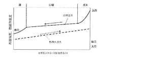
- FIG. 8 is a figure explaining an example of the temperature distribution in the intermediate heat exchanger 21a at the time of heating operation of the air conditioning apparatus in Embodiment 1 of this invention.
- the horizontal axis represents the specific enthalpy.
- the vertical axis represents the refrigerant temperature and the heat medium temperature.
- the high-temperature and high-pressure gas refrigerant that has flowed into the intermediate heat exchanger 21a radiates heat to a heat medium having a low temperature, so that the refrigerant temperature decreases and becomes a two-phase refrigerant when the saturation temperature is reached.
- the temperature of the two-phase refrigerant decreases as the condensation proceeds and becomes a liquid refrigerant. Further, the refrigerant in the liquid state radiates heat to the heat medium having a low temperature, so that the refrigerant temperature is lowered. On the other hand, the temperature of the heat medium flowing into the intermediate heat exchanger 21a rises as the heat exchange progresses.
- FIG. 9 is a figure explaining an example of the temperature distribution in the heat exchanger 42 between refrigerant
- the temperatures of the medium-temperature and high-pressure liquid refrigerant flowing into the inter-refrigerant heat exchanger 42 decrease as the heat exchange progresses. Due to the characteristics of the non-azeotropic mixed refrigerant, the temperatures of the low-temperature and low-pressure two-phase refrigerant flowing into the inter-refrigerant heat exchanger 42 rise as the heat exchange progresses to become a gas refrigerant.
- the refrigerant flowing through the heat source side heat exchanger 13 is always in counterflow with respect to the air flow in the heating operation mode. Therefore, the temperature difference between the refrigerant and the air in the heat exchanger can be reduced, and the heat exchange efficiency can be improved. Further, the refrigerant flowing through the intermediate heat exchanger 21a is always a counterflow to the flow of the heat medium. Therefore, it is possible to reduce the temperature difference between the refrigerant in the heat exchanger and the heat medium that is the heat utilization medium, and improve the heat exchange efficiency.
- the refrigerant circulation circuit in the air conditioner 100 is circulated in the heating operation mode.
- the amount of the generated refrigerant can be reduced.
- the non-azeotropic mixed refrigerant is used as the refrigerant circulating in the refrigerant circulation circuit.
- the temperature difference decreases due to the temperature gradient while heat exchange utilizing latent heat proceeds, and the heat exchange performance deteriorates.
- the heat exchanger the flow path in which the refrigerant and the heat medium have a counterflow relationship makes it difficult for the temperature difference to decrease even if heat exchange proceeds. Therefore, the heat exchange performance can be improved.
- the refrigerant having a large temperature gradient is, for example, a non-azeotropic mixed refrigerant having a temperature gradient of 2° C. or higher.
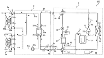
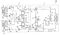
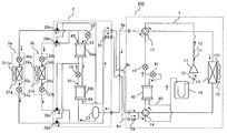
- FIG. 10 is a diagram schematically illustrating an example of the configuration of a circuit and the like in the air-conditioning apparatus according to Embodiment 2 of the present invention.
- each indoor unit 3 can be operated by selecting a cooling mode or a heating mode.
- differences from the air conditioning apparatus 100 of the first embodiment will be mainly described, and devices that perform the same operation as the devices described in the first embodiment are the same.
- the reference numeral is attached.
- the relay 2 has the intermediate heat exchanger 21a and the intermediate heat exchanger 21b, the third expansion device 16, and the pump 22a and the pump 22b. Further, the relay device 2 includes a heat medium flow path switching device 23a, a heat medium flow path switching device 23b, a heat medium flow path switching device 23c and a heat medium flow path switching device 23d, a heat medium feed pipe 61a and a heat medium feed pipe 61b. It also has a heat medium return pipe 62a and a heat medium return pipe 62b.
- the intermediate heat exchanger 21a serving as the first intermediate heat exchanger functions as a condenser in the heating operation, the cooling main operation and the heating main operation, and causes the refrigerant to radiate heat to heat the heat medium. Further, the intermediate heat exchanger 21a functions as an evaporator in the cooling operation, and causes the refrigerant to absorb heat to cool the heat medium.
- the intermediate heat exchanger 21b serving as the second intermediate heat exchanger functions as a condenser in the heating operation, and causes the refrigerant to radiate heat to heat the heat medium. Further, it functions as an evaporator in the cooling operation, the cooling main operation and the heating main operation, and makes the refrigerant absorb heat to cool the heat medium.
- the third expansion device 16 is a refrigerant flow rate adjusting device having a function as a pressure reducing valve or an expansion valve that reduces the pressure of the refrigerant, expands the refrigerant, and adjusts the amount of the refrigerant passing through.
- the third expansion device 16 may be configured to have a controllable opening such as an electronic expansion valve.
- the third expansion device 16 is installed in a pipe connecting between the intermediate heat exchanger 21a and the intermediate heat exchanger 21b.
- the pump 22a serving as the first pump is installed in the heat medium return pipe 62a that connects the intermediate heat exchanger 21a to the heat medium flow switching device 23b and the heat medium flow switching device 23d.
- the pump 22b serving as the second pump is installed in the heat medium return pipe 62b that connects the intermediate heat exchanger 21b to the heat medium flow switching device 23b and the heat medium flow switching device 23d.
- the heat medium flow path switching device 23a, the heat medium flow path switching device 23b, the heat medium flow path switching device 23c, and the heat medium flow path switching device 23d are configured by, for example, a three-way switching valve, and the heat medium in the heat medium circulation circuit. Switch the circulation route of.
- the heat medium flow path switching device 23a, the heat medium flow path switching device 23b, the heat medium flow path switching device 23c, and the heat medium flow path switching device 23d use either the heated heat medium or the cooled heat medium. Switching is performed so that the heat exchanger 31a and the use-side heat exchanger 31b pass therethrough.
- One of the heat medium flow switching device 23a and the heat medium flow switching device 23c is connected to the heat medium pipe 5, one is connected to the heat medium feed pipe 61a, and one is connected to the heat medium feed pipe 61b.
- the heat medium flow switching device 23a and the heat medium flow switching device 23c switch the flow channels on the heat medium inflow sides of the use-side heat exchanger 31a and the use-side heat exchanger 31b, respectively.
- one of the heat medium flow switching device 23b and the heat medium flow switching device 23d is connected to the heat medium pipe 5, one is connected to the heat medium return pipe 62a, and one is connected to the heat medium return pipe 62b. It The heat medium flow switching device 23b and the heat medium flow switching device 23d switch the flow channels on the heat medium outflow sides of the use-side heat exchanger 31a and the use-side heat exchanger 31b, respectively.
- the relay device 2 includes the refrigerant temperature sensor 81, the refrigerant temperature sensor 82, the refrigerant temperature sensor 83, the refrigerant temperature sensor 84, the heat medium temperature sensor 24a, the heat medium temperature sensor 24b, the heat medium temperature sensor 25a, and the heat medium temperature sensor 25b.
- the refrigerant temperature sensor 81 and the refrigerant temperature sensor 82 are sensors that detect the temperature of the refrigerant on the inlet side of the intermediate heat exchanger 21a and the intermediate heat exchanger 21b.
- the refrigerant temperature sensor 83 and the refrigerant temperature sensor 84 are sensors that detect the temperature of the refrigerant on the outlet side of the intermediate heat exchanger 21a and the intermediate heat exchanger 21b.
- the heat medium temperature sensor 24a and the heat medium temperature sensor 24b are sensors that detect the temperature of the heat medium on the inlet side of the intermediate heat exchanger 21a and the intermediate heat exchanger 21b.
- the heat medium temperature sensor 25a and the heat medium temperature sensor 25b are sensors that detect the temperature of the heat medium on the outlet side of the intermediate heat exchanger 21a and the intermediate heat exchanger 21b.
- the air conditioning apparatus 100 of the second embodiment can execute the cooling only operation, the heating only operation, the cooling main operation, and the heating main operation based on the instructions from the indoor unit 3a and the indoor unit 3b.
- the cooling only operation is an operation in which all the operating indoor units 3 are cooling.
- the heating only operation is an operation in which all the operating indoor units 3 are heating.
- the cooling-main operation the indoor unit 3 that is performing cooling and the indoor unit 3 that is performing heating are present at the same time, and of these, the operation relating to cooling is the main operation.
- the operation of the air conditioning apparatus 100 in each operation mode will be described along with the flow of refrigerant and the state of the refrigerant.
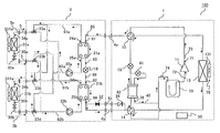
- FIG. 11 is a figure explaining an example of the flow of a refrigerant
- a cooling operation mode in which the indoor unit 3a and the indoor unit 3b are performing cooling will be described.
- the flow direction of the refrigerant is shown by solid arrows, and the flow direction of the heat medium is shown by broken arrows.
- the compressor 11 draws in low-temperature and low-pressure gas refrigerant, compresses it, and discharges high-temperature and high-pressure gas refrigerant.
- the high temperature and high pressure gas refrigerant discharged from the compressor 11 flows into the heat source side heat exchanger 13 via the first flow path switching device 12.
- the heat source side heat exchanger 13 exchanges heat between the outdoor air supplied from the outdoor fan 131 and the high-temperature and high-pressure gas refrigerant.
- the high-temperature and high-pressure gas refrigerant is cooled by heat exchange to become a medium-temperature and high-pressure liquid refrigerant.
- the medium-temperature and high-pressure liquid refrigerant cooled in the heat source side heat exchanger 13 flows into the inter-refrigerant heat exchanger 42 via the second flow path switching device 14.
- the inter-refrigerant heat exchanger 42 heats the low-temperature and low-pressure two-phase refrigerant flowing in the bypass circuit 40 and the medium-temperature and high-pressure liquid refrigerant flowing between the second flow path switching device 14 and the first expansion device 15. Exchange.
- the medium-temperature and high-pressure liquid refrigerant is cooled by heat exchange to become a low-temperature and high-pressure liquid refrigerant.
- the low-temperature and high-pressure liquid refrigerant cooled by the inter-refrigerant heat exchanger 42 flows into the first expansion device 15.
- the first expansion device 15 reduces the pressure of the low-temperature and high-pressure liquid refrigerant.
- the low-temperature and low-pressure two-phase refrigerant decompressed by the first expansion device 15 flows into the intermediate heat exchanger 21a via the first flow path switching device 12 and the outward pipe 4a.
- the intermediate heat exchanger 21a exchanges heat between the low-temperature and low-pressure two-phase refrigerant and the heat medium circulating in the heat medium circulation circuit by the pump 22a.
- the low-temperature and low-pressure gas refrigerant heated in the intermediate heat exchanger 21a passes through the return pipe 4b and the return pipe 4c, and is sucked into the compressor 11 again via the second flow path switching device 14 and the accumulator 19. It At this time, the opening/closing device 52 is open.
- the pump 22a sucks the heat medium and pressurizes it.
- the heat medium sent out by the pump 22a flows into the intermediate heat exchanger 21a.
- the intermediate heat exchanger 21a cold heat generated by the refrigerant on the refrigerant circulation circuit side is transferred to the heat medium, and the cooled heat medium passes through the heat medium feed pipe 61a.
- the pump 22b sucks the heat medium and pressurizes it.
- the heat medium sent out by the pump 22b flows into the intermediate heat exchanger 21b.
- the intermediate heat exchanger 21b cold heat by the refrigerant on the refrigerant circulation circuit side is transferred to the heat medium, and the cooled heat medium passes through the heat medium feed pipe 61b.
- the heat medium that has passed through the heat medium feed pipe 61a and the heat medium feed pipe 61b merges in each of the heat medium flow passage switching device 23a and the heat medium flow passage switching device 23c, and the heat on the use side heats through the heat medium pipe 5. It flows into the exchanger 31a and the use side heat exchanger 31b.
- the indoor unit 3a and the indoor unit 3b are performing the cooling operation, and the use side heat exchanger 31a and the use side heat exchanger 31b respectively cool the indoor air supplied from the indoor fan 311a and the indoor fan 311b and the low temperature. Heat is exchanged with the heat medium. Room air is cooled. The low temperature heat medium becomes a medium temperature heat medium.
- the medium-temperature heat medium heated by the use-side heat exchanger 31a and the use-side heat exchanger 31b is the heat medium flow rate adjusting device 32a, the heat medium flow rate adjusting device 32b, the heat medium flow path switching device 23c, and the heat medium flow path switching device. It is again sucked into the pump 22a and the pump 22b via the device 23b, the heat medium pipe 5, the heat medium return pipe 62a and the heat medium return pipe 62b.
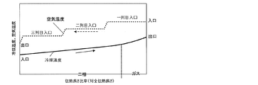
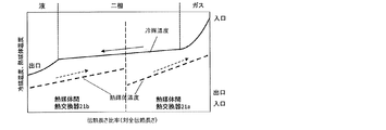
- FIG. 12 is a figure explaining an example of the temperature distribution in the intermediate heat exchanger 21a and the intermediate heat exchanger 21b at the time of cooling operation of the air conditioning apparatus in Embodiment 2 of this invention.
- the horizontal axis represents the specific enthalpy.
- the vertical axis represents the refrigerant temperature and the heat medium temperature.
- the heat medium inlet temperatures are substantially equal.
- the temperature of the low-temperature and low-pressure two-phase refrigerant flowing into the intermediate heat exchanger 21a rises with the progress of heat exchange due to the characteristics of the non-azeotropic mixed refrigerant.
- the refrigerant flows into the intermediate heat exchanger 21b in the two-phase state.
- the temperature of the two-phase refrigerant rises as the heat exchange progresses and becomes a gas refrigerant due to the characteristics of the non-azeotropic mixed refrigerant.
- the temperature of the gas refrigerant rises as the heat exchange progresses.
- the temperature of the heat medium flowing into the intermediate heat exchanger 21a and the intermediate heat exchanger 21b decreases as the heat exchange progresses.
- the refrigerant flowing through the heat source side heat exchanger 13 is always in counterflow with respect to the air flow in the cooling operation mode. Therefore, the temperature difference between the refrigerant and the air in the heat exchanger can be reduced, and the heat exchange efficiency can be improved. Further, the refrigerant flowing through the intermediate heat exchanger 21a and the intermediate heat exchanger 21b is always a counterflow to the flow of the heat medium. Therefore, it is possible to reduce the temperature difference between the refrigerant in the heat exchanger and the heat medium that is the heat utilization medium, and improve the heat exchange efficiency.
- the pressure loss of the low pressure portion can be reduced by reducing the flow rate of the main refrigerant without heat loss.
- the return piping 4b and the return piping 4c are arranged in parallel, and the opening/closing device 52 provided in the return piping 4c is opened to allow the refrigerant to flow through both the return piping 4b and the return piping 4c. .. Therefore, the cross-sectional area of the pipe through which the low-temperature and low-pressure two-phase refrigerant or the gas refrigerant passes increases, and the pressure loss can be reduced, so that the performance deterioration can be suppressed.
- FIG. 13 is a diagram illustrating an example of the flow of the refrigerant during the heating only operation of the air-conditioning apparatus according to Embodiment 2 of the present invention.
- a heating only operation mode in which the indoor unit 3a and the indoor unit 3b perform heating will be described.
- the flow direction of the refrigerant is shown by solid arrows, and the flow direction of the heat medium is shown by broken arrows.
- the compressor 11 draws in low-temperature and low-pressure gas refrigerant, compresses it, and discharges high-temperature and high-pressure gas refrigerant.
- the high-temperature and high-pressure gas refrigerant discharged from the compressor 11 flows into the intermediate heat exchanger 21a via the first flow path switching device 12 and the outward pipe 4a.
- the intermediate heat exchanger 21a exchanges heat between the high-temperature and high-pressure gas refrigerant and the heat medium circulating in the heat medium circulation circuit by the pump 22a.
- the high-temperature and high-pressure gas refrigerant is cooled by heat exchange to become a medium-temperature and high-pressure liquid refrigerant.
- the liquid refrigerant cooled in the intermediate heat exchanger 21a passes through the return pipe 4b.
- the opening/closing device 52 is closed, and the refrigerant does not pass through the return pipe 4c.
- the liquid refrigerant further flows into the first expansion device 15 via the second flow path switching device 14 and the inter-refrigerant heat exchanger 42.
- the first expansion device 15 reduces the pressure of the medium-temperature and high-pressure liquid refrigerant.
- the low-temperature and low-pressure two-phase refrigerant decompressed by the first expansion device 15 flows into the heat source side heat exchanger 13 via the first flow path switching device 12.
- the heat source side heat exchanger 13 exchanges heat between the outdoor air supplied from the outdoor fan 131 and the low-temperature and low-pressure two-phase refrigerant.
- the low-temperature and low-pressure gas refrigerant heated by the heat source side heat exchanger 13 is sucked into the compressor 11 again via the second flow path switching device 14 and the accumulator 19.
- the pump 22a sucks the heat medium and pressurizes it.
- the heat medium sent out by the pump 22a flows into the intermediate heat exchanger 21a.
- the heat generated by the refrigerant on the refrigerant circulation circuit side is transferred to the heat medium, and the heated heat medium passes through the heat medium feed pipe 61a.
- the pump 22b sucks the heat medium and pressurizes it.
- the heat medium sent out by the pump 22b flows into the intermediate heat exchanger 21b.
- the heat generated by the refrigerant on the refrigerant circulation circuit side is transferred to the heat medium, and the heated heat medium passes through the heat medium feed pipe 61b.
- the heat medium that has passed through the heat medium feed pipe 61a and the heat medium feed pipe 61b merges in each of the heat medium flow passage switching device 23a and the heat medium flow passage switching device 23c, and the heat on the use side heats through the heat medium pipe 5. It flows into the exchanger 31a and the use side heat exchanger 31b.
- the indoor unit 3a and the indoor unit 3b are performing heating operation, and in the use side heat exchanger 31a and the use side heat exchanger 31b, the indoor air and high temperature of indoor air supplied from the indoor fan 311a and the indoor fan 311b, respectively. Heat is exchanged with the heat medium.
- the room air is heated.
- the high temperature heat medium becomes a medium temperature heat medium.
- the medium-temperature heat medium heated by the use-side heat exchanger 31a and the use-side heat exchanger 31b is the heat medium flow rate adjusting device 32a, the heat medium flow rate adjusting device 32b, the heat medium flow path switching device 23c, and the heat medium flow path switching device. It is again sucked into the pump 22a and the pump 22b via the device 23b, the heat medium pipe 5, the heat medium return pipe 62a and the heat medium return pipe 62b.
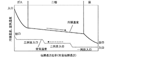
- FIG. 14 is a figure explaining an example of the temperature distribution in the intermediate heat exchanger 21a and the intermediate heat exchanger 21b at the time of heating only operation of the air conditioning apparatus in Embodiment 2 of this invention.
- the heat medium inlet temperatures are substantially equal.
- the horizontal axis represents the specific enthalpy.
- the vertical axis represents the refrigerant temperature and the heat medium temperature.
- the high-temperature and high-pressure gas refrigerant that has flowed into the intermediate heat exchanger 21a radiates heat to a heat medium having a low temperature, so that the refrigerant temperature decreases and becomes a two-phase refrigerant when the saturation temperature is reached.
- the refrigerant flows into the intermediate heat exchanger 21b in the two-phase state.
- the temperature of the two-phase refrigerant becomes a liquid refrigerant due to the characteristics of the non-azeotropic mixed refrigerant as the refrigerant temperature decreases as the condensation proceeds.
- the temperature of the liquid refrigerant further decreases as heat exchange proceeds.
- the temperature of the heat medium flowing into the intermediate heat exchanger 21a and the intermediate heat exchanger 21b rises as the heat exchange progresses.
- the refrigerant flowing through the heat source side heat exchanger 13 is always in counterflow with respect to the flow of air in the heating operation mode. Therefore, the temperature difference between the refrigerant and the air in the heat exchanger can be reduced, and the heat exchange efficiency can be improved. Further, the refrigerant flowing through the intermediate heat exchanger 21a and the intermediate heat exchanger 21b is always a counterflow to the flow of the heat medium. Therefore, it is possible to reduce the temperature difference between the refrigerant in the heat exchanger and the heat medium that is the heat utilization medium, and improve the heat exchange efficiency.
- the refrigerant circulation circuit in the air conditioner 100 is circulated in the heating operation mode.
- the amount of the generated refrigerant can be reduced.
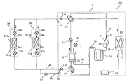
- FIG. 15 is a figure explaining an example of the flow of a refrigerant
- a cooling-main operation mode in which the indoor unit 3a performs heating and the indoor unit 3b performs cooling will be described.
- the compressor 11 draws in low-temperature and low-pressure gas refrigerant, compresses it, and discharges high-temperature and high-pressure gas refrigerant.
- the high temperature and high pressure gas refrigerant discharged from the compressor 11 flows into the heat source side heat exchanger 13 via the first flow path switching device 12.
- the heat source side heat exchanger 13 exchanges heat between the outdoor air supplied from the outdoor fan 131 and the high-temperature and high-pressure gas refrigerant.
- the high-temperature and high-pressure gas refrigerant is cooled by heat exchange and becomes a medium-temperature and high-pressure two-phase refrigerant.
- the medium-temperature and high-pressure two-phase refrigerant cooled in the heat source side heat exchanger 13 includes the second flow path switching device 14, the inter-refrigerant heat exchanger 42, the first expansion device 15, and the first flow path switching device 12. Then, it passes through the forward pipe 4a and flows into the intermediate heat exchanger 21a.
- the intermediate heat exchanger 21a exchanges heat between the medium-temperature and high-pressure two-phase refrigerant and the heat medium circulating in the heat medium circulation circuit by the pump 22a.
- the medium-temperature and high-pressure two-phase refrigerant is condensed in the intermediate heat exchanger 21a to become the medium-temperature and high-pressure two-phase refrigerant or liquid refrigerant.
- the medium-temperature and high-pressure two-phase refrigerant or liquid refrigerant flows into the third expansion device 16.
- the third expansion device 16 reduces the pressure of the medium-temperature and high-pressure two-phase refrigerant or liquid refrigerant.
- the low-temperature and low-pressure two-phase refrigerant decompressed by the third expansion device 16 flows into the intermediate heat exchanger 21b.
- the intermediate heat exchanger 21b exchanges heat between the low-temperature and low-pressure two-phase refrigerant and the heat medium circulating in the heat medium circulation circuit by the pump 22b.
- the low-temperature and low-pressure two-phase refrigerant or gas refrigerant heated in the intermediate heat exchanger 21b passes through the return pipe 4b and the return pipe 4c, and passes through the second flow path switching device 14 and the accumulator 19 to the compressor 11 Is inhaled again.
- the pump 22a sucks the heat medium and pressurizes it.
- the heat medium sent out by the pump 22a flows into the intermediate heat exchanger 21a.
- the intermediate heat exchanger 21a the heat generated by the refrigerant on the refrigerant circulation circuit side is transferred to the heat medium, and the heated heat medium passes through the heat medium feed pipe 61a, the heat medium flow switching device 23a, and the heat medium pipe 5, It flows into the utilization side heat exchanger 31a.
- the indoor unit 3a is performing heating operation, and the indoor air supplied from the indoor fan 311a and the high-temperature heat medium are heat-exchanged in the usage-side heat exchanger 31a.
- the room air is heated.
- the high temperature heat medium becomes a medium temperature heat medium.
- the medium-temperature heat medium cooled in the use-side heat exchanger 31a is sucked into the pump 22a again via the heat medium flow rate adjusting device 32a, the heat medium pipe 5, the heat medium flow switching device 23b, and the heat medium return pipe 62a. To be done.
- the pump 22b sucks the heat medium and pressurizes it.
- the heat medium sent out by the pump 22b flows into the intermediate heat exchanger 21b.
- the intermediate heat exchanger 21b cold heat by the refrigerant on the refrigerant circulation circuit side is transferred to the heat medium, and the cooled heat medium is transferred via the heat medium feed pipe 61b, the heat medium flow path switching device 23b and the heat medium pipe 5. It flows into the utilization side heat exchanger 31b.
- the indoor unit 3b is performing the cooling operation, and the indoor air supplied from the indoor fan 311b and the low-temperature heat medium are heat-exchanged in the use-side heat exchanger 31b. Room air is cooled.
- the low temperature heat medium becomes a medium temperature heat medium.
- the medium-temperature heat medium heated in the use-side heat exchanger 31b is sucked into the pump 22b again via the heat medium flow rate adjusting device 32b, the heat medium pipe 5, the heat medium flow path switching device 23d, and the heat medium return pipe 62b. To be done.
- the refrigerant flowing through the heat source side heat exchanger 13 is always in counterflow with respect to the air flow in the cooling main operation mode. Therefore, the temperature difference between the refrigerant and the air in the heat exchanger can be reduced, and the heat exchange efficiency can be improved. Further, the refrigerant flowing through the intermediate heat exchanger 21a and the intermediate heat exchanger 21b is always a counterflow to the flow of the heat medium. Therefore, it is possible to reduce the temperature difference between the refrigerant in the heat exchanger and the heat medium that is the heat utilization medium, and improve the heat exchange efficiency.
- the return piping 4b and the return piping 4c are arranged in parallel, and the opening/closing device 52 provided in the return piping 4c is opened to allow the refrigerant to flow through both the return piping 4b and the return piping 4c. ..
- the cross-sectional area of the pipe through which the low-temperature and low-pressure two-phase refrigerant or the gas refrigerant passes increases, and the pressure loss on the low-pressure side in the refrigerant circulation circuit can be reduced, so that performance deterioration can be suppressed.
- FIG. 16 is a diagram illustrating an example of a refrigerant flow and the like during heating-main operation of the air-conditioning apparatus according to Embodiment 2 of the present invention.
- a heating-main operation mode in which the indoor unit 3a performs heating and the indoor unit 3b performs cooling will be described.
- the compressor 11 draws in low-temperature and low-pressure gas refrigerant, compresses it, and discharges high-temperature and high-pressure gas refrigerant. It flows into the intermediate heat exchanger 21a via the first flow path switching device 12 and the outward pipe 4a.
- the intermediate heat exchanger 21a exchanges heat between the high-temperature and high-pressure gas refrigerant and the heat medium circulating in the heat medium circulation circuit by the pump 22a.
- the high-temperature and high-pressure gas refrigerant is cooled by heat exchange and becomes a medium-temperature and high-pressure two-phase refrigerant or liquid refrigerant.
- the two-phase refrigerant or the liquid refrigerant cooled by the intermediate heat exchanger 21a flows into the third expansion device 16.
- the third expansion device 16 reduces the pressure of the medium-temperature and high-pressure two-phase refrigerant or liquid refrigerant.
- the low-temperature and low-pressure two-phase refrigerant decompressed by the third expansion device 16 flows into the intermediate heat exchanger 21b.
- the intermediate heat exchanger 21b exchanges heat between the low-temperature and low-pressure two-phase refrigerant and the heat medium circulating in the heat medium circulation circuit by the pump 22b.
- the low-temperature and low-pressure two-phase refrigerant heated by the intermediate heat exchanger 21b passes through the return pipe 4b and the return pipe 4c, and passes through the second flow path switching device 14 and the inter-refrigerant heat exchanger 42 to generate the first refrigerant. It flows into the expansion device 15.
- the first expansion device 15 reduces the pressure of the low-temperature and low-pressure two-phase refrigerant.
- the low-temperature and low-pressure two-phase refrigerant decompressed by the first expansion device 15 flows into the heat source side heat exchanger 13 via the first flow path switching device 12.
- the heat source side heat exchanger 13 exchanges heat between the outdoor air supplied from the outdoor fan 131 and the low-temperature and low-pressure two-phase refrigerant.
- the low-temperature and low-pressure gas refrigerant or the two-phase refrigerant heated by the heat source side heat exchanger 13 is sucked into the compressor 11 again via the second flow path switching device 14 and the accumulator 19.
- the pump 22a sucks the heat medium and pressurizes it.
- the heat medium sent out by the pump 22a flows into the intermediate heat exchanger 21a.
- the intermediate heat exchanger 21a the heat generated by the refrigerant on the refrigerant circulation circuit side is transferred to the heat medium, and the heated heat medium passes through the heat medium feed pipe 61a, the heat medium flow switching device 23a, and the heat medium pipe 5, It flows into the utilization side heat exchanger 31a.
- the indoor unit 3a is performing heating operation, and the indoor air supplied from the indoor fan 311a and the high-temperature heat medium are heat-exchanged in the usage-side heat exchanger 31a.
- the room air is heated.
- the high temperature heat medium becomes a medium temperature heat medium.
- the medium-temperature heat medium cooled in the use-side heat exchanger 31a is sucked into the pump 22a again via the heat medium flow rate adjusting device 32a, the heat medium pipe 5, the heat medium flow switching device 23b, and the heat medium return pipe 62a. To be done.
- the pump 22b sucks the heat medium and pressurizes it.
- the heat medium sent out by the pump 22b flows into the intermediate heat exchanger 21b.
- the intermediate heat exchanger 21b cold heat by the refrigerant on the refrigerant circulation circuit side is transferred to the heat medium, and the cooled heat medium is transferred via the heat medium feed pipe 61b, the heat medium flow path switching device 23b and the heat medium pipe 5. It flows into the utilization side heat exchanger 31b.
- the indoor unit 3b is performing the cooling operation, and the indoor air supplied from the indoor fan 311b and the low-temperature heat medium are heat-exchanged in the use-side heat exchanger 31b. Room air is cooled.
- the low temperature heat medium becomes a medium temperature heat medium.
- the medium-temperature heat medium heated in the use-side heat exchanger 31b is sucked into the pump 22b again via the heat medium flow rate adjusting device 32b, the heat medium pipe 5, the heat medium flow path switching device 23d, and the heat medium return pipe 62b. To be done.
- the refrigerant flowing through the heat source side heat exchanger 13 is always in counterflow to the air flow in the heating main operation mode. Therefore, the temperature difference between the refrigerant and the air in the heat exchanger can be reduced, and the heat exchange efficiency can be improved. Further, the refrigerant flowing through the intermediate heat exchanger 21a and the intermediate heat exchanger 21b is always a counterflow to the flow of the heat medium. Therefore, it is possible to reduce the temperature difference between the refrigerant in the heat exchanger and the heat medium that is the heat utilization medium, and improve the heat exchange efficiency.
- the return piping 4b and the return piping 4c are arranged in parallel, and the opening/closing device 52 provided in the return piping 4c is opened to allow the refrigerant to flow through both the return piping 4b and the return piping 4c. ..
- the cross-sectional area of the pipe through which the low-temperature and low-pressure two-phase refrigerant or the gas refrigerant passes increases, and the pressure loss on the low-pressure side in the refrigerant circulation circuit can be reduced, so that performance deterioration can be suppressed.
- FIG. 17 is a diagram schematically showing an example of the configuration of a circuit and the like in the air-conditioning apparatus according to Embodiment 3 of the present invention.
- each indoor unit 3 can operate by selecting a cooling mode or a heating mode, respectively.
- differences from the air conditioner 100 of the first embodiment will be mainly described, and devices that perform the same operation as the devices described in the first embodiment will be described. The same symbols are attached.
- the outdoor unit 1 and the indoor unit 3 are connected by the forward pipe 4a, the return pipe 4b, and the return pipe 4c to form a refrigerant circulation circuit.
- FIG. 17 shows an example in which two indoor units 3a and 3b are connected in parallel with the outdoor unit 1, but the number of indoor units 3 may be three or more.
- the outdoor unit 1 of the third embodiment has an opening/closing device 17a and an opening/closing device 17b.
- the opening/closing device 17a and the opening/closing device 17b control passage of the refrigerant between the outdoor unit 1 and the indoor unit 3a and the indoor unit 3b. For example, when there is a refrigerant leak in a portion other than the outdoor unit 1, the opening/closing device 17a and the opening/closing device 17b are closed to confine the refrigerant in the outdoor unit 1.
- the indoor unit 3a and the indoor unit 3b according to the third embodiment include a use side heat exchanger 31a, a use side heat exchanger 31b, a first indoor expansion device 36a, a first indoor expansion device 36b, and a second indoor space, respectively. It has an expansion device 37a and a second indoor expansion device 37b.
- the first indoor expansion device 36a and the first indoor expansion device 36b, and the second indoor expansion device 37a and the second indoor expansion device 37b each have a function as a pressure reducing valve or expansion valve that decompresses and expands the refrigerant. Is.
- the first indoor expansion device 36a and the first indoor expansion device 36b, and the second indoor expansion device 37a and the second indoor expansion device 37b can be controlled in their opening degree, for example, like an electronic expansion valve. It should consist of one.
- the first indoor expansion device 36a and the first indoor expansion device 36b are arranged in a pipe between the outward pipe 4a and the use side heat exchanger 31a and the use side heat exchanger 31b.
- the second indoor expansion device 37a and the second indoor expansion device 37b are arranged in a pipe between the return pipe 4b and the return pipe 4c and the use side heat exchanger 31a and the use side heat exchanger 31b. ing.
- FIG. 18 is a diagram illustrating an example of a refrigerant flow and the like during a cooling operation of the air-conditioning apparatus according to Embodiment 3 of the present invention.
- a cooling operation mode in which the indoor unit 3a and the indoor unit 3b are performing cooling will be described.
- the compressor 11 draws in low-temperature and low-pressure gas refrigerant, compresses it, and discharges high-temperature and high-pressure gas refrigerant.
- the high temperature and high pressure gas refrigerant discharged from the compressor 11 flows into the heat source side heat exchanger 13 via the first flow path switching device 12.
- the heat source side heat exchanger 13 exchanges heat between the outdoor air supplied from the outdoor fan 131 and the high-temperature and high-pressure gas refrigerant.
- the high-temperature and high-pressure gas refrigerant is cooled by heat exchange to become a medium-temperature and high-pressure liquid refrigerant.
- the inter-refrigerant heat exchanger 42 heats the low-temperature and low-pressure two-phase refrigerant flowing in the bypass circuit 40 and the medium-temperature and high-pressure liquid refrigerant flowing between the second flow path switching device 14 and the first expansion device 15. Exchange.
- the medium-temperature and high-pressure liquid refrigerant is cooled by heat exchange to become a low-temperature and high-pressure liquid refrigerant.
- the low-temperature and high-pressure liquid refrigerant cooled in the inter-refrigerant heat exchanger 42 passes through the first expansion device 15, the first flow path switching device 12, the opening/closing device 17a, and the outgoing pipe 4a to generate the first indoor expansion device. 36a and the first indoor expansion device 36b.
- the first indoor expansion device 36a and the first indoor expansion device 36b decompress low-temperature and high-pressure liquid refrigerant.
- the low-temperature and low-pressure two-phase refrigerant decompressed by the first indoor expansion device 36a and the first indoor expansion device 36b flows into the usage-side heat exchanger 31a and the usage-side heat exchanger 31b.
- the indoor unit 3a and the indoor unit 3b are performing the cooling operation, and the use-side heat exchanger 31a and the use-side heat exchanger 31b are supplied from the low-temperature and low-pressure two-phase refrigerant and the indoor fan 311a and the indoor fan 311b. Heat is exchanged with the room air.
- the low temperature and low pressure two-phase refrigerant is heated by heat exchange to become a low temperature and low pressure gas refrigerant.
- the low-temperature and low-pressure gas refrigerant passes through the return pipe 4b and the return pipe 4c through the second indoor expansion device 37a and the second indoor expansion device 37b.
- the low-temperature and low-pressure gas refrigerant further passes through the second flow path switching device 14 and the accumulator 19, and is sucked into the compressor 11 again.
- the opening/closing device 52 is open.
- the refrigerant flowing through the heat source side heat exchanger 13 is always in counterflow to the air flow in the cooling operation mode. Therefore, the temperature difference between the refrigerant and the air in the heat exchanger can be reduced, and the heat exchange efficiency can be improved. Further, the refrigerant flowing through the use-side heat exchanger 31a and the use-side heat exchanger 31b always becomes a counterflow with respect to the flow of indoor air. Therefore, it is possible to reduce the temperature difference between the refrigerant in the heat exchanger and the room air that serves as the heat utilization medium, and improve the heat exchange efficiency.
- the return piping 4b and the return piping 4c are arranged in parallel, and the opening/closing device 52 provided in the return piping 4c is opened to allow the refrigerant to flow through both the return piping 4b and the return piping 4c. .. Therefore, the cross-sectional area of the pipe through which the low-temperature and low-pressure two-phase refrigerant or the gas refrigerant passes increases, and the pressure loss can be reduced, so that the performance deterioration can be suppressed.
- FIG. 19 is a diagram illustrating an example of the flow of the refrigerant during the heating operation of the air-conditioning apparatus according to Embodiment 3 of the present invention.
- a heating operation mode in which the indoor unit 3a and the indoor unit 3b perform heating will be described.
- the compressor 11 draws in low-temperature and low-pressure gas refrigerant, compresses it, and discharges high-temperature and high-pressure gas refrigerant.
- the high-temperature and high-pressure refrigerant gas discharged from the compressor 11 passes through the first flow path switching device 12, the opening/closing device 17a, the outward pipe 4a, the first indoor expansion device 36a, and the first indoor expansion device 36b. , Into the use side heat exchanger 31a and the use side heat exchanger 31b.
- the indoor unit 3a and the indoor unit 3b are performing the heating operation, and the use-side heat exchanger 31a and the use-side heat exchanger 31b are supplied from the high-temperature and high-pressure gas refrigerant and the indoor fan 311a and the indoor fan 311b. Heat is exchanged with the room air.
- the high-temperature and high-pressure gas refrigerant is cooled by heat exchange to become a medium-temperature and high-pressure liquid refrigerant.
- the medium-temperature and high-pressure liquid refrigerant passes through the return pipe 4b via the second indoor expansion device 37a and the second indoor expansion device 37b.
- the opening/closing device 52 is closed, and the refrigerant does not pass through the return pipe 4c.
- the medium-temperature and high-pressure liquid refrigerant further flows into the first expansion device 15 via the second flow path switching device 14 and the inter-refrigerant heat exchanger 42.
- the first expansion device 15 reduces the pressure of the medium-temperature and high-pressure liquid refrigerant.
- the low-temperature and low-pressure two-phase refrigerant decompressed by the first expansion device 15 flows into the heat source side heat exchanger 13 via the first flow path switching device 12.
- the heat source side heat exchanger 13 exchanges heat between the outdoor air supplied from the outdoor fan 131 and the low-temperature and low-pressure two-phase refrigerant.
- the low-temperature and low-pressure gas refrigerant or the two-phase refrigerant heated by the heat source side heat exchanger 13 is sucked into the compressor 11 again via the second flow path switching device 14 and the accumulator 19.
- the refrigerant flowing through the heat source side heat exchanger 13 is always in counterflow to the air flow in the heating operation mode. Therefore, the temperature difference between the refrigerant and the air in the heat exchanger can be reduced, and the heat exchange efficiency can be improved. Further, the refrigerant flowing through the use-side heat exchanger 31a and the use-side heat exchanger 31b always becomes a counterflow with respect to the flow of indoor air. Therefore, it is possible to reduce the temperature difference between the refrigerant in the heat exchanger and the room air that serves as the heat utilization medium, and improve the heat exchange efficiency.
- the refrigerant circulation circuit in the air conditioner 100 is circulated in the heating operation mode.
- the amount of the generated refrigerant can be reduced.
- FIG. 20 is a diagram schematically illustrating an example of the configuration of circuits and the like in the air-conditioning apparatus according to Embodiment 4 of the present invention.
- each indoor unit 3 can operate by selecting a cooling mode or a heating mode.
- differences from the air conditioner 100 of the first embodiment will be mainly described, and devices that perform the same operation as the devices described in the first embodiment will be described. The same symbols are attached.
- the outdoor unit 1 and the indoor unit 3 are connected by the forward pipe 4a, the return pipe 4b, and the return pipe 4c to form a refrigerant circulation circuit.
- FIG. 20 shows an example in which two indoor units 3a and 3b are connected in parallel with the outdoor unit 1, but the number of indoor units 3 may be three or more.
- the repeater 2 of the fourth embodiment is installed, for example, in a non-air-conditioned space in the building, which is different from the air-conditioned space in which the indoor unit 3 is installed.
- the relay device 2 includes a gas-liquid separator 27, an inter-refrigerant heat exchanger 28a and an inter-refrigerant heat exchanger 28b, a third expansion device 16, a fourth expansion device 18, a refrigerant flow path switching device 26a, and a refrigerant flow path switching. It has a device 26b, a refrigerant flow path switching device 26c, and a refrigerant flow path switching device 26d.
- the inter-refrigerant heat exchanger 28a and the inter-refrigerant heat exchanger 28b are configured by, for example, a double-tube heat exchanger.
- the inter-refrigerant heat exchanger 28a and the inter-refrigerant heat exchanger 28b exchange heat between the medium-temperature and high-pressure refrigerant flowing out of the gas-liquid separator 27 and the low-temperature and low-pressure refrigerant flowing out of the fourth expansion device 18.
- the refrigerant channel switching device 26 (refrigerant channel switching device 26a, refrigerant channel switching device 26b, refrigerant channel switching device 26c, and refrigerant channel switching device 26d) is composed of, for example, a three-way switching valve.
- the refrigerant flow path switching device 26 switches the refrigerant flow paths in the cooling operation mode and the heating operation mode.
- One of the refrigerant flow path switching device 26a and the refrigerant flow path switching device 26b is connected to the indoor unit 3, one is connected to the inter-refrigerant heat exchanger 28a, and one is connected to one end of the gas-liquid separator 27.
- the refrigerant flow channel switching device 26a and the refrigerant flow channel switching device 26b switch the flow channels on the refrigerant inflow side of the use side heat exchanger 31a and the use side heat exchanger 31b, respectively. Further, one of the refrigerant flow path switching device 26c and the refrigerant flow path switching device 26d is connected to the indoor unit 3, and the other is connected to a pipe connecting the inter-refrigerant heat exchanger 28a and the inter-refrigerant heat exchanger 28b, One is connected to the return pipe 4b and the return pipe 4c. The refrigerant flow channel switching device 26c and the refrigerant flow channel switching device 26d switch the flow channels on the refrigerant outflow side of the use side heat exchanger 31a and the use side heat exchanger 31b, respectively.
- the repeater 2 of the fourth embodiment has a refrigerant temperature sensor 81, a refrigerant temperature sensor 82, a refrigerant temperature sensor 83, and a refrigerant temperature sensor 84.
- the refrigerant temperature sensor 81 is a sensor that detects the temperature of the refrigerant on the inlet side of the inter-refrigerant heat exchanger 28b.
- the refrigerant temperature sensor 82 is a sensor that detects the temperature of the refrigerant on the outlet side of the inter-refrigerant heat exchanger 28a.
- the refrigerant temperature sensor 83 is a sensor that detects the temperature of the heat medium on the inlet side of the inter-refrigerant heat exchanger 28a.
- the refrigerant temperature sensor 84 is a sensor that detects the temperature of the heat medium on the outlet side of the inter-refrigerant heat exchanger 28b.
- FIG. 21 is a diagram illustrating an example of the flow of the refrigerant during the cooling operation of the air-conditioning apparatus according to Embodiment 4 of the present invention.
- a cooling operation mode in which the indoor unit 3a and the indoor unit 3b are performing cooling will be described.
- the compressor 11 draws in low-temperature and low-pressure gas refrigerant, compresses it, and discharges high-temperature and high-pressure gas refrigerant.
- the high-temperature and high-pressure refrigerant gas discharged from the compressor 11 flows into the heat source side heat exchanger 13 via the first flow path switching device 12.
- the heat source side heat exchanger 13 exchanges heat between the outdoor air supplied from the outdoor fan 131 and the high-temperature and high-pressure gas refrigerant.
- the high-temperature and high-pressure gas refrigerant is cooled by heat exchange to become a medium-temperature and high-pressure liquid refrigerant.
- the inter-refrigerant heat exchanger 42 heats the low-temperature and low-pressure two-phase refrigerant flowing in the bypass circuit 40 and the medium-temperature and high-pressure liquid refrigerant flowing between the second flow path switching device 14 and the first expansion device 15. Exchange.
- the medium-temperature and high-pressure liquid refrigerant is cooled by heat exchange to become a low-temperature and high-pressure liquid refrigerant.
- the medium-temperature and high-pressure liquid refrigerant passes through the third expansion device 16, the inter-refrigerant heat exchanger 28a, the refrigerant flow path switching device 26a, and the refrigerant flow path switching device 26b, and the first indoor expansion device 36a and the first indoor expansion device 36a. It flows into the indoor expansion device 36b.
- the indoor unit 3a and the indoor unit 3b are performing the cooling operation, and the use-side heat exchanger 31a and the use-side heat exchanger 31b are supplied from the low-temperature and low-pressure two-phase refrigerant and the indoor fan 311a and the indoor fan 311b.
- Heat is exchanged with the room air.
- the low temperature and low pressure two-phase refrigerant is heated by heat exchange to become a low temperature and low pressure gas refrigerant.
- the low-temperature and low-pressure gas refrigerant flows into the return pipes 4b and 4c through the second indoor expansion device 37a, the second indoor expansion device 37b, the refrigerant flow path switching device 26c, and the refrigerant flow path switching device 26d.
- the low-temperature and low-pressure gas refrigerant is sucked into the compressor 11 again via the second flow path switching device 14 and the accumulator 19. At this time, the opening/closing device 52 is open.
- the refrigerant flowing through the heat source side heat exchanger 13 is always in counterflow with respect to the air flow in the cooling operation mode. Therefore, the temperature difference between the refrigerant and the air in the heat exchanger can be reduced, and the heat exchange efficiency can be improved. Further, the refrigerant flowing through the use-side heat exchanger 31a and the use-side heat exchanger 31b always becomes a counterflow with respect to the flow of indoor air. Therefore, it is possible to reduce the temperature difference between the refrigerant in the heat exchanger and the room air that serves as the heat utilization medium, and improve the heat exchange efficiency.
- the return piping 4b and the return piping 4c are arranged in parallel, and the opening/closing device 52 provided in the return piping 4c is opened to allow the refrigerant to flow through both the return piping 4b and the return piping 4c. .. Therefore, the cross-sectional area of the pipe through which the low-temperature and low-pressure two-phase refrigerant or the gas refrigerant passes increases, and the pressure loss can be reduced, so that the performance deterioration can be suppressed.
- FIG. 22 is a diagram illustrating an example of the flow of the refrigerant during the heating operation of the air-conditioning apparatus according to Embodiment 4 of the present invention.
- a heating operation mode in which the indoor unit 3a and the indoor unit 3b are heating will be described.
- the compressor 11 draws in low-temperature and low-pressure gas refrigerant, compresses it, and discharges high-temperature and high-pressure gas refrigerant.
- the high-temperature and high-pressure refrigerant gas discharged from the compressor 11 flows into the gas-liquid separator 27 via the first flow path switching device 12, the opening/closing device 17a, and the outgoing pipe 4a.
- the high-temperature and high-pressure refrigerant gas that has flowed into the gas-liquid separator 27 is further passed through the refrigerant channel switching device 26a and the refrigerant channel switching device 26b, the first indoor expansion device 36a, and the first indoor expansion device 36b. , Into the use side heat exchanger 31a and the use side heat exchanger 31b.
- the indoor unit 3a and the indoor unit 3b are performing heating operation, and the use-side heat exchanger 31a and the use-side heat exchanger 31b are supplied from the high-temperature and high-pressure gas refrigerant and the indoor fan 311a and the indoor fan 311b.
- Heat is exchanged with the room air.
- the high-temperature and high-pressure gas refrigerant is cooled by heat exchange to become a medium-temperature and high-pressure liquid refrigerant.
- the high-temperature and high-pressure gas refrigerant is cooled by heat exchange to become a medium-temperature and high-pressure liquid refrigerant.
- the medium-temperature and high-pressure liquid refrigerant passes through the return pipe 4b through the second indoor expansion device 37a, the second indoor expansion device 37b, the refrigerant flow path switching device 26c, and the refrigerant flow path switching device 26d.
- the opening/closing device 52 is closed, and the refrigerant does not pass through the return pipe 4c.
- the medium-temperature and high-pressure liquid refrigerant further flows into the first expansion device 15 via the second flow path switching device 14 and the inter-refrigerant heat exchanger 42.
- the first expansion device 15 reduces the pressure of the medium-temperature and high-pressure liquid refrigerant.
- the low-temperature and low-pressure two-phase refrigerant decompressed by the first expansion device 15 flows into the heat source side heat exchanger 13 via the first flow path switching device 12.
- the heat source side heat exchanger 13 exchanges heat between the outdoor air supplied from the outdoor fan 131 and the low-temperature and low-pressure two-phase refrigerant.
- the low-temperature and low-pressure gas refrigerant or the two-phase refrigerant heated by the heat source side heat exchanger 13 is sucked into the compressor 11 again via the second flow path switching device 14 and the accumulator 19.
- the refrigerant flowing through the heat source side heat exchanger 13 is always in counterflow to the air flow in the heating operation mode. Therefore, the temperature difference between the refrigerant and the air in the heat exchanger can be reduced, and the heat exchange efficiency can be improved. Further, the refrigerant flowing through the use-side heat exchanger 31a and the use-side heat exchanger 31b always becomes a counterflow with respect to the flow of indoor air. Therefore, it is possible to reduce the temperature difference between the refrigerant in the heat exchanger and the room air that serves as the heat utilization medium, and improve the heat exchange efficiency.
- the refrigerant circulation circuit in the air conditioner 100 is circulated in the heating operation mode.
- the amount of the generated refrigerant can be reduced.
Abstract
Ce dispositif de climatisation comprend : une unité de source de chaleur qui produit une énergie thermique positive ou une énergie thermique négative et permet à un fluide frigorigène du transférer; une unité d'utilisation de chaleur qui effectue un échange de chaleur avec l'énergie thermique positive ou l'énergie thermique négative transférée depuis l'unité de source de chaleur par le fluide frigorigène et fournit celle-ci à une charge de chaleur; une tuyauterie de distribution qui relie l'unité de source de chaleur et l'unité d'utilisation de chaleur et permet au fluide frigorigène de s'écouler du côté de l'unité de source de chaleur au côté de l'unité d'utilisation de chaleur; une tuyauterie de retour qui a une pluralité de tuyaux qui relient l'unité de source de chaleur et l'unité d'utilisation de chaleur en parallèle et permettent au fluide frigorigène de s'écouler du côté de l'unité d'utilisation de chaleur au côté de l'unité de source de chaleur; un dispositif d'ouverture/fermeture qui est installé dans au moins un tuyau de la tuyauterie de retour et qui commande la quantité de fluide frigorigène passant à travers la tuyauterie de retour; et un dispositif de commande qui effectue une commande pour ouvrir le dispositif d'ouverture/fermeture pendant l'opération de refroidissement et fermer le dispositif d'ouverture/fermeture pendant l'opération de chauffage.
Priority Applications (5)
| Application Number | Priority Date | Filing Date | Title |
|---|---|---|---|
| EP19917030.9A EP3933300A4 (fr) | 2019-02-27 | 2019-02-27 | Dispositif de climatisation |
| PCT/JP2019/007628 WO2020174618A1 (fr) | 2019-02-27 | 2019-02-27 | Dispositif de climatisation |
| US17/425,323 US20220090815A1 (en) | 2019-02-27 | 2019-02-27 | Air-conditioning apparatus |
| JP2019528779A JP6576603B1 (ja) | 2019-02-27 | 2019-02-27 | 空気調和装置 |
| CN201980092497.5A CN113439188B (zh) | 2019-02-27 | 2019-02-27 | 空调装置 |
Applications Claiming Priority (1)
| Application Number | Priority Date | Filing Date | Title |
|---|---|---|---|
| PCT/JP2019/007628 WO2020174618A1 (fr) | 2019-02-27 | 2019-02-27 | Dispositif de climatisation |
Publications (1)
| Publication Number | Publication Date |
|---|---|
| WO2020174618A1 true WO2020174618A1 (fr) | 2020-09-03 |
Family
ID=67982814
Family Applications (1)
| Application Number | Title | Priority Date | Filing Date |
|---|---|---|---|
| PCT/JP2019/007628 WO2020174618A1 (fr) | 2019-02-27 | 2019-02-27 | Dispositif de climatisation |
Country Status (5)
| Country | Link |
|---|---|
| US (1) | US20220090815A1 (fr) |
| EP (1) | EP3933300A4 (fr) |
| JP (1) | JP6576603B1 (fr) |
| CN (1) | CN113439188B (fr) |
| WO (1) | WO2020174618A1 (fr) |
Families Citing this family (3)
| Publication number | Priority date | Publication date | Assignee | Title |
|---|---|---|---|---|
| CN114450541B (zh) * | 2019-09-30 | 2023-08-11 | 大金工业株式会社 | 冷冻循环装置 |
| CN112432396B (zh) * | 2020-09-30 | 2022-10-14 | 三花控股集团有限公司 | 流体控制组件及热管理系统 |
| US20220134839A1 (en) * | 2020-10-29 | 2022-05-05 | Rivian Ip Holdings, Llc | Integrated thermal management system for a vehicle |
Citations (7)
| Publication number | Priority date | Publication date | Assignee | Title |
|---|---|---|---|---|
| JPH07280375A (ja) * | 1994-04-06 | 1995-10-27 | Hitachi Ltd | 空気調和装置 |
| JP2001116386A (ja) * | 1999-10-18 | 2001-04-27 | Mitsubishi Electric Corp | 多室形空気調和機 |
| JP2005221229A (ja) * | 1997-12-16 | 2005-08-18 | Matsushita Electric Ind Co Ltd | 可燃性冷媒を用いた空気調和装置 |
| US20060179868A1 (en) * | 2005-02-17 | 2006-08-17 | Lg Electronics Inc. | Multi type air-conditioner and control method thereof |
| WO2010131378A1 (fr) * | 2009-05-12 | 2010-11-18 | 三菱電機株式会社 | Ventilateur |
| WO2011030430A1 (fr) * | 2009-09-10 | 2011-03-17 | 三菱電機株式会社 | Dispositif de conditionnement d'air |
| WO2017085888A1 (fr) | 2015-11-20 | 2017-05-26 | 三菱電機株式会社 | Dispositif à cycle frigorifique |
Family Cites Families (18)
| Publication number | Priority date | Publication date | Assignee | Title |
|---|---|---|---|---|
| JP2968392B2 (ja) * | 1992-05-29 | 1999-10-25 | 株式会社日立製作所 | 空気調和機 |
| DE69533120D1 (de) * | 1994-05-30 | 2004-07-15 | Mitsubishi Electric Corp | Kühlmittelumlaufsystem |
| JP3063742B2 (ja) * | 1998-01-30 | 2000-07-12 | ダイキン工業株式会社 | 冷凍装置 |
| JP2006505763A (ja) * | 2002-11-11 | 2006-02-16 | ボルテックス エアコン | バイパスサブクーリングおよびコンポーネントサイズ脱最適化を用いた冷却システム |
| JP2006145169A (ja) * | 2004-11-24 | 2006-06-08 | Mitsubishi Heavy Ind Ltd | 空気調和装置およびその運転方法 |
| JP2009228979A (ja) * | 2008-03-24 | 2009-10-08 | Mitsubishi Electric Corp | 空気調和装置 |
| JP5213538B2 (ja) * | 2008-06-19 | 2013-06-19 | 三菱電機株式会社 | 冷凍サイクル装置の更新方法 |
| JP5332630B2 (ja) * | 2009-01-15 | 2013-11-06 | 株式会社ジェイテクト | 車輪用軸受装置 |
| JP5442005B2 (ja) * | 2009-05-08 | 2014-03-12 | 三菱電機株式会社 | 空気調和装置 |
| JP5213817B2 (ja) * | 2009-09-01 | 2013-06-19 | 三菱電機株式会社 | 空気調和機 |
| JP5397107B2 (ja) * | 2009-09-09 | 2014-01-22 | 株式会社デンソー | 調湿換気装置 |
| WO2011030420A1 (fr) * | 2009-09-10 | 2011-03-17 | 三菱電機株式会社 | Dispositif de conditionnement d'air |
| JP2011127785A (ja) * | 2009-12-15 | 2011-06-30 | Daikin Industries Ltd | 冷凍装置 |
| CN103221759B (zh) * | 2010-11-19 | 2016-08-03 | 三菱电机株式会社 | 空调机 |
| US9677790B2 (en) * | 2012-05-14 | 2017-06-13 | Mitsubishi Electric Corporation | Multi-room air-conditioning apparatus |
| JP5948606B2 (ja) * | 2012-07-12 | 2016-07-06 | パナソニックIpマネジメント株式会社 | 冷凍サイクル装置 |
| US20160003490A1 (en) * | 2013-02-25 | 2016-01-07 | Mitsubishi Electric Corporation | Air-conditioning apparatus |
| CN109140844B (zh) * | 2018-11-02 | 2023-06-02 | 西安交通大学 | 使用竖直u形装置防止节流装置油堵的空调器及运行方法 |
-
2019
- 2019-02-27 JP JP2019528779A patent/JP6576603B1/ja active Active
- 2019-02-27 CN CN201980092497.5A patent/CN113439188B/zh active Active
- 2019-02-27 US US17/425,323 patent/US20220090815A1/en active Pending
- 2019-02-27 WO PCT/JP2019/007628 patent/WO2020174618A1/fr unknown
- 2019-02-27 EP EP19917030.9A patent/EP3933300A4/fr active Pending
Patent Citations (7)
| Publication number | Priority date | Publication date | Assignee | Title |
|---|---|---|---|---|
| JPH07280375A (ja) * | 1994-04-06 | 1995-10-27 | Hitachi Ltd | 空気調和装置 |
| JP2005221229A (ja) * | 1997-12-16 | 2005-08-18 | Matsushita Electric Ind Co Ltd | 可燃性冷媒を用いた空気調和装置 |
| JP2001116386A (ja) * | 1999-10-18 | 2001-04-27 | Mitsubishi Electric Corp | 多室形空気調和機 |
| US20060179868A1 (en) * | 2005-02-17 | 2006-08-17 | Lg Electronics Inc. | Multi type air-conditioner and control method thereof |
| WO2010131378A1 (fr) * | 2009-05-12 | 2010-11-18 | 三菱電機株式会社 | Ventilateur |
| WO2011030430A1 (fr) * | 2009-09-10 | 2011-03-17 | 三菱電機株式会社 | Dispositif de conditionnement d'air |
| WO2017085888A1 (fr) | 2015-11-20 | 2017-05-26 | 三菱電機株式会社 | Dispositif à cycle frigorifique |
Non-Patent Citations (1)
| Title |
|---|
| See also references of EP3933300A4 |
Also Published As
| Publication number | Publication date |
|---|---|
| JP6576603B1 (ja) | 2019-09-18 |
| EP3933300A1 (fr) | 2022-01-05 |
| JPWO2020174618A1 (ja) | 2021-03-11 |
| CN113439188A (zh) | 2021-09-24 |
| EP3933300A4 (fr) | 2022-03-09 |
| US20220090815A1 (en) | 2022-03-24 |
| CN113439188B (zh) | 2022-11-18 |
Similar Documents
| Publication | Publication Date | Title |
|---|---|---|
| US9534807B2 (en) | Air conditioning apparatus with primary and secondary heat exchange cycles | |
| JP6685409B2 (ja) | 空気調和装置 | |
| JP5306449B2 (ja) | 空気調和装置 | |
| JP5784117B2 (ja) | 空気調和装置 | |
| JP6095764B2 (ja) | 空気調和装置 | |
| JP5183804B2 (ja) | 冷凍サイクル装置、空気調和装置 | |
| WO2012077166A1 (fr) | Climatiseur | |
| US9303906B2 (en) | Air-conditioning apparatus | |
| WO2015092896A1 (fr) | Climatiseur et procédé de commande de climatiseur | |
| JP5595521B2 (ja) | ヒートポンプ装置 | |
| US20120131948A1 (en) | Air-conditioning apparatus | |
| WO2020174618A1 (fr) | Dispositif de climatisation | |
| WO2016208042A1 (fr) | Dispositif de climatisation | |
| JP6120943B2 (ja) | 空気調和装置 | |
| WO2014083652A1 (fr) | Dispositif de climatisation | |
| WO2014083679A1 (fr) | Dispositif de climatisation et méthode de conception de celui-ci | |
| CN113454408B (zh) | 空气调节装置 | |
| US9587861B2 (en) | Air-conditioning apparatus | |
| JP5312681B2 (ja) | 空気調和装置 | |
| WO2014128971A1 (fr) | Appareil de conditionnement d'air | |
| WO2023007803A1 (fr) | Dispositif de climatisation | |
| JPWO2019026276A1 (ja) | 冷凍サイクル装置 |
Legal Events
| Date | Code | Title | Description |
|---|---|---|---|
| ENP | Entry into the national phase |
Ref document number: 2019528779 Country of ref document: JP Kind code of ref document: A |
|
| 121 | Ep: the epo has been informed by wipo that ep was designated in this application |
Ref document number: 19917030 Country of ref document: EP Kind code of ref document: A1 |
|
| NENP | Non-entry into the national phase |
Ref country code: DE |
|
| ENP | Entry into the national phase |
Ref document number: 2019917030 Country of ref document: EP Effective date: 20210927 |