WO2020174590A1 - Filet d'assistance cardiaque et défibrillateur implantable - Google Patents
Filet d'assistance cardiaque et défibrillateur implantable Download PDFInfo
- Publication number
- WO2020174590A1 WO2020174590A1 PCT/JP2019/007381 JP2019007381W WO2020174590A1 WO 2020174590 A1 WO2020174590 A1 WO 2020174590A1 JP 2019007381 W JP2019007381 W JP 2019007381W WO 2020174590 A1 WO2020174590 A1 WO 2020174590A1
- Authority
- WO
- WIPO (PCT)
- Prior art keywords
- conductive portion
- support net
- ventricle
- conductive
- heart
- Prior art date
Links
Images


Classifications
-
- A—HUMAN NECESSITIES
- A61—MEDICAL OR VETERINARY SCIENCE; HYGIENE
- A61N—ELECTROTHERAPY; MAGNETOTHERAPY; RADIATION THERAPY; ULTRASOUND THERAPY
- A61N1/00—Electrotherapy; Circuits therefor
- A61N1/18—Applying electric currents by contact electrodes
- A61N1/32—Applying electric currents by contact electrodes alternating or intermittent currents
- A61N1/38—Applying electric currents by contact electrodes alternating or intermittent currents for producing shock effects
- A61N1/39—Heart defibrillators
- A61N1/3956—Implantable devices for applying electric shocks to the heart, e.g. for cardioversion
-
- A—HUMAN NECESSITIES
- A61—MEDICAL OR VETERINARY SCIENCE; HYGIENE
- A61F—FILTERS IMPLANTABLE INTO BLOOD VESSELS; PROSTHESES; DEVICES PROVIDING PATENCY TO, OR PREVENTING COLLAPSING OF, TUBULAR STRUCTURES OF THE BODY, e.g. STENTS; ORTHOPAEDIC, NURSING OR CONTRACEPTIVE DEVICES; FOMENTATION; TREATMENT OR PROTECTION OF EYES OR EARS; BANDAGES, DRESSINGS OR ABSORBENT PADS; FIRST-AID KITS
- A61F2/00—Filters implantable into blood vessels; Prostheses, i.e. artificial substitutes or replacements for parts of the body; Appliances for connecting them with the body; Devices providing patency to, or preventing collapsing of, tubular structures of the body, e.g. stents
- A61F2/02—Prostheses implantable into the body
- A61F2/24—Heart valves ; Vascular valves, e.g. venous valves; Heart implants, e.g. passive devices for improving the function of the native valve or the heart muscle; Transmyocardial revascularisation [TMR] devices; Valves implantable in the body
- A61F2/2478—Passive devices for improving the function of the heart muscle, i.e. devices for reshaping the external surface of the heart, e.g. bags, strips or bands
- A61F2/2481—Devices outside the heart wall, e.g. bags, strips or bands
-
- A—HUMAN NECESSITIES
- A61—MEDICAL OR VETERINARY SCIENCE; HYGIENE
- A61N—ELECTROTHERAPY; MAGNETOTHERAPY; RADIATION THERAPY; ULTRASOUND THERAPY
- A61N1/00—Electrotherapy; Circuits therefor
- A61N1/02—Details
- A61N1/04—Electrodes
- A61N1/05—Electrodes for implantation or insertion into the body, e.g. heart electrode
- A61N1/0587—Epicardial electrode systems; Endocardial electrodes piercing the pericardium
- A61N1/0597—Surface area electrodes, e.g. cardiac harness
-
- A—HUMAN NECESSITIES
- A61—MEDICAL OR VETERINARY SCIENCE; HYGIENE
- A61F—FILTERS IMPLANTABLE INTO BLOOD VESSELS; PROSTHESES; DEVICES PROVIDING PATENCY TO, OR PREVENTING COLLAPSING OF, TUBULAR STRUCTURES OF THE BODY, e.g. STENTS; ORTHOPAEDIC, NURSING OR CONTRACEPTIVE DEVICES; FOMENTATION; TREATMENT OR PROTECTION OF EYES OR EARS; BANDAGES, DRESSINGS OR ABSORBENT PADS; FIRST-AID KITS
- A61F2250/00—Special features of prostheses classified in groups A61F2/00 - A61F2/26 or A61F2/82 or A61F9/00 or A61F11/00 or subgroups thereof
- A61F2250/0014—Special features of prostheses classified in groups A61F2/00 - A61F2/26 or A61F2/82 or A61F9/00 or A61F11/00 or subgroups thereof having different values of a given property or geometrical feature, e.g. mechanical property or material property, at different locations within the same prosthesis
- A61F2250/0043—Special features of prostheses classified in groups A61F2/00 - A61F2/26 or A61F2/82 or A61F9/00 or A61F11/00 or subgroups thereof having different values of a given property or geometrical feature, e.g. mechanical property or material property, at different locations within the same prosthesis differing in electric properties, e.g. in electrical conductivity, in galvanic properties
Definitions
- the present disclosure relates to a cardiac support net and an implantable defibrillator.
- Patent Document 1 An implantable defibrillator (hereinafter, also referred to as ICD) disclosed in Patent Document 1 below is a medical device that stops a fatal arrhythmia such as ventricular tachycardia or ventricular fibrillation and restores the function of the heart. ..
- Patent Document 2 discloses a technique in which a linear electrode conductor is attached to a heart support net attached to the outside of the heart to apply a defibrillation shock to the heart.
- the linear electrode conductors are zigzag with respect to the mesh of the cardiac support net. Examples of linear electrode conductors include titanium wires and platinum-coated stainless steel.
- the thin metal wire serving as the electrode conductor is passed through the mesh of the heart support net. For this reason, the work of passing the thin metal wire through the mesh takes time, and the productivity of the cardiac support net may be reduced. For example, if the metal wire is pulled and part or all of the metal wire is pulled out from the mesh, it is difficult to return the metal wire to the original position. Therefore, if such a situation is reached, the cardiac support net must be discarded and a new cardiac support net must be used. In order to prevent such a situation, the heart support net must be handled carefully and carefully so as not to pull the metal wire, which may reduce workability during use.
- a cardiac support net includes a housing configured to house a heart and be attached to the outside of a ventricle.
- the accommodation section includes a first conductive section, a second conductive section, and a non-conductive section.
- the first conductive portion and the second conductive portion are knitted with conductive threads in a net shape.
- the non-conductive portion is knitted with a non-conductive thread in a net shape.
- the accommodation unit can be attached to the outside of the ventricle by introducing the heart into the accommodation unit.
- the cardiac support net does not produce pressure when the left ventricular end diastolic pressure (LVEDP) is below normal ( ⁇ 10 mmHg), but does not cause contact pressure, and in the heart failure state (LVEDP 18 mmHg ⁇ heart failure Forester classification IV), it is 5 mmHg ⁇ . It may be configured so as to generate pressure on the surface of the left ventricle and to generate pressure on the LVEDP of 10 mmHg at 30 mmHg. According to this structure, the expansion of the heart is not hindered when the LVEDP is low, and the excessive expansion of the heart is prevented or suppressed when the LVEDP is high, thereby exhibiting the effect of preventing or suppressing the cardiac remodeling.
- the ICD can be configured by using the first conductive part and the second conductive part as electrodes.
- each of the first conductive portion and the second conductive portion is knitted with a conductive thread in a net shape. Therefore, in the cardiac support net of the present disclosure, unlike the cardiac support net in which the metal wire is passed through the mesh of the net formed by the non-conductive yarn, a part or all of the metal wire is pulled out from the mesh of the net. It can be suppressed or avoided.
- the first conductive portion and the second conductive portion can be knitted with conductive yarn using a knitting machine. Therefore, after the step of knitting the net with the non-conductive yarn, there is no need to provide a step of passing a metal wire through the mesh of the net, which simplifies the manufacturing process of the cardiac support net and increases the productivity of the cardiac support net. Can be improved.
- the conductive thread may be any conductive fiber composed of biocompatible material.
- the conductive thread is, for example, a thin metal wire such as a thin tungsten wire, a thin stainless steel wire, or a nickel-titanium alloy (Nitinol) thin wire, or a conductive resin thin wire in which a conductive filler such as carbon nanotubes is filled with a resin material as a base material. May be.
- the non-conductive thread may be any conductive fiber composed of biocompatible material.
- the non-conductive yarn is, for example, a non-absorbent single fiber such as polyester, polytetrafluoroethylene, expanded polytetrafluoroethylene (expanded PTFE, ePTFE), polypropylene, polydifluoroethylene (hexafluoropropylene-vinylidene fluoride), etc. It may be a twisted yarn.
- the non-conductive yarn is polyglactin, polyglycolic acid, polyethylene glycol, polydioxanone, polylactic acid, polylactide, polyglycolide, polycaprolactone, polyanhydride, polyamide, polyurethane, polyesteramide, polyorthoester, polydioxanone, polyacetal, Polyketal, polycarbonate, polyorthoester, polyphosphazene, polyhydroxybutyrate, polyhydroxyvalerate, polyalkylene oxalate, polyalkylene succinate, poly(methyl vinyl ether), poly(maleic anhydride), poly(amino acid), and It may be a yarn in which absorbent single fibers containing these copolymers, compounds or mixtures are twisted together.
- the non-conductive yarn may be an absorbent yarn.
- the conductive thread and/or the non-conductive thread may be configured by combining two or more kinds of materials.
- the first conductive portion, the second conductive portion, and/or the non-conductive portion may be knitted by combining two or more kinds of threads made of different materials.
- the non-conductive section may be provided between the first conductive section and the second conductive section.
- the first conductive portion may correspond to the base side of the heart outside the ventricle.
- the second conductive part may correspond to the apex side outside the ventricle.
- the distance between the first conductive portion and the second conductive portion may be set in any manner, but it depends on the size of the heart, but the heart has a standard size (for example, the height of the heart is 90 mm). In the above, it may be 14 mm or more and 50 mm or less.
- the first conductive portion may correspond to the left ventricle side outside the ventricle.
- the second conductive portion may correspond to the right ventricle side outside the ventricle.
- the first conductive portion may correspond to the front side outside the ventricle.
- the second conductive portion may correspond to the posterior side outside the ventricle.
- the first conductive portion may correspond to the base side and the left ventricle side outside the ventricle.
- the second conductive portion may correspond to the apex side and the right ventricle side outside the ventricle.
- the first conductive portion may correspond to the cardiac base side and the right ventricle side outside the ventricle.
- the second conductive portion may correspond to the apex side and the left ventricle side outside the ventricle.
- An implantable defibrillator includes the above-described cardiac support net and a defibrillator body.
- the defibrillator body is connected to the cardiac support net.
- the defibrillator body sets the potential of the first conductive portion corresponding to the cardiac base side higher than the potential of the second conductive portion corresponding to the apex side, and then sets the potential of the second conductive portion to the first potential. You may operate so that it may become higher than the electric potential of a conductive part.
- FIG. 1A is an explanatory diagram showing a schematic configuration of an implantable defibrillator
- FIG. 1B is an explanatory diagram showing a schematic configuration of a cardiac support net
- FIG. 2A is a perspective view showing a usage state of the cardiac support net of the first embodiment (a state viewed from the front side of the heart)
- FIG. 2B is a usage state of the cardiac support net of the first embodiment (rear side of the heart).
- FIG. FIG. 3A is an explanatory diagram showing the energization waveform in Experiment 1
- FIG. 3B is a graph showing the relationship between the separation distance and the defibrillation threshold in Experiment 1.
- FIG. 1A is an explanatory diagram showing a schematic configuration of an implantable defibrillator
- FIG. 1B is an explanatory diagram showing a schematic configuration of a cardiac support net.
- FIG. 2A is a perspective view showing a usage state of the cardiac support net of the first embodiment (a state viewed
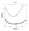
- FIG. 4 is a graph showing the relationship between the separation distance and the defibrillation threshold in Experiment 2.
- FIG. 5 is an explanatory diagram showing the relationship between the energization waveform and the defibrillation threshold in Experiment 3.
- FIG. 6A is a perspective view showing a state of use of the cardiac support net of the second embodiment (a state seen from the front side of the heart), and FIG. 6B is a state of use of the heart support net of the second embodiment (rear side of the heart).
- FIG. FIG. 7A is a perspective view showing a usage state of the cardiac support net of the third embodiment (a state viewed from the front side of the heart), and FIG. 7B is a usage state of the cardiac support net of the third embodiment (rear side of the heart).
- FIG. 6A is a perspective view showing a state of use of the cardiac support net of the second embodiment (a state seen from the front side of the heart)
- FIG. 6B is a state of use of the heart support net of
- FIG. 8A is a perspective view showing a state of use of the cardiac support net of the fourth embodiment (a state seen from the front side of the heart), and FIG. 8B is a state of use of the heart support net of the fourth embodiment (rear side of the heart).
- FIG. 9A is a perspective view showing a usage state of the cardiac support net of the fifth embodiment (a state viewed from the front side of the heart), and FIG. 9B is a usage state of the cardiac support net of the fifth embodiment (rear side of the heart).
- FIG. 9A is a perspective view showing a usage state of the cardiac support net of the fifth embodiment (a state viewed from the front side of the heart)
- FIG. 9B is a usage state of the cardiac support net of the fifth embodiment (rear side of the heart).
- the ICD 1 includes a cardiac support net 11 and a defibrillator body 12.
- the defibrillator body 12 and the heart support net 11 are electrically connected via the first lead 13 and the second lead 14.
- the heart support net 11 includes a housing section 20.
- the accommodating part 20 is configured to be attached to the outside of the ventricle by introducing the heart into the accommodating part 20.
- the accommodating portion 20 includes a first conductive portion 21, a second conductive portion 22 and a non-conductive portion 23. Further, the housing portion 20 is provided with a first opening portion 24 and a second opening portion 25.
- the first conductive portion 21, the second conductive portion 22, and the non-conductive portion 23 are knitted in a net-like shape by, for example, plain knitting.
- the knitting method is not limited to the plain knitting, and may be any knitting method that can secure desired elasticity.
- the cardiac support net 1 does not generate contact pressure when the left ventricular end diastolic pressure (LVEDP) is lower than normal (up to 10 mmHg), and does not cause contact pressure, and a heart failure state (LVEDP 18 mmHg to heart failure Forester classification IV).
- the first conductive portion 21 and the second conductive portion 22 are knitted in a mesh shape with conductive threads.
- Any conductive fiber composed of biocompatible material can be used for the conductive yarn.
- a metal thin wire such as a tungsten thin wire, a stainless steel thin wire, a nickel-titanium alloy (Nitinol) thin wire, or a conductive resin thin wire in which a resin material is used as a base material and a conductive filler such as carbon nanotubes is used as the conductive thread. You may.
- the non-conductive portion 23 is knitted with a non-conductive thread in a net shape.
- Any conductive fiber composed of biocompatible material can be utilized for the non-conductive yarn.
- yarns made by twisting non-absorbent single fibers such as polyester, polytetrafluoroethylene, expanded polytetrafluoroethylene (expanded PTFE, ePTFE), polypropylene, polydifluoroethylene (hexafluoropropylene-vinylidene fluoride) May be used as the non-conductive thread.
- a yarn obtained by twisting absorbent single fibers containing a compound, a mixture, or the like may be used as the non-conductive yarn.
- the conductive thread and the non-conductive thread may be configured by combining two or more kinds of materials. Further, the first conductive portion 21, the second conductive portion 22, and the non-conductive portion 23 may be knitted by combining two or more kinds of yarns of different materials.
- a composite type yarn formed by twisting a conductive thin wire and a non-conductive thin wire has conductivity, and thus is included in the conductive yarn in the present disclosure.
- any thread having performance mechanical strength, chemical strength, stretchability, etc.
- the first opening 24 is used to introduce the heart into the accommodation portion 20.
- the circumference of the first opening 24 may be made of non-conductive yarn over the entire circumference. For example, if the non-conductive yarn is more convenient than the conductive yarn in contacting the first opening 24 around the heart, the first conductive portion 21 is sandwiched between the non-conductive portion 23 and the non-conductive portion 23.
- An additional non-conductive section may be provided, and the first opening 24 may be formed by the additional non-conductive section.
- the second opening 25 is arranged outside the right ventricle of the heart introduced into the accommodation portion 20.
- the shape of the second opening 25 is illustrated as an ellipse for convenience in FIG. 1A and the like, but may actually be a trapezoidal shape having no corners.
- the shape of the second opening 25 is designed to be a range slightly smaller than the reference range corresponding to the outside of the right chamber and a range included inside the reference range. With this, when the cardiac support net 11 is attached to the outside of the ventricle, the portion of the accommodating portion 20 around the second opening 25 is arranged at a position in contact with the peripheral edge of the reference range.
- the 2nd opening part 25 is arrange
- the periphery of the second opening 25 may be made of non-conductive thread over the entire circumference.
- the non-conductive yarn forming the periphery of the second opening 25 may be an absorption yarn. If the periphery of the second opening 25 is made of absorbent yarn, the portion made of absorbent yarn is absorbed after a certain period of time has elapsed since the heart support net 11 was implanted in the heart. Alternatively, the portion made of the non-conductive yarn as described above may not be provided around the second opening 25.
- the heart support net 11 When the heart support net 11 is attached to the heart, the heart is introduced from the apex side into the accommodation section 20 through the first opening 24. Thereby, as shown in FIGS. 2A and 2B, the cardiac support net 11 is attached to the outside of the ventricle. At this time, the second opening 25 is arranged outside the right ventricle as shown in FIG. 2A. By providing the second opening 25 in this manner, the contact pressure between the heart support net 11 and the heart in the diastole is brought into contact with the housing portion 20 and the surface of the ventricle in the range where the second opening 25 is provided. It can be lower than the range.
- the shape and/or size of the second opening 25 need not be adjusted excessively strictly, and may have any shape and/or size as long as the contact pressure applied to the right ventricle side can be reduced. However, if the second opening 25 is excessively small, the contact pressure applied to the right ventricle cannot be reduced sufficiently, and therefore a corresponding size may be required. On the other hand, if the second opening 25 is excessively large, the mounting position of the heart support net 11 may be easily displaced to the left ventricle side, and thus the contact pressure between the outside of the left ventricle and the support net may decrease. ..
- the second opening 25 may be formed in such a range that the outside of the right ventricle can be sufficiently exposed within a range in which the mounting position of the cardiac support net 11 does not excessively shift to the left ventricle side.
- the shape and/or size of the second opening 25 may be set so that the net portion around the second opening 25 just contacts the right ventricle periphery.
- the first conductive portion 21 corresponds to the base side on the outside of the ventricle.
- the second conductive portion 22 corresponds to the apex portion side outside the ventricle.
- the non-conductive portion 23 corresponds to a position on the apex side of the first conductive portion 21 and on the cardiac base side of the second conductive portion 22 on the outside of the ventricle.
- the diameter of the ventricle perpendicular to the direction from the apex to the base that is, the direction along the imaginary axis Z shown by the chain double-dashed line in FIG. 1B) is maximum at a specific position near the base.
- the periphery of the specific position is surrounded by the first conductive portion 21 in a ring shape.
- Defibrillation analysis was performed by computer simulation using a mathematical model of cells. Specifically, the distance between the first conductive portion 21 and the second conductive portion 22 (corresponding to the length L3 of the non-conductive portion 23 along the virtual axis Z shown in FIG. ) Is changed in a plurality of ways, the energization energy is changed in a plurality of ways at each separation distance, defibrillation analysis is performed at each energization timing of 50 times, and the defibrillation success rate is obtained.
- the energization waveform has a shape as shown in FIG. 3A (Bi-Phaseic energization).
- the first conductive portion 21 is at a high potential and the second conductive portion 22 is at a low potential for 5 milliseconds, and then the first conductive portion 21 is at a low potential and the second conductive portion for 3 milliseconds.
- the portion 22 has a high potential.
- the potential gradient between the first conductive portion 21 and the second conductive portion 22 tends to become uneven.
- a specific distance is secured, it is estimated that the potential gradient between the first conducting portion 21 and the second conducting portion 22 will be more uniform.
- it is desirable that a large volume of muscle is included in the flow path of the current that flows between the first conducting portion 21 and the second conducting portion 22.
- the part where the diameter of the ventricle is the maximum is located near the base of the heart, so by installing the first conductive portion 21 up to the vicinity of the maximum diameter of the ventricle, the muscle protrudes from the flow path of the current. It is presumed that it will be possible to energize without the need for effective defibrillation.
- the defibrillation threshold the higher the defibrillation success rate, even if the energizing energy is low.
- the defibrillation threshold value became the minimum value of 0.511 [J].
- the distance L0 is the ventricle height.
- the distance L1 is the height of the first conductive portion 21.
- the distance L2 is the height of the second conductive portion 22.
- the distance L3 is the height of the non-conductive portion 23, and is the above-described distance. In this experiment, the distance L0 was 90 mm.
- the best result could be obtained by setting the distance L1 to about 25% of the distance L0, the distance L2 to about 35% of the distance L0, and the distance L3 to about 40% of the distance L1.
- the energizing energy can be less than 0.7 [J].
- the energizing energy is less than 0.7 [J]
- defibrillation can be performed at a painless level. Therefore, by using the ICD1 illustrated in the first embodiment, defibrillation can be performed without imposing an excessive physical and mental burden on the patient.
- Example 2 The experiment 1 is different from the energization waveform in which the potential is reversed (that is, the first conductive portion 21 has a low potential and the second conductive portion 22 has a high potential for 5 milliseconds, and then the first conductive portion for 3 milliseconds.
- FIG. 4 shows the relationship between the separation distance and the defibrillation threshold value.
- the result of Experiment 2 is shown by a broken line in FIG.
- the result of Experiment 1 is also shown in FIG. 4 by a solid line.
- the defibrillation threshold increases three times or more when the potential change is reversed. Therefore, at least in the case of the electrode arrangement as in the first embodiment, it is important to set the first conductive portion 21 to the high potential first and the second conductive portion 22 to the high potential later in the Bi-Phaseic energization. It is believed that there is.
- the accommodation unit 20 can be attached to the outside of the ventricle by introducing the heart into the accommodation unit 20.
- cardiac remodeling can be suppressed as described above.
- the ICD 1 can be configured by using the first conductive portion 21 and the second conductive portion 22 as electrodes.
- Each of the first conductive portion 21 and the second conductive portion 22 is knitted with conductive yarn in a mesh shape. Therefore, for example, unlike a heart support net in which a metal wire is passed through the mesh of a net knitted with non-conductive yarn, in the heart support net 11, a part or all of the metal wire is pulled out from the mesh of the net. Can be suppressed or avoided. Further, the desired first conductive portion 21 and second conductive portion 22 can be knitted with conductive yarn using a knitting machine. Therefore, after the step of knitting the net with the non-conductive yarn, there is no need to further provide a step of passing a metal wire through the mesh of the net, and the manufacturing process of the heart support net 11 is simplified by that much, Productivity can be improved.
- ICD1 it is possible to suppress energization energy to less than 0.7 [J], for example, to enable defibrillation at a painless level. Therefore, defibrillation can be performed without imposing an excessive physical and mental burden on the patient.
- the heart support net 41 of the second embodiment is different from the first embodiment in that the first conductive portion 21 and the second conductive portion 22 are arranged on the left and right with the heart interposed therebetween. Is different. That is, the first conductive portion 21 corresponds to the left ventricle side outside the ventricle. The second conductive portion 22 corresponds to the right ventricle side outside the ventricle. The non-conductive portion 23 is provided between the first conductive portion 21 and the second conductive portion 22.
- the heart support net 41 including the first conductive portion 21 and the second conductive portion 22 arranged in this way has the same operation and effect as the heart support net 11 of the first embodiment.
- the heart support net 51 of the third embodiment is different from that of the first embodiment in that the first conductive portion 21 and the second conductive portion 22 are arranged in front and rear of the heart. Is different. That is, the first conductive portion 21 corresponds to the front side outside the ventricle. The second conductive portion corresponds to the posterior side outside the ventricle. The non-conductive portion 23 is provided between the first conductive portion 21 and the second conductive portion 22.
- the heart support net 51 including the first conductive portion 21 and the second conductive portion 22 arranged in this way exhibits the same action and effect as the heart support net 11 of the first embodiment.
- the second opening 25 is omitted because of the position where the first conductive portion 21 is provided. That is, whether to provide the second opening 25 is optional. In cases without diastole, left ventricular restraint is unnecessary. Therefore, in this case, by optimizing the size and stretchability of the cardiac support net 51, it is possible to reduce the constraint on the left ventricle and the right ventricle without providing the second opening 25. In addition, if the non-conductive portion 23 is knitted with the absorbent yarn, the restraint of the left chamber and the right chamber can be reduced without providing the second opening 25.
- the heart support net 61 of the fourth embodiment is characterized in that the first conductive portion 21 and the second conductive portion 22 are arranged obliquely above and below the heart, respectively. This is different from the first embodiment.
- the first conductive portion 21 corresponds to the heart base side and the right ventricle side outside the ventricle.
- the second conductive portion 22 corresponds to the apex side and the left ventricle side outside the ventricle.
- the non-conductive portion 23 is provided between the first conductive portion 21 and the second conductive portion 22.
- the heart support net 61 including the first conductive portion 21 and the second conductive portion 22 arranged in this way has the same operation and effect as the heart support net 11 of the first embodiment.
- the second opening 25 is omitted as in the third embodiment.
- the heart support net 71 according to the fifth embodiment is characterized in that the first conductive portion 21 and the second conductive portion 22 are arranged obliquely above and below the heart, respectively. This is different from the first embodiment.
- the first conductive portion 21 corresponds to the cardiac base side and the left ventricle side outside the ventricle.
- the second conductive portion 22 corresponds to the apex side and the right ventricle side outside the ventricle.
- the non-conductive portion 23 is provided between the first conductive portion 21 and the second conductive portion 22.
- the heart support net 71 including the first conductive portion 21 and the second conductive portion 22 arranged in this way exhibits the same operation and effect as the heart support net 11 of the first embodiment.
- the second opening 25 is omitted as in the third embodiment.
- a plurality of types of heart support nets having different sizes may be prepared in advance by assuming the size of the heart.
- a specific shape and size with a tomography apparatus (for example, MRI), or an electrophysiological examination is performed, and based on the image and the result of the electrophysiological examination, the patient has a shape and size suitable for the patient.
- the heart support net which fits snugly into the heart of the human, may be knitted on a computer controlled knitting machine.
- the simulation technique based on the above-described image and the result of the electrophysiological examination is used. , May be optimized for each patient. Further, since the optimal electrode arrangement may differ depending on the patient's case, the cardiac support nets 11, 41, 51, 61 shown in the first to fourth embodiments are properly used according to the patient's case. May be.
- one first conductive portion 21 and one second conductive portion 22 are provided, but in another embodiment, at least one of the first conductive portion 21 and the second conductive portion 22 is provided. It may be divided into two or more.
- each of the above embodiments may be realized by a plurality of components.
- the function realized by a plurality of constituent elements may be realized by one constituent element.
- at least a part of the configuration of each of the above-described embodiments may be added to or replaced with the configuration of the other above-described embodiments.
Abstract
Le filet d'assistance cardiaque selon un aspect de la présente invention est équipé d'une partie de boîtier configurée pour loger un coeur et être montée à l'extérieur d'un ventricule. La partie de boîtier est équipée d'une première partie conductrice, d'une seconde partie conductrice et d'une partie non conductrice La première partie conductrice et la seconde partie conductrice sont tricotées par un fil conducteur sous forme de maillage. La partie non conductrice est tricotée par un fil non conducteur sous forme de maillage.
Priority Applications (5)
| Application Number | Priority Date | Filing Date | Title |
|---|---|---|---|
| PCT/JP2019/007381 WO2020174590A1 (fr) | 2019-02-26 | 2019-02-26 | Filet d'assistance cardiaque et défibrillateur implantable |
| JP2020512903A JP7075606B2 (ja) | 2019-02-26 | 2019-02-26 | 心臓サポートネット及び植込み型除細動器 |
| EP19916564.8A EP3789077B1 (fr) | 2019-02-26 | 2019-02-26 | Filet d'assistance cardiaque et défibrillateur implantable |
| CN201980037008.6A CN112236189A (zh) | 2019-02-26 | 2019-02-26 | 心脏支撑网以及植入型除颤器 |
| US16/972,568 US11229802B2 (en) | 2019-02-26 | 2019-02-26 | Heart support net and implantable cardioverter defibrillator |
Applications Claiming Priority (1)
| Application Number | Priority Date | Filing Date | Title |
|---|---|---|---|
| PCT/JP2019/007381 WO2020174590A1 (fr) | 2019-02-26 | 2019-02-26 | Filet d'assistance cardiaque et défibrillateur implantable |
Publications (1)
| Publication Number | Publication Date |
|---|---|
| WO2020174590A1 true WO2020174590A1 (fr) | 2020-09-03 |
Family
ID=72238402
Family Applications (1)
| Application Number | Title | Priority Date | Filing Date |
|---|---|---|---|
| PCT/JP2019/007381 WO2020174590A1 (fr) | 2019-02-26 | 2019-02-26 | Filet d'assistance cardiaque et défibrillateur implantable |
Country Status (5)
| Country | Link |
|---|---|
| US (1) | US11229802B2 (fr) |
| EP (1) | EP3789077B1 (fr) |
| JP (1) | JP7075606B2 (fr) |
| CN (1) | CN112236189A (fr) |
| WO (1) | WO2020174590A1 (fr) |
Families Citing this family (8)
| Publication number | Priority date | Publication date | Assignee | Title |
|---|---|---|---|---|
| US9554897B2 (en) | 2011-04-28 | 2017-01-31 | Neovasc Tiara Inc. | Methods and apparatus for engaging a valve prosthesis with tissue |
| US9345573B2 (en) | 2012-05-30 | 2016-05-24 | Neovasc Tiara Inc. | Methods and apparatus for loading a prosthesis onto a delivery system |
| EP3672530A4 (fr) | 2017-08-25 | 2021-04-14 | Neovasc Tiara Inc. | Prothèse de valvule mitrale transcathéter à déploiement séquentiel |
| JP7260930B2 (ja) | 2018-11-08 | 2023-04-19 | ニオバスク ティアラ インコーポレイテッド | 経カテーテル僧帽弁人工補綴物の心室展開 |
| EP3946163A4 (fr) | 2019-04-01 | 2022-12-21 | Neovasc Tiara Inc. | Valve prothétique déployable de manière contrôlable |
| EP3972673A4 (fr) | 2019-05-20 | 2023-06-07 | Neovasc Tiara Inc. | Dispositif d'introduction avec mécanisme d'hémostase |
| WO2020257643A1 (fr) | 2019-06-20 | 2020-12-24 | Neovasc Tiara Inc. | Valve mitrale prothétique à profil bas |
| JP6815683B1 (ja) * | 2020-02-27 | 2021-01-20 | 株式会社iCorNet研究所 | 電極付心臓ネット |
Citations (5)
| Publication number | Priority date | Publication date | Assignee | Title |
|---|---|---|---|---|
| JPH05337204A (ja) * | 1992-01-30 | 1993-12-21 | Cardiac Pacemakers Inc | 長持続時間の波形を発生する細動除去波形発生器 |
| US6169922B1 (en) | 1998-11-18 | 2001-01-02 | Acorn Cardiovascular, Inc. | Defibrillating cardiac jacket with interwoven electrode grids |
| JP2005537871A (ja) * | 2002-09-05 | 2005-12-15 | パラコー メディカル インコーポレイテッド | 心臓ハーネス |
| JP2011056182A (ja) | 2009-09-14 | 2011-03-24 | Olympus Corp | 除細動電極組立体、除細動電極部分組立体、および植込み型除細動システム |
| JP2017025418A (ja) * | 2015-07-15 | 2017-02-02 | グンゼ株式会社 | 導電編地 |
Family Cites Families (24)
| Publication number | Priority date | Publication date | Assignee | Title |
|---|---|---|---|---|
| US4030509A (en) * | 1975-09-30 | 1977-06-21 | Mieczyslaw Mirowski | Implantable electrodes for accomplishing ventricular defibrillation and pacing and method of electrode implantation and utilization |
| US4821723A (en) * | 1987-02-27 | 1989-04-18 | Intermedics Inc. | Biphasic waveforms for defibrillation |
| US5702343A (en) | 1996-10-02 | 1997-12-30 | Acorn Medical, Inc. | Cardiac reinforcement device |
| US6123662A (en) | 1998-07-13 | 2000-09-26 | Acorn Cardiovascular, Inc. | Cardiac disease treatment and device |
| US6076013A (en) | 1999-01-14 | 2000-06-13 | Brennan; Edward F. | Apparatus and methods for treating congestive heart failure |
| AU6951500A (en) * | 1999-06-07 | 2000-12-28 | Johns Hopkins University, The | Cardiac shock electrode system and corresponding implantable defibrillator system |
| US6293906B1 (en) | 2000-01-14 | 2001-09-25 | Acorn Cardiovascular, Inc. | Delivery of cardiac constraint jacket |
| CA2402504A1 (fr) | 2000-03-10 | 2001-09-20 | Paracor Surgical, Inc. | Harnais cardiaque extensible permettant de traiter l'insuffisance cardiaque congestive |
| US6951534B2 (en) | 2000-06-13 | 2005-10-04 | Acorn Cardiovascular, Inc. | Cardiac support device |
| US7181272B2 (en) | 2002-04-22 | 2007-02-20 | Medtronic, Inc. | Cardiac restraint with electrode attachment sites |
| US20050283042A1 (en) | 2003-03-28 | 2005-12-22 | Steve Meyer | Cardiac harness having radiopaque coating and method of use |
| US20040249242A1 (en) | 2003-03-28 | 2004-12-09 | Lilip Lau | Multi-panel cardiac harness |
| US7155295B2 (en) | 2003-11-07 | 2006-12-26 | Paracor Medical, Inc. | Cardiac harness for treating congestive heart failure and for defibrillating and/or pacing/sensing |
| US20070197859A1 (en) | 2003-11-07 | 2007-08-23 | Paracor Medical, Inc. | Cardiac harness having diagnostic sensors and method of use |
| JP4261422B2 (ja) | 2004-05-21 | 2009-04-30 | 東洋紡績株式会社 | 心臓装着用弾性ネット |
| US7587247B2 (en) | 2005-08-01 | 2009-09-08 | Paracor Medical, Inc. | Cardiac harness having an optimal impedance range |
| US7640065B1 (en) * | 2006-03-17 | 2009-12-29 | Pacesetter, Inc. | Cardiac constraint/therapeutic stimulation device |
| JP2011056180A (ja) | 2009-09-14 | 2011-03-24 | Olympus Corp | 治療用電極体及び除細動器 |
| JP5337204B2 (ja) | 2011-06-23 | 2013-11-06 | 美佐緒 片井 | 測量用ターゲット支持具 |
| JP6084775B2 (ja) * | 2012-03-09 | 2017-02-22 | 学校法人金沢医科大学 | 心臓矯正ネット |
| US9566443B2 (en) | 2013-11-26 | 2017-02-14 | Corquest Medical, Inc. | System for treating heart valve malfunction including mitral regurgitation |
| KR101741187B1 (ko) * | 2014-11-11 | 2017-05-30 | 서울대학교산학협력단 | 심장의 재동기화 치료를 위한 그물망 전극 및 이의 제조 방법 |
| WO2017010234A1 (fr) * | 2015-07-15 | 2017-01-19 | グンゼ株式会社 | Tricot étirable conducteur de l'électricité doté d'une propriété invariable de résistance électrique |
| JP6583722B2 (ja) * | 2015-08-12 | 2019-10-02 | 株式会社iCorNet研究所 | 心臓サポーターの設計方法、心臓サポーターの製造方法 |
-
2019
- 2019-02-26 CN CN201980037008.6A patent/CN112236189A/zh active Pending
- 2019-02-26 JP JP2020512903A patent/JP7075606B2/ja active Active
- 2019-02-26 EP EP19916564.8A patent/EP3789077B1/fr active Active
- 2019-02-26 WO PCT/JP2019/007381 patent/WO2020174590A1/fr unknown
- 2019-02-26 US US16/972,568 patent/US11229802B2/en active Active
Patent Citations (5)
| Publication number | Priority date | Publication date | Assignee | Title |
|---|---|---|---|---|
| JPH05337204A (ja) * | 1992-01-30 | 1993-12-21 | Cardiac Pacemakers Inc | 長持続時間の波形を発生する細動除去波形発生器 |
| US6169922B1 (en) | 1998-11-18 | 2001-01-02 | Acorn Cardiovascular, Inc. | Defibrillating cardiac jacket with interwoven electrode grids |
| JP2005537871A (ja) * | 2002-09-05 | 2005-12-15 | パラコー メディカル インコーポレイテッド | 心臓ハーネス |
| JP2011056182A (ja) | 2009-09-14 | 2011-03-24 | Olympus Corp | 除細動電極組立体、除細動電極部分組立体、および植込み型除細動システム |
| JP2017025418A (ja) * | 2015-07-15 | 2017-02-02 | グンゼ株式会社 | 導電編地 |
Non-Patent Citations (1)
| Title |
|---|
| See also references of EP3789077A4 |
Also Published As
| Publication number | Publication date |
|---|---|
| US11229802B2 (en) | 2022-01-25 |
| EP3789077A1 (fr) | 2021-03-10 |
| EP3789077B1 (fr) | 2022-08-31 |
| JP7075606B2 (ja) | 2022-05-26 |
| US20210236833A1 (en) | 2021-08-05 |
| CN112236189A (zh) | 2021-01-15 |
| JPWO2020174590A1 (fr) | 2020-09-03 |
| EP3789077A4 (fr) | 2021-07-07 |
Similar Documents
| Publication | Publication Date | Title |
|---|---|---|
| WO2020174590A1 (fr) | Filet d'assistance cardiaque et défibrillateur implantable | |
| US6633780B1 (en) | Cardiac shock electrode system and corresponding implantable defibrillator system | |
| US5385574A (en) | Implantable intravenous cardiac stimulation system with pulse generator housing serving as optional additional electrode | |
| EP0740563B1 (fr) | Fil electrique medical temporaire | |
| US5085218A (en) | Bipolar myocardial positive fixation lead with improved sensing capability | |
| CN111405925A (zh) | 用于希氏束起搏的系统 | |
| US20060142804A1 (en) | Implantable intravenous cardiac stimulation system with pulse generator housing serving as optional additional electrode | |
| JP2007533373A (ja) | 完全抑止型二腔ペーシングモード | |
| JP2004536678A5 (fr) | ||
| US9884184B2 (en) | Wire hook coupling for lead extension and extraction | |
| CN108310652A (zh) | 心脏植入装置及起搏系统 | |
| JPWO2020174590A5 (fr) | ||
| JP2011506038A (ja) | 選択的に起動される検出向上策を有する抗頻脈性不整脈システム | |
| JP2009502418A (ja) | 最適なインピーダンス範囲を有する心臓ハーネス | |
| EP2863989B1 (fr) | Contact d'adaptateur de dispositif implantable | |
| Bunch et al. | Pacing and defibrillation: clinically relevant basics for practice | |
| US6639153B2 (en) | Patient lead wire detangler | |
| US7596409B2 (en) | Cardiac shock electrode system and corresponding implantable defibrillator system | |
| JP6815683B1 (ja) | 電極付心臓ネット | |
| US7740980B2 (en) | Electrode including a multi-region current collector | |
| CN110152191A (zh) | 无导线起搏器 | |
| EP3492140B1 (fr) | Stimulation anti-tachycardie pour dispositifs médicaux implantables de faible puissance | |
| JP2016002207A (ja) | 除細動システム | |
| JP2011056198A (ja) | 除細動電極 | |
| JP5393368B2 (ja) | 電極体 |
Legal Events
| Date | Code | Title | Description |
|---|---|---|---|
| ENP | Entry into the national phase |
Ref document number: 2020512903 Country of ref document: JP Kind code of ref document: A |
|
| 121 | Ep: the epo has been informed by wipo that ep was designated in this application |
Ref document number: 19916564 Country of ref document: EP Kind code of ref document: A1 |
|
| ENP | Entry into the national phase |
Ref document number: 2019916564 Country of ref document: EP Effective date: 20201202 |
|
| NENP | Non-entry into the national phase |
Ref country code: DE |