WO2020174590A1 - Cardiac support net and implantable defibrillator - Google Patents
Cardiac support net and implantable defibrillator Download PDFInfo
- Publication number
- WO2020174590A1 WO2020174590A1 PCT/JP2019/007381 JP2019007381W WO2020174590A1 WO 2020174590 A1 WO2020174590 A1 WO 2020174590A1 JP 2019007381 W JP2019007381 W JP 2019007381W WO 2020174590 A1 WO2020174590 A1 WO 2020174590A1
- Authority
- WO
- WIPO (PCT)
- Prior art keywords
- conductive portion
- support net
- ventricle
- conductive
- heart
- Prior art date
Links
Images


Classifications
-
- A—HUMAN NECESSITIES
- A61—MEDICAL OR VETERINARY SCIENCE; HYGIENE
- A61N—ELECTROTHERAPY; MAGNETOTHERAPY; RADIATION THERAPY; ULTRASOUND THERAPY
- A61N1/00—Electrotherapy; Circuits therefor
- A61N1/18—Applying electric currents by contact electrodes
- A61N1/32—Applying electric currents by contact electrodes alternating or intermittent currents
- A61N1/38—Applying electric currents by contact electrodes alternating or intermittent currents for producing shock effects
- A61N1/39—Heart defibrillators
- A61N1/3956—Implantable devices for applying electric shocks to the heart, e.g. for cardioversion
-
- A—HUMAN NECESSITIES
- A61—MEDICAL OR VETERINARY SCIENCE; HYGIENE
- A61F—FILTERS IMPLANTABLE INTO BLOOD VESSELS; PROSTHESES; DEVICES PROVIDING PATENCY TO, OR PREVENTING COLLAPSING OF, TUBULAR STRUCTURES OF THE BODY, e.g. STENTS; ORTHOPAEDIC, NURSING OR CONTRACEPTIVE DEVICES; FOMENTATION; TREATMENT OR PROTECTION OF EYES OR EARS; BANDAGES, DRESSINGS OR ABSORBENT PADS; FIRST-AID KITS
- A61F2/00—Filters implantable into blood vessels; Prostheses, i.e. artificial substitutes or replacements for parts of the body; Appliances for connecting them with the body; Devices providing patency to, or preventing collapsing of, tubular structures of the body, e.g. stents
- A61F2/02—Prostheses implantable into the body
- A61F2/24—Heart valves ; Vascular valves, e.g. venous valves; Heart implants, e.g. passive devices for improving the function of the native valve or the heart muscle; Transmyocardial revascularisation [TMR] devices; Valves implantable in the body
- A61F2/2478—Passive devices for improving the function of the heart muscle, i.e. devices for reshaping the external surface of the heart, e.g. bags, strips or bands
- A61F2/2481—Devices outside the heart wall, e.g. bags, strips or bands
-
- A—HUMAN NECESSITIES
- A61—MEDICAL OR VETERINARY SCIENCE; HYGIENE
- A61N—ELECTROTHERAPY; MAGNETOTHERAPY; RADIATION THERAPY; ULTRASOUND THERAPY
- A61N1/00—Electrotherapy; Circuits therefor
- A61N1/02—Details
- A61N1/04—Electrodes
- A61N1/05—Electrodes for implantation or insertion into the body, e.g. heart electrode
- A61N1/0587—Epicardial electrode systems; Endocardial electrodes piercing the pericardium
- A61N1/0597—Surface area electrodes, e.g. cardiac harness
-
- A—HUMAN NECESSITIES
- A61—MEDICAL OR VETERINARY SCIENCE; HYGIENE
- A61F—FILTERS IMPLANTABLE INTO BLOOD VESSELS; PROSTHESES; DEVICES PROVIDING PATENCY TO, OR PREVENTING COLLAPSING OF, TUBULAR STRUCTURES OF THE BODY, e.g. STENTS; ORTHOPAEDIC, NURSING OR CONTRACEPTIVE DEVICES; FOMENTATION; TREATMENT OR PROTECTION OF EYES OR EARS; BANDAGES, DRESSINGS OR ABSORBENT PADS; FIRST-AID KITS
- A61F2250/00—Special features of prostheses classified in groups A61F2/00 - A61F2/26 or A61F2/82 or A61F9/00 or A61F11/00 or subgroups thereof
- A61F2250/0014—Special features of prostheses classified in groups A61F2/00 - A61F2/26 or A61F2/82 or A61F9/00 or A61F11/00 or subgroups thereof having different values of a given property or geometrical feature, e.g. mechanical property or material property, at different locations within the same prosthesis
- A61F2250/0043—Special features of prostheses classified in groups A61F2/00 - A61F2/26 or A61F2/82 or A61F9/00 or A61F11/00 or subgroups thereof having different values of a given property or geometrical feature, e.g. mechanical property or material property, at different locations within the same prosthesis differing in electric properties, e.g. in electrical conductivity, in galvanic properties
Definitions
- the present disclosure relates to a cardiac support net and an implantable defibrillator.
- Patent Document 1 An implantable defibrillator (hereinafter, also referred to as ICD) disclosed in Patent Document 1 below is a medical device that stops a fatal arrhythmia such as ventricular tachycardia or ventricular fibrillation and restores the function of the heart. ..
- Patent Document 2 discloses a technique in which a linear electrode conductor is attached to a heart support net attached to the outside of the heart to apply a defibrillation shock to the heart.
- the linear electrode conductors are zigzag with respect to the mesh of the cardiac support net. Examples of linear electrode conductors include titanium wires and platinum-coated stainless steel.
- the thin metal wire serving as the electrode conductor is passed through the mesh of the heart support net. For this reason, the work of passing the thin metal wire through the mesh takes time, and the productivity of the cardiac support net may be reduced. For example, if the metal wire is pulled and part or all of the metal wire is pulled out from the mesh, it is difficult to return the metal wire to the original position. Therefore, if such a situation is reached, the cardiac support net must be discarded and a new cardiac support net must be used. In order to prevent such a situation, the heart support net must be handled carefully and carefully so as not to pull the metal wire, which may reduce workability during use.
- a cardiac support net includes a housing configured to house a heart and be attached to the outside of a ventricle.
- the accommodation section includes a first conductive section, a second conductive section, and a non-conductive section.
- the first conductive portion and the second conductive portion are knitted with conductive threads in a net shape.
- the non-conductive portion is knitted with a non-conductive thread in a net shape.
- the accommodation unit can be attached to the outside of the ventricle by introducing the heart into the accommodation unit.
- the cardiac support net does not produce pressure when the left ventricular end diastolic pressure (LVEDP) is below normal ( ⁇ 10 mmHg), but does not cause contact pressure, and in the heart failure state (LVEDP 18 mmHg ⁇ heart failure Forester classification IV), it is 5 mmHg ⁇ . It may be configured so as to generate pressure on the surface of the left ventricle and to generate pressure on the LVEDP of 10 mmHg at 30 mmHg. According to this structure, the expansion of the heart is not hindered when the LVEDP is low, and the excessive expansion of the heart is prevented or suppressed when the LVEDP is high, thereby exhibiting the effect of preventing or suppressing the cardiac remodeling.
- the ICD can be configured by using the first conductive part and the second conductive part as electrodes.
- each of the first conductive portion and the second conductive portion is knitted with a conductive thread in a net shape. Therefore, in the cardiac support net of the present disclosure, unlike the cardiac support net in which the metal wire is passed through the mesh of the net formed by the non-conductive yarn, a part or all of the metal wire is pulled out from the mesh of the net. It can be suppressed or avoided.
- the first conductive portion and the second conductive portion can be knitted with conductive yarn using a knitting machine. Therefore, after the step of knitting the net with the non-conductive yarn, there is no need to provide a step of passing a metal wire through the mesh of the net, which simplifies the manufacturing process of the cardiac support net and increases the productivity of the cardiac support net. Can be improved.
- the conductive thread may be any conductive fiber composed of biocompatible material.
- the conductive thread is, for example, a thin metal wire such as a thin tungsten wire, a thin stainless steel wire, or a nickel-titanium alloy (Nitinol) thin wire, or a conductive resin thin wire in which a conductive filler such as carbon nanotubes is filled with a resin material as a base material. May be.
- the non-conductive thread may be any conductive fiber composed of biocompatible material.
- the non-conductive yarn is, for example, a non-absorbent single fiber such as polyester, polytetrafluoroethylene, expanded polytetrafluoroethylene (expanded PTFE, ePTFE), polypropylene, polydifluoroethylene (hexafluoropropylene-vinylidene fluoride), etc. It may be a twisted yarn.
- the non-conductive yarn is polyglactin, polyglycolic acid, polyethylene glycol, polydioxanone, polylactic acid, polylactide, polyglycolide, polycaprolactone, polyanhydride, polyamide, polyurethane, polyesteramide, polyorthoester, polydioxanone, polyacetal, Polyketal, polycarbonate, polyorthoester, polyphosphazene, polyhydroxybutyrate, polyhydroxyvalerate, polyalkylene oxalate, polyalkylene succinate, poly(methyl vinyl ether), poly(maleic anhydride), poly(amino acid), and It may be a yarn in which absorbent single fibers containing these copolymers, compounds or mixtures are twisted together.
- the non-conductive yarn may be an absorbent yarn.
- the conductive thread and/or the non-conductive thread may be configured by combining two or more kinds of materials.
- the first conductive portion, the second conductive portion, and/or the non-conductive portion may be knitted by combining two or more kinds of threads made of different materials.
- the non-conductive section may be provided between the first conductive section and the second conductive section.
- the first conductive portion may correspond to the base side of the heart outside the ventricle.
- the second conductive part may correspond to the apex side outside the ventricle.
- the distance between the first conductive portion and the second conductive portion may be set in any manner, but it depends on the size of the heart, but the heart has a standard size (for example, the height of the heart is 90 mm). In the above, it may be 14 mm or more and 50 mm or less.
- the first conductive portion may correspond to the left ventricle side outside the ventricle.
- the second conductive portion may correspond to the right ventricle side outside the ventricle.
- the first conductive portion may correspond to the front side outside the ventricle.
- the second conductive portion may correspond to the posterior side outside the ventricle.
- the first conductive portion may correspond to the base side and the left ventricle side outside the ventricle.
- the second conductive portion may correspond to the apex side and the right ventricle side outside the ventricle.
- the first conductive portion may correspond to the cardiac base side and the right ventricle side outside the ventricle.
- the second conductive portion may correspond to the apex side and the left ventricle side outside the ventricle.
- An implantable defibrillator includes the above-described cardiac support net and a defibrillator body.
- the defibrillator body is connected to the cardiac support net.
- the defibrillator body sets the potential of the first conductive portion corresponding to the cardiac base side higher than the potential of the second conductive portion corresponding to the apex side, and then sets the potential of the second conductive portion to the first potential. You may operate so that it may become higher than the electric potential of a conductive part.
- FIG. 1A is an explanatory diagram showing a schematic configuration of an implantable defibrillator
- FIG. 1B is an explanatory diagram showing a schematic configuration of a cardiac support net
- FIG. 2A is a perspective view showing a usage state of the cardiac support net of the first embodiment (a state viewed from the front side of the heart)
- FIG. 2B is a usage state of the cardiac support net of the first embodiment (rear side of the heart).
- FIG. FIG. 3A is an explanatory diagram showing the energization waveform in Experiment 1
- FIG. 3B is a graph showing the relationship between the separation distance and the defibrillation threshold in Experiment 1.
- FIG. 1A is an explanatory diagram showing a schematic configuration of an implantable defibrillator
- FIG. 1B is an explanatory diagram showing a schematic configuration of a cardiac support net.
- FIG. 2A is a perspective view showing a usage state of the cardiac support net of the first embodiment (a state viewed
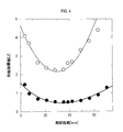
- FIG. 4 is a graph showing the relationship between the separation distance and the defibrillation threshold in Experiment 2.
- FIG. 5 is an explanatory diagram showing the relationship between the energization waveform and the defibrillation threshold in Experiment 3.
- FIG. 6A is a perspective view showing a state of use of the cardiac support net of the second embodiment (a state seen from the front side of the heart), and FIG. 6B is a state of use of the heart support net of the second embodiment (rear side of the heart).
- FIG. FIG. 7A is a perspective view showing a usage state of the cardiac support net of the third embodiment (a state viewed from the front side of the heart), and FIG. 7B is a usage state of the cardiac support net of the third embodiment (rear side of the heart).
- FIG. 6A is a perspective view showing a state of use of the cardiac support net of the second embodiment (a state seen from the front side of the heart)
- FIG. 6B is a state of use of the heart support net of
- FIG. 8A is a perspective view showing a state of use of the cardiac support net of the fourth embodiment (a state seen from the front side of the heart), and FIG. 8B is a state of use of the heart support net of the fourth embodiment (rear side of the heart).
- FIG. 9A is a perspective view showing a usage state of the cardiac support net of the fifth embodiment (a state viewed from the front side of the heart), and FIG. 9B is a usage state of the cardiac support net of the fifth embodiment (rear side of the heart).
- FIG. 9A is a perspective view showing a usage state of the cardiac support net of the fifth embodiment (a state viewed from the front side of the heart)
- FIG. 9B is a usage state of the cardiac support net of the fifth embodiment (rear side of the heart).
- the ICD 1 includes a cardiac support net 11 and a defibrillator body 12.
- the defibrillator body 12 and the heart support net 11 are electrically connected via the first lead 13 and the second lead 14.
- the heart support net 11 includes a housing section 20.
- the accommodating part 20 is configured to be attached to the outside of the ventricle by introducing the heart into the accommodating part 20.
- the accommodating portion 20 includes a first conductive portion 21, a second conductive portion 22 and a non-conductive portion 23. Further, the housing portion 20 is provided with a first opening portion 24 and a second opening portion 25.
- the first conductive portion 21, the second conductive portion 22, and the non-conductive portion 23 are knitted in a net-like shape by, for example, plain knitting.
- the knitting method is not limited to the plain knitting, and may be any knitting method that can secure desired elasticity.
- the cardiac support net 1 does not generate contact pressure when the left ventricular end diastolic pressure (LVEDP) is lower than normal (up to 10 mmHg), and does not cause contact pressure, and a heart failure state (LVEDP 18 mmHg to heart failure Forester classification IV).
- the first conductive portion 21 and the second conductive portion 22 are knitted in a mesh shape with conductive threads.
- Any conductive fiber composed of biocompatible material can be used for the conductive yarn.
- a metal thin wire such as a tungsten thin wire, a stainless steel thin wire, a nickel-titanium alloy (Nitinol) thin wire, or a conductive resin thin wire in which a resin material is used as a base material and a conductive filler such as carbon nanotubes is used as the conductive thread. You may.
- the non-conductive portion 23 is knitted with a non-conductive thread in a net shape.
- Any conductive fiber composed of biocompatible material can be utilized for the non-conductive yarn.
- yarns made by twisting non-absorbent single fibers such as polyester, polytetrafluoroethylene, expanded polytetrafluoroethylene (expanded PTFE, ePTFE), polypropylene, polydifluoroethylene (hexafluoropropylene-vinylidene fluoride) May be used as the non-conductive thread.
- a yarn obtained by twisting absorbent single fibers containing a compound, a mixture, or the like may be used as the non-conductive yarn.
- the conductive thread and the non-conductive thread may be configured by combining two or more kinds of materials. Further, the first conductive portion 21, the second conductive portion 22, and the non-conductive portion 23 may be knitted by combining two or more kinds of yarns of different materials.
- a composite type yarn formed by twisting a conductive thin wire and a non-conductive thin wire has conductivity, and thus is included in the conductive yarn in the present disclosure.
- any thread having performance mechanical strength, chemical strength, stretchability, etc.
- the first opening 24 is used to introduce the heart into the accommodation portion 20.
- the circumference of the first opening 24 may be made of non-conductive yarn over the entire circumference. For example, if the non-conductive yarn is more convenient than the conductive yarn in contacting the first opening 24 around the heart, the first conductive portion 21 is sandwiched between the non-conductive portion 23 and the non-conductive portion 23.
- An additional non-conductive section may be provided, and the first opening 24 may be formed by the additional non-conductive section.
- the second opening 25 is arranged outside the right ventricle of the heart introduced into the accommodation portion 20.
- the shape of the second opening 25 is illustrated as an ellipse for convenience in FIG. 1A and the like, but may actually be a trapezoidal shape having no corners.
- the shape of the second opening 25 is designed to be a range slightly smaller than the reference range corresponding to the outside of the right chamber and a range included inside the reference range. With this, when the cardiac support net 11 is attached to the outside of the ventricle, the portion of the accommodating portion 20 around the second opening 25 is arranged at a position in contact with the peripheral edge of the reference range.
- the 2nd opening part 25 is arrange
- the periphery of the second opening 25 may be made of non-conductive thread over the entire circumference.
- the non-conductive yarn forming the periphery of the second opening 25 may be an absorption yarn. If the periphery of the second opening 25 is made of absorbent yarn, the portion made of absorbent yarn is absorbed after a certain period of time has elapsed since the heart support net 11 was implanted in the heart. Alternatively, the portion made of the non-conductive yarn as described above may not be provided around the second opening 25.
- the heart support net 11 When the heart support net 11 is attached to the heart, the heart is introduced from the apex side into the accommodation section 20 through the first opening 24. Thereby, as shown in FIGS. 2A and 2B, the cardiac support net 11 is attached to the outside of the ventricle. At this time, the second opening 25 is arranged outside the right ventricle as shown in FIG. 2A. By providing the second opening 25 in this manner, the contact pressure between the heart support net 11 and the heart in the diastole is brought into contact with the housing portion 20 and the surface of the ventricle in the range where the second opening 25 is provided. It can be lower than the range.
- the shape and/or size of the second opening 25 need not be adjusted excessively strictly, and may have any shape and/or size as long as the contact pressure applied to the right ventricle side can be reduced. However, if the second opening 25 is excessively small, the contact pressure applied to the right ventricle cannot be reduced sufficiently, and therefore a corresponding size may be required. On the other hand, if the second opening 25 is excessively large, the mounting position of the heart support net 11 may be easily displaced to the left ventricle side, and thus the contact pressure between the outside of the left ventricle and the support net may decrease. ..
- the second opening 25 may be formed in such a range that the outside of the right ventricle can be sufficiently exposed within a range in which the mounting position of the cardiac support net 11 does not excessively shift to the left ventricle side.
- the shape and/or size of the second opening 25 may be set so that the net portion around the second opening 25 just contacts the right ventricle periphery.
- the first conductive portion 21 corresponds to the base side on the outside of the ventricle.
- the second conductive portion 22 corresponds to the apex portion side outside the ventricle.
- the non-conductive portion 23 corresponds to a position on the apex side of the first conductive portion 21 and on the cardiac base side of the second conductive portion 22 on the outside of the ventricle.
- the diameter of the ventricle perpendicular to the direction from the apex to the base that is, the direction along the imaginary axis Z shown by the chain double-dashed line in FIG. 1B) is maximum at a specific position near the base.
- the periphery of the specific position is surrounded by the first conductive portion 21 in a ring shape.
- Defibrillation analysis was performed by computer simulation using a mathematical model of cells. Specifically, the distance between the first conductive portion 21 and the second conductive portion 22 (corresponding to the length L3 of the non-conductive portion 23 along the virtual axis Z shown in FIG. ) Is changed in a plurality of ways, the energization energy is changed in a plurality of ways at each separation distance, defibrillation analysis is performed at each energization timing of 50 times, and the defibrillation success rate is obtained.
- the energization waveform has a shape as shown in FIG. 3A (Bi-Phaseic energization).
- the first conductive portion 21 is at a high potential and the second conductive portion 22 is at a low potential for 5 milliseconds, and then the first conductive portion 21 is at a low potential and the second conductive portion for 3 milliseconds.
- the portion 22 has a high potential.
- the potential gradient between the first conductive portion 21 and the second conductive portion 22 tends to become uneven.
- a specific distance is secured, it is estimated that the potential gradient between the first conducting portion 21 and the second conducting portion 22 will be more uniform.
- it is desirable that a large volume of muscle is included in the flow path of the current that flows between the first conducting portion 21 and the second conducting portion 22.
- the part where the diameter of the ventricle is the maximum is located near the base of the heart, so by installing the first conductive portion 21 up to the vicinity of the maximum diameter of the ventricle, the muscle protrudes from the flow path of the current. It is presumed that it will be possible to energize without the need for effective defibrillation.
- the defibrillation threshold the higher the defibrillation success rate, even if the energizing energy is low.
- the defibrillation threshold value became the minimum value of 0.511 [J].
- the distance L0 is the ventricle height.
- the distance L1 is the height of the first conductive portion 21.
- the distance L2 is the height of the second conductive portion 22.
- the distance L3 is the height of the non-conductive portion 23, and is the above-described distance. In this experiment, the distance L0 was 90 mm.
- the best result could be obtained by setting the distance L1 to about 25% of the distance L0, the distance L2 to about 35% of the distance L0, and the distance L3 to about 40% of the distance L1.
- the energizing energy can be less than 0.7 [J].
- the energizing energy is less than 0.7 [J]
- defibrillation can be performed at a painless level. Therefore, by using the ICD1 illustrated in the first embodiment, defibrillation can be performed without imposing an excessive physical and mental burden on the patient.
- Example 2 The experiment 1 is different from the energization waveform in which the potential is reversed (that is, the first conductive portion 21 has a low potential and the second conductive portion 22 has a high potential for 5 milliseconds, and then the first conductive portion for 3 milliseconds.
- FIG. 4 shows the relationship between the separation distance and the defibrillation threshold value.
- the result of Experiment 2 is shown by a broken line in FIG.
- the result of Experiment 1 is also shown in FIG. 4 by a solid line.
- the defibrillation threshold increases three times or more when the potential change is reversed. Therefore, at least in the case of the electrode arrangement as in the first embodiment, it is important to set the first conductive portion 21 to the high potential first and the second conductive portion 22 to the high potential later in the Bi-Phaseic energization. It is believed that there is.
- the accommodation unit 20 can be attached to the outside of the ventricle by introducing the heart into the accommodation unit 20.
- cardiac remodeling can be suppressed as described above.
- the ICD 1 can be configured by using the first conductive portion 21 and the second conductive portion 22 as electrodes.
- Each of the first conductive portion 21 and the second conductive portion 22 is knitted with conductive yarn in a mesh shape. Therefore, for example, unlike a heart support net in which a metal wire is passed through the mesh of a net knitted with non-conductive yarn, in the heart support net 11, a part or all of the metal wire is pulled out from the mesh of the net. Can be suppressed or avoided. Further, the desired first conductive portion 21 and second conductive portion 22 can be knitted with conductive yarn using a knitting machine. Therefore, after the step of knitting the net with the non-conductive yarn, there is no need to further provide a step of passing a metal wire through the mesh of the net, and the manufacturing process of the heart support net 11 is simplified by that much, Productivity can be improved.
- ICD1 it is possible to suppress energization energy to less than 0.7 [J], for example, to enable defibrillation at a painless level. Therefore, defibrillation can be performed without imposing an excessive physical and mental burden on the patient.
- the heart support net 41 of the second embodiment is different from the first embodiment in that the first conductive portion 21 and the second conductive portion 22 are arranged on the left and right with the heart interposed therebetween. Is different. That is, the first conductive portion 21 corresponds to the left ventricle side outside the ventricle. The second conductive portion 22 corresponds to the right ventricle side outside the ventricle. The non-conductive portion 23 is provided between the first conductive portion 21 and the second conductive portion 22.
- the heart support net 41 including the first conductive portion 21 and the second conductive portion 22 arranged in this way has the same operation and effect as the heart support net 11 of the first embodiment.
- the heart support net 51 of the third embodiment is different from that of the first embodiment in that the first conductive portion 21 and the second conductive portion 22 are arranged in front and rear of the heart. Is different. That is, the first conductive portion 21 corresponds to the front side outside the ventricle. The second conductive portion corresponds to the posterior side outside the ventricle. The non-conductive portion 23 is provided between the first conductive portion 21 and the second conductive portion 22.
- the heart support net 51 including the first conductive portion 21 and the second conductive portion 22 arranged in this way exhibits the same action and effect as the heart support net 11 of the first embodiment.
- the second opening 25 is omitted because of the position where the first conductive portion 21 is provided. That is, whether to provide the second opening 25 is optional. In cases without diastole, left ventricular restraint is unnecessary. Therefore, in this case, by optimizing the size and stretchability of the cardiac support net 51, it is possible to reduce the constraint on the left ventricle and the right ventricle without providing the second opening 25. In addition, if the non-conductive portion 23 is knitted with the absorbent yarn, the restraint of the left chamber and the right chamber can be reduced without providing the second opening 25.
- the heart support net 61 of the fourth embodiment is characterized in that the first conductive portion 21 and the second conductive portion 22 are arranged obliquely above and below the heart, respectively. This is different from the first embodiment.
- the first conductive portion 21 corresponds to the heart base side and the right ventricle side outside the ventricle.
- the second conductive portion 22 corresponds to the apex side and the left ventricle side outside the ventricle.
- the non-conductive portion 23 is provided between the first conductive portion 21 and the second conductive portion 22.
- the heart support net 61 including the first conductive portion 21 and the second conductive portion 22 arranged in this way has the same operation and effect as the heart support net 11 of the first embodiment.
- the second opening 25 is omitted as in the third embodiment.
- the heart support net 71 according to the fifth embodiment is characterized in that the first conductive portion 21 and the second conductive portion 22 are arranged obliquely above and below the heart, respectively. This is different from the first embodiment.
- the first conductive portion 21 corresponds to the cardiac base side and the left ventricle side outside the ventricle.
- the second conductive portion 22 corresponds to the apex side and the right ventricle side outside the ventricle.
- the non-conductive portion 23 is provided between the first conductive portion 21 and the second conductive portion 22.
- the heart support net 71 including the first conductive portion 21 and the second conductive portion 22 arranged in this way exhibits the same operation and effect as the heart support net 11 of the first embodiment.
- the second opening 25 is omitted as in the third embodiment.
- a plurality of types of heart support nets having different sizes may be prepared in advance by assuming the size of the heart.
- a specific shape and size with a tomography apparatus (for example, MRI), or an electrophysiological examination is performed, and based on the image and the result of the electrophysiological examination, the patient has a shape and size suitable for the patient.
- the heart support net which fits snugly into the heart of the human, may be knitted on a computer controlled knitting machine.
- the simulation technique based on the above-described image and the result of the electrophysiological examination is used. , May be optimized for each patient. Further, since the optimal electrode arrangement may differ depending on the patient's case, the cardiac support nets 11, 41, 51, 61 shown in the first to fourth embodiments are properly used according to the patient's case. May be.
- one first conductive portion 21 and one second conductive portion 22 are provided, but in another embodiment, at least one of the first conductive portion 21 and the second conductive portion 22 is provided. It may be divided into two or more.
- each of the above embodiments may be realized by a plurality of components.
- the function realized by a plurality of constituent elements may be realized by one constituent element.
- at least a part of the configuration of each of the above-described embodiments may be added to or replaced with the configuration of the other above-described embodiments.
Abstract
The cardiac support net according to one aspect of the present disclosure is equipped with a housing part configured to house a heart and be mounted on the outside of a ventricle. The housing part is equipped with a first conductive part, a second conductive part, and a non-conductive part. The first conductive part and second conductive part are knitted by conductive thread into a mesh. The non-conductive part is knitted by non-conductive thread into a mesh.
Description
本開示は、心臓サポートネット及び植込み型除細動器に関する。
The present disclosure relates to a cardiac support net and an implantable defibrillator.
下記特許文献1に開示された植込み型除細動器(以下、ICDとも称する。)は、心室頻拍や心室細動などの致死的不整脈を止めて、心臓の働きを回復する医療機器である。
下記引用文献2は、心臓の外側に装着される心臓サポートネットに対して線状の電極導体を取り付けて、心臓に除細動ショックを付与する技術を開示している。線状の電極導体は心臓サポートネットの網目に対してジグザグに通されている。線状の電極導体の例としては、チタンワイヤや白金被覆ステンレス等が挙げられている。 An implantable defibrillator (hereinafter, also referred to as ICD) disclosed inPatent Document 1 below is a medical device that stops a fatal arrhythmia such as ventricular tachycardia or ventricular fibrillation and restores the function of the heart. ..
The followingPatent Document 2 discloses a technique in which a linear electrode conductor is attached to a heart support net attached to the outside of the heart to apply a defibrillation shock to the heart. The linear electrode conductors are zigzag with respect to the mesh of the cardiac support net. Examples of linear electrode conductors include titanium wires and platinum-coated stainless steel.
下記引用文献2は、心臓の外側に装着される心臓サポートネットに対して線状の電極導体を取り付けて、心臓に除細動ショックを付与する技術を開示している。線状の電極導体は心臓サポートネットの網目に対してジグザグに通されている。線状の電極導体の例としては、チタンワイヤや白金被覆ステンレス等が挙げられている。 An implantable defibrillator (hereinafter, also referred to as ICD) disclosed in
The following
現在のICDは、多くの場合、高電圧、及び高エネルギーの通電を必要とし、患者の肉体的負担及び精神的負担が大きい。そのため、より低エネルギーで有効に作動するICDが求められている。
Current ICDs often require energization of high voltage and high energy, which imposes a heavy physical and mental burden on the patient. Therefore, there is a demand for an ICD that operates effectively with lower energy.
特許文献2に開示された技術では、上述のように、電極導体となる細い金属線が心臓サポートネットの網目に通される。このため、細い金属線を網目に通す作業には手間がかかり、心臓サポートネットの生産性が低下し得る。例えば金属線が引っ張られて、金属線の一部又は全部が網目から引き出されてしまうと、金属線を元の位置に戻すことは困難である。そのため、そのような状況に至れば、その心臓サポートネットを破棄して、新たな心臓サポートネットを使用せざるを得ない。このような状況に至るのを防ぐには、金属線を引っ張らないように心臓サポートネットを慎重かつ丁寧に取り扱うしかなく、使用時の作業性が低下し得る。
In the technique disclosed in Patent Document 2, as described above, the thin metal wire serving as the electrode conductor is passed through the mesh of the heart support net. For this reason, the work of passing the thin metal wire through the mesh takes time, and the productivity of the cardiac support net may be reduced. For example, if the metal wire is pulled and part or all of the metal wire is pulled out from the mesh, it is difficult to return the metal wire to the original position. Therefore, if such a situation is reached, the cardiac support net must be discarded and a new cardiac support net must be used. In order to prevent such a situation, the heart support net must be handled carefully and carefully so as not to pull the metal wire, which may reduce workability during use.
本開示の一局面は、ICDの電極として利用可能で、生産性及び使用時の作業性が良好な心臓サポートネットを提供できることが望ましい。
In one aspect of the present disclosure, it is desirable to be able to provide a cardiac support net that can be used as an ICD electrode and that has good productivity and workability during use.
本開示の一局面における心臓サポートネットは、心臓を収容して心室の外側に装着されるように構成された収容部を備える。収容部は、第1導電部及び第2導電部と、非導電部と、を備える。第1導電部及び第2導電部は、導電糸で網状に編成される。非導電部は、非導電糸で網状に編成される。
A cardiac support net according to one aspect of the present disclosure includes a housing configured to house a heart and be attached to the outside of a ventricle. The accommodation section includes a first conductive section, a second conductive section, and a non-conductive section. The first conductive portion and the second conductive portion are knitted with conductive threads in a net shape. The non-conductive portion is knitted with a non-conductive thread in a net shape.
このように構成された心臓サポートネットによれば、収容部の内側へ心臓を導入することにより、収容部を心室の外側に装着することができる。心臓サポートネットは、左室拡張末期圧(LVEDP)が正常以下(~10mmHg)においては心臓に接触するだけで着圧を生じず、かつ心不全状態(LVEDP 18mmHg~ 心不全Forester分類IV)では5mmHg~の左室表面着圧を発生し、かつLVEDP 30mmHgにおいては10mmHgの着圧を生じるように構成されてもよい。このように構成すれば、LVEDPの低い状況で心臓の拡張を妨げず、LVEDPの高い状況では心臓の過大な拡張を防止又は抑制し、心臓リモデリング防止又は抑制の効果を発揮する。
According to the heart support net configured as described above, the accommodation unit can be attached to the outside of the ventricle by introducing the heart into the accommodation unit. The cardiac support net does not produce pressure when the left ventricular end diastolic pressure (LVEDP) is below normal (~10 mmHg), but does not cause contact pressure, and in the heart failure state (LVEDP 18 mmHg ~ heart failure Forester classification IV), it is 5 mmHg~. It may be configured so as to generate pressure on the surface of the left ventricle and to generate pressure on the LVEDP of 10 mmHg at 30 mmHg. According to this structure, the expansion of the heart is not hindered when the LVEDP is low, and the excessive expansion of the heart is prevented or suppressed when the LVEDP is high, thereby exhibiting the effect of preventing or suppressing the cardiac remodeling.
第1導電部及び第2導電部に除細動器本体を接続することにより、第1導電部及び第2導電部を電極として利用し、ICDを構成することができる。第1導電部及び第2導電部は、上述のように、それぞれが導電糸で網状に編成されている。そのため、本開示の心臓サポートネットでは、例えば、非導電糸で編成されたネットの網目に金属線が通された心臓サポートネットとは異なり、金属線の一部又は全部がネットの網目から引き出されてしまうことが抑制又は回避され得る。さらに、第1導電部及び第2導電部は、編み機を用いて導電糸で編成することができる。そのため、非導電糸でネットを編成する工程の後に、更にネットの網目に金属線を通す工程を設けなくても済み、その分だけ心臓サポートネットの製造工程を簡素化し、心臓サポートネットの生産性を向上させることができる。
By connecting the defibrillator body to the first conductive part and the second conductive part, the ICD can be configured by using the first conductive part and the second conductive part as electrodes. As described above, each of the first conductive portion and the second conductive portion is knitted with a conductive thread in a net shape. Therefore, in the cardiac support net of the present disclosure, unlike the cardiac support net in which the metal wire is passed through the mesh of the net formed by the non-conductive yarn, a part or all of the metal wire is pulled out from the mesh of the net. It can be suppressed or avoided. Further, the first conductive portion and the second conductive portion can be knitted with conductive yarn using a knitting machine. Therefore, after the step of knitting the net with the non-conductive yarn, there is no need to provide a step of passing a metal wire through the mesh of the net, which simplifies the manufacturing process of the cardiac support net and increases the productivity of the cardiac support net. Can be improved.
導電糸は、生体適合性材料で構成されたあらゆる導電性繊維であってもよい。導電糸は、例えば、タングステン細線、ステンレス細線、及びニッケル-チタン合金(ニチノール)細線等の金属細線、樹脂材料を母材としてカーボンナノチューブ等の導電性フィラーが充填された導電性樹脂細線等であってもよい。
The conductive thread may be any conductive fiber composed of biocompatible material. The conductive thread is, for example, a thin metal wire such as a thin tungsten wire, a thin stainless steel wire, or a nickel-titanium alloy (Nitinol) thin wire, or a conductive resin thin wire in which a conductive filler such as carbon nanotubes is filled with a resin material as a base material. May be.
非導電糸は、生体適合性材料で構成されたあらゆる導電性繊維であってもよい。非導電糸は、例えば、ポリエステル、ポリテトラフルオロエチレン、発泡ポリテトラフルオロエチレン(発泡PTFE、ePTFE)、ポリプロピレン、ポリ2フッ化エチレン(ヘキサフルオロプロピレン-フッ化ビニリデン)などの非吸収性の単繊維を撚り合わせた糸であってもよい。非導電糸は、ポリグラクチン、ポリグリコール酸、ポリエチレングリコール、ポリディオキサノン、ポリ乳酸、ポリラクチド、ポリグリコライド、ポリカプロラクトン、多無水物、ポリアミド、ポリウレタン、ポリエステルアミド、ポリオルトエステル、ポリジオキサノン、ポリアセタール、ポリケタール、ポリカーボネート、ポリオルトエステル、ポリホスファゼン、ポリヒドロキシブチレート、ポリヒドロキシバレレート、ポリアルキレンオキサレート、ポリアルキレンサクシネート、ポリ(メチルビニルエーテル)、ポリ(無水マレイン酸)、ポリ(アミノ酸)、及びこれらのコポリマー、化合物あるいは混合物等を含む吸収性の単繊維を撚り合わせた糸であってもよい。非導電糸は、吸収糸であってもよい。
The non-conductive thread may be any conductive fiber composed of biocompatible material. The non-conductive yarn is, for example, a non-absorbent single fiber such as polyester, polytetrafluoroethylene, expanded polytetrafluoroethylene (expanded PTFE, ePTFE), polypropylene, polydifluoroethylene (hexafluoropropylene-vinylidene fluoride), etc. It may be a twisted yarn. The non-conductive yarn is polyglactin, polyglycolic acid, polyethylene glycol, polydioxanone, polylactic acid, polylactide, polyglycolide, polycaprolactone, polyanhydride, polyamide, polyurethane, polyesteramide, polyorthoester, polydioxanone, polyacetal, Polyketal, polycarbonate, polyorthoester, polyphosphazene, polyhydroxybutyrate, polyhydroxyvalerate, polyalkylene oxalate, polyalkylene succinate, poly(methyl vinyl ether), poly(maleic anhydride), poly(amino acid), and It may be a yarn in which absorbent single fibers containing these copolymers, compounds or mixtures are twisted together. The non-conductive yarn may be an absorbent yarn.
導電糸及び/又は非導電糸は、2種類以上の材料を組み合わせて構成されていてもよい。
第1導電部、第2導電部、及び/又は非導電部は、材料の異なる2種以上の糸を組み合わせて編成されていてもよい。 The conductive thread and/or the non-conductive thread may be configured by combining two or more kinds of materials.
The first conductive portion, the second conductive portion, and/or the non-conductive portion may be knitted by combining two or more kinds of threads made of different materials.
非導電部は、第1導電部と第2導電部との間に設けられていてもよい。
第1導電部は、心室の外側における心基部側に対応してもよい。第2導電部は、心室の外側における心尖部側に対応してもよい。 The non-conductive section may be provided between the first conductive section and the second conductive section.
The first conductive portion may correspond to the base side of the heart outside the ventricle. The second conductive part may correspond to the apex side outside the ventricle.
第1導電部と第2導電部との間の距離は、どのように設定されていてもよく、心臓の寸法にもよるが、標準的な大きさ(例えば心臓の高さ90mm。)の心臓においては、14mm以上50mm以下であってもよい。
The distance between the first conductive portion and the second conductive portion may be set in any manner, but it depends on the size of the heart, but the heart has a standard size (for example, the height of the heart is 90 mm). In the above, it may be 14 mm or more and 50 mm or less.
第1導電部は、心室の外側における左室側に対応してもよい。第2導電部は、心室の外側における右室側に対応してもよい。
第1導電部は、心室の外側における前側に対応してもよい。第2導電部は、心室の外側における後側に対応してもよい。 The first conductive portion may correspond to the left ventricle side outside the ventricle. The second conductive portion may correspond to the right ventricle side outside the ventricle.
The first conductive portion may correspond to the front side outside the ventricle. The second conductive portion may correspond to the posterior side outside the ventricle.
第1導電部は、心室の外側における心基部側かつ左室側に対応してもよい。第2導電部は、心室の外側における心尖部側かつ右室側に対応してもよい。
第1導電部は、心室の外側における心基部側かつ右室側に対応してもよい。第2導電部は、心室の外側における心尖部側かつ左室側に対応してもよい。 The first conductive portion may correspond to the base side and the left ventricle side outside the ventricle. The second conductive portion may correspond to the apex side and the right ventricle side outside the ventricle.
The first conductive portion may correspond to the cardiac base side and the right ventricle side outside the ventricle. The second conductive portion may correspond to the apex side and the left ventricle side outside the ventricle.
本開示の別の一局面における植込み型除細動器は、上述した心臓サポートネットと、除細動器本体と、を備える。除細動器本体は、心臓サポートネットに接続される。
除細動器本体は、心基部側に対応する第1導電部の電位を、心尖部側に対応する第2導電部の電位よりも高くし、その後、第2の導電部の電位を第1導電部の電位よりも高くするように動作してもよい。 An implantable defibrillator according to another aspect of the present disclosure includes the above-described cardiac support net and a defibrillator body. The defibrillator body is connected to the cardiac support net.
The defibrillator body sets the potential of the first conductive portion corresponding to the cardiac base side higher than the potential of the second conductive portion corresponding to the apex side, and then sets the potential of the second conductive portion to the first potential. You may operate so that it may become higher than the electric potential of a conductive part.
1…ICD、11,41,51,61,71…心臓サポートネット、12…除細動器本体、13…第1リード、14…第2リード、20…収容部、21…第1導電部、22…第2導電部、23…非導電部、24…第1開口部、25…第2開口部。
DESCRIPTION OF SYMBOLS 1... ICD, 11, 41, 51, 61, 71... Heart support net, 12... Defibrillator body, 13... 1st lead, 14... 2nd lead, 20... Storage part, 21... 1st conductive part, 22... 2nd conductive part, 23... non-conductive part, 24... 1st opening part, 25... 2nd opening part.
本開示における心臓サポートネット及び植込み型除細動器の例示的な実施形態を説明する。
(1)第1実施形態
[心臓サポートネット及び植込み型除細動器の構成]
図1A及び図1Bに示すように、ICD1は、心臓サポートネット11と、除細動器本体12とを備える。除細動器本体12と心臓サポートネット11は、第1リード13及び第2リード14を介して電気的に接続されている。心臓サポートネット11は、収容部20を備える。収容部20は、当該収容部20の内側へ心臓を導入することにより、心室の外側に装着されるように構成されている。収容部20は、第1導電部21、第2導電部22及び非導電部23を備える。また、収容部20には、第1開口部24及び第2開口部25が設けられている。 An exemplary embodiment of a cardiac support net and implantable defibrillator in the present disclosure is described.
(1) First Embodiment [Structure of Cardiac Support Net and Implantable Defibrillator]
As shown in FIGS. 1A and 1B, theICD 1 includes a cardiac support net 11 and a defibrillator body 12. The defibrillator body 12 and the heart support net 11 are electrically connected via the first lead 13 and the second lead 14. The heart support net 11 includes a housing section 20. The accommodating part 20 is configured to be attached to the outside of the ventricle by introducing the heart into the accommodating part 20. The accommodating portion 20 includes a first conductive portion 21, a second conductive portion 22 and a non-conductive portion 23. Further, the housing portion 20 is provided with a first opening portion 24 and a second opening portion 25.
(1)第1実施形態
[心臓サポートネット及び植込み型除細動器の構成]
図1A及び図1Bに示すように、ICD1は、心臓サポートネット11と、除細動器本体12とを備える。除細動器本体12と心臓サポートネット11は、第1リード13及び第2リード14を介して電気的に接続されている。心臓サポートネット11は、収容部20を備える。収容部20は、当該収容部20の内側へ心臓を導入することにより、心室の外側に装着されるように構成されている。収容部20は、第1導電部21、第2導電部22及び非導電部23を備える。また、収容部20には、第1開口部24及び第2開口部25が設けられている。 An exemplary embodiment of a cardiac support net and implantable defibrillator in the present disclosure is described.
(1) First Embodiment [Structure of Cardiac Support Net and Implantable Defibrillator]
As shown in FIGS. 1A and 1B, the
第1導電部21、第2導電部22及び非導電部23は、例えば天竺編み等によって網状に編成される。ただし、編み方は、天竺編みに限定されず、所望の伸縮性を確保できるあらゆる編み方であってもよい。本実施形態において、心臓サポートネット1は、左室拡張末期圧(LVEDP)が正常以下(~10mmHg)においては接触するだけで着圧を生じず、かつ心不全状態(LVEDP 18mmHg~ 心不全Forester分類IV)では5mmHg~の左室表面着圧を発生し、かつLVEDP 30mmHgにおいては10mmHgの着圧を生じるように構成されている。これにより、LVEDPの低い状況で心臓の拡張を妨げず、LVEDPの高い状況では心臓の過大な拡張を防止又は抑制し、心臓リモデリング防止又は抑制の効果が発揮される。
The first conductive portion 21, the second conductive portion 22, and the non-conductive portion 23 are knitted in a net-like shape by, for example, plain knitting. However, the knitting method is not limited to the plain knitting, and may be any knitting method that can secure desired elasticity. In the present embodiment, the cardiac support net 1 does not generate contact pressure when the left ventricular end diastolic pressure (LVEDP) is lower than normal (up to 10 mmHg), and does not cause contact pressure, and a heart failure state (LVEDP 18 mmHg to heart failure Forester classification IV). Is designed to generate a pressure on the surface of the left ventricle of 5 mmHg to 10 mmHg for LVEDP 30 mmHg. This prevents the expansion of the heart when the LVEDP is low, and prevents or suppresses the excessive expansion of the heart when the LVEDP is high, thereby exerting the effect of preventing or suppressing the cardiac remodeling.
第1導電部21及び第2導電部22は、導電糸で網状に編成されている。生体適合性材料で構成されたあらゆる導電性繊維を導電糸に利用することができる。例えば、タングステン細線、ステンレス細線、及びニッケル-チタン合金(ニチノール)細線等の金属細線、樹脂材料を母材としてカーボンナノチューブ等の導電性フィラーが充填された導電性樹脂細線等を、導電糸として利用してもよい。
The first conductive portion 21 and the second conductive portion 22 are knitted in a mesh shape with conductive threads. Any conductive fiber composed of biocompatible material can be used for the conductive yarn. For example, a metal thin wire such as a tungsten thin wire, a stainless steel thin wire, a nickel-titanium alloy (Nitinol) thin wire, or a conductive resin thin wire in which a resin material is used as a base material and a conductive filler such as carbon nanotubes is used as the conductive thread. You may.
非導電部23は、非導電糸で網状に編成されている。生体適合性材料で構成されたあらゆる導電性繊維を非導電糸に利用することができる。例えば、ポリエステル、ポリテトラフルオロエチレン、発泡ポリテトラフルオロエチレン(発泡PTFE、ePTFE)、ポリプロピレン、ポリ2フッ化エチレン(ヘキサフルオロプロピレン-フッ化ビニリデン)などの非吸収性の単繊維を撚り合わせた糸を、非導電糸として利用してもよい。また、ポリグラクチン、ポリグリコール酸、ポリエチレングリコール、ポリディオキサノン、ポリ乳酸、ポリラクチド、ポリグリコライド、ポリカプロラクトン、多無水物、ポリアミド、ポリウレタン、ポリエステルアミド、ポリオルトエステル、ポリジオキサノン、ポリアセタール、ポリケタール、ポリカーボネート、ポリオルトエステル、ポリホスファゼン、ポリヒドロキシブチレート、ポリヒドロキシバレレート、ポリアルキレンオキサレート、ポリアルキレンサクシネート、ポリ(メチルビニルエーテル)、ポリ(無水マレイン酸)、ポリ(アミノ酸)、及びこれらのコポリマー、化合物あるいは混合物等を含む吸収性の単繊維を撚り合わせた糸を、非導電糸として利用してもよい。
The non-conductive portion 23 is knitted with a non-conductive thread in a net shape. Any conductive fiber composed of biocompatible material can be utilized for the non-conductive yarn. For example, yarns made by twisting non-absorbent single fibers such as polyester, polytetrafluoroethylene, expanded polytetrafluoroethylene (expanded PTFE, ePTFE), polypropylene, polydifluoroethylene (hexafluoropropylene-vinylidene fluoride) May be used as the non-conductive thread. Further, polyglactin, polyglycolic acid, polyethylene glycol, polydioxanone, polylactic acid, polylactide, polyglycolide, polycaprolactone, polyanhydride, polyamide, polyurethane, polyesteramide, polyorthoester, polydioxanone, polyacetal, polyketal, polycarbonate. , Polyorthoester, polyphosphazene, polyhydroxybutyrate, polyhydroxyvalerate, polyalkylene oxalate, polyalkylene succinate, poly(methyl vinyl ether), poly(maleic anhydride), poly(amino acid), and copolymers thereof. A yarn obtained by twisting absorbent single fibers containing a compound, a mixture, or the like may be used as the non-conductive yarn.
導電糸及び非導電糸は、それぞれ2種類以上の材料を組み合わせて構成されていてもよい。また、第1導電部21、第2導電部22及び非導電部23は、材料の異なる2種以上の糸を組み合わせて編成されていてもよい。導電性細線と非導電性細線とを撚り合わせて構成された複合型の糸は、導電性を示すので、本開示における導電糸に含まれる。糸の具体的な材質や太さについては、心臓サポートネット11の使用目的に適合する性能(機械的強度、化学的強度、伸縮特性等)を持つあらゆる糸を利用してもよい。
The conductive thread and the non-conductive thread may be configured by combining two or more kinds of materials. Further, the first conductive portion 21, the second conductive portion 22, and the non-conductive portion 23 may be knitted by combining two or more kinds of yarns of different materials. A composite type yarn formed by twisting a conductive thin wire and a non-conductive thin wire has conductivity, and thus is included in the conductive yarn in the present disclosure. As for the specific material and thickness of the thread, any thread having performance (mechanical strength, chemical strength, stretchability, etc.) suitable for the purpose of use of the heart support net 11 may be used.
第1開口部24は、収容部20の内側へ心臓を導入するのに利用される。第1開口部24の周囲は、全周にわたって非導電糸で構成されていてもよい。例えば、第1開口部24を心臓の周囲に密着させる上で、導電糸よりも非導電糸の方が好都合であれば、第1導電部21を挟んで非導電部23とは反対側に、追加の非導電部を設けて、当該追加の非導電部によって第1開口部24が形成されてもよい。
The first opening 24 is used to introduce the heart into the accommodation portion 20. The circumference of the first opening 24 may be made of non-conductive yarn over the entire circumference. For example, if the non-conductive yarn is more convenient than the conductive yarn in contacting the first opening 24 around the heart, the first conductive portion 21 is sandwiched between the non-conductive portion 23 and the non-conductive portion 23. An additional non-conductive section may be provided, and the first opening 24 may be formed by the additional non-conductive section.
第2開口部25は、収容部20の内側へ導入された心臓の右室の外側に配置される。第2開口部25の形状は、図1A等においては便宜的に楕円形に描かれているが、実際には角がない台形のような形状とされてもよい。この第2開口部25の形状は、右室の外側に対応する基準範囲よりも僅かに小さい範囲かつ前記基準範囲の内側に含まれる範囲となるように設計されている。これにより、心臓サポートネット11が心室の外側に装着された際、収容部20における第2開口部25の周囲にある部分は、上記基準範囲の周縁に接する位置に配置される。その際、第2開口部25は、右室と左室との境界線(心室間溝)よりも僅かに右室側に配置され、かつ、右室と右房との境界線(房室間溝)よりも僅かに右室側に配置される。
The second opening 25 is arranged outside the right ventricle of the heart introduced into the accommodation portion 20. The shape of the second opening 25 is illustrated as an ellipse for convenience in FIG. 1A and the like, but may actually be a trapezoidal shape having no corners. The shape of the second opening 25 is designed to be a range slightly smaller than the reference range corresponding to the outside of the right chamber and a range included inside the reference range. With this, when the cardiac support net 11 is attached to the outside of the ventricle, the portion of the accommodating portion 20 around the second opening 25 is arranged at a position in contact with the peripheral edge of the reference range. In that case, the 2nd opening part 25 is arrange|positioned slightly to the right ventricle side rather than the boundary line (interventricular groove) of the right ventricle and the left ventricle, and the boundary line (between atrioventricular chambers) of the right ventricle and the right atrium. It is located slightly to the right ventricle side than the groove).
なお、図示は省略するが、第2開口部25の周囲は、全周にわたって非導電糸で構成されていてもよい。この場合、第2開口部25の周囲を構成する非導電糸は、吸収糸であってもよい。第2開口部25の周囲を吸収糸で構成すれば、吸収糸で構成された部分は、心臓サポートネット11の心臓埋植後、一定期間が経過した後に吸収される。あるいは、第2開口部25の周囲には、上述のような非導電糸で構成された部分が設けられていなくてもよい。
Although not shown, the periphery of the second opening 25 may be made of non-conductive thread over the entire circumference. In this case, the non-conductive yarn forming the periphery of the second opening 25 may be an absorption yarn. If the periphery of the second opening 25 is made of absorbent yarn, the portion made of absorbent yarn is absorbed after a certain period of time has elapsed since the heart support net 11 was implanted in the heart. Alternatively, the portion made of the non-conductive yarn as described above may not be provided around the second opening 25.
心臓サポートネット11を心臓に装着する際には、心臓が心尖部側から第1開口部24を通じて収容部20の内側へと導入される。これにより、図2A及び図2Bに示すように、心臓サポートネット11は、心室の外側に装着される。このとき、第2開口部25は、図2Aに示すように右室の外側に配置される。このように第2開口部25を設けることにより、心臓拡張期における心臓サポートネット11と心臓との接触圧を、第2開口部25が設けられた範囲において、収容部20と心室表面とが接触する範囲よりも低くすることができる。
When the heart support net 11 is attached to the heart, the heart is introduced from the apex side into the accommodation section 20 through the first opening 24. Thereby, as shown in FIGS. 2A and 2B, the cardiac support net 11 is attached to the outside of the ventricle. At this time, the second opening 25 is arranged outside the right ventricle as shown in FIG. 2A. By providing the second opening 25 in this manner, the contact pressure between the heart support net 11 and the heart in the diastole is brought into contact with the housing portion 20 and the surface of the ventricle in the range where the second opening 25 is provided. It can be lower than the range.
第2開口部25の形状及び/又は大きさは、過度に厳密に調節する必要はなく、右室側にかかる接触圧を低減できれば、どのような形状及び/又は大きさであってもよい。ただし、第2開口部25が過剰に小さいと、右室にかかる接触圧を十分に低減できなくなるので、相応の大きさは必要となり得る。一方、第2開口部25が過剰に大きいと、心臓サポートネット11の装着位置が左室側へずれやすくなり得るので、左室の外側とサポートネットとの接触圧が低下してしまうおそれがある。
The shape and/or size of the second opening 25 need not be adjusted excessively strictly, and may have any shape and/or size as long as the contact pressure applied to the right ventricle side can be reduced. However, if the second opening 25 is excessively small, the contact pressure applied to the right ventricle cannot be reduced sufficiently, and therefore a corresponding size may be required. On the other hand, if the second opening 25 is excessively large, the mounting position of the heart support net 11 may be easily displaced to the left ventricle side, and thus the contact pressure between the outside of the left ventricle and the support net may decrease. ..
したがって、心臓サポートネット11の装着位置が左室側へ過度にずれない範囲内で、右室の外側を十分に露出させることができるような範囲に第2開口部25を形成してもよい。例えば、第2開口部25の周囲にあるネット部分が、ちょうど右室周辺に接触する程度に、第2開口部25の形状及び/又は大きさが設定されてもよい。このような構成によって、左室の拡張時に心臓サポートネット11の装着位置が左室側へずれてしまうのを抑制すれば、左室の拡張を適切に抑制することができる。
Therefore, the second opening 25 may be formed in such a range that the outside of the right ventricle can be sufficiently exposed within a range in which the mounting position of the cardiac support net 11 does not excessively shift to the left ventricle side. For example, the shape and/or size of the second opening 25 may be set so that the net portion around the second opening 25 just contacts the right ventricle periphery. With such a configuration, if the mounting position of the cardiac support net 11 is prevented from shifting toward the left ventricle when the left ventricle is expanded, the expansion of the left ventricle can be appropriately suppressed.
一方、右室の外側では、第2開口部25を設けたことで、心臓拡張期における右室の外側と心臓サポートネット11との接触圧が低くなるので、右室側においては左室側ほど拡張が抑制されなくなり、右室の容量低下や圧上昇を抑制することができる。
On the other hand, on the outside of the right ventricle, since the contact pressure between the outside of the right ventricle and the heart support net 11 during diastole is reduced by providing the second opening 25, the right ventricle side is closer to the left ventricle side. Expansion is no longer suppressed, and it is possible to suppress a decrease in the right ventricular volume and an increase in pressure.
図2A及び図2Bに示すように、第1導電部21は、心室の外側における心基部側に対応している。第2導電部22は、心室の外側における心尖部側に対応している。非導電部23は、心室の外側における第1導電部21よりも心尖部側かつ第2導電部22よりも心基部側となる位置に対応している。心尖部から心基部に向かう方向(つまり、図1Bに二点鎖線で示された仮想軸Zに沿った方向)に直交する心室の直径は、心基部寄りの特定の位置で最大となる。第1実施形態の場合、その特定の位置の周囲は、第1導電部21によってリング状に取り囲まれる。
As shown in FIGS. 2A and 2B, the first conductive portion 21 corresponds to the base side on the outside of the ventricle. The second conductive portion 22 corresponds to the apex portion side outside the ventricle. The non-conductive portion 23 corresponds to a position on the apex side of the first conductive portion 21 and on the cardiac base side of the second conductive portion 22 on the outside of the ventricle. The diameter of the ventricle perpendicular to the direction from the apex to the base (that is, the direction along the imaginary axis Z shown by the chain double-dashed line in FIG. 1B) is maximum at a specific position near the base. In the case of the first embodiment, the periphery of the specific position is surrounded by the first conductive portion 21 in a ring shape.
[実験その1]
細胞の数理的モデルを用いたコンピューターシミュレーションによって除細動解析を行った。具体的には、第1導電部21と第2導電部22との間の距離(図1Bに示された仮想軸Zに沿った非導電部23の長さL3に対応し、以下、離間距離と称する。)を複数通りに変更し、各離間距離において通電エネルギーを複数通りに変更して、各50回の通電タイミングで除細動解析を行い、除細動成功率を求めた。通電波形は、図3Aに示すような形状である(Bi-Phasic通電)。つまり、この通電波形により、先に5ミリ秒にわたって第1導電部21が高電位で第2導電部22が低電位となり、次に3ミリ秒にわたって第1導電部21が低電位で第2導電部22が高電位となる。 [Experiment 1]
Defibrillation analysis was performed by computer simulation using a mathematical model of cells. Specifically, the distance between the firstconductive portion 21 and the second conductive portion 22 (corresponding to the length L3 of the non-conductive portion 23 along the virtual axis Z shown in FIG. ) Is changed in a plurality of ways, the energization energy is changed in a plurality of ways at each separation distance, defibrillation analysis is performed at each energization timing of 50 times, and the defibrillation success rate is obtained. The energization waveform has a shape as shown in FIG. 3A (Bi-Phaseic energization). That is, due to this energization waveform, the first conductive portion 21 is at a high potential and the second conductive portion 22 is at a low potential for 5 milliseconds, and then the first conductive portion 21 is at a low potential and the second conductive portion for 3 milliseconds. The portion 22 has a high potential.
細胞の数理的モデルを用いたコンピューターシミュレーションによって除細動解析を行った。具体的には、第1導電部21と第2導電部22との間の距離(図1Bに示された仮想軸Zに沿った非導電部23の長さL3に対応し、以下、離間距離と称する。)を複数通りに変更し、各離間距離において通電エネルギーを複数通りに変更して、各50回の通電タイミングで除細動解析を行い、除細動成功率を求めた。通電波形は、図3Aに示すような形状である(Bi-Phasic通電)。つまり、この通電波形により、先に5ミリ秒にわたって第1導電部21が高電位で第2導電部22が低電位となり、次に3ミリ秒にわたって第1導電部21が低電位で第2導電部22が高電位となる。 [Experiment 1]
Defibrillation analysis was performed by computer simulation using a mathematical model of cells. Specifically, the distance between the first
得られた除細動成功率について、シグモイド関数で近似を行い、除細動成功率50%を除細動閾値と定義する。離間距離と除細動閾値との関係を図3Bに示す。図3Bから明らかなように、離間距離が近すぎても除細動閾値は高くなり、離間距離が遠すぎても除細動閾値は高くなる傾向が見受けられ、その間に極小値(すなわち、最適値。)があることが示唆された。
Approximate the obtained defibrillation success rate with a sigmoid function, and define the defibrillation success rate of 50% as the defibrillation threshold. The relationship between the separation distance and the defibrillation threshold is shown in FIG. 3B. As is clear from FIG. 3B, it can be seen that the defibrillation threshold value becomes higher when the separation distance is too close, and the defibrillation threshold value becomes higher when the separation distance is too far away. Value).
第1導電部21と第2導電部22は、離間距離が近すぎると第1通電部21と第2通電部22との間の電位勾配が不均一になりやすい。これに対し、特定の離間距離を確保すれば、第1通電部21と第2通電部22との間の電位勾配がより均質になるであろうと推定される。また、第1通電部21と第2通電部22との間を流れる電流の流路に筋肉の多くの体積が含まれていることが望ましい。第1実施形態の場合、心室の径が最大となる箇所は心基部寄りの位置にあるので、第1導電部21を心室の最大径付近まで設置することにより、電流の流路から筋肉がはみ出すことなく通電でき、効果的な除細動が可能になるであろうと推定される。
If the distance between the first conductive portion 21 and the second conductive portion 22 is too short, the potential gradient between the first conductive portion 21 and the second conductive portion 22 tends to become uneven. On the other hand, if a specific distance is secured, it is estimated that the potential gradient between the first conducting portion 21 and the second conducting portion 22 will be more uniform. Further, it is desirable that a large volume of muscle is included in the flow path of the current that flows between the first conducting portion 21 and the second conducting portion 22. In the case of the first embodiment, the part where the diameter of the ventricle is the maximum is located near the base of the heart, so by installing the first conductive portion 21 up to the vicinity of the maximum diameter of the ventricle, the muscle protrudes from the flow path of the current. It is presumed that it will be possible to energize without the need for effective defibrillation.
除細動閾値が低いほど通電エネルギーが低くても除細動成功率は高くなる。本実験では、離間距離を35.2mm(心室高さの約40%。)とした場合に、除細動閾値が最小値0.511[J]なった。図1Bにおいて距離L0が心室高さである。距離L1は第1導電部21の高さである。距離L2は第2導電部22の高さである。距離L3は非導電部23の高さであり、上述の離間距離である。本実験では、距離L0を90mmとした。この場合、距離L1を距離L0の約25%とし、距離L2を距離L0の約35%とし、距離L3を距離L1の約40%にすると、最も良好な結果を得ることができた。離間距離が、14mm以上50mm以下となる場合、通電エネルギーを0.7[J]未満とすることができる。通電エネルギーが0.7[J]未満であれば、無痛性レベルでの除細動が可能となる。したがって、第1実施形態で例示するICD1を用いれば、患者に過度な肉体的負担及び精神的負担をかけることなく除細動ができる。
The lower the defibrillation threshold, the higher the defibrillation success rate, even if the energizing energy is low. In this experiment, when the separation distance was 35.2 mm (about 40% of the ventricle height), the defibrillation threshold value became the minimum value of 0.511 [J]. In FIG. 1B, the distance L0 is the ventricle height. The distance L1 is the height of the first conductive portion 21. The distance L2 is the height of the second conductive portion 22. The distance L3 is the height of the non-conductive portion 23, and is the above-described distance. In this experiment, the distance L0 was 90 mm. In this case, the best result could be obtained by setting the distance L1 to about 25% of the distance L0, the distance L2 to about 35% of the distance L0, and the distance L3 to about 40% of the distance L1. When the separation distance is 14 mm or more and 50 mm or less, the energizing energy can be less than 0.7 [J]. When the energizing energy is less than 0.7 [J], defibrillation can be performed at a painless level. Therefore, by using the ICD1 illustrated in the first embodiment, defibrillation can be performed without imposing an excessive physical and mental burden on the patient.
[実験その2]
上記実験その1とは、電位が逆になる通電波形(すなわち、先に5ミリ秒にわたって第1導電部21が低電位で第2導電部22が高電位となり、次に3ミリ秒にわたって第1導電部21が高電位で第2導電部22が低電位となる波形。)として、上記実験その1と同様の手法で除細動閾値を求めた。離間距離と除細動閾値との関係を図4に示す。図4において破線で示されているのが、実験その2の結果である。図4には実験その1の結果も実線で併記してある。 [Experiment 2]
Theexperiment 1 is different from the energization waveform in which the potential is reversed (that is, the first conductive portion 21 has a low potential and the second conductive portion 22 has a high potential for 5 milliseconds, and then the first conductive portion for 3 milliseconds. A waveform in which the conductive portion 21 has a high potential and the second conductive portion 22 has a low potential. FIG. 4 shows the relationship between the separation distance and the defibrillation threshold value. The result of Experiment 2 is shown by a broken line in FIG. The result of Experiment 1 is also shown in FIG. 4 by a solid line.
上記実験その1とは、電位が逆になる通電波形(すなわち、先に5ミリ秒にわたって第1導電部21が低電位で第2導電部22が高電位となり、次に3ミリ秒にわたって第1導電部21が高電位で第2導電部22が低電位となる波形。)として、上記実験その1と同様の手法で除細動閾値を求めた。離間距離と除細動閾値との関係を図4に示す。図4において破線で示されているのが、実験その2の結果である。図4には実験その1の結果も実線で併記してある。 [Experiment 2]
The
図4に示す結果からは、電位変化を逆転させた場合、除細動閾値は3倍以上に増大することがわかる。したがって、少なくとも第1実施形態のような電極配置の場合、Bi-Phasic通電においては、第1導電部21を先に高電位とし、第2導電部22を後で高電位とすることが重要であると考えられる。
From the results shown in Fig. 4, it can be seen that the defibrillation threshold increases three times or more when the potential change is reversed. Therefore, at least in the case of the electrode arrangement as in the first embodiment, it is important to set the first conductive portion 21 to the high potential first and the second conductive portion 22 to the high potential later in the Bi-Phaseic energization. It is believed that there is.
[実験その3]
図5に示すように、上記実験その1とは通電波形を変更して、上記実験その1と同様の手法で除細動閾値を求めた。結果を図5に併記する。図5に示す結果からは、最初の通電波形と2つ目の通電波形の間に例えば2ミリ秒程度の間隔を空けるとよいことがわかる。 [Experiment 3]
As shown in FIG. 5, the energization waveform was changed from that inExperiment 1 above, and the defibrillation threshold value was obtained by the same method as in Experiment 1 above. The results are also shown in FIG. From the results shown in FIG. 5, it can be seen that it is preferable to leave an interval of, for example, about 2 milliseconds between the first energization waveform and the second energization waveform.
図5に示すように、上記実験その1とは通電波形を変更して、上記実験その1と同様の手法で除細動閾値を求めた。結果を図5に併記する。図5に示す結果からは、最初の通電波形と2つ目の通電波形の間に例えば2ミリ秒程度の間隔を空けるとよいことがわかる。 [Experiment 3]
As shown in FIG. 5, the energization waveform was changed from that in
[効果]
以上説明した通り、上記心臓サポートネット11によれば、収容部20の内側へ心臓を導入することにより、収容部20を心室の外側に装着することができる。これにより、上述の通り、心臓リモデリングを抑制することができる。第1導電部21及び第2導電部22に除細動器本体12を接続することにより、第1導電部21及び第2導電部22を電極として利用し、ICD1を構成することができる。 [effect]
As described above, according to the heart support net 11, theaccommodation unit 20 can be attached to the outside of the ventricle by introducing the heart into the accommodation unit 20. As a result, cardiac remodeling can be suppressed as described above. By connecting the defibrillator body 12 to the first conductive portion 21 and the second conductive portion 22, the ICD 1 can be configured by using the first conductive portion 21 and the second conductive portion 22 as electrodes.
以上説明した通り、上記心臓サポートネット11によれば、収容部20の内側へ心臓を導入することにより、収容部20を心室の外側に装着することができる。これにより、上述の通り、心臓リモデリングを抑制することができる。第1導電部21及び第2導電部22に除細動器本体12を接続することにより、第1導電部21及び第2導電部22を電極として利用し、ICD1を構成することができる。 [effect]
As described above, according to the heart support net 11, the
第1導電部21及び第2導電部22は、それぞれが導電糸で網状に編成されている。そのため、例えば、非導電糸で編成されたネットの網目に金属線が通された心臓サポートネットとは異なり、心臓サポートネット11では、金属線の一部又は全部がネットの網目から引き出されてしまうことが抑制又は回避され得る。さらに、編み機を用いて導電糸で所期の第1導電部21及び第2導電部22を編成することができる。そのため、非導電糸でネットを編成する工程の後に、更にネットの網目に金属線を通す工程を設けなくても済み、その分だけ心臓サポートネット11の製造工程を簡素化し、心臓サポートネット11の生産性を向上させることができる。
Each of the first conductive portion 21 and the second conductive portion 22 is knitted with conductive yarn in a mesh shape. Therefore, for example, unlike a heart support net in which a metal wire is passed through the mesh of a net knitted with non-conductive yarn, in the heart support net 11, a part or all of the metal wire is pulled out from the mesh of the net. Can be suppressed or avoided. Further, the desired first conductive portion 21 and second conductive portion 22 can be knitted with conductive yarn using a knitting machine. Therefore, after the step of knitting the net with the non-conductive yarn, there is no need to further provide a step of passing a metal wire through the mesh of the net, and the manufacturing process of the heart support net 11 is simplified by that much, Productivity can be improved.
また、上記ICD1によれば、通電エネルギーを例えば0.7[J]未満に抑制して、無痛性レベルでの除細動が可能となる。したがって、患者に過度な肉体的負担及び精神的負担をかけることなく除細動ができる。
Also, according to the above ICD1, it is possible to suppress energization energy to less than 0.7 [J], for example, to enable defibrillation at a painless level. Therefore, defibrillation can be performed without imposing an excessive physical and mental burden on the patient.
(2)第2実施形態
次に、第2実施形態について説明する。なお、第2実施形態以降の各実施形態においては、第1実施形態との相違点を中心に詳述し、第1実施形態と同様な部分に関しては、その詳細な説明を省略する。 (2) Second Embodiment Next, a second embodiment will be described. In addition, in each of the second and subsequent embodiments, a detailed description will be given centering on differences from the first embodiment, and a detailed description of the same parts as those in the first embodiment will be omitted.
次に、第2実施形態について説明する。なお、第2実施形態以降の各実施形態においては、第1実施形態との相違点を中心に詳述し、第1実施形態と同様な部分に関しては、その詳細な説明を省略する。 (2) Second Embodiment Next, a second embodiment will be described. In addition, in each of the second and subsequent embodiments, a detailed description will be given centering on differences from the first embodiment, and a detailed description of the same parts as those in the first embodiment will be omitted.
第2実施形態の心臓サポートネット41は、図6A及び図6Bに示すように、第1導電部21と第2導電部22が心臓を挟んで左右に配置される点で、第1実施形態とは相違する。すなわち、第1導電部21は、心室の外側における左室側に対応している。第2導電部22は、心室の外側における右室側に対応している。非導電部23は、第1導電部21と第2導電部22との間に設けられている。このように配置された第1導電部21及び第2導電部22を含む心臓サポートネット41は、第1実施形態の心臓サポートネット11と同様の作用、効果を奏する。
As shown in FIGS. 6A and 6B, the heart support net 41 of the second embodiment is different from the first embodiment in that the first conductive portion 21 and the second conductive portion 22 are arranged on the left and right with the heart interposed therebetween. Is different. That is, the first conductive portion 21 corresponds to the left ventricle side outside the ventricle. The second conductive portion 22 corresponds to the right ventricle side outside the ventricle. The non-conductive portion 23 is provided between the first conductive portion 21 and the second conductive portion 22. The heart support net 41 including the first conductive portion 21 and the second conductive portion 22 arranged in this way has the same operation and effect as the heart support net 11 of the first embodiment.
(3)第3実施形態
次に、第3実施形態について説明する。
第3実施形態の心臓サポートネット51は、図7A及び図7Bに示すように、第1導電部21と第2導電部22が心臓を挟んで前後に配置される点で、第1実施形態とは相違する。すなわち、第1導電部21は、心室の外側における前側に対応している。第2導電部は、心室の外側における後側に対応している。非導電部23は、第1導電部21と第2導電部22との間に設けられている。このように配置された第1導電部21及び第2導電部22を含む心臓サポートネット51は、第1実施形態の心臓サポートネット11と同様の作用、効果を奏する。 (3) Third Embodiment Next, a third embodiment will be described.
As shown in FIGS. 7A and 7B, theheart support net 51 of the third embodiment is different from that of the first embodiment in that the first conductive portion 21 and the second conductive portion 22 are arranged in front and rear of the heart. Is different. That is, the first conductive portion 21 corresponds to the front side outside the ventricle. The second conductive portion corresponds to the posterior side outside the ventricle. The non-conductive portion 23 is provided between the first conductive portion 21 and the second conductive portion 22. The heart support net 51 including the first conductive portion 21 and the second conductive portion 22 arranged in this way exhibits the same action and effect as the heart support net 11 of the first embodiment.
次に、第3実施形態について説明する。
第3実施形態の心臓サポートネット51は、図7A及び図7Bに示すように、第1導電部21と第2導電部22が心臓を挟んで前後に配置される点で、第1実施形態とは相違する。すなわち、第1導電部21は、心室の外側における前側に対応している。第2導電部は、心室の外側における後側に対応している。非導電部23は、第1導電部21と第2導電部22との間に設けられている。このように配置された第1導電部21及び第2導電部22を含む心臓サポートネット51は、第1実施形態の心臓サポートネット11と同様の作用、効果を奏する。 (3) Third Embodiment Next, a third embodiment will be described.
As shown in FIGS. 7A and 7B, the
なお、第3実施形態の心臓サポートネット51は、第1導電部21が設けられる位置の都合上、第2開口部25が省略されている。すなわち、第2開口部25を設けるか否かは任意である。心拡大がない症例であれば、左室の拘束は不要となる。したがって、この場合は、心臓サポートネット51のサイズや伸縮性を最適化することで、第2開口部25を設けることなく、左室及び右室の拘束を軽減できる。また、非導電部23を吸収糸で編成すれば、第2開口部25を設けることなく、左室及び右室の拘束を軽減できる。
Note that, in the cardiac support net 51 of the third embodiment, the second opening 25 is omitted because of the position where the first conductive portion 21 is provided. That is, whether to provide the second opening 25 is optional. In cases without diastole, left ventricular restraint is unnecessary. Therefore, in this case, by optimizing the size and stretchability of the cardiac support net 51, it is possible to reduce the constraint on the left ventricle and the right ventricle without providing the second opening 25. In addition, if the non-conductive portion 23 is knitted with the absorbent yarn, the restraint of the left chamber and the right chamber can be reduced without providing the second opening 25.
(4)第4実施形態
次に、第4実施形態について説明する。
第4実施形態の心臓サポートネット61は、図8A及び図8Bに示すように、第1導電部21と第2導電部22が心臓を挟んで斜め上方と斜め下方に配置される点で、第1実施形態とは相違する。第1導電部21は、心室の外側における心基部側かつ右室側に対応している。第2導電部22は、心室の外側における心尖部側かつ左室側に対応している。非導電部23は、第1導電部21と第2導電部22との間に設けられている。このように配置された第1導電部21及び第2導電部22を含む心臓サポートネット61は、第1実施形態の心臓サポートネット11と同様の作用、効果を奏する。なお、第4実施形態の心臓サポートネット61についても、第3実施形態と同様に、第2開口部25が省略されている。 (4) Fourth Embodiment Next, a fourth embodiment will be described.
As shown in FIGS. 8A and 8B, theheart support net 61 of the fourth embodiment is characterized in that the first conductive portion 21 and the second conductive portion 22 are arranged obliquely above and below the heart, respectively. This is different from the first embodiment. The first conductive portion 21 corresponds to the heart base side and the right ventricle side outside the ventricle. The second conductive portion 22 corresponds to the apex side and the left ventricle side outside the ventricle. The non-conductive portion 23 is provided between the first conductive portion 21 and the second conductive portion 22. The heart support net 61 including the first conductive portion 21 and the second conductive portion 22 arranged in this way has the same operation and effect as the heart support net 11 of the first embodiment. In the heart support net 61 of the fourth embodiment, the second opening 25 is omitted as in the third embodiment.
次に、第4実施形態について説明する。
第4実施形態の心臓サポートネット61は、図8A及び図8Bに示すように、第1導電部21と第2導電部22が心臓を挟んで斜め上方と斜め下方に配置される点で、第1実施形態とは相違する。第1導電部21は、心室の外側における心基部側かつ右室側に対応している。第2導電部22は、心室の外側における心尖部側かつ左室側に対応している。非導電部23は、第1導電部21と第2導電部22との間に設けられている。このように配置された第1導電部21及び第2導電部22を含む心臓サポートネット61は、第1実施形態の心臓サポートネット11と同様の作用、効果を奏する。なお、第4実施形態の心臓サポートネット61についても、第3実施形態と同様に、第2開口部25が省略されている。 (4) Fourth Embodiment Next, a fourth embodiment will be described.
As shown in FIGS. 8A and 8B, the
(5)第5実施形態
次に、第5実施形態について説明する。
第5実施形態の心臓サポートネット71は、図9A及び図9Bに示すように、第1導電部21と第2導電部22が心臓を挟んで斜め上方と斜め下方に配置される点で、第1実施形態とは相違する。第1導電部21は、心室の外側における心基部側かつ左室側に対応している。第2導電部22は、心室の外側における心尖部側かつ右室側に対応している。非導電部23は、第1導電部21と第2導電部22との間に設けられている。このように配置された第1導電部21及び第2導電部22を含む心臓サポートネット71は、第1実施形態の心臓サポートネット11と同様の作用、効果を奏する。なお、第5実施形態の心臓サポートネット71についても、第3実施形態と同様に、第2開口部25が省略されている。 (5) Fifth Embodiment Next, a fifth embodiment will be described.
As shown in FIGS. 9A and 9B, the heart support net 71 according to the fifth embodiment is characterized in that the firstconductive portion 21 and the second conductive portion 22 are arranged obliquely above and below the heart, respectively. This is different from the first embodiment. The first conductive portion 21 corresponds to the cardiac base side and the left ventricle side outside the ventricle. The second conductive portion 22 corresponds to the apex side and the right ventricle side outside the ventricle. The non-conductive portion 23 is provided between the first conductive portion 21 and the second conductive portion 22. The heart support net 71 including the first conductive portion 21 and the second conductive portion 22 arranged in this way exhibits the same operation and effect as the heart support net 11 of the first embodiment. In the heart support net 71 of the fifth embodiment, the second opening 25 is omitted as in the third embodiment.
次に、第5実施形態について説明する。
第5実施形態の心臓サポートネット71は、図9A及び図9Bに示すように、第1導電部21と第2導電部22が心臓を挟んで斜め上方と斜め下方に配置される点で、第1実施形態とは相違する。第1導電部21は、心室の外側における心基部側かつ左室側に対応している。第2導電部22は、心室の外側における心尖部側かつ右室側に対応している。非導電部23は、第1導電部21と第2導電部22との間に設けられている。このように配置された第1導電部21及び第2導電部22を含む心臓サポートネット71は、第1実施形態の心臓サポートネット11と同様の作用、効果を奏する。なお、第5実施形態の心臓サポートネット71についても、第3実施形態と同様に、第2開口部25が省略されている。 (5) Fifth Embodiment Next, a fifth embodiment will be described.
As shown in FIGS. 9A and 9B, the heart support net 71 according to the fifth embodiment is characterized in that the first
(6)他の実施形態
以上、本開示の心臓サポートネット及び植込み型除細動器について、例示的な実施形態を挙げて説明したが、上述の実施形態は本開示の一例にすぎない。すなわち、本開示は、上述の例示的な実施形態に限定されず、本開示の技術的思想を逸脱しない範囲内において、様々な形態で実施することができる。 (6) Other Embodiments The cardiac support net and the implantable defibrillator according to the present disclosure have been described above with reference to the exemplary embodiments, but the above-described embodiments are merely examples of the present disclosure. That is, the present disclosure is not limited to the above-described exemplary embodiments, and can be implemented in various forms without departing from the technical idea of the present disclosure.
以上、本開示の心臓サポートネット及び植込み型除細動器について、例示的な実施形態を挙げて説明したが、上述の実施形態は本開示の一例にすぎない。すなわち、本開示は、上述の例示的な実施形態に限定されず、本開示の技術的思想を逸脱しない範囲内において、様々な形態で実施することができる。 (6) Other Embodiments The cardiac support net and the implantable defibrillator according to the present disclosure have been described above with reference to the exemplary embodiments, but the above-described embodiments are merely examples of the present disclosure. That is, the present disclosure is not limited to the above-described exemplary embodiments, and can be implemented in various forms without departing from the technical idea of the present disclosure.
例えば、心臓サポートネットを製造する際には、あらかじめ心臓のサイズを想定して、サイズが異なる複数種の心臓サポートネットを用意しておいてもよいが、患者ごとに個体差がある心臓の立体的な形状及びサイズを断層撮影装置(例えばMRI等)で撮影し、あるいは、電気生理学的検査を実施し、画像及び電気生理学的検査の結果に基づいて、患者に適した形状及びサイズで、患者の心臓にぴったりとフィットする心臓サポートネットを、コンピューター制御の編み機で編成してもよい。また、第1導電部21及び第2導電部22の形状、サイズ及び心臓サポートネット1上での位置についても、上述のような画像及び電気生理学的検査の結果を基にしたシミュレーション技術を用いて、患者ごとに最適化されてもよい。さらに、患者の症例によっても最適な電極配置は異なる可能性があるので、第1実施形態~第4実施形態で示した心臓サポートネット11,41,51,61を、患者の症例に応じて使い分けてもよい。
For example, when manufacturing a heart support net, a plurality of types of heart support nets having different sizes may be prepared in advance by assuming the size of the heart. A specific shape and size with a tomography apparatus (for example, MRI), or an electrophysiological examination is performed, and based on the image and the result of the electrophysiological examination, the patient has a shape and size suitable for the patient. The heart support net, which fits snugly into the heart of the human, may be knitted on a computer controlled knitting machine. Further, regarding the shapes and sizes of the first conductive portion 21 and the second conductive portion 22 and the positions on the heart support net 1, the simulation technique based on the above-described image and the result of the electrophysiological examination is used. , May be optimized for each patient. Further, since the optimal electrode arrangement may differ depending on the patient's case, the cardiac support nets 11, 41, 51, 61 shown in the first to fourth embodiments are properly used according to the patient's case. May be.
また、上記実施形態では、第1導電部21及び第2導電部22がそれぞれ1つずつ設けられていたが、別の実施形態では、第1導電部21及び第2導電部22の少なくとも一方が2つ以上に分割されて設けられていてもよい。
Further, in the above embodiment, one first conductive portion 21 and one second conductive portion 22 are provided, but in another embodiment, at least one of the first conductive portion 21 and the second conductive portion 22 is provided. It may be divided into two or more.
以上の他、上記各実施形態における1つの構成要素によって実現していた機能を、複数の構成要素によって実現するように構成してもよい。また、複数の構成要素によって実現していた機能を1つの構成要素によって実現するように構成してもよい。また、上記各実施形態の構成の一部を省略してもよい。また、上記各実施形態の構成の少なくとも一部を、他の上記実施形態の構成に対して付加、置換等してもよい。
In addition to the above, the function realized by one component in each of the above embodiments may be realized by a plurality of components. Further, the function realized by a plurality of constituent elements may be realized by one constituent element. Moreover, you may omit a part of structure of each said embodiment. Further, at least a part of the configuration of each of the above-described embodiments may be added to or replaced with the configuration of the other above-described embodiments.
Claims (10)
- 心臓を収容して心室の外側に装着されるように構成された収容部を備え、
前記収容部は、
導電糸で網状に編成された第1導電部及び第2導電部と、
非導電糸で網状に編成された非導電部と、
を備える心臓サポートネット。 And a housing configured to house the heart and be mounted outside the ventricle,
The accommodating portion is
A first conductive portion and a second conductive portion which are knitted in a mesh shape with conductive threads,
A non-conductive portion knitted in a mesh shape with non-conductive yarn,
Heart support net with. - 請求項1に記載の心臓サポートネットであって、
前記非導電部は、前記第1導電部と前記第2導電部との間に設けられている
心臓サポートネット。 The cardiac support net according to claim 1,
The non-conductive portion is provided between the first conductive portion and the second conductive portion. Heart support net. - 請求項2に記載の心臓サポートネットであって、
前記第1導電部は、前記心室の外側における心基部側に対応し、
前記第2導電部は、前記心室の外側における心尖部側に対応する
心臓サポートネット。 The cardiac support net according to claim 2,
The first conductive portion corresponds to a cardiac base side outside the ventricle,
The second conductive portion is a cardiac support net corresponding to the apex side on the outside of the ventricle. - 請求項3に記載の心臓サポートネットであって、
前記第1導電部と前記第2導電部との間の距離は、14mm以上50mm以下である、
心臓サポートネット。 The cardiac support net according to claim 3,
The distance between the first conductive portion and the second conductive portion is 14 mm or more and 50 mm or less,
Heart support net. - 請求項2に記載の心臓サポートネットであって、
前記第1導電部は、前記心室の外側における左室側に対応し、
前記第2導電部は、前記心室の外側における右室側に対応する
心臓サポートネット。 The cardiac support net according to claim 2,
The first conductive portion corresponds to the left ventricle side outside the ventricle,
The second conductive part is a cardiac support net corresponding to the right ventricle side outside the ventricle. - 請求項2に記載の心臓サポートネットであって、
前記第1導電部は、前記心室の外側における前側に対応し、
前記第2導電部は、前記心室の外側における後側に対応する
心臓サポートネット。 The cardiac support net according to claim 2,
The first conductive portion corresponds to a front side outside the ventricle,
The second conductive portion is a cardiac support net corresponding to a rear side outside the ventricle. - 請求項2に記載の心臓サポートネットであって、
前記第1導電部は、前記心室の外側における心基部側かつ左室側に対応し、
前記第2導電部は、前記心室の外側における心尖部側かつ右室側に対応する
心臓サポートネット。 The cardiac support net according to claim 2,
The first conductive portion corresponds to the cardiac base side and the left ventricle side outside the ventricle,
The second conductive portion is a cardiac support net corresponding to the apex side and the right ventricle side outside the ventricle. - 請求項2に記載の心臓サポートネットであって、
前記第1導電部は、前記心室の外側における心基部側かつ右室側に対応し、
前記第2導電部は、前記心室の外側における心尖部側かつ左室側に対応する
心臓サポートネット。 The cardiac support net according to claim 2,
The first conductive portion corresponds to the heart base side and the right ventricle side outside the ventricle,
The second conductive portion is a cardiac support net corresponding to the apex side and the left ventricle side outside the ventricle. - 植込み型除細動器であって、
請求項1から請求項8までのいずれか一項に記載の心臓サポートネットと、
前記心臓サポートネットに接続される除細動器本体と、
を備える植込み型除細動器。 An implantable defibrillator,
A cardiac support net according to any one of claims 1 to 8,
A defibrillator body connected to the cardiac support net,
Implantable defibrillator with - 請求項9に記載の植込み型除細動器であって、
前記心臓サポートネットは、請求項3又は請求項4に記載の心臓サポートネットであり、
前記除細動器本体は、心基部側に対応する前記第1導電部の電位を、心尖部側に対応する前記第2導電部の電位よりも高くし、その後、前記第2導電部の電位を前記第1導電部の電位よりも高くするように構成されている
植込み型除細動器。 The implantable defibrillator according to claim 9, wherein
The cardiac support net is the cardiac support net according to claim 3 or 4,
The defibrillator body makes the potential of the first conductive portion corresponding to the base side of the heart higher than the potential of the second conductive portion corresponding to the apex side, and then the potential of the second conductive portion. Is configured to be higher than the potential of the first conductive portion.
Priority Applications (5)
| Application Number | Priority Date | Filing Date | Title |
|---|---|---|---|
| US16/972,568 US11229802B2 (en) | 2019-02-26 | 2019-02-26 | Heart support net and implantable cardioverter defibrillator |
| JP2020512903A JP7075606B2 (en) | 2019-02-26 | 2019-02-26 | Cardiac support net and implantable cardioverter defibrillator |
| PCT/JP2019/007381 WO2020174590A1 (en) | 2019-02-26 | 2019-02-26 | Cardiac support net and implantable defibrillator |
| CN201980037008.6A CN112236189A (en) | 2019-02-26 | 2019-02-26 | Heart support net and implant type defibrillator |
| EP19916564.8A EP3789077B1 (en) | 2019-02-26 | 2019-02-26 | Cardiac support net and implantable defibrillator |
Applications Claiming Priority (1)
| Application Number | Priority Date | Filing Date | Title |
|---|---|---|---|
| PCT/JP2019/007381 WO2020174590A1 (en) | 2019-02-26 | 2019-02-26 | Cardiac support net and implantable defibrillator |
Publications (1)
| Publication Number | Publication Date |
|---|---|
| WO2020174590A1 true WO2020174590A1 (en) | 2020-09-03 |
Family
ID=72238402
Family Applications (1)
| Application Number | Title | Priority Date | Filing Date |
|---|---|---|---|
| PCT/JP2019/007381 WO2020174590A1 (en) | 2019-02-26 | 2019-02-26 | Cardiac support net and implantable defibrillator |
Country Status (5)
| Country | Link |
|---|---|
| US (1) | US11229802B2 (en) |
| EP (1) | EP3789077B1 (en) |
| JP (1) | JP7075606B2 (en) |
| CN (1) | CN112236189A (en) |
| WO (1) | WO2020174590A1 (en) |
Families Citing this family (8)
| Publication number | Priority date | Publication date | Assignee | Title |
|---|---|---|---|---|
| US9554897B2 (en) | 2011-04-28 | 2017-01-31 | Neovasc Tiara Inc. | Methods and apparatus for engaging a valve prosthesis with tissue |
| US9345573B2 (en) | 2012-05-30 | 2016-05-24 | Neovasc Tiara Inc. | Methods and apparatus for loading a prosthesis onto a delivery system |
| WO2019036810A1 (en) | 2017-08-25 | 2019-02-28 | Neovasc Tiara Inc. | Sequentially deployed transcatheter mitral valve prosthesis |
| CA3118599A1 (en) | 2018-11-08 | 2020-05-14 | Neovasc Tiara Inc. | Ventricular deployment of a transcatheter mitral valve prosthesis |
| EP3946163A4 (en) | 2019-04-01 | 2022-12-21 | Neovasc Tiara Inc. | Controllably deployable prosthetic valve |
| EP3972673A4 (en) | 2019-05-20 | 2023-06-07 | Neovasc Tiara Inc. | Introducer with hemostasis mechanism |
| AU2020295566B2 (en) | 2019-06-20 | 2023-07-20 | Neovasc Tiara Inc. | Low profile prosthetic mitral valve |
| CN115666709A (en) * | 2020-02-27 | 2023-01-31 | 株式会社艾科纳研究所 | Heart net with electrode |
Citations (5)
| Publication number | Priority date | Publication date | Assignee | Title |
|---|---|---|---|---|
| JPH05337204A (en) * | 1992-01-30 | 1993-12-21 | Cardiac Pacemakers Inc | Fibrillation eliminating wave generator generating long maintainable wave form |
| US6169922B1 (en) | 1998-11-18 | 2001-01-02 | Acorn Cardiovascular, Inc. | Defibrillating cardiac jacket with interwoven electrode grids |
| JP2005537871A (en) * | 2002-09-05 | 2005-12-15 | パラコー メディカル インコーポレイテッド | Heart harness |
| JP2011056182A (en) | 2009-09-14 | 2011-03-24 | Olympus Corp | Defibrillation electrode assembly, defibrillation electrode part assembly, and implantable cardioverter defibrillation system |
| JP2017025418A (en) * | 2015-07-15 | 2017-02-02 | グンゼ株式会社 | Conductive knitted fabric |
Family Cites Families (24)
| Publication number | Priority date | Publication date | Assignee | Title |
|---|---|---|---|---|
| US4030509A (en) * | 1975-09-30 | 1977-06-21 | Mieczyslaw Mirowski | Implantable electrodes for accomplishing ventricular defibrillation and pacing and method of electrode implantation and utilization |
| US4821723A (en) | 1987-02-27 | 1989-04-18 | Intermedics Inc. | Biphasic waveforms for defibrillation |
| US6123662A (en) | 1998-07-13 | 2000-09-26 | Acorn Cardiovascular, Inc. | Cardiac disease treatment and device |
| US5702343A (en) | 1996-10-02 | 1997-12-30 | Acorn Medical, Inc. | Cardiac reinforcement device |
| US6076013A (en) | 1999-01-14 | 2000-06-13 | Brennan; Edward F. | Apparatus and methods for treating congestive heart failure |
| AU6951500A (en) * | 1999-06-07 | 2000-12-28 | Johns Hopkins University, The | Cardiac shock electrode system and corresponding implantable defibrillator system |
| US6293906B1 (en) | 2000-01-14 | 2001-09-25 | Acorn Cardiovascular, Inc. | Delivery of cardiac constraint jacket |
| CA2402504A1 (en) | 2000-03-10 | 2001-09-20 | Paracor Surgical, Inc. | Expandable cardiac harness for treating congestive heart failure |
| US6951534B2 (en) | 2000-06-13 | 2005-10-04 | Acorn Cardiovascular, Inc. | Cardiac support device |
| US7181272B2 (en) * | 2002-04-22 | 2007-02-20 | Medtronic, Inc. | Cardiac restraint with electrode attachment sites |
| US20040249242A1 (en) | 2003-03-28 | 2004-12-09 | Lilip Lau | Multi-panel cardiac harness |
| US20050283042A1 (en) | 2003-03-28 | 2005-12-22 | Steve Meyer | Cardiac harness having radiopaque coating and method of use |
| US7155295B2 (en) | 2003-11-07 | 2006-12-26 | Paracor Medical, Inc. | Cardiac harness for treating congestive heart failure and for defibrillating and/or pacing/sensing |
| US20070197859A1 (en) | 2003-11-07 | 2007-08-23 | Paracor Medical, Inc. | Cardiac harness having diagnostic sensors and method of use |
| JP4261422B2 (en) | 2004-05-21 | 2009-04-30 | 東洋紡績株式会社 | Elastic net for heart attachment |
| US7587247B2 (en) | 2005-08-01 | 2009-09-08 | Paracor Medical, Inc. | Cardiac harness having an optimal impedance range |
| US7640065B1 (en) * | 2006-03-17 | 2009-12-29 | Pacesetter, Inc. | Cardiac constraint/therapeutic stimulation device |
| JP2011056180A (en) | 2009-09-14 | 2011-03-24 | Olympus Corp | Electrode body for treatment and defibrillator |
| JP5337204B2 (en) | 2011-06-23 | 2013-11-06 | 美佐緒 片井 | Surveying target support |
| JP6084775B2 (en) * | 2012-03-09 | 2017-02-22 | 学校法人金沢医科大学 | Heart correction net |
| US9566443B2 (en) | 2013-11-26 | 2017-02-14 | Corquest Medical, Inc. | System for treating heart valve malfunction including mitral regurgitation |
| KR101741187B1 (en) | 2014-11-11 | 2017-05-30 | 서울대학교산학협력단 | Mesh Electrode for Global Resynchronization Therapy and Process for Manufacturing the Same |
| WO2017010234A1 (en) * | 2015-07-15 | 2017-01-19 | グンゼ株式会社 | Electroconductive stretchable knitted fabric endowed with invariant property of electrical resistance |
| JP6583722B2 (en) | 2015-08-12 | 2019-10-02 | 株式会社iCorNet研究所 | Method for designing heart supporter and method for manufacturing heart supporter |
-
2019
- 2019-02-26 CN CN201980037008.6A patent/CN112236189A/en active Pending
- 2019-02-26 JP JP2020512903A patent/JP7075606B2/en active Active
- 2019-02-26 EP EP19916564.8A patent/EP3789077B1/en active Active
- 2019-02-26 WO PCT/JP2019/007381 patent/WO2020174590A1/en unknown
- 2019-02-26 US US16/972,568 patent/US11229802B2/en active Active
Patent Citations (5)
| Publication number | Priority date | Publication date | Assignee | Title |
|---|---|---|---|---|
| JPH05337204A (en) * | 1992-01-30 | 1993-12-21 | Cardiac Pacemakers Inc | Fibrillation eliminating wave generator generating long maintainable wave form |
| US6169922B1 (en) | 1998-11-18 | 2001-01-02 | Acorn Cardiovascular, Inc. | Defibrillating cardiac jacket with interwoven electrode grids |
| JP2005537871A (en) * | 2002-09-05 | 2005-12-15 | パラコー メディカル インコーポレイテッド | Heart harness |
| JP2011056182A (en) | 2009-09-14 | 2011-03-24 | Olympus Corp | Defibrillation electrode assembly, defibrillation electrode part assembly, and implantable cardioverter defibrillation system |
| JP2017025418A (en) * | 2015-07-15 | 2017-02-02 | グンゼ株式会社 | Conductive knitted fabric |
Non-Patent Citations (1)
| Title |
|---|
| See also references of EP3789077A4 |
Also Published As
| Publication number | Publication date |
|---|---|
| EP3789077B1 (en) | 2022-08-31 |
| US11229802B2 (en) | 2022-01-25 |
| EP3789077A4 (en) | 2021-07-07 |
| US20210236833A1 (en) | 2021-08-05 |
| EP3789077A1 (en) | 2021-03-10 |
| CN112236189A (en) | 2021-01-15 |
| JP7075606B2 (en) | 2022-05-26 |
| JPWO2020174590A1 (en) | 2020-09-03 |
Similar Documents
| Publication | Publication Date | Title |
|---|---|---|
| WO2020174590A1 (en) | Cardiac support net and implantable defibrillator | |
| US6633780B1 (en) | Cardiac shock electrode system and corresponding implantable defibrillator system | |
| US5385574A (en) | Implantable intravenous cardiac stimulation system with pulse generator housing serving as optional additional electrode | |
| EP0740563B1 (en) | Temporary medical electrical lead | |
| US5016645A (en) | Medical electrode lead | |
| US5085218A (en) | Bipolar myocardial positive fixation lead with improved sensing capability | |
| CN111405925A (en) | System for bundle of his pacing | |
| US20060142804A1 (en) | Implantable intravenous cardiac stimulation system with pulse generator housing serving as optional additional electrode | |
| JP2007533373A (en) | Completely deterrent dual chamber pacing mode | |
| JP2004536678A5 (en) | ||
| US9884184B2 (en) | Wire hook coupling for lead extension and extraction | |
| CN108310652A (en) | Heart implanted device and pacing system | |
| JPWO2020174590A5 (en) | ||
| JP2011506038A (en) | Anti-tachyarrhythmia system with selectively activated detection enhancement | |
| JP2009502418A (en) | Cardiac harness with optimal impedance range | |
| EP2863989B1 (en) | Header contact for an implantable device | |
| Bunch et al. | Pacing and defibrillation: clinically relevant basics for practice | |
| DE602004003481T2 (en) | APPARATUS AND METHOD FOR RECONSTRUCTING A HIGH VOLTAGE ELECTROLYTIC CONDENSER | |
| US7596409B2 (en) | Cardiac shock electrode system and corresponding implantable defibrillator system | |
| JP6815683B1 (en) | Cardiac net with electrodes | |
| US7740980B2 (en) | Electrode including a multi-region current collector | |
| CN110152191A (en) | Without conducting wire pacemaker | |
| JP2011056182A (en) | Defibrillation electrode assembly, defibrillation electrode part assembly, and implantable cardioverter defibrillation system | |
| EP3492140B1 (en) | Anti-tachycardia pacing for low power implantable medical devices | |
| JP2016002207A (en) | Defibrillation system |
Legal Events
| Date | Code | Title | Description |
|---|---|---|---|
| ENP | Entry into the national phase |
Ref document number: 2020512903 Country of ref document: JP Kind code of ref document: A |
|
| 121 | Ep: the epo has been informed by wipo that ep was designated in this application |
Ref document number: 19916564 Country of ref document: EP Kind code of ref document: A1 |
|
| ENP | Entry into the national phase |
Ref document number: 2019916564 Country of ref document: EP Effective date: 20201202 |
|
| NENP | Non-entry into the national phase |
Ref country code: DE |