WO2020171142A1 - 転がり軸受の軌道輪のはく離進展解析方法及びはく離進展解析装置 - Google Patents
転がり軸受の軌道輪のはく離進展解析方法及びはく離進展解析装置 Download PDFInfo
- Publication number
- WO2020171142A1 WO2020171142A1 PCT/JP2020/006622 JP2020006622W WO2020171142A1 WO 2020171142 A1 WO2020171142 A1 WO 2020171142A1 JP 2020006622 W JP2020006622 W JP 2020006622W WO 2020171142 A1 WO2020171142 A1 WO 2020171142A1
- Authority
- WO
- WIPO (PCT)
- Prior art keywords
- peeling
- rolling
- bearing
- shape
- rolling element
- Prior art date
- Legal status (The legal status is an assumption and is not a legal conclusion. Google has not performed a legal analysis and makes no representation as to the accuracy of the status listed.)
- Ceased
Links
Images







Classifications
-
- G—PHYSICS
- G01—MEASURING; TESTING
- G01M—TESTING STATIC OR DYNAMIC BALANCE OF MACHINES OR STRUCTURES; TESTING OF STRUCTURES OR APPARATUS, NOT OTHERWISE PROVIDED FOR
- G01M13/00—Testing of machine parts
- G01M13/04—Bearings
- G01M13/045—Acoustic or vibration analysis
-
- G—PHYSICS
- G01—MEASURING; TESTING
- G01M—TESTING STATIC OR DYNAMIC BALANCE OF MACHINES OR STRUCTURES; TESTING OF STRUCTURES OR APPARATUS, NOT OTHERWISE PROVIDED FOR
- G01M13/00—Testing of machine parts
- G01M13/04—Bearings
-
- F—MECHANICAL ENGINEERING; LIGHTING; HEATING; WEAPONS; BLASTING
- F16—ENGINEERING ELEMENTS AND UNITS; GENERAL MEASURES FOR PRODUCING AND MAINTAINING EFFECTIVE FUNCTIONING OF MACHINES OR INSTALLATIONS; THERMAL INSULATION IN GENERAL
- F16C—SHAFTS; FLEXIBLE SHAFTS; ELEMENTS OR CRANKSHAFT MECHANISMS; ROTARY BODIES OTHER THAN GEARING ELEMENTS; BEARINGS
- F16C19/00—Bearings with rolling contact, for exclusively rotary movement
- F16C19/52—Bearings with rolling contact, for exclusively rotary movement with devices affected by abnormal or undesired conditions
Definitions
- the present invention relates to a peeling progress analysis method for a bearing ring of a rolling bearing and a peeling progress analysis device, and more particularly, to a wind power generator, mining equipment including a transportation vehicle, rolling equipment used for steel equipment such as a rolling mill, and the like.
- the present invention relates to a peeling progress analysis method and a peeling progress analysis device for a bearing ring.
- the life of a bearing is defined as the life of the bearing until it becomes unusable due to this peeling.
- a large bearing such as a bearing for a wind turbine generator
- the state monitoring device disclosed in Patent Document 1 divides the waveform detected by the vibration sensor into a plurality of damaged filter frequency bands and extracts the same, and a filter processing unit after filtering.
- An arithmetic processing unit that obtains spectrum data from the waveform, and a precision diagnostic unit that identifies the abnormal part of the rolling bearing by comparing the bearing damage frequency calculated based on the rotation speed of the rolling bearing with the spectrum data obtained by the arithmetic processing unit.
- a damage level diagnosis unit that diagnoses the degree of damage to the abnormal part based on the effective vibration value calculated for each damage filter frequency band, and the abnormal part, the degree of damage to the abnormal part, and the abnormal part from the operating environment of rotating parts. And a remaining life predicting unit that predicts the remaining life of the abnormal part.
- a displacement sensor that detects a relative displacement in the radial direction between the inner and outer rings of the rolling bearing is provided, and the detected relative displacement between the inner and outer rings is set in advance. When it exceeds the threshold value, it is determined that the rolling bearing has an abnormality.
- the threshold value is the relative value between the inner and outer rings when the rolling elements passing through the center of the load area of the rolling bearing are not loaded and the remaining rolling elements passing through the load area are loaded.
- the displacement is set as a reference displacement and is set based on the reference displacement.
- the bearing replacement timing is determined by comparison with a threshold value that is set in consideration of the above point.
- Patent Document 1 the remaining life prediction of a rolling bearing is described, but when it is applied to a machine that is actually operating (especially a case where it is continuously used even if peeling occurs), Issues have arisen. 1. If the initial peeling generated on the raceway surface expands in the circumferential direction, when the rolling element passes through the peeling, the load cannot be received due to the clearance between the rolling element and the inner and outer races. Therefore, the rolling element supporting the load is reduced and the rolling element load in the vicinity of the rolling element passing through the peeling is increased with respect to the ideal rolling element load distribution in which all the rolling elements in the load zone receive the load.
- Patent Document 1 since the increase in the rolling element load is not taken into consideration, it is not possible to predict a rapid increase in peeling. 2.
- a specific shape to be calculated is generally required.
- the peeling shape is not described, the life prediction accuracy is low.
- Patent Document 2 describes a method of setting a threshold value for clarifying the bearing replacement timing, it does not predict the progress of delamination and cannot predict the remaining life until replacement. Replacement bearings cannot be arranged in advance.
- the present invention has been made in view of the above-mentioned problems, and an object thereof is to calculate the progress rate of peeling after the occurrence of minute peeling, predict the relationship between the elapsed time and the shape of the peeling portion, and An object of the present invention is to provide a method for analyzing the progress of debonding of a bearing ring of a rolling bearing and a device for analyzing the progress of debonding, which enables bearing replacement at a timing.
- a peeling progress analysis method for predicting the progress of peeling of a bearing ring of a rolling bearing having rolling elements between inner and outer races and both races, which is used in a rotating machine A step of acquiring the presence or absence of peeling and the shape of the bearing ring by a peeling condition obtaining means, The rolling element, when the rolling element passes through the outlet of the releasing portion of the bearing ring, based on at least the obtained shape of the releasing portion, the specifications of the rolling bearing, and the operating conditions of the rolling bearing.
- a delamination progress analysis device for a bearing ring of a rolling bearing which is used for a rotary machine, predicts the progress of delamination of a bearing ring of a rolling bearing having rolling elements between the inner and outer races and both of the bearing rings
- a peeling condition acquisition means for acquiring the presence or absence and the shape of the bearing ring, Based on at least the obtained shape of the peeling portion, the specifications of the rolling bearing, and the operating conditions of the rolling bearing, when the rolling element passes through the outlet of the peeling portion of the bearing ring, the rolling element Calculate the rolling element load to act, based on the rolling element load at the outlet of the peeling portion, to determine the progressing speed of the peeling considering the shape of the peeling portion to proceed, based on the developing speed of the peeling, A calculation unit that calculates the relationship between the elapsed time and the shape of the peeling section, A device for analyzing flaking progress of rolling bearing rings.
- the bearing can be replaced at an appropriate timing.
- FIG. 6 is a flowchart showing a procedure for calculating the relationship between the elapsed operating time of the rolling bearing and the shape of the peeling portion.
- It is a conceptual diagram which shows the magnitude
- FIG. 6 is a graph showing the relationship between the elapsed time and the size of the peeling portion by comparing the analysis result and the test result according to the present embodiment.
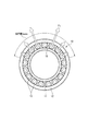
- FIG. 6 is a perspective view showing a state in which the rolling elements pass through an initial peeling portion of the inner ring of the cylindrical roller bearing. It is a top view of an inner ring explaining the exit part of the exfoliation part when performing finite element analysis in three dimensions.
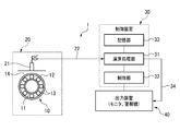
- a raceway separation progress analysis device 1 of the present embodiment analyzes a separated portion generated in a raceway ring (that is, an inner ring 11 or an outer ring 12) of a rolling bearing 10 incorporated in a mechanical equipment 20.
- the peeling progress analysis apparatus 1 receives a signal acquired by the peeling condition acquisition unit 21 that acquires the presence or absence and the shape of the rolling bearing 10 from the peeling condition, and the signal acquired by the peeling condition acquisition unit 21 through the data transmission unit 22, and performs signal processing.
- a control unit 30 having a storage unit 33 for storing the analysis result and the like, an arithmetic processing unit 31 for performing the presence/absence of separation of the bearing ring of the rolling bearing 10, and a separation progress analysis.
- the output device 40 includes a monitor, an alarm, and the like, and outputs the peeling progress analysis result and the remaining life of the rolling bearing 10.
- the rolling bearing 10 includes an inner ring 11 that is externally fitted to the rotary shaft of the mechanical equipment 20, an outer ring 12 that is internally fitted to the housing 14 and the like, and a plurality of rolling members arranged between the inner ring 11 and the outer ring 12. It has a rolling element 13 and a retainer (not shown) that holds the rolling element 13 in a rollable manner.
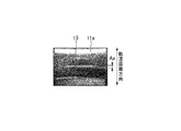
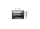
- the rolling elements 13 make line contact with the raceways of the inner ring 11 and the outer ring 12, and as shown in FIGS. 2A to 2D, the progress of delamination of the inner ring 11 (11a ⁇ 11b ⁇ 11c ⁇ 11d) occurs.
- the progress of delamination of the inner ring 11 (11a ⁇ 11b ⁇ 11c ⁇ 11d) occurs.
- a roller bearing that can be approximated in a one-dimensional manner as a change in the circumferential length A (Aa ⁇ Ab ⁇ Ac ⁇ Ad)
- a case where delamination occurs on the raceway surface of the inner ring 11 will be described as an example.
- the peeling condition acquisition means 21 any one is selected according to the method of acquiring the peeling condition.
- the peeling condition acquisition means 21 may be a fiberscope or a camera, and the shape of the peeled portion may be directly observed.
- the peeling condition acquisition means 21 may be a vibration sensor or a load sensor.
- the peeling condition acquisition means 21 may be a displacement sensor.
- the peeling condition acquisition means 21 may detect the temperature, the iron powder amount (concentration) in the lubricating oil, and the like.
- the vibration sensor, the load sensor, and the displacement sensor are fixed to the load zone of the housing 14 to which the outer ring 12, which is the fixed ring of the rolling bearing 10, is attached.
- the control device 30 is composed of a microcomputer (IC chip, CPU, MPU, DSP, etc.), and executes each processing described later by a program of this microcomputer.
- a microcomputer IC chip, CPU, MPU, DSP, etc.
- the control device 30 stores the analysis result of the separated portion of the rolling bearing 10 analyzed by the arithmetic processing unit 31 in the storage unit 33, outputs the operation of the mechanical equipment 20 to the control unit 32, and responds to the analysis result.
- the control signal for driving the mechanical equipment 20 is fed back to the operation of the mechanical equipment 20 (safe operation operation such as lowering the rotation speed). Further, the control device 30 sends the analysis result to the output device 40 by means of the data transmission means 34 using a wire or wireless considering the network.
- the output device 40 displays the analysis result of the rolling bearing 10 on a monitor or the like in real time. Further, when an abnormality is detected, an alarm device such as a light or a buzzer may be used to alert the operator to the abnormality.
- the signal data transmission unit 22 may be wired as long as it can accurately transmit and receive the signal from the peeling condition acquisition unit 21, or may be wireless in consideration of a network.
- FIG. 3 is a flow chart showing the procedure of the peeling progress analysis.
- the peeling condition obtaining means 21 For example, when the peeling condition acquisition means 21 is a fiberscope, the orbital surface is directly observed. Then, when an initial peeling portion is observed on the raceway surface, it is determined in step S2 that there is peeling, and in this embodiment, from the observed peeling portion shape, the circumferential length A (Fig. 2A to FIG. 2D). Then, the process shifts to the remaining life calculation described in detail with reference to FIG. 4 (step S3). After the remaining life calculation processing, this processing flow ends. On the other hand, if there is no peeling in step S2, this processing flow ends. The process shown in FIG. 3 is executed every predetermined time.
- FIG. 4 is a flowchart showing a procedure for calculating the relationship between the elapsed time of operation of the rolling bearing 10 and the shape of the separated portion, which corresponds to the step S3 of FIG. Therefore, when the occurrence of the peeling portion 15 is detected in step S2, the calculation of this flow is started (step S11), and the peeling shape, bearing specifications, and operating conditions are input to the calculation program (step S12).
- a bearing load which is one of the operating conditions
- a fixed bearing load which is one of the operating conditions
- a directly measured bearing load As a bearing load, which is one of the operating conditions, a fixed bearing load, a directly measured bearing load, a bearing load indirectly obtained from the power generation output, shaft rotation torque, etc. are input.
- the rotation speed the current rotation speed may be input on the assumption of continuous operation at the current rotation speed, or when the operation speed is reduced at the time when the initial peeling portion is observed. May input the decelerated rotation speed.
- the rolling element 13 that passes through the outlet of the release section changes with the expansion of the release section 15.
- the moving body load F is calculated (step S13).
- the rolling element load F is calculated by a calculation method according to ISO/TS16281. Since the axial load P pushes the inner ring 11 and pushes each rolling element 13 at the same time, the rolling element load F at the outlet of the peeling portion is calculated by solving the force balance equation.
- each rolling element 13 located in the load area Qarea has a corresponding rolling element 13 position.
- a rolling element load F 0 having a magnitude is generated.
- the moving body load F is calculated. Specifically, the rolling element loads F 0 and F 1 are obtained by the calculation method according to ISO/TS16281. Further, the rolling element load F 1 of the rolling element 13 passing through the peeling portion 15 is calculated as if no load is applied.
- the initial peeling portion generated in the center of the load zone Qarea expands in the circumferential direction of the raceway surface (the passing direction of the rolling elements 13 in the example shown in the present invention).
- the rolling element load is repeatedly applied to the crack 15a (see FIGS. 6A and 6B) at the exit of the peeling section 15, so that the crack 15a gradually propagates in the circumferential direction, and thereafter, the crack 15a has a predetermined length.
- Sano peeling piece 15b is generated stepwise.
- the rolling element load F 1 at the outlet of the portion 15 is increased and applied.
- the rolling element load F receives the rolling element load every time the circumferential length A of the peeling portion 15 becomes twice or three times the distance d between rolling element pitches. As the number decreases, it increases stepwise. Therefore, the relationship between the rolling element load F at the outlet of the peeling portion 15 and the circumferential length A of the peeling portion 15 is given.
- step S13 crack propagation analysis is performed in consideration of the shape of the advancing peeling portion, and the speed at which the peeling portion 15 expands the crack propagation speed (peel developing speed V ) Is calculated (step S14).
- the crack growth behavior in the fatigue phenomenon is governed by the linear fracture mechanics parameter K (stress intensity factor) represented by the crack length and the stress acting on the crack, and the stress intensity factor K in the region where the crack propagates stably. It is known as the following Paris law that the variation range ⁇ K (stress intensity factor range) and the crack growth amount per stress cycle da/dN have a bilogarithmic linear relationship.
- the crack growth rate can be calculated as the peeling growth rate V.
- the rolling element 13 is separated by the FEM analysis (finite element analysis) when the rolling element load F calculated in step S13 acts on the rolling bearing.
- the stress ⁇ acting on the inner ring 11 is calculated at a plurality of positions that are gradually moved from left to right from the exit end surface of the peeling portion 15 which is the exit portion of 15 to the vicinity of the crack tip (see FIG. 8B).
- the stress intensity factor range ⁇ K is calculated from the variation of the stress ⁇ at the outlet of the peeling portion 15.
- the number of rolling elements that receive a load fluctuates depending on the rotation of the bearing, but here, the maximum value is input as the rolling element load F.
- the process of calculating the stress intensity factor range ⁇ K from the calculation of the stress ⁇ by the FEM analysis can be formulated, and after the formulation, the FEM analysis can be performed by using the formula. It becomes unnecessary.
- the peeling growth rate (crack growth rate) V a J integral value that is common in fracture mechanics may be formulated in advance and used.
- bearing parameters such as the number of cylindrical rollers 13 and operating conditions such as rotation speed are applied to the crack growth amount da/dN per one cycle of the obtained stress, and the relationship between the operating time and the peel size A is applied. Is calculated from the theoretical calculation using the following formula, and the graph shown in FIG. 9 is created.
- A A 0 +da/dN ⁇ n
- a 0 Circumferential length of the peeling portion at the time of observation
- n Number of times the rolling element loads the outlet of the peeling portion within the load range
- the circumferential length A of the peeling portion 15 becomes a multiple of the distance d between rolling element pitches (correctly load the rolling element 13 among the rolling elements 13 existing in the load area Qarea). Since the rolling elements to be received decrease by one), the peeling speed V increases as the circumferential length A of the peeling portion 15 becomes a multiple of the rolling element pitch distance d.
- the change in the peeling development velocity V for each distance d between rolling element pitches appears as a bending point B in FIG. 9.
- the length A of the peeling portion 15 linearly increases along a straight line L1 in FIG. 9 (a double logarithmic graph). .. Further, when the circumferential length A of the peeling portion 15 reaches the rolling element pitch distance d, the circumferential length A of the peeling portion 15 becomes a straight line L2 having a larger gradient than the straight line L1 (the peeling progress velocity V is faster). Increases linearly along The intersection of the straight line L1 and the straight line L2 becomes the bending point B when the circumferential length A of the peeling portion 15 reaches the rolling element pitch distance d. Then, when the bending point B is exceeded, the peeling progress velocity V changes (increases) rapidly.
- FIG. 9 shows a comparison of the peeling progress analysis result obtained according to the flow chart of FIG. 3 and the test result of the peeling progress test in which the relationship between the operating time and the peeling size was investigated.
- the analysis result and the test result show similar tendencies, and it is understood that the residual life of the rolling bearing 10 can be accurately predicted by the peeling progress analysis method of the present embodiment.
- the usable time of the rolling bearing 10 after the initial peeling that is, the remaining life is determined by the acceptable degree of the failure (for example, sound or vibration) that occurs after that, and therefore it differs for each user. Therefore, it is important to know the relationship between the elapsed time and the peeling shape in advance in order to properly manage the rolling bearing 10.
- the peeling portion 15 is designated from the circumferential length A 0 of the peeling portion 15 at the time of observation.
- the elapsed time TL from T o until the shape (the circumferential length AL of the peeling portion 15) is obtained is obtained, and the remaining life of the rolling bearing 10 (that is, TL-T o ) is calculated (step S15).
- the circumferential length AL of the specified peeling portion 15 is not limited to before and after the rolling element pitch distance d, and is a value exceeding the rolling element pitch distance d when the rolling bearing 10 is in a usable state ( For example, it can be set to double or triple.
- the analysis in consideration of the increase of the rolling element load F due to the increase of the circumferential length A of the peeling portion 15 causes the rapid increase of the peeling progress and the rapid rise time of the peeling (the circumferential length A of the peeling portion 15 changes It is possible to accurately predict the time when the distance between the moving object pitches becomes a multiple. As a result, it is possible to efficiently make preparations such as prior arrangement for replacement of the rolling bearing 10.
- the present invention is not limited to the above-described embodiments, and can be modified, improved, and the like as appropriate.
- the stress variation by FEM analysis is calculated in two dimensions, but it may be calculated in three dimensions.
- the initial shape of the peeling portion 15 generated on the raceway surface 11a of the inner ring 11 is an oval shape that is long in the axial direction, as shown in FIG. 10A, and has the same circumferential length as the above embodiment. Even if the change in A does not approximate the progress of delamination, the change in stress can be calculated.
- the initial outlet of the peeling portion 15 is in the passage direction of the rolling element rather than the center position of the peeling portion 15 in the circumferential direction. ..
- a peeling progress analysis method for predicting the progress of peeling of a bearing ring of a rolling bearing having rolling elements between inner and outer races and both races, which is used in a rotating machine A step of acquiring the presence or absence of peeling and the shape of the bearing ring by a peeling condition obtaining means, Based on at least the obtained shape of the peeling portion, specifications of the rolling bearing, and operating conditions of the rolling bearing, the rolling element when the rolling element passes through the outlet of the peeling portion of the bearing ring, A step of calculating in consideration of the shape of the peeling portion that advances the rolling element load acting on Based on the rolling element load at the outlet portion of the peeling portion, a step of calculating the speed of progress of the peeling in consideration of the shape of the peeling portion that progresses, A step of calculating the relationship between the elapsed time and the shape of the peeling portion, based on the rate of progress of peeling; With A method for analysis of flaking development of rolling bearing rings.
- the progress rate of the peeling is calculated in consideration of the shape of the advancing peeling section, so the rolling It is possible to accurately predict the relationship between the elapsed time of the bearing and the shape of the peeling portion.
- the shape of the peeling portion is a circumferential length of the peeling portion
- the step of calculating the rolling element load at the outlet of the release section is given by calculating the balance of forces according to the circumferential length of the release section, and the release progress of the race ring of the rolling bearing according to (1). analysis method. According to this configuration, since the rolling element load at the outlet of the peeling portion is calculated according to the circumferential length of the peeling portion, it is possible to accurately predict the relationship between the elapsed time of the rolling bearing and the shape of the peeling portion. it can.
- the variation of the stress at the outlet of the peeling portion obtained by finite element analysis using the rolling element load at the outlet of the peeling portion is set as the stress intensity factor range.
- a delamination progress analysis device for a rolling bearing race ring which is used for a rotary machine, for predicting the progress of stripping of a rolling bearing race ring having rolling elements between inner and outer race rings and both race rings
- a peeling condition acquisition means for acquiring the presence or absence and the shape of the bearing ring, Based on at least the obtained shape of the peeling portion, the specifications of the rolling bearing, and the operating conditions of the rolling bearing, when the rolling element passes through the outlet of the peeling portion of the bearing ring, the rolling element Calculated in consideration of the shape of the peeling portion advancing the rolling element load to act, based on the rolling element load at the outlet of the peeling portion, the development speed of the peeling considering the shape of the peeling portion to progress Obtained, based on the speed of development of the peeling, a calculation unit for calculating the relationship between the elapsed time and the shape of the peeling portion, A device for analyzing flaking progress of rolling bearing rings. With this configuration, it is possible to accurately predict the relationship between the elapsed
- the relationship between the elapsed time and the shape of the peeling portion is stored in the storage unit in advance, and the release progress of the race ring of the rolling bearing according to (5). Analyzer. According to this configuration, by using the relationship between the elapsed time stored in the storage unit and the shape of the peeling portion, the calculation time for the peeling progress analysis can be shortened.
Landscapes
- Physics & Mathematics (AREA)
- General Physics & Mathematics (AREA)
- Engineering & Computer Science (AREA)
- General Engineering & Computer Science (AREA)
- Acoustics & Sound (AREA)
- Mechanical Engineering (AREA)
- Testing Of Devices, Machine Parts, Or Other Structures Thereof (AREA)
- Rolling Contact Bearings (AREA)
- Measurement Of Mechanical Vibrations Or Ultrasonic Waves (AREA)
Abstract
微小はく離発生後のはく離の進展速度に基づいて、経過時間とはく離部の形状との関係を予測することができ、適切なタイミングでの軸受交換を可能とする転がり軸受の軌道輪のはく離進展解析方法及びはく離進展解析装置を提供する。はく離取得手段(21)によって軌道輪(11)のはく離部(15)の有無及び形状を取得する工程と、少なくとも取得されたはく離部の形状、転がり軸受(10)の諸元、及び転がり軸受の運転条件に基づいて、転動体(13)が軌道輪のはく離部の出口部(15a)を通過するときの、転動体に作用する転動体荷重Fを算出する工程と、はく離部の出口部における転動体荷重Fに基づいて、進行するはく離部の形状を考慮したはく離部の進展速度Vを算出する工程と、はく離部の進展速度Vに基づいて、転がり軸受の経過時間とはく離形状との関係を算出する工程と、を備える。
Description
本発明は、転がり軸受の軌道輪のはく離進展解析方法及びはく離進展解析装置に関し、より詳細には、風力発電装置や、運搬車両を含む鉱山設備、圧延機のような鉄鋼設備などに用いられる転がり軸受の軌道輪のはく離進展解析方法及びはく離進展解析装置に関する。
転がり軸受が荷重を受けて回転すると、内輪と外輪の軌道面及び転動体の転動面は絶えず繰返し荷重を受けるので、材料の疲れによってはく離と呼ばれるうろこ状の微小な損傷が現れることがある。一般的にこのはく離によって使用不能に至るまでを軸受寿命として定義している。しかし、風力発電装置用軸受のような大形軸受の場合、交換が容易ではなく、軸受にはく離が発生しても交換部品を調達し、実際に交換できるまでに多くの期間が必要となる。このため、部品の交換ができるまでの間、発電出力を制限するなどの対策を取った上で運転が続けられることがある。しかし、交換時期が遅れることで、はく離が急速に進んでしまうと、大量のはく離片がギヤに噛み込んだり、内外輪が割れたりして、最悪の場合、装置を長期間に亘って停止するようなメンテナンス作業が必要となる場合がある。
このため、定期検査の際に、次の検査までは正常運転又は出力を制限した運転が可能か、又はどの時点で交換する必要があるかの判定が必要となってくる。このような判定の方法として、例えば、特許文献1に記載の状態監視装置は、振動センサにより検出された波形を複数の損傷フィルタ周波数帯域に分割して抽出するフィルタ処理部と、フィルタ処理後の波形からスペクトルデータを得る演算処理部と、転がり軸受の回転速度に基づいて算出した軸受損傷周波数と演算処理部で得られたスペクトルデータを比較して転がり軸受の異常部位を特定する精密診断部と、損傷フィルタ周波数帯域毎に算出される振動実効値に基づいて異常部位の損傷の程度を診断する損傷レベル診断部と、異常部位、異常部位の損傷の程度、及び回転部品の運転環境から異常部位の残存寿命を予測する残存寿命予測部と、を備え、異常部位の残存寿命を予測している。
また、特許文献2に記載の転がり軸受の状態監視装置では、転がり軸受の内外輪間のラジアル方向の相対変位を検出する変位センサが設けられ、検出された内外輪間の相対変位が、予め設定されたしきい値を超えると、転がり軸受に異常が生じたものと判定する。しきい値は、転がり軸受の負荷域中央を通過中の転動体が負荷を受けず、かつ、負荷域を通過中の残余の転動体が荷重を受けているとした場合の内外輪間の相対変位を基準変位として、該基準変位に基づいて設定される。特に、隣接する2つの転動体が同時に損傷部を通過するまでに損傷が軌道面周方向に拡大すると、荷重を受ける転動体が減少することによって転動体荷重が増大し、損傷の進展速度が上昇する点を考慮して設定された、しきい値との比較により、軸受交換時期が判定されている。
ところで、特許文献1では、転がり軸受の残存寿命予測について記載されているが、これを実際に稼動している機械(特にはく離が生じても継続使用されるケース)に適用する場合には、下記の課題が生じている。
1. 軌道面に発生した初期はく離が周方向に拡大すると、転動体がはく離を通過する際に、転動体と内外輪とのすきまにより荷重を受けることができなくなる。そのため、負荷圏にある全ての転動体が荷重を受ける理想的な転動体荷重分布に対して、荷重を支える転動体が減少し、はく離を通過する転動体の近隣の転動体荷重が増加する。しかしながら、特許文献1では、転動体荷重の増加を考慮していないため、はく離の急激な拡大を予測できない。
2. 残存寿命を予測する際に、き裂の進展速度の式に用いられる応力拡大係数範囲ΔKを算出するには,一般的に具体的な計算対象の形状が必要となる。しかしながら、はく離形状の記載がないため、寿命の予測精度が低い。
1. 軌道面に発生した初期はく離が周方向に拡大すると、転動体がはく離を通過する際に、転動体と内外輪とのすきまにより荷重を受けることができなくなる。そのため、負荷圏にある全ての転動体が荷重を受ける理想的な転動体荷重分布に対して、荷重を支える転動体が減少し、はく離を通過する転動体の近隣の転動体荷重が増加する。しかしながら、特許文献1では、転動体荷重の増加を考慮していないため、はく離の急激な拡大を予測できない。
2. 残存寿命を予測する際に、き裂の進展速度の式に用いられる応力拡大係数範囲ΔKを算出するには,一般的に具体的な計算対象の形状が必要となる。しかしながら、はく離形状の記載がないため、寿命の予測精度が低い。
また、特許文献2では、軸受交換の時期を明確にするためのしきい値の設定方法については記載されているが、はく離の進展を予測するものではなく、交換までの残存寿命が予測できず交換用軸受を事前に手配することができない。
本発明は、前述した課題に鑑みてなされたものであり、その目的は、微小はく離発生後のはく離の進展速度を算出して、経過時間とはく離部の形状との関係を予測し、適切なタイミングでの軸受交換を可能とする転がり軸受の軌道輪のはく離進展解析方法及びはく離進展解析装置を提供することにある。
本発明の上記目的は、下記の構成により達成される。
(1) 回転機械に使用される、内外軌道輪と両軌道輪間の転動体を有する転がり軸受の軌道輪のはく離の進展を予測するはく離進展解析方法であって、
はく離状況取得手段によって前記軌道輪のはく離の有無及び形状を取得する工程と、
少なくとも取得されたはく離部の形状、前記転がり軸受の諸元、及び前記転がり軸受の運転条件に基づいて、前記転動体が前記軌道輪の前記はく離部の出口部を通過するときの、前記転動体に作用する転動体荷重を算出する工程と、
前記はく離部の出口部における転動体荷重に基づいて、進行する前記はく離部の形状を考慮した前記はく離の進展速度を算出する工程と、
前記はく離の進展速度に基づいて、経過時間とはく離部の形状との関係を算出する工程と、
を備える、
転がり軸受の軌道輪のはく離進展解析方法。
(2) 回転機械に使用される、内外軌道輪と両軌道輪間の転動体を有する転がり軸受の軌道輪のはく離の進展を予測する転がり軸受の軌道輪のはく離進展解析装置であって、
前記軌道輪のはく離の有無及び形状を取得するはく離状況取得手段と、
少なくとも取得されたはく離部の形状、前記転がり軸受の諸元、前記転がり軸受の運転条件に基づいて、前記転動体が前記軌道輪の前記はく離部の出口部を通過するときの、前記転動体に作用する転動体荷重を算出し、前記はく離部の出口部における転動体荷重に基づいて、進行する前記はく離部の形状を考慮した前記はく離の進展速度を求め、前記はく離の進展速度に基づいて、経過時間とはく離部の形状との関係を算出する演算部と、
を備える転がり軸受の軌道輪のはく離進展解析装置。
(1) 回転機械に使用される、内外軌道輪と両軌道輪間の転動体を有する転がり軸受の軌道輪のはく離の進展を予測するはく離進展解析方法であって、
はく離状況取得手段によって前記軌道輪のはく離の有無及び形状を取得する工程と、
少なくとも取得されたはく離部の形状、前記転がり軸受の諸元、及び前記転がり軸受の運転条件に基づいて、前記転動体が前記軌道輪の前記はく離部の出口部を通過するときの、前記転動体に作用する転動体荷重を算出する工程と、
前記はく離部の出口部における転動体荷重に基づいて、進行する前記はく離部の形状を考慮した前記はく離の進展速度を算出する工程と、
前記はく離の進展速度に基づいて、経過時間とはく離部の形状との関係を算出する工程と、
を備える、
転がり軸受の軌道輪のはく離進展解析方法。
(2) 回転機械に使用される、内外軌道輪と両軌道輪間の転動体を有する転がり軸受の軌道輪のはく離の進展を予測する転がり軸受の軌道輪のはく離進展解析装置であって、
前記軌道輪のはく離の有無及び形状を取得するはく離状況取得手段と、
少なくとも取得されたはく離部の形状、前記転がり軸受の諸元、前記転がり軸受の運転条件に基づいて、前記転動体が前記軌道輪の前記はく離部の出口部を通過するときの、前記転動体に作用する転動体荷重を算出し、前記はく離部の出口部における転動体荷重に基づいて、進行する前記はく離部の形状を考慮した前記はく離の進展速度を求め、前記はく離の進展速度に基づいて、経過時間とはく離部の形状との関係を算出する演算部と、
を備える転がり軸受の軌道輪のはく離進展解析装置。
本発明の軌道輪のはく離進展解析方法及び軌道輪のはく離進展解析装置によれば、転動体が軌道輪のはく離部の出口部を通過するときに作用する転動体荷重から、進行するはく離部の形状を考慮したはく離の進展速度を求めて、経過時間とはく離部の形状との関係を予測するようにしたので、適切なタイミングでの軸受交換が可能となる。
以下、本発明の一実施形態に係る転がり軸受の軌道輪のはく離進展解析方法及びはく離進展解析装置を図面に基づいて詳細に説明する。
図1に示すように、本実施形態の軌道輪のはく離進展解析装置1は、機械設備20に組み込まれた転がり軸受10の軌道輪(即ち、内輪11又は外輪12)に発生したはく離部を解析するものである。はく離進展解析装置1は、転がり軸受10のはく離の有無及び形状を取得するはく離状況取得手段21と、はく離状況取得手段21で取得した信号をデータ伝送手段22を介して受信し、信号処理を行って転がり軸受10の軌道輪のはく離の有無、及びはく離進展解析を行う演算処理部31、機械設備20を駆動制御する制御部32、及び解析結果などを記憶する記憶部33を有する制御装置30と、モニタや警報機等からなり、はく離進展解析結果や転がり軸受10の残存寿命を出力する出力装置40と、を備えている。
転がり軸受10は、機械設備20の回転軸に外嵌される内輪11と、ハウジング14等に内嵌される外輪12と、内輪11及び外輪12との間で転動可能に配置された複数の転動体13と、転動体13を転動自在に保持する不図示の保持器と、を有する。
なお、本実施形態では、転動体13と内輪11及び外輪12の軌道面が線接触し、図2A~図2Dに示すように、内輪11のはく離の進展(11a→11b→11c→11d)が、周方向長さAの変化(Aa→Ab→Ac→Ad)として一次元で近似できるころ軸受を想定し、内輪11の軌道面にはく離が発生する場合を例に説明する。
はく離状況取得手段21は、はく離状況の取得方法に応じて、任意のものが選択される。例えば、はく離状況取得手段21をファイバースコープやカメラとして、はく離部の形状を直接観察してもよい。或いは、本出願人が考案した日本国特願2018-156535に記載のはく離部の長さを検出する方法の場合には、はく離状況取得手段21は振動センサや荷重センサであってもよく、また、特許文献2に記載のはく離の長さを検出する方法の場合には、はく離状況取得手段21は変位センサであってもよい。さらに、はく離状況取得手段21は、温度や、潤滑油中の鉄粉量(濃度)などを検出するものであってもよい。なお、振動センサ、荷重センサ、変位センサは、転がり軸受10の固定輪である外輪12が取り付けられたハウジング14の負荷圏に固定される。
制御装置30は、マイクロコンピュータ(ICチップ、CPU、MPU、DSP等)により構成されており、後述する各処理をこのマイクロコンピュータのプログラムにより実行する。
制御装置30は、演算処理部31で解析された転がり軸受10のはく離部の解析結果を、記憶部33に記憶すると共に、機械設備20の動作を制御部32へ出力し、解析結果に応じた機械設備20を駆動する制御信号を機械設備20の動作にフィードバック(回転数を落とすなどの安全運転動作)する。さらに、制御装置30は、有線又はネットワークを考慮した無線を利用したデータ伝送手段34により解析結果を出力装置40に送る。
出力装置40は、転がり軸受10の解析結果をモニタ等にリアルタイムで表示する。また、異常が検出された場合に、ライトやブザー等の警報機を用いてオペレータに異常であることの注意を促すようにしてもよい。また、信号のデータ伝送手段22は、はく離状況取得手段21からの信号を的確に送受信可能であればよいので、有線でも良いし、ネットワークを考慮した無線を利用してもよい。
図3は、はく離進展解析の手順を示すフローチャートである。まず、はく離状況取得手段21によりはく離の有無及び形状を取得する(ステップS1)。例えば、はく離状況取得手段21が、ファイバースコープの場合、軌道面が直接観察される。そして、軌道面に初期はく離部が観察された場合には、ステップS2で、はく離有りとして、本実施形態では、観察されたはく離部の形状から、はく離部の形状の周方向長さA(図2A~図2D参照)を取得する。そして、図4を用いて詳述する残存寿命計算に移行する(ステップS3)。残存寿命計算の処理の後、本処理フローを終了する。一方、ステップS2で、はく離無しの場合には、本処理フローを終了する。図3に示す処理を所定時間毎に実行する。
図4は、転がり軸受10の運転経過時間とはく離部の形状との関係を算出する手順を示すフローチャートであり、図3のステップS3の工程に対応する。したがって、上記ステップS2ではく離部15の発生を検知した場合に、本フローの計算を開始し(ステップS11)、はく離形状、軸受諸元、運転条件を演算プログラムに入力する(ステップS12)。
運転条件の一つである軸受荷重としては、一定の軸受荷重、直接測定した軸受荷重、発電出力や軸の回転トルクなどから間接的に求めた軸受荷重などが入力される。また、予め想定された運転荷重パターンを入力してもよい。また、回転速度としては、現在の回転速度で継続運転した場合を想定して、現在の回転速度が入力されてもよいし、初期はく離部が観察された時点で、運転速度を減速する場合には、減速した回転速度が入力されてもよい。
次いで、ステップS12で入力した指標(即ち、初期はく離形状、軸受諸元、運転条件)に基づいて、はく離部15の拡大に伴って変化する、はく離部の出口部を通過する転動体13の転動体荷重Fを算出する(ステップS13)。ここでは、ISO/TS16281に準じた計算方法により転動体荷重Fを計算する。軸荷重Pが内輪11を押し各転動体13を同時に押すため、力のつりあい式を解くことで、はく離部の出口部の転動体荷重Fを算出する。
図5Aに示すように、軸荷重Pにより内輪11にラジアル軸受荷重が作用した状態で転がり軸受10が回転すると、負荷圏Qareaに位置する各転動体13には、転動体13の位置に応じた大きさの転動体荷重F0が発生する。
一方、転動体13と内輪11の軌道面との接触面圧が最大となる負荷圏Qarea中央において、内輪11の軌道面にはく離が発生すると、図5Bに示すように、はく離部15を通過している転動体13は軸受荷重を支持することができず、図5Aに示した負荷圏Qareaの転動体13よりも少ない数の転動体13で軸受荷重を支持するため、その他の負荷圏Qareaに位置する各転動体13に増大した転動体荷重F1が負荷される。したがって、図5Aにおける各転動体13の転動体荷重F0の関係を用いて、図5Bにおける力のつりあい式を解くことで、初期はく離部が生じた状態での、はく離部の出口部の転動体荷重Fが算出される。具体的には、転動体荷重F0及びF1は、ISO/TS16281に準じた計算方法により求められる。また、はく離部15を通過している転動体13の転動体荷重F1は、荷重を受けないものとして計算される。
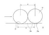
また、負荷圏Qarea中央に生じた初期はく離部は、軌道面の円周方向(本発明に示した例においては転動体13の通過方向)に拡大していく。通常、はく離部15の出口部におけるき裂15a(図6A,図6B参照)に転動体荷重が繰り返し負荷されることで、き裂15aは円周方向に徐々に進展し、その後、所定の長さのはく離片15bが段階的に発生する。そして、図6Bに示すように、はく離部15の周方向長さAが、隣り合う2つの転動体13が同時に入る長さ(周方向長さA=転動体ピッチ間距離d)になると、はく離部15の出口部おける転動体荷重F1は増大して負荷されるようになる。
その後、転動体荷重Fは、図7に示すように、はく離部15の周方向長さAが、転動体ピッチ間距離d、その2倍、3倍となる毎に転動体荷重を受ける転動体数が減少していくので階段状に増大する。したがって、はく離部15の出口部における転動体荷重Fと、はく離部15の周方向長さAとの関係が、与えられる。
そして、ステップS13で算出された転動体荷重Fに基づいて,進行するはく離部の形状を考慮したき裂進展解析を行い,き裂の進展速度をはく離部15が拡大する速度(はく離進展速度V)として算出する(ステップS14)。
疲労現象におけるき裂進展挙動は、き裂長さとき裂に働く応力で表される線形破壊力学パラメータK(応力拡大係数)に支配され、き裂が安定して進展する領域では、応力拡大係数Kの変動範囲ΔK(応力拡大係数範囲)と応力1サイクルあたりのき裂進展量da/dNは両対数直線関係となることが、下記するParis則として知られている。
da/dN=C(ΔK)m
但し、C、mは、実験定数
従って、上式にΔKを代入することで、本発明では、き裂進展速度をはく離進展速度Vとして演算により求めることができる。具体的には、図8Aおよび図8Bに一例を示すように、ステップS13で算出された転動体荷重Fが転がり軸受に作用した場合のFEM解析(有限要素解析)により、転動体13をはく離部15の出口部である、はく離部15の出口端面からき裂先端を越えた付近まで(図8B参照)左から右に少しずつ動かした複数の位置で、内輪11に作用する各応力σを算出し、はく離部15の出口部における応力σの変動から応力拡大係数範囲ΔKを算出する。なお、実際には、荷重を受ける転動体の数は、軸受の回転に応じて変動するが、ここでは、最大値を転動体荷重Fとして入力している。また、FEM解析による応力σの算出から応力拡大係数範囲ΔKを算出する過程は、定式化することができ、定式化した後は、該式を用いて計算することで、その都度のFEM解析は不要となる。
なお、はく離進展速度(き裂進展速度)Vは、破壊力学で一般的なJ積分値を予め定式化して用いてもよい。
但し、C、mは、実験定数
従って、上式にΔKを代入することで、本発明では、き裂進展速度をはく離進展速度Vとして演算により求めることができる。具体的には、図8Aおよび図8Bに一例を示すように、ステップS13で算出された転動体荷重Fが転がり軸受に作用した場合のFEM解析(有限要素解析)により、転動体13をはく離部15の出口部である、はく離部15の出口端面からき裂先端を越えた付近まで(図8B参照)左から右に少しずつ動かした複数の位置で、内輪11に作用する各応力σを算出し、はく離部15の出口部における応力σの変動から応力拡大係数範囲ΔKを算出する。なお、実際には、荷重を受ける転動体の数は、軸受の回転に応じて変動するが、ここでは、最大値を転動体荷重Fとして入力している。また、FEM解析による応力σの算出から応力拡大係数範囲ΔKを算出する過程は、定式化することができ、定式化した後は、該式を用いて計算することで、その都度のFEM解析は不要となる。
なお、はく離進展速度(き裂進展速度)Vは、破壊力学で一般的なJ積分値を予め定式化して用いてもよい。
そして、求められた応力1サイクルあたりのき裂進展量da/dNに、円筒ころ13の数などの軸受諸元、回転速度などの運転条件を適用して、運転時間とはく離サイズAとの関係を、下記式を用いた理論計算から算出して、図9に示すグラフを作成する。
A=A0+da/dN×n
A0:観察された時点のはく離部の周方向長さ
n:転動体が、負荷圏内ではく離部の出口部を負荷する回数
A0:観察された時点のはく離部の周方向長さ
n:転動体が、負荷圏内ではく離部の出口部を負荷する回数
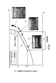
図7において説明したように、転動体荷重Fは、はく離部15の周方向長さAが転動体ピッチ間距離dの倍数になる(負荷圏Qareaに存在する転動体13のうち、正しく負荷を受ける転動体が1つ減る)ごとに階段状に増大するので、はく離進展速度Vもはく離部15の周方向長さAが転動体ピッチ間距離dの倍数になるごとに速くなる。この転動体ピッチ間距離dごとのはく離進展速度Vの変化は、図9において屈曲点Bとして現れる。
詳細には、はく離部15の周方向長さAが転動体ピッチ間距離d未満のときに、はく離部の長さAは図9(両対数グラフ)において直線L1に沿って直線的に増大する。また、はく離部15の周方向長さAが転動体ピッチ間距離dに達すると、はく離部15の周方向長さAは、直線L1より勾配の大きな(はく離進展速度Vが速い)直線L2に沿って直線的に増大する。直線L1と直線L2との交点が、はく離部15の周方向長さAが転動体ピッチ間距離dに達したときの屈曲点Bとなる。そして、屈曲点Bを越えるとはく離進展速度Vが急激に変化(増加)する。
図9には、図3のフローチャートに従って求めたはく離進展解析結果と、運転時間とはく離サイズとの関係を調べたはく離進展試験の試験結果とを比較して示している。図9から分かるように、解析結果と試験結果とは、近似した傾向を示しており、本実施形態のはく離進展解析方法により転がり軸受10の残存寿命を精度よく予測可能であることが分かる。
なお、初期はく離が発生した後の転がり軸受10の使用可能時間、即ち、残存寿命は、その後に発生する障害(例えば、音や振動)の許容可能な程度によって決まるため、使用者ごとに異なる。従って、経過時間とはく離形状との関係を予め知ることは、転がり軸受10を適切に管理する上で重要である。
次いで、図9に基づいて、転がり軸受10を使用可能なはく離部の周方向長さALを指定することで、観察された時点のはく離部15の周方向長さA0からはく離部15が指定した形状(はく離部15の周方向長さAL)になるまでのToからの経過時間TLを求め、転がり軸受10の残存寿命(即ち、TL-To)を算出する(ステップS15)。
このように、残存寿命を、はく離進展速度Vが急激に大きくなる屈曲点Bに達するまでの残り時間から求めれば、急激なはく離進展による想定外の障害発生を防止することができるので好ましい。なお、指定するはく離部15の周方向長さALは、転動体ピッチ間距離dの前後に限定されず、転がり軸受10が使用可能な状態であれば、転動体ピッチ間距離dを越える値(例えば2倍や3倍)に設定することもできる。
なお、上述した図4のフローチャートの手順は、各転がり軸受の諸元ごとに、所定の運転条件に対して、軸受寿命として想定される最大はく離部の長さまで予め計算しておき、その計算結果のデータをテーブル化して記憶部33に記憶しておいてもよい。
このように、はく離部15の周方向長さAの拡大による転動体荷重Fの増加を考慮した解析により、はく離進展の急上昇、及びはく離の急上昇時期(はく離部15の周方向長さAが転動体ピッチ間距離dの倍数になる時期)を精度よく予測することができる。これにより、転がり軸受10の交換の事前手配などの準備を効率的に行うことが可能となる。
尚、本発明は、前述した各実施形態に限定されるものではなく、適宜、変形、改良、等が可能である。
例えば、上記実施形態では、FEM解析による応力の変動を2次元で計算しているが、3次元で計算することもできる。この場合、内輪11の軌道面11aに発生する初期のはく離部15の形状が、図10Aに示すように、軸方向に長い長円状であって、上記実施形態のように、周方向長さAの変化としてはく離の進展を近似しない場合であっても、応力の変動を計算することができる。
ここで、3次元で応力の変動を計算する際には、図10Bに示すように、初期のはく離部15の出口部は、はく離部15の周方向中央位置よりも転動体の通過方向となる。
例えば、上記実施形態では、FEM解析による応力の変動を2次元で計算しているが、3次元で計算することもできる。この場合、内輪11の軌道面11aに発生する初期のはく離部15の形状が、図10Aに示すように、軸方向に長い長円状であって、上記実施形態のように、周方向長さAの変化としてはく離の進展を近似しない場合であっても、応力の変動を計算することができる。
ここで、3次元で応力の変動を計算する際には、図10Bに示すように、初期のはく離部15の出口部は、はく離部15の周方向中央位置よりも転動体の通過方向となる。
また、この場合も、転動体13がはく離部15内に位置した際には、荷重を受けないことから、はく離部15の周方向長さが転動体ピッチ間距離dの倍数となる毎に、転動体荷重Fが階段状に増大し、併せて、はく離進展速度が急激に変化する点は、上記実施形態と同様である。
以上の通り、本明細書には次の事項が開示されている。
(1) 回転機械に使用される、内外軌道輪と両軌道輪間の転動体を有する転がり軸受の軌道輪のはく離の進展を予測するはく離進展解析方法であって、
はく離状況取得手段によって前記軌道輪のはく離の有無及び形状を取得する工程と、
少なくとも取得された前記はく離部の形状、前記転がり軸受の諸元、及び前記転がり軸受の運転条件に基づいて、前記転動体が前記軌道輪のはく離部の出口部を通過するときの、前記転動体に作用する転動体荷重を進行する前記はく離部の形状を考慮して算出する工程と、
前記はく離部の出口部における転動体荷重に基づいて、進行する前記はく離部の形状を考慮した前記はく離の進展速度を算出する工程と、
前記はく離の進展速度に基づいて、経過時間とはく離部の形状との関係を算出する工程と、
を備える、
転がり軸受の軌道輪のはく離進展解析方法。
この構成によれば、初期はく離発生後に転動体がはく離部の出口部を通過するときの転動体荷重に基づいて、進行するはく離部の形状を考慮してはく離の進展速度を算出するので、転がり軸受の経過時間とはく離部の形状との関係を精度よく予測することができる。
(1) 回転機械に使用される、内外軌道輪と両軌道輪間の転動体を有する転がり軸受の軌道輪のはく離の進展を予測するはく離進展解析方法であって、
はく離状況取得手段によって前記軌道輪のはく離の有無及び形状を取得する工程と、
少なくとも取得された前記はく離部の形状、前記転がり軸受の諸元、及び前記転がり軸受の運転条件に基づいて、前記転動体が前記軌道輪のはく離部の出口部を通過するときの、前記転動体に作用する転動体荷重を進行する前記はく離部の形状を考慮して算出する工程と、
前記はく離部の出口部における転動体荷重に基づいて、進行する前記はく離部の形状を考慮した前記はく離の進展速度を算出する工程と、
前記はく離の進展速度に基づいて、経過時間とはく離部の形状との関係を算出する工程と、
を備える、
転がり軸受の軌道輪のはく離進展解析方法。
この構成によれば、初期はく離発生後に転動体がはく離部の出口部を通過するときの転動体荷重に基づいて、進行するはく離部の形状を考慮してはく離の進展速度を算出するので、転がり軸受の経過時間とはく離部の形状との関係を精度よく予測することができる。
(2) 前記はく離部の形状は、前記はく離部の周方向長さであり、
前記はく離部の出口部における転動体荷重の算出工程は、はく離部の周方向長さに応じた力のつり合いを計算することで与えられる、(1)に記載の転がり軸受の軌道輪のはく離進展解析方法。
この構成によれば、はく離部の周方向長さに応じてはく離部の出口部における転動体荷重を算出するので、転がり軸受における経過時間とはく離部の形状との関係を精度よく予測することができる。
前記はく離部の出口部における転動体荷重の算出工程は、はく離部の周方向長さに応じた力のつり合いを計算することで与えられる、(1)に記載の転がり軸受の軌道輪のはく離進展解析方法。
この構成によれば、はく離部の周方向長さに応じてはく離部の出口部における転動体荷重を算出するので、転がり軸受における経過時間とはく離部の形状との関係を精度よく予測することができる。
(3) 前記はく離の進展速度算出工程は、前記はく離部の出口部における転動体荷重を用いた有限要素解析によって得られた前記はく離部の出口部における応力の変動を応力拡大係数範囲としたき裂進展速度によって与えられる、(2)に記載の転がり軸受の軌道輪のはく離進展解析方法。
この構成によれば、Paris則に基づいてはく離の進展速度を解析することができる。
この構成によれば、Paris則に基づいてはく離の進展速度を解析することができる。
(4) 予め指定した前記はく離部の形状になるまでの残存時間を残存寿命として出力する工程をさらに備える、(1)~(3)のいずれかに記載の転がり軸受の軌道輪のはく離進展解析方法。
この構成によれば、転がり軸受の残存寿命を精度よく予測することができる。
この構成によれば、転がり軸受の残存寿命を精度よく予測することができる。
(5) 回転機械に使用される、内外軌道輪と両軌道輪間の転動体を有する転がり軸受の軌道輪のはく離の進展を予測する転がり軸受の軌道輪のはく離進展解析装置であって、
前記軌道輪のはく離の有無及び形状を取得するはく離状況取得手段と、
少なくとも取得されたはく離部の形状、前記転がり軸受の諸元、前記転がり軸受の運転条件に基づいて、前記転動体が前記軌道輪の前記はく離部の出口部を通過するときの、前記転動体に作用する転動体荷重を進行する前記はく離部の形状を考慮して算出し、前記はく離部の出口部における転動体荷重に基づいて、進行する前記はく離部の形状を考慮した前記はく離の進展速度を求め、前記はく離の進展速度に基づいて、経過時間とはく離部の形状との関係を算出する演算部と、
を備える転がり軸受の軌道輪のはく離進展解析装置。
この構成によれば、転がり軸受の運転経過時間とはく離部の形状との関係を精度よく予測することができる。
前記軌道輪のはく離の有無及び形状を取得するはく離状況取得手段と、
少なくとも取得されたはく離部の形状、前記転がり軸受の諸元、前記転がり軸受の運転条件に基づいて、前記転動体が前記軌道輪の前記はく離部の出口部を通過するときの、前記転動体に作用する転動体荷重を進行する前記はく離部の形状を考慮して算出し、前記はく離部の出口部における転動体荷重に基づいて、進行する前記はく離部の形状を考慮した前記はく離の進展速度を求め、前記はく離の進展速度に基づいて、経過時間とはく離部の形状との関係を算出する演算部と、
を備える転がり軸受の軌道輪のはく離進展解析装置。
この構成によれば、転がり軸受の運転経過時間とはく離部の形状との関係を精度よく予測することができる。
(6) 前記転がり軸受の諸元に応じて、前記経過時間と前記はく離部の形状との関係は、予め記憶部に格納されている、(5)に記載の転がり軸受の軌道輪のはく離進展解析装置。
この構成によれば、記憶部に格納された経過時間とはく離部の形状との関係を用いることで、はく離進展解析の演算時間を短縮することができる。
この構成によれば、記憶部に格納された経過時間とはく離部の形状との関係を用いることで、はく離進展解析の演算時間を短縮することができる。
以上、図面を参照しながら各種の実施の形態について説明したが、本発明はかかる例に限定されないことは言うまでもない。当業者であれば、特許請求の範囲に記載された範疇内において、各種の変更例又は修正例に想到し得ることは明らかであり、それらについても当然に本発明の技術的範囲に属するものと了解される。また、発明の趣旨を逸脱しない範囲において、上記実施の形態における各構成要素を任意に組み合わせてもよい。
なお、本出願は、2019年2月19日出願の日本特許出願(特願2019-027618)に基づくものであり、その内容は本出願の中に参照として援用される。
1 はく離進展解析装置
10 転がり軸受
11 内輪(軌道輪)
12 外輪(軌道輪)
13 円筒ころ(転動体)
15 はく離部
15a はく離部の出口部のき裂
20 回転機械(機械設備)
21 はく離状況取得手段
31 演算処理部
33 記憶部
A はく離部の周方向長さ
F,F0、F1 転動体荷重
K 応力拡大係数
t 運転経過時間
V はくり離進展速度(き裂進展速度)
ΔK 応力拡大係数範囲
10 転がり軸受
11 内輪(軌道輪)
12 外輪(軌道輪)
13 円筒ころ(転動体)
15 はく離部
15a はく離部の出口部のき裂
20 回転機械(機械設備)
21 はく離状況取得手段
31 演算処理部
33 記憶部
A はく離部の周方向長さ
F,F0、F1 転動体荷重
K 応力拡大係数
t 運転経過時間
V はくり離進展速度(き裂進展速度)
ΔK 応力拡大係数範囲
Claims (6)
- 回転機械に使用される、内外軌道輪と両軌道輪間の転動体を有する転がり軸受の軌道輪のはく離の進展を予測するはく離進展解析方法であって、
はく離状況取得手段によって前記軌道輪のはく離の有無及び形状を取得する工程と、
少なくとも取得されたはく離部の形状、前記転がり軸受の諸元、及び前記転がり軸受の運転条件に基づいて、前記転動体が前記軌道輪の前記はく離部の出口部を通過するときの、前記転動体に作用する転動体荷重を進行する前記はく離部の形状を考慮して算出する工程と、
前記はく離部の出口部における転動体荷重に基づいて、進行する前記はく離部の形状を考慮した前記はく離の進展速度を算出する工程と、
前記はく離の進展速度に基づいて、経過時間とはく離部の形状との関係を算出する工程と、
を備える、
転がり軸受の軌道輪のはく離進展解析方法。 - 前記はく離部の形状は、前記はく離部の周方向長さであり、
前記はく離部の出口部における転動体荷重の算出工程は、はく離部の周方向長さに応じた力のつり合いを計算することで与えられる、請求項1に記載の転がり軸受の軌道輪のはく離進展解析方法。 - 前記はく離の進展速度算出工程は、前記はく離部の出口部における転動体荷重を用いた有限要素解析によって得られた前記はく離部の出口部における応力の変動を応力拡大係数範囲としたき裂進展速度によって与えられる、請求項2に記載の転がり軸受の軌道輪のはく離進展解析方法。
- 予め指定した前記はく離部の形状になるまでの残存時間を残存寿命として出力する工程をさらに備える、請求項1~3のいずれか1項に記載の転がり軸受の軌道輪のはく離進展解析方法。
- 回転機械に使用される、内外軌道輪と両軌道輪間の転動体を有する転がり軸受の軌道輪のはく離の進展を予測する転がり軸受の軌道輪のはく離進展解析装置であって、
前記軌道輪のはく離の有無及び形状を取得するはく離状況取得手段と、
少なくとも取得された前記はく離部の形状、前記転がり軸受の諸元、前記転がり軸受の運転条件に基づいて、前記転動体が前記軌道輪のはく離部の出口部を通過するときの、前記転動体に作用する転動体荷重を進行する前記はく離部の形状を考慮して算出し、前記はく離部の出口部における転動体荷重に基づいて、進行する前記はく離部の形状を考慮した前記はく離の進展速度を求め、前記はく離の進展速度に基づいて、経過時間とはく離部の形状との関係を算出する演算部と、
を備える転がり軸受の軌道輪のはく離進展解析装置。 - 前記転がり軸受の諸元に応じて、前記経過時間と前記はく離部の形状との関係は、予め記憶部に格納されている、請求項5に記載の転がり軸受の軌道輪のはく離進展解析装置。
Priority Applications (2)
| Application Number | Priority Date | Filing Date | Title |
|---|---|---|---|
| JP2020567996A JP6844764B2 (ja) | 2019-02-19 | 2020-02-19 | 転がり軸受の軌道輪のはく離進展解析方法及びはく離進展解析装置 |
| US17/426,375 US11280699B2 (en) | 2019-02-19 | 2020-02-19 | Flaking development analysis method and flaking development analysis device for raceway ring of rolling bearing |
Applications Claiming Priority (2)
| Application Number | Priority Date | Filing Date | Title |
|---|---|---|---|
| JP2019-027618 | 2019-02-19 | ||
| JP2019027618 | 2019-02-19 |
Publications (1)
| Publication Number | Publication Date |
|---|---|
| WO2020171142A1 true WO2020171142A1 (ja) | 2020-08-27 |
Family
ID=72144385
Family Applications (1)
| Application Number | Title | Priority Date | Filing Date |
|---|---|---|---|
| PCT/JP2020/006622 Ceased WO2020171142A1 (ja) | 2019-02-19 | 2020-02-19 | 転がり軸受の軌道輪のはく離進展解析方法及びはく離進展解析装置 |
Country Status (3)
| Country | Link |
|---|---|
| US (1) | US11280699B2 (ja) |
| JP (2) | JP6844764B2 (ja) |
| WO (1) | WO2020171142A1 (ja) |
Cited By (2)
| Publication number | Priority date | Publication date | Assignee | Title |
|---|---|---|---|---|
| JP2022185599A (ja) * | 2021-06-03 | 2022-12-15 | 日本精工株式会社 | 転がり軸受の異常診断方法及び異常診断装置 |
| WO2024247532A1 (ja) * | 2023-05-31 | 2024-12-05 | 日本精工株式会社 | 軸受残存寿命診断方法及び軸受残存寿命診断装置 |
Families Citing this family (8)
| Publication number | Priority date | Publication date | Assignee | Title |
|---|---|---|---|---|
| CN112639394B (zh) * | 2018-08-21 | 2023-05-12 | 瓦锡兰芬兰有限公司 | 滑动轴承紧余量高度测量方法和装置 |
| US12234863B2 (en) * | 2021-08-05 | 2025-02-25 | Aktiebolaget Skf | Method of determining the center of loading of a rolling element |
| DE102021211493A1 (de) * | 2021-10-12 | 2023-04-13 | Aktiebolaget Skf | Vorrichtung und Verfahren zum Abschätzen einer Last in einem Lager |
| CN114414236B (zh) * | 2022-01-17 | 2022-09-27 | 西安交通大学 | 齿轮传动系统故障信号强度与传递特性表征方法及系统 |
| WO2024004051A1 (ja) * | 2022-06-28 | 2024-01-04 | 株式会社ジェイテクト | 転がり軸受の検査方法 |
| JP7601123B2 (ja) | 2023-01-11 | 2024-12-17 | 日本精工株式会社 | 軸受の軌道輪のはく離進展解析方法、はく離解析装置、およびプログラム |
| CN118730531B (zh) * | 2024-06-17 | 2025-03-21 | 深圳市幸福半导体科技有限公司 | 一种转塔式摆盘机运行异常监测方法 |
| CN121835080A (zh) * | 2026-03-12 | 2026-04-10 | 昆明理工大学 | 一种深沟球轴承外圈初期剥落扩展演化引起ias响应扰动的动力学建模方法 |
Citations (4)
| Publication number | Priority date | Publication date | Assignee | Title |
|---|---|---|---|---|
| JPH051985A (ja) * | 1991-06-25 | 1993-01-08 | Nippon Seiko Kk | 軸受内輪の疲労き裂進展速度の測定方法 |
| US20110224917A1 (en) * | 2010-03-12 | 2011-09-15 | Honeywell International Inc. | Method and system for detecting incipient bearing failures |
| JP2014020778A (ja) * | 2012-07-12 | 2014-02-03 | Ntn Corp | 転がり軸受の寿命推定装置および寿命推定方法 |
| WO2020040280A1 (ja) * | 2018-08-23 | 2020-02-27 | 日本精工株式会社 | 転がり軸受の異常診断方法及び異常診断装置 |
Family Cites Families (8)
| Publication number | Priority date | Publication date | Assignee | Title |
|---|---|---|---|---|
| JP4006972B2 (ja) * | 2000-12-25 | 2007-11-14 | 日本精工株式会社 | 転がり軸受 |
| US7686516B2 (en) * | 2004-05-26 | 2010-03-30 | Nsk Ltd. | Rolling bearing unit with load measuring unit |
| JP2006256471A (ja) * | 2005-03-17 | 2006-09-28 | Denso Corp | エンジンベルトシステム |
| JP4363346B2 (ja) * | 2005-03-18 | 2009-11-11 | 株式会社デンソー | 車両用補機の軸受け装置 |
| CN102597734B (zh) * | 2009-08-27 | 2015-08-26 | Skf公司 | 轴承生命周期预测学 |
| WO2016099375A1 (en) * | 2014-12-16 | 2016-06-23 | Aktiebolaget Skf | Bearing component and method of manufacture |
| JP6654002B2 (ja) | 2015-07-22 | 2020-02-26 | Ntn株式会社 | 転がり軸受の異常判定しきい値の設定方法、及び転がり軸受の状態監視方法 |
| JP2017219469A (ja) | 2016-06-09 | 2017-12-14 | 日本精工株式会社 | 状態監視装置及び状態監視方法 |
-
2020
- 2020-02-19 JP JP2020567996A patent/JP6844764B2/ja active Active
- 2020-02-19 US US17/426,375 patent/US11280699B2/en active Active
- 2020-02-19 WO PCT/JP2020/006622 patent/WO2020171142A1/ja not_active Ceased
-
2021
- 2021-02-22 JP JP2021026339A patent/JP2021103170A/ja active Pending
Patent Citations (4)
| Publication number | Priority date | Publication date | Assignee | Title |
|---|---|---|---|---|
| JPH051985A (ja) * | 1991-06-25 | 1993-01-08 | Nippon Seiko Kk | 軸受内輪の疲労き裂進展速度の測定方法 |
| US20110224917A1 (en) * | 2010-03-12 | 2011-09-15 | Honeywell International Inc. | Method and system for detecting incipient bearing failures |
| JP2014020778A (ja) * | 2012-07-12 | 2014-02-03 | Ntn Corp | 転がり軸受の寿命推定装置および寿命推定方法 |
| WO2020040280A1 (ja) * | 2018-08-23 | 2020-02-27 | 日本精工株式会社 | 転がり軸受の異常診断方法及び異常診断装置 |
Non-Patent Citations (3)
| Title |
|---|
| CHIFU, TAKETOSHI ET AL.: "Analysis Prediction Technique of Flaking Expansion in Roller Bearings for Wind turbines", NSK TECHNICAL JOURNAL, vol. 691, 21 January 2019 (2019-01-21), pages 65 - 73 * |
| SHO HASHIMOTO, KOMATA HIROKI, MATSUNAGA HISAO: "Quantitative Evaluation of Rolling Fatigue Strength with Consideration of Small Cracks Originating from Drilled Holes'' (HASHIMOTO, Sho et al. Effect of small defect on the flaking strength of rolling bearings (Part 2: Evaluation of the flaking strength of rolling bearing having a small drilled hole", TRANSACTIONS OF THE JSME, vol. 83, no. 852, 2017, pages 1 - 12, XP055735061 * |
| TOUMI, M. Y. ET AL.: "Numerical simulation and experimental comparison of flaw evolution on a bearing raceway: Case of thrust ball bearing", JOURNAL OF COMPUTATIONAL DESIGN AND ENGINEERING, vol. 5, 2018, pages 427 - 434, XP055735067 * |
Cited By (3)
| Publication number | Priority date | Publication date | Assignee | Title |
|---|---|---|---|---|
| JP2022185599A (ja) * | 2021-06-03 | 2022-12-15 | 日本精工株式会社 | 転がり軸受の異常診断方法及び異常診断装置 |
| JP7552507B2 (ja) | 2021-06-03 | 2024-09-18 | 日本精工株式会社 | 転がり軸受の異常診断方法及び異常診断装置 |
| WO2024247532A1 (ja) * | 2023-05-31 | 2024-12-05 | 日本精工株式会社 | 軸受残存寿命診断方法及び軸受残存寿命診断装置 |
Also Published As
| Publication number | Publication date |
|---|---|
| JP2021103170A (ja) | 2021-07-15 |
| US20220042879A1 (en) | 2022-02-10 |
| JPWO2020171142A1 (ja) | 2021-04-30 |
| JP6844764B2 (ja) | 2021-03-17 |
| US11280699B2 (en) | 2022-03-22 |
Similar Documents
| Publication | Publication Date | Title |
|---|---|---|
| JP6844764B2 (ja) | 転がり軸受の軌道輪のはく離進展解析方法及びはく離進展解析装置 | |
| Zhang et al. | A benchmark of measurement approaches to track the natural evolution of spall severity in rolling element bearings | |
| EP1731893B1 (en) | Method and device for assessing remaining life of rolling bearing | |
| Orhan et al. | Vibration monitoring for defect diagnosis of rolling element bearings as a predictive maintenance tool: Comprehensive case studies | |
| Karacay et al. | Experimental diagnostics of ball bearings using statistical and spectral methods | |
| Caesarendra et al. | Application of the largest Lyapunov exponent algorithm for feature extraction in low speed slew bearing condition monitoring | |
| JP6714806B2 (ja) | 状態監視装置及び状態監視方法 | |
| JP4787904B2 (ja) | 転がり軸受の余寿命診断方法 | |
| JP3997528B2 (ja) | 転がり軸受の診断方法及び診断装置 | |
| JP2017219469A (ja) | 状態監視装置及び状態監視方法 | |
| JP2014517288A (ja) | ドライブトレイン、ギアボックス、発電機などの回転機械の損傷と残存耐用年数を測定 | |
| JP6733838B1 (ja) | 転がり軸受の異常診断方法及び異常診断装置 | |
| WO2021117752A1 (ja) | 転がり軸受の状態監視方法及び転がり軸受の状態監視装置 | |
| JP2009180722A (ja) | 対象設備の最適保全時期決定の支援方法、コンピュータプログラム、及び、対象設備の最適保全時期決定のための支援装置 | |
| CN106660765B (zh) | 检测链条中的磨损链节的方法及升降装置 | |
| KR102343793B1 (ko) | 데이터 처리 장치, 데이터 처리 시스템, 데이터 처리 방법, 데이터 처리 프로그램 및 기억 매체 | |
| JP7552507B2 (ja) | 転がり軸受の異常診断方法及び異常診断装置 | |
| JP7601123B2 (ja) | 軸受の軌道輪のはく離進展解析方法、はく離解析装置、およびプログラム | |
| JP2006046955A (ja) | 流体回転機械の診断方法 | |
| JP2021096102A (ja) | 転がり軸受の状態監視方法及び転がり軸受の状態監視装置 | |
| JP2019203753A (ja) | 転がり軸受の診断方法、及び転がり軸受の診断装置 | |
| Siew et al. | Fault severity trending in rolling element bearings | |
| JP2002168242A (ja) | スラスト軸受異常検出装置及び方法 | |
| Sosnin et al. | DISCLOSURE OF STATE UNCERTAINTY OF THE ROLLER CHAIN BASED ON CROSS-CORRELATION. | |
| US20240418606A1 (en) | Device for calibrating a spall propagation model of a bearing and associated method and system |
Legal Events
| Date | Code | Title | Description |
|---|---|---|---|
| 121 | Ep: the epo has been informed by wipo that ep was designated in this application |
Ref document number: 20758454 Country of ref document: EP Kind code of ref document: A1 |
|
| ENP | Entry into the national phase |
Ref document number: 2020567996 Country of ref document: JP Kind code of ref document: A |
|
| NENP | Non-entry into the national phase |
Ref country code: DE |
|
| 122 | Ep: pct application non-entry in european phase |
Ref document number: 20758454 Country of ref document: EP Kind code of ref document: A1 |