WO2020171124A1 - 基板処理装置、及び基板処理方法 - Google Patents
基板処理装置、及び基板処理方法 Download PDFInfo
- Publication number
- WO2020171124A1 WO2020171124A1 PCT/JP2020/006555 JP2020006555W WO2020171124A1 WO 2020171124 A1 WO2020171124 A1 WO 2020171124A1 JP 2020006555 W JP2020006555 W JP 2020006555W WO 2020171124 A1 WO2020171124 A1 WO 2020171124A1
- Authority
- WO
- WIPO (PCT)
- Prior art keywords
- liquid
- discharge port
- substrate
- bubble
- supply pipe
- Prior art date
- Legal status (The legal status is an assumption and is not a legal conclusion. Google has not performed a legal analysis and makes no representation as to the accuracy of the status listed.)
- Ceased
Links
Images









Classifications
-
- H—ELECTRICITY
- H10—SEMICONDUCTOR DEVICES; ELECTRIC SOLID-STATE DEVICES NOT OTHERWISE PROVIDED FOR
- H10P—GENERIC PROCESSES OR APPARATUS FOR THE MANUFACTURE OR TREATMENT OF DEVICES COVERED BY CLASS H10
- H10P72/00—Handling or holding of wafers, substrates or devices during manufacture or treatment thereof
- H10P72/04—Apparatus for manufacture or treatment
- H10P72/0402—Apparatus for fluid treatment
-
- H—ELECTRICITY
- H10—SEMICONDUCTOR DEVICES; ELECTRIC SOLID-STATE DEVICES NOT OTHERWISE PROVIDED FOR
- H10P—GENERIC PROCESSES OR APPARATUS FOR THE MANUFACTURE OR TREATMENT OF DEVICES COVERED BY CLASS H10
- H10P50/00—Etching of wafers, substrates or parts of devices
-
- H—ELECTRICITY
- H10—SEMICONDUCTOR DEVICES; ELECTRIC SOLID-STATE DEVICES NOT OTHERWISE PROVIDED FOR
- H10P—GENERIC PROCESSES OR APPARATUS FOR THE MANUFACTURE OR TREATMENT OF DEVICES COVERED BY CLASS H10
- H10P52/00—Grinding, lapping or polishing of wafers, substrates or parts of devices
-
- H—ELECTRICITY
- H10—SEMICONDUCTOR DEVICES; ELECTRIC SOLID-STATE DEVICES NOT OTHERWISE PROVIDED FOR
- H10P—GENERIC PROCESSES OR APPARATUS FOR THE MANUFACTURE OR TREATMENT OF DEVICES COVERED BY CLASS H10
- H10P72/00—Handling or holding of wafers, substrates or devices during manufacture or treatment thereof
- H10P72/04—Apparatus for manufacture or treatment
- H10P72/0402—Apparatus for fluid treatment
- H10P72/0404—Apparatus for fluid treatment for general liquid treatment, e.g. etching followed by cleaning
-
- H—ELECTRICITY
- H10—SEMICONDUCTOR DEVICES; ELECTRIC SOLID-STATE DEVICES NOT OTHERWISE PROVIDED FOR
- H10P—GENERIC PROCESSES OR APPARATUS FOR THE MANUFACTURE OR TREATMENT OF DEVICES COVERED BY CLASS H10
- H10P72/00—Handling or holding of wafers, substrates or devices during manufacture or treatment thereof
- H10P72/06—Apparatus for monitoring, sorting, marking, testing or measuring
- H10P72/0604—Process monitoring, e.g. flow or thickness monitoring
-
- H—ELECTRICITY
- H10—SEMICONDUCTOR DEVICES; ELECTRIC SOLID-STATE DEVICES NOT OTHERWISE PROVIDED FOR
- H10P—GENERIC PROCESSES OR APPARATUS FOR THE MANUFACTURE OR TREATMENT OF DEVICES COVERED BY CLASS H10
- H10P72/00—Handling or holding of wafers, substrates or devices during manufacture or treatment thereof
- H10P72/70—Handling or holding of wafers, substrates or devices during manufacture or treatment thereof for supporting or gripping
- H10P72/76—Handling or holding of wafers, substrates or devices during manufacture or treatment thereof for supporting or gripping using mechanical means, e.g. clamps or pinches
- H10P72/7604—Handling or holding of wafers, substrates or devices during manufacture or treatment thereof for supporting or gripping using mechanical means, e.g. clamps or pinches the wafers being placed on a susceptor, stage or support
- H10P72/7612—Handling or holding of wafers, substrates or devices during manufacture or treatment thereof for supporting or gripping using mechanical means, e.g. clamps or pinches the wafers being placed on a susceptor, stage or support characterised by lifting arrangements, e.g. lift pins
-
- H—ELECTRICITY
- H10—SEMICONDUCTOR DEVICES; ELECTRIC SOLID-STATE DEVICES NOT OTHERWISE PROVIDED FOR
- H10P—GENERIC PROCESSES OR APPARATUS FOR THE MANUFACTURE OR TREATMENT OF DEVICES COVERED BY CLASS H10
- H10P72/00—Handling or holding of wafers, substrates or devices during manufacture or treatment thereof
- H10P72/70—Handling or holding of wafers, substrates or devices during manufacture or treatment thereof for supporting or gripping
- H10P72/76—Handling or holding of wafers, substrates or devices during manufacture or treatment thereof for supporting or gripping using mechanical means, e.g. clamps or pinches
- H10P72/7604—Handling or holding of wafers, substrates or devices during manufacture or treatment thereof for supporting or gripping using mechanical means, e.g. clamps or pinches the wafers being placed on a susceptor, stage or support
- H10P72/7624—Handling or holding of wafers, substrates or devices during manufacture or treatment thereof for supporting or gripping using mechanical means, e.g. clamps or pinches the wafers being placed on a susceptor, stage or support characterised by the mechanical construction of the susceptor, stage or support
Definitions
- the present invention relates to a substrate processing apparatus and a substrate processing method.
- substrates used for electronic parts such as semiconductor devices and liquid crystal display devices are processed by a substrate processing apparatus.
- the substrate processing apparatus processes the substrate by immersing it in the processing liquid in the processing bath (see, for example, Patent Document 1).
- the substrate processing apparatus of Patent Document 1 includes a bubble generator. A discharge port is formed in the bubble generator.
- the substrate processing apparatus of Patent Document 1 blows a mixed gas into the phosphoric acid aqueous solution from a discharge port of a bubble generator to generate bubbles and aerate and agitate the phosphoric acid aqueous solution.
- the bubbles may be supplied to the phosphoric acid aqueous solution after the bubbles become large to the extent that they are present due to the influence of the surface tension of the discharge port.
- An object of the present invention is to provide a substrate processing apparatus and a substrate processing method capable of suppressing an increase in bubbles supplied to the processing liquid.
- the substrate processing apparatus processes the substrate by immersing the substrate in the stored processing liquid that is the processing liquid stored in the storage unit.
- the substrate processing apparatus includes a bubble supply unit and a liquid flow generation unit.
- the bubble supply unit supplies bubbles to the stored treatment liquid.
- the liquid flow generation unit generates a liquid flow of the stored treatment liquid for the bubble supply unit.
- the bubble supply section has a first tube section through which gas flows.
- the first pipe portion is formed with a bubble discharge port arranged in the stored treatment liquid.
- the bubble discharge port discharges the gas bubble into the stored treatment liquid.
- the liquid flow generation unit generates the liquid flow around the bubble discharge port.
- a hydrophobic treatment is applied to a portion of the first pipe portion where the bubble discharge port is formed.
- the liquid flow generation unit has a second pipe part through which the processing liquid flows.
- a treatment liquid discharge port arranged in the stored treatment liquid is formed in the second pipe portion.
- the processing liquid discharge port generates the liquid flow by discharging the processing liquid flowing through the second pipe portion into the stored processing liquid.
- the processing liquid discharge port is arranged on the side of the bubble discharge port when viewed from above.
- the processing liquid discharge port is arranged below the bubble discharge port.
- the bubble discharge port is opened laterally.
- the first pipe section has an inner surface and an outer surface.
- the inner surface faces the inside of the first pipe portion.
- the outer surface faces the outside of the first pipe portion.
- the bubble outlet has an outer opening and an inner opening.
- the outer opening is formed in the outer surface.
- the inner opening is formed on the inner surface and communicates with the outer opening.
- the opening area of the outer opening is smaller than the opening area of the inner opening.
- the substrate processing apparatus processes the substrate by immersing the substrate in the stored processing liquid that is the processing liquid stored in the storage unit.
- the substrate processing apparatus includes a bubble supply unit and a moving unit.
- the bubble supply unit supplies bubbles to the stored treatment liquid.
- the moving unit moves the bubble supply unit with respect to the storage unit.
- the bubble supply section has a first tube section through which gas flows.
- the first pipe portion is formed with a bubble discharge port arranged in the stored treatment liquid.
- the bubble discharge port discharges the gas bubble into the stored treatment liquid.
- the moving part moves the first pipe part with respect to the storage part.
- the moving section vibrates the first pipe section.
- the bubble supply unit contains polyetheretherketone.
- the substrate is processed by immersing the substrate in the stored processing liquid that is the processing liquid stored in the storage unit.
- the substrate processing method includes a step of arranging a bubble discharge port formed in the pipe part in the stored processing liquid.
- the substrate processing method includes a step of flowing a gas through the tube portion.
- the substrate processing method includes a step of applying a shearing force for shearing a raised portion of the gas, which is raised from the bubble discharge port into the stored treatment liquid, from the gas existing inside the pipe portion.
- the substrate processing apparatus and the substrate processing method of the present invention it is possible to prevent the bubbles supplied to the processing liquid from increasing.
- FIG. 1 It is a schematic diagram of the substrate processing apparatus which concerns on 1st Embodiment of this invention. It is a flowchart which shows the processing method of the board
- (A) is a figure which shows the state before a board
- (B) is a diagram showing a state in which the substrate is immersed in the storage treatment liquid. It is the figure which looked at a piping group from the Z-axis direction. It is a figure which shows the 1st example of the positional relationship of a bubble discharge port and a process liquid discharge port.
- (A) is a 1st schematic diagram which shows the principle by which a bubble is discharged from a bubble discharge port.
- 6B is a second schematic diagram showing the principle that bubbles are discharged from the bubble discharge port. It is a 3rd schematic diagram which shows the principle by which a bubble is discharged from a bubble discharge port. It is a figure which shows the 2nd example of the positional relationship of a bubble discharge port and a process liquid discharge port. It is a figure which shows the 3rd example of the positional relationship of a bubble discharge port and a process liquid discharge port. It is a figure which shows the 4th example of the positional relationship of a bubble discharge port and a process liquid discharge port. It is a figure which shows the 5th example of the positional relationship of a bubble discharge port and a process liquid discharge port.
- FIG. 1 is a 4th schematic diagram which shows the principle by which a bubble is discharged from a bubble discharge port.
- B is a 5th schematic diagram which shows the principle by which a bubble is discharged from a bubble discharge port. It is a figure which shows the 1st modification of a bubble discharge port. It is a figure which shows the 2nd modification of a bubble discharge port. It is a figure which shows the modification of a gas supply pipe. It is a table which shows the comparison result of PEEK, PFA, and PTFE.
- FIG. 1 is a schematic diagram of a substrate processing apparatus 100 according to the first embodiment of the present invention.
- the substrate processing apparatus 100 collectively processes a plurality of substrates W.
- the substrate processing apparatus 100 collectively etches a plurality of substrates W.
- the substrate W has a thin plate shape. Typically, the substrate W is in the shape of a thin disk.
- the substrate W is, for example, a semiconductor wafer, a liquid crystal display device substrate, a field emission display (FED) substrate, an optical disc substrate, a magnetic disc substrate, a magneto-optical disc substrate, a photomask substrate, or a ceramic substrate. And a substrate for a solar cell.
- FED field emission display
- the substrate processing apparatus 100 processes the substrate W.
- the substrate processing apparatus 100 collectively processes a plurality of substrates W with the processing liquid L. At least one of etching, surface treatment, property imparting, treatment film formation, removal of at least a part of the film, and cleaning is performed on the substrate W by the treatment liquid L.
- the substrate processing apparatus 100 includes a processing tank 110, a substrate holding unit 120, a bubble supply unit 130, and a control unit 140.
- the processing bath 110 stores the processing liquid L.
- the processing bath 110 includes an inner bath 112, an outer bath 114, and a regulating portion 112a.
- the processing bath 110 has a double bath structure including an inner bath 112 and an outer bath 114.
- the inner tank 112 and the outer tank 114 each have an opening that opens upward.
- the inner tank 112 is configured to store the processing liquid L and to accommodate a plurality of substrates W.
- the outer tank 114 is provided outside the opening of the inner tank 112.
- the height of the upper edge of the outer tank 114 is higher than the height of the upper edge of the inner tank 112.
- the inner tank 112 is an example of the storage unit of the present invention.
- the treatment liquid L stored in the inner tank 112 may be referred to as a stored treatment liquid L1.
- a regulation unit 112a is provided in the inner tank 112.
- the restriction portions 112a are provided so as to face both main surfaces of one substrate W at both ends in the X direction of the substrate W when the substrate W is processed.
- the position of the substrate W is restricted by the restricting portion 112a. Therefore, the substrate W is uniformly processed at a predetermined position.
- the processing tank 110 has a lid 116.
- the lid 116 can be opened and closed with respect to the opening of the inner tank 112. By closing the lid 116, the lid 116 can close the opening of the inner tank 112.
- the lid 116 has a door opening portion 116a and a door opening portion 116b.
- the door opening portion 116a is located on the ⁇ X direction side of the opening of the inner tank 112.
- the door opening portion 116 a is arranged near the upper edge of the inner tank 112 and can be opened and closed with respect to the opening of the inner tank 112.
- the door opening 116b is located on the +X direction side of the opening of the inner tank 112.
- the door opening 116b is arranged near the upper edge of the inner tank 112 and can be opened and closed with respect to the opening of the inner tank 112.
- a drainage pipe 118a is connected to the bottom wall of the inner tank 112.
- a valve 118b is arranged in the drainage pipe 118a. The valve 118b is opened and closed by the control unit 140. When the valve 118b is opened, the stored treatment liquid L1 is discharged to the outside of the inner tank 112 through the drainage pipe 118a and then sent to a drainage treatment device (not shown) for treatment.
- the substrate holding unit 120 holds the substrate W.
- the substrate holding unit 120 includes a lifter.
- the substrate holding unit 120 holds a plurality of substrates W collectively and immerses them in the stored treatment liquid L1.
- the substrate holding unit 120 may hold only one substrate W and immerse it in the stored treatment liquid L1.
- the substrate holding unit 120 includes a main body plate 122 and a holding rod 124.
- the main body plate 122 is a plate extending in the vertical direction (Z direction).
- the holding bar 124 extends in the horizontal direction (Y direction) from one main surface of the main body plate 122.
- the three holding bars 124 extend in the Y direction from one main surface of the main body plate 122.
- the lower edges of the substrates W are held in an upright posture (vertical posture) by the plurality of holding rods 124 in a state where the plurality of substrates W are arranged in the front direction on the paper surface.
- the substrate holding unit 120 may further include a lifting unit 126.
- the processing position (the position shown in FIG. 10) in which the substrate W held by the substrate holder 120 is located in the inner tank 112 and the substrate W held in the substrate holder 120 are held in the inner tank 112.
- the main body plate 122 is moved up and down between it and a retracted position (not shown) located above. Therefore, by moving the main body plate 122 to the processing position by the elevating unit 126, the plurality of substrates W held by the holding rods 124 are immersed in the stored processing liquid L1. As a result, the etching process is performed on the substrate W.
- the bubble supply unit 130 supplies bubbles to the stored treatment liquid L1.
- the bubble supply unit 130 includes a gas supply pipe 131.
- the gas supply pipe 131 is a tubular member.
- the gas supply pipe 131 is made of, for example, quartz.
- the gas supply pipe 131 is arranged in the inner tank 112.
- the gas supply pipe 131 is immersed in the stored treatment liquid L1.
- the stored treatment liquid L1 exists outside the bubble supply unit 130.
- the gas flows inside the gas supply pipe 131.
- the gas is, for example, an inert gas.
- the gas includes, for example, nitrogen gas.
- the gas may be air.
- a bubble outlet M is formed in the gas supply pipe 131.
- the bubble discharge port M is a hole that connects the inside and the outside of the gas supply pipe 131.
- the bubble discharge port M is placed in the stored treatment liquid L1 by being immersed in the stored treatment liquid L1.
- the gas flowing inside the gas supply pipe 131 is discharged into the stored processing liquid L1 through the bubble discharge port M.
- the gas flowing inside the gas supply pipe 131 becomes bubbles when being discharged from the bubble discharge port M. As a result, bubbles are discharged from the bubble discharge port M into the stored treatment liquid L1.
- the gas supply pipe 131 is an example of the first pipe portion of the present invention.
- the bubbles supplied from the bubble discharge port M into the stored treatment liquid L1 float inside the stored treatment liquid L1 and reach the upper surface of the stored treatment liquid L1.
- the bubbles When the bubbles float in the stored treatment liquid L1, the bubbles come into contact with the surface of the substrate W. In this case, the bubbles move upward on the surface of the substrate W while pushing out the contact portion of the stored treatment liquid L1 with the substrate W. After the bubbles pass, the fresh processing liquid L existing around the bubbles comes into contact with the surface of the substrate W by entering the place where the bubbles existed. Therefore, the treatment liquid L around the surface of the substrate W can be agitated by the bubbles, so that the treatment liquid L contacting the surface of the substrate W can be replaced with the fresh treatment liquid L. As a result, the processing speed of the substrate W can be improved.
- the control unit 140 is configured using, for example, a microcomputer.
- the control unit 140 includes a processor such as a CPU (Central Processing Unit) and a storage device such as a fixed memory device or a hard disk drive.
- the storage device stores a program executed by the processor.
- the processor of the control unit 140 controls each element of the substrate processing apparatus 100 by executing the program stored in the storage device.
- the processor of the control unit 140 controls the supply of bubbles by the bubble supply unit 130 by controlling the bubble supply unit 130.
- the processor of the controller 140 controls the start and stop of the supply of bubbles by the bubble supply unit 130.
- the substrate processing apparatus 100 further includes a gas transfer unit 150 and a circulation unit 160.
- the gas transfer unit 150 transfers gas into the gas supply pipe 131.
- the gas transfer section 150 includes a pipe 152, a valve 154, and an adjusting valve 156.
- the valve 154 and the adjusting valve 156 are arranged in the pipe 152.
- the pipe 152 is connected to the gas supply pipe 131.
- the pipe 152 guides gas into the gas supply pipe 131.
- the valve 154 opens and closes the pipe 152.
- the opening of the pipe 152 is adjusted by the adjusting valve 156 to adjust the flow rate of the gas carried into the gas supply pipe 131.
- the circulation unit 160 circulates the stored treatment liquid L1 to generate a liquid flow of the stored treatment liquid L1.
- the circulation unit 160 is an example of the liquid flow generation unit of the present invention.
- the circulation unit 160 includes a pipe 161, a pump 162, a filter 163, a heater 164, an adjusting valve 165, a valve 166, and a processing liquid supply pipe 167.
- the pipe 161 guides the processing liquid L discharged from the outer tank 114 to the inner tank 112.
- a processing liquid supply pipe 167 is connected to the downstream end of the pipe 161.
- the pump 162 sends the processing liquid L from the pipe 161 to the inside of the processing liquid supply pipe 167.
- the filter 163 filters the processing liquid L flowing through the pipe 161.
- the heater 164 heats the processing liquid L flowing through the pipe 161. The temperature of the processing liquid L is adjusted by the heater 164.
- the adjustment valve 165 adjusts the flow rate of the processing liquid L supplied into the processing liquid supply pipe 167 by adjusting the opening of the pipe 161.
- the adjustment valve 165 adjusts the flow rate of the processing liquid L.
- the adjustment valve 165 includes a valve body (not shown) having a valve seat provided therein, a valve body that opens and closes the valve seat, and an actuator (not shown) that moves the valve body between an open position and a closed position. including. The same applies to other adjusting valves.
- the valve 166 opens and closes the pipe 161.
- the processing liquid supply pipe 167 is a tubular member.
- the processing liquid supply pipe 167 is arranged in the inner tank 112 of the processing tank 110.
- the processing liquid supply pipe 167 is immersed in the stored processing liquid L1.
- the stored processing liquid L1 exists outside the processing liquid supply pipe 167.
- a processing liquid discharge port N is formed in the processing liquid supply pipe 167.
- the processing liquid discharge port N is a hole that connects the inside and the outside of the processing liquid supply pipe 167.
- the treatment liquid discharge port N is placed in the stored treatment liquid L1 by being immersed in the stored treatment liquid L1.
- the processing liquid L flowing inside the processing liquid supply pipe 167 is discharged to the outside of the processing liquid supply pipe 167 via the processing liquid discharge port N. As a result, the processing liquid L flowing inside the processing liquid supply pipe 167 is discharged from the processing liquid discharge port N into the stored processing liquid L1.
- the processing liquid supply pipe 167 is an example of the second pipe portion of the present invention.
- the adjusting valve 165 may be omitted. In this case, the flow rate of the processing liquid L supplied to the processing liquid supply pipe 167 is adjusted by the control of the pump 162.
- the substrate processing apparatus 100 further includes a processing liquid supply unit 170 and a water supply unit 180.
- the processing liquid supply unit 170 further includes a nozzle 172, a pipe 174, and a valve 176.
- the nozzle 172 discharges the processing liquid L to the inner tank 112.
- the nozzle 172 is connected to the pipe 174.
- the processing liquid L from the processing liquid supply source is supplied to the pipe 174.
- a valve 176 is arranged in the pipe 174.
- the control unit 140 opens the valve 176, the processing liquid L discharged from the nozzle 172 is supplied into the inner tank 112.
- the overflowing processing liquid L is received by the outer tank 114 and collected.
- the water supply unit 180 supplies water to the outer tub 114.
- the water supply unit 180 includes a nozzle 182, a pipe 184, and a valve 186.
- the nozzle 182 discharges water into the outer tub 114.
- the nozzle 182 is connected to the pipe 184.
- any one of DIW (deionized water), carbonated water, electrolytic ion water, hydrogen water, ozone water, and hydrochloric acid water having a dilution concentration (for example, about 10 ppm to 100 ppm) may be adopted. It can.
- Water from a water supply source is supplied to the pipe 184.
- a valve 186 is arranged in the pipe 184. When the control unit 140 opens the valve 186, the water discharged from the nozzle 182 is supplied into the outer tub 114.
- the substrate processing apparatus 100 performs an etching process of a silicon oxide film (oxide film) and a silicon nitride film (nitride film) on the surface of the substrate W made of a silicon substrate on the pattern formation side.
- the oxide film and the nitride film are selectively removed from the surface of the substrate W.
- the treatment liquid L is, for example, a liquid containing phosphoric acid.
- the treatment liquid L may be a liquid containing mixed acid.
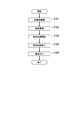
- FIG. 2 is a flow chart showing the method for processing the substrate W of this embodiment.
- FIG. 3A is a diagram showing a state before the substrate W is immersed in the stored treatment liquid L1.
- FIG. 3B is a diagram showing a state in which the substrate W is immersed in the stored treatment liquid L1.
- the circulation unit 160 starts circulating the processing liquid L.
- the control unit 140 opens the valve 166, the processing liquid L flows in the order of the inner tank 112, the outer tank 114, the pipe 161, and the processing liquid supply pipe 167.
- the processing liquid L supplied from the pipe 161 to the inside of the processing liquid supply pipe 167 is discharged from the processing liquid discharge port N into the stored processing liquid L1.
- the processing liquid L circulates.
- the elevating unit 126 lowers the substrate W while holding the substrate W by the main body plate 122 and the holding rod 124, so that the stored treatment liquid L1.
- the substrate W is dipped in.
- the bubble supply unit 130 starts the process of supplying bubbles into the stored treatment liquid L1.
- the control unit 140 opens the valve 154, bubbles are discharged from the bubble discharge port M of the gas supply pipe 131 into the stored treatment liquid L1.
- control unit 140 closes the valve 154 to end the bubble supply process by the bubble supply unit 130.
- step S105 the elevating unit 126 raises the substrate W while holding the substrate W by the main body plate 122 and the holding rod 124, thereby pulling the substrate W out of the stored treatment liquid L1. As a result, the processing on the substrate W is completed.
- the substrate processing apparatus 100 includes a pipe group G1.
- the pipe group G1 includes a gas supply pipe 131 and a pair of processing liquid supply pipes 167.
- a plurality of pipe groups G1 are provided. Specifically, two pipe groups G1 are provided.
- the two pipe groups G1 are arranged symmetrically about the virtual center line CL.
- the virtual center line CL is a virtual line that passes through the center of the inner tank 112 and is parallel to the Z axis.
- FIG. 4 is a view of the pipe group G1 viewed from the Z-axis direction.
- the gas supply pipe 131 and the processing liquid supply pipe 167 are arranged at the bottom portion 12 a (see FIG. 5) of the inner tank 112.
- the gas supply pipe 131 and the processing liquid supply pipe 167 are located below the substrate W immersed in the stored processing liquid L1.
- Each of the gas supply pipe 131 and the processing liquid supply pipe 167 extends along the Y-axis direction.
- a plurality of bubble outlets M are formed in the gas supply pipe 131.
- the plurality of bubble discharge ports M are arranged along the Y-axis direction.
- the inner diameter of the gas supply pipe 131 is, for example, about 1 mm or less.
- the inner diameter of the bubble discharge port M is, for example, about 5 mm or less.
- a plurality of processing liquid discharge ports N are formed in the processing liquid supply pipe 167.
- the plurality of processing liquid discharge ports N are arranged along the Y-axis direction.
- the inner diameter of the processing liquid supply pipe 167 is, for example, about 30 mm or less.
- the inner diameter of the processing liquid discharge port N is, for example, about 2 mm or less.
- the gas supply pipe 131 and the pair of processing liquid supply pipes 167 are arranged in parallel with each other.
- the gas supply pipe 131 and the pair of processing liquid supply pipes 167 are arranged side by side along the X-axis direction.
- the gas supply pipe 131 is arranged between the pair of processing liquid supply pipes 167.
- the pair of processing liquid supply pipes 167 are arranged so as to sandwich the gas supply pipe 131.
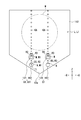
- FIG. 5 is a diagram showing a first example of the positional relationship between the bubble discharge port M and the treatment liquid discharge port N.
- a pair of processing liquid supply pipes 167 is provided with a processing liquid discharge port N1.
- the treatment liquid discharge port N1 is arranged on the side of the treatment liquid supply pipe 167 where the bubble discharge port M1 is located.
- the gas supply pipe 131 is provided with a bubble discharge port M1.
- the bubble discharge port M1 is arranged at the upper end of the gas supply pipe 131.
- the pair of processing liquid discharge ports N1 are arranged at a distance from each other.
- a bubble discharge port M1 is arranged between the pair of treatment liquid discharge ports N1.
- the bubble discharge port M1 is arranged on the side of the treatment liquid discharge port N1.
- the first direction D1 is a direction from the center T1 of the treatment liquid supply pipe 167 toward the gas supply pipe 131.
- the first direction D1 is a direction from the center T1 of the treatment liquid supply pipe 167 toward the bubble discharge port M1 of the gas supply pipe 131.
- the center T1 of the treatment liquid supply pipe 167 is formed by cutting the place where the treatment liquid discharge port N1 is located in the treatment liquid supply pipe 167 in a direction perpendicular to the extending direction (Y-axis direction) of the treatment liquid supply pipe 167. It is the center of the cross section of the processing liquid supply pipe 167 that is sometimes formed.
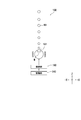
- FIG. 6A is a first schematic diagram showing the principle of discharge of the bubbles KA from the bubble outlet M1.
- FIG. 6B is a second schematic diagram showing the principle of discharge of the bubbles KA from the bubble outlet M1.
- FIG. 7 is a third schematic diagram showing the principle of discharge of the bubbles KA from the bubble discharge port M1.
- each of the pair of processing liquid discharge ports N1 opens in the first direction D1 and thus discharges the processing liquid L in the first direction D1.
- the first liquid flow R1 of the stored treatment liquid L1 is generated from each of the pair of treatment liquid discharge ports N1 in the first direction D1.
- the first liquid flow R1 flows toward the bubble outlet M1 and then flows around the bubble outlet M1.
- a raised portion KI of the gas K is generated in the stored treatment liquid L1.
- the raised portion KI is a portion of the gas K supplied to the gas supply pipe 131, which is raised from the bubble discharge port M1 into the stored treatment liquid L1.
- the first liquid flow R1 flows around the raised portion KI.
- the raised portion KI is located between the pair of first liquid flows R1.
- the raised portion KI receives the pressure of the first liquid flow R1 flowing around the bubble outlet M1. As a result, the raised portion KI is easily sheared (separated) from the gas K existing inside the gas supply pipe 131.
- the pressure due to the flow of the first liquid flow R1 is the first example of the shearing force of the present invention.
- the circulation unit 160 discharges the treatment liquid L from the treatment liquid discharge port N1 of the treatment liquid supply pipe 167 to store the treatment liquid L in the bubble supply unit 130.
- a first liquid flow R1 of the processing liquid L1 is generated. Therefore, as shown in FIG. 6B, the pressure of the first liquid flow R1 can be applied to the rising portion KI that is growing. As a result, the growing raised portion KI can be sheared at an early stage, so that the bubble KA can be prevented from becoming large.
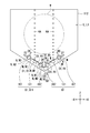
- FIG. 8 is a diagram showing a second example of the positional relationship between the bubble discharge port M and the treatment liquid discharge port N.
- the second embodiment is different from the first embodiment in the opening direction of the processing liquid discharge port N1.
- the differences from the first embodiment will be mainly described below. Further, the description will be given focusing on the pipe group G11.
- the bubble discharge port M1 is arranged on the side of the treatment liquid discharge port N1 when viewed from the Z-axis direction.
- Each of the pair of processing liquid discharge ports N1 is arranged on the lower end side of the processing liquid supply pipe 167.
- Each of the pair of processing liquid discharge ports N1 opens in the second direction D2.
- the second direction D2 is a direction from the center T1 of the treatment liquid supply pipe 167 toward the bottom portion 12a of the inner tank 112, after being reflected by the bottom portion 12a of the inner tank 112, toward the gas supply pipe 131.
- the second liquid flow R2 is generated in the second direction D2 so that the second liquid flow R2 moves toward the bottom portion 12a of the inner tank 112, reflects at the bottom portion 12a of the inner tank 112, and then heads toward the gas supply pipe 131.
- the second liquid flow R2 reaching the gas supply pipe 131 flows along the outer circumference of the gas supply pipe 131. Then, the second liquid flow R2 flows around the bubble discharge port M1 and then passes through the gas supply pipe 131.
- the second liquid flow R2 flowing around the bubble discharge port M1 applies a pressure due to the flow of the second liquid flow R2 to the raised portion KI of the gas K (see FIG. 6B). Therefore, the pressure of the second liquid flow R2 can early shear the growing ridge KI. As a result, it is possible to prevent the bubble KA from increasing.
- the pressure due to the flow of the second liquid flow R2 is the second example of the shearing force of the present invention.
- FIG. 9 is a diagram showing a third example of the positional relationship between the bubble discharge port M and the treatment liquid discharge port N.
- the third embodiment differs from the first embodiment in the position of the processing liquid supply pipe 167 with respect to the gas supply pipe 131.
- the differences from the first embodiment will be mainly described below. Further, the description will be given focusing on the pipe group G11.
- the pipe group G1 includes one gas supply pipe 131 and one processing liquid supply pipe 167.
- the processing liquid supply pipe 167 is arranged below the gas supply pipe 131.
- the processing liquid discharge port N1 is arranged below the bubble discharge port M1.
- the processing liquid discharge port N1 is arranged on the upper end side of the processing liquid supply pipe 167.
- the processing liquid discharge port N1 opens in the third direction D3.
- the third direction D3 is a direction from the center T1 of the treatment liquid supply pipe 167 toward the gas supply pipe 131. In the third embodiment, the third direction D3 is the upward direction.
- the processing liquid discharge port N1 opens in the third direction D3, the processing liquid L is discharged in the third direction D3.
- the third liquid flow R3 of the stored processing liquid L1 is generated from the processing liquid discharge port N1 toward the third direction D3.
- the third liquid flow R3 is directed toward the gas supply pipe 131 by being generated in the third direction D3.
- the third liquid flow R3 that has reached the gas supply pipe 131 flows along the outer periphery of the gas supply pipe 131. Then, the third liquid flow R3 flows around the bubble discharge port M1 and then passes through the gas supply pipe 131.
- the third liquid flow R3 reaches the gas supply pipe 131, the third liquid flow R3 separates into a pair of third liquid flows R3, and the pair of third liquid flows R3 sandwiches the gas supply pipe 131 and the outer circumference of the gas supply pipe 131. Flowing along.
- the third liquid flow R3 flowing around the bubble discharge port M1 applies pressure to the raised portion KI of the gas K (see FIG. 6B) due to the flow of the third liquid flow R3. Therefore, the pressure of the third liquid flow R3 can early shear the growing ridge KI. As a result, it is possible to prevent the bubble KA from increasing.
- the pressure due to the flow of the third liquid flow R3 is the third example of the shearing force of the present invention.
- FIG. 10 is a diagram showing a fourth example of the positional relationship between the bubble discharge port M and the treatment liquid discharge port N.
- the fourth embodiment is different from the first embodiment in the position of the processing liquid supply pipe 167 with respect to the gas supply pipe 131.
- the differences from the first embodiment will be mainly described below. Further, the description will be given focusing on the pipe group G11.
- the pair of processing liquid supply pipes 167 are arranged below the gas supply pipe 131 and spaced from each other.
- the bubble discharge port M1 is arranged on the side of the treatment liquid discharge port N1 when viewed from the Z-axis direction.
- Each of the pair of processing liquid discharge ports N1 is arranged on the upper end side of the processing liquid supply pipe 167.
- the processing liquid discharge port N1 opens in the fourth direction D4.
- the fourth direction D4 is a direction from the center T1 of the treatment liquid supply pipe 167 toward the gas supply pipe 131.
- the fourth direction D4 is an obliquely upper direction.
- the fourth liquid flow R4 is directed toward the gas supply pipe 131 by being generated in the fourth direction D4.
- the fourth liquid flow R4 that has reached the gas supply pipe 131 flows along the outer periphery of the gas supply pipe 131. Then, the fourth liquid flow R4 flows around the bubble discharge port M1 and then passes through the gas supply pipe 131.
- the fourth liquid flow R4 flowing around the bubble outlet M1 applies pressure to the raised portion KI of the gas K (see FIG. 6B) by the flow of the fourth liquid flow R4. Therefore, the pressure of the fourth liquid flow R4 can early shear the growing raised portion KI. As a result, it is possible to prevent the bubble KA from increasing.
- the pressure due to the flow of the fourth liquid flow R4 is the fourth example of the shearing force of the present invention.
- FIG. 11 is a diagram showing a fifth example of the positional relationship between the bubble discharge port M and the treatment liquid discharge port N.
- the fifth embodiment is different from the first embodiment in that the processing liquid L is discharged from the processing liquid supply pipe 167 in a plurality of directions.
- the differences from the first embodiment will be mainly described below. Further, the description will be given focusing on the pipe group G11.
- each of the pair of processing liquid supply pipes 167 has a plurality of processing liquid discharge ports N formed therein.
- three processing liquid discharge ports N are formed in each of the pair of processing liquid supply pipes 167.
- the three processing liquid discharge ports N are composed of a processing liquid discharge port N1, a processing liquid discharge port N2, and a processing liquid discharge port N3.
- the processing liquid discharge port N1 corresponds to the processing liquid discharge port N1 shown in FIG. 5 and opens in the first direction D1. As a result, since the first liquid flow R1 is generated by the processing liquid discharge port N1, the same effect as that of the first embodiment is achieved.
- the processing liquid discharge port N2 opens in a sixth direction D6 different from the first direction D1 to generate a liquid flow of the stored processing liquid L1 from the processing liquid discharge port N2 toward the sixth direction D6. ..
- the processing liquid discharge port N3 opens in a seventh direction D7 different from the first direction D1 and the sixth direction D6, so that the stored processing liquid L1 flows from the processing liquid discharge port N3 toward the seventh direction D7. Generate a liquid stream.
- the seventh direction D7 is a direction symmetrical to the first direction D1 with the sixth direction D6 as the center.
- FIG. 12 is a schematic diagram showing an example of a configuration for applying a shearing force to the raised portion KI of the gas K.
- the sixth embodiment differs from the first embodiment in that a shear force is applied to the raised portion KI of the gas K by moving the bubble discharge port M without using the liquid flow of the stored treatment liquid L1.
- the differences from the first embodiment will be mainly described below.
- the substrate processing apparatus 100 further includes a moving unit 190.
- the moving unit 190 moves the gas supply pipe 131 with respect to the inner tank 112 (see FIG. 1).
- the moving unit 190 includes, for example, a motor.
- the moving unit 190 vibrates the gas supply pipe 131, for example.
- the moving unit 190 is controlled by the control unit 140.
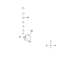
- FIG. 13A is a fourth schematic diagram showing the principle of discharge of the bubble KA from the bubble discharge port M1.
- FIG. 13B is a fifth schematic diagram showing the principle of discharge of the bubbles KA from the bubble outlet M1.
- the moving portion 190 vibrates the gas supply pipe 131, so that the raised portion KI of the gas K vibrates.
- the raised portion KI is easily sheared by the gas K existing inside the gas supply pipe 131.
- the vibration applied to the gas supply pipe 131 is the fifth example of the shearing force of the present invention.
- the moving unit 190 vibrates the gas supply pipe 131. Therefore, it is possible to apply vibration to the growing raised portion KI. As a result, the growing raised portion KI can be sheared at an early stage, so that the bubble KA can be prevented from becoming large.
- the moving unit 190 may vibrate the gas supply pipe 131 by applying ultrasonic waves to the gas supply pipe 131.
- the moving unit 190 may move the gas supply pipe 131 in parallel.
- the raised portion KI projects from the gas supply pipe 131 into the stored treatment liquid L1, so that the pressure is applied from the stored treatment liquid L1 in the direction opposite to the moving direction of the gas supply pipe 131.
- the rising portion KI that is growing can be sheared at an early stage by the pressure from the stored treatment liquid L1, so that the bubble KA can be prevented from becoming large.
- the pressure that the raised portion KI receives from the stored treatment liquid L1 when the gas supply pipe 131 moves in parallel is the sixth example of the shearing force of the present invention.
- the direction in which the gas supply pipe 131 is moved in parallel is not particularly limited.
- the moving unit 190 may rotate the gas supply pipe 131 around the axis of the gas supply pipe 131.
- the raised portion KI protrudes from the gas supply pipe 131 into the stored treatment liquid L1, so that the pressure is applied from the stored treatment liquid L1 in the direction opposite to the rotation direction of the gas supply pipe 131. receive.
- the rising portion KI that is growing can be sheared at an early stage by the pressure from the stored treatment liquid L1, so that the bubble KA can be prevented from becoming large.
- the pressure that the raised portion KI receives from the stored treatment liquid L1 when the gas supply pipe 131 rotates is the seventh example of the shearing force of the present invention.
- FIG. 1 to 13B The embodiment of the present invention has been described above with reference to the drawings (FIGS. 1 to 13B).
- the present invention is not limited to the above-described embodiments, and can be carried out in various modes without departing from the gist thereof (for example, (1) to (5)).
- various inventions can be formed by appropriately combining the plurality of constituent elements disclosed in the above-described embodiments.
- some components may be deleted from all the components shown in the embodiment.
- the drawings mainly show respective constituent elements, and the number of the constituent elements shown in the drawings may be different from the actual one due to the convenience of drawing.
- each component shown in the above-described embodiment is an example and is not particularly limited, and various modifications can be made within a range that does not substantially deviate from the effect of the present invention.
- control unit 140 adjusts the opening degree of the pipe 161 by the adjusting valve 165, so that the first liquid flow R1 to the fourth liquid flow R1 to the fourth liquid flow given to the gas supply pipe 131.
- the magnitude of each pressure of the liquid flow R4 is controlled.
- the control unit 140 may make the magnitudes of the pressures of the first liquid flow R1 to the fourth liquid flow R4 constant by making the opening of the pipe 161 constant. Further, the control unit 140 may periodically change the magnitude of each pressure of the first liquid flow R1 to the fourth liquid flow R4 by changing the opening degree of the pipe 161 at predetermined time intervals. That is, the control unit 140 may increase or decrease the magnitude of the pressure of each of the first liquid flow R1 to the fourth liquid flow R4.
- the portion of the gas supply pipe 131 (see FIG. 4) where the bubble outlet M is formed is subjected to a hydrophobic treatment, for example, by being coated with fluorine. May be.
- a hydrophobic treatment for example, by being coated with fluorine. May be.
- the hydrophobic treatment may be performed not only on the portion of the gas supply pipe 131 where the bubble outlet M is formed, but also on the entire gas supply pipe 131.
- the bubble discharge port M opens upward.
- the present invention is not limited to this.
- FIG. 14 is a diagram showing a first modification of the bubble outlet M.
- the bubble discharge port M opens laterally.
- the horizontal direction is a direction parallel to the horizontal direction (X-axis direction). Therefore, when the raised portion KI of the gas K tries to float from the bubble outlet M, it contacts the upper end of the bubble outlet M, so that the upper end of the bubble outlet M can effectively shear the raised portion KI. it can. As a result, it is possible to prevent the bubble KA from increasing.
- FIG. 15 is a diagram showing a second modification of the bubble discharge port M.
- the opening area of the bubble discharge port M becomes smaller toward the outside of the gas supply pipe 131.
- the 2nd modification of the bubble discharge port M is demonstrated in detail.
- the gas supply pipe 131 has an inner surface 131b and an outer surface 131c.
- the inner surface 131b faces the inside 131a of the gas supply pipe 131.
- the outer surface 131c faces the inside of the gas supply pipe 131.
- the bubble outlet M has an outer opening Ma and an inner opening Mb.
- the outer opening Ma is formed on the outer surface 131c.
- the inner opening Mb is formed in the inner surface 131b.
- the inner opening Mb communicates with the outer opening Ma.
- the opening area V1 of the outer opening Ma is smaller than the opening area V2 of the inner opening Mb (V1 ⁇ V2).
- the opening area is the area of the cross section of the bubble outlet M perpendicular to the direction from the inner opening Mb to the outer opening Ma.
- the opening area of the bubble discharge port M may be gradually reduced from the inner opening Mb toward the outer opening Ma. Further, the opening area of the bubble discharge port M may be gradually reduced from the inner opening Mb toward the outer opening Ma.
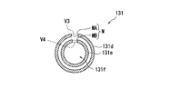
- FIG. 16 is a diagram showing a modified example of the gas supply pipe 131.
- a modified example of the gas supply pipe 131 shown in FIG. 16 has a double pipe structure. Below, the modification of the gas supply pipe 131 is demonstrated in detail.
- the gas supply pipe 131 has an outer pipe 131d and an inner pipe 131e.
- Each of the outer pipe 131d and the inner pipe 131e is a tubular member.
- the outer diameter of the outer pipe 131d is larger than the outer diameter of the inner pipe 131e.
- the inner pipe 131e is arranged inside the outer pipe 131d.
- the gas K flows through the inside 131f of the inner pipe 131e.
- the bubble discharge port M has a first opening MA and a second opening MB.
- the first opening MA is formed in the outer pipe 131d and connects the inside and the outside of the outer pipe 131d.
- the second opening MB is formed in the inner pipe 131e and connects the inside 131f and the outside of the inner pipe 131e.
- the first opening MA and the second opening MB open in the same direction as each other.
- the opening area V3 of the first opening MA is substantially the same as the opening area V4 of the second opening MB (V3 ⁇ V4).
- double pressure can be applied to the raised portion KI (see FIG. 6B) by the first opening MA and the second opening MB, so that the growth of the raised portion KI can be suppressed.
- the opening area V3 of the first opening MA may be smaller than the opening area V4 of the second opening MB (V3 ⁇ V4).
- the gas supply pipe 131 which is the bubble supply unit 130, contains quartz.
- the present invention is not limited to this.
- the gas supply pipe 131 may include PEEK (polyether ether ketone). That is, in the first to sixth embodiments, the PEEK gas supply pipe 131 may be used.
- the gas supply pipe 131 is immersed in the processing liquid L (phosphoric acid aqueous solution) at a high temperature (for example, about 160° C.). (See Figure 1).
- the gas supply pipe 131 is made of quartz and the gas supply pipe 131 is used for a long time (for example, from half a year to one year), the gas supply pipe 131 may be immersed in the high-temperature treatment liquid L for a long time. Therefore, the diameter of the bubble discharge port M may increase.
- the bubbles KA are emitted from the bubble emission port M having an enlarged diameter, so that the emission of the bubbles KA from the plurality of bubble emission ports M varies, and the substrate processing apparatus.
- the processing capability of the substrate W by 100 may decrease. Therefore, the gas supply pipe 131 made of quartz has been replaced in about half a year to one year.
- the present inventor suppresses the expansion of the diameter of the bubble outlet M and extends the replacement life of the gas supply pipe 131. It was decided to use a resin that can withstand the period. Further, the inventor of the present application listed PEEK, PFA (tetrafluoroethylene-perfluoroalkyl vinyl ether copolymer), and PTFE (polytetrafluoroethylene) as candidates as the resin for the gas supply pipe 131. .. Then, the inventor of the present application has verified which of PEEK, PFA, and PTFE is most suitable as a material for the gas supply pipe 131.
- the inner diameter of the bubble discharge port M is 0.2 mm.
- the outer diameter of the gas supply pipe 131 used in the verification is 8 mm, and the inner diameter is 4 mm.
- the length of the gas supply pipe 131 used in the verification is 400 mm.
- the dimensions of the gas supply pipe 131 are not limited to these, and for example, the outer diameter of the gas supply pipe 131 may be 6 mm or more and 12 mm or less, and the inner diameter may be 2 mm or more and 10 mm or less.
- the inner diameter of the treatment liquid discharge port N is, for example, 1 mm. From the treatment liquid discharge port N, the treatment liquid L is discharged instead of the bubbles KA. Therefore, the treatment liquid supply pipe 167 does not have the problem caused by the variation of the bubbles KA like the gas supply pipe 131. Therefore, the replacement life (about several years) of the treatment liquid supply pipe 167 is equal to that of the gas supply pipe 131. It is longer than the life (half a year to a year). Therefore, since the gas supply pipe 131 is replaced more frequently than the processing liquid supply pipe 167, the inventor of the present application has an object to extend the replacement life of the gas supply pipe 131. Then, the present inventor devised a material of the gas supply pipe 131 in order to solve the problem.
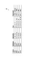
- FIG. 17 is Table H showing the comparison results of PEEK, PFA, and PTFE. Note that, in Table H of FIG. 17, information regarding quartz is also described as a reference.
- PEEK has the lowest linear expansion coefficient among various resin materials (PEEK, PFA, and PTFE). Therefore, among the various gas supply pipes, the PEEK gas supply pipe 131 is most resistant to thermal expansion, which is advantageous in that positional deviation due to thermal expansion is most unlikely to occur in the inner tank 112.
- the PEEK gas supply pipe 131 is advantageous in that it is the most difficult to deform even when pressure is applied from the outside.
- PEEK has the highest heat distortion temperature among various resin materials. Therefore, among the various gas supply pipes, the PEEK gas supply pipe 131 is advantageous in that it is most resistant to thermal deformation.
- the inventor of the present application has discovered that the wettability (contact angle) of the surface of the gas supply pipe 131 affects the breakage of the bubbles KA discharged from the bubble discharge port M. Specifically, the inventor of the present application is able to discharge the small bubbles KA from the bubble outlet M as the wettability of the surface of the gas supply pipe 131 becomes smaller (the contact angle becomes larger) so that the bubbles KA are broken. I have found Further, the inventor of the present application has the smallest wettability of the surface of the gas supply pipe 131 made of PEEK among the various gas supply pipes, and thus the small bubbles KA are effective from the bubble discharge port M of the gas supply pipe 131 made of PEEK. It has been discovered that it can be released.
- the inventor of the present application comprehensively judges the viewpoints of the linear expansion coefficient, the hardness, the heat distortion temperature, and the wettability described above, and among the various gas supply pipes, gas supply made of PEEK is supplied. It has been determined that the use of tube 131 is most advantageous. As a result, in the substrate processing apparatus 100, the PEEK gas supply pipe 131 is used.
- the durability of the gas supply pipe 131 with respect to the processing liquid L can be improved, and the replacement life of the gas supply pipe 131 can be improved. It can be postponed.
- the present invention can be used in the field of substrate processing apparatuses and substrate processing methods.
Landscapes
- Weting (AREA)
- Cleaning Or Drying Semiconductors (AREA)
- Manufacturing Of Printed Circuit Boards (AREA)
Abstract
Description
図1を参照して、本発明の第1実施形態に係る基板処理装置100を説明する。図1は、本発明の第1実施形態に係る基板処理装置100の模式図である。基板処理装置100は、複数の基板Wを一括して処理する。例えば、基板処理装置100は複数の基板Wに対して一括してエッチングする。
図8を参照して、本発明の第2実施形態に係る基板処理装置100を説明する。図8は、気泡放出口Mと処理液放出口Nとの位置関係の第2例を示す図である。
図9を参照して、本発明の第3実施形態に係る基板処理装置100を説明する。図9は、気泡放出口Mと処理液放出口Nとの位置関係の第3例を示す図である。
図10を参照して、本発明の第4実施形態に係る基板処理装置100を説明する。図10は、気泡放出口Mと処理液放出口Nとの位置関係の第4例を示す図である。
図11を参照して、本発明の第5実施形態に係る基板処理装置100を説明する。図11は、気泡放出口Mと処理液放出口Nとの位置関係の第5例を示す図である。
図12~図13(b)を参照して、本発明の第6実施形態に係る基板処理装置100を説明する。図12は、気体Kの隆起部分KIに対してせん断力を付与するための構成の一例を示す模式図である。
112 内槽(貯留部)
130 気泡供給部
160 循環部(液流生成部)
KA 気泡
L 処理液
L1 貯留処理液
R1 第1液流(液流)
R2 第2液流(液流)
R3 第3液流(液流)
R4 第4液流(液流)
W 基板
Claims (13)
- 貯留部に貯留される処理液である貯留処理液に基板を浸漬して前記基板の処理を行う基板処理装置であって、
前記貯留処理液に気泡を供給する気泡供給部と、
前記気泡供給部に対して前記貯留処理液の液流を生成する液流生成部と
を備える、基板処理装置。 - 前記気泡供給部は、気体が流れる第1管部を有し、
前記第1管部には、前記貯留処理液内に配置される気泡放出口が形成され、
前記気泡放出口は、前記貯留処理液内に前記気体の気泡を放出し、
前記液流生成部は、前記気泡放出口の周辺に前記液流を生成する、請求項1に記載の基板処理装置。 - 前記第1管部のうち前記気泡放出口が形成される部分には、疎水処理が施される、請求項2に記載の基板処理装置。
- 前記液流生成部は、前記処理液が流れる第2管部を有し、
前記第2管部には、前記貯留処理液内に配置される処理液放出口が形成され、
前記処理液放出口は、前記貯留処理液内に前記第2管部を流れる前記処理液を放出することで前記液流を生成する、請求項2又は請求項3に記載の基板処理装置。 - 前記処理液放出口は、上方から見て前記気泡放出口の側方に配置される、請求項4に記載の基板処理装置。
- 前記処理液放出口は、前記気泡放出口の下方に配置される、請求項4に記載の基板処理装置。
- 前記気泡放出口は、横向きに開口する、請求項2から請求項6のいずれか1項に記載の基板処理装置。
- 前記第1管部は、
前記第1管部の内部に対向する内面と、
前記第1管部の外部に対向する外面と
を有し、
前記気泡放出口は、
前記外面に形成される外側開口と、
前記内面に形成され、前記外側開口に連通する内側開口と
を有し、
前記外側開口の開口面積の方が、前記内側開口の開口面積よりも小さい、請求項2から請求項7のいずれか1項に記載の基板処理装置。 - 貯留部に貯留される処理液である貯留処理液に基板を浸漬して前記基板の処理を行う基板処理装置であって、
前記貯留処理液に気泡を供給する気泡供給部と、
前記貯留部に対して前記気泡供給部を移動させる移動部と
を備える、基板処理装置。 - 前記気泡供給部は、気体が流れる第1管部を有し、
前記第1管部には、前記貯留処理液内に配置される気泡放出口が形成され、
前記気泡放出口は、前記貯留処理液内に前記気体の気泡を放出し、
前記移動部は、前記貯留部に対して前記第1管部を移動させる、請求項9に記載の基板処理装置。 - 前記移動部は、前記第1管部を振動させる、請求項10に記載の基板処理装置。
- 前記気泡供給部は、ポリエーテルエーテルケトンを含む、請求項1から請求項11のいずれか1項に記載の基板処理装置。
- 貯留部に貯留される処理液である貯留処理液に基板を浸漬して前記基板の処理を行う基板処理方法であって、
管部に形成される気泡放出口を前記貯留処理液内に配置する工程と、
前記管部に気体を流す工程と、
前記気体のうち前記気泡放出口から前記貯留処理液内に隆起する隆起部分を、前記管部の内部に存在する前記気体からせん断するためのせん断力を付与する工程と
を備える、基板処理方法。
Priority Applications (5)
| Application Number | Priority Date | Filing Date | Title |
|---|---|---|---|
| KR1020217028839A KR102689164B1 (ko) | 2019-02-20 | 2020-02-19 | 기판 처리 장치, 및 기판 처리 방법 |
| CN202510624211.0A CN120497170A (zh) | 2019-02-20 | 2020-02-19 | 基板处理装置及基板处理方法 |
| CN202080014920.2A CN113490999B (zh) | 2019-02-20 | 2020-02-19 | 基板处理装置及基板处理方法 |
| KR1020247024291A KR102832931B1 (ko) | 2019-02-20 | 2020-02-19 | 기판 처리 장치, 및 기판 처리 방법 |
| CN202510401970.0A CN120261342A (zh) | 2019-02-20 | 2020-02-19 | 基板处理装置及基板处理方法 |
Applications Claiming Priority (4)
| Application Number | Priority Date | Filing Date | Title |
|---|---|---|---|
| JP2019028413 | 2019-02-20 | ||
| JP2019-028413 | 2019-02-20 | ||
| JP2020024138A JP7368264B2 (ja) | 2019-02-20 | 2020-02-17 | 基板処理装置、及び基板処理方法 |
| JP2020-024138 | 2020-02-17 |
Publications (1)
| Publication Number | Publication Date |
|---|---|
| WO2020171124A1 true WO2020171124A1 (ja) | 2020-08-27 |
Family
ID=72144922
Family Applications (1)
| Application Number | Title | Priority Date | Filing Date |
|---|---|---|---|
| PCT/JP2020/006555 Ceased WO2020171124A1 (ja) | 2019-02-20 | 2020-02-19 | 基板処理装置、及び基板処理方法 |
Country Status (5)
| Country | Link |
|---|---|
| JP (1) | JP7633347B2 (ja) |
| KR (1) | KR102832931B1 (ja) |
| CN (2) | CN120497170A (ja) |
| TW (2) | TWI750592B (ja) |
| WO (1) | WO2020171124A1 (ja) |
Cited By (3)
| Publication number | Priority date | Publication date | Assignee | Title |
|---|---|---|---|---|
| CN114446823A (zh) * | 2020-10-30 | 2022-05-06 | 株式会社斯库林集团 | 基板处理装置及基板处理方法 |
| TWI853428B (zh) * | 2022-02-01 | 2024-08-21 | 日商斯庫林集團股份有限公司 | 基板處理裝置及基板處理方法 |
| TWI905546B (zh) * | 2022-09-22 | 2025-11-21 | 日商斯庫林集團股份有限公司 | 基板處理裝置及基板處理方法 |
Citations (5)
| Publication number | Priority date | Publication date | Assignee | Title |
|---|---|---|---|---|
| JPH0969510A (ja) * | 1995-08-30 | 1997-03-11 | Shin Etsu Handotai Co Ltd | エッチング装置 |
| JP2004146545A (ja) * | 2002-10-24 | 2004-05-20 | Univ Shizuoka | シリコン基板のエッチング方法とシリコン基板のエッチング装置 |
| JP2004356299A (ja) * | 2003-05-28 | 2004-12-16 | Tokyo Electron Ltd | 液処理装置およびその接液部に用いられる部品ならびにその部品の製造方法 |
| JP2006344792A (ja) * | 2005-06-09 | 2006-12-21 | Toshiba Corp | 半導体ウェハ処理装置及び半導体装置の製造方法 |
| JP2018174257A (ja) * | 2017-03-31 | 2018-11-08 | 東京エレクトロン株式会社 | 基板液処理装置 |
Family Cites Families (11)
| Publication number | Priority date | Publication date | Assignee | Title |
|---|---|---|---|---|
| JPH11204476A (ja) * | 1998-01-13 | 1999-07-30 | Tokyo Electron Ltd | 洗浄処理装置及び洗浄処理方法 |
| JP2006093356A (ja) | 2004-09-22 | 2006-04-06 | Sekisui Chem Co Ltd | オゾン水噴射チューブノズル |
| JP4869957B2 (ja) | 2006-03-22 | 2012-02-08 | 大日本スクリーン製造株式会社 | 基板処理装置 |
| JP4532580B2 (ja) | 2008-08-20 | 2010-08-25 | 株式会社カイジョー | 超音波洗浄装置 |
| JP5829458B2 (ja) * | 2011-08-25 | 2015-12-09 | 株式会社Screenホールディングス | 基板処理装置 |
| JP6116948B2 (ja) * | 2013-03-14 | 2017-04-19 | 株式会社Screenホールディングス | 基板処理装置及びその洗浄方法 |
| JP2015040279A (ja) | 2013-08-23 | 2015-03-02 | 三井・デュポンフロロケミカル株式会社 | 半導体製造装置に用いられるフッ素樹脂成形品の洗浄方法 |
| JP6356727B2 (ja) | 2016-05-27 | 2018-07-11 | 株式会社Screenホールディングス | 基板処理装置 |
| JP6693846B2 (ja) * | 2016-09-28 | 2020-05-13 | 株式会社Screenホールディングス | 基板処理装置および基板処理方法 |
| JP6895295B2 (ja) | 2017-03-31 | 2021-06-30 | 東京エレクトロン株式会社 | 基板液処理装置、基板液処理方法及び記憶媒体 |
| JP7190912B2 (ja) | 2019-01-10 | 2022-12-16 | 東京エレクトロン株式会社 | 基板処理装置 |
-
2020
- 2020-02-19 TW TW109105310A patent/TWI750592B/zh active
- 2020-02-19 CN CN202510624211.0A patent/CN120497170A/zh active Pending
- 2020-02-19 TW TW110142669A patent/TWI804053B/zh active
- 2020-02-19 CN CN202510401970.0A patent/CN120261342A/zh active Pending
- 2020-02-19 WO PCT/JP2020/006555 patent/WO2020171124A1/ja not_active Ceased
- 2020-02-19 KR KR1020247024291A patent/KR102832931B1/ko active Active
-
2023
- 2023-10-12 JP JP2023176538A patent/JP7633347B2/ja active Active
Patent Citations (5)
| Publication number | Priority date | Publication date | Assignee | Title |
|---|---|---|---|---|
| JPH0969510A (ja) * | 1995-08-30 | 1997-03-11 | Shin Etsu Handotai Co Ltd | エッチング装置 |
| JP2004146545A (ja) * | 2002-10-24 | 2004-05-20 | Univ Shizuoka | シリコン基板のエッチング方法とシリコン基板のエッチング装置 |
| JP2004356299A (ja) * | 2003-05-28 | 2004-12-16 | Tokyo Electron Ltd | 液処理装置およびその接液部に用いられる部品ならびにその部品の製造方法 |
| JP2006344792A (ja) * | 2005-06-09 | 2006-12-21 | Toshiba Corp | 半導体ウェハ処理装置及び半導体装置の製造方法 |
| JP2018174257A (ja) * | 2017-03-31 | 2018-11-08 | 東京エレクトロン株式会社 | 基板液処理装置 |
Cited By (4)
| Publication number | Priority date | Publication date | Assignee | Title |
|---|---|---|---|---|
| CN114446823A (zh) * | 2020-10-30 | 2022-05-06 | 株式会社斯库林集团 | 基板处理装置及基板处理方法 |
| TWI853428B (zh) * | 2022-02-01 | 2024-08-21 | 日商斯庫林集團股份有限公司 | 基板處理裝置及基板處理方法 |
| US12500099B2 (en) | 2022-02-01 | 2025-12-16 | SCREEN Holdings Co., Ltd. | Substrate processing apparatus and substrate processing method |
| TWI905546B (zh) * | 2022-09-22 | 2025-11-21 | 日商斯庫林集團股份有限公司 | 基板處理裝置及基板處理方法 |
Also Published As
| Publication number | Publication date |
|---|---|
| CN120497170A (zh) | 2025-08-15 |
| KR102832931B1 (ko) | 2025-07-10 |
| TW202040720A (zh) | 2020-11-01 |
| CN120261342A (zh) | 2025-07-04 |
| KR20240115935A (ko) | 2024-07-26 |
| TW202215576A (zh) | 2022-04-16 |
| TWI804053B (zh) | 2023-06-01 |
| TWI750592B (zh) | 2021-12-21 |
| JP7633347B2 (ja) | 2025-02-19 |
| JP2023171597A (ja) | 2023-12-01 |
Similar Documents
| Publication | Publication Date | Title |
|---|---|---|
| JP7368264B2 (ja) | 基板処理装置、及び基板処理方法 | |
| US11699601B2 (en) | Substrate processing method | |
| JP7633347B2 (ja) | 基板処理装置 | |
| US11164750B2 (en) | Substrate processing device and substrate processing method | |
| US8449684B2 (en) | Substrate cleaning method, substrate cleaning system and program storage medium | |
| US12599925B2 (en) | Substrate processing apparatus and substrate processing method | |
| JP2019129243A (ja) | 基板処理装置および基板処理方法 | |
| US20220139733A1 (en) | Substrate processing apparatus and substrate processing method | |
| JP7454986B2 (ja) | 基板処理方法および基板処理装置 | |
| TWI919682B (zh) | 基板處理裝置 | |
| JP7863145B2 (ja) | 基板処理装置および基板処理方法 | |
| US20260077390A1 (en) | Substrate processing device and substrate processing method | |
| TW202544912A (zh) | 基板處理裝置 | |
| TW202612073A (zh) | 基板處理裝置及基板處理方法 | |
| JP2024004752A (ja) | 基板処理方法、及び基板処理装置 |
Legal Events
| Date | Code | Title | Description |
|---|---|---|---|
| 121 | Ep: the epo has been informed by wipo that ep was designated in this application |
Ref document number: 20758450 Country of ref document: EP Kind code of ref document: A1 |
|
| NENP | Non-entry into the national phase |
Ref country code: DE |
|
| ENP | Entry into the national phase |
Ref document number: 20217028839 Country of ref document: KR Kind code of ref document: A |
|
| 122 | Ep: pct application non-entry in european phase |
Ref document number: 20758450 Country of ref document: EP Kind code of ref document: A1 |
|
| WWG | Wipo information: grant in national office |
Ref document number: 202080014920.2 Country of ref document: CN |