WO2020170641A1 - エンジンのegr装置 - Google Patents
エンジンのegr装置 Download PDFInfo
- Publication number
- WO2020170641A1 WO2020170641A1 PCT/JP2020/000547 JP2020000547W WO2020170641A1 WO 2020170641 A1 WO2020170641 A1 WO 2020170641A1 JP 2020000547 W JP2020000547 W JP 2020000547W WO 2020170641 A1 WO2020170641 A1 WO 2020170641A1
- Authority
- WO
- WIPO (PCT)
- Prior art keywords
- egr
- intake pressure
- engine
- valve
- egr valve
- Prior art date
- Legal status (The legal status is an assumption and is not a legal conclusion. Google has not performed a legal analysis and makes no representation as to the accuracy of the status listed.)
- Ceased
Links
Images



Classifications
-
- F—MECHANICAL ENGINEERING; LIGHTING; HEATING; WEAPONS; BLASTING
- F02—COMBUSTION ENGINES; HOT-GAS OR COMBUSTION-PRODUCT ENGINE PLANTS
- F02M—SUPPLYING COMBUSTION ENGINES IN GENERAL WITH COMBUSTIBLE MIXTURES OR CONSTITUENTS THEREOF
- F02M26/00—Engine-pertinent apparatus for adding exhaust gases to combustion-air, main fuel or fuel-air mixture, e.g. by exhaust gas recirculation [EGR] systems
- F02M26/49—Detecting, diagnosing or indicating an abnormal function of the EGR system
-
- F—MECHANICAL ENGINEERING; LIGHTING; HEATING; WEAPONS; BLASTING
- F02—COMBUSTION ENGINES; HOT-GAS OR COMBUSTION-PRODUCT ENGINE PLANTS
- F02D—CONTROLLING COMBUSTION ENGINES
- F02D41/00—Electrical control of supply of combustible mixture or its constituents
- F02D41/0002—Controlling intake air
-
- F—MECHANICAL ENGINEERING; LIGHTING; HEATING; WEAPONS; BLASTING
- F02—COMBUSTION ENGINES; HOT-GAS OR COMBUSTION-PRODUCT ENGINE PLANTS
- F02D—CONTROLLING COMBUSTION ENGINES
- F02D41/00—Electrical control of supply of combustible mixture or its constituents
- F02D41/22—Safety or indicating devices for abnormal conditions
- F02D41/221—Safety or indicating devices for abnormal conditions relating to the failure of actuators or electrically driven elements
-
- F—MECHANICAL ENGINEERING; LIGHTING; HEATING; WEAPONS; BLASTING
- F02—COMBUSTION ENGINES; HOT-GAS OR COMBUSTION-PRODUCT ENGINE PLANTS
- F02M—SUPPLYING COMBUSTION ENGINES IN GENERAL WITH COMBUSTIBLE MIXTURES OR CONSTITUENTS THEREOF
- F02M26/00—Engine-pertinent apparatus for adding exhaust gases to combustion-air, main fuel or fuel-air mixture, e.g. by exhaust gas recirculation [EGR] systems
- F02M26/13—Arrangement or layout of EGR passages, e.g. in relation to specific engine parts or for incorporation of accessories
- F02M26/14—Arrangement or layout of EGR passages, e.g. in relation to specific engine parts or for incorporation of accessories in relation to the exhaust system
-
- F—MECHANICAL ENGINEERING; LIGHTING; HEATING; WEAPONS; BLASTING
- F02—COMBUSTION ENGINES; HOT-GAS OR COMBUSTION-PRODUCT ENGINE PLANTS
- F02M—SUPPLYING COMBUSTION ENGINES IN GENERAL WITH COMBUSTIBLE MIXTURES OR CONSTITUENTS THEREOF
- F02M26/00—Engine-pertinent apparatus for adding exhaust gases to combustion-air, main fuel or fuel-air mixture, e.g. by exhaust gas recirculation [EGR] systems
- F02M26/13—Arrangement or layout of EGR passages, e.g. in relation to specific engine parts or for incorporation of accessories
- F02M26/17—Arrangement or layout of EGR passages, e.g. in relation to specific engine parts or for incorporation of accessories in relation to the intake system
-
- F—MECHANICAL ENGINEERING; LIGHTING; HEATING; WEAPONS; BLASTING
- F02—COMBUSTION ENGINES; HOT-GAS OR COMBUSTION-PRODUCT ENGINE PLANTS
- F02D—CONTROLLING COMBUSTION ENGINES
- F02D2200/00—Input parameters for engine control
- F02D2200/02—Input parameters for engine control the parameters being related to the engine
- F02D2200/04—Engine intake system parameters
- F02D2200/0404—Throttle position
-
- F—MECHANICAL ENGINEERING; LIGHTING; HEATING; WEAPONS; BLASTING
- F02—COMBUSTION ENGINES; HOT-GAS OR COMBUSTION-PRODUCT ENGINE PLANTS
- F02D—CONTROLLING COMBUSTION ENGINES
- F02D2200/00—Input parameters for engine control
- F02D2200/02—Input parameters for engine control the parameters being related to the engine
- F02D2200/04—Engine intake system parameters
- F02D2200/0406—Intake manifold pressure
-
- F—MECHANICAL ENGINEERING; LIGHTING; HEATING; WEAPONS; BLASTING
- F02—COMBUSTION ENGINES; HOT-GAS OR COMBUSTION-PRODUCT ENGINE PLANTS
- F02D—CONTROLLING COMBUSTION ENGINES
- F02D2200/00—Input parameters for engine control
- F02D2200/02—Input parameters for engine control the parameters being related to the engine
- F02D2200/10—Parameters related to the engine output, e.g. engine torque or engine speed
- F02D2200/1002—Output torque
-
- F—MECHANICAL ENGINEERING; LIGHTING; HEATING; WEAPONS; BLASTING
- F02—COMBUSTION ENGINES; HOT-GAS OR COMBUSTION-PRODUCT ENGINE PLANTS
- F02D—CONTROLLING COMBUSTION ENGINES
- F02D2200/00—Input parameters for engine control
- F02D2200/02—Input parameters for engine control the parameters being related to the engine
- F02D2200/10—Parameters related to the engine output, e.g. engine torque or engine speed
- F02D2200/101—Engine speed
-
- F—MECHANICAL ENGINEERING; LIGHTING; HEATING; WEAPONS; BLASTING
- F02—COMBUSTION ENGINES; HOT-GAS OR COMBUSTION-PRODUCT ENGINE PLANTS
- F02D—CONTROLLING COMBUSTION ENGINES
- F02D41/00—Electrical control of supply of combustible mixture or its constituents
- F02D41/02—Circuit arrangements for generating control signals
- F02D41/18—Circuit arrangements for generating control signals by measuring intake air flow
-
- F—MECHANICAL ENGINEERING; LIGHTING; HEATING; WEAPONS; BLASTING
- F02—COMBUSTION ENGINES; HOT-GAS OR COMBUSTION-PRODUCT ENGINE PLANTS
- F02M—SUPPLYING COMBUSTION ENGINES IN GENERAL WITH COMBUSTIBLE MIXTURES OR CONSTITUENTS THEREOF
- F02M26/00—Engine-pertinent apparatus for adding exhaust gases to combustion-air, main fuel or fuel-air mixture, e.g. by exhaust gas recirculation [EGR] systems
- F02M26/52—Systems for actuating EGR valves
- F02M26/53—Systems for actuating EGR valves using electric actuators, e.g. solenoids
- F02M26/54—Rotary actuators, e.g. step motors
-
- F—MECHANICAL ENGINEERING; LIGHTING; HEATING; WEAPONS; BLASTING
- F02—COMBUSTION ENGINES; HOT-GAS OR COMBUSTION-PRODUCT ENGINE PLANTS
- F02M—SUPPLYING COMBUSTION ENGINES IN GENERAL WITH COMBUSTIBLE MIXTURES OR CONSTITUENTS THEREOF
- F02M26/00—Engine-pertinent apparatus for adding exhaust gases to combustion-air, main fuel or fuel-air mixture, e.g. by exhaust gas recirculation [EGR] systems
- F02M26/65—Constructional details of EGR valves
- F02M26/66—Lift valves, e.g. poppet valves
Definitions
- the technique disclosed in this specification relates to an EGR device that causes a part of engine exhaust to flow as EGR gas to an intake passage through an EGR passage and recirculate to the engine, and more specifically, to an EGR valve provided in the EGR passage.
- the present invention relates to an EGR device for an engine configured to diagnose an abnormality due to stuck valve opening.
- This technology relates to a failure detection device for an engine exhaust gas recirculation device (Exhaust Gas Recirculation (EGR) device).
- the engine includes an intake passage, an exhaust passage, a fuel supply means, and an intake amount adjusting means provided in the intake passage.
- the EGR device includes an EGR passage and an electric EGR valve.
- the EGR valve includes a valve seat, a valve body, a motor, and the like. Intake pressure detecting means for detecting the intake pressure is provided in the intake passage downstream of the intake amount adjusting means. Further, the engine is provided with load detection means for detecting the engine load.
- the failure detection device determines a failure (abnormality) of the EGR device based on the intake pressure detected according to the operating state of the EGR valve when the engine is in a steady state and a predetermined determination condition is satisfied.
- a failure determination means is provided.
- the failure determination means determines the intake pressure detected according to the operating condition of the EGR valve in accordance with the predetermined determination condition when the engine is in a steady state and the predetermined determination condition is satisfied. By comparing with the intake pressure, the abnormality of the EGR valve (for example, foreign matter caught between the valve seat and the valve body) is determined.
- the predetermined determination condition it is set that the detected engine load is within a predetermined load range and the motor that constitutes the EGR valve is within a predetermined operating range.
- an abnormality of the EGR device is determined on the assumption that the engine is in a steady state and a predetermined determination condition is satisfied.
- a predetermined load range is a low engine rotation low load
- a predetermined operation range is a small opening degree of the EGR valve, which is a prerequisite for the failure determination. .. Therefore, the failure determination may be affected by various variations and disturbances (for example, tappet clearance and valve timing deviation, air density (temperature), PCV flow rate, electric load, etc.), and try to avoid these variations and disturbances.
- the determined intake pressure determined according to the predetermined determination condition may be affected by the fluctuation of the engine speed, and the abnormality cannot be accurately detected.
- the disclosed technique has been made in view of the above circumstances, and an object thereof is an abnormality due to stuck valve opening of an EGR valve without limiting a condition related to an operating state of an engine or an operating state of an EGR valve to a specific condition. It is to provide an EGR device for an engine that enables early and accurate diagnosis.
- an aspect of the present invention is that EGR gas is made to flow from an exhaust passage to an intake passage in order to recirculate a part of exhaust gas discharged from the engine to the exhaust passage as EGR gas to the engine.
- the EGR valve for adjusting the flow rate of the EGR gas in the passage, the EGR passage, the throttle valve for adjusting the intake air amount in the intake passage, and the operation of the engine acquired when the EGR valve is closed and controlled.
- An EGR device for an engine comprising: an EGR valve abnormality diagnosing means for calculating a reference intake pressure based on the state and diagnosing at least an abnormality due to sticking of an EGR valve based on the calculated reference intake pressure.
- the operating state includes the intake pressure in the intake passage downstream of the throttle valve, the engine speed, and the engine load.
- the EGR valve abnormality diagnosing means sets the reference intake pressure to the acquired engine speed and the acquired load. According to the obtained number of revolutions, the intake pressure increase margin is calculated, the calculated intake pressure increase margin is added to the calculated reference intake pressure, and the EGR valve is calculated based on the addition result and the acquired intake pressure. The purpose is to determine whether or not there is an abnormality due to stuck valve opening.
- the intake pressure increase margin calculated according to the acquired rotation speed is added to the reference intake pressure calculated according to the acquired rotation speed and the acquired load. Then, it is determined whether or not there is an abnormality due to the open valve sticking of the EGR valve, based on the addition result and the acquired intake pressure. Therefore, since the reference intake pressure is calculated according to various operating states of the engine, it is necessary to limit the operating state of the engine to a specific condition such as sonic in determining whether there is an abnormality due to the stuck open valve of the EGR valve. Moreover, it is not necessary to limit the operating state of the EGR valve to a specific condition.
- the intake pressure rise amount calculated according to the engine speed is added to the reference intake pressure, so the EGR valve is closed due to valve opening sticking.
- the amount of increase in intake pressure caused by the absence of the intake air is reflected in the determination as to whether or not there is an abnormality due to stuck valve opening.
- the EGR valve abnormality diagnosing means calculates the opening degree of the EGR valve based on the addition result and the acquired intake pressure, and the calculated EGR valve.
- the opening of the EGR valve is equal to or larger than a predetermined value or larger than about 0, it is determined that the EGR valve causes an abnormality due to the stuck valve, and the calculated opening of the EGR valve is equal to or smaller than the predetermined value or substantially 0. If so, it is preferable to determine that the EGR valve does not cause an abnormality due to the stuck valve opening.
- substantially 0 includes 0 and a value extremely close to 0.
- the opening degree of the EGR valve is calculated based on the addition result of the reference intake pressure and the intake pressure increase margin and the acquired intake pressure. Thus, it is determined whether or not there is an abnormality due to the stuck open valve of the EGR valve. Therefore, it is possible to determine the opening degree of the EGR valve due to the stuck valve opening by determining whether there is an abnormality due to stuck valve opening.
- the EGR valve abnormality diagnosing means includes a plurality of different intake pressure increase margins corresponding to a plurality of opening degrees in which the EGR valve is supposed to be stuck open. Is calculated, and a plurality of different addition results of the calculated plurality of intake pressure rise amounts and the calculated reference intake pressure are compared with the acquired intake pressure, and the acquired intake pressure is equal to the calculated plurality of addition results or When it is determined that they are close to each other, it is preferable that the opening degree according to the intake pressure increase margin that constitutes the addition result of the determination be obtained as the opening degree of the EGR valve.
- the intake pressure rise margin changes.
- the opening degree corresponding to each intake pressure rise amount is obtained as the opening degree of the EGR valve. Therefore, the opening degree can be obtained with a small variation.
- the EGR valve abnormality diagnosing means calculates the obtained intake pressure for a plurality of calculated opening pressures between the plurality of assumed opening degrees. It is preferable to obtain it by performing an interpolation calculation between two adjacent addition results that are close in value among the addition results.
- an EGR gas is sent from the exhaust passage to the intake passage in order to recirculate a part of exhaust gas discharged from the engine to the exhaust passage as EGR gas to the engine.
- the EGR passage for flowing, the EGR valve for adjusting the flow rate of the EGR gas in the EGR passage, the throttle valve for adjusting the intake amount in the intake passage, and the engine acquired when the EGR valve is closed and controlled.
- An EGR valve abnormality diagnosing means for diagnosing an opening degree of the EGR valve on the basis of the operating state of the engine and diagnosing an abnormality due to sticking of the EGR valve at the opening based on the calculated opening degree.
- the operating state of the engine includes the intake pressure in the intake passage downstream of the throttle valve, the engine speed, and the engine load, and the EGR valve abnormality diagnosing means responds to the acquired engine speed and the acquired load.
- the reference intake pressure is calculated, the intake pressure increase margin is calculated according to the acquired rotational speed, the calculated intake pressure increase margin is added to the calculated reference intake pressure, and based on the addition result and the acquired intake pressure.
- the purpose is to calculate the opening degree of the EGR valve.
- the intake pressure increase margin calculated according to the acquired rotation speed is added to the reference intake pressure calculated according to the acquired rotation speed and the acquired load. Then, the opening degree of the EGR valve is calculated based on the addition result and the acquired intake pressure. Therefore, since the reference intake pressure is calculated according to various operating states of the engine, it is necessary to limit the operating state of the engine to a specific condition such as sonic in determining whether there is an abnormality due to the stuck open valve of the EGR valve. Moreover, it is not necessary to limit the operating state of the EGR valve to a specific condition.
- the obtained opening degree of the EGR valve is used for the control for dealing with the abnormality due to the stuck valve opening (for example, idle up control). Can be used.
- EGR valve abnormality diagnosis means electronic control device
- EGR valve abnormality diagnosis means can obtain data such as an intake pressure rise margin map according to the opening of all EGR valves. It is not necessary to store it in the memory, and the burden on the diagnostic means can be reduced.
- FIG. 1 is a schematic configuration diagram showing a gasoline engine system including an engine EGR device according to a first embodiment.
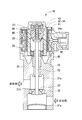
- FIG. FIG. 3 is a cross-sectional view showing a configuration of an EGR valve according to the first embodiment.
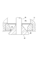
- FIG. 3 is an enlarged cross-sectional view showing a part of the EGR valve according to the first embodiment.
- 9 is a flowchart showing the processing contents of foreign matter trapping diagnosis control according to the first embodiment.
- FIG. 9 is a fully closed reference intake pressure map referred to in order to obtain a fully closed reference intake pressure during deceleration according to the engine speed and the engine load according to the first embodiment.
- FIG. The flowchart which shows the processing content of a foreign material trapping diagnosis control concerning 2nd Embodiment.
- FIG. 10 is a fully closed reference intake pressure map referred to in order to obtain a fully closed reference intake pressure during deceleration according to the engine speed and the engine load according to the second embodiment.
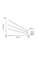
- FIG. FIG. 10 is a map of an intake pressure increase margin that is referred to in order to obtain an intake pressure increase margin according to a foreign matter diameter bitten into an EGR valve and an engine speed according to the second embodiment.
- FIG. 10 is a map of an intake pressure increase margin that is referred to in order to obtain an intake pressure increase margin according to a foreign matter diameter bitten into an EGR valve and an engine speed according to the second embodiment.
- FIG. 1 is a schematic configuration diagram of a gasoline engine system (hereinafter, simply referred to as “engine system”) including an EGR device for an engine in this embodiment.
- This engine system includes a reciprocating type gasoline engine (hereinafter, simply referred to as “engine”) 1.
- An intake passage 3 is connected to the intake port 2 of the engine 1, and an exhaust passage 5 is connected to the exhaust port 4.
- An air cleaner 6 is provided at the inlet of the intake passage 3.
- the intake passage 3 includes a surge tank 3a, and the intake passage 3 upstream of the surge tank 3a is provided with an electronic throttle device 14 for adjusting the amount of intake air in the intake passage 3.
- the electronic throttle device 14 includes a throttle valve 21, a DC motor 22 for driving the throttle valve 21 to open and close, and a throttle sensor 23 for detecting an opening (throttle opening) TA of the throttle valve 21.
- the opening degree of the throttle valve 21 is adjusted by driving the DC motor 22 according to the operation of the accelerator pedal 26 by the driver.
- the throttle sensor 23 corresponds to an example of load detection means for detecting the throttle opening TA corresponding to the load of the engine 1.
- the exhaust passage 5 is provided with a catalytic converter 15 for purifying exhaust gas.
- the engine 1 is provided with an injector 25 for injecting and supplying fuel (gasoline) to the combustion chamber 16. Fuel is supplied to the injector 25 from a fuel tank (not shown). Further, the engine 1 is provided with an ignition device 29 for igniting a mixture of fuel and intake air formed in the combustion chamber 16.
- the EGR device 10 is a device for recirculating a part of exhaust gas discharged from the combustion chamber 16 of the engine 1 to the exhaust passage 5 to the combustion chamber 16 as EGR gas, and transfers the EGR gas from the exhaust passage 5 to the intake passage 3.
- An EGR passage 17 for flowing the gas and an EGR valve 18 provided in the passage 17 for adjusting the flow rate of the EGR gas in the EGR passage 17 are provided.
- the EGR passage 17 is provided between the exhaust passage 5 and the intake passage 3 (surge tank 3a). That is, the outlet 17a of the EGR passage 17 is connected to the surge tank 3a downstream of the electronic throttle device 14.
- the inlet 17b of the EGR passage 17 is connected to the exhaust passage 5. As a result, the EGR gas flowing through the EGR passage 17 is introduced into the surge tank 3a.
- the EGR passage 17 is provided with an EGR cooler 20 for cooling the EGR gas flowing through the passage 17.
- the EGR valve 18 is arranged in the EGR passage 17 downstream of the EGR cooler 20.
- FIG. 2 is a sectional view showing the structure of the EGR valve 18.
- FIG. 3 shows a part of the EGR valve 18 in an enlarged sectional view.
- the EGR valve 18 is composed of a poppet type electric valve. That is, the EGR valve 18 includes a housing 31, a valve seat 32 provided in the housing 31, a valve body 33 that is seatable and movable with respect to the valve seat 32 in the housing 31, and a valve body 33. And a step motor 34 for making a stroke motion of the.
- the housing 31 has an inlet 31a into which EGR gas is introduced from the exhaust passage 5 side (exhaust side), an outlet 31b from which EGR gas is led out to the intake passage 3 side (intake side), and an inlet 31a.
- a communication passage 31c that communicates with the outlet 31b is included.
- the valve seat 32 is provided in the middle of the communication passage 31c.
- the step motor 34 includes an output shaft 35 configured to be capable of linearly reciprocating motion (stroke motion), and the valve body 33 is fixed to the tip of the output shaft 35.
- the output shaft 35 is movably supported by the housing 31 via a bearing 36 provided in the housing 31.
- a male screw portion 37 is formed on the upper end of the output shaft 35.
- a spring receiver 38 is formed in the middle of the output shaft 35 (near the lower end of the male screw portion 37).
- the lower surface of the spring receiver 38 is a receiving surface for the compression spring 39, and the stopper 40 is formed on the upper surface.
- the valve element 33 has a conical shape, and its conical surface abuts or separates from the valve seat 32.
- the valve body 33 When the valve body 33 contacts the valve seat 32, the valve body 33 is fully closed, and when the valve body 33 separates from the valve seat 32, the valve body 33 opens.
- the valve body 33 is urged by the compression spring 39 provided between the spring receiver 38 and the housing 31 toward the step motor 34, that is, in the valve closing direction in which the valve seat 33 is seated on the valve seat 32. ..
- the valve body 33 in the fully closed state is stroked by the output shaft 35 of the step motor 34 against the biasing force of the compression spring 39, so that the valve body 33 separates from the valve seat 32 (valve opening).
- the valve element 33 moves toward the upstream side (exhaust side) of the EGR passage 17.
- the EGR valve 18 moves from the fully closed state in which the valve body 33 is seated on the valve seat 32 to the upstream side of the EGR passage 17 against the exhaust pressure or the intake pressure of the engine 1, thereby The body 33 separates from the valve seat 32 and opens.
- the valve body 33 moves in the biasing direction of the compression spring 39 by the output shaft 35 of the step motor 34 from the valve open state, the valve body 33 approaches the valve seat 32 and closes the valve.
- the valve element 33 moves toward the downstream side (intake side) of the EGR passage 17.
- the opening degree of the valve element 33 with respect to the valve seat 32 is adjusted by performing a stroke motion of the output shaft 35 of the step motor 34.
- the output shaft 35 of the EGR valve 18 is capable of performing a stroke motion by a predetermined stroke from a fully closed state in which the valve body 33 is seated on the valve seat 32 to a fully open state in which the valve body 33 is maximally separated from the valve seat 32. It is provided.
- the step motor 34 includes a coil 41, a magnet rotor 42, and a conversion mechanism 43.
- the step motor 34 rotates the magnet rotor 42 by a predetermined number of motor steps when the coil 41 is excited by energization, and the conversion mechanism 43 converts the rotational motion of the magnet rotor 42 into the stroke motion of the output shaft 35. It has become.
- the valve element 33 makes a stroke movement with respect to the valve seat 32.
- the magnet rotor 42 includes a resin rotor body 44 and an annular plastic magnet 45. At the center of the rotor body 44, a female screw portion 46 that is screwed into the male screw portion 37 of the output shaft 35 is formed. When the female screw portion 46 of the rotor body 44 and the male screw portion 37 of the output shaft 35 are screwed together, the rotor body 44 rotates, so that the rotational movement thereof is converted into the stroke movement of the output shaft 35.
- the male screw part 37 and the female screw part 46 constitute the above-mentioned conversion mechanism 43.
- An abutting portion 44 a with which the stopper 40 of the spring receiver 38 abuts is formed in the lower portion of the rotor body 44. When the EGR valve 18 is fully closed, the end surface of the stopper 40 comes into surface contact with the end surface of the contact portion 44a, and the initial position of the output shaft 35 is restricted.
- the opening degree of the valve element 33 of the EGR valve 18 is finely adjusted stepwise from fully closed to fully open by changing the number of motor steps of the step motor 34 stepwise. ing.
- an electronic control unit (ECU) 50 for executing fuel injection control, ignition timing control, intake air amount control, EGR control and the like according to the operating state of the engine 1.
- the ECU 50 controls each of the injector 25, the ignition device 29, the DC motor 22 of the electronic throttle device 14 and the step motor 34 of the EGR valve 18 according to the operating state of the engine 1.
- the ECU 50 includes a central processing unit (CPU), various memories that pre-store a predetermined control program and the like, and temporarily store a calculation result of the CPU, an external input circuit and an external unit connected to these units. And an output circuit.
- the ECU 50 corresponds to an example of EGR valve abnormality diagnosing means in the disclosed technique.
- the ECU 50 corresponds to an example of EGR valve control means for controlling the EGR valve 18.
- the injector 25, the ignition device 29, the electronic throttle device 14 (DC motor 22), and the EGR valve 18 (step motor 34) are connected to the external output circuit.
- the throttle sensor 23 and various sensors 27, 51 to 55 for detecting the operating state of the engine 1 are connected to the external input circuit.
- the various sensors 23, 27, 51 to 55 constitute an example of operating state detecting means.
- an accelerator sensor 27 detects an operation amount of the accelerator pedal 26 as an accelerator opening degree ACC and outputs a detection signal thereof.
- the intake pressure sensor 51 detects the pressure of intake air in the intake passage 3 (surge tank 3a), which is downstream of the electronic throttle device 14 (throttle valve 21) and into which EGR gas flows, as the intake pressure PM, and outputs a detection signal thereof. It is like this.
- the intake pressure sensor 51 corresponds to an example of intake pressure detection means for detecting intake pressure.
- the rotation speed sensor 52 detects the rotation angle (crank angle) of the crankshaft 1a of the engine 1, detects the change in the crank angle as the rotation speed (engine rotation speed) NE of the engine 1, and outputs the detection signal. It is supposed to do.
- the rotation speed sensor 52 constitutes an example of rotation speed detection means for detecting the rotation speed of the engine 1.
- the water temperature sensor 53 detects the cooling water temperature THW of the engine 1 and outputs the detection signal.
- the air flow meter 54 detects the intake air amount Ga flowing in the intake passage 3 immediately downstream of the air cleaner 6 and outputs a detection signal thereof.
- the air-fuel ratio sensor 55 detects the air-fuel ratio A/F in the exhaust gas in the exhaust passage 5 immediately upstream of the catalytic converter 15 and outputs a detection signal thereof.
- the throttle sensor 23, the intake pressure sensor 51, the rotation speed sensor 52, or the air flow meter 54 constitutes an example of load detection means for detecting the load of the engine 1.
- the ECU 50 controls the EGR valve 18 in order to control the EGR according to the operating state of the engine 1 in the entire operating region of the engine 1.
- the ECU 50 controls the EGR valve 18 to be fully closed in order to shut off the EGR during deceleration of the engine 1.
- the ECU 50 is configured to execute "foreign matter trapping diagnosis control" in order to diagnose an abnormality due to valve sticking of the EGR valve 18 including foreign matter trapping.
- FIG. 4 is a flowchart showing an example of the processing contents of the “foreign matter entrapment diagnosis control” executed by the ECU 50.
- This flowchart is a process for diagnosing an abnormality due to foreign matter trapping (valve opening stuck) of the EGR valve 18 when the engine 1 is decelerated and the EGR valve 18 is fully closed or closed. Indicates.
- the ECU 50 takes in various signals indicating the operating state of the engine 1 from various sensors 23, 51, 52, 54. That is, the engine speed NE, the engine load KL, the throttle opening TA, the intake air amount Ga, the intake pressure PM, the engine rotation change ⁇ NE and the throttle opening change ⁇ TA, and the step motor 34 corresponding to the control opening of the EGR valve 18.
- the motor step number STegr is taken in respectively.
- the ECU 50 can obtain the engine load KL based on the throttle opening TA, the intake pressure PM, the engine speed NE, or the intake air amount Ga.
- the ECU 50 can obtain the change in the throttle opening TA per unit time as the throttle opening change ⁇ TA.
- the ECU 50 can determine the change in the engine speed NE per unit time as the engine speed change ⁇ NE.
- the motor step number STegr has a relationship proportional to the control opening degree (EGR opening degree) of the EGR valve 18, that is, the opening degree of the valve body 33 with respect to the valve seat 32.
- the ECU 50 determines whether or not the operating state of the engine 1 is within the foreign matter trapping detection range.
- the ECU 50 can determine, for example, whether the range defined by the relationship between the engine speed NE and the engine load KL is within a predetermined range suitable for detecting foreign matter trapping. The deceleration operation or the steady operation of the engine 1 is included in the predetermined range. If the determination result is affirmative, the ECU 50 shifts the process to step 120, and if the determination result is negative, returns the process to step 100.
- the ECU 50 determines whether or not the motor step number STegr is smaller than “8 steps”. “8 steps” is an example, and corresponds to a minute opening degree of the EGR valve 18. Here, when the number of motor steps STegr is “8 steps or less”, it corresponds to the fully closed control of the EGR valve 18. If the determination result is affirmative, the ECU 50 shifts the process to step 130, and if the determination result is negative, returns the process to step 100.
- the ECU 50 takes in the fully closed reference intake pressure PMegr0 during deceleration according to the engine speed NE and the engine load KL.
- the ECU 50 refers to, for example, a preset fully closed reference intake pressure map as shown in FIG. 5, to detect (acquire) the engine speed NE and to detect (acquire) the engine load KL. Accordingly, the fully closed reference intake pressure PMegr0 during deceleration can be calculated.
- this fully closed reference intake pressure map the relationship between the fully closed reference intake pressure PMegr0 with respect to the engine speed NE and the engine load KL when the opening degree of the valve body 33 of the EGR valve 18 is "0", that is, when the valve is fully closed is preset. This is the map.
- the intake pressure PM during deceleration of the engine 1 has a correlation with the engine load KL regardless of whether foreign matter is caught in the EGR valve 18, and the two are substantially proportional.
- the fully closed reference intake pressure PMegr0 is set for the engine speed NE and the engine load KL.
- the ECU 50 takes in the intake pressure rise margin ⁇ according to the engine speed NE.
- the ECU 50 can calculate the intake pressure increase margin ⁇ according to the detected (acquired) engine rotational speed NE by referring to a preset predetermined intake pressure increase margin map.
- This intake air pressure increase amount ⁇ means the amount of increase in the intake pressure PM that occurs when the EGR valve 18 is stuck and opened due to the foreign matter FB being caught during valve closing control of the EGR valve 18. Therefore, the intake pressure increase margin ⁇ increases as the diameter of the foreign matter FB (foreign matter diameter) increases and the opening degree of the EGR valve 18 due to the foreign matter being caught increases.
- the higher the engine speed NE the smaller the EGR amount taken into the engine 1 per revolution, and the smaller the intake pressure increase margin ⁇ becomes.
- the ECU 50 determines whether or not the detected (acquired) intake pressure PM is larger than the addition result (PMegr0+ ⁇ ) of the fully closed reference intake pressure PMegr0 and the intake pressure increase margin ⁇ . Therefore, the ECU 50 obtains the addition result (PMegr0+ ⁇ ) by adding the intake pressure increase margin ⁇ to the fully closed reference intake pressure PMegr0. If the determination result is affirmative, the ECU 50 shifts the processing to step 160, and if the determination result is negative, the ECU 50 shifts the processing to step 170.
- the ECU 50 determines that the EGR valve 18 is abnormal due to foreign matter trapping (abnormality due to foreign matter trapping), and returns the process to step 100.
- the ECU 50 can store the determination result in the memory or execute a predetermined abnormality notification control in response to the determination result.
- step 170 the ECU 50 determines that the EGR valve 18 is normal (normal because no foreign matter is caught), and returns the process to step 100.
- the ECU 50 calculates the fully closed reference intake pressure PMegr0 (reference intake pressure) according to the acquired engine speed NE and the acquired engine load KL, and acquires the acquired engine speed.
- the intake pressure increase amount ⁇ X according to NE is calculated, the calculated intake pressure increase amount ⁇ X is added to the calculated fully closed reference intake pressure PMegr0, and EGR is calculated based on the addition result (PMegr0+ ⁇ X) and the acquired intake pressure PM.
- the presence/absence of an abnormality due to the foreign matter being caught in the valve 18 (sticking the valve open) is determined.
- the fully closed reference intake pressure PMegr0 reference intake air that is calculated according to the acquired engine speed NE and the acquired engine load KL.
- the intake pressure rise amount ⁇ calculated according to the acquired engine speed NE is added to the pressure), and foreign matter is caught (opened) in the EGR valve 18 based on the addition result (PMegr0+ ⁇ ) and the acquired intake pressure PM. Whether there is an abnormality due to valve sticking) is determined.
- the fully closed reference intake pressure PMegr0 corresponding to various operating states of the engine 1 is calculated, and therefore the operating state of the engine 1 is determined by sonic or the like when determining whether or not there is an abnormality due to foreign matter trapping in the EGR valve 18. It is not necessary to limit the operating conditions of the EGR valve 18 to specific conditions. Further, since the intake pressure increase margin ⁇ calculated according to the engine speed NE is added to the fully closed reference intake pressure PMegr0 to determine whether or not there is an abnormality due to foreign matter entrapment, the EGR valve 18 is entrapped by foreign matter.
- FIG. 6 is a flowchart showing an example of the processing contents of the “foreign matter entrapment diagnosis control” executed by the ECU 50. This flowchart is a process for diagnosing an abnormality due to foreign matter trapping (valve opening stuck) of the EGR valve 18 when the engine 1 is decelerated and the EGR valve 18 is fully closed or closed. Indicates.
- the ECU 50 takes in the engine speed NE, the engine load KL, the throttle opening TA, the intake amount Ga, the intake pressure PM, and the motor step number STegr, respectively.
- the ECU 50 determines whether or not the operating state of the engine 1 is within the foreign matter trapping detection range.
- the ECU 50 can determine, for example, whether the range defined by the relationship between the engine speed NE and the engine load KL is within a predetermined range suitable for detecting foreign matter trapping. The deceleration operation or the steady operation of the engine 1 is included in the predetermined range. If the determination result is affirmative, the ECU 50 shifts the processing to step 220, and if the determination result is negative, returns the processing to step 200.
- the ECU 50 determines whether the motor step number STegr is smaller than "8 steps". “8 steps” is an example, and corresponds to a minute opening degree of the EGR valve 18. The ECU 50 shifts the processing to step 230 when the determination result is affirmative, and returns the processing to step 200 when the determination result is negative.
- the ECU 50 takes in the fully closed reference intake pressure PMegr0 during deceleration according to the engine speed NE and the engine load KL.
- the ECU 50 refers to, for example, a preset fully closed reference intake pressure map as shown in FIG. 7, to detect (acquire) the engine speed NE and to detect (acquire) the engine load KL. Accordingly, the fully closed reference intake pressure PMegr0 during deceleration can be calculated.
- the description of the fully closed reference intake pressure map is based on that of the fully closed reference intake pressure map of FIG. 5 in the first embodiment.
- the fully closed reference intake pressure according to the engine speed NE and the engine load KL is taken into consideration in FIG. PMegr0 is set.
- the ECU 50 refers to, for example, a preset intake pressure increase margin map as shown in FIG. 8, to determine the intake pressure increase margin ⁇ X corresponding to the foreign object diameter ⁇ X and detected (acquired) by the engine speed NE. It can be calculated.
- the intake pressure increase amount ⁇ X is the amount of increase in the intake pressure PM that occurs when the EGR valve 18 is stuck and does not close when the EGR valve 18 is closed and controlled by the foreign matter FB being bitten. means. Therefore, as shown in FIG. 8, the intake pressure increase margin ⁇ X increases as the foreign substance diameter ⁇ X increases, because the opening degree due to the sticking of the EGR valve 18 increases. The higher the engine speed NE, the smaller the amount of EGR gas taken into the engine 1 per revolution, and therefore the intake pressure increase margin ⁇ X becomes smaller. In FIG.
- a thick one-dot chain line indicates a foreign matter diameter ⁇ X of “0.9 (mm)”
- a thick broken line indicates a foreign matter diameter ⁇ X of “0.6 (mm)”
- a thick two-dot chain line indicates a foreign matter diameter ⁇ X.
- the ECU 50 obtains the plurality of foreign object diameters ⁇ X ( ⁇ 0, ⁇ 0.3, ⁇ 0.6, ⁇ 0.9) which are assumed to be the foreign object bite (fixed valve open) of the EGR valve 18.
- a plurality of intake pressure rise margins ⁇ X ( ⁇ 0, ⁇ 0.3, ⁇ 0.6, ⁇ 0.9) corresponding to the rotational speed NE are calculated.
- the foreign substance diameter ⁇ X corresponds to the opening degree of the EGR valve 18 opened by the foreign substance being caught.
- the ECU 50 determines whether or not the intake pressure PM taken in is larger than the addition result (PMegr0+ ⁇ 0.3) of the fully closed reference intake pressure PMegr0 and the intake pressure increase margin ⁇ 0.3. Therefore, the ECU 50 obtains the addition result (PMegr0+ ⁇ 0.3) by adding the intake pressure increase margin ⁇ 0.3 to the fully closed reference intake pressure PMegr0.
- the determination result is affirmative, the ECU 50 determines that the foreign matter diameter ⁇ X is “0.3 (mm) or more” and shifts the processing to step 260.
- the determination result is negative, the ECU 50 determines the foreign matter diameter. Assuming that ⁇ X is “0 to 0.3 (mm)”, the process proceeds to step 310.
- the ECU 50 determines whether or not the intake pressure PM taken in is larger than the addition result (PMegr0+ ⁇ 0.6) of the fully closed reference intake pressure PMegr0 and the intake pressure increase margin ⁇ 0.6. Therefore, the ECU 50 obtains the addition result (PMegr0+ ⁇ 0.6) by adding the intake pressure increase margin ⁇ 0.6 to the fully closed reference intake pressure PMegr0.
- the determination result is affirmative, the ECU 50 determines that the foreign matter diameter ⁇ X is “0.6 (mm) or more” and shifts the processing to step 270.
- the determination result is negative, the ECU 50 determines the foreign matter diameter. Assuming that ⁇ X is "0.3 to 0.6 (mm)", the process proceeds to step 360.
- the ECU 50 determines whether or not the intake pressure PM taken in is larger than the addition result (PMegr0+ ⁇ 0.9) of the fully closed reference intake pressure PMegr0 and the intake pressure increase margin ⁇ 0.9. Therefore, the ECU 50 obtains the addition result (PMegr0+ ⁇ 0.9) by adding the intake pressure increase margin ⁇ 0.9 to the fully closed reference intake pressure PMegr0.
- the determination result is affirmative, the ECU 50 determines that the foreign matter diameter ⁇ X is “0.9 (mm) or more” and shifts the processing to step 280.
- the determination result is negative, the ECU 50 determines the foreign matter diameter The processing shifts to step 370 assuming that ⁇ X becomes “0.6 to 0.9 (mm)”.
- the ECU 50 determines that the foreign substance diameter ⁇ X is “0.9 (mm) or more”. That is, the ECU 50 calculates the foreign substance diameter ⁇ X by the process before step 280, and obtains the calculation result of “0.9 (mm) or more”.
- step 290 the ECU 50 determines that the EGR valve 18 is causing an abnormality due to foreign matter being caught.
- the ECU 50 can store the determination result in a memory and execute a predetermined notification control for the driver.
- step 300 the ECU 50 executes idle-up control according to the determined foreign substance diameter ⁇ X.
- the ECU 50 executes the idle-up control according to the foreign matter diameter ⁇ X of 0.9 (mm) or more. That is, if foreign matter is caught in the EGR valve 18 during deceleration of the engine 1, unnecessary EGR gas may leak and flow into the engine 1, which may cause misfire, drivability deterioration, or engine stall. These stalls are more likely to occur as the foreign substance diameter ⁇ X increases, that is, as the EGR gas flow rate leaking into the engine 1 increases. Therefore, in this embodiment, the ECU 50 executes idle-up control according to the foreign substance diameter ⁇ X in order to avoid these engine stalls and the like. Then, the ECU 50 returns the process to step 200.
- step 310 after shifting from step 250, the ECU 5 determines the intake pressure PM taken in as the fully closed reference intake pressure PMegr0 from the addition result (PMegr0+ ⁇ 0) of the fully closed reference intake pressure PMegr0 and the intake pressure increase margin ⁇ 0.
- the foreign matter diameter ⁇ X is obtained by performing an interpolation calculation between the addition result (PMegr0+ ⁇ 0.3) with the intake pressure increase margin ⁇ 0.3. That is, the ECU 50 calculates a plurality of addition results (PMegr0+ ⁇ X) of the acquired intake pressure PM for the opening degree between the plurality of assumed foreign substance diameters ⁇ X ( ⁇ 0, ⁇ 0.3, ⁇ 0.6, ⁇ 0.9).
- the ECU 50 can employ, for example, the following calculation formula 1 (F1) for the interpolation calculation.
- ⁇ X [1-(PMegr0+ ⁇ 0.3-PM)/(PMegr0+ ⁇ 0.3-PMegr0)]*( ⁇ 0.3- ⁇ 0)+ ⁇ 0 (F1)
- step 320 the ECU 50 determines that the foreign substance diameter ⁇ X is the value obtained in the immediately preceding step.
- the ECU 50 determines that the foreign substance diameter ⁇ X is a value in the range of “0 to 0.3 (mm)”. That is, the ECU 50 calculates the foreign substance diameter ⁇ X by the interpolation calculation before step 320, and obtains a certain determination result.
- step 330 the ECU 50 determines whether or not the determined foreign substance diameter ⁇ X is “0” or less. If the determination result is affirmative, the ECU 50 determines that there is no foreign matter trapped, and shifts the processing to step 340. If the determination result is negative, the ECU 50 determines that there is foreign matter trapped and the processing proceeds to step 290. Then, the process proceeds to step 290 and thereafter.
- the ECU 50 determines that the EGR valve 18 is normal, assuming that the EGR valve 18 does not cause an abnormality due to foreign matter trapping.
- the ECU 50 can store this determination result in the memory.
- step 350 the ECU 50 executes idle control when the EGR valve 18 is normal. That is, unless foreign matter is caught in the EGR valve 18 during deceleration of the engine 1, there is no risk of engine stalling due to EGR gas inflow into the engine 1, so the ECU 50 executes normal idle control. Then, the ECU 50 returns the process to step 200.
- step 360 the ECU 5 determines the intake pressure PM taken in based on the addition result (PMegr0+ ⁇ 0.3) of the fully closed reference intake pressure PMegr0 and the intake pressure rise margin ⁇ 0.3.
- the foreign matter diameter ⁇ X is obtained by performing an interpolation calculation between the addition result (PMegr0+ ⁇ 0.6) of the intake pressure PMegr0 and the intake pressure increase margin ⁇ 0.6.
- the ECU 50 obtains the acquired intake pressure PM by performing an interpolation calculation between two adjacent addition results (PMegr0+ ⁇ 0.3, PMegr0+ ⁇ 0.6) whose values are close to each other.
- the ECU 50 can employ, for example, the following calculation formula 2 (F2) for the interpolation calculation.
- ⁇ X [1-(PMegr0+ ⁇ 0.6-PM)/(PMegr0+ ⁇ 0.6-PMegr0- ⁇ 0.3)]*( ⁇ 0.6- ⁇ 0.3)+ ⁇ 0.3 (F2)
- the ECU 50 shifts the processing to step 320 and executes the processing of step 320 and thereafter.
- step 370 after shifting from step 270, the ECU 5 determines the intake pressure PM taken in from the addition result (PMegr0+ ⁇ 0.6) of the fully closed reference intake pressure PMegr0 and the intake pressure increase margin ⁇ 0.6.
- the foreign matter diameter ⁇ X is obtained by performing an interpolation calculation between the addition result (PMegr0+ ⁇ 0.9) of the intake pressure PMegr0 and the intake pressure increase margin ⁇ 0.9.
- the ECU 50 obtains the acquired intake pressure PM by performing an interpolation calculation between two adjacent addition results (PMegr0+ ⁇ 0.6, PMegr0+ ⁇ 0.9) that are close in value.
- the ECU 50 can employ the following calculation formula 3 (F3) for the interpolation calculation, for example.
- ⁇ X [1-(PMegr0+ ⁇ 0.9-PM)/(PMegr0+ ⁇ 0.9-PMegr0- ⁇ 0.6)]*( ⁇ 0.9- ⁇ 0.6)+ ⁇ 0.6 (F3)
- the ECU 50 shifts the processing to step 320 and executes the processing of step 320 and thereafter.
- the ECU 50 calculates the fully closed reference intake pressure PMegr0 (reference intake pressure) according to the acquired engine speed NE and the acquired engine load KL, and acquires the acquired engine speed.
- the intake pressure increase amount ⁇ X according to NE is calculated, the calculated intake pressure increase amount ⁇ X is added to the calculated fully closed reference intake pressure PMegr0, and EGR is calculated based on the addition result (PMegr0+ ⁇ X) and the acquired intake pressure PM.
- the presence/absence of an abnormality due to the foreign matter being caught in the valve 18 (sticking the valve open) is determined.
- the ECU 50 calculates the foreign matter diameter ⁇ X (opening degree) of the EGR valve 18 based on the addition result (PMegr0+ ⁇ X) and the acquired intake pressure PM, and the calculated EGR valve 18
- a predetermined value for example, “0.9” (or can be set to “become larger than approximately 0”)
- the EGR valve 18 catches the foreign matter ( It is also possible to determine that an abnormality due to valve opening (stuck) has occurred, and the calculated foreign matter diameter ⁇ X of the EGR valve 18 becomes approximately 0 (or "when it becomes less than or equal to a predetermined value"). In this case, it is determined that the EGR valve 18 does not cause an abnormality due to foreign matter being caught.
- the ECU 50 causes the EGR valve 18 to have a plurality of different intake pressure increase margins ⁇ X corresponding to a plurality of foreign body diameters ⁇ X (opening degrees) in which foreign matter trapping (valve openness) is assumed.
- a plurality of different addition results (PMegr0+ ⁇ X) of the calculated plurality of intake pressure rise margins ⁇ X and the calculated fully closed reference intake pressure PMegr0 are compared with the acquired intake pressure PM, and the acquired intake pressure PM is
- the EGR valve 18 determines the foreign substance diameter ⁇ X (opening) according to the intake pressure increase margin ⁇ X that constitutes the addition result (PMegr0+ ⁇ X) according to the determination. Is calculated as the foreign substance diameter ⁇ X (opening).
- the ECU 50 calculates a plurality of addition results (the calculated intake air pressure PM) for the foreign matter diameter ⁇ X (opening) between the plurality of foreign matter diameters ⁇ X (opening). It is designed to be obtained by performing an interpolation calculation between two adjacent addition results (PMegr0+ ⁇ X) of which the values are close to each other (PMegr0+ ⁇ X).
- the fully closed reference intake pressure PMegr0 reference intake air that is calculated according to the acquired engine speed NE and the acquired engine load KL.
- the intake pressure rise amount ⁇ X calculated according to the acquired engine speed NE is added to the pressure), and foreign matter is caught (opened) in the EGR valve 18 based on the addition result (PMegr0+ ⁇ X) and the acquired intake pressure PM. Whether there is an abnormality due to valve sticking) is determined.
- the fully closed reference intake pressure PMegr0 corresponding to various operating states of the engine 1 is calculated, and therefore the operating state of the engine 1 is determined by sonic or the like when determining whether or not there is an abnormality due to foreign matter trapping in the EGR valve 18. It is not necessary to limit the operating conditions of the EGR valve 18 to specific conditions. Further, since the intake pressure rise margin ⁇ X calculated according to the engine speed NE is added to the fully closed reference intake pressure PMegr0 to determine whether or not there is an abnormality due to foreign matter trapping, the EGR valve 18 is trapped by foreign matter. The increase amount of the intake pressure PM caused by the fact that the valve does not close due to the above is reflected in the determination of whether or not there is an abnormality due to the foreign matter being caught.
- the foreign matter diameter ⁇ X of the foreign matter FB caught in the EGR valve 18 is based on the addition result of the fully closed reference intake pressure PMegr0 and the intake pressure increase margin ⁇ X and the acquired intake pressure PM.
- the obtained foreign substance diameter ⁇ X (opening) can be used for control for coping with an abnormality due to foreign substance jamming (valve opening stuck). In this embodiment, it can be used to execute the idle-up control according to the foreign substance diameter ⁇ X.
- the intake pressure increase margin ⁇ X changes.
- the foreign matter diameter ⁇ X corresponding to each intake pressure increase margin ⁇ X is obtained as the foreign matter diameter ⁇ X due to the foreign matter being caught in the EGR valve 18. Therefore, the foreign substance diameter ⁇ X is required with a small variation. Therefore, the foreign substance diameter ⁇ X (opening) related to the foreign substance biting (valve opening fixation) of the EGR valve 18 can be obtained with high accuracy.
- the two adjacent adjacent ones of the plurality of addition results (PMegr0+ ⁇ X) are close in value. Since the addition result (PMegr0+ ⁇ X) is obtained by interpolation calculation, it is not necessary to retain a map or a function formula data for calculating the intake pressure rise margin ⁇ X for the intermediate foreign substance diameter. Therefore, it is not necessary to store in the memory of the ECU 50 data such as an intake pressure rise margin map according to all foreign object diameters ⁇ X (opening degrees), and the burden on the ECU 50 can be reduced.
- the fully closed reference intake pressure PMegr0 according to the acquired engine speed NE and the acquired engine load KL is calculated by referring to a predetermined fully closed reference intake pressure map.
- the intake pressure increase margins ⁇ and ⁇ X corresponding to the acquired engine speed NE are obtained by referring to the predetermined intake pressure increase margin map. It is also possible to obtain the intake pressure rise margin according to the acquired engine speed by referring to the rise margin function formula.
- the EGR device of the engine is embodied as a so-called “high-pressure loop type” EGR device in a gasoline engine system that does not include a supercharger.
- a gasoline engine system that includes a supercharger The so-called “high-pressure loop type” or “low-pressure loop type” EGR device can also be embodied.
- the EGR device of the engine is applied to the gasoline engine system, but this EGR device can also be applied to the diesel engine system.
- the idle-up control for avoiding engine stall or the like can be omitted even if it is determined that the EGR valve is abnormal due to foreign matter being caught (abnormality due to stuck valve opening).
- the intake pressure PM detected by the intake pressure sensor 51 is acquired, but the intake pressure is acquired by estimating the intake pressure from the throttle opening detected by the throttle sensor. It can also be configured to do so.
- the abnormality due to the foreign matter being caught in the EGR valve 18 is assumed as the abnormality due to the stuck open valve of the EGR valve 18, but the abnormality is not limited to the abnormality due to the foreign matter being caught, and the valve is opened for other reasons. It is also possible to assume an abnormality in which the valve is not fully closed.
- the ECU 50 determines that the EGR valve 18 does not cause an abnormality due to foreign matter trapping when the calculated opening degree of the EGR valve 18 is “nearly 0”. , Instead of the condition of “substantially 0”, the condition of “below a predetermined value” can be applied.
- the foreign matter bite is diagnosed based on the foreign matter diameter ⁇ X that is bitten into the EGR valve 18, but not limited to the foreign matter diameter ⁇ X, the valve body and the valve seat that are generated when the foreign matter is bitten. It is also possible to diagnose foreign matter trapping based on the opening area between the and.
- step 290 in FIG. 6 when it is determined in step 290 in FIG. 6 that an abnormality is caused by foreign matter trapping, the determination result is stored in the memory or predetermined notification control is executed, and in step 340.
- the determination result is stored in the memory when it is determined that the abnormality is not caused due to the foreign matter biting, the storage and notification control in these memories may be omitted.
- the processing of steps 290 and 340 in FIG. 6 can be omitted.
- the EGR valve is closed due to the valve opening stuck.
- the amount of increase in the intake pressure that occurs when the valve does not reach the above value is reflected in the determination of whether there is an abnormality due to valve opening sticking. Also in this case, the same effect as that of the second embodiment can be obtained.
- the intake pressure PM taken in is interpolated from the addition result (PMegr0+ ⁇ X) of the fully closed reference intake pressure PMegr0 and the intake pressure increase margin ⁇ X.
- the foreign particle diameter ⁇ X was obtained by calculation.
- the above-described interpolation calculation can be omitted. In this case, it is possible to improve the calculation accuracy of the foreign matter diameter.
- the opening degree of the EGR valve 18 is calculated based on the acquired operating state of the engine 1, and the EGR valve is calculated based on the calculated opening degree.
- another abnormality for example, an abnormality due to stuck valve closing
- This disclosed technology can be applied to the engine EGR device provided in a gasoline engine or a diesel engine.
Landscapes
- Engineering & Computer Science (AREA)
- Chemical & Material Sciences (AREA)
- Combustion & Propulsion (AREA)
- Mechanical Engineering (AREA)
- General Engineering & Computer Science (AREA)
- Exhaust-Gas Circulating Devices (AREA)
Abstract
EGR装置(10)は、エンジン(1)の排気の一部を吸気通路(3)へ流すEGR通路(17)と、同通路(17)のEGR流量を調節するEGR弁(18)と、吸気通路(3)に設けられるスロットル弁(21)と、EGR弁(18)を閉弁制御するときにエンジンの運転状態に基づき全閉基準吸気圧力を演算し、演算した全閉基準吸気圧力に基づきEGR弁(18)の開弁固着による異常を診断する電子制御装置(ECU)(50)とを備える。ECU(50)は、エンジンの回転数及び負荷に応じて演算した全閉基準吸気圧力と回転数に応じて演算した吸気圧力上昇代との加算結果と、吸気圧力とに基づきEGR弁(18)の異物噛み異常を判定する。
Description
この明細書に開示される技術は、エンジンの排気の一部をEGRガスとしてEGR通路を介して吸気通路へ流してエンジンへ還流させるEGR装置に係り、詳しくは、EGR通路に設けられるEGR弁の開弁固着による異常を診断するように構成したエンジンのEGR装置に関する。
従来、この種の技術として、例えば、下記の特許文献1に記載される技術が知られている。この技術は、エンジンの排気還流装置(Exhaust Gas Recirculation(EGR)装置)のための故障検出装置に関する。エンジンは、吸気通路、排気通路、燃料供給手段及び吸気通路に設けられる吸気量調節手段を含む。EGR装置は、EGR通路と電動式のEGR弁とを含む。EGR弁は、弁座、弁体及びモータ等を含む。吸気量調節手段より下流の吸気通路には、吸気圧力を検出するための吸気圧検出手段が設けられる。また、エンジンには、エンジン負荷を検出する負荷検出手段が設けられる。故障検出装置は、エンジンの運転が定常状態であって、所定の判定条件が成立するときに、EGR弁の動作状態に応じて検出される吸気圧力に基づきEGR装置の故障(異常)を判定する故障判定手段を備える。故障判定手段は、エンジンの運転が定常状態であって、所定の判定条件が成立したときに、EGR弁の動作状態に応じて検出される吸気圧力を、所定の判定条件に応じて求められる判定吸気圧力と比較することで、EGR弁の異常(弁座と弁体との間の異物噛み込み等)を判定するようになっている。ここで、所定の判定条件としては、検出されるエンジン負荷が所定の負荷範囲にあり、EGR弁を構成するモータが所定の動作範囲にあることが設定される。
ところが、特許文献1に記載される故障検出装置では、エンジンの運転が定常状態であって所定の判定条件が成立するときを前提に、EGR装置の異常を判定していたので、異常判定の機会が特定の場合に制限されていた。また、この故障検出装置では、所定の負荷範囲がエンジンの低回転軽負荷であること、並びに、所定の動作範囲がEGR弁の小開度であることが、故障判定の前提条件となっていた。そのため、故障判定が、各種バラツキ及び外乱(例えば、タペットクリアランス及びバルブタイミングのずれ、空気密度(温度)、PCV流量、電気負荷など。)の影響を受けるおそれがあり、それらバラツキや外乱を回避しようとすると、EGR弁の小開度の異常(小径異物の噛み込み異常等)については診断できなくなるおそれがあった。また、この故障検出装置では、所定の判定条件に応じて求められる判定吸気圧力が、エンジンの回転数の変動による影響を受けるおそれがあり、異常を精度よく検出することができなかった。
この開示技術は、上記事情に鑑みてなされたものであって、その目的は、エンジンの運転状態やEGR弁の動作状態に関する条件を特定の条件に制限することなくEGR弁の開弁固着による異常を早期に精度よく診断することを可能としたエンジンのEGR装置を提供することにある。
(1)上記目的を達成するために、本発明の態様は、エンジンから排気通路へ排出される排気の一部をEGRガスとしてエンジンへ還流するためにEGRガスを排気通路から吸気通路へ流すEGR通路と、EGR通路におけるEGRガスの流量を調節するためのEGR弁と、吸気通路における吸気量を調節するためのスロットル弁と、EGR弁を閉弁制御しているときに、取得したエンジンの運転状態に基づいて基準吸気圧力を演算し、演算した基準吸気圧力に基づいて少なくともEGR弁の開弁固着による異常を診断するためのEGR弁異常診断手段とを備えたエンジンのEGR装置において、エンジンの運転状態は、スロットル弁より下流の吸気通路における吸気圧力と、エンジンの回転数と、エンジンの負荷とを含み、EGR弁異常診断手段は、基準吸気圧力を、取得した回転数及び取得した負荷に応じて演算し、取得した回転数に応じた吸気圧力上昇代を演算し、演算した基準吸気圧力に演算した吸気圧力上昇代を加算し、その加算結果と取得した吸気圧力とに基づいてEGR弁の開弁固着による異常の有無を判定することを趣旨とする。
上記(1)の構成によれば、エンジンの運転時に、取得した回転数及び取得した負荷に応じて演算される基準吸気圧力に、取得した回転数に応じて演算される吸気圧力上昇代が加算され、その加算結果と取得した吸気圧力とに基づいてEGR弁の開弁固着による異常の有無が判定される。従って、エンジンの各種運転状態に応じた基準吸気圧力が演算されるので、EGR弁の開弁固着による異常の有無を判定するにあたり、エンジンの運転状態をソニック等の特定の条件に制限する必要がなく、EGR弁の動作状態を特定の条件に制限する必要もない。また、開弁固着による異常の有無の判定のために、エンジンの回転数に応じて演算される吸気圧力上昇代が基準吸気圧力に加算されるので、EGR弁が開弁固着により閉弁に至らないことで生じる吸気圧力の上昇量が、開弁固着による異常の有無の判定に反映される。
(2)上記目的を達成するために、上記(1)の構成において、EGR弁異常診断手段は、加算結果と取得した吸気圧力とに基づいてEGR弁の開度を演算し、演算したEGR弁の開度が所定値以上又は略0より大きくなった場合には、EGR弁が開弁固着による異常を生じさせていると判定し、演算したEGR弁の開度が所定値以下又は略0となった場合には、EGR弁が開弁固着による異常を生じさせていないと判定することが好ましい。ここで、「略0」は、0及び0に極めて近似する値を含む。
上記(2)の構成によれば、上記(1)の構成の作用に加え、基準吸気圧力と吸気圧力上昇代との加算結果と取得した吸気圧力とに基づいてEGR弁の開度を演算することで、EGR弁の開弁固着による異常の有無が判定される。従って、開弁固着による異常の有無の判定を通じて開弁固着によるEGR弁の開度を求めることが可能となる。
(3)上記目的を達成するために、上記(2)の構成において、EGR弁異常診断手段は、EGR弁の開弁固着が想定される複数の開度に応じた異なる複数の吸気圧力上昇代を演算し、演算した複数の吸気圧力上昇代それぞれと演算した基準吸気圧力との異なる複数の加算結果と取得した吸気圧力とを比較し、取得した吸気圧力が演算した複数の加算結果と等しい又は近似すると判定した場合に、その判定に係る加算結果を構成する吸気圧力上昇代に応じた開度を前記EGR弁の開度として求めることが好ましい。
上記(3)の構成によれば、上記(2)の構成の作用に加え、EGR弁の開弁固着による開度が変われば吸気圧力上昇代が変わるところ、開弁固着が想定される複数の吸気圧力上昇代それぞれに応じた開度がEGR弁の開度として求められる。従って、少ないばらつきで開度が求められる。
(4)上記目的を達成するために、上記(3)の構成において、EGR弁異常診断手段は、想定した複数の開度の間の開度については、取得した吸気圧力を、演算した複数の加算結果のうち値が近い隣り合う二つの加算結果の間で補間計算することにより求めることが好ましい。
上記(4)の構成によれば、上記(3)の構成の作用に加え、想定した複数の開度の間の開度(中間開度)については、複数の加算結果のうち値が近い隣り合う二つの加算結果の間で補間計算により求められるので、中間開度について、吸気圧力上昇代を演算するためのデータを予め保有する必要がない。
(5)上記目的を達成するために、本発明の別の態様は、エンジンから排気通路へ排出される排気の一部をEGRガスとしてエンジンへ還流するためにEGRガスを排気通路から吸気通路へ流すEGR通路と、EGR通路におけるEGRガスの流量を調節するためのEGR弁と、吸気通路における吸気量を調節するためのスロットル弁と、EGR弁を閉弁制御しているときに、取得したエンジンの運転状態に基づいてEGR弁の開度を演算し、演算した開度に基づいて少なくともEGR弁の開弁固着による異常を診断するためのEGR弁異常診断手段とを備えたエンジンのEGR装置において、エンジンの運転状態は、スロットル弁より下流の吸気通路における吸気圧力と、エンジンの回転数と、エンジンの負荷とを含み、EGR弁異常診断手段は、取得した回転数及び取得した負荷に応じた基準吸気圧力を演算し、取得した回転数に応じた吸気圧力上昇代を演算し、演算した基準吸気圧力に演算した吸気圧力上昇代を加算し、その加算結果と取得した吸気圧力とに基づいてEGR弁の開度を演算することを趣旨とする。
上記(5)の構成によれば、エンジンの運転時に、取得した回転数及び取得した負荷に応じて演算される基準吸気圧力に、取得した回転数に応じて演算される吸気圧力上昇代が加算され、その加算結果と取得した吸気圧力とに基づいてEGR弁の開度が演算される。従って、エンジンの各種運転状態に応じた基準吸気圧力が演算されるので、EGR弁の開弁固着による異常の有無を判定するにあたり、エンジンの運転状態をソニック等の特定の条件に制限する必要がなく、EGR弁の動作状態を特定の条件に制限する必要もない。また、異物径が0より大きいときは、異物噛み込み(開弁固着)の発生は自明であるとする思想から、EGR弁の開弁固着による異常の有無の判定を省略することもできる。
上記(1)の構成によれば、エンジンの運転状態やEGR弁の動作状態に関する条件を特定の条件に制限することなくEGR弁の開弁固着による異常を早期に精度よく診断することができる。
上記(2)の構成によれば、上記(1)の構成の効果に加え、求められたEGR弁の開度を、開弁固着による異常への対処制御(例えば、アイドルアップ制御)のために使用することができる。
上記(3)の構成によれば、上記(2)の構成の効果に加え、EGR弁の開弁固着に係る開度を高い精度で求めることができる。
上記(4)の構成によれば、上記(3)の構成の効果に加え、全てのEGR弁の開度に応じた吸気圧力上昇代マップ等のデータをEGR弁異常診断手段(電子制御装置)のメモリに記憶する必要がなく、同診断手段の負担軽減を図ることができる。
上記(5)の構成によれば、エンジンの運転状態やEGR弁の動作状態に関する条件を特定の条件に制限することなくEGR弁の開弁固着による異常を早期に精度よく診断することができる。
<第1実施形態>
以下、エンジンのEGR装置をガソリンエンジンシステムに具体化した第1実施形態につき図面を参照して詳細に説明する。
以下、エンジンのEGR装置をガソリンエンジンシステムに具体化した第1実施形態につき図面を参照して詳細に説明する。
[ガソリンエンジンシステムの概要について]
図1に、この実施形態におけるエンジンのEGR装置を含むガソリンエンジンシステム(以下、単に「エンジンシステム」という。)を概略構成図により示す。このエンジンシステムは、レシプロタイプのガソリンエンジン(以下、単に「エンジン」という。)1を備える。エンジン1の吸気ポート2には、吸気通路3が接続され、排気ポート4には、排気通路5が接続される。吸気通路3の入口には、エアクリーナ6が設けられる。
図1に、この実施形態におけるエンジンのEGR装置を含むガソリンエンジンシステム(以下、単に「エンジンシステム」という。)を概略構成図により示す。このエンジンシステムは、レシプロタイプのガソリンエンジン(以下、単に「エンジン」という。)1を備える。エンジン1の吸気ポート2には、吸気通路3が接続され、排気ポート4には、排気通路5が接続される。吸気通路3の入口には、エアクリーナ6が設けられる。
吸気通路3はサージタンク3aを含み、サージタンク3aより上流の吸気通路3には、吸気通路3における吸気量を調節するための電子スロットル装置14が設けられる。この電子スロットル装置14は、スロットル弁21と、スロットル弁21を開閉駆動するためのDCモータ22と、スロットル弁21の開度(スロットル開度)TAを検出するためのスロットルセンサ23とを備える。電子スロットル装置14は、運転者によるアクセルペダル26の操作に応じてDCモータ22が駆動することで、スロットル弁21の開度が調節されるようになっている。スロットルセンサ23は、エンジン1の負荷に相当するスロットル開度TAを検出するための負荷検出手段の一例に相当する。排気通路5には、排気を浄化するための触媒コンバータ15が設けられる。
エンジン1には、燃焼室16に燃料(ガソリン)を噴射供給するためのインジェクタ25が設けられる。インジェクタ25には、燃料タンク(図示略)から燃料が供給されるようになっている。また、エンジン1には、燃焼室16にて形成された燃料と吸気との混合気を点火するための点火装置29が設けられる。
このエンジンシステムには、高圧ループ式のEGR装置10が設けられる。EGR装置10は、エンジン1の燃焼室16から排気通路5へ排出される排気の一部をEGRガスとして燃焼室16へ還流するための装置であり、EGRガスを排気通路5から吸気通路3へ流すためのEGR通路17と、EGR通路17におけるEGRガスの流量を調節するために同通路17に設けられるEGR弁18とを備える。EGR通路17は、排気通路5と、吸気通路3(サージタンク3a)との間に設けられる。すなわち、EGR通路17の出口17aは、電子スロットル装置14より下流にてサージタンク3aに接続される。EGR通路17の入口17bは、排気通路5に接続される。これにより、EGR通路17を流れるEGRガスは、サージタンク3aに導入されるようになっている。
EGR通路17には、同通路17を流れるEGRガスを冷却するためのEGRクーラ20が設けられる。この実施形態で、EGR弁18は、EGRクーラ20より下流のEGR通路17に配置される。
[EGR弁の構成について]
図2に、EGR弁18の構成を断面図により示す。図3に、EGR弁18の一部を拡大断面図により示す。図2に示すように、EGR弁18は、ポペット式の電動弁により構成される。すなわち、EGR弁18は、ハウジング31と、ハウジング31の中に設けられる弁座32と、ハウジング31の中で弁座32に対して着座可能かつ移動可能に設けられる弁体33と、弁体33をストローク運動させるためのステップモータ34とを備える。ハウジング31は、排気通路5の側(排気側)よりEGRガスが導入される導入口31aと、吸気通路3の側(吸気側)へEGRガスを導出する導出口31bと、導入口31aと導出口31bとを連通する連通路31cとを含む。弁座32は、連通路31cの中間に設けられる。
図2に、EGR弁18の構成を断面図により示す。図3に、EGR弁18の一部を拡大断面図により示す。図2に示すように、EGR弁18は、ポペット式の電動弁により構成される。すなわち、EGR弁18は、ハウジング31と、ハウジング31の中に設けられる弁座32と、ハウジング31の中で弁座32に対して着座可能かつ移動可能に設けられる弁体33と、弁体33をストローク運動させるためのステップモータ34とを備える。ハウジング31は、排気通路5の側(排気側)よりEGRガスが導入される導入口31aと、吸気通路3の側(吸気側)へEGRガスを導出する導出口31bと、導入口31aと導出口31bとを連通する連通路31cとを含む。弁座32は、連通路31cの中間に設けられる。
ステップモータ34は、直進的に往復運動(ストローク運動)可能に構成された出力軸35を備え、その出力軸35の先端に弁体33が固定される。出力軸35はハウジング31に設けられる軸受36を介してハウジング31に対しストローク運動可能に支持される。出力軸35の上端部には、雄ねじ部37が形成される。出力軸35の中間(雄ねじ部37の下端付近)には、スプリング受け38が形成される。スプリング受け38は、下面が圧縮スプリング39の受け面となっており、上面にはストッパ40が形成される。
弁体33は円錐形状をなし、その円錐面が弁座32に対して当接又は離間するようになっている。弁体33が弁座32に当接することにより弁体33が全閉となり、弁体33が弁座32から離間することにより、弁体33が開弁するようになっている。弁体33は、スプリング受け38とハウジング31との間に設けられた圧縮スプリング39によりステップモータ34の側へ、すなわち弁座32に着座する閉弁方向へ、付勢されるようになっている。そして、全閉状態の弁体33が、ステップモータ34の出力軸35により、圧縮スプリング39の付勢力に抗して、ストローク運動することにより、弁体33が弁座32から離間(開弁)する。この開弁時には、弁体33は、EGR通路17の上流側(排気側)へ向けて移動する。このように、このEGR弁18は、弁体33が弁座32に着座した全閉状態から、エンジン1の排気圧力又は吸気圧力に抗してEGR通路17の上流側へ移動することで、弁体33が弁座32から離れて開弁する。一方、開弁状態から、弁体33を、ステップモータ34の出力軸35により圧縮スプリング39の付勢方向へ移動させることで、弁体33が弁座32に近付いて閉弁する。この閉弁時には、弁体33は、EGR通路17の下流側(吸気側)へ向けて移動する。
この実施形態では、ステップモータ34の出力軸35をストローク運動させることにより、弁座32に対する弁体33の開度が調節されるようになっている。EGR弁18の出力軸35は、弁体33が弁座32に着座する全閉状態から、弁体33が弁座32から最大限離間する全開状態までの間で所定のストロークだけストローク運動可能に設けられる。
ステップモータ34は、コイル41、マグネットロータ42及び変換機構43を含む。ステップモータ34は、コイル41が通電により励磁されることで、マグネットロータ42を所定のモータステップ数だけ回転させ、変換機構43によりマグネットロータ42の回転運動を出力軸35のストローク運動に変換するようになっている。この出力軸35のストローク運動に伴って、弁体33が弁座32に対しストローク運動するようになっている。
マグネットロータ42は、樹脂製のロータ本体44と、円環状のプラスチックマグネット45とを含む。ロータ本体44の中心には、出力軸35の雄ねじ部37に螺合する雌ねじ部46が形成される。ロータ本体44の雌ねじ部46と出力軸35の雄ねじ部37とが螺合した状態で、ロータ本体44が回転することで、その回転運動が出力軸35のストローク運動に変換される。ここで、雄ねじ部37と雌ねじ部46により、上記した変換機構43が構成される。ロータ本体44の下部には、スプリング受け38のストッパ40が当接する当接部44aが形成される。EGR弁18の全閉時には、ストッパ40の端面が、当接部44aの端面に面接触し、出力軸35の初期位置が規制されるようになっている。
この実施形態では、ステップモータ34のモータステップ数を段階的に変えることにより、EGR弁18の弁体33の開度を、全閉から全開までの間で段階的に微少に調節するようになっている。
[エンジンシステムの電気的構成について]
この実施形態では、エンジン1の運転状態に応じて燃料噴射制御、点火時期制御、吸気量制御及びEGR制御等をそれぞれ実行するための電子制御装置(ECU)50が設けられる。ECU50は、エンジン1の運転状態に応じて、インジェクタ25、点火装置29、電子スロットル装置14のDCモータ22及びEGR弁18のステップモータ34のそれぞれを制御するようになっている。ECU50は、中央処理装置(CPU)と、所定の制御プログラム等を予め記憶したり、CPUの演算結果等を一時的に記憶したりする各種メモリと、これら各部と接続される外部入力回路及び外部出力回路とを備える。ECU50は、この開示技術におけるEGR弁異常診断手段の一例に相当する。また、ECU50は、EGR弁18を制御するためのEGR弁制御手段の一例に相当する。外部出力回路には、インジェクタ25、点火装置29、電子スロットル装置14(DCモータ22)及びEGR弁18(ステップモータ34)が接続される。外部入力回路には、スロットルセンサ23をはじめエンジン1の運転状態を検出するための各種センサ27,51~55が接続される。各種センサ23,27,51~55は、運転状態検出手段の一例を構成する。
この実施形態では、エンジン1の運転状態に応じて燃料噴射制御、点火時期制御、吸気量制御及びEGR制御等をそれぞれ実行するための電子制御装置(ECU)50が設けられる。ECU50は、エンジン1の運転状態に応じて、インジェクタ25、点火装置29、電子スロットル装置14のDCモータ22及びEGR弁18のステップモータ34のそれぞれを制御するようになっている。ECU50は、中央処理装置(CPU)と、所定の制御プログラム等を予め記憶したり、CPUの演算結果等を一時的に記憶したりする各種メモリと、これら各部と接続される外部入力回路及び外部出力回路とを備える。ECU50は、この開示技術におけるEGR弁異常診断手段の一例に相当する。また、ECU50は、EGR弁18を制御するためのEGR弁制御手段の一例に相当する。外部出力回路には、インジェクタ25、点火装置29、電子スロットル装置14(DCモータ22)及びEGR弁18(ステップモータ34)が接続される。外部入力回路には、スロットルセンサ23をはじめエンジン1の運転状態を検出するための各種センサ27,51~55が接続される。各種センサ23,27,51~55は、運転状態検出手段の一例を構成する。
ここで、各種センサとして、スロットルセンサ23の他に、アクセルセンサ27、吸気圧センサ51、回転数センサ52、水温センサ53、エアフローメータ54及び空燃比センサ55が設けられる。アクセルセンサ27は、アクセルペダル26の操作量をアクセル開度ACCとして検出し、その検出信号を出力するようになっている。吸気圧センサ51は、電子スロットル装置14(スロットル弁21)より下流であってEGRガスが流れ込む吸気通路3(サージタンク3a)における吸気の圧力を吸気圧力PMとして検出し、その検出信号を出力するようになっている。吸気圧センサ51は、吸気圧力を検出するための吸気圧力検出手段の一例に相当する。回転数センサ52は、エンジン1のクランクシャフト1aの回転角(クランク角)を検出するとともに、そのクランク角の変化をエンジン1の回転数(エンジン回転数)NEとして検出し、その検出信号を出力するようになっている。回転数センサ52は、エンジン1の回転数を検出するための回転数検出手段の一例を構成する。水温センサ53は、エンジン1の冷却水温度THWを検出し、その検出信号を出力するようになっている。エアフローメータ54は、エアクリーナ6の直下流にて吸気通路3を流れる吸気量Gaを検出し、その検出信号を出力するようになっている。空燃比センサ55は、触媒コンバータ15の直上流の排気通路5にて、排気中の空燃比A/Fを検出し、その検出信号を出力するようになっている。スロットルセンサ23、吸気圧センサ51、回転数センサ52又はエアフローメータ54は、エンジン1の負荷を検出するための負荷検出手段の一例を構成する。
この実施形態で、ECU50は、エンジン1の全運転領域において、エンジン1の運転状態に応じてEGRを制御するために、EGR弁18を制御するようになっている。一方、ECU50は、エンジン1の減速時には、EGRを遮断するために、EGR弁18を全閉に制御するようになっている。
ここで、EGR弁18では、図3に示すように、弁座32と弁体33との間でデポジット等の異物FBの噛み込みや付着が問題になることがある。そこで、この実施形態のEGR装置では、ECU50は、異物噛み込みを含むEGR弁18の開弁固着による異常を診断するために「異物噛み込み診断制御」を実行するようになっている。
[異物噛み込み診断制御について]
図4に、ECU50が実行する「異物噛み込み診断制御」の処理内容の一例をフローチャートにより示す。このフローチャートは、エンジン1の減速時であってEGR弁18を全閉に制御するとき又は閉弁制御するときに、EGR弁18の異物噛み込み(開弁固着)による異常を診断するための処理を示す。
図4に、ECU50が実行する「異物噛み込み診断制御」の処理内容の一例をフローチャートにより示す。このフローチャートは、エンジン1の減速時であってEGR弁18を全閉に制御するとき又は閉弁制御するときに、EGR弁18の異物噛み込み(開弁固着)による異常を診断するための処理を示す。
処理がこのルーチンへ移行すると、先ず、ステップ100で、ECU50は、エンジン1の運転状態を示す各種信号を各種センサ等23,51,52,54から取り込む。すなわち、エンジン回転数NE、エンジン負荷KL、スロットル開度TA、吸気量Ga、吸気圧力PM、エンジン回転変化ΔNE及びスロットル開度変化ΔTAと、EGR弁18の制御開度に対応するステップモータ34のモータステップ数STegrとをそれぞれ取り込む。ここで、ECU50は、スロットル開度TA、吸気圧力PM、エンジン回転数NE又は吸気量Gaに基づきエンジン負荷KLを求めることができる。ECU50は、スロットル開度TAの単位時間当たりの変化を、スロットル開度変化ΔTAとして求めることができる。ECU50は、エンジン回転数NEの単位時間当たりの変化を、エンジン回転変化ΔNEとして求めることができる。ここで、モータステップ数STegrは、EGR弁18の制御開度(EGR開度)、すなわち弁座32に対する弁体33の開度に比例する関係を有する。
次に、ステップ110で、ECU50は、エンジン1の運転状態が異物噛み込み検出範囲内か否かを判断する。ECU50は、例えば、エンジン回転数NEとエンジン負荷KLとの関係から規定される範囲が、異物噛み込み検出に適した所定の範囲内であるかを判断することができる。この所定の範囲内として、エンジン1の減速運転又は定常運転が含まれる。ECU50は、この判断結果が肯定となる場合は処理をステップ120へ移行し、この判断結果が否定となる場合は処理をステップ100へ戻す。
ステップ120では、ECU50は、モータステップ数STegrが「8ステップ」より小さいか否かを判断する。「8ステップ」は、一例であり、EGR弁18の微小開度に対応する。ここで、モータステップ数STegrが「8ステップ以下」となる場合は、EGR弁18の全閉制御に相当する。ECU50は、この判断結果が肯定となる場合は処理をステップ130へ移行し、この判断結果が否定となる場合は処理をステップ100へ戻す。
ステップ130では、ECU50は、エンジン回転数NEとエンジン負荷KLに応じた減速時の全閉基準吸気圧力PMegr0を取り込む。ECU50は、例えば、図5に示すように予め設定された全閉基準吸気圧力マップを参照することにより、検出される(取得した)エンジン回転数NEと検出される(取得した)エンジン負荷KLに応じた減速時の全閉基準吸気圧力PMegr0を演算することができる。この全閉基準吸気圧力マップは、EGR弁18の弁体33の開度が「0」、すなわち全閉時における、エンジン回転数NE及びエンジン負荷KLに対する全閉基準吸気圧力PMegr0の関係が予め設定されたマップである。一般に、エンジン1の減速時の吸気圧力PMは、EGR弁18における異物の噛み込みの有無にかかわらずエンジン負荷KLと相関を有し、両者はほぼ比例する。ただし、吸気圧力PMは、エンジン回転数NEに応じて変化するので、図5では、エンジン回転数NE及びエンジン負荷KLに対して全閉基準吸気圧力PMegr0が設定されている。
次に、ステップ140で、ECU50は、エンジン回転数NEに応じた吸気圧力上昇代αを取り込む。ECU50は、予め設定された所定の吸気圧力上昇代マップを参照することにより、検出される(取得した)エンジン回転数NEに応じた吸気圧力上昇代αを演算することができる。この吸気圧力上昇代αは、EGR弁18の閉弁制御時に異物FBの噛み込みによりEGR弁18が開弁固着し、閉弁に至らないことで生じる吸気圧力PMの上昇量を意味する。従って、吸気圧力上昇代αは、異物FBの径(異物径)が大きくなるほどEGR弁18の異物噛み込みによる開度が大きくなるので増加することになる。なお、エンジン回転数NEが高くなるほど1回転当たりにエンジン1に取り込まれるEGR量は少なくなるため、吸気圧力上昇代αは小さくなる。
次に、ステップ150で、ECU50は、検出される(取得した)吸気圧力PMが、全閉基準吸気圧力PMegr0と吸気圧力上昇代αとの加算結果(PMegr0+α)より大きいか否かを判断する。そのために、ECU50は、全閉基準吸気圧力PMegr0に吸気圧力上昇代αを加算することで加算結果(PMegr0+α)を得る。ECU50は、この判断結果が肯定となる場合は処理をステップ160へ移行し、この判断結果が否定となる場合は処理をステップ170へ移行する。
ステップ160では、ECU50は、EGR弁18が異物噛み込みによる異常(異物噛み込みを生じさせていることによる異常)と判定し、処理をステップ100へ戻す。ECU50は、この判定結果をメモリに記憶したり、この判定結果を受けて所定の異常報知制御を実行したりすることができる。
一方、ステップ170では、ECU50は、EGR弁18が正常(異物噛み込みを生じさせていないことから正常)であると判定し、処理をステップ100へ戻す。
上記した異物噛み込み診断制御によれば、ECU50は、全閉基準吸気圧力PMegr0(基準吸気圧力)を、取得したエンジン回転数NE及び取得したエンジン負荷KLに応じて演算し、取得したエンジン回転数NEに応じた吸気圧力上昇代αΦXを演算し、演算した全閉基準吸気圧力PMegr0に演算した吸気圧力上昇代αΦXを加算し、その加算結果(PMegr0+αΦX)と取得した吸気圧力PMとに基づいてEGR弁18の異物噛み込み(開弁固着)による異常の有無を判定するようになっている。
[エンジンのEGR装置の作用及び効果について]
以上説明したこの実施形態におけるエンジンのEGR装置の構成によれば、エンジン1の運転時に、取得したエンジン回転数NE及び取得したエンジン負荷KLに応じて演算される全閉基準吸気圧力PMegr0(基準吸気圧力)に、取得したエンジン回転数NEに応じて演算される吸気圧力上昇代αが加算され、その加算結果(PMegr0+α)と取得した吸気圧力PMとに基づいてEGR弁18の異物噛み込み(開弁固着)による異常の有無が判定される。従って、エンジン1の各種運転状態に応じた全閉基準吸気圧力PMegr0が演算されるので、EGR弁18の異物噛み込みによる異常の有無を判定するにあたり、エンジン1の運転状態をソニック等の特定の条件に制限する必要がなく、EGR弁18の動作状態を特定の条件に制限する必要もない。また、異物噛み込みによる異常の有無の判定のために、エンジン回転数NEに応じて演算される吸気圧力上昇代αが全閉基準吸気圧力PMegr0に加算されるので、EGR弁18が異物噛み込みにより閉弁に至らないことで生じる吸気圧力PMの上昇量が、異物噛み込みによる異常の有無の判定に反映される。このため、エンジン1の運転状態やEGR弁18の動作状態に関する条件を特定の条件に制限することなくEGR弁18の異物噛み込み(開弁固着)による異常を早期に精度よく診断することができる。
以上説明したこの実施形態におけるエンジンのEGR装置の構成によれば、エンジン1の運転時に、取得したエンジン回転数NE及び取得したエンジン負荷KLに応じて演算される全閉基準吸気圧力PMegr0(基準吸気圧力)に、取得したエンジン回転数NEに応じて演算される吸気圧力上昇代αが加算され、その加算結果(PMegr0+α)と取得した吸気圧力PMとに基づいてEGR弁18の異物噛み込み(開弁固着)による異常の有無が判定される。従って、エンジン1の各種運転状態に応じた全閉基準吸気圧力PMegr0が演算されるので、EGR弁18の異物噛み込みによる異常の有無を判定するにあたり、エンジン1の運転状態をソニック等の特定の条件に制限する必要がなく、EGR弁18の動作状態を特定の条件に制限する必要もない。また、異物噛み込みによる異常の有無の判定のために、エンジン回転数NEに応じて演算される吸気圧力上昇代αが全閉基準吸気圧力PMegr0に加算されるので、EGR弁18が異物噛み込みにより閉弁に至らないことで生じる吸気圧力PMの上昇量が、異物噛み込みによる異常の有無の判定に反映される。このため、エンジン1の運転状態やEGR弁18の動作状態に関する条件を特定の条件に制限することなくEGR弁18の異物噛み込み(開弁固着)による異常を早期に精度よく診断することができる。
<第2実施形態>
次に、エンジンのEGR装置をガソリンエンジンシステムに具体化した第2実施形態につき図面を参照して詳細に説明する。
次に、エンジンのEGR装置をガソリンエンジンシステムに具体化した第2実施形態につき図面を参照して詳細に説明する。
なお、以下の説明において、第1実施形態と同等の構成要素については同一の符号を付して説明を省略し、異なった点を中心に説明する。この実施形態では、「異物噛み込み診断制御」の内容の点で、第1実施形態と構成が異なる。
[異物噛み込み診断制御について]
図6に、ECU50が実行する「異物噛み込み診断制御」の処理内容の一例をフローチャートにより示す。このフローチャートは、エンジン1の減速時であってEGR弁18を全閉に制御するとき又は閉弁制御するときに、EGR弁18の異物噛み込み(開弁固着)による異常を診断するための処理を示す。
図6に、ECU50が実行する「異物噛み込み診断制御」の処理内容の一例をフローチャートにより示す。このフローチャートは、エンジン1の減速時であってEGR弁18を全閉に制御するとき又は閉弁制御するときに、EGR弁18の異物噛み込み(開弁固着)による異常を診断するための処理を示す。
処理がこのルーチンへ移行すると、先ず、ステップ200で、ECU50は、エンジン回転数NE、エンジン負荷KL、スロットル開度TA、吸気量Ga、吸気圧力PM及びモータステップ数STegrをそれぞれ取り込む。
次に、ステップ210で、ECU50は、エンジン1の運転状態が異物噛み込み検出範囲内か否かを判断する。ECU50は、例えば、エンジン回転数NEとエンジン負荷KLとの関係から規定される範囲が、異物噛み込み検出に適した所定の範囲内であるかを判断することができる。この所定の範囲内として、エンジン1の減速運転又は定常運転が含まれる。ECU50は、この判断結果が肯定となる場合は処理をステップ220へ移行し、この判断結果が否定となる場合は処理をステップ200へ戻す。
ステップ220では、ECU50は、モータステップ数STegrが「8ステップ」より小さいか否かを判断する。「8ステップ」は、一例であり、EGR弁18の微小開度に対応する。ECU50は、この判断結果が肯定となる場合は処理をステップ230へ移行し、この判断結果が否定となる場合は処理をステップ200へ戻す。
ステップ230では、ECU50は、エンジン回転数NEとエンジン負荷KLに応じた減速時の全閉基準吸気圧力PMegr0を取り込む。ECU50は、例えば、図7に示すように予め設定された全閉基準吸気圧力マップを参照することにより、検出される(取得した)エンジン回転数NEと検出される(取得した)エンジン負荷KLに応じた減速時の全閉基準吸気圧力PMegr0を演算することができる。この全閉基準吸気圧力マップの説明は、第1実施形態における図5の全閉基準吸気圧力マップのそれに準ずる。ここで、吸気圧力PMは、エンジン回転数NEが高くなるほど相対的に低くなるので、図7では、そのような特性を考慮してエンジン回転数NE及びエンジン負荷KLに応じた全閉基準吸気圧力PMegr0が設定されている。
次に、ステップ240で、ECU50は、EGR弁18に噛み込まれた異物FBの径(異物径)ΦX(X=0,0.3,0.6,0.9)とエンジン回転数NEに応じた吸気圧力上昇代αΦX(X=0,0.3,0.6,0.9)を求める。ECU50は、例えば、図8に示すように予め設定された吸気圧力上昇代マップを参照することにより、異物径ΦXと検出される(取得した)エンジン回転数NEに応じた吸気圧力上昇代αΦXを演算することができる。吸気圧力上昇代αΦXは、EGR弁18を閉弁制御するときに、異物FBを噛み込むことでEGR弁18が開弁固着となって閉弁に至らないことにより生じる吸気圧力PMの上昇量を意味する。従って、吸気圧力上昇代αΦXは、図8に示すように、異物径ΦXが大きくなるほどEGR弁18の固着による開度が大きくなるため増加する。なお、エンジン回転数NEが高くなるほど1回転当たりのエンジン1に取り込まれるEGRガスの量が少なくなるため、吸気圧力上昇代αΦXは小さくなる。図8において、太い1点鎖線は異物径ΦXが「0.9(mm)」の場合、太い破線は異物径ΦXが「0.6(mm)」の場合、太い2点鎖線は異物径ΦXが「0.3(mm)」の場合、太い実線は異物径ΦXが「0(mm)」の場合をそれぞれ示す。従って、ここでは、異物径ΦXが「0(mm)」の場合の吸気圧力上昇代を「αΦ0」と示し、異物径ΦXが「0.3(mm)」の場合の吸気圧力上昇代を「αΦ0.3」と示し、異物径ΦXが「0.6(mm)」の場合の吸気圧力上昇代を「αΦ0.6」と示し、異物径ΦXが「0.9(mm)」の場合の吸気圧力上昇代を「αΦ0.9」と示す。すなわち、このステップ240で、ECU50は、EGR弁18の異物噛み込み(開弁固着)が想定される複数の異物径ΦX(Φ0,Φ0.3,Φ0.6,Φ0.9)と取得したエンジン回転数NEに応じた複数の吸気圧力上昇代αΦX(αΦ0,αΦ0.3,αΦ0.6,αΦ0.9)を演算するようになっている。なお、この異物径ΦXは、異物噛み込みにより開いているEGR弁18の開度に相当する。
次に、ステップ250で、ECU50は、取り込まれた吸気圧力PMが、全閉基準吸気圧力PMegr0と吸気圧力上昇代αΦ0.3との加算結果(PMegr0+αΦ0.3)より大きいか否かを判断する。そのために、ECU50は、全閉基準吸気圧力PMegr0に吸気圧力上昇代αΦ0.3を加算することで加算結果(PMegr0+αΦ0.3)を得る。ECU50は、この判断結果が肯定となる場合は、異物径ΦXが「0.3(mm)以上」になるものとして処理をステップ260へ移行し、この判断結果が否定となる場合は、異物径ΦXが「0~0.3(mm)」になるものとして処理をステップ310へ移行する。
ステップ260では、ECU50は、取り込まれた吸気圧力PMが、全閉基準吸気圧力PMegr0と吸気圧力上昇代αΦ0.6との加算結果(PMegr0+αΦ0.6)より大きいか否かを判断する。そのために、ECU50は、全閉基準吸気圧力PMegr0に吸気圧力上昇代αΦ0.6を加算することで加算結果(PMegr0+αΦ0.6)を得る。ECU50は、この判断結果が肯定となる場合は、異物径ΦXが「0.6(mm)以上」になるものとして処理をステップ270へ移行し、この判断結果が否定となる場合は、異物径ΦXが「0.3~0.6(mm)」になるものとして処理をステップ360へ移行する。
ステップ270では、ECU50は、取り込まれた吸気圧力PMが、全閉基準吸気圧力PMegr0と吸気圧力上昇代αΦ0.9との加算結果(PMegr0+αΦ0.9)より大きいか否かを判断する。そのために、ECU50は、全閉基準吸気圧力PMegr0に吸気圧力上昇代αΦ0.9を加算することで加算結果(PMegr0+αΦ0.9)を得る。ECU50は、この判断結果が肯定となる場合は、異物径ΦXが「0.9(mm)以上」になるものとして処理をステップ280へ移行し、この判断結果が否定となる場合は、異物径ΦXが「0.6~0.9(mm)」になるものとして処理をステップ370へ移行する。
ステップ280では、ECU50は、異物径ΦXを「0.9(mm)以上」と判定する。すなわち、ECU50は、ステップ280以前の処理によって異物径ΦXを演算し、「0.9(mm)以上」という演算結果を得る。
次に、ステップ290では、ECU50は、EGR弁18が異物噛み込みによる異常を生じさせていると判定する。ECU50は、この判定結果をメモリに記憶したり、運転者に対する所定の報知制御を実行したりすることができる。
次に、ステップ300で、ECU50は、判定した異物径ΦXに応じたアイドルアップ制御を実行する。この場合、ECU50は、0.9(mm)以上の異物径ΦXに応じたアイドルアップ制御を実行する。すなわち、エンジン1の減速時に、EGR弁18で異物噛み込みがあると、エンジン1へ不要なEGRガスが漏れ流れ、エンジン1に失火やドライバビリティ悪化、あるいはエンスト発生のおそれがある。これらエンスト等は、異物径ΦXが大きくなるほど、つまりはエンジン1へ漏れ流れるEGRガス流量が多くなるほど発生し易くなる。そこで、この実施形態では、ECU50は、これらエンスト等を回避するために、異物径ΦXに応じたアイドルアップ制御を実行する。その後、ECU50は、処理をステップ200へ戻す。
一方、ステップ250から移行してステップ310では、ECU5は、取り込まれた吸気圧力PMを、全閉基準吸気圧力PMegr0と吸気圧力上昇代αΦ0との加算結果(PMegr0+αΦ0)から全閉基準吸気圧力PMegr0と吸気圧力上昇代αΦ0.3との加算結果(PMegr0+αΦ0.3)の間で補間計算することにより、異物径ΦXを求める。すなわち、ECU50は、想定した複数の異物径ΦX(Φ0,Φ0.3,Φ0.6,Φ0.9)の間の開度については、取得した吸気圧力PMを、演算した複数の加算結果(PMegr0+αΦX)のうち値が近い隣り合う二つの加算結果(PMegr0+αΦ0,PMegr0+αΦ0.3)の間で補間計算することにより求める。ECU50は、補間計算のために、例えば、次のような計算式1(F1)を採用することができる。
ΦX=[1-(PMegr0+αΦ0.3-PM)/(PMegr0+αΦ0.3-PMegr0)]*(Φ0.3-Φ0)+Φ0 ・・・(F1)
ΦX=[1-(PMegr0+αΦ0.3-PM)/(PMegr0+αΦ0.3-PMegr0)]*(Φ0.3-Φ0)+Φ0 ・・・(F1)
次に、ステップ320で、ECU50は、異物径ΦXを直前のステップで求めた値と判定する。この場合、ECU50は、異物径ΦXを「0~0.3(mm)」の範囲のある値と判定する。すなわち、ECU50は、ステップ320以前の補間計算によって異物径ΦXを演算し、ある判定結果を得る。
次に、ステップ330で、ECU50は、判定された異物径ΦXが「0」以下か否かを判断する。ECU50は、この判断結果が肯定となる場合は、異物噛み込みがないものとして処理をステップ340へ移行し、この判断結果が否定となる場合は、異物噛み込みがあるものとして処理をステップ290へ移行し、ステップ290以降の処理を実行する。
ステップ340では、ECU50は、EGR弁18が異物噛み込みによる異常を生じさせていないとして、正常と判定する。ECU50は、この判定結果をメモリに記憶することができる。
次に、ステップ350で、ECU50は、EGR弁18が正常時のアイドル制御を実行する。すなわち、エンジン1の減速時にEGR弁18で異物噛み込みがなければ、エンジン1にEGRガス流入によるエンスト等の発生のおそれがないので、ECU50は、通常のアイドル制御を実行する。その後、ECU50は、処理をステップ200へ戻す。
一方、ステップ260から移行してステップ360では、ECU5は、取り込まれた吸気圧力PMを、全閉基準吸気圧力PMegr0と吸気圧力上昇代αΦ0.3との加算結果(PMegr0+αΦ0.3)から全閉基準吸気圧力PMegr0と吸気圧力上昇代αΦ0.6との加算結果(PMegr0+αΦ0.6)の間で補間計算することにより、異物径ΦXを求める。ここでは、ECU50は、取得した吸気圧力PMを、値が近い隣り合う二つの加算結果(PMegr0+αΦ0.3,PMegr0+αΦ0.6)の間で補間計算することにより求める。ECU50は、補間計算のために、例えば、次のような計算式2(F2)を採用することができる。
ΦX=[1-(PMegr0+αΦ0.6-PM)/(PMegr0+αΦ0.6-PMegr0-αΦ0.3)]*(Φ0.6-Φ0.3)+Φ0.3 ・・・(F2)
ΦX=[1-(PMegr0+αΦ0.6-PM)/(PMegr0+αΦ0.6-PMegr0-αΦ0.3)]*(Φ0.6-Φ0.3)+Φ0.3 ・・・(F2)
その後、ECU50は、処理をステップ320へ移行し、ステップ320以降の処理を実行する。
一方、ステップ270から移行してステップ370では、ECU5は、取り込まれた吸気圧力PMを、全閉基準吸気圧力PMegr0と吸気圧力上昇代αΦ0.6との加算結果(PMegr0+αΦ0.6)から全閉基準吸気圧力PMegr0と吸気圧力上昇代αΦ0.9との加算結果(PMegr0+αΦ0.9)の間で補間計算することにより、異物径ΦXを求める。ここでは、ECU50は、取得した吸気圧力PMを、値が近い隣り合う二つの加算結果(PMegr0+αΦ0.6,PMegr0+αΦ0.9)の間で補間計算することにより求める。ECU50は、補間計算のために、例えば、次のような計算式3(F3)を採用することができる。
ΦX=[1-(PMegr0+αΦ0.9-PM)/(PMegr0+αΦ0.9-PMegr0-αΦ0.6)]*(Φ0.9-Φ0.6)+Φ0.6 ・・・(F3)
ΦX=[1-(PMegr0+αΦ0.9-PM)/(PMegr0+αΦ0.9-PMegr0-αΦ0.6)]*(Φ0.9-Φ0.6)+Φ0.6 ・・・(F3)
その後、ECU50は、処理をステップ320へ移行し、ステップ320以降の処理を実行する。
上記した異物噛み込み診断制御によれば、ECU50は、全閉基準吸気圧力PMegr0(基準吸気圧力)を、取得したエンジン回転数NE及び取得したエンジン負荷KLに応じて演算し、取得したエンジン回転数NEに応じた吸気圧力上昇代αΦXを演算し、演算した全閉基準吸気圧力PMegr0に演算した吸気圧力上昇代αΦXを加算し、その加算結果(PMegr0+αΦX)と取得した吸気圧力PMとに基づいてEGR弁18の異物噛み込み(開弁固着)による異常の有無を判定するようになっている。
上記した異物噛み込み診断制御によれば、ECU50は、加算結果(PMegr0+αΦX)と取得した吸気圧力PMとに基づいてEGR弁18の異物径ΦX(開度)を演算し、演算したEGR弁18の異物径ΦXが所定値(例えば、「0.9」)以上となった場合(又は「略0より大きくなった場合」と設定することもできる。)には、EGR弁18が異物噛み込み(開弁固着)による異常を生じさせていると判定し、演算したEGR弁18の異物径ΦXが略0となった場合(又は「所定値以下となった場合」と設定することもできる。)には、EGR弁18が異物噛み込みによる異常を生じさせていないと判定するようになっている。
上記した異物噛み込み診断制御によれば、ECU50は、EGR弁18の異物噛み込み(開弁固着)が想定される複数の異物径ΦX(開度)に応じた異なる複数の吸気圧力上昇代αΦXを演算し、演算した複数の吸気圧力上昇代αΦXそれぞれと演算した全閉基準吸気圧力PMegr0との異なる複数の加算結果(PMegr0+αΦX)と取得した吸気圧力PMとを比較し、取得した吸気圧力PMが演算した複数の加算結果(PMegr0+αΦX)と等しい又は近似すると判定した場合に、その判定に係る加算結果(PMegr0+αΦX)を構成する吸気圧力上昇代αΦXに応じた異物径ΦX(開度)をEGR弁18の噛み込みによる異物径ΦX(開度)として求めるようになっている。
上記した異物噛み込み診断制御によれば、ECU50は、複数の異物径ΦX(開度)の間の異物径ΦX(開度)については、取得した吸気圧力PMを、演算した複数の加算結果(PMegr0+αΦX)のうち値が近い隣り合う二つの加算結果(PMegr0+αΦX)の間で補間計算することにより求めるようになっている。
[エンジンのEGR装置の作用及び効果について]
以上説明したこの実施形態におけるエンジンのEGR装置の構成によれば、エンジン1の運転時に、取得したエンジン回転数NE及び取得したエンジン負荷KLに応じて演算される全閉基準吸気圧力PMegr0(基準吸気圧力)に、取得したエンジン回転数NEに応じて演算される吸気圧力上昇代αΦXが加算され、その加算結果(PMegr0+αΦX)と取得した吸気圧力PMとに基づいてEGR弁18の異物噛み込み(開弁固着)による異常の有無が判定される。従って、エンジン1の各種運転状態に応じた全閉基準吸気圧力PMegr0が演算されるので、EGR弁18の異物噛み込みによる異常の有無を判定するにあたり、エンジン1の運転状態をソニック等の特定の条件に制限する必要がなく、EGR弁18の動作状態を特定の条件に制限する必要もない。また、異物噛み込みによる異常の有無の判定のために、エンジン回転数NEに応じて演算される吸気圧力上昇代αΦXが全閉基準吸気圧力PMegr0に加算されるので、EGR弁18が異物噛み込みにより閉弁に至らないことで生じる吸気圧力PMの上昇量が、異物噛み込みによる異常の有無の判定に反映される。このため、エンジン1の運転状態やEGR弁18の動作状態に関する条件を特定の条件に制限することなくEGR弁18の異物噛み込み(開弁固着)による異常を早期に精度よく診断することができる。
以上説明したこの実施形態におけるエンジンのEGR装置の構成によれば、エンジン1の運転時に、取得したエンジン回転数NE及び取得したエンジン負荷KLに応じて演算される全閉基準吸気圧力PMegr0(基準吸気圧力)に、取得したエンジン回転数NEに応じて演算される吸気圧力上昇代αΦXが加算され、その加算結果(PMegr0+αΦX)と取得した吸気圧力PMとに基づいてEGR弁18の異物噛み込み(開弁固着)による異常の有無が判定される。従って、エンジン1の各種運転状態に応じた全閉基準吸気圧力PMegr0が演算されるので、EGR弁18の異物噛み込みによる異常の有無を判定するにあたり、エンジン1の運転状態をソニック等の特定の条件に制限する必要がなく、EGR弁18の動作状態を特定の条件に制限する必要もない。また、異物噛み込みによる異常の有無の判定のために、エンジン回転数NEに応じて演算される吸気圧力上昇代αΦXが全閉基準吸気圧力PMegr0に加算されるので、EGR弁18が異物噛み込みにより閉弁に至らないことで生じる吸気圧力PMの上昇量が、異物噛み込みによる異常の有無の判定に反映される。このため、エンジン1の運転状態やEGR弁18の動作状態に関する条件を特定の条件に制限することなくEGR弁18の異物噛み込み(開弁固着)による異常を早期に精度よく診断することができる。
この実施形態の構成によれば、全閉基準吸気圧力PMegr0と吸気圧力上昇代αΦXとの加算結果と取得した吸気圧力PMとに基づいてEGR弁18に噛み込まれている異物FBの異物径ΦX(開度)を演算することで、EGR弁18の異物噛み込み(開弁固着)による異常の有無が判定される。従って、異物噛み込みによる異常の有無の判定を通じて異物噛み込みによる異物径ΦXを求めることが可能となる。このため、求められた異物径ΦX(開度)を、異物噛み込み(開弁固着)による異常への対処制御のために使用することができる。この実施形態では、異物径ΦXに応じたアイドルアップ制御の実行に利用することができる。
この実施形態の構成によれば、EGR弁18の異物噛み込み(開弁固着)による異物径ΦX(開度)が変われば吸気圧力上昇代αΦXが変わるところ、異物噛み込みが想定される複数の吸気圧力上昇代αΦXそれぞれに応じた異物径ΦXがEGR弁18の異物噛み込みによる異物径ΦXとして求められる。従って、少ないばらつきで異物径ΦXが求められる。このため、EGR弁18の異物噛み込み(開弁固着)に係る異物径ΦX(開度)を高い精度で求めることができる。
この実施形態の構成によれば、想定した複数の異物径ΦX(開度)の間の異物径ΦX(中間異物径)については、複数の加算結果(PMegr0+αΦX)のうち値が近い隣り合う二つの加算結果(PMegr0+αΦX)の間で補間計算により求められるので、中間異物径について吸気圧力上昇代αΦXを演算するためのマップや関数式等のデータを保有する必要がない。このため、全ての異物径ΦX(開度)に応じた吸気圧力上昇代マップ等のデータをECU50のメモリに記憶する必要がなく、ECU50の負担軽減を図ることができる。
また、この実施形態の構成によれば、異物径ΦXに応じたアイドルアップ制御が実行されるので、異物噛み込み(開弁固着)によりEGR弁18からエンジン1へEGRガスが漏れ流れても、アイドルアップによりエンジン1に吸入される吸気量が増加し、EGRガスが適度に希釈される。このため、エンジン1の失火やエンストの発生を回避することができる。
なお、この開示技術は前記各実施形態に限定されるものではなく、開示技術の趣旨を逸脱することのない範囲で構成の一部を適宜変更して実施することもできる。
(1)前記各実施形態では、所定の全閉基準吸気圧力マップを参照することにより、取得したエンジン回転数NE及び取得したエンジン負荷KLに応じた全閉基準吸気圧力PMegr0を算出するように構成したが、所定の全閉基準関数式を参照することにより、取得したエンジン回転数及び取得したエンジン負荷に応じた全閉基準吸気圧力を算出することもできる。
(2)前記各実施形態では、所定の吸気圧力上昇代マップを参照することにより、取得したエンジン回転数NEに応じた吸気圧力上昇代α,αΦXを求めるように構成したが、所定の吸気圧力上昇代関数式を参照することにより、取得したエンジン回転数に応じた吸気圧力上昇代を求めることもできる。
(2)前記各実施形態では、所定の吸気圧力上昇代マップを参照することにより、取得したエンジン回転数NEに応じた吸気圧力上昇代α,αΦXを求めるように構成したが、所定の吸気圧力上昇代関数式を参照することにより、取得したエンジン回転数に応じた吸気圧力上昇代を求めることもできる。
(3)前記各実施形態では、エンジンのEGR装置を、過給機を備えないガソリンエンジンシステムにおける、いわゆる「高圧ループ式」のEGR装置に具体化したが、過給機を備えたガソリンエンジンシステムにおける、いわゆる「高圧ループ式」又は「低圧ループ式」のEGR装置に具体化することもできる。
(4)前記各実施形態では、エンジンのEGR装置をガソリンエンジンシステムに適用したが、このEGR装置をディーゼルエンジンシステムに適用することもできる。この場合、EGR弁の異物噛み込みによる異常(開弁固着による異常)を判定しても、エンスト等を回避するためのアイドルアップ制御を省略することができる。
(5)前記各実施形態では、吸気圧センサ51により検出される吸気圧力PMを取得するように構成したが、スロットルセンサにより検出されるスロットル開度から吸気圧力を推定することにより吸気圧力を取得するように構成することもできる。
(6)前記第2実施形態では、EGR弁18に噛み込まれた異物FBの異物径ΦX(X=0,0.3,0.6,0.9)とエンジン回転数NEに応じた吸気圧力上昇代αΦX(X=0,0.3,0.6,0.9)を求めるように構成した。これに対し、より詳細な異物径ΦX(X=0,0.2,0.4,0.6,0.8,1.0)とエンジン回転数NEに応じた吸気圧力上昇代αΦX(X=0,0.2,0.4,0.6,0.8,1.0)を求めるように構成したり、より大雑把な異物径ΦX(X=0,0.4,0.8)とエンジン回転数NEに応じた吸気圧力上昇代αΦX(X=0,0.4,0.8)を求めるように構成したりすることもできる。
(7)前記各実施形態では、EGR弁18の開弁固着による異常として、EGR弁18の異物噛み込みによる異常を想定したが、異物噛み込みによる異常に限らず、その他の理由で開弁したまま全閉にならない異常を想定することもできる。
(8)前記第2実施形態では、ECU50は、演算したEGR弁18の開度が「略0」となった場合に、EGR弁18が異物噛み込みによる異常を生じさせていないと判定したが、「略0」の条件の代わりに「所定値以下」の条件を当てはめることもできる。
(9)前記第2実施形態では、EGR弁18に噛み込まれる異物径ΦXに基づき異物噛み込みを診断したが、異物径ΦXに限らず、異物を噛み込んだときに生じる弁体と弁座との間の開口面積に基づき異物噛み込みを診断することもできる。
(10)前記第2実施形態では、図6のステップ290で異物噛み込みによる異常と判定した場合に、その判定結果をメモリに記憶したり、所定の報知制御を実行したりし、ステップ340で異物噛み込みによる異常を生じさせていない正常と判定した場合に、その判定結果をメモリに記憶したが、これらのメモリへの記憶や報知制御を省略することもできる。この場合、異物径ΦXが「0」よりも大きいときに異物噛み込み(開弁固着)は発生しており、異物径が略0であるときに異物噛み込みは発生していないことは自明であるとする思想から、図6のステップ290,340の処理を省略することもできる。この場合も、開弁固着による異常の有無の判定のために、エンジンの回転数に応じて演算される吸気圧力上昇代が基準吸気圧力に加算されるので、EGR弁が開弁固着により閉弁に至らないことで生じる吸気圧力の上昇量が、開弁固着による異常の有無の判定に反映される。この場合も、前記第2実施形態と同等の効果を得ることができる。
(11)前記第2実施形態では、図6のステップ310,360,370において、取り込まれた吸気圧力PMを、全閉基準吸気圧力PMegr0と吸気圧力上昇代αΦXとの加算結果(PMegr0+αΦX)から補間計算することにより異物径ΦXを求めた。これに対し、想定される異物径ΦXの全てに対する吸気圧力上昇代αΦXを全て記憶することで、上記した補間計算を省略することもできる。この場合、異物径の演算精度を向上させることができる。
(12)前記各実施形態では、EGR弁18を閉弁制御しているときに、取得したエンジン1の運転状態に基づいてEGR弁18の開度を演算し、演算した開度に基づいてEGR弁18の開弁固着による異常を診断するように構成したが、開弁固着による異常に加え、別の異常(例えば、閉弁固着による異常)を診断するように構成することもできる。
この開示技術は、ガソリンエンジンやディーゼルエンジンに設けられるエンジンのEGR装置に適用することができる。
1 エンジン
3 吸気通路
3a サージタンク
5 排気通路
14 電子スロットル装置
17 EGR通路
18 EGR弁
21 スロットル弁
50 ECU(EGR弁異常診断手段)
PM 吸気圧力
NE エンジン回転数
KL エンジン負荷
α 吸気圧力上昇代
αΦX 吸気圧力上昇代
PMegr0 全閉基準吸気圧力(基準吸気圧力)
ΦX 異物径(開度)
3 吸気通路
3a サージタンク
5 排気通路
14 電子スロットル装置
17 EGR通路
18 EGR弁
21 スロットル弁
50 ECU(EGR弁異常診断手段)
PM 吸気圧力
NE エンジン回転数
KL エンジン負荷
α 吸気圧力上昇代
αΦX 吸気圧力上昇代
PMegr0 全閉基準吸気圧力(基準吸気圧力)
ΦX 異物径(開度)
Claims (5)
- エンジンから排気通路へ排出される排気の一部をEGRガスとして前記エンジンへ還流するために前記EGRガスを前記排気通路から吸気通路へ流すEGR通路と、
前記EGR通路における前記EGRガスの流量を調節するためのEGR弁と、
前記吸気通路における吸気量を調節するためのスロットル弁と、
前記EGR弁を閉弁制御しているときに、取得した前記エンジンの運転状態に基づいて基準吸気圧力を演算し、演算した前記基準吸気圧力に基づいて少なくとも前記EGR弁の開弁固着による異常を診断するためのEGR弁異常診断手段と
を備えたエンジンのEGR装置において、
前記エンジンの運転状態は、前記スロットル弁より下流の前記吸気通路における吸気圧力と、前記エンジンの回転数と、前記エンジンの負荷とを含み、
前記EGR弁異常診断手段は、前記基準吸気圧力を、取得した前記回転数及び取得した前記負荷に応じて演算し、取得した前記回転数に応じた吸気圧力上昇代を演算し、演算した前記基準吸気圧力に演算した前記吸気圧力上昇代を加算し、その加算結果と取得した前記吸気圧力とに基づいて前記EGR弁の開弁固着による異常の有無を判定する
ことを特徴とするエンジンのEGR装置。 - 請求項1に記載のエンジンのEGR装置において、
前記EGR弁異常診断手段は、前記加算結果と取得した前記吸気圧力とに基づいて前記EGR弁の開度を演算し、演算した前記EGR弁の開度が所定値以上又は略0より大きくなった場合には、前記EGR弁が前記開弁固着による異常を生じさせていると判定し、演算した前記EGR弁の開度が所定値以下又は略0となった場合には、前記EGR弁が前記開弁固着による異常を生じさせていないと判定する
ことを特徴とするエンジンのEGR装置。 - 請求項2に記載のエンジンのEGR装置において、
前記EGR弁異常診断手段は、前記EGR弁の前記開弁固着が想定される複数の開度に応じた異なる複数の前記吸気圧力上昇代を演算し、演算した複数の前記吸気圧力上昇代それぞれと演算した前記基準吸気圧力との異なる複数の加算結果と取得した前記吸気圧力とを比較し、取得した前記吸気圧力が演算した複数の前記加算結果と等しい又は近似すると判定した場合に、その判定に係る前記加算結果を構成する前記吸気圧力上昇代に応じた前記開度を前記EGR弁の開度として求める
ことを特徴とするエンジンのEGR装置。 - 請求項3に記載のエンジンのEGR装置において、
前記EGR弁異常診断手段は、想定した複数の前記開度の間の開度については、取得した前記吸気圧力を、演算した複数の前記加算結果のうち値が近い隣り合う二つの前記加算結果の間で補間計算することにより求める
ことを特徴とするエンジンのEGR装置。 - エンジンから排気通路へ排出される排気の一部をEGRガスとして前記エンジンへ還流するために前記EGRガスを前記排気通路から吸気通路へ流すEGR通路と、
前記EGR通路における前記EGRガスの流量を調節するためのEGR弁と、
前記吸気通路における吸気量を調節するためのスロットル弁と、
前記EGR弁を閉弁制御しているときに、取得した前記エンジンの運転状態に基づいて前記EGR弁の開度を演算し、演算した前記開度に基づいて少なくとも前記EGR弁の開弁固着による異常を診断するためのEGR弁異常診断手段と
を備えたエンジンのEGR装置において、
前記エンジンの運転状態は、前記スロットル弁より下流の前記吸気通路における吸気圧力と、前記エンジンの回転数と、前記エンジンの負荷とを含み、
前記EGR弁異常診断手段は、取得した前記回転数及び取得した前記負荷に応じた基準吸気圧力を演算し、取得した前記回転数に応じた吸気圧力上昇代を演算し、演算した前記基準吸気圧力に演算した前記吸気圧力上昇代を加算し、その加算結果と取得した前記吸気圧力とに基づいて前記EGR弁の開度を演算する
ことを特徴とするエンジンのEGR装置。
Priority Applications (2)
| Application Number | Priority Date | Filing Date | Title |
|---|---|---|---|
| CN202080013635.9A CN113474548B (zh) | 2019-02-19 | 2020-01-10 | 发动机的egr装置 |
| US17/427,027 US11339749B2 (en) | 2019-02-19 | 2020-01-10 | Engine EGR device |
Applications Claiming Priority (2)
| Application Number | Priority Date | Filing Date | Title |
|---|---|---|---|
| JP2019027413A JP7134114B2 (ja) | 2019-02-19 | 2019-02-19 | エンジンのegr装置 |
| JP2019-027413 | 2019-02-19 |
Publications (1)
| Publication Number | Publication Date |
|---|---|
| WO2020170641A1 true WO2020170641A1 (ja) | 2020-08-27 |
Family
ID=72144031
Family Applications (1)
| Application Number | Title | Priority Date | Filing Date |
|---|---|---|---|
| PCT/JP2020/000547 Ceased WO2020170641A1 (ja) | 2019-02-19 | 2020-01-10 | エンジンのegr装置 |
Country Status (4)
| Country | Link |
|---|---|
| US (1) | US11339749B2 (ja) |
| JP (1) | JP7134114B2 (ja) |
| CN (1) | CN113474548B (ja) |
| WO (1) | WO2020170641A1 (ja) |
Families Citing this family (1)
| Publication number | Priority date | Publication date | Assignee | Title |
|---|---|---|---|---|
| CN109630324B (zh) * | 2017-10-05 | 2021-05-14 | 爱三工业株式会社 | 发动机的废气再循环装置 |
Citations (4)
| Publication number | Priority date | Publication date | Assignee | Title |
|---|---|---|---|---|
| JP2009185732A (ja) * | 2008-02-07 | 2009-08-20 | Toyota Motor Corp | 内燃機関の制御装置 |
| JP2012092677A (ja) * | 2010-10-25 | 2012-05-17 | Toyota Motor Corp | 排気還流装置の異常検出装置 |
| JP2013083249A (ja) * | 2011-09-29 | 2013-05-09 | Keihin Corp | Egrシステム |
| JP2018168816A (ja) * | 2017-03-30 | 2018-11-01 | 株式会社Subaru | Egr異常検出装置 |
Family Cites Families (44)
| Publication number | Priority date | Publication date | Assignee | Title |
|---|---|---|---|---|
| JPH0323354A (ja) * | 1989-06-19 | 1991-01-31 | Japan Electron Control Syst Co Ltd | 内燃機関における排気還流装置の排気還流検出装置 |
| JPH0427750A (ja) * | 1990-05-22 | 1992-01-30 | Mitsubishi Electric Corp | 内燃機関の電子制御装置 |
| US5257610A (en) * | 1991-06-14 | 1993-11-02 | Mitsubishi Denki K.K. | Troubleshooting system for exhaust gas recirculation controller |
| US5309887A (en) * | 1992-08-07 | 1994-05-10 | Mitsubishi Denki Kabushiki Kaisha | Method of detecting abnormality in exhaust gas recirculation control system of internal combustion engine and apparatus for carrying out the same |
| US5508926A (en) * | 1994-06-24 | 1996-04-16 | General Motors Corporation | Exhaust gas recirculation diagnostic |
| JPH0835449A (ja) * | 1994-07-25 | 1996-02-06 | Mitsubishi Electric Corp | 排気ガス還流制御装置の故障検出装置 |
| JP2870418B2 (ja) * | 1994-09-30 | 1999-03-17 | 三菱自動車工業株式会社 | 排気ガス再循環装置の故障診断装置 |
| JPH08226354A (ja) * | 1995-02-20 | 1996-09-03 | Unisia Jecs Corp | 内燃機関の排気還流装置における診断装置 |
| JP3425652B2 (ja) * | 1995-04-20 | 2003-07-14 | 三菱電機株式会社 | 圧力センサを使用した自己診断装置 |
| US5621167A (en) * | 1995-06-30 | 1997-04-15 | General Motors Corporation | Exhaust gas recirculation system diagnostic |
| JP3075181B2 (ja) * | 1996-06-12 | 2000-08-07 | トヨタ自動車株式会社 | 排気ガス再循環装置の異常判定装置 |
| JP2001082260A (ja) * | 1999-07-12 | 2001-03-27 | Toyota Motor Corp | 内燃機関の排気再循環制御装置 |
| US6390077B1 (en) * | 1999-10-27 | 2002-05-21 | Delphi Technologies, Inc. | Adaptive flow restriction test method for an exhaust gas recirculation system |
| JP3535077B2 (ja) * | 2000-06-19 | 2004-06-07 | 本田技研工業株式会社 | 内燃機関の制御装置 |
| US6901749B2 (en) * | 2000-08-01 | 2005-06-07 | Honda Giken Kogyo Kabushiki Kaisha | Exhaust emission control system for internal combustion engine |
| US6837226B2 (en) * | 2001-01-31 | 2005-01-04 | Cummins, Inc. | System for diagnosing EGR valve, actuator and sensor related failure conditions |
| JP2002227727A (ja) | 2001-02-02 | 2002-08-14 | Toyota Motor Corp | 排気還流装置の異常検出装置 |
| JP3771454B2 (ja) * | 2001-02-21 | 2006-04-26 | 本田技研工業株式会社 | 内燃機関の制御装置 |
| JP3481226B2 (ja) * | 2001-12-12 | 2003-12-22 | 本田技研工業株式会社 | ハイブリッド車両における異常検知方法 |
| JP4468039B2 (ja) * | 2004-03-26 | 2010-05-26 | 富士重工業株式会社 | 排気ガス還流装置の故障診断装置 |
| JP4396581B2 (ja) * | 2005-06-02 | 2010-01-13 | 株式会社デンソー | 内燃機関のegr制御装置 |
| JP4143868B1 (ja) | 2007-02-27 | 2008-09-03 | 三菱自動車工業株式会社 | 内燃機関のegrシステム |
| JP5182430B2 (ja) * | 2009-09-24 | 2013-04-17 | トヨタ自動車株式会社 | 内燃機関の制御装置 |
| CN101818705B (zh) * | 2010-03-11 | 2011-12-14 | 哈尔滨安龙迪环保科技有限公司 | 自适应egr阀控制系统 |
| CN101832200A (zh) * | 2010-03-19 | 2010-09-15 | 天津内燃机研究所 | 一种小型汽油机废气再循环装置及再循环方法 |
| CN103348118A (zh) * | 2011-02-08 | 2013-10-09 | 丰田自动车株式会社 | 内燃机的控制装置 |
| CN102996288B (zh) * | 2011-09-15 | 2016-02-10 | 潍柴动力股份有限公司 | 一种egr阀门的控制方法和设备 |
| JP2013170457A (ja) * | 2012-02-17 | 2013-09-02 | Aisan Industry Co Ltd | エンジンの排気還流装置 |
| DE102012207655B4 (de) * | 2012-05-08 | 2023-09-21 | Robert Bosch Gmbh | Verfahren zur Diagnose eines Ventils einer Fluidzuleitung |
| JP5828806B2 (ja) * | 2012-05-31 | 2015-12-09 | 愛三工業株式会社 | エンジンの排気還流装置 |
| JP2014020247A (ja) * | 2012-07-17 | 2014-02-03 | Aisan Ind Co Ltd | エンジンの排気還流装置 |
| JP6041753B2 (ja) * | 2012-11-21 | 2016-12-14 | 愛三工業株式会社 | エンジンの排気還流装置 |
| US9739215B2 (en) * | 2013-03-15 | 2017-08-22 | Ford Global Technologies, Llc | Intrusive EGR monitor for a hybrid vehicle |
| JP2014202137A (ja) * | 2013-04-05 | 2014-10-27 | 愛三工業株式会社 | エンジンの排気還流装置 |
| JP6061812B2 (ja) * | 2013-08-09 | 2017-01-18 | 愛三工業株式会社 | エンジンのブローバイガス還元装置のための故障検出装置 |
| JP6071799B2 (ja) | 2013-08-09 | 2017-02-01 | 愛三工業株式会社 | エンジンの排気還流装置のための故障検出装置 |
| US9074541B2 (en) * | 2013-10-25 | 2015-07-07 | Ford Global Technologies, Llc | Method and system for control of an EGR valve during lean operation in a boosted engine system |
| JP6317114B2 (ja) * | 2014-01-14 | 2018-04-25 | 愛三工業株式会社 | 過給機付きエンジンの制御装置 |
| JP6392023B2 (ja) * | 2014-08-08 | 2018-09-19 | 日野自動車株式会社 | 異常判定装置 |
| JP5905066B1 (ja) * | 2014-11-20 | 2016-04-20 | 三菱電機株式会社 | 内燃機関の制御装置および制御方法 |
| JP2017172573A (ja) | 2016-03-18 | 2017-09-28 | 愛三工業株式会社 | 排気還流装置 |
| JP6755160B2 (ja) * | 2016-10-18 | 2020-09-16 | 愛三工業株式会社 | 流量制御弁の全閉異常診断装置 |
| JP6561967B2 (ja) * | 2016-11-04 | 2019-08-21 | トヨタ自動車株式会社 | 内燃機関の制御装置 |
| CN107201973A (zh) * | 2017-07-27 | 2017-09-26 | 奇瑞汽车股份有限公司 | 一种增压汽油发动机的废气再循环系统及其使用方法及具有其的汽车发动机 |
-
2019
- 2019-02-19 JP JP2019027413A patent/JP7134114B2/ja active Active
-
2020
- 2020-01-10 CN CN202080013635.9A patent/CN113474548B/zh active Active
- 2020-01-10 US US17/427,027 patent/US11339749B2/en active Active
- 2020-01-10 WO PCT/JP2020/000547 patent/WO2020170641A1/ja not_active Ceased
Patent Citations (4)
| Publication number | Priority date | Publication date | Assignee | Title |
|---|---|---|---|---|
| JP2009185732A (ja) * | 2008-02-07 | 2009-08-20 | Toyota Motor Corp | 内燃機関の制御装置 |
| JP2012092677A (ja) * | 2010-10-25 | 2012-05-17 | Toyota Motor Corp | 排気還流装置の異常検出装置 |
| JP2013083249A (ja) * | 2011-09-29 | 2013-05-09 | Keihin Corp | Egrシステム |
| JP2018168816A (ja) * | 2017-03-30 | 2018-11-01 | 株式会社Subaru | Egr異常検出装置 |
Also Published As
| Publication number | Publication date |
|---|---|
| JP7134114B2 (ja) | 2022-09-09 |
| US20220099053A1 (en) | 2022-03-31 |
| US11339749B2 (en) | 2022-05-24 |
| CN113474548B (zh) | 2023-09-15 |
| CN113474548A (zh) | 2021-10-01 |
| JP2020133482A (ja) | 2020-08-31 |
Similar Documents
| Publication | Publication Date | Title |
|---|---|---|
| USRE50153E1 (en) | EGR apparatus of engine | |
| US10927778B2 (en) | Engine system | |
| US8392098B2 (en) | Abnormality diagnosis device of internal combustion engine | |
| US10337467B2 (en) | Full-close abnormality diagnosis apparatus for flow control valve | |
| KR101532905B1 (ko) | 내연 기관의 흡입관의 진단 방법 및 장치 | |
| JP6061812B2 (ja) | エンジンのブローバイガス還元装置のための故障検出装置 | |
| US10865747B2 (en) | EGR malfunction detection system | |
| US9932924B2 (en) | Abnormality diagnosis device for blow-by gas returning apparatus | |
| EP2674597A1 (en) | Control device for internal combustion engine | |
| JP6304296B2 (ja) | エンジンの制御装置 | |
| JP6486523B1 (ja) | エンジンシステム | |
| JP6071799B2 (ja) | エンジンの排気還流装置のための故障検出装置 | |
| JP7134114B2 (ja) | エンジンのegr装置 | |
| US11118542B2 (en) | Engine system | |
| CN115244282B (zh) | 内燃机的异常诊断方法以及内燃机的异常诊断装置 | |
| JP2021113509A (ja) | Egr弁の異物除去制御装置 | |
| JP6549759B2 (ja) | エンジンのegr装置 | |
| JP2020148095A (ja) | エンジンシステム | |
| JP6522202B1 (ja) | エンジンのegr装置 | |
| JPS63263253A (ja) | 排気ガス再循環装置のダイアグノ−シス装置 | |
| JP2022030795A (ja) | 排気ガス再循環装置 | |
| KR20210070977A (ko) | 엔진 | |
| JPS63263255A (ja) | 内燃機関の排気ガス再循環装置のダイアグノ−シス装置 |
Legal Events
| Date | Code | Title | Description |
|---|---|---|---|
| 121 | Ep: the epo has been informed by wipo that ep was designated in this application |
Ref document number: 20759066 Country of ref document: EP Kind code of ref document: A1 |
|
| DPE1 | Request for preliminary examination filed after expiration of 19th month from priority date (pct application filed from 20040101) | ||
| NENP | Non-entry into the national phase |
Ref country code: DE |
|
| 122 | Ep: pct application non-entry in european phase |
Ref document number: 20759066 Country of ref document: EP Kind code of ref document: A1 |