WO2020166453A1 - クレーン - Google Patents
クレーン Download PDFInfo
- Publication number
- WO2020166453A1 WO2020166453A1 PCT/JP2020/004392 JP2020004392W WO2020166453A1 WO 2020166453 A1 WO2020166453 A1 WO 2020166453A1 JP 2020004392 W JP2020004392 W JP 2020004392W WO 2020166453 A1 WO2020166453 A1 WO 2020166453A1
- Authority
- WO
- WIPO (PCT)
- Prior art keywords
- virtual model
- luggage
- boom
- controller
- load
- Prior art date
- Legal status (The legal status is an assumption and is not a legal conclusion. Google has not performed a legal analysis and makes no representation as to the accuracy of the status listed.)
- Ceased
Links
Images






Classifications
-
- B—PERFORMING OPERATIONS; TRANSPORTING
- B66—HOISTING; LIFTING; HAULING
- B66C—CRANES; LOAD-ENGAGING ELEMENTS OR DEVICES FOR CRANES, CAPSTANS, WINCHES, OR TACKLES
- B66C15/00—Safety gear
-
- B—PERFORMING OPERATIONS; TRANSPORTING
- B66—HOISTING; LIFTING; HAULING
- B66C—CRANES; LOAD-ENGAGING ELEMENTS OR DEVICES FOR CRANES, CAPSTANS, WINCHES, OR TACKLES
- B66C23/00—Cranes comprising essentially a beam, boom, or triangular structure acting as a cantilever and mounted for translatory of swinging movements in vertical or horizontal planes or a combination of such movements, e.g. jib-cranes, derricks, tower cranes
- B66C23/88—Safety gear
Definitions
- the present invention relates to a crane that can prevent a load suspended on a hook from colliding with a traveling body or a revolving structure.
- the crane which is a typical work vehicle, has been known.
- the crane is mainly composed of a traveling structure and a swing structure.
- the traveling body has a plurality of wheels and is capable of self-propelling.
- the revolving structure is equipped with a wire rope and hooks in addition to the boom, and can carry cargo while it is suspended.
- luggage suspended on the hook may perform a pendulum motion with the tip of the boom as a fulcrum (see Patent Document 1).
- the load suspended on the hook may rotate around a straight line passing through the hook from the tip of the boom (see Patent Document 2). Therefore, the luggage may collide with the traveling body or the revolving structure depending on the posture of the boom, the hanging length of the wire rope, the shape of the luggage, and the like. Therefore, there has been a demand for a crane that can prevent a load suspended on a hook from colliding with a traveling body or a revolving structure.
- the crane of the present invention includes a traveling body and a revolving structure supported by the traveling body,
- the revolving structure has a boom, a wire rope that hangs down from the tip of the boom, and a hook that moves up and down by winding and unwinding the wire rope, and transports the load while the load is suspended on the hook.
- various actuators for carrying the luggage and a controller for instructing the operation of the actuator, the controller interlocking in accordance with the operation of the traveling body and the revolving structure.
- the controller includes the first virtual model formed so as to include the boom that interlocks with the operation of the boom and the luggage that interlocks with the movement of the luggage.
- the second virtual model formed in (1) is recognized, and when the first virtual model and the second virtual model approach or interfere with each other in the virtual space, the operation of the actuator is urgently stopped.
- the second virtual model when the straight line that passes through the hook from the tip portion of the boom is the first axis, the second virtual model includes the area when the load rotates around the first axis. It has a cylindrical shape.
- the second virtual model is the second It is a columnar shape that encloses a region when the luggage at the position farthest from the second axis about the axis makes a large rotation while rotating about the first axis.
- the second virtual model has a shape in which a conical shape having the wire rope as a generatrix is added to an upper portion of the cylindrical shape.
- the crane of the present invention it is provided with various actuators for carrying luggage and a controller for instructing the operation of the actuator. Then, the controller controls the first virtual model formed so as to include a part or all of the traveling body and the revolving structure that interlock with the motions of the traveling body and the revolving structure, and the luggage that interlocks with the movement of the luggage.
- the second virtual model formed so as to be included therein is recognized, and when the first virtual model and the second virtual model approach or interfere with each other in the virtual space, the operation of the actuator is urgently stopped. According to such a technical idea, it is possible to prevent the luggage suspended on the hook from colliding with the traveling body or the swinging body.
- the controller is configured to include the first virtual model formed to include the boom that interlocks with the operation of the boom and the load that interlocks with the movement of the load.
- the second virtual model is recognized, and when the first virtual model and the second virtual model approach or interfere with each other in the virtual space, the operation of the actuator is urgently stopped. According to such a technical idea, it is possible to prevent the load suspended from the hook from colliding with the boom forming the revolving structure.
- the second virtual model when the straight line that passes through the hook from the tip of the boom is used as the first axis, the second virtual model has a cylindrical shape that includes a region when the load rotates around the first axis. Has become. According to such a technical idea, since the possibility of collision due to the rotation of the luggage is taken into consideration, it is possible to reliably prevent the luggage suspended on the hook from colliding with the traveling body or the swinging body (the boom forming the swinging body). You can
- the second virtual model when the second axis is a vertical straight line passing through the lowest point of the locus of the load when the load is in the pendulum motion, the second virtual model is centered on the second axis. Is a columnar shape that includes a region when the load at the position farthest from the second axis makes a large rotation while rotating about the first axis. According to such a technical idea, since the possibility of collision due to swinging and rotation of the luggage is taken into consideration, it is possible to more reliably ensure that the luggage hung on the hook collides with the traveling body or the swinging body (the boom forming the swinging body). Can be prevented.
- the second virtual model has a shape in which the conical shape having the wire rope as the generatrix is added to the upper part of the cylindrical shape. According to such a technical idea, the possibility of collision due to shake and rotation is considered even for the structure above the luggage, so that the luggage hung on the hook collides with other structures such as hooks. Can be prevented.
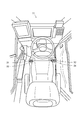
- the figure which shows a crane The figure which shows the inside of a cabin.
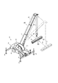
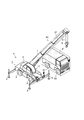
- the figure which shows a 2nd virtual model. The figure which shows the state in which a 1st virtual model and a 2nd virtual model are approaching or interfering.
- the crane 1 is mainly composed of a traveling body 2 and a swing body 3.
- the traveling body 2 includes a pair of left and right front wheels 4 and rear wheels 5.
- the traveling body 2 is provided with an outrigger 6 which is grounded and stabilized when carrying the work of carrying the luggage L.
- the traveling body 2 has a revolving structure 3 supported on the upper portion thereof, which is revolvable by an actuator.
- the revolving structure 3 is equipped with a boom 7 so as to project forward from its rear part. Therefore, the boom 7 is rotatable by an actuator (see arrow A).
- the boom 7 is extendable and contractible by an actuator (see arrow B). Further, the boom 7 can be raised and lowered by an actuator (see arrow C).
- the revolving structure 3 includes a cabin 11 on the side of the boom 7. Inside the cabin 11, a turning lever 31, a telescopic lever 32, a hoisting lever 33, and a winding lever 34 are provided.
- control system 16 will be described with reference to FIG.
- the control system 16 is mainly composed of a controller 20, various levers 31 to 34, and various valves 35 to 38.
- the controller 20 comprises an information storage unit 21 with a ROM.
- the information storage unit 21 stores various programs required for controlling the crane 1.
- the controller 20 constitutes the information processing unit 22 by a CPU, a ROM, a RAM and the like.
- the information processing unit 22 converts the operation amounts of the various levers 31 to 34 into electric signals and transmits the electric signals to the various valves 35 to 38 that operate the actuators. In this way, the controller 20 realizes the operation of the boom 7 (revolving operation/extending/contracting operation/raising/lowering operation) and the operation of the winch 10 (winding operation/unwinding operation).
- the boom 7 can be rotated by an actuator (see arrow A in Fig. 1).
- an actuator is defined as the turning motor 12 (see FIG. 1).
- the turning motor 12 is appropriately operated by a turning valve 35 which is a direction control valve. That is, the turning motor 12 is appropriately operated by the turning valve 35 switching the flow direction of the hydraulic oil.
- the turning valve 35 is operated based on an instruction from the controller 20.
- the turning angle and the turning speed of the boom 7 are detected by a sensor (not shown).
- the boom 7 can be expanded and contracted by an actuator (see arrow B in FIG. 1).
- an actuator is defined as a telescopic cylinder 13 (see FIG. 1).
- the expansion/contraction cylinder 13 is appropriately operated by an expansion/contraction valve 36 which is a directional control valve. That is, the telescopic cylinder 13 is appropriately operated by the telescopic valve 36 switching the flow direction of the hydraulic oil.
- the expansion/contraction valve 36 is operated based on an instruction from the controller 20.
- the extension/contraction length and extension/contraction speed of the boom 7 are detected by a sensor (not shown).
- the boom 7 can be raised and lowered by an actuator (see arrow C in FIG. 1).
- an actuator is defined as a hoisting cylinder 14 (see FIG. 1).
- the hoisting cylinder 14 is appropriately operated by a hoisting valve 37 which is a directional control valve. That is, the undulation cylinder 14 is appropriately operated by the undulation valve 37 switching the flow direction of the hydraulic oil.
- the undulation valve 37 is operated based on an instruction from the controller 20.
- the hoisting angle and hoisting speed of the boom 7 are detected by a sensor (not shown).
- the hook 9 can be raised and lowered by an actuator (see arrow D in FIG. 1).
- an actuator is defined as the winding motor 15 (see FIG. 1).
- the winding motor 15 is appropriately operated by a winding valve 38 which is a directional control valve. That is, the winding motor 15 is appropriately operated by the winding valve 38 switching the flow direction of the hydraulic oil.
- the winding valve 38 is operated based on an instruction from the controller 20.
- the hanging length and the lifting speed of the hook 9 are detected by a sensor (not shown).
- the controller 20 configures the information transmitting/receiving unit 23 with a CPU, a ROM, a RAM, and the like.
- the information transmitting/receiving unit 23 can acquire information from a server computer 24 at a remote place via a communication network. For example, it is possible to obtain information on the possibility that the luggage L collides with the boom 7 that constitutes the revolving structure 3.
- the server computer 24 is functionally integrated with the controller 20 mounted on the crane 1. Therefore, the server computer 24 is considered to be included in the controller 20.
- the controller 20 will be described as a superordinate concept including the server computer 24.
- the first virtual model 40 is a rectangular parallelepiped shape (finite bounding box: Oriented Bounding Box) formed in the virtual space.
- the finite bounding box 41 is formed by three elements of “coordinates of the center point”, “distance from the center point to the plane”, and “direction vector indicating the inclination”.
- the finite bounding box 41 is handled as the boom 7 in the virtual space whose shape is simplified.
- the first virtual model 40 is interlocked with the operation of the boom 7. Specifically, the first virtual model 40 turns in accordance with the turning operation of the boom 7 (see arrow A in FIG. 4 ). Further, the boom 7 expands and contracts in accordance with the expansion and contraction operation (see arrow B in FIG. 4 ). Further, the boom 7 is raised and lowered in accordance with the raising and lowering operation (see arrow C in FIG. 4). Thus, the first virtual model 40 always surrounds the boom 7 in the virtual space regardless of the operation mode of the boom 7.
- the boom 7 may be surrounded by a plurality of finite bounding boxes 41 instead of one finite bounding box 41. For example, the boom 7 may be enclosed by combining a plurality of finite bounding boxes 41.
- the finite boundary box 41 may be enclosed including the other part (the cabin 11 and the like), or the traveling body 2 and the revolving structure 3 may be entirely enclosed by the finite boundary box 41. That is, the range enclosed by the finite bounding box 41 is not limited.
- the second virtual model 50 is created using a rectangular parallelepiped shape (finite bounding box: Oriented Bounding Box) formed in the virtual space.
- the finite bounding box 51 is also formed by three elements of “coordinates of the center point”, “distance from the center point to the plane”, and “direction vector indicating the inclination”.
- the finite bounding box 51 is treated as a luggage L in a virtual space whose shape is simplified.
- the second virtual model 50 is interlocked with the movement of the luggage L. Specifically, the second virtual model 50 moves in accordance with the turning movement of the luggage L (movement by the turning operation of the boom 7) (see arrow A in FIG. 5 ). Further, the luggage L is moved in accordance with the extension/contraction movement (movement by the extension/contraction operation of the boom 7) (see arrow B in FIG. 5 ). Further, the luggage L is moved in accordance with the up-and-down movement (movement by the up-and-down movement of the boom 7) (see arrow C in FIG. 5). In addition, the luggage L is moved in accordance with the winding movement (movement by the winding operation of the winch 10) (see arrow D in FIG. 5 ).
- the second virtual model 50 always surrounds the luggage L in the virtual space regardless of the movement mode of the luggage L.
- the luggage L may be surrounded by a plurality of finite bounding boxes 51 instead of one finite bounding box 51.
- the luggage L may be enclosed by combining a plurality of finite bounding boxes 51.
- only a part of the luggage L may be surrounded by the finite bounding box 51. That is, the range enclosed by the finite boundary box 51 is not limited.
- the controller 20 recognizes the first virtual model 40 and the second virtual model 50 in the virtual space. Therefore, the controller 20 can grasp the actual operation mode of the boom 7 based on the operation of the first virtual model 40. The controller 20 can also grasp the actual movement mode of the luggage L based on the movement of the second virtual model 50. Further, the controller 20 can grasp the relative distance between the boom 7 and the luggage L based on the relative positions of the first virtual model 40 and the second virtual model 50. Therefore, the controller 20 can determine that the luggage L may collide with the boom 7, and if there is a collision, various actuators (a turning motor 12, a telescopic cylinder 13, and a hoisting cylinder 14). The operation of the boom 7 and the operation of the winch 10 are urgently stopped by controlling the winding motor 15).
- various actuators a turning motor 12, a telescopic cylinder 13, and a hoisting cylinder 14
- the present crane 1 includes various actuators (turning motor 12, telescopic cylinder 13, undulating cylinder 14, winding motor 15) and actuators (12.
- the controller 20 moves the first virtual model 40 and the luggage L that are formed so as to include a part or all of the traveling body 2 and the revolving body 3 that are interlocked with each other in accordance with the operations of the traveling body 2 and the revolving body 3.
- the second virtual model 50 formed so as to include the luggage L that is interlocked according to the above is recognized, and when the first virtual model 40 and the second virtual model 50 approach or interfere with each other in the virtual space, the actuator (12.13. Emergency stop the operation of 14 ⁇ 15). According to such a technical idea, it is possible to prevent the luggage L suspended from the hook 9 from colliding with the traveling body 2 and the swing body 3.
- the controller 20 includes the first virtual model 40 formed so as to include the boom 7 that interlocks with the operation of the boom 7 and the luggage L that interlocks with the movement of the luggage L.
- the second virtual model 50 formed so as to include the above when the first virtual model 40 and the second virtual model 50 approach or interfere with each other in the virtual space, the operation of the actuator (12, 13, 14, 15) is performed. Make an emergency stop. According to this technical idea, it is possible to prevent the luggage L suspended by the hook 9 from colliding with the boom 7 forming the revolving structure 3.
- the controller 20 can adopt a simple algorithm in order to realize a high calculation speed while reducing the calculation load. That is, a line segment extending along the longitudinal direction is defined on the boom 7, and when the second virtual model 50 approaches or interferes with the line segment, an actuator (a motor 12 for swiveling, a cylinder 13 for extension/contraction, a cylinder 14 for undulation, a winding operation). The operation of the motor 15) may be stopped in an emergency. Alternatively, a mass point may be defined at the center of the luggage L, and the operation of the actuators (12, 13, 14, 15) may be urgently stopped when the mass point of the first virtual model 40 approaches.
- an actuator a motor 12 for swiveling, a cylinder 13 for extension/contraction, a cylinder 14 for undulation, a winding operation.
- the operation of the motor 15 may be stopped in an emergency.
- a mass point may be defined at the center of the luggage L, and the operation of the actuators (12, 13, 14, 15) may be urgently stopped when the
- a line segment extending along the longitudinal direction of the boom 7 is defined, and a mass point is defined at the center of the load L, and when the line segment and the mass point are close to each other, the operation of the actuator (12, 13, 14, 15) is urgently stopped. You may allow it. Even if it does in this way, the same effect will be produced.
- FIG. (X) of FIG. 7 is an enlarged view of the second virtual model 50 as seen from the direction of arrow V in the drawing.
- the second virtual model 50 has a cylindrical shape obtained by rotating the finite bounding box 51.
- the rotating shaft at this time is the first shaft 52 passing through the hook 9 from the tip portion of the boom 7. Therefore, the second virtual model 50 has a columnar shape that includes the region R when the luggage L rotates about the first axis 52.
- the radius r and the height h of the second virtual model 50 satisfy the following relational expressions (1) and (2). r ⁇ x ⁇ 2...(1) h ⁇ z (2)
- the second virtual model 50 when the straight line passing from the tip of the boom 7 and passing through the hook 9 is used as the first axis 52, the second virtual model 50 includes the region R when the load L rotates about the first axis 52. It has a cylindrical shape. According to this technical idea, since the possibility of collision due to the rotation of the luggage L is taken into consideration, the luggage L hung from the hook 9 collides with the traveling body 2 and the revolving structure 3 (the boom 7 forming the revolving structure 3). You can surely prevent it.
- FIG. (X) of FIG. 8 is an enlarged view of the second virtual model 50 seen from the direction of arrow V in the figure.
- the second virtual model 50 has a cylindrical shape obtained by swinging and rotating the finite bounding box 51.
- the rotation axis at this time is the second vertical axis 53 passing through the lowest point P of the locus T of the load L when the load L is performing the pendulum motion. Therefore, in the second virtual model 50, the luggage L at the position farthest from the second shaft 53 about the second shaft 53 rotates about the first shaft 52 and makes a large rotation (about the second shaft 53). It has a columnar shape that encloses the region R when the rotation is performed.
- the radius r of the second virtual model 50 is The height h satisfies the following relational expressions (1) and (2). r ⁇ (s+z) ⁇ sin ⁇ +x/2 ⁇ cos ⁇ (1) h ⁇ z+x ⁇ sin ⁇ /2+s ⁇ s ⁇ cos ⁇ (2)
- the second virtual model 50 is the second It has a columnar shape that encloses a region R when the luggage L, which is located farthest from the second shaft 53 about the shaft 53, makes a large rotation while rotating about the first shaft 52.
- the luggage L suspended by the hook 9 is the traveling body 2 or the revolving structure 3 (the boom 7 forming the revolving structure 3). Can be more reliably prevented from colliding with.
- the size of the second virtual model 50 is adjusted according to the suspension length s. Furthermore, since the possibility of collision is considered according to the suspension length s, it is possible to prevent the luggage L suspended by the hooks 9 from colliding with the traveling body 2 and the revolving structure 3 (the boom 7 forming the revolving structure 3). It can be prevented more reliably.
- FIG. (X) of FIG. 9 is an enlarged view of the second virtual model 50 as seen from the direction of arrow V in the figure.
- the second virtual model 50 has a shape in which a conical shape is added to the cylindrical shape obtained by swinging and rotating the finite bounding box 51.
- the columnar shape refers to a large rotation (rotation that grinds around the second shaft 53) while rotating around the second shaft 53 and the luggage L that is located farthest from the second shaft 53 while rotating around the first shaft 52. )
- the region R at the time of doing) is included.
- the conical shape includes a region Rc when the wire L is rotated about the second shaft 53 with the wire rope 8 when the load L is at the farthest position from the second shaft 53 as the generatrix G.
- the second virtual model 50 has a shape in which the conical shape having the wire rope 8 as the generatrix G is added to the upper part of the cylindrical shape. According to this technical idea, the possibility of collision due to shake and rotation is taken into consideration even for the structure above the luggage L, so that the luggage L hung on the hook 9 is a structure such as another hook 17. Can be prevented from colliding with.
- FIG. 10 is a first application example and shows a state in which the first virtual model 40 and the third virtual model 60 are in proximity or interfere with each other.
- the first application example is to prevent the boom 7 from colliding with the obstacle F.
- the obstacle F needs to be surrounded by the third virtual model 60.
- the third virtual model 60 is created using a rectangular parallelepiped shape (finite bounding box: Oriented Bounding Box) formed in the virtual space.
- the finite bounding box 61 is treated as an obstacle F in a virtual space whose shape is simplified.
- the third virtual model 60 is interlocked with the operation of the obstacle F.
- the obstacle F may be surrounded by a plurality of finite bounding boxes 61 instead of one finite bounding box 61.
- the obstacle F may be surrounded by combining a plurality of finite bounding boxes 61.
- the finite bounding box 61 may surround only part of the obstacle F.
- the controller 20 recognizes the first virtual model 40 and the third virtual model 60 in the virtual space. Therefore, the controller 20 can grasp the actual operation mode of the boom 7 based on the operation of the first virtual model 40. Further, the controller 20 can grasp the operation mode of the actual obstacle F based on the operation of the third virtual model 60. Further, the controller 20 can grasp the relative distance between the boom 7 and the obstacle F based on the relative positions of the first virtual model 40 and the third virtual model 60. Therefore, the controller 20 can determine that the boom 7 may collide with the obstacle F, and if there is a collision, various actuators (a swing motor 12, a telescopic cylinder 13, an undulating cylinder 14, By controlling the winding motor 15), the operation of the boom 7 and the operation of the winch 10 are urgently stopped.
- various actuators a swing motor 12, a telescopic cylinder 13, an undulating cylinder 14, By controlling the winding motor 15
- the controller 20 controls the first virtual model 40 formed so as to include the boom 7 that interlocks with the operation of the boom 7 and the obstacle F that interlocks with the movement of the obstacle F. Recognizing the third virtual model 60 formed so as to include it, and when the first virtual model 40 and the third virtual model 50 approach or interfere with each other in the virtual space, the operation of the actuator (12, 13, 14, 15) is urgently performed. Stop. According to this technical idea, it is possible to prevent the boom 7 from colliding with the obstacle F.
- FIG. 11 is a second application example and shows a state in which the second virtual model 50 and the fourth virtual model 70 are in proximity or interfere with each other.
- the second application example is to prevent the luggage L from colliding with the obstacle F. Even in the second application example, the obstacle F needs to be surrounded by the fourth virtual model 70.
- the fourth virtual model 70 is created using a rectangular parallelepiped shape (finite bounding box: Oriented Bounding Box) formed in the virtual space.
- the finite bounding box 71 is handled as an obstacle F in a virtual space whose shape is simplified.
- the fourth virtual model 70 is interlocked with the operation of the obstacle F.
- the obstacle F may be surrounded by a plurality of finite boundary boxes 71 instead of one finite boundary box 71.
- the obstacle F may be enclosed by combining a plurality of finite bounding boxes 71.
- the finite bounding box 71 may surround only part of the obstacle F.
- the controller 20 recognizes the second virtual model 50 and the fourth virtual model 70 in the virtual space. Therefore, the controller 20 can grasp the actual movement mode of the luggage L based on the movement of the second virtual model 50. Further, the controller 20 can grasp the actual operation mode of the obstacle F based on the operation of the fourth virtual model 70. Further, the controller 20 can grasp the relative distance between the luggage L and the obstacle F based on the relative positions of the second virtual model 50 and the fourth virtual model 70. Therefore, the controller 20 can determine that the luggage L may collide with the obstacle F, and if there is a collision, various actuators (a turning motor 12, a telescopic cylinder 13, an undulating cylinder 14, By controlling the winding motor 15), the operation of the boom 7 and the operation of the winch 10 are urgently stopped.
- various actuators a turning motor 12, a telescopic cylinder 13, an undulating cylinder 14, By controlling the winding motor 15
- the controller 20 controls the second virtual model 50 that is formed so as to include the luggage L that interlocks with the operation of the luggage L and the obstacle F that interlocks with the movement of the obstacle F. Recognizing the fourth virtual model 70 formed so as to include it, and when the second virtual model 50 and the third virtual model 50 approach or interfere in the virtual space, the operation of the actuator (12, 13, 14, 15) is urgently performed. Stop. According to this technical idea, it is possible to prevent the luggage L from colliding with the obstacle F.
- the technical idea disclosed in the present application has a so-called jib and can be applied to a structure in which the boom 7 is extended by the jib. That is, the jib is included in the boom 7 as a component of the boom 7. Further, the technical idea disclosed in the present application utilizes a finite bounding box: Oriented Bounding Box as a rectangular parallelepiped shape. However, an axis-parallel bounding box: Axis-Aligned Bounding Box may also be used as the rectangular parallelepiped shape.
- the bounding box Since the sides of the rectangular parallelepiped shape of the axis-parallel bounding box are parallel to the XYZ axes, the bounding box must be larger than the finite bounding box, and the judgment becomes rough when considering the possibility of collision. On the other hand, there is an advantage that the calculation load can be reduced.
- the present invention can be used for a crane that can prevent a load suspended on a hook from colliding with a traveling body or a revolving structure.
Landscapes
- Engineering & Computer Science (AREA)
- Mechanical Engineering (AREA)
- Jib Cranes (AREA)
- Control And Safety Of Cranes (AREA)
Abstract
フックに吊り下げられた荷物が走行体や旋回体に衝突するのを防ぐことができるクレーンを提供することを課題とする。荷物(L)の運搬に供する各種のアクチュエータ(12・13・14・15)と、アクチュエータ(12・13・14・15)の稼動を指示するコントローラ(20)と、を具備し、コントローラ(20)は、走行体(2)及び旋回体(3)の動作に合わせて連動する走行体(2)及び旋回体(3)の一部若しくは全部を内包するように形成された第一仮想モデル(40)及び荷物(L)の移動に合わせて連動する荷物(L)を内包するように形成された第二仮想モデル(50)を認識し、仮想空間上で第一仮想モデル(40)と第二仮想モデル(50)が近接又は干渉するとアクチュエータ(12・13・14・15)の稼動を緊急停止させる。
Description
本発明は、フックに吊り下げられた荷物が走行体や旋回体に衝突するのを防ぐことができるクレーンに関する。
従来より、代表的な作業車両であるクレーンが知られている。クレーンは、主に走行体と旋回体で構成されている。走行体は、複数の車輪を備え、自走可能としている。旋回体は、ブームのほかにワイヤロープやフックを備え、荷物を吊り下げた状態でこれを運搬可能としている。
ところで、フックに吊り下げられた荷物は、ブームの先端部分を支点として振子運動を行うことがある(特許文献1参照)。また、フックに吊り下げられた荷物は、ブームの先端部分からフックを通る直線を中心として回転運動を行うことがある(特許文献2参照)。そのため、ブームの姿勢やワイヤロープの吊下長さ、荷物の形状などにより、荷物が走行体や旋回体に衝突してしまうおそれがあった。そこで、フックに吊り下げられた荷物が走行体や旋回体に衝突するのを防ぐことができるクレーンが求められていた。
フックに吊り下げられた荷物が走行体や旋回体に衝突するのを防ぐことができるクレーンを提供する。
本発明のクレーンにおいては、走行体と、前記走行体に支持される旋回体と、を備え、
前記旋回体がブームと当該ブームの先端部分から垂下するワイヤロープと当該ワイヤロープの巻き入れ及び巻き出しによって昇降するフックを有しており、前記フックに荷物を吊り下げた状態で当該荷物を運搬するクレーンにおいて、前記荷物の運搬に供する各種のアクチュエータと、前記アクチュエータの稼動を指示するコントローラと、を具備し、前記コントローラは、前記走行体及び前記旋回体の動作に合わせて連動する当該走行体及び当該旋回体の一部若しくは全部を内包するように形成された第一仮想モデル及び前記荷物の移動に合わせて連動する当該荷物を内包するように形成された第二仮想モデルを認識し、仮想空間上で前記第一仮想モデルと前記第二仮想モデルが近接又は干渉すると前記アクチュエータの稼動を緊急停止させる、ものである。
前記旋回体がブームと当該ブームの先端部分から垂下するワイヤロープと当該ワイヤロープの巻き入れ及び巻き出しによって昇降するフックを有しており、前記フックに荷物を吊り下げた状態で当該荷物を運搬するクレーンにおいて、前記荷物の運搬に供する各種のアクチュエータと、前記アクチュエータの稼動を指示するコントローラと、を具備し、前記コントローラは、前記走行体及び前記旋回体の動作に合わせて連動する当該走行体及び当該旋回体の一部若しくは全部を内包するように形成された第一仮想モデル及び前記荷物の移動に合わせて連動する当該荷物を内包するように形成された第二仮想モデルを認識し、仮想空間上で前記第一仮想モデルと前記第二仮想モデルが近接又は干渉すると前記アクチュエータの稼動を緊急停止させる、ものである。
本発明のクレーンにおいては、前記コントローラは、前記ブームの動作に合わせて連動する当該ブームを内包するように形成された第一仮想モデル及び前記荷物の移動に合わせて連動する当該荷物を内包するように形成された第二仮想モデルを認識し、仮想空間上で前記第一仮想モデルと前記第二仮想モデルが近接又は干渉すると前記アクチュエータの稼動を緊急停止させる、ものである。
本発明のクレーンにおいては、前記ブームの先端部分から前記フックを通る直線を第一軸とした場合、前記第二仮想モデルは、前記第一軸を中心として前記荷物が回転したときの領域を内包する円柱形状となっている、ものである。
本発明のクレーンにおいては、前記荷物が振子運動をしている際における当該荷物の軌跡の最下点を通る鉛直方向の直線を第二軸とした場合、前記第二仮想モデルは、前記第二軸を中心として当該第二軸から最も離れた位置にある前記荷物が前記第一軸を中心に回転しながら大回転したときの領域を内包する円柱形状となっている、ものである。
本発明のクレーンにおいては、前記第二仮想モデルは、前記ワイヤロープを母線とする円錐形状を前記円柱形状の上部に付加した形状となっている、ものである。
本発明のクレーンによれば、荷物の運搬に供する各種のアクチュエータと、アクチュエータの稼動を指示するコントローラと、を具備している。そして、コントローラは、走行体及び旋回体の動作に合わせて連動する走行体及び旋回体の一部若しくは全部を内包するように形成された第一仮想モデル及び荷物の移動に合わせて連動する荷物を内包するように形成された第二仮想モデルを認識し、仮想空間上で第一仮想モデルと第二仮想モデルが近接又は干渉するとアクチュエータの稼動を緊急停止させる。かかる技術的思想によれば、フックに吊り下げられた荷物が走行体や旋回体に衝突するのを防ぐことができる。
本発明のクレーンによれば、コントローラは、ブームの動作に合わせて連動するブームを内包するように形成された第一仮想モデル及び荷物の移動に合わせて連動する荷物を内包するように形成された第二仮想モデルを認識し、仮想空間上で第一仮想モデルと第二仮想モデルが近接又は干渉するとアクチュエータの稼動を緊急停止させる。かかる技術的思想によれば、フックに吊り下げられた荷物が旋回体を構成するブームに衝突するのを防ぐことができる。
本発明のクレーンによれば、ブームの先端部分からフックを通る直線を第一軸とした場合、第二仮想モデルは、第一軸を中心として荷物が回転したときの領域を内包する円柱形状となっている。かかる技術的思想によれば、荷物の回転による衝突可能性を考慮するので、フックに吊り下げられた荷物が走行体や旋回体(旋回体を構成するブーム)に衝突するのを確実に防ぐことができる。
本発明のクレーンによれば、荷物が振子運動をしている際における荷物の軌跡の最下点を通る鉛直方向の直線を第二軸とした場合、第二仮想モデルは、第二軸を中心として第二軸から最も離れた位置にある荷物が第一軸を中心に回転しながら大回転したときの領域を内包する円柱形状となっている。かかる技術的思想によれば、荷物の振れと回転による衝突可能性を考慮するので、フックに吊り下げられた荷物が走行体や旋回体(旋回体を構成するブーム)に衝突するのをより確実に防ぐことができる。
本発明のクレーンによれば、第二仮想モデルは、ワイヤロープを母線とする円錐形状を円柱形状の上部に付加した形状となっている。かかる技術的思想によれば、荷物の上方にある構造物に対しても振れと回転による衝突可能性を考慮するので、フックに吊り下げられた荷物が他のフックなどの構造物に衝突するのを防ぐことができる。
本願に開示する技術的思想は、以下に説明するクレーン1のほか、他のクレーンにも適用できる。
まず、図1及び図2を用いて、クレーン1について説明する。
クレーン1は、主に走行体2と旋回体3で構成されている。
走行体2は、左右一対の前輪4と後輪5を備えている。また、走行体2は、荷物Lの運搬作業を行う際に接地させて安定を図るアウトリガ6を備えている。なお、走行体2は、アクチュエータによって、その上部に支持する旋回体3を旋回自在としている。
旋回体3は、その後部から前方へ突き出すようにブーム7を備えている。そのため、ブーム7は、アクチュエータによって旋回自在となっている(矢印A参照)。また、ブーム7は、アクチュエータによって伸縮自在となっている(矢印B参照)。更に、ブーム7は、アクチュエータによって起伏自在となっている(矢印C参照)。
加えて、ブーム7には、ワイヤロープ8が架け渡されている。ブーム7の先端部分から垂下するワイヤロープ8には、フック9が取り付けられている。また、ブーム7の基端側近傍には、ウインチ10が配置されている。ウインチ10は、アクチュエータと一体的に構成されており、ワイヤロープ8の巻き入れ及び巻き出しを可能としている。そのため、フック9は、アクチュエータによって昇降自在となっている(矢印D参照)。なお、旋回体3は、ブーム7の側方にキャビン11を備えている。キャビン11の内部には、旋回レバー31や伸縮レバー32、起伏レバー33、巻回レバー34が設けられている。
次に、図3を用いて、操縦システム16について説明する。
操縦システム16は、主にコントローラ20と各種レバー31~34と各種バルブ35~38で構成されている。
コントローラ20は、ROMによって情報記憶部21を構成している。情報記憶部21は、クレーン1の制御に要する様々なプログラムが記憶されている。
また、コントローラ20は、CPUやROM、RAMなどによって情報処理部22を構成している。情報処理部22は、各種レバー31~34の操作量を電気信号に変換し、アクチュエータを稼動させる各種バルブ35~38へ送信する。こうして、コントローラ20は、ブーム7の稼動(旋回動作・伸縮動作・起伏動作)及びウインチ10の稼動(巻入動作・巻出動作)を実現する。
詳しく説明すると、ブーム7は、アクチュエータによって旋回自在となっている(図1における矢印A参照)。本願においては、かかるアクチュエータを旋回用モーター12と定義する(図1参照)。旋回用モーター12は、方向制御弁である旋回用バルブ35によって適宜に稼動される。つまり、旋回用モーター12は、旋回用バルブ35が作動油の流動方向を切り替えることで適宜に稼動される。なお、旋回用バルブ35は、コントローラ20の指示に基づいて稼動される。ブーム7の旋回角度や旋回速度は、図示しないセンサによって検出される。
また、ブーム7は、アクチュエータによって伸縮自在となっている(図1における矢印B参照)。本願においては、かかるアクチュエータを伸縮用シリンダ13と定義する(図1参照)。伸縮用シリンダ13は、方向制御弁である伸縮用バルブ36によって適宜に稼動される。つまり、伸縮用シリンダ13は、伸縮用バルブ36が作動油の流動方向を切り替えることで適宜に稼動される。なお、伸縮用バルブ36は、コントローラ20の指示に基づいて稼動される。ブーム7の伸縮長さや伸縮速度は、図示しないセンサによって検出される。
更に、ブーム7は、アクチュエータによって起伏自在となっている(図1における矢印C参照)。本願においては、かかるアクチュエータを起伏用シリンダ14と定義する(図1参照)。起伏用シリンダ14は、方向制御弁である起伏用バルブ37によって適宜に稼動される。つまり、起伏用シリンダ14は、起伏用バルブ37が作動油の流動方向を切り替えることで適宜に稼動される。なお、起伏用バルブ37は、コントローラ20の指示に基づいて稼動される。ブーム7の起伏角度や起伏速度は、図示しないセンサによって検出される。
更に、フック9は、アクチュエータによって昇降自在となっている(図1における矢印D参照)。本願においては、かかるアクチュエータを巻回用モーター15と定義する(図1参照)。巻回用モーター15は、方向制御弁である巻回用バルブ38によって適宜に稼動される。つまり、巻回用モーター15は、巻回用バルブ38が作動油の流動方向を切り替えることで適宜に稼動される。なお、巻回用バルブ38は、コントローラ20の指示に基づいて稼動される。フック9の吊下長さや昇降速度は、図示しないセンサによって検出される。
加えて、コントローラ20は、CPUやROM、RAMなどによって情報送受信部23を構成している。情報送受信部23は、通信ネットワークを経由して遠隔地にあるサーバーコンピュータ24から情報を取得できる。例えば、旋回体3を構成するブーム7に対して荷物Lが衝突する可能性についての情報を取得することができる。なお、サーバーコンピュータ24は、クレーン1に搭載されたコントローラ20と機能として一体をなす。従って、サーバーコンピュータ24は、コントローラ20に含まれるとも考えられる。以下では、サーバーコンピュータ24を含む上位概念としてコントローラ20を説明する。
次に、図4を用いて、第一仮想モデル40について説明する。
第一仮想モデル40は、仮想空間上に形成された直方体形状(有限境界ボックス:Oriented Bounding Box)である。かかる有限境界ボックス41は、「中心点の座標」と「中心点から平面までの距離」と「傾きを表す方向ベクトル」の三つの要素によって形成されている。有限境界ボックス41は、形状を単純化した仮想空間上のブーム7として取り扱われる。
第一仮想モデル40は、ブーム7の動作に合わせて連動する。具体的に説明すると、第一仮想モデル40は、ブーム7の旋回動作に合わせて旋回する(図4における矢印A参照)。また、ブーム7の伸縮動作に合わせて伸縮する(図4における矢印B参照)。更に、ブーム7の起伏動作に合わせて起伏する(図4における矢印C参照)。こうして、第一仮想モデル40は、ブーム7の動作態様に関わらず、仮想空間上にて常にブーム7を囲っている。なお、一つの有限境界ボックス41ではなく、複数の有限境界ボックス41によってブーム7を囲うとしてもよい。例えば、複数の有限境界ボックス41を組み合わせてブーム7を囲うとしてもよい。また、その他の一部(キャビン11など)を含めて有限境界ボックス41で囲うとしてもよいし、走行体2や旋回体3の全部を有限境界ボックス41で囲うとしてもよい。即ち、有限境界ボックス41で囲う範囲を限定するものではない。
次に、図5を用いて、第二仮想モデル50について説明する。
第二仮想モデル50は、仮想空間上に形成された直方体形状(有限境界ボックス:Oriented Bounding Box)を用いて作成される。かかる有限境界ボックス51も、「中心点の座標」と「中心点から平面までの距離」と「傾きを表す方向ベクトル」の三つの要素によって形成されている。有限境界ボックス51は、形状を単純化した仮想空間上の荷物Lとして取り扱われる。
第二仮想モデル50は、荷物Lの移動に合わせて連動する。具体的に説明すると、第二仮想モデル50は、荷物Lの旋回移動(ブーム7の旋回動作による移動)に合わせて移動する(図5における矢印A参照)。また、荷物Lの伸縮移動(ブーム7の伸縮動作による移動)に合わせて移動する(図5における矢印B参照)。更に、荷物Lの起伏移動(ブーム7の起伏動作による移動)に合わせて移動する(図5における矢印C参照)。加えて、荷物Lの巻回移動(ウインチ10の巻回動作による移動)に合わせて移動する(図5における矢印D参照)。こうして、第二仮想モデル50は、荷物Lの移動態様に関わらず、仮想空間上にて常に荷物Lを囲っている。なお、一つの有限境界ボックス51ではなく、複数の有限境界ボックス51によって荷物Lを囲うとしてもよい。例えば、複数の有限境界ボックス51を組み合わせて荷物Lを囲うとしてもよい。また、荷物Lの一部のみを有限境界ボックス51で囲うとしてもよい。即ち、有限境界ボックス51で囲う範囲を限定するものではない。
次に、図6を用いて、第一仮想モデル40と第二仮想モデル50が近接又は干渉をしている状態について説明する。ここでは、ブーム7の起立動作により、ブーム7に荷物Lが近づいている状況を想定して説明する(図6における矢印E参照)。
コントローラ20は、仮想空間上における第一仮想モデル40と第二仮想モデル50を認識している。このため、コントローラ20は、第一仮想モデル40の動作に基づいて現実のブーム7の動作態様を把握できる。また、コントローラ20は、第二仮想モデル50の移動に基づいて現実の荷物Lの移動態様を把握できる。更に、コントローラ20は、第一仮想モデル40と第二仮想モデル50の相対位置に基づいてブーム7と荷物Lの相対距離を把握できる。従って、コントローラ20は、ブーム7に対して荷物Lが衝突する恐れがあることを判断でき、衝突する恐れがある場合は、各種のアクチュエータ(旋回用モーター12・伸縮用シリンダ13・起伏用シリンダ14・巻回用モーター15)を制御してブーム7の稼動及びウインチ10の稼動を緊急停止させるのである。
以上のように、本クレーン1は、荷物Lの運搬に供する各種のアクチュエータ(旋回用モーター12・伸縮用シリンダ13・起伏用シリンダ14・巻回用モーター15)と、アクチュエータ(12・13・14・15)の稼動を指示するコントローラ20と、を具備している。そして、コントローラ20は、走行体2及び旋回体3の動作に合わせて連動する走行体2及び旋回体3の一部若しくは全部を内包するように形成された第一仮想モデル40及び荷物Lの移動に合わせて連動する荷物Lを内包するように形成された第二仮想モデル50を認識し、仮想空間上で第一仮想モデル40と第二仮想モデル50が近接又は干渉するとアクチュエータ(12・13・14・15)の稼動を緊急停止させる。かかる技術的思想によれば、フック9に吊り下げられた荷物Lが走行体2や旋回体3に衝突するのを防ぐことができる。
詳細に説明すると、本クレーン1において、コントローラ20は、ブーム7の動作に合わせて連動するブーム7を内包するように形成された第一仮想モデル40及び荷物Lの移動に合わせて連動する荷物Lを内包するように形成された第二仮想モデル50を認識し、仮想空間上で第一仮想モデル40と第二仮想モデル50が近接又は干渉するとアクチュエータ(12・13・14・15)の稼動を緊急停止させる。かかる技術的思想によれば、フック9に吊り下げられた荷物Lが旋回体3を構成するブーム7に衝突するのを防ぐことができる。
ところで、コントローラ20は、計算負荷を減らしつつ高い計算速度を実現するため、簡素なアルゴリズムを採用することが可能である。即ち、ブーム7に長手方向に沿って延びる線分を定義し、かかる線分に第二仮想モデル50が近接又は干渉するとアクチュエータ(旋回用モーター12・伸縮用シリンダ13・起伏用シリンダ14・巻回用モーター15)の稼動を緊急停止させるとしてもよい。或いは、荷物Lの中心に質点を定義し、第一仮想モデル40にかかる質点が近接するとアクチュエータ(12・13・14・15)の稼動を緊急停止させるとしてもよい。或いは、ブーム7に長手方向に沿って延びる線分を定義するとともに荷物Lの中心に質点を定義し、かかる線分と質点が近接するとアクチュエータ(12・13・14・15)の稼動を緊急停止させるとしてもよい。このようにしても、同様の効果を奏することとなる。
次に、図7を用いて、一の実施形態に係る第二仮想モデル50について詳しく説明する。図7の(X)は、第二仮想モデル50を図中における矢印Vの方向から見た拡大図である。
本実施形態に係る第二仮想モデル50は、有限境界ボックス51の回転によって得られる円柱形状となっている。このときの回転軸は、ブーム7の先端部分からフック9を通る第一軸52である。そのため、第二仮想モデル50は、第一軸52を中心として荷物Lが回転したときの領域Rを内包する円柱形状となっている。なお、長さがxで高さがzである直方体形状の荷物Lを想定すると、第二仮想モデル50の半径rと高さhは下記(1)(2)の関係式を満たす。
r≧x÷2・・・(1)
h≧z・・・・・(2)
r≧x÷2・・・(1)
h≧z・・・・・(2)
このように、ブーム7の先端部分からフック9を通る直線を第一軸52とした場合、第二仮想モデル50は、第一軸52を中心として荷物Lが回転したときの領域Rを内包する円柱形状となっている。かかる技術的思想によれば、荷物Lの回転による衝突可能性を考慮するので、フック9に吊り下げられた荷物Lが走行体2や旋回体3(旋回体3を構成するブーム7)に衝突するのを確実に防ぐことができる。
次に、図8を用いて、他の実施形態に係る第二仮想モデル50について詳しく説明する。図8の(X)は、第二仮想モデル50を図中における矢印Vの方向から見た拡大図である。
本実施形態に係る第二仮想モデル50は、有限境界ボックス51の振れと回転によって得られる円柱形状となっている。このときの回転軸は、荷物Lが振子運動をしている際における当該荷物Lの軌跡Tの最下点Pを通る鉛直方向の第二軸53である。そのため、第二仮想モデル50は、第二軸53を中心として当該第二軸53から最も離れた位置にある荷物Lが第一軸52を中心に回転しながら大回転(第二軸53を中心にグラインドする回転を指す)したときの領域Rを内包する円柱形状となっている。なお、荷物Lの吊下長さをsとし振れ角度をθとした場合において、長さがxで高さがzである直方体形状の荷物Lを想定すると、第二仮想モデル50の半径rと高さhは下記(1)(2)の関係式を満たす。
r≧(s+z)×sinθ+x÷2×cosθ・・・(1)
h≧z+x×sinθ÷2+s-s×cosθ・・・(2)
r≧(s+z)×sinθ+x÷2×cosθ・・・(1)
h≧z+x×sinθ÷2+s-s×cosθ・・・(2)
このように、荷物Lが振子運動をしている際における当該荷物Lの軌跡Tの最下点Pを通る鉛直方向の直線を第二軸53とした場合、第二仮想モデル50は、第二軸53を中心として当該第二軸53から最も離れた位置にある荷物Lが第一軸52を中心に回転しながら大回転したときの領域Rを内包する円柱形状となっている。かかる技術的思想によれば、荷物Lの振れと回転による衝突可能性を考慮するので、フック9に吊り下げられた荷物Lが走行体2や旋回体3(旋回体3を構成するブーム7)に衝突するのをより確実に防ぐことができる。
この点、振子運動の振れ量は、荷物Lの吊下長さsによって変化することから、吊下長さsに応じて第二仮想モデル50の大きさが調節されることとなる。ひいては、吊下長さsに応じて衝突可能性を考慮するので、フック9に吊り下げられた荷物Lが走行体2や旋回体3(旋回体3を構成するブーム7)に衝突するのをより確実に防ぐことができる。
次に、図9を用いて、他の実施形態に係る第二仮想モデル50について詳しく説明する。図9の(X)は、第二仮想モデル50を図中における矢印Vの方向から見た拡大図である。
本実施形態に係る第二仮想モデル50は、有限境界ボックス51の振れと回転によって得られる円柱形状に円錐形状を付加した形状となっている。円柱形状は、第二軸53を中心として当該第二軸53から最も離れた位置にある荷物Lが第一軸52を中心に回転しながら大回転(第二軸53を中心にグラインドする回転を指す)したときの領域Rを内包する。円錐形状は、荷物Lが第二軸53から最も離れた位置にあるときのワイヤロープ8を母線Gとして第二軸53を中心に回転したときの領域Rcを内包する。
このように、第二仮想モデル50は、ワイヤロープ8を母線Gとする円錐形状を円柱形状の上部に付加した形状となっている。かかる技術的思想によれば、荷物Lの上方にある構造物に対しても振れと回転による衝突可能性を考慮するので、フック9に吊り下げられた荷物Lが他のフック17などの構造物に衝突するのを防ぐことができる。
次に、本願に開示する技術的思想の第一の応用事例について説明する。図10は、第一の応用事例であって第一仮想モデル40と第三仮想モデル60が近接又は干渉をしている状態を示している。
第一の応用事例は、ブーム7が障害物Fに衝突するのを防ぐものである。第一の応用事例にあっては、障害物Fが第三仮想モデル60によって囲われている必要がある。
第三仮想モデル60は、仮想空間上に形成された直方体形状(有限境界ボックス:Oriented Bounding Box)を用いて作成される。有限境界ボックス61は、形状を単純化した仮想空間上の障害物Fとして取り扱われる。第三仮想モデル60は、障害物Fが車両などであって移動自在である場合は、障害物Fの動作に合わせて連動する。なお、一つの有限境界ボックス61ではなく、複数の有限境界ボックス61によって障害物Fを囲うとしてもよい。例えば、複数の有限境界ボックス61を組み合わせて障害物Fを囲うとしてもよい。障害物Fの一部のみを有限境界ボックス61で囲うとしてもよい。
コントローラ20は、仮想空間上における第一仮想モデル40と第三仮想モデル60を認識している。このため、コントローラ20は、第一仮想モデル40の動作に基づいて現実のブーム7の動作態様を把握できる。また、コントローラ20は、第三仮想モデル60の動作に基づいて現実の障害物Fの動作態様を把握できる。更に、コントローラ20は、第一仮想モデル40と第三仮想モデル60の相対位置に基づいてブーム7と障害物Fの相対距離を把握できる。従って、コントローラ20は、ブーム7が障害物Fに衝突する恐れがあることを判断でき、衝突する恐れがある場合は、各種のアクチュエータ(旋回用モーター12・伸縮用シリンダ13・起伏用シリンダ14・巻回用モーター15)を制御してブーム7の稼動及びウインチ10の稼動を緊急停止させるのである。
以上のように、コントローラ20は、ブーム7の動作に合わせて連動する当該ブーム7を内包するように形成された第一仮想モデル40及び障害物Fの移動に合わせて連動する当該障害物Fを内包するように形成された第三仮想モデル60を認識し、仮想空間上で第一仮想モデル40と第三仮想モデル50が近接又は干渉するとアクチュエータ(12・13・14・15)の稼動を緊急停止させる。かかる技術的思想によれば、ブーム7が障害物Fに衝突するのを防ぐことができる。
次に、本願に開示する技術的思想の第二の応用事例について説明する。図11は、第二の応用事例であって第二仮想モデル50と第四仮想モデル70が近接又は干渉をしている状態を示している。
第二の応用事例は、荷物Lが障害物Fに衝突するのを防ぐものである。第二の応用事例にあっても、障害物Fが第四仮想モデル70によって囲われている必要がある。
第四仮想モデル70は、仮想空間上に形成された直方体形状(有限境界ボックス:Oriented Bounding Box)を用いて作成される。有限境界ボックス71は、形状を単純化した仮想空間上の障害物Fとして取り扱われる。第四仮想モデル70は、障害物Fが車両などであって移動自在である場合は、障害物Fの動作に合わせて連動する。なお、一つの有限境界ボックス71ではなく、複数の有限境界ボックス71によって障害物Fを囲うとしてもよい。例えば、複数の有限境界ボックス71を組み合わせて障害物Fを囲うとしてもよい。障害物Fの一部のみを有限境界ボックス71で囲うとしてもよい。
コントローラ20は、仮想空間上における第二仮想モデル50と第四仮想モデル70を認識している。このため、コントローラ20は、第二仮想モデル50の移動に基づいて現実の荷物Lの移動態様を把握できる。また、コントローラ20は、第四仮想モデル70の動作に基づいて現実の障害物Fの動作態様を把握できる。更に、コントローラ20は、第二仮想モデル50と第四仮想モデル70の相対位置に基づいて荷物Lと障害物Fの相対距離を把握できる。従って、コントローラ20は、荷物Lが障害物Fに衝突する恐れがあることを判断でき、衝突する恐れがある場合は、各種のアクチュエータ(旋回用モーター12・伸縮用シリンダ13・起伏用シリンダ14・巻回用モーター15)を制御してブーム7の稼動及びウインチ10の稼動を緊急停止させるのである。
以上のように、コントローラ20は、荷物Lの動作に合わせて連動する当該荷物Lを内包するように形成された第二仮想モデル50及び障害物Fの移動に合わせて連動する当該障害物Fを内包するように形成された第四仮想モデル70を認識し、仮想空間上で第二仮想モデル50と第三仮想モデル50が近接又は干渉するとアクチュエータ(12・13・14・15)の稼動を緊急停止させる。かかる技術的思想によれば、荷物Lが障害物Fに衝突するのを防ぐことができる。
最後に、本願に開示する技術的思想は、いわゆるジブを備えており、ジブによってブーム7が延長される構造に対しても適用可能である。つまり、ジブは、ブーム7の構成要素としてブーム7に含まれるものとする。また、本願に開示する技術的思想は、直方体形状として有限境界ボックス:Oriented Bounding Boxを利用するものである。しかしながら、同じく直方体形状として軸並行境界ボックス:Axis-Aligned Bounding Boxを利用するとしてもよい。軸並行境界ボックスは、直方体形状の各辺がXYZ軸に並行なので、有限境界ボックスよりも大きくならざるを得ず、衝突可能性を考慮するにあたって判断が粗くなる。一方で、計算負荷を減らすことができるという利点を有する。
本発明は、フックに吊り下げられた荷物が走行体や旋回体に衝突するのを防ぐことができるクレーンに利用可能である。
1 クレーン
2 走行体
3 旋回体
7 ブーム
8 ワイヤロープ
9 フック
10 ウインチ
12 旋回用モーター(アクチュエータ)
13 伸縮用シリンダ(アクチュエータ)
14 起伏用シリンダ(アクチュエータ)
15 巻回用モーター(アクチュエータ)
20 コントローラ
21 情報記憶部
22 情報処理部
23 情報受信部
24 サーバーコンピュータ
40 第一仮想モデル
41 有限境界ボックス
50 第二仮想モデル
51 有限境界ボックス
52 第一軸
53 第二軸
G 母線
L 荷物
P 最下点
R 領域
2 走行体
3 旋回体
7 ブーム
8 ワイヤロープ
9 フック
10 ウインチ
12 旋回用モーター(アクチュエータ)
13 伸縮用シリンダ(アクチュエータ)
14 起伏用シリンダ(アクチュエータ)
15 巻回用モーター(アクチュエータ)
20 コントローラ
21 情報記憶部
22 情報処理部
23 情報受信部
24 サーバーコンピュータ
40 第一仮想モデル
41 有限境界ボックス
50 第二仮想モデル
51 有限境界ボックス
52 第一軸
53 第二軸
G 母線
L 荷物
P 最下点
R 領域
Claims (5)
- 走行体と、
前記走行体に支持される旋回体と、を備え、
前記旋回体がブームと当該ブームの先端部分から垂下するワイヤロープと当該ワイヤロープの巻き入れ及び巻き出しによって昇降するフックを有しており、
前記フックに荷物を吊り下げた状態で当該荷物を運搬するクレーンにおいて、
前記荷物の運搬に供する各種のアクチュエータと、
前記アクチュエータの稼動を指示するコントローラと、を具備し、
前記コントローラは、前記走行体及び前記旋回体の動作に合わせて連動する当該走行体及び当該旋回体の一部若しくは全部を内包するように形成された第一仮想モデル及び前記荷物の移動に合わせて連動する当該荷物を内包するように形成された第二仮想モデルを認識し、仮想空間上で前記第一仮想モデルと前記第二仮想モデルが近接又は干渉すると前記アクチュエータの稼動を緊急停止させる、ことを特徴とするクレーン。 - 前記コントローラは、前記ブームの動作に合わせて連動する当該ブームを内包するように形成された第一仮想モデル及び前記荷物の移動に合わせて連動する当該荷物を内包するように形成された第二仮想モデルを認識し、仮想空間上で前記第一仮想モデルと前記第二仮想モデルが近接又は干渉すると前記アクチュエータの稼動を緊急停止させる、ことを特徴とする請求項1に記載のクレーン。
- 前記ブームの先端部分から前記フックを通る直線を第一軸とした場合、
前記第二仮想モデルは、前記第一軸を中心として前記荷物が回転したときの領域を内包する円柱形状となっている、ことを特徴とする請求項1又は請求項2に記載のクレーン。 - 前記荷物が振子運動をしている際における当該荷物の軌跡の最下点を通る鉛直方向の直線を第二軸とした場合、
前記第二仮想モデルは、前記第二軸を中心として当該第二軸から最も離れた位置にある前記荷物が前記第一軸を中心に回転しながら大回転したときの領域を内包する円柱形状となっている、ことを特徴とする請求項3に記載のクレーン。 - 前記第二仮想モデルは、前記ワイヤロープを母線とする円錐形状を前記円柱形状の上部に付加した形状となっている、ことを特徴とする請求項4に記載のクレーン。
Applications Claiming Priority (2)
| Application Number | Priority Date | Filing Date | Title |
|---|---|---|---|
| JP2019-024947 | 2019-02-14 | ||
| JP2019024947A JP2020132309A (ja) | 2019-02-14 | 2019-02-14 | クレーン |
Publications (1)
| Publication Number | Publication Date |
|---|---|
| WO2020166453A1 true WO2020166453A1 (ja) | 2020-08-20 |
Family
ID=72044690
Family Applications (1)
| Application Number | Title | Priority Date | Filing Date |
|---|---|---|---|
| PCT/JP2020/004392 Ceased WO2020166453A1 (ja) | 2019-02-14 | 2020-02-05 | クレーン |
Country Status (2)
| Country | Link |
|---|---|
| JP (1) | JP2020132309A (ja) |
| WO (1) | WO2020166453A1 (ja) |
Cited By (1)
| Publication number | Priority date | Publication date | Assignee | Title |
|---|---|---|---|---|
| US20220057786A1 (en) * | 2020-08-20 | 2022-02-24 | International Business Machines Corporation | Site-wide operations management optimization for manufacturing and processing control |
Families Citing this family (1)
| Publication number | Priority date | Publication date | Assignee | Title |
|---|---|---|---|---|
| JP7681226B2 (ja) * | 2021-11-24 | 2025-05-22 | 株式会社タダノ | クレーン装置 |
Citations (5)
| Publication number | Priority date | Publication date | Assignee | Title |
|---|---|---|---|---|
| JPS6127896A (ja) * | 1984-07-17 | 1986-02-07 | 三井建設株式会社 | クレ−ンの衝突防止方法 |
| JPS61282291A (ja) * | 1985-06-05 | 1986-12-12 | 清水建設株式会社 | クレ−ン衝突認識方法 |
| JPH0549600B2 (ja) * | 1983-10-18 | 1993-07-26 | Kajima Construction Corp | |
| JP2005029338A (ja) * | 2003-07-11 | 2005-02-03 | Ohbayashi Corp | 建設機械の動作監視システム及び方法 |
| JP2005075607A (ja) * | 2003-09-03 | 2005-03-24 | Tadano Ltd | 伸縮ブームと吊具又は吊荷との干渉防止装置 |
-
2019
- 2019-02-14 JP JP2019024947A patent/JP2020132309A/ja active Pending
-
2020
- 2020-02-05 WO PCT/JP2020/004392 patent/WO2020166453A1/ja not_active Ceased
Patent Citations (5)
| Publication number | Priority date | Publication date | Assignee | Title |
|---|---|---|---|---|
| JPH0549600B2 (ja) * | 1983-10-18 | 1993-07-26 | Kajima Construction Corp | |
| JPS6127896A (ja) * | 1984-07-17 | 1986-02-07 | 三井建設株式会社 | クレ−ンの衝突防止方法 |
| JPS61282291A (ja) * | 1985-06-05 | 1986-12-12 | 清水建設株式会社 | クレ−ン衝突認識方法 |
| JP2005029338A (ja) * | 2003-07-11 | 2005-02-03 | Ohbayashi Corp | 建設機械の動作監視システム及び方法 |
| JP2005075607A (ja) * | 2003-09-03 | 2005-03-24 | Tadano Ltd | 伸縮ブームと吊具又は吊荷との干渉防止装置 |
Cited By (2)
| Publication number | Priority date | Publication date | Assignee | Title |
|---|---|---|---|---|
| US20220057786A1 (en) * | 2020-08-20 | 2022-02-24 | International Business Machines Corporation | Site-wide operations management optimization for manufacturing and processing control |
| US11656606B2 (en) * | 2020-08-20 | 2023-05-23 | International Business Machines Corporation | Site-wide operations management optimization for manufacturing and processing control |
Also Published As
| Publication number | Publication date |
|---|---|
| JP2020132309A (ja) | 2020-08-31 |
Similar Documents
| Publication | Publication Date | Title |
|---|---|---|
| JP5607063B2 (ja) | 積み荷吊り下げ手段に固定されたケーブル長調節要素を備える橋型あるいは門型クレーン | |
| JP6848905B2 (ja) | クレーン | |
| US11905145B2 (en) | Remote control terminal and work vehicle | |
| WO2020166453A1 (ja) | クレーン | |
| WO2020012798A1 (ja) | クレーン | |
| JP5766980B2 (ja) | クレーン及びその制御方法 | |
| WO2019168133A1 (ja) | クレーン | |
| JP7031385B2 (ja) | クレーン | |
| EP3640194B1 (en) | Crane | |
| JP7513999B2 (ja) | 制御装置、クレーン、及びクレーンの制御方法 | |
| US12330920B2 (en) | Crane and crane control method | |
| JP7435819B2 (ja) | クレーン | |
| JP2003155192A (ja) | クレーンの運転方法及び制御装置並びにこれを備えたクレーン | |
| JP2009242082A (ja) | コンテナクレーン | |
| JP7467195B2 (ja) | ブーム式作業車 | |
| JP2020050453A (ja) | 回転制御装置及び回転制御装置を備えたクレーン | |
| JP7299123B2 (ja) | 吊り荷の水平移動補助装置およびこれを備えたクレーン、吊り荷の水平移動方法 | |
| KR100230574B1 (ko) | 크레인 이송 운반물의 흔들림각 측정방법 및 장치 | |
| JP2007015774A (ja) | 高所作業車 | |
| CN112384467A (zh) | 起重机 | |
| JP6772765B2 (ja) | 画像表示装置 | |
| JP6531527B2 (ja) | 移動式クレーンの動作切替装置 | |
| JP6996695B2 (ja) | トロリおよびトロリによる荷役方法 | |
| JP2018095437A (ja) | クレーン | |
| JP7485244B1 (ja) | クレーンの制御システム、制御装置、及び制御方法 |
Legal Events
| Date | Code | Title | Description |
|---|---|---|---|
| 121 | Ep: the epo has been informed by wipo that ep was designated in this application |
Ref document number: 20755218 Country of ref document: EP Kind code of ref document: A1 |
|
| NENP | Non-entry into the national phase |
Ref country code: DE |
|
| 122 | Ep: pct application non-entry in european phase |
Ref document number: 20755218 Country of ref document: EP Kind code of ref document: A1 |