WO2020162640A1 - シリンダヘッド及びエンジン - Google Patents
シリンダヘッド及びエンジン Download PDFInfo
- Publication number
- WO2020162640A1 WO2020162640A1 PCT/JP2020/006002 JP2020006002W WO2020162640A1 WO 2020162640 A1 WO2020162640 A1 WO 2020162640A1 JP 2020006002 W JP2020006002 W JP 2020006002W WO 2020162640 A1 WO2020162640 A1 WO 2020162640A1
- Authority
- WO
- WIPO (PCT)
- Prior art keywords
- cylinder head
- cylinder
- wall
- cooling water
- deck
- Prior art date
- Legal status (The legal status is an assumption and is not a legal conclusion. Google has not performed a legal analysis and makes no representation as to the accuracy of the status listed.)
- Ceased
Links
Images



Classifications
-
- F—MECHANICAL ENGINEERING; LIGHTING; HEATING; WEAPONS; BLASTING
- F02—COMBUSTION ENGINES; HOT-GAS OR COMBUSTION-PRODUCT ENGINE PLANTS
- F02F—CYLINDERS, PISTONS OR CASINGS, FOR COMBUSTION ENGINES; ARRANGEMENTS OF SEALINGS IN COMBUSTION ENGINES
- F02F1/00—Cylinders; Cylinder heads
- F02F1/24—Cylinder heads
- F02F1/243—Cylinder heads and inlet or exhaust manifolds integrally cast together
-
- F—MECHANICAL ENGINEERING; LIGHTING; HEATING; WEAPONS; BLASTING
- F02—COMBUSTION ENGINES; HOT-GAS OR COMBUSTION-PRODUCT ENGINE PLANTS
- F02F—CYLINDERS, PISTONS OR CASINGS, FOR COMBUSTION ENGINES; ARRANGEMENTS OF SEALINGS IN COMBUSTION ENGINES
- F02F1/00—Cylinders; Cylinder heads
- F02F1/24—Cylinder heads
- F02F1/26—Cylinder heads having cooling means
- F02F1/36—Cylinder heads having cooling means for liquid cooling
-
- F—MECHANICAL ENGINEERING; LIGHTING; HEATING; WEAPONS; BLASTING
- F02—COMBUSTION ENGINES; HOT-GAS OR COMBUSTION-PRODUCT ENGINE PLANTS
- F02M—SUPPLYING COMBUSTION ENGINES IN GENERAL WITH COMBUSTIBLE MIXTURES OR CONSTITUENTS THEREOF
- F02M26/00—Engine-pertinent apparatus for adding exhaust gases to combustion-air, main fuel or fuel-air mixture, e.g. by exhaust gas recirculation [EGR] systems
- F02M26/65—Constructional details of EGR valves
Definitions
- the present invention relates to a cylinder head and an engine.
- EGR Exhaust Gas Recirculation
- an EGR device of a type called an external EGR a part of the exhaust gas sent from the cylinder of the engine to the exhaust manifold is guided to the intake manifold via the EGR passage and is recirculated into the cylinder bore.
- Patent Document 1 As an example of an engine equipped with such an EGR device, the one described in Patent Document 1 below is known.
- an EGR passage through which exhaust gas (EGR gas) passes is provided inside a cylinder head of the engine. Further, a water jacket is provided on one side of the EGR passage. Exhaust gas (EGR gas) in the EGR passage is cooled by heat exchange with the cooling water flowing through the water jacket. The cooled exhaust gas is guided to the intake manifold.
- EGR gas exhaust gas
- the cylinder head is generally formed separately from the cylinder block. Therefore, the cylinder head is formed with a mounting hole through which a bolt for fixing the cylinder head to the cylinder block is inserted. Therefore, in providing the EGR passage inside the cylinder head, there is a possibility that dimensional restrictions may occur. As a result, the cooling efficiency of the EGR gas cannot be improved sufficiently.
- the present invention has been made in view of such problems, and an object thereof is to provide a cylinder head and an engine that can cool the EGR gas more efficiently.
- a cylinder head according to a first aspect of the present invention is a lower deck, an upper deck which is provided above the lower deck so as to face the lower deck and defines a first cooling water space together with the lower deck, the lower deck and the upper deck.
- a cylinder head main body having a plurality of valve hole forming walls extending across the deck in the cylinder row direction, and integrally formed with the cylinder head main body so as to stand up from one end of the upper deck in the cylinder row direction.
- a rocker housing having a rocker side wall formed on the lower deck and a rocker side wall so as to bulge from the cylinder head body to one side in the cylinder row direction, and one side in the cylinder row direction of the first cooling water space. And a bulging wall portion that defines a second cooling water space that extends above the upper deck and that extends in the front-rear direction that intersects the cylinder row direction in the second cooling water space.
- an EGR passage forming portion is a lower deck, an upper deck which is provided above the lower
- the engine according to the first aspect of the present invention includes the cylinder head according to the above-described aspect, and a cylinder block having a cylinder bore forming a cylinder and covered from above by the cylinder head.
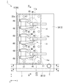
- FIG. 3 is a sectional view taken along line III-III in FIG. 2. It is a principal part enlarged view of FIG.
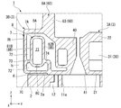
- FIG. 5 is a sectional view taken along line VV of FIG. 2.
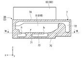
- FIG. 6 is a VI-VI sectional view of FIG. 2.
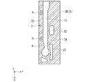
- FIG. 7 is a sectional view taken along line VII-VII in FIG. 6.
- a cylinder head body 3A constitutes an engine 1 together with a cylinder block 2.
- the engine 1 of this embodiment is a diesel engine. 1 to 7, the direction in which the cylinder block 2 and the cylinder head body 3A are arranged is the Z-axis direction (vertical direction). A direction orthogonal to the Z-axis direction is the Y-axis direction (cylinder row direction). Further, the direction orthogonal to the Z-axis direction and the Y-axis direction is the X-axis direction (front-back direction).
- the cylinder block 2 has a cylinder bore 11 a forming a cylinder 11.
- the cylinder 11 is a space in which the piston 4 is arranged.
- the cylinder 11 opens on the upper surface 2 a of the cylinder block 2.
- the piston 4 receives the pressure of the combustion gas burned in the cylinder 11 and reciprocates in the Z-axis direction.
- the cylinder block 2 of the present embodiment has a plurality of (three in the illustrated example) cylinders 11 as shown in FIG.
- the plurality of cylinders 11 are arranged in a line in the Y-axis direction.
- the first orthogonal direction in which the plurality of cylinders 11 are arranged is also referred to as a cylinder row direction.
- a block side circulation space 12 is formed which surrounds each cylinder bore 11a and through which cooling water flows. Cooling water for cooling the cylinder bore 11a flows through the block-side circulation space 12.
- the block side circulation space 12 opens on the upper surface 2 a of the cylinder block 2.
- a camshaft 5 for driving a rocker arm 47 described later is arranged in the cylinder block 2.
- the cam shaft 5 extends in the cylinder row direction.
- the camshaft 5 rotates according to the reciprocating motion of the piston 4.
- the cylinder head 3 is disposed so as to overlap the upper surface 2 a of the cylinder block 2 so as to cover the upper opening of the cylinder 11.
- the cylinder head 3 has a cylinder head body 3A and a bulging portion 3B (FIG. 2).
- the cylinder head body 3A includes a lower deck 21 and an upper deck 22.
- the lower deck 21 and the upper deck 22 are each formed in a plate shape.
- the lower deck 21 is a portion of the cylinder head body 3A, which is arranged so as to overlap with the upper surface 2a of the cylinder block 2.
- the upper deck 22 is provided above the lower deck 21 so as to face the lower deck 21. That is, the lower deck 21 and the upper deck 22 are arranged at intervals in the Z-axis direction.
- the upper deck 22 and the lower deck 21 define a head-side circulation space 30 in which cooling water flows.
- a cooling water introduction hole 23 is formed in the lower deck 21.
- the cooling water introduction hole 23 penetrates the lower deck 21 in the plate thickness direction (Z axis direction) thereof.
- the cooling water introduction hole 23 connects the block side circulation space 12 of the cylinder block 2 and the head side circulation space 30 of the cylinder head body 3A.
- the cylinder head body 3A includes a valve hole forming wall 40 extending from the lower deck 21 to the upper deck 22.
- the valve hole forming wall 40 is formed with an intake valve hole 41 and an exhaust valve hole 42 (dotted line) that open to the lower surface 21b of the lower deck 21.
- the lower surface 21b of the lower deck 21 is a surface facing the upper surface 2a of the cylinder block 2.
- the intake valve hole 41 and the exhaust valve hole 42 are formed at the lower end of the valve hole forming wall 40 located on the lower deck 21 side.
- the intake valve hole 41 and the exhaust valve hole 42 communicate with the cylinder 11 of the cylinder block 2, respectively.
- a fuel injector 44 (injector) is vertically inserted into the valve hole forming wall 40.
- the fuel injector 44 vertically penetrates the cylinder head body 3A. That is, the fuel injector 44 projects from the lower surface 21b of the lower deck 21 and the upper surface 22a of the upper deck 22.
- an intake valve 45 that opens and closes each intake valve hole 41 is provided in the valve hole forming wall 40 so as to be vertically movable. A part of the intake valve 45 projects from the upper surface 22 a of the upper deck 22. Further, the valve hole forming wall 40 is provided with an exhaust valve 46 that opens and closes each exhaust valve hole 42 (FIG. 2) similarly to the intake valve 45.
- the exhaust valve 46 has the same configuration and arrangement as the intake valve 45.
- the intake valve 45 and the exhaust valve 46 are each driven by rocking a rocker arm 47 provided on the upper surface 22a of the upper deck 22. The rocker arm 47 swings as the push rod 48 penetrating the cylinder head body 3A in the vertical direction moves in the vertical direction as the cam shaft 5 rotates.
- valve hole forming walls 40 are arranged in a line at intervals in the Y-axis direction.
- the plurality of valve hole forming walls 40 are located so as to correspond to the plurality of cylinders 11, respectively.
- two intake valve holes 41 and one exhaust valve hole 42 (shown in FIG. 1) correspond to one cylinder 11.
- the cylinder head body 3A includes an intake port forming portion 51 connected to the valve hole forming wall 40.
- the intake port forming portion 51 is located on one side in the Z-axis direction and the X-axis direction (the positive side of the X-axis, the right side in FIG. 1) with respect to the valve hole forming wall 40.
- the intake port forming portion 51 is integrally formed on the lower surface of the upper deck 22 and is arranged above the lower deck 21. A space between the lower deck 21 and the intake port forming portion 51 constitutes a head side circulation space 30.
- An intake port 53 communicating with the intake valve hole 41 is formed in the intake port forming portion 51.
- the intake port 53 extends from the intake valve hole 41 to one side in the X-axis direction. That is, the intake port 53 is formed so as to intake air from the intake side of the cylinder head body 3A, which is one side in the X-axis direction.
- a plurality of intake port forming portions 51 (three in the illustrated example) are arranged at intervals in the Y-axis direction so as to correspond to the plurality of valve hole forming walls 40, respectively.
- Each intake port forming portion 51 is formed with two intake ports 53 communicating with each of the two intake valve holes 41 formed in each valve hole forming wall 40.
- the cylinder head body 3A includes an exhaust port forming portion 52 connected to each valve hole forming wall 40.
- the exhaust port forming portion 52 is located on the other side in the X-axis direction (the negative side of the X-axis, the left side in FIG. 1) with respect to the valve hole forming wall 40.
- the exhaust port forming portion 52 is arranged above the lower deck 21 and below the upper deck 22 with a space between the lower deck 21 and the upper deck 22.
- a space between the lower deck 21 and the exhaust port forming portion 52, and a space between the upper deck 22 and the exhaust port forming portion 52 respectively constitute a head side circulation space 30.
- An exhaust port 54 communicating with the exhaust valve hole 42 is formed in the exhaust port forming portion 52.
- the exhaust port 54 extends from the exhaust valve hole 42 to the other side in the X-axis direction. That is, the exhaust port 54 is formed so as to exhaust to the exhaust side of the cylinder head body 3A, which is the other side in the X-axis direction.
- a plurality of (three) exhaust port forming portions 52 are arranged at intervals in the first orthogonal direction so as to correspond to each of the plurality of valve hole forming walls 40.
- the cylinder head body 3A further includes an outer peripheral wall 60 provided on the outer peripheral side of the plurality of valve hole forming walls 40 described above.
- the outer peripheral wall 60 extends from the lower deck 21 to the upper deck 22 so as to surround the plurality of valve hole forming walls 40, and together with the lower deck 21 and the upper deck 22, defines the head side circulation space 30.
- the outer peripheral wall 60 has two side walls 61 and 62 and one end wall (not shown) on the Y-axis side in FIG. As shown in FIG. 1, the two side walls 61 and 62 extend in the Y-axis direction at both ends of the cylinder head body 3A in the X-axis direction.
- the intake port forming portion 51 described above is integrally formed on the intake side side wall 61 located on the intake side of the two side walls 61 and 62.
- An intake port 53 penetrates the intake side wall 61.
- the exhaust port forming portion 52 is integrally formed on the exhaust side side wall 62 located on the exhaust side of the two side walls 61 and 62.
- the exhaust port 54 penetrates through the exhaust side wall 62.
- the push rod 48 described above penetrates through the exhaust side sidewall 62 in the Z-axis direction. A plurality of push rods 48 are arranged at intervals in the Y-axis direction.
- the head side circulation space 30 is divided into two spaces by a first partition wall 81 and a second partition wall 82.
- the first partition wall 81 partitions the lower part of the head side circulation space 30 located on the lower deck 21 side in the Z-axis direction into an intake side space and an exhaust side space.
- the first partition wall 81 connects the adjacent valve hole forming walls 40, and also connects the valve hole forming wall 40 and the outer peripheral wall 60 located at both ends in the arrangement direction of the plurality of valve hole forming walls 40. Is formed in.
- the second partition wall 82 is a lower part including a space on the exhaust side located on the exhaust side of the valve hole forming wall 40 and the first partition wall 81 in the X-axis direction, and including the lower side of the exhaust port forming part 52 in the Z-axis direction.
- the space is divided into an upper space including the upper side of the exhaust port forming portion 52.
- the head side circulation space 30 is a second cooling space 31 including a space on the intake side and an upper space on the exhaust side, and a second space formed on the exhaust side by the first partition wall 81 and the second partition wall 82. It is partitioned into a cooling water space 32.
- the rocker housing 6 is integrally formed with the cylinder head body 3A of the present embodiment.
- the rocker housing 6 has a rocker side wall 6A.
- the rocker side wall 6A is formed so as to extend above the cylinder head body 3A (Z axis positive direction) at the peripheral edge of the upper surface 22a of the upper deck 22 (cylinder head body 3A), and is provided on the upper surface 22a of the upper deck 22.
- an intake manifold 3C is integrally formed with the cylinder head body 3A of the present embodiment.
- the intake manifold 3C is connected to the intake side wall 61 of the cylinder head body 3A.
- the intake manifold 3C extends in the first orthogonal direction so that its internal space communicates with each of the plurality of intake ports 53 arranged in the Y-axis direction.
- a bulge portion 3B is integrally provided on one side in the Y-axis direction of the cylinder head body 3A. That is, the bulging portion 3B bulges from the cylinder head body 3A toward one side in the cylinder row direction. As shown in FIGS. 3 and 4, the bulging portion 3B extends in the vertical direction across the lower deck 21 and the rocker side wall 6A.
- the bulging portion 3B has a bulging wall portion 7.
- the bulging wall portion 7 is composed of an upper wall 7A, a side wall 7B, and a lower wall 7C.
- the upper wall 7A projects from the rocker side wall 6A toward one side in the cylinder column direction.
- the upper wall 7A is located above the upper deck 22 in the vertical direction. That is, in the present embodiment, the upper surface of the upper wall 7A is located above the upper surface of the upper deck 22, and the lower surface of the upper wall 7A is located above the lower surface of the upper deck 22.
- the side wall 7B extends downward from an edge of the upper wall 7A on one side in the cylinder row direction.
- the lower wall 7C connects the lower edge of the side wall 7B to the lower deck 21.
- a gap g is formed between the lower surface of the lower wall 7C and the upper surface 2a of the cylinder block 2. The formation of this gap g suppresses the transfer of heat from the cylinder block 2 to the bulging wall portion 7.
- a second cooling water space 72 through which cooling water flows is formed inside the bulging wall portion 7.
- the second cooling water space 72 communicates with one side of the first cooling water space 31 in the cylinder row direction. That is, a part of the cooling water supplied through the partitioned space 31 flows in the second cooling water space 72.
- the second cooling water space 72 extends to a position above the upper deck 22. .. As shown in FIG. 5, the cooling water that has flowed through the second cooling space 72 is discharged through the discharge portion E formed on the upper portion of the bulging wall portion 7.
- the EGR passage forming portion 8 is provided inside the second cooling water space 72.
- the EGR passage forming portion 8 has a tubular shape extending in the X-axis direction within the second cooling water space 72.
- the EGR passage formation portion 8 has an upper wall 8A, a pair of side walls 8B and 8B, and a lower wall 8C.
- the upper wall 8A and the lower wall 8C face each other in the Z-axis direction.
- the pair of side walls 8B and 8B connect the upper wall 8A and the lower wall 8C in the Z-axis direction.
- the upper wall 8A is located further above the upper deck 22 described above.
- the periphery of the EGR passage forming part 8 is filled with cooling water. More specifically, the upper wall 8A, the pair of side walls 8B and 8B, and the lower wall 8C are all exposed to the cooling water.
- An EGR passage 71 through which EGR gas flows is formed inside the EGR passage forming portion 8. One end of the EGR passage 71 communicates with an exhaust manifold (not shown) attached to the cylinder head body 3A. The other end of the EGR passage 71 communicates with the intake manifold 3C described above. A part of the exhaust gas guided from the exhaust manifold is sent to the intake manifold after flowing through the EGR passage 71.
- the EGR passage 71 has an introduction portion 71A, an enlarged portion 71B, a main body portion 71C, and a curved portion 71D that are sequentially connected from one end side (the introduction port P1 side) to the other end side (the discharge port P2 side). It is composed by.
- One end of the introduction portion 71A is an introduction port P1.
- the inlet P1 is connected to the exhaust manifold.
- the flow passage cross-sectional area gradually increases from the introduction portion 71A side toward the main body portion 71C side.
- the vertical dimension gradually increases toward the main body portion 71C.
- the flow passage cross-sectional area is constant over the entire extension length thereof.
- the curved portion 71D is gradually curved downward from the downstream end of the main body portion 71C toward the discharge port P2. That is, the outlet P2 opens downward.
- first connection part, second connection part As shown in FIGS. 4 and 6, of the pair of side walls 8B and 8B in the EGR passage forming portion 8, one side wall 8B (first side wall 81B on one side in the cylinder row direction) is the side wall 7B of the bulging wall portion 7. On the other hand, they are connected in the cylinder column direction by the first connecting portion 73.
- the first connecting portion 73 has a plate shape that extends in the cylinder row direction and the front-rear direction.
- the first connection portion 73 is formed with a plurality of (two in the illustrated example) communication holes h penetrating the first connection portion 73 in the vertical direction. As shown in FIG. 7, the communication hole h is an elongated hole (slit) having a longitudinal direction in the front-rear direction. Through these communication holes h, the upper space and the lower space are in communication with each other with the first connecting portion 73 interposed therebetween.
- the other side wall 8B (the first side wall 82B on the other side in the Y-axis direction) is formed with respect to the cylinder head body 3A.
- the second connecting portions 74 are connected in the cylinder column direction.
- the second connecting portion 74 has a plate shape that extends in the cylinder row direction and the front-rear direction.
- part of the exhaust gas sent to the exhaust manifold is guided to the intake manifold 3C via the EGR passage 71 and is recirculated to the cylinder head 3. Since the periphery of the EGR passage 71 is covered with the second cooling water space 72 (cooling water), the exhaust gas flowing through the EGR passage 71 is gradually cooled in the middle of flowing, and becomes a relatively low temperature. Is sent to the intake manifold 3C.
- the bulging portion 3B is formed to bulge over the lower deck 21 and the rocker side wall 6A.
- the second cooling water space 72 expands above the upper deck 22. That is, it is possible to secure a large second cooling water space 72 especially in the vertical direction.
- the EGR passage 71 EGR passage forming portion 8
- the cooling efficiency of the exhaust gas flowing through the EGR passage 71 is further improved.
- the rocker side wall 6A and the upper deck 22 are integrally formed, it is not necessary to form a bolt hole for attaching the rocker side wall 6A to the upper deck 22 as in the conventional case.
- the bolt holes are formed, the volume of the second cooling water space 72 is restricted by the area occupied by the bolt holes.
- such a restriction can be avoided and a large volume of the second cooling water space 72 can be secured.
- the EGR passage forming portion 8 has the upper end (upper wall 8A) extending in the front-rear direction located above the upper deck 22.
- a large surface area of the EGR passage forming portion 8 that is, a contact area with the second cooling water space 72
- the cooling efficiency of the EGR gas can be further improved.
- the first connecting portion 73 that connects the EGR passage forming portion 8 to the bulging portion 3B and the other in the cylinder row direction.
- a second connecting portion 74 that connects the EGR passage forming portion 8 to the cylinder head body 3A is provided.
- the EGR passage forming portion 8 By connecting the EGR passage forming portion 8 to the cylinder head body 3A and the bulging portion 3B by the first connecting portion 73 and the second connecting portion 74, the above-mentioned force is exerted on the EGR passage forming portion 8 as well. become.
- the gas passage forming portion 8 itself can be used as a part of the strength member to bear the strength. Thereby, the durability of the cylinder head 3 can be further improved.
- the first connecting portion 73 is formed with a communication hole h that vertically penetrates the first connecting portion 73.
- the cooling water passes through the communication holes h, it is possible to reduce the possibility of the cooling water stagnation and retention in the second cooling water space 72. As a result, it becomes possible to efficiently cool the entire EGR passage forming portion 8 from the surroundings.
- the number of cylinders in the engine of the present invention may be one, for example. That is, the number of valve hole forming walls in the cylinder head of the present invention may be one, for example.
- the engine of the present invention may be applied to any work vehicle such as a dump truck, a hydraulic excavator, a wheel loader, a bulldozer, and an engine forklift.
Landscapes
- Engineering & Computer Science (AREA)
- Chemical & Material Sciences (AREA)
- Combustion & Propulsion (AREA)
- Mechanical Engineering (AREA)
- General Engineering & Computer Science (AREA)
- Cylinder Crankcases Of Internal Combustion Engines (AREA)
Abstract
シリンダヘッド(3)は、ロアデッキ(21)、ロアデッキ(21)とともに第一冷却水空間(31)を画成するアッパーデッキ(22)、バルブ孔形成壁(40)を有するシリンダヘッド本体(3A)と、シリンダヘッド本体(3A)と一体形成されたロッカ側壁(6A)を有するロッカハウジング(6)と、シリンダヘッド本体(3A)から膨出し、第一冷却水空間(31)に連通するとともにアッパーデッキ(22)よりも上方側に広がる第二冷却水空間(72)を画成する膨出壁部(3B)と、第二冷却水空間(72)内に設けられたEGR通路形成部(8)と、を備える。
Description
本発明は、シリンダヘッド及びエンジンに関する。
エンジンの燃焼過程で発生する排気ガスに含まれるサーマルNOxの低減や、部分負荷時の燃費向上を目的として、排気再循環(Exhaust Gas Recirculation:EGR)と呼ばれる技術が広く用いられている。特に外部EGRと呼ばれる形式のEGR装置では、エンジンのシリンダから排気マニホールドに送出される排気ガスの一部を、EGR通路を介して吸気マニホールドに導き、シリンダボア内に還流させる。
このようなEGR装置を備えるエンジンの一例として、下記特許文献1に記載されたものが知られている。特許文献1に係るエンジンでは、エンジンのシリンダヘッドの内部に、排気ガス(EGRガス)が通るEGR通路が設けられている。さらに、このEGR通路の一方側には、ウォータージャケットが設けられている。ウォータージャケットを流通する冷却水との熱交換によって、EGR通路内の排気ガス(EGRガス)が冷却される。冷却された排気ガスは吸気マニホールドに導かれる。
ところで、EGRガスの冷却効率を上げるために、EGR通路の流路断面積や容積を大きくしたいという要請がある。しかしながら、従来シリンダヘッドはシリンダブロックと別体に形成されることが一般的であった。したがって、シリンダヘッドには、当該シリンダヘッドをシリンダブロックに固定するためのボルトを挿通させる取付孔が形成される。このため、シリンダヘッド内部にEGR通路を設けるに当たって、寸法上の制約が生じる虞がある。その結果、EGRガスの冷却効率を十分に向上させられなくなってしまう。
本発明はこのような課題に鑑みてなされたものであって、EGRガスをより一層効率的に冷却することが可能なシリンダヘッド及びエンジンを提供することを目的とする。
本発明の第一の態様に係るシリンダヘッドは、ロアデッキ、該ロアデッキの上方で前記ロアデッキと対向するように設けられて該ロアデッキとともに第一冷却水空間を画成するアッパーデッキ、前記ロアデッキと前記アッパーデッキとにわたって延びて気筒列方向に複数が形成されたバルブ孔形成壁を有するシリンダヘッド本体と、前記アッパーデッキにおける前記気筒列方向一方側の端部から立ち上がるように、前記シリンダヘッド本体と一体形成されたロッカ側壁を有するロッカハウジングと、前記シリンダヘッド本体から前記気筒列方向一方側に膨出するように前記ロアデッキ及びロッカ側壁にわたって設けられて、前記第一冷却水空間の前記気筒列方向一方側に連通するとともに前記アッパーデッキよりも上方側に広がる第二冷却水空間を画成する膨出壁部と、前記第二冷却水空間内で前記気筒列方向に交差する前後方向に延びるように設けられたEGR通路形成部と、を備える。
本発明の第一の態様に係るエンジンは、上述の態様に係るシリンダヘッドと、気筒を形成するシリンダボアを有し、前記シリンダヘッドによって上方から覆われるシリンダブロックと、を備える。
本発明によれば、EGRガスをより一層効率的に冷却することが可能なシリンダヘッド及びエンジンを提供することができる。
以下、本発明の一実施形態について、図1から図7を参照して説明する。図1に示すように、本実施形態に係るシリンダヘッド本体3Aは、シリンダブロック2とともにエンジン1を構成する。本実施形態のエンジン1は、ディーゼルエンジンである。
図1から図7では、シリンダブロック2とシリンダヘッド本体3Aとが配列される方向をZ軸方向(上下方向)とする。また、Z軸方向に直交する方向をY軸方向(気筒列方向)をとする。さらに、Z軸方向及びY軸方向に直交する方向をX軸方向(前後方向)とする。
図1から図7では、シリンダブロック2とシリンダヘッド本体3Aとが配列される方向をZ軸方向(上下方向)とする。また、Z軸方向に直交する方向をY軸方向(気筒列方向)をとする。さらに、Z軸方向及びY軸方向に直交する方向をX軸方向(前後方向)とする。
<シリンダブロック>
図1に示すように、シリンダブロック2は、気筒11を形成するシリンダボア11aを有する。気筒11は、ピストン4が配される空間である。気筒11は、シリンダブロック2の上面2aに開口する。ピストン4は、気筒11内において燃焼した燃焼ガスの圧力を受けてZ軸方向に往復運動する。本実施形態のシリンダブロック2は、図2に示すように複数(図示例では3つ)の気筒11を有する。複数の気筒11は、Y軸方向に一列に並んでいる。以下の説明では、複数の気筒11が配列される第一直交方向を気筒列方向とも呼ぶ。
図1に示すように、シリンダブロック2は、気筒11を形成するシリンダボア11aを有する。気筒11は、ピストン4が配される空間である。気筒11は、シリンダブロック2の上面2aに開口する。ピストン4は、気筒11内において燃焼した燃焼ガスの圧力を受けてZ軸方向に往復運動する。本実施形態のシリンダブロック2は、図2に示すように複数(図示例では3つ)の気筒11を有する。複数の気筒11は、Y軸方向に一列に並んでいる。以下の説明では、複数の気筒11が配列される第一直交方向を気筒列方向とも呼ぶ。
図1に示すように、シリンダブロック2内には、各シリンダボア11aを囲むとともに冷却水が流通するブロック側流通空間12が形成されている。ブロック側流通空間12には、シリンダボア11aを冷却する冷却水が流通する。ブロック側流通空間12は、シリンダブロック2の上面2aに開口する。
図1に示すように、シリンダブロック2内には、後述するロッカアーム47を駆動するためのカムシャフト5が配される。カムシャフト5は、気筒列方向に延びている。カムシャフト5は、ピストン4の往復運動に応じて回転する。
<シリンダヘッド>
図1に示すように、シリンダヘッド3は、気筒11の上方の開口を覆うように、シリンダブロック2の上面2aに重ねて配される。シリンダヘッド3は、シリンダヘッド本体3Aと、膨出部3B(図2)と、を有している。
図1に示すように、シリンダヘッド3は、気筒11の上方の開口を覆うように、シリンダブロック2の上面2aに重ねて配される。シリンダヘッド3は、シリンダヘッド本体3Aと、膨出部3B(図2)と、を有している。
<シリンダヘッド本体>
図1に示すように、シリンダヘッド本体3Aは、ロアデッキ21及びアッパーデッキ22を備える。ロアデッキ21及びアッパーデッキ22は、それぞれ板状に形成されている。ロアデッキ21は、シリンダヘッド本体3Aのうちシリンダブロック2の上面2aに重ねて配される部位である。アッパーデッキ22は、ロアデッキ21の上方でロアデッキ21に対向するように設けられる。すなわち、ロアデッキ21及びアッパーデッキ22は、Z軸方向に間隔をあけて配列されている。アッパーデッキ22は、ロアデッキ21との間に冷却水が流通するヘッド側流通空間30を画成する。
図1に示すように、シリンダヘッド本体3Aは、ロアデッキ21及びアッパーデッキ22を備える。ロアデッキ21及びアッパーデッキ22は、それぞれ板状に形成されている。ロアデッキ21は、シリンダヘッド本体3Aのうちシリンダブロック2の上面2aに重ねて配される部位である。アッパーデッキ22は、ロアデッキ21の上方でロアデッキ21に対向するように設けられる。すなわち、ロアデッキ21及びアッパーデッキ22は、Z軸方向に間隔をあけて配列されている。アッパーデッキ22は、ロアデッキ21との間に冷却水が流通するヘッド側流通空間30を画成する。
ロアデッキ21には、冷却水導入孔23が形成されている。冷却水導入孔23は、ロアデッキ21をその板厚方向(Z軸方向)に貫通する。冷却水導入孔23は、シリンダブロック2のブロック側流通空間12と、シリンダヘッド本体3Aのヘッド側流通空間30とをつなぐ。
<バルブ孔形成壁>
図1に示すように、シリンダヘッド本体3Aは、ロアデッキ21からアッパーデッキ22まで延びるバルブ孔形成壁40を備える。バルブ孔形成壁40には、ロアデッキ21の下面21bに開口する吸気バルブ孔41及び排気バルブ孔42(点線)が形成されている。ロアデッキ21の下面21bは、シリンダブロック2の上面2aに対向する面である。吸気バルブ孔41及び排気バルブ孔42は、ロアデッキ21側に位置するバルブ孔形成壁40の下端部に形成される。吸気バルブ孔41及び排気バルブ孔42は、それぞれシリンダブロック2の気筒11に連通する。
図1に示すように、シリンダヘッド本体3Aは、ロアデッキ21からアッパーデッキ22まで延びるバルブ孔形成壁40を備える。バルブ孔形成壁40には、ロアデッキ21の下面21bに開口する吸気バルブ孔41及び排気バルブ孔42(点線)が形成されている。ロアデッキ21の下面21bは、シリンダブロック2の上面2aに対向する面である。吸気バルブ孔41及び排気バルブ孔42は、ロアデッキ21側に位置するバルブ孔形成壁40の下端部に形成される。吸気バルブ孔41及び排気バルブ孔42は、それぞれシリンダブロック2の気筒11に連通する。
図1に示すように、バルブ孔形成壁40には、燃料噴射器44(インジェクタ)が上下方向に挿入されている。燃料噴射器44は、シリンダヘッド本体3Aを上下方向に貫通する。すなわち、燃料噴射器44は、ロアデッキ21の下面21b及びアッパーデッキ22の上面22aから突出する。
図1,2に示すように、バルブ孔形成壁40には、各吸気バルブ孔41を開閉する吸気バルブ45が上下方向に移動可能に設けられている。吸気バルブ45の一部は、アッパーデッキ22の上面22aから突出する。また、バルブ孔形成壁40には、吸気バルブ45と同様に、各排気バルブ孔42(図2)を開閉する排気バルブ46が設けられている。排気バルブ46の構成や配置は、吸気バルブ45と同様である。
吸気バルブ45及び排気バルブ46は、それぞれアッパーデッキ22の上面22aに設けられたロッカアーム47を揺動させることで駆動される。ロッカアーム47は、前述したカムシャフト5の回転に伴ってシリンダヘッド本体3Aの上下方向に貫通するプッシュロッド48が上下方向に移動することで揺動する。
吸気バルブ45及び排気バルブ46は、それぞれアッパーデッキ22の上面22aに設けられたロッカアーム47を揺動させることで駆動される。ロッカアーム47は、前述したカムシャフト5の回転に伴ってシリンダヘッド本体3Aの上下方向に貫通するプッシュロッド48が上下方向に移動することで揺動する。
本実施形態においては、図3に示すように、複数(図示例では3つ)のバルブ孔形成壁40が、Y軸方向に互いに間隔をあけて一列に配列されている。複数のバルブ孔形成壁40は、複数の気筒11のそれぞれに対応するように位置する。本実施形態においては、2つの吸気バルブ孔41及び1つの排気バルブ孔42(図1に図示)が、1つの気筒11に対応している。
<吸気ポート形成部>
図1に示すように、シリンダヘッド本体3Aは、バルブ孔形成壁40に接続される吸気ポート形成部51を備える。吸気ポート形成部51は、バルブ孔形成壁40に対して、Z軸方向及びX軸方向一方側(X軸の正方向側、図1の右側)に位置する。吸気ポート形成部51は、アッパーデッキ22の下面に一体に形成され、ロアデッキ21の上方に配置される。ロアデッキ21と吸気ポート形成部51との間の空間は、ヘッド側流通空間30を構成している。
図1に示すように、シリンダヘッド本体3Aは、バルブ孔形成壁40に接続される吸気ポート形成部51を備える。吸気ポート形成部51は、バルブ孔形成壁40に対して、Z軸方向及びX軸方向一方側(X軸の正方向側、図1の右側)に位置する。吸気ポート形成部51は、アッパーデッキ22の下面に一体に形成され、ロアデッキ21の上方に配置される。ロアデッキ21と吸気ポート形成部51との間の空間は、ヘッド側流通空間30を構成している。
吸気ポート形成部51には、吸気バルブ孔41に連通する吸気ポート53が形成されている。吸気ポート53は、吸気バルブ孔41からX軸方向一方側に延びる。すなわち、吸気ポート53は、X軸方向一方側であるシリンダヘッド本体3Aの吸気側から吸気するように形成されている。
吸気ポート形成部51は、複数のバルブ孔形成壁40のそれぞれに対応するように、Y軸方向に互いに間隔をあけて複数(図示例では3つ)配列されている。各吸気ポート形成部51には、各バルブ孔形成壁40に形成された2つの吸気バルブ孔41のそれぞれに連通する2つの吸気ポート53が形成されている。
吸気ポート形成部51は、複数のバルブ孔形成壁40のそれぞれに対応するように、Y軸方向に互いに間隔をあけて複数(図示例では3つ)配列されている。各吸気ポート形成部51には、各バルブ孔形成壁40に形成された2つの吸気バルブ孔41のそれぞれに連通する2つの吸気ポート53が形成されている。
<排気ポート形成部>
図1に示すように、シリンダヘッド本体3Aは、各バルブ孔形成壁40に接続される排気ポート形成部52を備える。排気ポート形成部52は、バルブ孔形成壁40に対して、X軸方向他方側(X軸の負方向側、図1の左側)に位置する。排気ポート形成部52は、ロアデッキ21の上方かつアッパーデッキ22の下方で、これらロアデッキ21及びアッパーデッキ22と間隔をあけて配置される。ロアデッキ21と排気ポート形成部52との間の空間、及び、アッパーデッキ22と排気ポート形成部52との間の空間は、それぞれヘッド側流通空間30を構成している。
図1に示すように、シリンダヘッド本体3Aは、各バルブ孔形成壁40に接続される排気ポート形成部52を備える。排気ポート形成部52は、バルブ孔形成壁40に対して、X軸方向他方側(X軸の負方向側、図1の左側)に位置する。排気ポート形成部52は、ロアデッキ21の上方かつアッパーデッキ22の下方で、これらロアデッキ21及びアッパーデッキ22と間隔をあけて配置される。ロアデッキ21と排気ポート形成部52との間の空間、及び、アッパーデッキ22と排気ポート形成部52との間の空間は、それぞれヘッド側流通空間30を構成している。
排気ポート形成部52には、排気バルブ孔42に連通する排気ポート54が形成されている。排気ポート54は、排気バルブ孔42からX軸方向他方側に延びる。すなわち、排気ポート54は、X軸方向他方側であるシリンダヘッド本体3Aの排気側に排気するように形成されている。
排気ポート形成部52は、複数のバルブ孔形成壁40のそれぞれに対応するように、第一直交方向に互いに間隔をあけて複数(3つ)配列されている。
排気ポート形成部52は、複数のバルブ孔形成壁40のそれぞれに対応するように、第一直交方向に互いに間隔をあけて複数(3つ)配列されている。
<外周壁>
図1に示すように、シリンダヘッド本体3Aは、前述した複数のバルブ孔形成壁40の外周側に設けられた外周壁60をさらに備える。外周壁60は、複数のバルブ孔形成壁40を囲むようにロアデッキ21からアッパーデッキ22まで延び、ロアデッキ21及びアッパーデッキ22とともにヘッド側流通空間30を画成する。
図1に示すように、シリンダヘッド本体3Aは、前述した複数のバルブ孔形成壁40の外周側に設けられた外周壁60をさらに備える。外周壁60は、複数のバルブ孔形成壁40を囲むようにロアデッキ21からアッパーデッキ22まで延び、ロアデッキ21及びアッパーデッキ22とともにヘッド側流通空間30を画成する。
外周壁60には、2つの側壁61,62と、図2のY軸側の1つの端壁(図示省略)とがある。図1に示すように、2つの側壁61,62は、X軸方向におけるシリンダヘッド本体3Aの両端においてY軸方向に延びる。2つの側壁61,62のうち吸気側に位置する吸気側側壁61には、前述した吸気ポート形成部51が一体に形成される。吸気側側壁61には、吸気ポート53が貫通する。2つの側壁61,62のうち排気側に位置する排気側側壁62には、前述した排気ポート形成部52が一体に形成される。排気側側壁62には、排気ポート54が貫通する。また、排気側側壁62には、前述したプッシュロッド48がZ軸方向に貫通する。プッシュロッド48は、Y軸方向に互いに間隔をあけて複数配列されている。
<ヘッド側流通空間>
図1に示すように、本実施形態のシリンダヘッド本体3Aにおいて、ヘッド側流通空間30は、第一区画壁81及び第二区画壁82によって2つの空間に区画されている。
第一区画壁81は、Z軸方向においてロアデッキ21側に位置するヘッド側流通空間30の下側部分を、吸気側の空間と排気側の空間とに区画する。第一区画壁81は、隣り合うバルブ孔形成壁40同士をつなぐように、また、複数のバルブ孔形成壁40の配列方向の両端に位置するバルブ孔形成壁40と外周壁60とをつなぐように形成されている。
図1に示すように、本実施形態のシリンダヘッド本体3Aにおいて、ヘッド側流通空間30は、第一区画壁81及び第二区画壁82によって2つの空間に区画されている。
第一区画壁81は、Z軸方向においてロアデッキ21側に位置するヘッド側流通空間30の下側部分を、吸気側の空間と排気側の空間とに区画する。第一区画壁81は、隣り合うバルブ孔形成壁40同士をつなぐように、また、複数のバルブ孔形成壁40の配列方向の両端に位置するバルブ孔形成壁40と外周壁60とをつなぐように形成されている。
第二区画壁82は、X軸方向においてバルブ孔形成壁40及び第一区画壁81よりも排気側に位置する排気側の空間を、Z軸方向において排気ポート形成部52の下側を含む下部空間と排気ポート形成部52の上側を含む上部空間とに区画する。
ヘッド側流通空間30は、これら第一区画壁81及び第二区画壁82によって、吸気側の空間及び排気側の上部空間を含む第一冷却水空間31と、排気側の下部空間からなる第二冷却水空間32とに区画される。
ヘッド側流通空間30は、これら第一区画壁81及び第二区画壁82によって、吸気側の空間及び排気側の上部空間を含む第一冷却水空間31と、排気側の下部空間からなる第二冷却水空間32とに区画される。
<ロッカハウジング>
図1,2に示すように、本実施形態のシリンダヘッド本体3Aには、ロッカハウジング6が一体に成形されている。ロッカハウジング6は、ロッカ側壁6Aと、を有する。ロッカ側壁6Aは、アッパーデッキ22(シリンダヘッド本体3A)の上面22aの周縁においてシリンダヘッド本体3Aの上方(Z軸正方向)に延びて形成され、アッパーデッキ22の上面22aに設けられたロッカアーム47などを囲む。
また、本実施形態のシリンダヘッド本体3Aには、吸気マニホールド3Cが一体に成形されている。吸気マニホールド3Cは、シリンダヘッド本体3Aの吸気側側壁61に接続される。吸気マニホールド3Cは、その内部空間がY軸方向に配列された複数の吸気ポート53のそれぞれに連通するように、第一直交方向に延びている。
図1,2に示すように、本実施形態のシリンダヘッド本体3Aには、ロッカハウジング6が一体に成形されている。ロッカハウジング6は、ロッカ側壁6Aと、を有する。ロッカ側壁6Aは、アッパーデッキ22(シリンダヘッド本体3A)の上面22aの周縁においてシリンダヘッド本体3Aの上方(Z軸正方向)に延びて形成され、アッパーデッキ22の上面22aに設けられたロッカアーム47などを囲む。
また、本実施形態のシリンダヘッド本体3Aには、吸気マニホールド3Cが一体に成形されている。吸気マニホールド3Cは、シリンダヘッド本体3Aの吸気側側壁61に接続される。吸気マニホールド3Cは、その内部空間がY軸方向に配列された複数の吸気ポート53のそれぞれに連通するように、第一直交方向に延びている。
<膨出部>
図1~4に示すように、シリンダヘッド本体3AのY軸方向一方側には、膨出部3Bが一体に設けられている。つまり、膨出部3Bは、シリンダヘッド本体3Aから気筒列方向一方側に向かって膨出している。図3,4に示すように、膨出部3Bは、上下方向において、ロアデッキ21とロッカ側壁6Aにわたって延びている。
図1~4に示すように、シリンダヘッド本体3AのY軸方向一方側には、膨出部3Bが一体に設けられている。つまり、膨出部3Bは、シリンダヘッド本体3Aから気筒列方向一方側に向かって膨出している。図3,4に示すように、膨出部3Bは、上下方向において、ロアデッキ21とロッカ側壁6Aにわたって延びている。
図4に示すように、膨出部3Bは、膨出壁部7を有する。膨出壁部7は、上壁7Aと、側壁7Bと、下壁7Cと、によって構成されている。上壁7Aは、ロッカ側壁6Aから気筒列方向一方側に向かって突出している。上壁7Aは、上下方向において、上述のアッパーデッキ22よりもさらに上方に位置している。即ち、本実施形態では上壁7Aの上面がアッパーデッキ22の上面よりも上方に位置しており、さらに上壁7Aの下面がアッパーデッキ22の下面よりも上方に位置している。側壁7Bは、上壁7Aの気筒列方向一方側の端縁から下方に向かって延びている。下壁7Cは、側壁7Bの下側の端縁とロアデッキ21とを接続している。下壁7Cの下面とシリンダブロック2の上面2aとの間には隙間gが形成されている。この隙間gが形成されていることによって、シリンダブロック2から膨出壁部7への熱の移動が抑制される。
膨出壁部7の内部には、冷却水が流通する第二冷却水空間72が形成されている。この第二冷却水空間72は、上述の第一冷却水空間31の気筒列方向一方側に連通している。つまり、区画空間31を通じて供給された冷却水の一部が、第二冷却水空間72内を流れる。上述のように、膨出壁部7の上壁7Aがアッパーデッキ22よりも上方に位置していることから、第二冷却水空間72は、当該アッパーデッキ22よりも上方の位置まで広がっている。なお、図5に示すように、第二冷却空間72を流通した冷却水は、膨出壁部7の上部に形成された排出部Eを通じて排出される。
<EGR通路形成部>
図3,4に示すように、第二冷却水空間72の内部には、EGR通路形成部8が設けられている。EGR通路形成部8は、第二冷却水空間72内で、X軸方向に延びる筒状をなしている。図4に示すように、EGR通路形成部8は、上壁8Aと、一対の側壁8B,8Bと、下壁8Cと、を有している。上壁8Aと下壁8Cとは、Z軸方向に対向している。一対の側壁8B,8Bは、これら上壁8Aと下壁8CとをZ軸方向に接続している。なお、上壁8Aは、上述のアッパーデッキ22よりもさらに上方に位置している。
図3,4に示すように、第二冷却水空間72の内部には、EGR通路形成部8が設けられている。EGR通路形成部8は、第二冷却水空間72内で、X軸方向に延びる筒状をなしている。図4に示すように、EGR通路形成部8は、上壁8Aと、一対の側壁8B,8Bと、下壁8Cと、を有している。上壁8Aと下壁8Cとは、Z軸方向に対向している。一対の側壁8B,8Bは、これら上壁8Aと下壁8CとをZ軸方向に接続している。なお、上壁8Aは、上述のアッパーデッキ22よりもさらに上方に位置している。
EGR通路形成部8の周囲は、冷却水で満たされている。より具体的には、上壁8A,一対の側壁8B,8B,及び下壁8Cはいずれも冷却水中に露呈している。EGR通路形成部8の内部には、EGRガスが流通するEGR通路71が形成されている。EGR通路71の一端は、シリンダヘッド本体3Aに取り付けられた排気マニホールド(図示省略)に連通している。EGR通路71の他端は、上述の吸気マニホールド3Cに連通している。排気マニホールドから導かれた排気ガスの一部は、EGR通路71を流通した後、吸気マニホールドに送られる。
図5に示すように、EGR通路71は、一端側(導入口P1側)から他端側(排出口P2側)に向かって順に連なる導入部71A,拡大部71B,本体部71C,湾曲部71Dによって構成されている。導入部71Aの一端は、導入口P1とされている。導入口P1は、排気マニホールドに接続される。拡大部71Bでは、導入部71A側から本体部71C側に向かうに従って、流路断面積が次第に拡大している。具体的には、拡大部71Bでは、上下方向の寸法が本体部71C側に向かうに従って次第に拡大している。本体部71Cでは、流路断面積はその延在長さの全域にわたって一定である。湾曲部71Dは、本体部71Cの下流側の端部から排出口P2に向かうに従って下方に向かって次第に湾曲している。つまり、排出口P2は下方に向かって開口している。
<第一接続部,第二接続部>
図4,6に示すように、EGR通路形成部8における一対の側壁8B,8Bのうち、一方の側壁8B(気筒列方向一方側の第一側壁81B)は、膨出壁部7の側壁7Bに対して、第一接続部73によって気筒列方向に接続されている。第一接続部73は、気筒列方向及び前後方向に広がる板状をなしている。図4,6,7に示すように、第一接続部73には、当該第一接続部73を上下方向に貫通する複数(図示例では2つ)の連通孔hが形成されている。連通孔hは、図7に示すように、前後方向を長手方向とする長穴(スリット)である。これら連通孔hを通じて、第一接続部73を挟んで上側の空間と下側の空間とが互いに連通されている。
図4,6に示すように、EGR通路形成部8における一対の側壁8B,8Bのうち、一方の側壁8B(気筒列方向一方側の第一側壁81B)は、膨出壁部7の側壁7Bに対して、第一接続部73によって気筒列方向に接続されている。第一接続部73は、気筒列方向及び前後方向に広がる板状をなしている。図4,6,7に示すように、第一接続部73には、当該第一接続部73を上下方向に貫通する複数(図示例では2つ)の連通孔hが形成されている。連通孔hは、図7に示すように、前後方向を長手方向とする長穴(スリット)である。これら連通孔hを通じて、第一接続部73を挟んで上側の空間と下側の空間とが互いに連通されている。
さらに、図4に示すように、EGR通路形成部8における一対の側壁8B,8Bのうち、他方の側壁8B(Y軸方向他方側の第一側壁82B)は、シリンダヘッド本体3Aに対して、第二接続部74によって気筒列方向に接続されている。第二接続部74は、気筒列方向及び前後方向に広がる板状をなしている。
<作用効果>
本実施形態に係るシリンダヘッド3では、排気マニホールドに送出される排気ガスの一部を、EGR通路71を介して吸気マニホールド3Cに導き、シリンダヘッド3に還流させる。EGR通路71は、その周囲を第二冷却水空間72(冷却水)で覆われているため、当該EGR通路71を流通する排気ガスは、流通する中途で次第に冷却され、比較的に低温となった状態で吸気マニホールド3Cに送られる。
本実施形態に係るシリンダヘッド3では、排気マニホールドに送出される排気ガスの一部を、EGR通路71を介して吸気マニホールド3Cに導き、シリンダヘッド3に還流させる。EGR通路71は、その周囲を第二冷却水空間72(冷却水)で覆われているため、当該EGR通路71を流通する排気ガスは、流通する中途で次第に冷却され、比較的に低温となった状態で吸気マニホールド3Cに送られる。
ここで、本実施形態では、膨出部3Bがロアデッキ21及びロッカ側壁6Aにわたって膨出するように形成されている。これにより、第二冷却水空間72は、アッパーデッキ22よりも上方側に広がっている。つまり、第二冷却水空間72を特に上下方向に大きく確保することができる。そして、このような容積の大きい第二冷却水空間72内にEGR通路71(EGR通路形成部8)を配置することで、当該EGR通路71を流通する排気ガスの冷却効率をより一層向上させることができる。
また、ロッカ側壁6Aとアッパーデッキ22とは一体形成とされているため、従来のようにロッカ側壁6Aをアッパーデッキ22に取り付けるためのボルト孔を形成する必要がない。ボルト孔を形成した場合、当該ボルト孔の占有する面積によって、第二冷却水空間72の容積が制約を受けてしまう。しかしながら、本実施形態では、このような制約を回避して、第二冷却水空間72の容積を大きく確保することができる。
さらに、本実施形態に係るシリンダヘッド3では、EGR通路形成部8は、前後方向に延びる上端(上壁8A)がアッパーデッキ22よりも上方に位置している。これにより、EGR通路形成部8の表面積(つまり、第二冷却水空間72との接触面積)を大きく確保することができるため、EGRガスの冷却効率をさらに向上させることができる。
また、本実施形態に係るシリンダヘッド3では、EGR通路形成部8の気筒列方向一方側で、当該EGR通路形成部8を膨出部3Bに接続する第一接続部73と、気筒列方向他方側で、当該EGR通路形成部8をシリンダヘッド本体3Aに接続する第二接続部74と、が設けられている。ここで、シリンダヘッド3では、シリンダボア11a内で発生する燃焼ガスによって、シリンダヘッド本体3Aには上方に向かって力が加わる。第一接続部73、及び第二接続部74によって、EGR通路形成部8をシリンダヘッド本体3A、及び膨出部3Bと接続することで、このEGR通路形成部8にも上記の力が及ぶことになる。言い換えれば、ガス通路形成部8自体を強度部材の一部として用い、強度を負担させることができる。これにより、シリンダヘッド3の耐久性をさらに向上させることができる。
加えて、第一接続部73には、当該第一接続部73を上下方向に貫通する連通孔hが形成されている。この連通孔hに冷却水が通過することで、第二冷却水空間72内で冷却水の淀みや滞留が発生する可能性を低減することができる。その結果、EGR通路形成部8全体を周囲から効率よく冷却することが可能となる。
<その他の実施形態>
以上、本発明の実施の形態について説明したが、本発明はこれに限定されることなく、その発明の技術的思想を逸脱しない範囲で適宜変更可能である。
以上、本発明の実施の形態について説明したが、本発明はこれに限定されることなく、その発明の技術的思想を逸脱しない範囲で適宜変更可能である。
本発明のエンジンにおける気筒の数は、例えば1つであってよい。すなわち、本発明のシリンダヘッドにおけるバルブ孔形成壁の数は、例えば1つであってよい。
本発明のエンジンは、ダンプトラック、油圧ショベル、ホイールローダ、ブルドーザ、エンジン式フォークリフトなど任意の作業車両に適用されてよい。
上記のシリンダヘッド及びエンジンによれば、EGRガスをより一層効率的に冷却することが可能となる。
1…エンジン、2…シリンダブロック、3…シリンダヘッド、3A…シリンダヘッド本体、3B…膨出部、6…ロッカハウジング、6A…ロッカ側壁、7…膨出壁部、8…EGR通路形成部、11…気筒、11a…シリンダボア、12…ブロック側流通空間、21…ロアデッキ、21a…上面、21b…下面、22…アッパーデッキ、30…ヘッド側流通空間、31…第一冷却水空間、32…第二冷却水空間、40…バルブ孔形成壁、41…吸気バルブ孔、42…排気バルブ孔、44…燃料噴射器、51…吸気ポート形成部、52…排気ポート形成部、53…吸気ポート、54…排気ポート、60…外周壁、61,62…側壁、71…EGR通路、72…第二冷却水空間、81…第一区画壁、82…第二区画壁
Claims (5)
- ロアデッキ、該ロアデッキの上方で前記ロアデッキと対向するように設けられて該ロアデッキとともに第一冷却水空間を画成するアッパーデッキ、前記ロアデッキと前記アッパーデッキとにわたって延びて気筒列方向に複数が形成されたバルブ孔形成壁を有するシリンダヘッド本体と、
前記アッパーデッキにおける前記気筒列方向一方側の端部から立ち上がるように、前記シリンダヘッド本体と一体形成されたロッカ側壁を有するロッカハウジングと、
前記シリンダヘッド本体から前記気筒列方向一方側に膨出するように前記ロアデッキ及びロッカ側壁にわたって設けられて、前記第一冷却水空間の前記気筒列方向一方側に連通するとともに前記アッパーデッキよりも上方側に広がる第二冷却水空間を画成する膨出壁部と、
前記第二冷却水空間内で前記気筒列方向に交差する前後方向に延びるように設けられたEGR通路形成部と、
を備えるシリンダヘッド。 - 前記EGR通路形成部は、前記前後方向に延びる上端が前記アッパーデッキよりも上方に位置する請求項1に記載のシリンダヘッド。
- 前記EGR通路形成部の前記気筒列方向他方側で、該EGR通路形成部を前記膨出壁部に接続する第一接続部と、
前記EGR通路形成部の前記気筒列方向他方側で、該EGR通路形成部を前記シリンダヘッド本体に接続する第二接続部と、
をさらに備える請求項3又は4に記載のシリンダヘッド。 - 前記第一接続部は、前記前後方向にわたって延びているとともに、該第一接続部を上下方向に貫通する連通孔を有する請求項3に記載のシリンダヘッド。
- 請求項1から5のいずれか一項に記載のシリンダヘッドと、
気筒を形成するシリンダボアを有し、前記シリンダヘッドによって上方から覆われるシリンダブロックと、
を備えるエンジン。
Priority Applications (5)
| Application Number | Priority Date | Filing Date | Title |
|---|---|---|---|
| PCT/JP2020/006002 WO2020162640A1 (ja) | 2020-02-17 | 2020-02-17 | シリンダヘッド及びエンジン |
| JP2020536823A JP7011719B2 (ja) | 2020-02-17 | 2020-02-17 | シリンダヘッド及びエンジン |
| DE112020000027.3T DE112020000027T5 (de) | 2020-02-17 | 2020-02-17 | Zylinderkopf und motor |
| CN202080002160.3A CN111971467A (zh) | 2020-02-17 | 2020-02-17 | 气缸盖及发动机 |
| US17/041,199 US11242819B2 (en) | 2020-02-17 | 2020-02-17 | Cylinder head and engine |
Applications Claiming Priority (1)
| Application Number | Priority Date | Filing Date | Title |
|---|---|---|---|
| PCT/JP2020/006002 WO2020162640A1 (ja) | 2020-02-17 | 2020-02-17 | シリンダヘッド及びエンジン |
Publications (1)
| Publication Number | Publication Date |
|---|---|
| WO2020162640A1 true WO2020162640A1 (ja) | 2020-08-13 |
Family
ID=71947135
Family Applications (1)
| Application Number | Title | Priority Date | Filing Date |
|---|---|---|---|
| PCT/JP2020/006002 Ceased WO2020162640A1 (ja) | 2020-02-17 | 2020-02-17 | シリンダヘッド及びエンジン |
Country Status (5)
| Country | Link |
|---|---|
| US (1) | US11242819B2 (ja) |
| JP (1) | JP7011719B2 (ja) |
| CN (1) | CN111971467A (ja) |
| DE (1) | DE112020000027T5 (ja) |
| WO (1) | WO2020162640A1 (ja) |
Cited By (1)
| Publication number | Priority date | Publication date | Assignee | Title |
|---|---|---|---|---|
| WO2024142775A1 (ja) * | 2022-12-26 | 2024-07-04 | カワサキモータース株式会社 | エンジン |
Citations (3)
| Publication number | Priority date | Publication date | Assignee | Title |
|---|---|---|---|---|
| JP2004300940A (ja) * | 2003-03-28 | 2004-10-28 | Sanoh Industrial Co Ltd | 二重管 |
| JP2013083206A (ja) * | 2011-10-11 | 2013-05-09 | Honda Motor Co Ltd | 内燃機関の冷却構造 |
| JP2015124763A (ja) * | 2013-12-27 | 2015-07-06 | 三菱自動車工業株式会社 | エンジンのシリンダヘッド |
Family Cites Families (23)
| Publication number | Priority date | Publication date | Assignee | Title |
|---|---|---|---|---|
| US4491099A (en) * | 1983-05-23 | 1985-01-01 | General Motors Corporation | Hypocyclic rolling contact rocker arm and pivot for an internal combustion engine |
| IT1320352B1 (it) * | 2000-05-12 | 2003-11-26 | Iveco Fiat | Motore endotermico provvisto di un impianto di ricircolo di gas discarico, in particolare per un veicolo. |
| JP3579643B2 (ja) * | 2000-10-13 | 2004-10-20 | 本田技研工業株式会社 | エンジンのシリンダヘッド |
| JP3669275B2 (ja) | 2001-02-20 | 2005-07-06 | 日産自動車株式会社 | 内燃機関のegrガス冷却装置 |
| US7069918B2 (en) * | 2002-06-13 | 2006-07-04 | Cummins Inc. | Cylinder head having an internal exhaust gas recirculation passage |
| EP2063097A1 (en) | 2007-11-21 | 2009-05-27 | Perkins Engines Company Limited | Internal combustion engine having exhaust gas cooling in cooling jacket |
| JP5423169B2 (ja) | 2009-06-15 | 2014-02-19 | いすゞ自動車株式会社 | 内燃機関 |
| JP5477466B2 (ja) | 2010-05-17 | 2014-04-23 | トヨタ自動車株式会社 | Egrガス冷却構造を有するシリンダヘッドおよびその製造方法 |
| JP5662965B2 (ja) * | 2012-06-06 | 2015-02-04 | 大豊工業株式会社 | エンジンの潤滑油供給機構 |
| JP2015034530A (ja) | 2013-08-09 | 2015-02-19 | トヨタ自動車株式会社 | Egr装置 |
| JP6168042B2 (ja) | 2014-12-26 | 2017-07-26 | マツダ株式会社 | エンジンの排気ガス還流装置 |
| CN204610061U (zh) | 2015-04-30 | 2015-09-02 | 丰田自动车株式会社 | 发动机的气缸盖 |
| WO2017169700A1 (ja) | 2016-03-29 | 2017-10-05 | ヤンマー株式会社 | エンジン装置 |
| JP2017190708A (ja) | 2016-04-13 | 2017-10-19 | スズキ株式会社 | 内燃機関および内燃機関の制御装置 |
| CN205744195U (zh) | 2016-06-17 | 2016-11-30 | 丰田自动车株式会社 | Egr气体冷却结构 |
| CN206386201U (zh) | 2016-09-20 | 2017-08-08 | 丰田自动车株式会社 | Egr通道 |
| WO2018170228A1 (en) * | 2017-03-16 | 2018-09-20 | Cummins Inc. | Block mounted overhead cam support system for internal combustion engines |
| US10125718B1 (en) | 2017-05-11 | 2018-11-13 | GM Global Technology Operations LLC | Engine block including an integrated flow channel |
| KR20190027596A (ko) | 2017-09-07 | 2019-03-15 | 현대자동차주식회사 | 배기가스 재순환 장치 |
| JP6850250B2 (ja) | 2017-12-28 | 2021-03-31 | 株式会社クボタ | Egr付エンジン |
| CN109952423B (zh) | 2018-10-29 | 2021-01-26 | 株式会社小松制作所 | 气缸盖及发动机 |
| DE112018000078B4 (de) | 2018-10-29 | 2023-03-23 | Komatsu Ltd. | Zylinderkopf mit Kraftstoffrückführungs-Strömungsweg |
| CN209724510U (zh) | 2019-03-20 | 2019-12-03 | 东风汽车集团有限公司 | 带egr预冷的气缸盖冷却结构 |
-
2020
- 2020-02-17 JP JP2020536823A patent/JP7011719B2/ja active Active
- 2020-02-17 US US17/041,199 patent/US11242819B2/en active Active
- 2020-02-17 DE DE112020000027.3T patent/DE112020000027T5/de active Pending
- 2020-02-17 WO PCT/JP2020/006002 patent/WO2020162640A1/ja not_active Ceased
- 2020-02-17 CN CN202080002160.3A patent/CN111971467A/zh active Pending
Patent Citations (3)
| Publication number | Priority date | Publication date | Assignee | Title |
|---|---|---|---|---|
| JP2004300940A (ja) * | 2003-03-28 | 2004-10-28 | Sanoh Industrial Co Ltd | 二重管 |
| JP2013083206A (ja) * | 2011-10-11 | 2013-05-09 | Honda Motor Co Ltd | 内燃機関の冷却構造 |
| JP2015124763A (ja) * | 2013-12-27 | 2015-07-06 | 三菱自動車工業株式会社 | エンジンのシリンダヘッド |
Cited By (1)
| Publication number | Priority date | Publication date | Assignee | Title |
|---|---|---|---|---|
| WO2024142775A1 (ja) * | 2022-12-26 | 2024-07-04 | カワサキモータース株式会社 | エンジン |
Also Published As
| Publication number | Publication date |
|---|---|
| JP7011719B2 (ja) | 2022-01-27 |
| CN111971467A (zh) | 2020-11-20 |
| DE112020000027T5 (de) | 2020-11-19 |
| US11242819B2 (en) | 2022-02-08 |
| US20210254579A1 (en) | 2021-08-19 |
| JPWO2020162640A1 (ja) | 2021-09-09 |
Similar Documents
| Publication | Publication Date | Title |
|---|---|---|
| EP1722090B1 (en) | Cylinder head structure in multi-cylinder engine | |
| CN103775233B (zh) | 气缸盖的水套结构 | |
| US20080314339A1 (en) | Structure for cooling internal combustion engine | |
| JP2002070551A (ja) | 多気筒エンジンのシリンダヘッド | |
| JP5864401B2 (ja) | 内燃機関のウォータージャケット構造 | |
| JP5719334B2 (ja) | シリンダヘッドのウォータージャケット構造 | |
| CN114233507A (zh) | 发动机气缸盖冷却水套 | |
| JP2014145285A (ja) | 内燃機関のシリンダヘッド | |
| US7770548B2 (en) | Cooling structure of cylinder head | |
| JP5711715B2 (ja) | シリンダヘッドの冷却液通路構造 | |
| JP7011719B2 (ja) | シリンダヘッド及びエンジン | |
| EP3396141A1 (en) | Cooling structure for internal combustion engine | |
| JP2005264765A (ja) | エンジンのシリンダヘッド構造 | |
| JP5981830B2 (ja) | シリンダヘッドのウォータージャケット構造 | |
| JP6096518B2 (ja) | 内燃機関のシリンダヘッド | |
| JP6751449B2 (ja) | シリンダヘッド | |
| US11371465B2 (en) | Cylinder head and engine | |
| JP4640245B2 (ja) | エンジンの冷却装置 | |
| JP2008014263A (ja) | 内燃機関の冷却構造及びその冷却構造に使用されるシリンダヘッドガスケット | |
| JP7553377B2 (ja) | 内燃機関 | |
| JP2008075507A (ja) | 水冷式多気筒エンジン | |
| JP2009209808A (ja) | 内燃機関 | |
| JPH08510Y2 (ja) | 内燃機関の吸排気ポート構造 | |
| US20210254577A1 (en) | Internal combustion engine with top-down cooling |
Legal Events
| Date | Code | Title | Description |
|---|---|---|---|
| ENP | Entry into the national phase |
Ref document number: 2020536823 Country of ref document: JP Kind code of ref document: A |
|
| 121 | Ep: the epo has been informed by wipo that ep was designated in this application |
Ref document number: 20752326 Country of ref document: EP Kind code of ref document: A1 |
|
| 122 | Ep: pct application non-entry in european phase |
Ref document number: 20752326 Country of ref document: EP Kind code of ref document: A1 |