WO2020162433A1 - 車両の自動制動装置 - Google Patents
車両の自動制動装置 Download PDFInfo
- Publication number
- WO2020162433A1 WO2020162433A1 PCT/JP2020/004057 JP2020004057W WO2020162433A1 WO 2020162433 A1 WO2020162433 A1 WO 2020162433A1 JP 2020004057 W JP2020004057 W JP 2020004057W WO 2020162433 A1 WO2020162433 A1 WO 2020162433A1
- Authority
- WO
- WIPO (PCT)
- Prior art keywords
- vehicle
- braking
- deceleration
- deflection
- hydraulic pressure
- Prior art date
- Legal status (The legal status is an assumption and is not a legal conclusion. Google has not performed a legal analysis and makes no representation as to the accuracy of the status listed.)
- Ceased
Links
Images



Classifications
-
- B—PERFORMING OPERATIONS; TRANSPORTING
- B60—VEHICLES IN GENERAL
- B60T—VEHICLE BRAKE CONTROL SYSTEMS OR PARTS THEREOF; BRAKE CONTROL SYSTEMS OR PARTS THEREOF, IN GENERAL; ARRANGEMENT OF BRAKING ELEMENTS ON VEHICLES IN GENERAL; PORTABLE DEVICES FOR PREVENTING UNWANTED MOVEMENT OF VEHICLES; VEHICLE MODIFICATIONS TO FACILITATE COOLING OF BRAKES
- B60T7/00—Brake-action initiating means
- B60T7/12—Brake-action initiating means for automatic initiation; for initiation not subject to will of driver or passenger
-
- B—PERFORMING OPERATIONS; TRANSPORTING
- B60—VEHICLES IN GENERAL
- B60T—VEHICLE BRAKE CONTROL SYSTEMS OR PARTS THEREOF; BRAKE CONTROL SYSTEMS OR PARTS THEREOF, IN GENERAL; ARRANGEMENT OF BRAKING ELEMENTS ON VEHICLES IN GENERAL; PORTABLE DEVICES FOR PREVENTING UNWANTED MOVEMENT OF VEHICLES; VEHICLE MODIFICATIONS TO FACILITATE COOLING OF BRAKES
- B60T8/00—Arrangements for adjusting wheel-braking force to meet varying vehicular or ground-surface conditions, e.g. limiting or varying distribution of braking force
- B60T8/17—Using electrical or electronic regulation means to control braking
- B60T8/1755—Brake regulation specially adapted to control the stability of the vehicle, e.g. taking into account yaw rate or transverse acceleration in a curve
-
- Y—GENERAL TAGGING OF NEW TECHNOLOGICAL DEVELOPMENTS; GENERAL TAGGING OF CROSS-SECTIONAL TECHNOLOGIES SPANNING OVER SEVERAL SECTIONS OF THE IPC; TECHNICAL SUBJECTS COVERED BY FORMER USPC CROSS-REFERENCE ART COLLECTIONS [XRACs] AND DIGESTS
- Y02—TECHNOLOGIES OR APPLICATIONS FOR MITIGATION OR ADAPTATION AGAINST CLIMATE CHANGE
- Y02T—CLIMATE CHANGE MITIGATION TECHNOLOGIES RELATED TO TRANSPORTATION
- Y02T10/00—Road transport of goods or passengers
- Y02T10/60—Other road transportation technologies with climate change mitigation effect
- Y02T10/72—Electric energy management in electromobility
Definitions
- the present disclosure relates to an automatic braking device for a vehicle.
- Patent Document 1 for the purpose of “improving the posture stability of the vehicle at the time of automatic brake control", "an automatic brake that automatically generates a braking force on the wheels of the vehicle regardless of the brake operation of the driver.
- a braking device for controlling wherein first and second brake hydraulic circuits for transmitting hydraulic pressure from a master cylinder to the wheel cylinders of the left and right front wheels, respectively, and the wheel cylinders provided in the brake hydraulic circuit.
- a brake actuator that can individually adjust the hydraulic pressure supplied to the vehicle, a brake controller that controls the brake actuator to individually control the braking force of each front wheel, and detects the behavior of the vehicle in the yaw direction.
- the brake actuator includes a pump that pressurizes the hydraulic pressure of each brake hydraulic circuit at the time of automatic brake control, and a pressure regulating valve that individually adjusts the hydraulic pressure of each brake hydraulic circuit. Then, the brake control unit increases the hydraulic pressure supplied to the wheel cylinder having the lower braking force among the front wheels, based on the behavior in the yaw direction detected by the behavior detection sensor during the automatic brake control. To control the pressure regulating valve as described above.
- a diagonal type also referred to as “X type”
- a two-system brake fluid pressure circuit braking system
- the left and right front wheels are affected by variations in the accuracy of the pressure regulating valve.
- a difference in braking force may occur, which may cause vehicle deflection.
- the pressure regulating valve is controlled so that the hydraulic pressure supplied to the wheel cylinder with the lower braking force is increased based on the behavior in the yaw direction. To be done.
- braking may be performed at a high deceleration so as to avoid or suppress the collision with the obstacle.
- the high deceleration that occurs at this time causes a change in the load (vertical force) between the front and rear wheels (that is, the load transfer from the rear wheels to the front wheels),
- the braking force of the rear wheels is not effectively exerted.
- a situation may occur in which the pitching behavior of the vehicle (vehicle body) becomes excessive. Therefore, in an automatic braking device that executes automatic braking control at high deceleration, it is desired that not only the vehicle deflection but also the pitching behavior of the vehicle can be stabilized.
- An object of the present invention is to provide an automatic braking control that operates in an emergency, in which vehicle deflection and pitching behavior can be effectively suppressed.
- An automatic braking device for a vehicle automatically calculates a braking torque (Tq) of a wheel (WH) of the vehicle based on a required deceleration (Gs) according to a distance (Ob) between an object in front of the vehicle and the vehicle.
- a wheel speed sensor (VW) that detects a wheel speed (Vw) of the vehicle
- a longitudinal acceleration sensor (GX) that detects a longitudinal acceleration (Gx) of the vehicle.
- the yaw rate sensor (YR) for detecting the yaw rate (Yr) of the vehicle
- the first braking torque (Tqi) of the right front wheel (WHi) of the vehicle and the left front wheel (WHj) of the vehicle
- An actuator (HU) that individually adjusts the second braking torque (Tqj)” and a “controller (ECU) that controls the actuator (HU)” are provided.
- the controller decelerates the vehicle (Ga) based on a detection result of at least one of the wheel speed sensor (VW) and the longitudinal acceleration sensor (GX). ) And the deflection state quantity (Ha) representing the deflection direction (Da) of the vehicle and the degree of deflection of the vehicle based on the yaw rate (Yr).
- the first and second braking torques (Tqi, Tqj) is decreased, the deceleration (Ga) is equal to or greater than the predetermined deceleration (gx), and the deflection state amount (Ha) is equal to or greater than the predetermined amount (hx).
- the outside braking torque (Tqfs) corresponding to the outside in the deflection direction (Da) is held, and the deflection is performed among the first and second braking torques (Tqi, Tqj).
- the inner braking torque (Tqfu) corresponding to the inner side in the direction (Da) is reduced.
- the controller (ECU) determines a larger decrease amount (Pb) of the inner braking torque (Tqfu) as the deflection state amount (Ha) is larger.
- the two front wheels WHf are not affected. At least one of the braking torques is reduced and the deceleration Ga is maintained near the threshold value gx. Therefore, the excessive pitching behavior of the vehicle is reduced, and the rear wheel braking force can be effectively utilized.
- the braking torque Tqs of the deflection outer wheel WHs is kept constant and the braking torque Tqu of the deflection inner wheel WHu is reduced.
- a yaw moment that suppresses vehicle deflection is formed due to the left-right difference in braking torque of the front wheels. Therefore, the pitching behavior can be stabilized and the vehicle deflection can be reduced.
- each symbol represents the generic name of each of the four wheels. For example, "WH” represents each wheel and "CW” represents each wheel cylinder.
- the subscripts “f” and “r” added to the end of various symbols are inclusive symbols that indicate which of them in the front-back direction of the vehicle. Specifically, “f” indicates a front wheel and “r” indicates a rear wheel. For example, the front wheels WHf and the rear wheels WHr are described as wheels. Further, the suffixes "f” and "r” at the end of the symbols can be omitted. When the subscripts “f” and “r” are omitted, each symbol represents its generic name. For example, "WH” represents each of the four wheels.
- the subscripts “s” and “u” at the end of the symbol are symbols that indicate whether the vehicle is positioned (corresponding) outside or inside with respect to the deflection direction Da of the vehicle.
- the front wheel WHf on the outside in the deflection direction of the vehicle is described as “WHfs”
- the front wheel WHf on the inside in the deflection direction is described as “WHfu”.
- the hydraulic pressure in each wheel cylinder CW the braking hydraulic pressure of the front wheel WHf on the outer side in the deflection direction is represented by “Pwfs”
- the braking hydraulic pressure of the front wheel WHf located on the inner side in the deflection direction is represented by “Pwfu”.
- the master cylinder CM is connected to the wheel cylinder CW via the master cylinder fluid passage HM and the wheel cylinder fluid passage HW.
- the fluid passage is a passage for moving the brake fluid BF that is the working fluid of the automatic braking device JS, and corresponds to a brake pipe, a fluid unit flow passage, a hose, and the like.
- the inside of the fluid path is filled with the braking fluid BF.
- the side closer to the master cylinder CM is called "upper side”
- the side closer to the wheel cylinder CW is called "lower side”.
- the vehicle has two fluid paths (ie two braking systems).
- a so-called front-rear type (also referred to as "II type”) is used as two braking systems of the vehicle.
- a vehicle equipped with the automatic braking device JS is provided with a braking operation member BP, a wheel cylinder CW, a master reservoir RV, a master cylinder CM, and a brake booster BB.
- the braking operation member (for example, brake pedal) BP is a member operated by the driver to decelerate the vehicle.
- the hydraulic pressure (braking hydraulic pressure) Pw of the wheel cylinder CW is adjusted, and the braking torque Tq of the wheel WH is adjusted.
- the braking force is adjusted on the wheels WH.
- a rotating member (for example, a brake disc) KT is fixed to the wheel WH of the vehicle. Then, the brake caliper is arranged so as to sandwich the rotating member KT.
- the brake caliper is provided with a wheel cylinder CW, and the friction member (for example, a brake pad) is pressed against the rotating member KT by increasing the pressure (braking liquid pressure) Pw of the brake fluid BF inside thereof. Since the rotating member KT and the wheel WH are fixed so as to rotate integrally, the braking torque Tq is generated on the wheel WH by the frictional force generated at this time.
- the braking torque Tq causes a deceleration slip on the wheels WH, resulting in a braking force.
- the master reservoir (which is an atmospheric pressure reservoir and is simply referred to as a “reservoir”) RV is a tank for a working fluid, and the braking fluid BF is stored therein.
- the master cylinder CM is mechanically connected to the braking operation member BP via a brake rod, a clevis (U-shaped link), and the like.
- the master cylinder CM is a tandem type, and its inside is divided into front wheel and rear wheel master cylinder chambers Rmf and Rmr by master pistons PLf and PLr.
- the master cylinder chambers Rmf and Rmr of the master cylinder CM and the reservoir RV are in communication with each other.
- Front wheel and rear wheel master cylinder fluid passages HMf and HMr are connected to the master cylinder CM.
- the braking operation member BP When the braking operation member BP is operated, the two master pistons PLf and PLr move forward, and the two master cylinder chambers Rmf and Rmr are shut off from the reservoir RV.
- the braking fluid BF is pressure-fed from the master cylinder CM toward the four wheel cylinders CWi to CW1 via the front wheel and rear wheel master cylinder fluid passages HMf and HMr. ..
- the brake booster (also simply referred to as “booster”) BB reduces the operating force Fp of the braking operation member BP by the driver.
- boost BB a negative pressure type is used.
- the negative pressure is generated by the engine or the electric negative pressure pump.
- the booster BB one using an electric motor as a drive source may be adopted.
- Each wheel WH of the vehicle is equipped with a wheel speed sensor VW so as to detect the wheel speed Vw.
- the signal of the wheel speed Vw is used for independent braking control of each wheel such as anti-skid control (anti-lock brake control) for suppressing the lock tendency of the wheel WH (that is, excessive deceleration slip).
- the steering operation member (eg, steering wheel) is provided with a steering angle sensor SA so as to detect the steering angle Sa.
- the vehicle body of the vehicle is provided with a yaw rate sensor YR so as to detect a yaw rate (yaw angular velocity) Yr.
- a longitudinal acceleration sensor GX and a lateral acceleration sensor GX are provided so as to detect acceleration (longitudinal acceleration) Gx in the front-rear direction (travel direction) and acceleration (lateral acceleration) Gy in the lateral direction (direction perpendicular to the traveling direction) of the vehicle.
- An acceleration sensor GY is provided.
- a braking operation amount sensor BA is provided so as to detect the operation amount Ba of the braking operation member BP (brake pedal) by the driver.
- a master cylinder hydraulic pressure sensor PM that detects a hydraulic pressure (master cylinder hydraulic pressure) Pm in the master cylinder CM
- an operational displacement sensor SP that detects an operational displacement Sp of the braking operation member BP
- a braking operation At least one of the operating force sensors FP that detects the operating force Fp of the operating member BP is adopted. That is, the operation amount sensor BA detects at least one of the master cylinder hydraulic pressure Pm, the operation displacement Sp, and the operation force Fp as the braking operation amount Ba.
- the signals such as the wheel speed Vw, the steering angle Sa, the yaw rate Yr, the longitudinal acceleration (deceleration) Gx, the lateral acceleration Gy, and the braking operation amount Ba (Pm, Sp, Fp) detected by the sensors (VW, etc.) described above are , Is input to the braking controller ECU.
- the driving support system includes a distance sensor OB and a driving support controller ECJ.
- the distance sensor OB detects a distance (relative distance) Ob between an object existing in front of the host vehicle (another vehicle, a fixed object, a person, a bicycle, etc.) and the host vehicle.
- a camera, a radar or the like is adopted as the distance sensor OB.
- the relative distance Ob is input to the driving support controller ECJ.
- the driving assist controller ECJ calculates the required deceleration Gs based on the relative distance Ob.
- the required deceleration Gs is a target value of the vehicle deceleration for avoiding the vehicle from hitting an object.
- the required deceleration Gs is transmitted to the braking controller ECU via the communication bus BS.
- the automatic braking device JS includes a braking controller ECU and a fluid unit HU.
- the braking controller (also referred to as “electronic control unit”) ECU includes an electric circuit board on which a microprocessor MP and the like are mounted and a control algorithm programmed in the microprocessor MP.
- the braking controller ECU is network-connected to another controller (driving support controller ECJ or the like) so as to share a signal (detection value, calculated value, or the like) via an in-vehicle communication bus BS.
- the braking controller ECU calculates the vehicle body speed Vx and transmits it to the driving support controller ECJ.
- the required deceleration Gs target value
- automatic braking control braking control for avoiding collision with an obstacle or reducing collision damage.
- the braking controller ECU controls the electric motor ML of the fluid unit HU and the three different types of solenoid valves UP, VI, VO. Specifically, drive signals Up, Vi, Vo for controlling the various solenoid valves UP, VI, VO are calculated based on a control algorithm in the microprocessor MP. Similarly, the drive signal Ml for controlling the electric motor ML, which is the drive source of the electric pump DL, is calculated.
- the braking controller ECU is provided with a drive circuit DR for driving the solenoid valves UP, VI, VO and the electric motor ML.
- a bridge circuit is formed in the drive circuit DR by switching elements (power semiconductor devices such as MOS-FETs and IGBTs) so as to drive the electric motor ML.
- the energization state of each switching element is controlled based on the motor drive signal Ml, and the output of the electric motor ML is controlled.
- the energized state (that is, the excited state) of these is controlled by the switching element based on the drive signals Up, Vi, Vo so as to drive the solenoid valves UP, VI, VO.
- the drive circuit DR is provided with an electric motor ML and an energization amount sensor that detects the actual energization amount of the solenoid valves UP, VI, VO.
- a current sensor is provided as the energization amount sensor, and the current value (energization amount) supplied to the electric motor ML and the solenoid valves UP, VI, VO is detected.
- the fluid unit HU is connected to the front wheel and rear wheel master cylinder fluid passages HMf and HMr. At the portions Btf and Btr (branch portions) in the fluid unit HU, the two master cylinder fluid passages HMf and HMr are branched into four wheel cylinder fluid passages HWi to HWl and connected to the four wheel cylinders CWi to CWl. It A front-rear type (also referred to as "II type”) braking system is adopted in the vehicle.
- the fluid unit HU includes a pressure regulating valve UP, an electric pump DL, a pressure regulating reservoir RL, a master cylinder hydraulic pressure sensor PM, a regulating hydraulic pressure sensor PP, an inlet valve VI, and an outlet valve VO.
- a linear solenoid valve also referred to as “proportional valve” or “differential pressure valve” whose valve opening amount (lift amount) is continuously controlled based on the energized state (for example, supply current).
- normally open solenoid valves are adopted as the front wheel and rear wheel pressure regulating valves UPf and UPr.
- the electric motor ML is controlled by the controller ECU based on the drive signal Ml.
- the front wheel and rear wheel fluid pumps QLf and QLr are integrally rotated and driven.
- front and rear wheel fluid pumps QLf and QLr from front wheels and rear wheel suction portions Bsf and Bsr located between front wheels and rear wheel pressure regulating valves UPf and UPr and master CM (that is, above pressure regulating valve UP).
- the braking fluid BF is pumped up.
- the pumped braking fluid BF is discharged to the front wheel/rear wheel discharge parts Btf, Btr located below the front wheel/rear wheel pressure regulating valves UPf, UPr.
- the electric pump DL is rotated only in one direction.
- the controller ECU calculates the target energization amount of the pressure regulating valve UP based on the calculation result of the automatic braking control (for example, the target hydraulic pressure Pt), and the drive signal Up is determined based on this. Then, the amount of electricity (current) to the pressure regulating valve UP is adjusted according to the drive signal Up, and the valve opening amount of the pressure regulating valve UP is adjusted.
- the amount of electricity to the normally open front and rear wheel pressure regulating valves UPf and UPr is increased, and the valve opening amount is decreased.
- the front and rear wheel adjusting hydraulic pressure sensors PPf and PPr are provided below the pressure regulating valve UP (on the side closer to the wheel cylinder CW) so as to detect the front and rear wheel adjusting hydraulic pressures (front and rear wheel hydraulic pressures) Ppf and Ppr. Is provided.
- the pressure regulating valve UP since the relationship between the energization amount (supply current) and the differential pressure (the pressure difference between the master cylinder hydraulic pressure Pm and the adjusting hydraulic pressure Pp) is known, the front wheel and rear wheel adjusting hydraulic pressure sensor PPf. , PPr may be omitted.
- the amount of electricity supplied to the pressure regulating valve UP is adjusted by the drive signal Up, for example, when the two adjustment hydraulic pressure sensors PP are omitted, the amount of electricity supplied to the drive signal Up (that is, the amount of electricity supplied to the pressure regulating valve UP) is changed. Based on this, the adjusted hydraulic pressure Pp can be estimated.
- Inlet valves VIi to VIl are provided in the wheel cylinder fluid passages HWi to HWl.
- the wheel cylinder fluid passage HW is connected to the pressure regulating reservoir RL via the normally closed outlet valve VO at the lower portion of the inlet valve VI (between the inlet valve VI and the wheel cylinder CW).
- the fluid passage that connects the wheel cylinder fluid passage HW and the pressure regulating reservoir RL is referred to as "reservoir fluid passage HR". Therefore, each outlet valve VO is provided in each reservoir fluid passage HR.
- a normally open on/off solenoid valve is adopted as the inlet valve VI.
- the "on/off solenoid valve” is a switching type solenoid valve having two positions, an open position and a closed position. That is, in the normally open type inlet valve VI, the open position and the closed position are selectively realized.
- the open state of the inlet valve VI is adjusted by the drive signal Vi calculated based on the duty ratio Du.
- Du ratio of energization time per unit time
- the configuration related to each wheel WH is the same.
- the inlet valve VI is closed and the outlet valve VO is opened.
- the inflow of the brake fluid BF from the inlet valve VI is blocked, the brake fluid BF in the wheel cylinder CW flows out to the pressure regulating reservoir RL, and the brake fluid pressure Pw is reduced.
- the inlet valve VI is opened and the outlet valve VO is closed.
- the driving assist controller ECJ calculates the required deceleration Gs in the automatic braking control.
- the required deceleration Gs is transmitted to the braking controller ECU via the communication bus BS.
- the braking controller ECU controls the fluid unit HU (ML, UP, etc.) so as to adjust the braking fluid pressure Pw (that is, the braking torque Tq) of each wheel WH based on the required deceleration Gs.
- the vehicle detects the distance (relative distance) Ob between the vehicle and an object (another vehicle, a fixed object, a bicycle, a person, an animal, etc.) existing ahead of the vehicle, and A distance sensor OB is provided.
- a distance sensor OB For example, a camera, a radar or the like is used as the distance sensor OB.
- a navigation system can be used as the distance sensor OB.
- the detected relative distance Ob is input to the driving assistance controller ECJ.
- the driving support controller ECJ includes a collision margin time calculation block TC, a vehicle head time calculation block TW, and a required deceleration calculation block GS.
- the collision margin time calculation block TC calculates the collision margin time Tc based on the relative distance Ob between the object in front of the vehicle and the host vehicle.
- the collision surplus time Tc is the time until the collision between the own vehicle and the object.
- the collision margin time Tc is determined by dividing the relative distance Ob between the object in front of the vehicle and the host vehicle by the speed difference between the obstacle and the host vehicle (that is, the relative speed). It Here, the relative speed is calculated by time-differentiating the relative distance Ob.
- the vehicle head time Tw is calculated based on the relative distance Ob and the vehicle body speed Vx.
- the headway time Tw is the time until the vehicle reaches the current position of the object ahead. Specifically, the headway time Tw is calculated by dividing the relative distance Ob by the vehicle body speed Vx. When the object ahead of the host vehicle is stationary, the collision margin time Tc and the headway time Tw match.
- the vehicle speed Vx is acquired from the vehicle speed calculation block VX of the braking controller ECU via the communication bus BS.
- the required deceleration Gs is calculated based on the collision margin time Tc and the headway time Tw.
- the required deceleration Gs is a target value of the deceleration of the host vehicle for avoiding a collision between the host vehicle and a front object.
- the required deceleration Gs is calculated according to the calculation map Zgs such that the larger the collision margin time Tc is, the smaller it is (or the smaller the collision margin time Tc is, the larger it is). Further, the required deceleration Gs can be adjusted based on the headway time Tw.
- the requested deceleration Gs is adjusted based on the vehicle head time Tw so that the requested deceleration Gs becomes smaller as the vehicle head time Tw becomes larger (or the requested deceleration Gs becomes larger as the vehicle head time Tw becomes smaller). ..
- the required deceleration Gs is input to the braking controller ECU via the communication bus BS.
- Each wheel WH of the vehicle is provided with a wheel speed sensor VW so as to detect the rotation speed (wheel speed) Vw of the wheel WH.
- the detected wheel speed Vw is input to the braking controller ECU.
- the braking controller ECU includes a vehicle body speed calculation block VX, an actual deceleration calculation block GA, an automatic braking control block JC, and a drive circuit DR.
- the vehicle speed Vx is calculated based on the wheel speed Vw. For example, during non-braking including acceleration of the vehicle, the vehicle body speed Vx is calculated based on the slowest one of the four wheel speeds Vw (slowest wheel speed). During braking, the vehicle body speed Vx is calculated based on the fastest one of the four wheel speeds Vw (the fastest wheel speed). Further, in the calculation of the vehicle body speed Vx, a limit may be set on the time change amount. That is, the upper limit value ⁇ up of the increasing gradient of the vehicle body speed Vx and the lower limit value ⁇ dn of the decreasing gradient are set, and the change of the vehicle body speed Vx is restricted by the upper and lower limit values ⁇ up, ⁇ dn.
- the calculated vehicle speed Vx is transmitted to the headway time calculation block TW of the driving support controller ECJ via the communication bus BS.
- the actual deceleration calculation block GA calculates the actual deceleration Ga based on the vehicle body speed Vx.
- the actual deceleration Ga is the deceleration (negative acceleration) in the front-rear direction (travel direction) of the vehicle that is actually occurring.
- the vehicle speed Vx is time-differentiated to calculate the actual deceleration Ga.
- the longitudinal acceleration (deceleration) Gx is adopted for the calculation of the actual deceleration Ga.
- the longitudinal acceleration Gx (detection value) is directly determined as the actual deceleration Ga.
- the longitudinal acceleration Gx is detected by the longitudinal acceleration sensor GX, and the longitudinal acceleration Gx includes the gradient of the traveling road surface.
- the differential value of the vehicle body speed Vx is preferable to the longitudinal acceleration Gx.
- the actual vehicle deceleration Ga may be calculated based on the differential value (calculated value) of the vehicle body speed Vx and the longitudinal acceleration Gx (detected value) so as to improve the robustness. That is, the actual deceleration Ga of the vehicle is calculated based on the detection result of at least one of the wheel speed sensor VW and the longitudinal acceleration sensor GX.
- the automatic braking control block JC automatic braking control is executed based on the required deceleration Gs and the actual deceleration Ga.
- the necessity of automatic braking is determined.
- the feedback control (automatic braking control) based on the deceleration of the vehicle is executed so that the actual deceleration Ga matches the required deceleration Gs.
- the automatic braking control block JC includes a deflection state amount calculation block HA, a deflection direction calculation block DA, a target hydraulic pressure calculation block PT, and a drive signal calculation block DS.
- the "deflection state amount Ha" is a state variable that indicates the degree of deflection of the vehicle. That is, the deflection state amount Ha represents the degree of difference (that is, vehicle deflection) between the traveling direction (reference value) of the vehicle indicated by the steering angle Sa and the actual traveling direction (actual value) of the vehicle.
- the deflection direction calculation block DA when the vehicle is deflected (for example, when the deflection state amount Ha is a predetermined amount hx or more), the direction (turning direction) Da in which the vehicle deflects is determined based on the yaw rate Yr. It is judged (identified).
- the predetermined amount hx is a preset constant (determination threshold value).
- the determination calculation of the deflection direction Da is performed when the vehicle is traveling straight (specifically, when the steering angle Sa is in the substantially neutral position and is within the range of the predetermined angle sa). It is performed based on the sign of Yr.
- the deflection direction Da is leftward, and when the yaw rate Yr has a negative sign ( ⁇ ), it is calculated that the deflection direction Da is rightward. .. Further, the deflection direction Da may be calculated according to the sign of the deflection state amount Ha. In any case, since the deflection of the vehicle appears in the change in the yaw rate Yr, the deflection direction Da is identified based on the yaw rate Yr.
- each wheel WH is located “outside or inside” with respect to the deflection direction Da, based on the deflection direction Da. For example, when the deflection direction Da is the leftward direction, the right and left front wheels WHi and WHk are determined as the deflection outer wheels WHfs and WHrs, and the left front and rear wheels WHj and WHl are determined as the deflection inner wheels WHfu and WHru.
- the left front wheels WHj and WHl are determined as the deflection outer wheels WHfs and WHrs
- the right front wheels WHi and WHk are determined as the deflection inner wheels WHfu and WHru.
- the target hydraulic pressure calculation block PT based on the required deceleration Gs, the actual deceleration Ga, the deflection state amount Ha, the deflection direction Da, and the preset calculation maps Zps, Zpa, Zpb, the target fluid of each wheel is calculated.
- the pressure Pt is calculated. The method of calculating the target hydraulic pressure Pt will be described later.
- the motor drive signal Ml, the pressure control valve drive signal Up, and the inlet valve/outlet valve drive signals Vi and Vo are calculated based on the target hydraulic pressure Pt.
- the target rotation speed of the electric motor ML is determined based on the target hydraulic pressure Pt, and a drive signal Ml (current instruction value) that instructs the amount of electricity (current value) to the electric motor ML so that the target rotation speed is achieved. Is calculated.
- the electric motor ML may be driven at a preset constant number of rotations. In this case, an ON signal for instructing the rotation of the electric motor ML is determined as the motor drive signal Ml.
- the solenoid valve drive signals Up, Vi, Vo are determined so that the braking hydraulic pressure Pw approaches the target hydraulic pressure Pt and matches them.
- the drive signals Ml, Up, Vi, Vo are transmitted to the drive circuit DR.
- the energization states of the electric motor ML and the solenoid valves UP, VI, VO are controlled by the switching element (power semiconductor device) based on the drive signals Ml, Up, Vi, Vo.
- the drive circuit DR is provided with an electric motor ML and an energization amount sensor (current sensor) that detects an actual energization amount (supply current value) of the pressure regulating valve UP, and the supply current value is supplied to the drive signals Ml and Up.
- the current feedback control is executed so that they match.
- the energized states of the on/off solenoid valves VI and VO are controlled by the switching elements by the drive signals Vi and Vo, and their valve open state (valve closed state) is adjusted.
- the braking fluid pressures Pwi to Pwl are individually controlled, and as a result, the braking torques Tqi to Tql of the wheels WHi to WHl are independently adjusted.
- the braking torque Tqi of the right front wheel WHi corresponds to the "first braking torque”
- the braking torque Tqj of the left front wheel WHj corresponds to the "second braking torque".
- the automatic braking control is performed by the wheel cylinder CW so as to avoid the collision between the vehicle and the obstacle based on the required deceleration Gs corresponding to the relative distance Ob between the object (obstacle) in front of the vehicle and the vehicle.
- the hydraulic pressure (braking hydraulic pressure) Pw is increased above the hydraulic pressure (master cylinder hydraulic pressure) Pm of the master cylinder CM. That is, in the automatic braking control, when the probability of collision between the vehicle and the obstacle is high (that is, in an emergency), sudden braking at a predetermined deceleration or higher is executed.
- the automatic braking control is a region near the upper limit of the friction coefficient between the wheel and the road surface, and at a deceleration (for example, 0.7 to 0.8 G or more) that is extremely higher than that in the normal braking (during normal braking). Operate.
- step S110 various signals are read. Specifically, the required deceleration Gs, the longitudinal acceleration Gx (detection value), and the vehicle body speed Vx are acquired.
- step S120 the deceleration Ga in the vehicle front-rear direction that is actually occurring is calculated based on at least one of the longitudinal acceleration (detection value) Gx and the vehicle body speed Vx.
- step S130 the necessity of automatic braking control is determined. Specifically, the necessity of the automatic braking control is determined based on the comparison between the required deceleration Gs and the actual deceleration Ga. When the driver sufficiently decelerates the vehicle and the required deceleration Gs is equal to or less than the actual deceleration Ga (that is, “Gs ⁇ Ga”), the automatic braking control is not necessary, and thus the process is step S110. Returned to. On the other hand, when the driver has not sufficiently decelerated the vehicle and the required deceleration Gs is larger than the actual deceleration Ga (that is, “Gs>Ga”), automatic braking control is necessary. The process proceeds to step S140.
- step S150 the required hydraulic pressure Ps is determined based on the required deceleration Gs and the calculation map Zps shown in the required hydraulic pressure block PS.
- the required hydraulic pressure Ps is a target value for the actual adjusted hydraulic pressure Pp.
- the deflection state amount Ha is calculated based on the steering angle Sa, the yaw rate Yr, and the vehicle body speed Vx.
- the deflection state quantity Ha is a state variable that expresses the degree of vehicle deflection (difference between the direction in which the vehicle should travel and the direction in which the vehicle is actually instructed, which is indicated by the steering angle Sa).
- the deflection state amount Ha is calculated by the following equation (1) in consideration of the deflection direction Da of the vehicle.
- Ha sgn(Yr) ⁇ (Ya ⁇ Ys) Equation (1)
- the deflection state quantity Ha (yaw rate deviation) is calculated by using the yaw rate Yr as the physical quantity.
- the yaw rate Yr detected by the yaw rate sensor YR is used as it is.
- the reference turning amount Ys corresponds to the case where the vehicle is not deflected.
- the deflection state quantity Ha (steering angle deviation) can be calculated in the dimension of the steering angle Sa as a physical quantity.
- the steering angle Sa is directly determined as the reference turning amount Ys.
- the actual turning amount Ya is calculated by the following equation (3).
- Ya ⁇ L ⁇ (1+Kh ⁇ Vx ⁇ 2) ⁇ Yr/(Vx ⁇ 2)...Equation (3)
- the deflection state amount Ha is calculated as a difference between the reference turning amount Ys according to the steering angle Sa and the actual turning amount Ya according to the yaw rate Yr.
- step S160 it is determined based on the actual deceleration Ga whether or not there is a high probability that the rear wheel braking force will be insufficient. Specifically, it is determined "whether or not the actual deceleration Ga is equal to or higher than a predetermined deceleration gx".
- the predetermined deceleration gx is a threshold value for determining a state in which the rear wheel load decreases due to vehicle deceleration, the rear wheel braking force becomes insufficient, and the pitching behavior of the vehicle body becomes excessive, It is a constant (predetermined value) set in advance. If “Ga ⁇ gx” and step S160 is negative, the process proceeds to step S180. On the other hand, if “Ga ⁇ gx” and step S160 is positive, the process proceeds to step S170.
- step S170 "whether or not vehicle deflection is occurring" is determined based on the deflection state amount Ha. Specifically, it is determined "whether or not the deflection state amount Ha is a predetermined amount hx or more".
- the predetermined amount hx is a threshold value for determining the deflection (wobble) of the vehicle, and is a preset constant (predetermined value). If “Ha ⁇ hx” and step S170 is denied, the process proceeds to step S190. On the other hand, if “Ha ⁇ hx” and step S170 is affirmative, the process proceeds to step S200.
- the target hydraulic pressure Pt is the final target value of the braking hydraulic pressure Pw.
- the process of step S180 corresponds to “when neither rear wheel braking force deficiency, excessive pitching behavior, nor vehicle deflection occurs”.
- the required hydraulic pressure Ps is calculated as it is as the target hydraulic pressure Pt so that the actual deceleration Ga approaches the required deceleration Gs and matches them.
- the front wheel target hydraulic pressure Ptf is calculated by subtracting from the front wheel required hydraulic pressure Psf.
- the stable reduction amount Pa is calculated based on the actual deceleration Ga and the calculation map Zpa of the decrease calculation block GN.
- the “stabilized reduction amount Pa” is the front wheel hydraulic pressure Ptf (target value), Pwf (actual value, resulting from the first, It is a state variable for reducing the second braking torque Tqi, Tqj).
- step S190 the deceleration deviation hG is calculated by subtracting the predetermined deceleration gx from the actual deceleration Ga. Then, the stable decrease amount Pa is calculated according to the calculation map Zpa so as to increase as the deceleration deviation hG increases. An upper limit value pa is set for the stable decrease amount Pa.
- the right front wheel target hydraulic pressure Pti (result, first braking torque Tqi)
- step S200 first, the direction in which the vehicle is deflecting (turning direction) Da is determined based on the yaw rate Yr. Specifically, the determination of the deflection direction Da is made based on the positive/negative sign (+ or ⁇ ) of the yaw rate Yr. Further, the deflection direction Da may be identified according to the positive/negative sign of “Ya ⁇ Ys (state amount obtained by subtracting the reference turning amount from the actual turning amount)”. That is, since the deflection of the vehicle appears in the change in the yaw rate Yr, the deflection direction Da is determined based on the yaw rate Yr.
- an outer wheel especially, the outer front wheel WHfs
- an inner wheel especially, the inner front wheel WHfu
- the front wheel target hydraulic pressure Ptfs on the outer side of the deflection is calculated in the same manner as the front wheel required hydraulic pressure Psf, but the front wheel target hydraulic pressure Ptfu on the inner side of the deflection is reduced from the front wheel required hydraulic pressure Psf.
- the deflection decrease amount Pb is calculated based on the deceleration deviation hG, the deflection state amount Ha, and the calculation map Zpb of the decrease calculation block GN.
- the “deflection amount during deflection Pb” is the front wheel hydraulic pressure Ptfu (target value) and Pwfu (actual value, that is, inside) of the deflection inner side. It is a state variable for reducing the braking torque Tqfu).
- the deflection decrease amount Pb is determined to be a value larger than the stable decrease amount Pa. The deflection decrease amount Pb changes according to the deceleration deviation hG.
- the deflection decrease amount Pb is determined to be a value corresponding to twice the stable decrease amount Pa (that is, “Pb ⁇ 2 ⁇ Pa"). This is because the braking force of the front two wheels is reduced when the vehicle is not deflected, but only the braking force of the front wheel WHfu on the inner side of the deflection is reduced when the vehicle is deflected.
- the front wheel required hydraulic pressure Psf is directly determined as the front wheel target hydraulic pressure Ptfs corresponding to the deflected outer front wheel WHfs.
- step S200 corresponds to the case where the vehicle is deflected, the rear wheel braking force is insufficient, and the probability of excessive pitching behavior is high. Therefore, the front-side target hydraulic pressure Ptfu on the inner side of the deflection (as a result, the front-wheel braking torque Tqfu on the inner-side of the deflection) is calculated so as to be smaller than the front-wheel target hydraulic pressure Ptfs on the outer-side of the deflection (front-wheel braking torque Tqfs on the outer side of the deflection). To be done. Then, the vehicle deflection is reduced by the left-right difference of the front wheel braking force generated at this time.
- the front wheel target hydraulic pressure Ptfs on the outer side of the deflection is not reduced, but the front wheel target hydraulic pressure Ptfu on the inner side of the deflection is a deflection decrease amount Pb (for example, the steady state decrease amount Pa that is larger than the stable state decrease amount Pa. Therefore, the rear wheel braking force can be effectively generated and the pitching posture can be stabilized, as in the process of step S190.
- step S210 the electric motor ML is driven based on the target hydraulic pressure Pt.
- the electric motor ML is driven so that the rotation speed thereof rapidly increases at its maximum output.
- a recirculation of the brake fluid BF including the pressure regulating valve UP and the fluid pump QL (a flow of the brake fluid BF circulating in “QL ⁇ Bt ⁇ UP ⁇ Bs ⁇ RL ⁇ QL”) is formed.
- the solenoid valve UP is controlled so that the adjusted hydraulic pressure Pp (actual value or estimated value) approaches the target hydraulic pressure Pt and matches.
- the relationship of the differential pressure between the adjustment hydraulic pressure Pp and the master cylinder hydraulic pressure Pm with respect to the energization amount to the pressure adjustment valve UP is known, so that the target hydraulic pressure Pt is A corresponding amount of electricity is supplied to the pressure regulating valve UP.
- the inlet valve VI and the outlet valve VO are controlled so that the braking hydraulic pressure Pw matches the target hydraulic pressure Pt.
- the braking hydraulic pressure Pw is individually adjusted to match the target hydraulic pressure Pt by the drive control of the solenoid valves UP, VI, VO.
- deceleration feedback control is added so that the actual deceleration Ga matches the required deceleration Gs in the energization amount control to the solenoid valves UP, VI, VO. May be.
- the automatic braking device JS automatically increases the braking torque Tq of the wheel WH of the vehicle based on the required deceleration Gs corresponding to the distance Ob between the object in front of the vehicle and the vehicle.
- the automatic braking device JS includes at least one of a wheel speed sensor VW that detects a vehicle wheel speed (Vw) and a longitudinal acceleration sensor GX that detects a longitudinal acceleration Gx of the vehicle, and a "vehicle yaw rate Yr.
- a yaw rate sensor YR for detecting the braking force, and "the braking fluid pressure Pwi of the right front wheel WHi of the vehicle (that is, the first braking torque Tqi) and the braking fluid pressure Pwj of the left front wheel WHj of the vehicle (that is, the second braking torque Tqj). And an “controller ECU that controls the actuator HU”.
- the controller ECU decelerates the vehicle based on the detection result of at least one of the wheel speed sensor VW and the longitudinal acceleration sensor GX (that is, at least one of the wheel speed Vw and the longitudinal acceleration Gx). Ga is calculated, and the deflection state amount Ha representing the deflection direction Da of the vehicle and the degree of vehicle deflection is calculated based on the yaw rate Yr.
- the deceleration Ga is equal to or greater than the predetermined deceleration gx and the deflection state amount Ha is less than the predetermined amount hx
- the deceleration Ga is equal to or greater than the predetermined deceleration gx and the deflection state amount Ha is equal to or greater than the predetermined amount hx
- the outer braking torque Tqfs corresponding to the outer side in the deflection direction Da is retained without being reduced, and the inner braking torque Tqfu corresponding to the inner side in the deflection direction Da among the first and second braking torques Tqi and Tqj is reduced. To be done.
- the torque corresponding to the deflection decrease amount Pb can be set to be larger than the torque corresponding to the stable reduction amount Pa (for example, doubled).
- FIG. 4A corresponds to the case where the vehicle deflection has not occurred
- FIG. 4B corresponds to the case where the vehicle deflection has occurred.
- the driver does not operate the braking operation member BP
- the vehicle is automatically decelerated by the automatic braking device JS (that is, the required deceleration Gs is larger than the predetermined deceleration gx). )
- the target hydraulic pressure Pt is "0"
- step S190 processing in the case where the pitching behavior is excessive but the vehicle is not deflected
- the automatic braking control is started and the required deceleration Gs is rapidly increased.
- the electric motor ML is driven at its maximum output.
- Pwf the front wheel braking hydraulic pressure
- the front wheel target hydraulic pressure Ptf is increased by the gradient Kz
- the front wheel braking hydraulic pressure Pwf is increased by the gradient Kz from the value pd.
- the magnitude (absolute value) of the increasing gradient Kg is set to a value larger than the magnitude (absolute value) of the decreasing gradient Kz.
- the front wheel braking hydraulic pressure Pwf (as a result, the front wheel braking torque Tqf) is repeatedly increased and decreased to maintain the actual deceleration Ga near the predetermined deceleration gx.
- the braking torque is the same between the left and right wheels.
- step S200 which is the process when the pitching behavior is excessive and the vehicle deflection is also occurring (that is, when “Ha ⁇ hx”).
- the vehicle is deflected to the left
- the right front wheel WHi is the deflection outer front wheel WHfs
- the left front wheel WHj is the deflection inner front wheel WHfu.
- the automatic braking control is started, the required deceleration Gs is rapidly increased (finally above the predetermined deceleration gx), and the electric motor ML is driven at the maximum output.
- the magnitude (absolute value) of the decreasing gradient Ke is set to a value larger than the magnitude (absolute value) of the increasing gradient Kx.
- the front-side braking hydraulic pressure Pwfu that is, the inner-side braking torque Tqfu
- the vehicle deflection (wobble) is suppressed.
- the decrease of the inner front wheel braking hydraulic pressure Pwfu limits the increase of the actual deceleration Ga, the decrease of the load of the rear wheels WHr is suppressed and the pitching behavior of the vehicle can be stabilized.
- the deflection decrease amount Pb is determined to be a value larger than the stable reduction amount Pa.
- the deflection decrease amount Pb may be calculated to be a value that is about twice the stable reduction amount Pa. Even if the vehicle is deflected, the same effect of limiting the increase of the actual deceleration Ga is achieved as when the vehicle is not deflected.
- the braking torque Tqs of the deflection outer wheel WHs is maintained at a constant amount, and the braking torque Tqu of the deflection inner wheel WHU is increased. Will be reduced. As a result, a yaw moment that suppresses vehicle deflection is formed due to the left-right difference in the braking torque (braking force) of the front wheels. This reduces vehicle deflection in addition to the above effects.
- the front-back type fluid passage is exemplified as the two-system fluid passage.
- a diagonal type (also referred to as “X type”) configuration may be adopted.
- the right front wheel and left rear wheel wheel cylinders CWi and CWl are connected to the first chamber of the tandem type master cylinder CM.
- the second chamber of the master cylinder CM is connected to the left front wheel and the right rear wheel wheel cylinders CWj and CWk.
- the hydraulic automatic braking device JS using the braking fluid BF is illustrated.
- an electric automatic braking device JS that does not use the braking fluid BF may be adopted.
- the rotation of the electric motor is converted into linear power by a screw mechanism or the like, and the friction member is pressed against the rotating member KT.
- the pressing force of the friction member with respect to the rotating member KT is generated using the electric motor as a power source. That is, the electric motor applies the braking torque Tq to generate the braking force on the wheels WH.
Landscapes
- Engineering & Computer Science (AREA)
- Transportation (AREA)
- Mechanical Engineering (AREA)
- Regulating Braking Force (AREA)
Abstract
自動制動装置は、車輪速度センサ、及び、前後加速度センサのうちの少なくとも一方と、ヨーレイトセンサと、右前輪の第1制動トルクと左前輪の第2制動トルクとを個別に調整するアクチュエータと、コントローラと、を備える。コントローラは、車輪速度センサ、及び、前後加速度センサのうちの少なくとも一方の検出結果に基づいて、減速度を演算し、ヨーレイトに基づいて、偏向方向、偏向状態量を演算する。減速度が所定減速度以上、且つ、偏向状態量が所定量未満である場合には、第1、第2制動トルクを減少し、減速度が所定減速度以上、且つ、偏向状態量が所定量以上である場合には、第1、第2制動トルクのうちで偏向方向の外側に対応する外側制動トルクを保持し、第1、第2制動トルクのうちで偏向方向の内側に対応する内側制動トルクを減少する。
Description
本開示は、車両の自動制動装置に関する。
特許文献1には、「自動ブレーキ制御時の車両の姿勢安定性を向上する」ことを目的に、「運転者のブレーキ操作によらず、自動的に車両の車輪に制動力を発生させる自動ブレーキ制御を行うブレーキ装置であって、マスタシリンダから左右前輪の各ホイールシリンダにそれぞれ液圧を伝達する第1及び第2のブレーキ液圧回路と、前記ブレーキ液圧回路に設けられ、前記各ホイールシリンダに供給される液圧を個別に調節可能なブレーキアクチュエータと、前記ブレーキアクチュエータを制御して、前記各前輪の制動力を個別に制御するブレーキ制御部と、前記車両のヨー方向の挙動を検出する挙動検出センサとを備え、前記ブレーキアクチュエータは、自動ブレーキ制御時に前記各ブレーキ液圧回路の液圧を加圧するポンプと、前記各ブレーキ液圧回路の液圧を個別に調節する調圧弁とを有し、前記ブレーキ制御部は、自動ブレーキ制御時に、前記挙動検出センサが検出したヨー方向の挙動に基づいて、前記各前輪のうち制動力が低い方のホイールシリンダに供給される液圧を増圧するように前記調圧弁を制御する」ことが記載されている。
特許文献1の装置のように、2系統のブレーキ液圧回路(制動系統)として、ダイアゴナル型(「X型」ともいう)が採用される車両では、調圧弁の精度ばらつき等によって、左右前輪の制動力に差が生じ、車両偏向が生じることがある。該装置では、この車両偏向を抑制するため、自動ブレーキ制御時に、ヨー方向の挙動に基づいて、制動力が低い方のホイールシリンダに供給される液圧が増圧されるように調圧弁が制御される。
ところで、自動制動装置では、障害物との衝突を回避又は抑制するよう、高い減速度で制動が行われる場合がある。例えば、重心高が高い車両、ホイールベースが短い車両等では、この時に生じる高減速度によって、前後輪間で荷重(垂直力)の変化(つまり、後輪から前輪への荷重移動)が生じ、後輪の制動力が効果的に発揮されない場合が生じ得る。加えて、車両(車体)のピッチング挙動が過大となる状況が生じることもある。このため、高減速度で自動制動制御を実行する自動制動装置では、車両偏向のみならず、車両のピッチング挙動が安定化され得るものが望まれている。
本発明の目的は、緊急時に作動する自動制動制御において、車両の偏向、及び、ピッチング挙動が効果的に抑制され得るものを提供することである。
車両の自動制動装置は、車両の前方の物体と前記車両との距離(Ob)に応じた要求減速度(Gs)に基づいて、前記車両の車輪(WH)の制動トルク(Tq)を自動的に増加するものであって、「前記車両の車輪速度(Vw)を検出する車輪速度センサ(VW)、及び、前記車両の前後加速度(Gx)を検出する前後加速度センサ(GX)のうちの少なくとも一方」と、「前記車両のヨーレイト(Yr)を検出するヨーレイトセンサ(YR)」と、「前記車両の右前輪(WHi)の第1制動トルク(Tqi)と前記車両の左前輪(WHj)の第2制動トルク(Tqj)とを個別に調整するアクチュエータ(HU)」と、「前記アクチュエータ(HU)を制御するコントローラ(ECU)」と、を備える。
車両の自動制動装置では、前記コントローラ(ECU)は、前記車輪速度センサ(VW)、及び、前記前後加速度センサ(GX)のうちの少なくとも一方の検出結果に基づいて、前記車両の減速度(Ga)を演算するとともに、前記ヨーレイト(Yr)に基づいて、前記車両の偏向方向(Da)、及び、前記車両の偏向の程度を表す偏向状態量(Ha)を演算する。そして、前記減速度(Ga)が所定減速度(gx)以上、且つ、前記偏向状態量(Ha)が所定量(hx)未満である場合には、前記第1、第2制動トルク(Tqi、Tqj)を減少し、前記減速度(Ga)が前記所定減速度(gx)以上、且つ、前記偏向状態量(Ha)が前記所定量(hx)以上である場合には、前記第1、第2制動トルク(Tqi、Tqj)のうちで前記偏向方向(Da)の外側に対応する外側制動トルク(Tqfs)を保持し、前記第1、第2制動トルク(Tqi、Tqj)のうちで前記偏向方向(Da)の内側に対応する内側制動トルク(Tqfu)を減少する。例えば、前記コントローラ(ECU)は、前記偏向状態量(Ha)が大きいほど、前記内側制動トルク(Tqfu)の減少量(Pb)を大きく決定する。
上記構成によれば、実際の減速度Gaが、所定減速度(しきい値)gx以上になった場合には、要求減速度Gsが所定減速度gxよりも大きい状況でも、2つの前輪WHfのうちの少なくとも1つの制動トルクが減少され、減速度Gaがしきい値gxの近傍に維持される。このため、車両の過大なピッチング挙動が低減されるとともに、後輪制動力が有効に活用され得る。更に、車両偏向の程度を表す偏向状態量Haが所定量hx以上の場合には、偏向外側車輪WHsの制動トルクTqsが一定に保持され、偏向内側車輪WHuの制動トルクTquが減少される。これにより、前輪の制動トルクの左右差によって、車両偏向を抑制するヨーモーメントが形成される。従って、ピッチング挙動が安定化されるとともに、車両偏向が低減され得る。
<構成部材等の記号、記号末尾の添字、及び、運動・移動方向>
以下の説明において、「ECU」等の如く、同一記号を付された構成部材、演算処理、信号、特性、及び、値は、同一機能のものである。各種記号の末尾に付された添字「i」~「l」は、それが何れの車輪に関するものであるかを示す包括記号である。具体的には、「i」は右前輪、「j」は左前輪、「k」は右後輪、「l」は左後輪を示す。例えば、4つの各ホイールシリンダにおいて、右前輪ホイールシリンダCWi、左前輪ホイールシリンダCWj、右後輪ホイールシリンダCWk、及び、左後輪ホイールシリンダCWlと表記される。更に、記号末尾の添字「i」~「l」は省略され得る。添字「i」~「l」が省略された場合には、各記号は、4つの各車輪の総称を表す。例えば、「WH」は各車輪、「CW」は各ホイールシリンダを表す。
以下の説明において、「ECU」等の如く、同一記号を付された構成部材、演算処理、信号、特性、及び、値は、同一機能のものである。各種記号の末尾に付された添字「i」~「l」は、それが何れの車輪に関するものであるかを示す包括記号である。具体的には、「i」は右前輪、「j」は左前輪、「k」は右後輪、「l」は左後輪を示す。例えば、4つの各ホイールシリンダにおいて、右前輪ホイールシリンダCWi、左前輪ホイールシリンダCWj、右後輪ホイールシリンダCWk、及び、左後輪ホイールシリンダCWlと表記される。更に、記号末尾の添字「i」~「l」は省略され得る。添字「i」~「l」が省略された場合には、各記号は、4つの各車輪の総称を表す。例えば、「WH」は各車輪、「CW」は各ホイールシリンダを表す。
各種記号の末尾に付された添字「f」、「r」は、車両の前後方向において、それが何れに関するものであるかを示す包括記号である。具体的には、「f」は前輪、「r」は後輪を示す。例えば、車輪において、前輪WHf、及び、後輪WHrと表記される。更に、記号末尾の添字「f」、「r」は省略され得る。添字「f」、「r」が省略された場合には、各記号は、その総称を表す。例えば、「WH」は、4つの各車輪を表す。
加えて、記号末尾の添字「s」、「u」は、車両の偏向方向Daに対して外側、内側の何れに位置(対応)するかを表す記号である。例えば、車両の偏向方向外側の前輪WHfは「WHfs」、偏向方向内側の前輪WHfは「WHfu」と表記される。同様に、各ホイールシリンダCW内の液圧において、偏向方向外側の前輪WHfの制動液圧は「Pwfs」、偏向方向内側に位置する前輪WHfの制動液圧は「Pwfu」と表記される。
<車両の自動制動装置の実施形態>
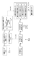
図1の全体構成図を参照して、車両の自動制動装置JSの実施形態について説明する。マスタシリンダCMは、マスタシリンダ流体路HM、及び、ホイールシリンダ流体路HWを介して、ホイールシリンダCWに接続されている。流体路は、自動制動装置JSの作動液体である制動液BFを移動するための経路であり、制動配管、流体ユニットの流路、ホース等が該当する。流体路の内部には、制動液BFが満たされている。流体路において、マスタシリンダCMに近い側が「上部」と称呼され、ホイールシリンダCWに近い側が「下部」と称呼される。
図1の全体構成図を参照して、車両の自動制動装置JSの実施形態について説明する。マスタシリンダCMは、マスタシリンダ流体路HM、及び、ホイールシリンダ流体路HWを介して、ホイールシリンダCWに接続されている。流体路は、自動制動装置JSの作動液体である制動液BFを移動するための経路であり、制動配管、流体ユニットの流路、ホース等が該当する。流体路の内部には、制動液BFが満たされている。流体路において、マスタシリンダCMに近い側が「上部」と称呼され、ホイールシリンダCWに近い側が「下部」と称呼される。
車両には、2系統の流体路(即ち、2つの制動系統)が採用される。2つの制動系統のうちの前輪系統(前輪マスタシリンダ室Rmfに係る系統)は、右前輪、左前輪ホイールシリンダCWi、CWj(=CWf)に接続される。また、2つの制動系統のうちの後輪系統(後輪マスタシリンダ室Rmrに係る系統)は、右後輪、左後輪ホイールシリンダCWk、CWl(=CWr)に接続される。車両の2つの制動系統として、所謂、前後型(「II型」ともいう)のものが採用されている。
自動制動装置JSを備える車両には、制動操作部材BP、ホイールシリンダCW、マスタリザーバRV、マスタシリンダCM、及び、ブレーキブースタBBが備えられる。
制動操作部材(例えば、ブレーキペダル)BPは、運転者が車両を減速するために操作する部材である。制動操作部材BPが操作されることによって、ホイールシリンダCWの液圧(制動液圧)Pwが調整され、車輪WHの制動トルクTqが調整される。その結果、車輪WHに制動力が調整される。
車両の車輪WHには、回転部材(例えば、ブレーキディスク)KTが固定される。そして、回転部材KTを挟み込むようにブレーキキャリパが配置される。ブレーキキャリパには、ホイールシリンダCWが設けられ、その内部の制動液BFの圧力(制動液圧)Pwが増加されることによって、摩擦部材(例えば、ブレーキパッド)が、回転部材KTに押し付けられる。回転部材KTと車輪WHとは、一体的に回転するよう固定されているため、このときに生じる摩擦力によって、車輪WHに制動トルクTqが発生される。制動トルクTqによって、車輪WHに減速スリップが発生され、その結果、制動力が生じる。
マスタリザーバ(大気圧リザーバであり、単に、「リザーバ」ともいう)RVは、作動液体用のタンクであり、その内部に制動液BFが貯蔵されている。マスタシリンダCMは、制動操作部材BPに、ブレーキロッド、クレビス(U字リンク)等を介して、機械的に接続されている。マスタシリンダCMは、タンデム型であり、マスタピストンPLf、PLrによって、その内部が、前輪、後輪マスタシリンダ室Rmf、Rmrに分けられている。制動操作部材BPが操作されていない場合には、マスタシリンダCMのマスタシリンダ室Rmf、RmrとリザーバRVとは連通状態にある。マスタシリンダCMには、前輪、後輪マスタシリンダ流体路HMf、HMrが接続されている。制動操作部材BPが操作されると、2つのマスタピストンPLf、PLrが前進し、2つのマスタシリンダ室Rmf、Rmrは、リザーバRVから遮断される。制動操作部材BPの操作が増加されると、制動液BFは、マスタシリンダCMから、前輪、後輪マスタシリンダ流体路HMf、HMrを介して、4つのホイールシリンダCWi~CWlに向けて圧送される。
ブレーキブースタ(単に、「ブースタ」ともいう)BBによって、運転者による制動操作部材BPの操作力Fpが軽減される。ブースタBBとして、負圧式のものが採用される。負圧は、エンジン、又は、電動負圧ポンプにて形成される。ブースタBBとして、電気モータを駆動源とするものが採用されてもよい。
車両の各車輪WHには、車輪速度Vwを検出するよう、車輪速度センサVWが備えられる。車輪速度Vwの信号は、車輪WHのロック傾向(即ち、過大な減速スリップ)を抑制するアンチスキッド制御(アンチロックブレーキ制御)等の各輪独立の制動制御に利用される。
操舵操作部材(例えば、ステアリングホイール)には、操舵角Saを検出するように操舵角センサSAが備えられる。車両の車体には、ヨーレイト(ヨー角速度)Yrを検出するよう、ヨーレイトセンサYRが備えられる。また、車両の前後方向(進行方向)の加速度(前後加速度)Gx、及び、横方向(進行方向に直角な方向)の加速度(横加速度)Gyを検出するよう、前後加速度センサGX、及び、横加速度センサGYが設けられる。これらの信号(Sa、Yr等)は、過大なオーバステア挙動、アンダステア挙動を抑制する車両安定化制御(所謂、ESC)等の車両運動制御に用いられる。
運転者による制動操作部材BP(ブレーキペダル)の操作量Baを検出するよう、制動操作量センサBAが設けられる。制動操作量センサBAとして、マスタシリンダCM内の液圧(マスタシリンダ液圧)Pmを検出するマスタシリンダ液圧センサPM、制動操作部材BPの操作変位Spを検出する操作変位センサSP、及び、制動操作部材BPの操作力Fpを検出する操作力センサFPのうちの少なくとも1つが採用される。つまり、操作量センサBAによって、制動操作量Baとして、マスタシリンダ液圧Pm、操作変位Sp、及び、操作力Fpのうちの少なくとも1つが検出される。
上記の各センサ(VW等)によって検出された車輪速度Vw、操舵角Sa、ヨーレイトYr、前後加速度(減速度)Gx、横加速度Gy、制動操作量Ba(Pm、Sp、Fp)等の信号は、制動コントローラECUに入力される。
車両には、障害物との衝突を回避、又は、衝突時の被害を軽減するよう、運転支援システムが備えられる。運転支援システムは、距離センサOB、及び、運転支援コントローラECJを含んで構成される。距離センサOBによって、自車両の前方に存在する物体(他車両、固定物、人、自転車、等)と、自車両との間の距離(相対距離)Obが検出される。例えば、距離センサOBとして、カメラ、レーダ等が採用される。相対距離Obは、運転支援コントローラECJに入力される。運転支援コントローラECJでは、相対距離Obに基づいて、要求減速度Gsが演算される。要求減速度Gsは、車両が物体にぶつかることを回避するための、車両減速度の目標値である。要求減速度Gsは、通信バスBSを介して、制動コントローラECUに送信される。
≪制動コントローラECU≫
自動制動装置JSは、制動コントローラECU、及び、流体ユニットHUにて構成される。制動コントローラ(「電子制御ユニット」ともいう)ECUは、マイクロプロセッサMP等が実装された電気回路基板と、マイクロプロセッサMPにプログラムされた制御アルゴリズムにて構成されている。制動コントローラECUは、車載の通信バスBSを介して、信号(検出値、演算値等)を共有するよう、他のコントローラ(運転支援コントローラECJ等)とネットワーク接続されている。例えば、制動コントローラECUにて車体速度Vxが演算され、それが、運転支援コントローラECJに送信される。一方、運転支援コントローラECJから、制動コントローラECUには、自動制動制御(障害物との衝突回避、又は、衝突被害の軽減を達成する制動制御)を実行するための要求減速度Gs(目標値)が送信される。制動コントローラECUでは、要求減速度Gsに基づいて自動制動制御が実行される。
自動制動装置JSは、制動コントローラECU、及び、流体ユニットHUにて構成される。制動コントローラ(「電子制御ユニット」ともいう)ECUは、マイクロプロセッサMP等が実装された電気回路基板と、マイクロプロセッサMPにプログラムされた制御アルゴリズムにて構成されている。制動コントローラECUは、車載の通信バスBSを介して、信号(検出値、演算値等)を共有するよう、他のコントローラ(運転支援コントローラECJ等)とネットワーク接続されている。例えば、制動コントローラECUにて車体速度Vxが演算され、それが、運転支援コントローラECJに送信される。一方、運転支援コントローラECJから、制動コントローラECUには、自動制動制御(障害物との衝突回避、又は、衝突被害の軽減を達成する制動制御)を実行するための要求減速度Gs(目標値)が送信される。制動コントローラECUでは、要求減速度Gsに基づいて自動制動制御が実行される。
制動コントローラECU(電子制御ユニット)によって、流体ユニットHUの電気モータML、及び、3種類の異なる電磁弁UP、VI、VOが制御される。具体的には、マイクロプロセッサMP内の制御アルゴリズムに基づいて、各種電磁弁UP、VI、VOを制御するための駆動信号Up、Vi、Voが演算される。同様に、電動ポンプDLの駆動源である電気モータMLを制御するための駆動信号Mlが演算される。
制動コントローラECUには、電磁弁UP、VI、VO、及び、電気モータMLを駆動するよう、駆動回路DRが備えられる。駆動回路DRには、電気モータMLを駆動するよう、スイッチング素子(MOS-FET、IGBT等のパワー半導体デバイス)によってブリッジ回路が形成される。モータ駆動信号Mlに基づいて、各スイッチング素子の通電状態が制御され、電気モータMLの出力が制御される。また、駆動回路DRでは、電磁弁UP、VI、VOを駆動するよう、駆動信号Up、Vi、Voに基づいて、スイッチング素子によって、それらの通電状態(即ち、励磁状態)が制御される。なお、駆動回路DRには、電気モータML、及び、電磁弁UP、VI、VOの実際の通電量を検出する通電量センサが設けられる。例えば、通電量センサとして、電流センサが設けられ、電気モータML、及び、電磁弁UP、VI、VOへ供給される電流値(通電量)が検出される。
≪流体ユニットHU≫
流体ユニットHUは、前輪、後輪マスタシリンダ流体路HMf、HMrに接続される。流体ユニットHU内の部位Btf、Btr(分岐部)にて、2つのマスタシリンダ流体路HMf、HMrは、4つのホイールシリンダ流体路HWi~HWlに分岐され、4つのホイールシリンダCWi~CWlに接続される。車両には、前後型(「II型」ともいう)の制動系統が採用されている。流体ユニットHUは、調圧弁UP、電動ポンプDL、調圧リザーバRL、マスタシリンダ液圧センサPM、調整液圧センサPP、インレット弁VI、及び、アウトレット弁VOにて構成される。
流体ユニットHUは、前輪、後輪マスタシリンダ流体路HMf、HMrに接続される。流体ユニットHU内の部位Btf、Btr(分岐部)にて、2つのマスタシリンダ流体路HMf、HMrは、4つのホイールシリンダ流体路HWi~HWlに分岐され、4つのホイールシリンダCWi~CWlに接続される。車両には、前後型(「II型」ともいう)の制動系統が採用されている。流体ユニットHUは、調圧弁UP、電動ポンプDL、調圧リザーバRL、マスタシリンダ液圧センサPM、調整液圧センサPP、インレット弁VI、及び、アウトレット弁VOにて構成される。
前輪、後輪調圧弁UPf、UPr(=UP)が、前輪、後輪マスタシリンダ流体路HMf、HMr(=HM)に設けられる。調圧弁UPとして、通電状態(例えば、供給電流)に基づいて開弁量(リフト量)が連続的に制御されるリニア型の電磁弁(「比例弁」、又は、「差圧弁」ともいう)が採用される。調圧弁UPは、コントローラECUによって、前輪、後輪調圧弁駆動信号Upf、Upr(=Up)に基づいて制御される。ここで、前輪、後輪調圧弁UPf、UPrとして、常開型の電磁弁が採用される。
電動ポンプDLは、1つの電気モータML、及び、2つの流体ポンプQLf、QLr(=QL)にて構成される。電気モータMLは、コントローラECUによって、駆動信号Mlに基づいて制御される。電気モータMLによって、前輪、後輪流体ポンプQLf、QLrが一体となって回転され、駆動される。前輪、後輪流体ポンプQLf、QLrによって、前輪、後輪調圧弁UPf、UPrとマスタシリンダCMとの間(即ち、調圧弁UPの上部)に位置する、前輪、後輪吸込部Bsf、Bsrから制動液BFが汲み上げられる。汲み上げられた制動液BFは、前輪、後輪調圧弁UPf、UPrの下部に位置する、前輪、後輪吐出部Btf、Btrに吐出される。ここで、電動ポンプDLは、一方向に限って回転される。前輪、後輪流体ポンプQLf、QLrの吸込み側には、前輪、後輪調圧リザーバRLf、RLr(=RL)が設けられる。
コントローラECUにて、自動制動制御の演算結果(例えば、目標液圧Pt)に基づいて、調圧弁UPの目標通電量が演算され、これに基づいて駆動信号Upが決定される。そして、駆動信号Upに応じて、調圧弁UPへの通電量(電流)が調整され、調圧弁UPの開弁量が調整される。
流体ポンプQLが駆動されると、「Bs→RL→QL→Bt→UP→Bs」の還流(循環する制動液BFの流れ)が形成される。調圧弁UPへの通電が行われず、常開型の調圧弁UPが全開状態である場合には、調圧弁UPの上部の液圧(即ち、マスタシリンダ液圧Pm)と、調圧弁UPの下部の実際の液圧Pp(「調整液圧」という)とは一致する。
常開型の前輪、後輪調圧弁UPf、UPrへの通電量が増加され、その開弁量が減少される。前輪、後輪調圧弁UPf、UPrによって、制動液BFの還流が絞られ、オリフィス効果によって、前輪、後輪調整液圧(実液圧)Ppf、Ppr(=Pp)は、前輪、後輪マスタシリンダ液圧Pmf、Pmr(=Pm)から増加される(従って、「Pp>Pm」)。つまり、電動ポンプDL、及び、調圧弁UPによって、マスタシリンダ液圧Pmと調整液圧Ppとの間の差圧が調整される。電動ポンプDL、及び、調圧弁UPが制御されることによって、制動操作部材BPの操作に応じたマスタシリンダ液圧Pmよりも、調整液圧Pp(結果、ホイールシリンダCWの制動液圧Pw)が増加される。例えば、制動操作部材BPが操作されていない場合には、「Pm=0」であるが、自動制動制御によって、制動液圧Pwが「0」から上昇される。
調圧弁UPの上部(マスタシリンダCMに近い側)には、前輪、後輪マスタシリンダ液圧Pmf、Pmrを検出するよう、前輪、後輪マスタシリンダ液圧センサPM1、PM2が設けられる。なお、基本的には、「Pmf=Pmr」であるため、前輪、後輪マスタシリンダ液圧センサPM1、PM2のうちの一方は、省略可能である。
調圧弁UPの下部(ホイールシリンダCWに近い側)には、前輪、後輪調整液圧(前輪、後輪液圧)Ppf、Pprを検出するよう、前輪、後輪調整液圧センサPPf、PPrが設けられる。なお、調圧弁UPにおいて、通電量(供給電流)と差圧(マスタシリンダ液圧Pmと調整液圧Ppとの圧力差)との関係は既知であるため、前輪、後輪調整液圧センサPPf、PPrのうちの少なくとも1つは省略され得る。調圧弁UPへの通電量は、駆動信号Upによって調整されるため、例えば、2つの調整液圧センサPPが省略された場合には、駆動信号Up(即ち、調圧弁UPへの通電量)に基づいて、調整液圧Ppが推定され得る。
ホイールシリンダ流体路HWi~HWlには、インレット弁VIi~VIlが設けられる。ホイールシリンダ流体路HWは、インレット弁VIの下部(インレット弁VIとホイールシリンダCWとの間)にて、常閉型のアウトレット弁VOを介して、調圧リザーバRLに接続される。なお、ホイールシリンダ流体路HWと調圧リザーバRLとを接続する流体路が、「リザーバ流体路HR」と称呼される。従って、各アウトレット弁VOは、各リザーバ流体路HRに設けられる。
インレット弁VIとして、常開型のオン・オフ電磁弁が採用される。ここで、「オン・オフ電磁弁」は、開位置と閉位置の2つの位置を有する切替型電磁弁である。つまり、常開型のインレット弁VIでは、開位置と閉位置とが選択的に実現される。インレット弁VIの開弁状態は、デューティ比Duに基づいて演算された駆動信号Viによって調整される。ここで、「デューティ比」は、一定の周期で連続するパルス列において、パルスのオン時間(通電時間)の比率である。インレット弁VIは、常開型であるため、非通電時(Du=0%)には全開状態にされ、フル通電時(Du=100%)には全閉状態にされる。そして、デューティ比Duが、0%~100%の間で調整されることによって、インレット弁VIの開弁状態が調整され得る。
アウトレット弁VOとして、常閉型のオン・オフ電磁弁が採用される。従って、常閉型のアウトレット弁VOでも、開位置と閉位置とが選択的に実現される。インレット弁VIと同様に、アウトレット弁VOの開弁状態も、デューティ比Du(単位時間当たりの通電時間の割合)に基づいて演算された駆動信号Voによって調整される。アウトレット弁VOは、常閉型であるため、非通電時(Du=0%)には全閉状態にされ、フル通電時(Du=100%)には全開状態にされる。デューティ比Duが、0%~100%の間で調整されることによって、アウトレット弁VOの開弁状態(閉弁状態)が調整され得る。
インレット弁VI、及び、アウトレット弁VOにおいて、各車輪WHに係る構成は同じである。例えば、ホイールシリンダCW内の液圧Pwを減少するためには、インレット弁VIが閉位置にされ、アウトレット弁VOが開位置される。制動液BFのインレット弁VIからの流入が阻止され、ホイールシリンダCW内の制動液BFは、調圧リザーバRLに流出し、制動液圧Pwは減少される。また、制動液圧Pwを増加するため、インレット弁VIが開位置にされ、アウトレット弁VOが閉位置される。制動液BFの調圧リザーバRLへの流出が阻止され、調圧弁UPによって調節された調整液圧Ppが、ホイールシリンダCWに導入され、制動液圧Pwが増加される。更に、ホイールシリンダCW内の液圧(制動液圧)Pwを保持するためには、インレット弁VI、及び、アウトレット弁VOが、共に閉位置にされる。つまり、電磁弁UP、VI、VOを制御することによって、制動液圧Pwi~Pwl(結果、制動トルクTqi~Tql)は各輪独立で調整可能である。
<運転支援コントローラECJ、及び、制動コントローラECUでの演算処理>
図2の機能ブロック図を参照して、運転支援コントローラECJ、及び、制動コントローラECUでの演算処理について説明する。運転支援コントローラECJによって、自動制動制御での要求減速度Gsが演算される。要求減速度Gsは、通信バスBSを介して、制動コントローラECUに送信される。制動コントローラECUでは、要求減速度Gsに基づいて、各車輪WHの制動液圧Pw(即ち、制動トルクTq)を調整するよう、流体ユニットHU(ML、UP等)が制御される。
図2の機能ブロック図を参照して、運転支援コントローラECJ、及び、制動コントローラECUでの演算処理について説明する。運転支援コントローラECJによって、自動制動制御での要求減速度Gsが演算される。要求減速度Gsは、通信バスBSを介して、制動コントローラECUに送信される。制動コントローラECUでは、要求減速度Gsに基づいて、各車輪WHの制動液圧Pw(即ち、制動トルクTq)を調整するよう、流体ユニットHU(ML、UP等)が制御される。
車両には、自車両が走行している先に存在する物体(他の車両、固定物、自転車、人、動物等)と、自車両との間の距離(相対距離)Obを検出するよう、距離センサOBが設けられる。例えば、距離センサOBとして、カメラ、レーダ等が利用される。また、固定物が地図情報に記憶されている場合には、距離センサOBとして、ナビゲーションシステムが利用され得る。検出された相対距離Obは、運転支援コントローラECJに入力される。運転支援コントローラECJには、衝突余裕時間演算ブロックTC、車頭時間演算ブロックTW、及び、要求減速度演算ブロックGSが含まれる。
衝突余裕時間演算ブロックTCにて、車両前方の物体と自車両との相対的な距離Obに基づいて、衝突余裕時間Tcが演算される。衝突余裕時間Tcは、自車両と物体とが衝突に至るまでの時間である。具体的には、衝突余裕時間Tcは、車両前方の物体と自車両との相対的な距離Obが、障害物と自車両との速度差(即ち、相対速度)によって除算されることによって決定される。ここで、相対速度は、相対距離Obが時間微分されて演算される。
車頭時間演算ブロックTWにて、相対距離Ob、及び、車体速度Vxに基づいて、車頭時間Twが演算される。車頭時間Twは、前方の物体の現在位置に自車両が到達するまでの時間である。具体的には、車頭時間Twは、相対距離Obが、車体速度Vxにて除算されて演算される。なお、自車両前方の物体が静止している場合には、衝突余裕時間Tcと車頭時間Twとは一致する。車体速度Vxは、制動コントローラECUの車体速度演算ブロックVXから、通信バスBSを介して取得される。
要求減速度演算ブロックGSにて、衝突余裕時間Tc、及び、車頭時間Twに基づいて、要求減速度Gsが演算される。要求減速度Gsは、自車両と前方物体との衝突を回避するための自車両の減速度の目標値である。要求減速度Gsは、演算マップZgsに従って、衝突余裕時間Tcが大きいほど、小さくなるよう(又は、衝突余裕時間Tcが小さいほど、大きくなるよう)、演算される。また、要求減速度Gsは、車頭時間Twに基づいて調整され得る。車頭時間Twが大きいほど、要求減速度Gsが小さくなるよう(又は、車頭時間Twが小さいほど、要求減速度Gsが大きくなるよう)、車頭時間Twに基づいて、要求減速度Gsが調整される。要求減速度Gsは、通信バスBSを介して、制動コントローラECUに入力される。
車両の各車輪WHには、車輪WHの回転速度(車輪速度)Vwを検出するよう、車輪速度センサVWが設けられる。検出された車輪速度Vwは、制動コントローラECUに入力される。制動コントローラECUには、車体速度演算ブロックVX、実減速度演算ブロックGA、自動制動制御ブロックJC、及び、駆動回路DRが含まれる。
車体速度演算ブロックVXにて、車輪速度Vwに基づいて、車体速度Vxが演算される。例えば、車両の加速時を含む非制動時には、4つの車輪速度Vwのうちの最も遅いもの(最遅の車輪速度)に基づいて、車体速度Vxが演算される。また、制動時には、4つの車輪速度Vwのうちの最も速いもの(最速の車輪速度)に基づいて、車体速度Vxが演算される。更に、車体速度Vxの演算において、その時間変化量において制限が設けられ得る。即ち、車体速度Vxの増加勾配の上限値αup、及び、減少勾配の下限値αdnが設定され、車体速度Vxの変化が、上下限値αup、αdnによって制約される。演算された車体速度Vxは、通信バスBSを介して、運転支援コントローラECJの車頭時間演算ブロックTWに送信される。
実減速度演算ブロックGAにて、車体速度Vxに基づいて、実減速度Gaが演算される。実減速度Gaは、実際に発生している車両の前後方向(進行方向)の減速度(負の加速度)である。具体的には、車体速度Vxが時間微分されて、実減速度Gaが演算される。また、実減速度Gaの演算に、前後加速度(減速度)Gxが採用される。この場合、実減速度Gaとして、前後加速度Gx(検出値)が、そのまま決定される。前後加速度Gxは、前後加速度センサGXによって検出されるが、前後加速度Gxには、走行路面の勾配が含まれる。このため、実減速度Gaの演算には、前後加速度Gxよりも、車体速度Vxの微分値の方が好ましい。また、ロバスト性を向上するよう、車体速度Vxの微分値(演算値)、及び、前後加速度Gx(検出値)に基づいて、実際の車両減速度Gaが演算されてもよい。つまり、車両の実際の減速度Gaは、車輪速度センサVW、及び、前後加速度センサGXのうちの少なくとも一方の検出結果に基づいて演算される。
自動制動制御ブロックJCにて、要求減速度Gs、及び、実減速度Gaに基づいて、自動制動制御が実行される。先ず、自動制動制御ブロックJCでは、自動制動の要否が判定される。運転者が既に制動操作部材BPを操作しており、実減速度Gaが要求減速度Gsよりも大きい場合には、自動制動制御は不要である。一方、実減速度Gaが要求減速度Gsよりも小さい場合に、実減速度Gaが、要求減速度Gsに一致するよう、車両の減速度に基づくフィードバック制御(自動制動制御)が実行される。自動制動制御ブロックJCは、偏向状態量演算ブロックHA、偏向方向演算ブロックDA、目標液圧演算ブロックPT、及び、駆動信号演算ブロックDSが含まれる。
偏向状態量ブロックHAでは、先ず、ヨーレイトYrに応じた実旋回量Ya、及び、操舵角Saに応じた規範旋回量Ysが演算される。そして、実旋回量Ya、及び、規範旋回量Ysに基づいて、それらの偏差が偏向状態量Haとして演算される(即ち、「Ha=Ya-Ys」)。「偏向状態量Ha」は、車両の偏向の程度(度合い)を表す状態変数である。つまり、偏向状態量Haは、操舵角Saによって指示された車両の進行方向(規範値)と、実際の車両進行方向(実際値)との差(即ち、車両偏向)の程度を表す。
偏向方向演算ブロックDAでは、車両の偏向が発生している場合(例えば、偏向状態量Haが所定量hx以上の場合)に、ヨーレイトYrに基づいて、車両が偏向する方向(旋回方向)Daが判定(識別)される。ここで、所定量hxは、予め設定された定数(判定しきい値)である。具体的には、偏向方向Daの判定演算は、車両が直進走行している場合(詳細には、操舵角Saが略中立位置にあって、所定角saの範囲内である場合)に、ヨーレイトYrの符号に基づき行われる。例えば、ヨーレイトYrの正符号(+)である場合には偏向方向Daが左方向であり、ヨーレイトYrの負符号(-)である場合には偏向方向Daが右方向であることが演算される。また、偏向方向Daは、偏向状態量Haの符号に応じて演算されてもよい。いずれにしても、車両の偏向はヨーレイトYrの変化に現れるため、偏向方向Daは、ヨーレイトYrに基づいて識別される。
偏向方向演算ブロックDAでは、偏向方向Daに基づいて、各車輪WHが、偏向方向Daに対して、「外側に位置するか、内側に位置するか」が判定される。例えば、偏向方向Daが左方向である場合には、右側前後輪WHi、WHkが偏向外側の車輪WHfs、WHrsに、左側前後輪WHj、WHlが偏向内側の車輪WHfu、WHruに決定される。逆に、偏向方向Daが右方向である場合には、左側前後輪WHj、WHlが偏向外側の車輪WHfs、WHrsに、右側前後輪WHi、WHkが偏向内側の車輪WHfu、WHruに決定される。
目標液圧演算ブロックPTにて、要求減速度Gs、実減速度Ga、偏向状態量Ha、偏向方向Da、及び、予め設定された演算マップZps、Zpa、Zpbに基づいて、各車輪の目標液圧Ptが演算される。目標液圧Ptの演算方法については後述する。
駆動信号演算ブロックDSでは、目標液圧Ptに基づいて、モータ駆動信号Ml、調圧弁駆動信号Up、及び、インレット弁、アウトレット弁駆動信号Vi、Voが演算される。例えば、目標液圧Ptに基づいて、電気モータMLの目標回転数が決定され、それが達成されるよう、電気モータMLへの通電量(電流値)を指示する駆動信号Ml(電流指示値)が演算される。また、電気モータMLは、予め設定された一定の回転数で駆動されてもよい。この場合には、モータ駆動信号Mlとして、電気モータMLの回転指示を行うための、オン信号が決定される。更に、制動液圧Pwが、目標液圧Ptに近づき、一致するように、電磁弁駆動信号Up、Vi、Voが決定される。駆動信号Ml、Up、Vi、Voは、駆動回路DRに送信される。
駆動回路DRでは、駆動信号Ml、Up、Vi、Voに基づいて、スイッチング素子(パワー半導体デバイス)によって、電気モータML、及び、電磁弁UP、VI、VOの通電状態が制御される。駆動回路DRには、電気モータML、及び、調圧弁UPの実際の通電量(供給電流値)を検出する通電量センサ(電流センサ)が設けられ、供給電流値が、駆動信号Ml、Upに一致するよう、電流フィードバック制御が実行される。加えて、駆動回路DRでは、スイッチング素子によって、駆動信号Vi、Voによって、オン・オフ電磁弁VI、VOの通電状態が制御され、それらの開弁状態(閉弁状態)が調整される。これにより、制動液圧Pwi~Pwlが、個別に制御され、その結果、車輪WHi~WHlの制動トルクTqi~Tqlが独立して調整される。なお、右前輪WHiの制動トルクTqiが「第1制動トルク」に、左前輪WHjの制動トルクTqjが「第2制動トルク」に、夫々相当する。
<自動制動制御の演算処理>
図3のフロー図を参照して、自動制動制御の演算処理について説明する。自動制動制御は、車両の前方の物体(障害物)と、車両との相対距離Obに応じた要求減速度Gsに基づいて、車両と障害物との衝突を回避等するよう、ホイールシリンダCWの液圧(制動液圧)PwをマスタシリンダCMの液圧(マスタシリンダ液圧)Pm以上に増加する。つまり、自動制動制御は、車両と障害物との衝突の蓋然性が高い場合(即ち、緊急時)に、所定の減速度以上の急制動を実行する。例えば、自動制動制御は、車輪と路面との摩擦係数の上限に近い領域であって、常用制動(通常の制動時)よりも極めて高い減速度(例えば、0.7~0.8G以上)で作動する。
図3のフロー図を参照して、自動制動制御の演算処理について説明する。自動制動制御は、車両の前方の物体(障害物)と、車両との相対距離Obに応じた要求減速度Gsに基づいて、車両と障害物との衝突を回避等するよう、ホイールシリンダCWの液圧(制動液圧)PwをマスタシリンダCMの液圧(マスタシリンダ液圧)Pm以上に増加する。つまり、自動制動制御は、車両と障害物との衝突の蓋然性が高い場合(即ち、緊急時)に、所定の減速度以上の急制動を実行する。例えば、自動制動制御は、車輪と路面との摩擦係数の上限に近い領域であって、常用制動(通常の制動時)よりも極めて高い減速度(例えば、0.7~0.8G以上)で作動する。
ステップS110にて、各種信号が読み込まれる。具体的には、要求減速度Gs、前後加速度Gx(検出値)、及び、車体速度Vxが取得される。ステップS120にて、前後加速度(検出値)Gx、及び、車体速度Vxのうちの少なくとも1つに基づいて、実際に発生している車両前後方向の減速度Gaが演算される。
ステップS130にて、自動制動制御の要否が判定される。具体的には、自動制動制御の要否は、要求減速度Gsと実減速度Gaとの比較に基づいて判定される。運転者によって十分な車両減速が行われ、要求減速度Gsが実減速度Ga以下である場合(即ち、「Gs≦Ga」)には、自動制動制御は不要であるため、処理は、ステップS110に戻される。一方、運転者によって十分な車両減速が行われておらず、要求減速度Gsが実減速度Gaよりも大きい場合(即ち、「Gs>Ga」)には、自動制動制御が必要であるため、処理は、ステップS140に進められる。
ステップS150にて、要求減速度Gs、及び、要求液圧ブロックPSに示す演算マップZpsに基づいて、要求液圧Psが決定される。要求液圧Psは、実際の調整液圧Ppについての目標値である。要求液圧Psは、予め設定された演算マップZpsに基づいて、要求減速度Gsが増加するほど、要求液圧Psが、マスタシリンダ液圧Pmから増加するように演算される。例えば、制動操作部材BPが操作されていない場合には、「Pm=0」であるため、要求減速度Gsが「0」から増加するに従って、要求液圧Psは、「0」から増加するように演算される。なお、要求液圧Psは、各ホイールシリンダCWにおいて、等しい値に決定される(即ち、「Psi=Psj=Psk=Psl」)。
ステップS160にて、操舵角Sa、ヨーレイトYr、及び、車体速度Vxに基づいて、偏向状態量Haが演算される。偏向状態量Haは、車両偏向(操舵角Saによって指示された車両が進行すべき方向と、実際に車両が進行している方向との差)の程度を表現する状態変数である。例えば、偏向状態量Haは、車両の偏向方向Daが考慮されて、以下の式(1)にて演算される。
Ha=sgn(Yr)・(Ya-Ys) …式(1)
ここで、関数「sgn」は、符号関数(「シグナム関数」ともいう)であり、引数の符号に応じて、「1」、「-1」、「0」のいずれかを返す関数である。例えば、左方向への偏向を正符号(+)、右方向への偏向を負符号(-)とすると、偏向方向Daが、左方向の場合には「sgn(Yr)=1」が、右方向の場合には「sgn(Yr)=-1」が演算される。従って、車両が直進走行している状態(即ち、「Sa=Ys=0」)で左方向に偏向する場合には、「sgn(Yr)」は正符号(+)、且つ、「Ya-Ys」は正符号(+)になるため、「Ha」は正符号(+)になる。逆に、右方向に偏向する場合には、「sgn(Yr)」は負符号(-)、且つ、「Ya-Ys」は負符号(-)になるため、「Ha」は正符号(+)になる。
Ha=sgn(Yr)・(Ya-Ys) …式(1)
ここで、関数「sgn」は、符号関数(「シグナム関数」ともいう)であり、引数の符号に応じて、「1」、「-1」、「0」のいずれかを返す関数である。例えば、左方向への偏向を正符号(+)、右方向への偏向を負符号(-)とすると、偏向方向Daが、左方向の場合には「sgn(Yr)=1」が、右方向の場合には「sgn(Yr)=-1」が演算される。従って、車両が直進走行している状態(即ち、「Sa=Ys=0」)で左方向に偏向する場合には、「sgn(Yr)」は正符号(+)、且つ、「Ya-Ys」は正符号(+)になるため、「Ha」は正符号(+)になる。逆に、右方向に偏向する場合には、「sgn(Yr)」は負符号(-)、且つ、「Ya-Ys」は負符号(-)になるため、「Ha」は正符号(+)になる。
例えば、偏向状態量Ha(ヨーレイト偏差)は、物理量として、ヨーレイトYrが採用されて、演算される。この場合、規範旋回量Ysは、操舵角Sa、及び、車体速度Vxに基づいて、車両のホイールベースを「L」、スタビリティファクタを「Kh」としたときに、以下の式(2)にて計算される。
Ys=(Vx^2×Sa)/{L×(1+Kh・Vx^2)}…式(2)
また、実旋回量Yaは、ヨーレイトセンサYRにて検出されたヨーレイトYrが、そのまま、用いられる。ここで、規範旋回量Ysは、車両偏向が生じていない場合に対応する。
Ys=(Vx^2×Sa)/{L×(1+Kh・Vx^2)}…式(2)
また、実旋回量Yaは、ヨーレイトセンサYRにて検出されたヨーレイトYrが、そのまま、用いられる。ここで、規範旋回量Ysは、車両偏向が生じていない場合に対応する。
式(2)で示すように、車輪WHがグリップしている状態では、操舵角SaとヨーレイトYrとは、所定の関係にある。このため、偏向状態量Ha(操舵角偏差)は、物理量として、操舵角Saの次元で演算され得る。この場合、規範旋回量Ysとして、操舵角Saが、そのまま、決定される。そして、実旋回量Yaは、以下の式(3)にて演算される。
Ya={L×(1+Kh・Vx^2)}×Yr/(Vx^2)…式(3)
何れにしても、偏向状態量Haは、操舵角Saに応じた規範旋回量Ysと、ヨーレイトYrに応じた実旋回量Yaとの差として演算される。
Ya={L×(1+Kh・Vx^2)}×Yr/(Vx^2)…式(3)
何れにしても、偏向状態量Haは、操舵角Saに応じた規範旋回量Ysと、ヨーレイトYrに応じた実旋回量Yaとの差として演算される。
ステップS160にて、実減速度Gaに基づいて、「後輪制動力の不足等が生じる蓋然性が高いか、否か」が判定される。具体的には、「実減速度Gaが所定減速度gx以上であるか、否か」が判定される。ここで、所定減速度gxは、車両減速によって、後輪荷重が減少し、後輪制動力が不足するとともに、車体のピッチング挙動が過大となる状態を判定するためのしきい値であって、予め設定された定数(所定値)である。「Ga<gx」であり、ステップS160が否定される場合には、処理はステップS180に進められる。一方、「Ga≧gx」であり、ステップS160が肯定される場合には、処理はステップS170に進められる。
ステップS170にて、偏向状態量Haに基づいて、「車両偏向が生じているか、否か」が判定される。具体的には、「偏向状態量Haが所定量hx以上であるか、否か」が判定される。ここで、所定量hxは、車両の偏向(ふらつき)を判定するためのしきい値であって、予め設定された定数(所定値)である。「Ha<hx」であり、ステップS170が否定される場合には、処理はステップS190に進められる。一方、「Ha≧hx」であり、ステップS170が肯定される場合には、処理はステップS200に進められる。
ステップS180にて、前輪要求液圧Psfが、前輪目標液圧Ptfとして演算されるとともに、後輪要求液圧Psrが、後輪目標液圧Ptrとして演算される(即ち、「Ptf=Psf、Ptr=Psr」)。ここで、目標液圧Ptは、最終的な制動液圧Pwの目標値である。ステップS180の処理は、「後輪制動力の不足、過大なピッチング挙動、及び、車両偏向のいずれもが生じない場合」に対応する。ステップS180では、実減速度Gaが、要求減速度Gsに近づき、一致するように、要求液圧Psが、そのまま、目標液圧Ptとして演算される。例えば、各ホイールシリンダCWにおいて、目標液圧Ptが同じに決定され得る(即ち、「Pti=Ptj=Ptk=Ptl」)。つまり、各車輪WHに加えられる制動トルクTqは、左右輪間で同じである。
ステップS190にて、後輪要求液圧Psrが、後輪目標液圧Ptrとして演算される(即ち、「Ptr=Psr」)。一方、前輪目標液圧Ptfは、前輪要求液圧Psfから減少されて演算される。具体的には、実減速度Ga、及び、減少演算ブロックGNの演算マップZpaに基づいて、安定時減少量Paが演算される。「安定時減少量Pa」は、車両偏向が生じおらず、ヨー挙動において車両が安定状態にある場合において、前輪液圧Ptf(目標値)、Pwf(実際値であって、結果、第1、第2制動トルクTqi、Tqj)を減少するための状態変数である。
具体的には、ステップS190では、実減速度Gaから所定減速度gxが減算されて、減速度偏差hGが演算される。そして、安定時減少量Paは、演算マップZpaに従って、減速度偏差hGの増加に従って増加するように演算される。安定時減少量Paには、上限値paが設けられる。
前輪目標液圧Ptf(前輪の最終的な制動液圧の目標値)は、前輪要求液圧Psfから安定時減少量Paが減算されて決定される(即ち、「Ptf=Psf-Pa」)。ステップS190の処理は、「車両偏向は生じていないが、後輪制動力の不足、過大なピッチング挙動の蓋然性が高い場合」に対応する。このため、後輪要求液圧Psrは減少されず、そのまま、後輪目標液圧Ptr(後輪の最終的な制動液圧の目標値)として決定されるが、前輪要求液圧Psf(=Psi、Psj)が、安定時減少量Paだけ減少されて、前輪目標液圧Ptf(=Pti、Ptj)が決定される。しかしながら、車両偏向は発生していないので、右前輪目標液圧Pti(結果、第1制動トルクTqi)と、左前輪目標液圧Ptj(結果、第2制動トルクTqj)とは同じ値に決定される(即ち、「Pti=Ptj」)。後輪目標液圧Ptr(結果、後輪制動トルクTqr)が保持されたまま、前輪目標液圧Ptf(結果、前輪制動トルクTqf)が減少されるため、後輪制動力が有効に発生され、ピッチング挙動が安定化され得る。
ステップS200では、先ず、ヨーレイトYrに基づいて、車両が偏向している方向(旋回方向)Daが判定される。具体的には、偏向方向Daの判定は、ヨーレイトYrの正負符号(+又は-)に基づき行われる。また、偏向方向Daは、「Ya-Ys(実旋回量から規範旋回量を減算した状態量)」の正負符号に応じて識別されてもよい。つまり、車両の偏向はヨーレイトYrの変化に現れるため、偏向方向Daは、ヨーレイトYrに基づいて決定される。そして、偏向方向Daに基づいて、偏向方向Daの外側に対応する外側車輪(特に、外側前輪WHfs)と、偏向方向Daの内側に対応する内側車輪(特に、内側前輪WHfu)とが決定される。
そして、ステップS200では、ステップS180、S190と同様に、後輪要求液圧Psrが、後輪目標液圧Ptrとして演算される(即ち、「Ptr=Psr」)。一方、偏向外側の前輪目標液圧Ptfsは、前輪要求液圧Psfと同じに演算されるが、偏向内側の前輪目標液圧Ptfuは、前輪要求液圧Psfから減少されて演算される。具体的には、減速度偏差hG、偏向状態量Ha、及び、減少演算ブロックGNの演算マップZpbに基づいて、偏向時減少量Pbが演算される。「偏向時減少量Pb」は、車両偏向が生じている場合(「Ha≧hx」の場合)において、偏向内側の前輪液圧Ptfu(目標値)、Pwfu(実際値であって、即ち、内側制動トルクTqfu)を減少するための状態変数である。
偏向時減少量Pbは、演算マップZpbに従って、減速度偏差hG(=Ga-gx)の増加に従って増加するように演算される。また、偏向時減少量Pbは、演算マップZpbに応じて、偏向状態量Haが増加するに従って、増加するように演算される。そして、偏向時減少量Pbには、上限値pbが設けられる。ここで、同一の減速度偏差hGにおいて、偏向時減少量Pbは、安定時減少量Paよりも大きい値に決定される。偏向時減少量Pbは、減速度偏差hGに応じて変化するが、例えば、偏向時減少量Pbは、安定時減少量Paの2倍相当の値に決定される(即ち、「Pb≒2×Pa」)。これは、車両偏向が生じていない場合には、前2輪の制動力が減少されるが、車両偏向時には、偏向内側前輪WHfuの制動力のみが減少されることに基づく。
前輪要求液圧Psfは、そのまま、偏向外側前輪WHfsに対応する前輪目標液圧Ptfsとして決定される。しかし、偏向内側前輪WHfuに対応する前輪目標液圧Ptfuは、前輪要求液圧Psfから偏向時減少量Pbが減算されて演算される。つまり、「Ptfs=Psf、Ptfu=Psf-Pb」が演算されるため、結果、偏向外側の前輪制動トルクTqfsが保持され、偏向内側の前輪制動トルクTqfuのみが減少される。ステップS200の処理は、車両偏向が発生しているとともに、後輪制動力の不足、過大なピッチング挙動の蓋然性が高い場合に対応する。このため、偏向内側の前輪目標液圧Ptfu(結果、偏向内側の前輪制動トルクTqfu)が、偏向外側の前輪目標液圧Ptfs(結果、偏向外側の前輪制動トルクTqfs)よりも小さくなるように演算される。そして、この際に生じる前輪制動力の左右差によって、車両偏向が低減される。加えて、偏向外側の前輪目標液圧Ptfsは減少されないが、偏向内側の前輪目標液圧Ptfuが、安定時減少量Paよりも大きい値である偏向時減少量Pb(例えば、安定時減少量Paの2倍に相当する値)だけ減少されるため、ステップS190の処理と同様に、後輪制動力が有効に発生され、ピッチング姿勢が安定化され得る。
ステップS210にて、目標液圧Ptに基づいて、電気モータMLが駆動される。例えば、電気モータMLは、その最大出力で、急速に回転数が上昇するように駆動される。これにより、調圧弁UP、及び、流体ポンプQLを含む制動液BFの還流(「QL→Bt→UP→Bs→RL→QL」で循環する制動液BFの流れ)が形成される。そして、目標液圧Ptに基づいて、調整液圧Pp(実際値、又は、推定値)が、目標液圧Ptに近づき、一致するよう、電磁弁UPが制御される。或いは、調整液圧センサPPが省略された構成では、調圧弁UPへの通電量に対する、調整液圧Ppとマスタシリンダ液圧Pmとの差圧の関係は既知であるため、目標液圧Ptに応じた通電量が、調圧弁UPに供給される。そして、制動液圧Pwが、目標液圧Ptに一致するよう、インレット弁VI、及び、アウトレット弁VOが制御される。つまり、電磁弁UP、VI、VOの駆動制御によって、目標液圧Ptに一致するよう、制動液圧Pwが個別に調整される。ここで、「Ga≦gx」の場合には、電磁弁UP、VI、VOへの通電量制御において、実際の減速度Gaが、要求減速度Gsに一致するよう、減速度フィードバック制御が加えられてもよい。
<作用・効果>
自動制動装置JSは、車両の前方の物体と車両との距離Obに応じた要求減速度Gsに基づいて、車両の車輪WHの制動トルクTqを自動的に増加する。自動制動装置JSには、「車両の車輪速度(Vw)を検出する車輪速度センサVW、及び、車両の前後加速度Gxを検出する前後加速度センサGXのうちの少なくとも一方」と、「車両のヨーレイトYrを検出するヨーレイトセンサYR」と、「車両の右前輪WHiの制動液圧Pwi(即ち、第1制動トルクTqi)と車両の左前輪WHjの制動液圧Pwj(即ち、第2制動トルクTqj)とを個別に調整するアクチュエータHU」と、「アクチュエータHUを制御するコントローラECU」と、が備えられる。
自動制動装置JSは、車両の前方の物体と車両との距離Obに応じた要求減速度Gsに基づいて、車両の車輪WHの制動トルクTqを自動的に増加する。自動制動装置JSには、「車両の車輪速度(Vw)を検出する車輪速度センサVW、及び、車両の前後加速度Gxを検出する前後加速度センサGXのうちの少なくとも一方」と、「車両のヨーレイトYrを検出するヨーレイトセンサYR」と、「車両の右前輪WHiの制動液圧Pwi(即ち、第1制動トルクTqi)と車両の左前輪WHjの制動液圧Pwj(即ち、第2制動トルクTqj)とを個別に調整するアクチュエータHU」と、「アクチュエータHUを制御するコントローラECU」と、が備えられる。
コントローラECUは、車輪速度センサVW、及び、前後加速度センサGXのうちの少なくとも一方の検出結果(即ち、車輪速度Vw、及び、前後加速度Gxのうちの少なくとも1つ)に基づいて、車両の減速度Gaが演算されるとともに、ヨーレイトYrに基づいて、車両の偏向方向Da、及び、車両偏向の程度を表す偏向状態量Haが演算される。そして、「減速度Gaが所定減速度gx以上、且つ、偏向状態量Haが所定量hx未満である場合」には、第1、第2制動トルクTqi、Tqj(=Tqf、例えば、右前輪、左前輪制動液圧Pwi、Pwj)の両方が減少される。つまり、「Ha<hx」の場合には、前2輪の制動トルクが同量(安定時減少量Paに相当するトルク)だけ減少される。
一方、「減速度Gaが所定減速度gx以上、且つ、偏向状態量Haが所定量hx以上である場合」には、第1、第2制動トルク(前輪制動トルク)Tqi、Tqj(=Tqf)のうちで偏向方向Daの外側に対応する外側制動トルクTqfsが減少されずに保持され、第1、第2制動トルクTqi、Tqjのうちで偏向方向Daの内側に対応する内側制動トルクTqfuが減少される。つまり、「Ha≧hx」の場合には、内側制動トルクTqfuのみ(即ち、前輪のうちの1輪のみの制動トルク)が、偏向時減少量Pbに相当するトルク分だけ減少される。ここで、偏向状態量Haが大きいほど、内側制動トルクTqfuの減少量Pbが大きく決定されることが好適である。加えて、偏向時減少量Pbに相当するトルクは、安定時減少量Paに相当するトルクよりも大きく設定され得る(例えば、2倍)。
なお、「減速度Gaが所定減速度gx未満である場合」には、減速度Gaが要求減速度Gsに一致するよう、第1、第2制動トルクTqi、Tqj(=Tqf)は、増加、又は、保持される。具体的には、減速度Gaが所定減速度gx未満である場合には、先ず、第1、第2制動トルクTqi、Tqjが増加される。そして、「要求減速度Gsが所定減速度gx以下である場合」において、減速度Gaが要求減速度Gsに一致すると、第1、第2制動トルクTqi、Tqjは、一定に維持される。
図4の時系列線図を参照して、自動制動装置JSの作用・効果について説明する。図4(a)は車両偏向が発生していない場合に、図4(b)は車両偏向が発生している場合に、夫々対応している。線図では、運転者が制動操作部材BPを操作しておらず、自動制動装置JSによって、車両が自動的に急減速される状況(即ち、要求減速度Gsが所定減速度gxよりも大きい状況)が想定されている。時点t0、u0以前では、自動制動制御は開始されておらず、「Gs=0(結果、Ga=0)」である。目標液圧Ptは「0」であり、結果、制動液圧Pw(=Tq)は「0」である。
以下、図4(a)を参照して、ステップS190(ピッチング挙動が過大にはなるが、車両偏向は生じていない場合の処理)に対応した作動について説明する。時点t0にて、自動制動制御が開始され、要求減速度Gsが急激に増加される。自動制動制御が開始されると、電気モータMLが、その最大出力で駆動される。そして、要求減速度Gsの増加に応じて、前輪目標液圧Ptf(=Pti、Ptj)が同圧で急増され、結果、前輪制動液圧Pwf(=Pwi、Pwj)が急増される。前輪制動液圧Pwf(実際値)は、前輪目標液圧Ptfに一致するように制御されるため、線図では、前輪目標液圧Ptfと前輪制動液圧Pwfとは重なっている。つまり、時点t0から時点t1までは、実減速度Gaが所定減速度gx未満であるため、実減速度Gaが要求減速度Gsに一致するように、前輪目標液圧Ptf(=Pti、Ptj)が増加される(ステップS180を参照)。
時点t1にて、実減速度Gaが所定減速度gxを超過する。ステップS160の条件が満足されて、ステップS190の処理が開始される。時点t1から、前輪要求液圧Psf(=Psi、Psj)から、安定時減少量Paが減算されて、前輪目標液圧Ptf(=Pti、Ptj)が決定される(即ち、「Pti=Ptj=Psf-Pa」)。つまり、要求減速度Gsは増加されるが、前輪目標液圧Ptfは減少される(換言すれば、増加が制限される)。
安定時減少量Paは、演算マップZpaに応じて、減速度偏差hG(実減速度Gaが所定減速度gxを超過した分の減速度)が大きいほど、大きく演算される。従って、時点t1から、前輪目標液圧Ptfは、勾配Kgで減少され、前輪制動液圧Pwfは値pcから勾配Kgで減少される。なお、ステップS190では、「Ptr=Psr」が決定されるため、後輪制動液圧Pwr(=Pwk、Pwl)は、同圧の状態で、要求減速度Gsの増加に従って増加される。
実減速度Gaが適切に減少された時点t2にて、前輪目標液圧Ptfは、勾配Kzで増加され、前輪制動液圧Pwfは値pdから勾配Kzで増加される。この際、増加勾配Kgの大きさ(絶対値)は、減少勾配Kzの大きさ(絶対値)よりも大きい値に設定されている。前輪制動液圧Pwfの再増加に伴い、時点t3にて、実減速度Gaが所定減速度gxを超過すると、前輪制動液圧Pwfの再減圧が開始される。以降、前輪制動液圧Pwf(結果、前輪制動トルクTqf)の増減が繰り返され、実減速度Gaが所定減速度gxの近傍に維持される。実減速度Gaの増加において、前2輪WHfの制動液圧Pwf(=Pwi、Pwj)の増加が制限されることにより、後2輪WHrの荷重減少が抑制されるとともに、車両のピッチング姿勢が安定化され得る。ここで、車両偏向は生じていないため、左右の車輪間における制動トルクは同じである。
なお、要求減速度Gsが所定減速度gx未満である場合には、実減速度Gaが要求減速度Gsに一致すると、前輪目標液圧Ptfは、一定に維持される。結果、制動液圧Pwf(=Tqf)は保持される。
次に、図4(b)を参照して、ピッチング挙動が過大であって、車両偏向も生じている場合(即ち、「Ha≧hx」の場合)の処理である、ステップS200に対応した作動について説明する。線図では、左方向への車両偏向が想定されており、右前輪WHiが偏向外側前輪WHfsであり、左前輪WHjが偏向内側前輪WHfuである。上記同様に、時点u0にて、自動制動制御が開始され、要求減速度Gsが急激に(最終的には、所定減速度gx以上に)増加され、電気モータMLが最大出力で駆動される。そして、要求減速度Gsの増加に応じて、前輪目標液圧Ptf(=Pti、Ptj)が同圧で急増され、結果、前輪制動液圧Pwf(=Pwi、Pwj)が急増される。なお、前輪制動液圧Pwfは、前輪目標液圧Ptfに一致するように制御されるため、線図では、前輪目標液圧Ptfと前輪制動液圧Pwfとは重なっている。上記同様、時点u0~時点u1までは、「Ga<gx」であるため、「Ga=Gs」が達成されるように、前輪目標液圧Ptf(結果、前輪制動液圧Pwf)が増加される(ステップS180を参照)。
時点u1にて、実減速度Gaが所定減速度gxを超過し、且つ、偏向状態量Haが所定量hx以上となる。ステップS160、及び、ステップS170の条件が満足されて、ステップS200の処理が開始される。時点u1から、偏向内側前輪WHfuに対応する内側前輪目標液圧Ptfu(=Ptj)が、前輪要求液圧Psfから偏向時減少量Pb分だけ減算されることによって決定される。この際、偏向外側前輪WHfsに対応する外側前輪目標液圧Ptfs(=Pti)は、減少されることなく、前輪要求液圧Psfのままである。即ち、「Pti=Psf、Ptj=Psf-Pb」が演算される。時点u1以降は、要求減速度Gsは増加されるが、前輪目標液圧Ptfの増加は制限される。具体的には、内側前輪目標液圧Ptfu(=Ptj)が減少され、外側前輪目標液圧Ptfs(=Pti)が一定量pcに保持される。
偏向時減少量Pbは、演算マップZpbに応じて、減速度偏差hGが大きいほど、大きく演算されるとともに、偏向状態量Haの大きさ(絶対値)が大きいほど大きく演算される。従って、時点u1から、偏向内側前輪WHfuにおいて、目標液圧Ptfu(目標値)は勾配Keで減少され、結果、制動液圧Pwfu(実際値)は値pcから勾配Keで減少される。一方、偏向外側前輪WHfsにおいて、目標液圧Ptfsは減少されず、制動液圧Pwfuは値pcのままで保持される。なお、ステップS200でも、「Ptr=Psr」が決定され、後輪制動液圧Pwr(=Pwk、Pwl)は、要求減速度Gsの増加に従って同圧で増加される。
実減速度Gaが適度に減少された時点u2にて、内側前輪の目標液圧Ptfu(=Ptj)は勾配Kxで増加され、内側前輪の制動液圧Pwfu(=Pwj)は値peから勾配Kxで増加される。上記同様、減少勾配Keの大きさ(絶対値)は、増加勾配Kxの大きさ(絶対値)よりも大きい値に設定される。偏向内側の前輪制動液圧Pwfuの再増加に伴い、時点u3にて、実減速度Gaが所定減速度gxを再度超過すると、偏向内側の前輪制動液圧Pwfuの再減圧が開始される。以降、偏向内側の前輪制動液圧Pwfu(結果、偏向内側の前輪制動トルクTqfu)の増減が繰り返され、実減速度Gaが所定減速度gxの近傍に維持される。このとき、偏向外側の前輪目標液圧Ptfs(=Pti)は減少されず、保持されるため、偏向外側の前輪制動液圧Pwfs(「=Pwi」であって、外側制動トルクTqfs)は値pcで、一定に維持されている。実減速度Gaの増加制限において、偏向内側の前輪制動液圧Pwfu(即ち、内側制動トルクTqfu)のみが減少されるため、前輪制動力に左右差(結果、車両のヨー挙動を安定化するモーメント)が生じ、車両の偏向(ふらつき)が抑制される。更に、内側前輪制動液圧Pwfuの減少によって、実減速度Gaの増加が制限されるため、後輪WHrの荷重減少が抑制されるとともに、車両のピッチング挙動が安定化され得る。
上述した様に、偏向時減少量Pbは、安定時減少量Paよりも大きい値に決定される。例えば、偏向時減少量Pbは、安定時減少量Paの2倍程度の値に演算されるとよい。車両偏向が発生していても、車両偏向が生じていない場合と同程度の、実減速度Gaの増加制限効果を奏する。
なお、上記同様に、「Ga<gx」の状態では、「Ga=Gs」が達成されるよう、前輪目標液圧Ptf(=Tqf)は増加される。また、「Gs≦gx」の場合であって、「Ga=Gs」が達成された後には、前輪目標液圧Ptf(=Tqf)は、一定に保持される。
以上、作用・効果をまとめると、要求減速度Gsが所定減速度gxよりも大きい場合であっても、実減速度Gaが所定減速度gx以上になった場合には、2つの前輪WHfのうちの少なくとも1つの制動トルクが減少されるため、実減速度Gaが所定減速度gxの近傍に維持される。これにより、車両の過大なピッチング挙動が低減されるとともに、後輪制動力が有効に活用される。加えて、車両偏向の程度を表す偏向状態量Haが所定量hx以上の場合には、偏向外側車輪WHsの制動トルクTqsが一定量に維持された上で、偏向内側車輪WHuの制動トルクTquが減少される。これにより、前輪の制動トルク(制動力)の左右差によって、車両偏向を抑制するヨーモーメントが形成される。これにより、上記効果に加え、車両偏向が低減される。
<他の実施形態>
以下、他の実施形態について説明する。他の実施形態においても、上記同様の効果(車両のふらつき抑制、後輪制動力の有効利用、及び、車両のピッチング姿勢の安定化)を奏する。
以下、他の実施形態について説明する。他の実施形態においても、上記同様の効果(車両のふらつき抑制、後輪制動力の有効利用、及び、車両のピッチング姿勢の安定化)を奏する。
上記実施形態では、2系統流体路として、前後型流体路が例示された。これに代えて、ダイアゴナル型(「X型」ともいう)の構成が採用され得る。ダイアゴナル型流体路では、タンデム型マスタシリンダCMの第1室には、右前輪、左後輪ホイールシリンダCWi、CWlが接続される。また、マスタシリンダCMの第2室には、左前輪、右後輪ホイールシリンダCWj、CWkに接続される。
上記実施形態では、制動液BFによる液圧式の自動制動装置JSが例示された。これに代えて、制動液BFが用いられない、電動式の自動制動装置JSが採用され得る。該装置では、電気モータの回転が、ねじ機構等によって直線動力に変換され、摩擦部材が回転部材KTに押圧される。この場合には、制動液圧Pwに代えて、電気モータを動力源にして、回転部材KTに対する摩擦部材の押圧力が発生される。即ち、電気モータによって、制動トルクTqが付与され、車輪WHに制動力が発生される。
Claims (2)
- 車両の前方の物体と前記車両との距離に応じた要求減速度に基づいて、前記車両の車輪の制動トルクを自動的に増加する車両の自動制動装置であって、
前記車両の車輪速度を検出する車輪速度センサ、及び、前記車両の前後加速度を検出する前後加速度センサのうちの少なくとも一方と、
前記車両のヨーレイトを検出するヨーレイトセンサと、
前記車両の右前輪の第1制動トルクと前記車両の左前輪の第2制動トルクとを個別に調整するアクチュエータと、
前記アクチュエータを制御するコントローラと、
を備え、
前記コントローラは、
前記車輪速度センサ、及び、前記前後加速度センサのうちの少なくとも一方の検出結果に基づいて、前記車両の減速度を演算するとともに、
前記ヨーレイトに基づいて、前記車両の偏向方向、及び、前記車両の偏向の程度を表す偏向状態量を演算し、
前記減速度が所定減速度以上、且つ、前記偏向状態量が所定量未満である場合には、前記第1、第2制動トルクを減少し、
前記減速度が前記所定減速度以上、且つ、前記偏向状態量が前記所定量以上である場合には、前記第1、第2制動トルクのうちで前記偏向方向の外側に対応する外側制動トルクを保持し、前記第1、第2制動トルクのうちで前記偏向方向の内側に対応する内側制動トルクを減少する、車両の自動制動装置。 - 請求項1に記載の車両の自動制動装置において、
前記コントローラは、前記偏向状態量が大きいほど、前記内側制動トルクの減少量を大きく決定する、車両の自動制動装置。
Applications Claiming Priority (2)
| Application Number | Priority Date | Filing Date | Title |
|---|---|---|---|
| JP2019-020474 | 2019-02-07 | ||
| JP2019020474A JP7230550B2 (ja) | 2019-02-07 | 2019-02-07 | 車両の自動制動装置 |
Publications (1)
| Publication Number | Publication Date |
|---|---|
| WO2020162433A1 true WO2020162433A1 (ja) | 2020-08-13 |
Family
ID=71947698
Family Applications (1)
| Application Number | Title | Priority Date | Filing Date |
|---|---|---|---|
| PCT/JP2020/004057 Ceased WO2020162433A1 (ja) | 2019-02-07 | 2020-02-04 | 車両の自動制動装置 |
Country Status (2)
| Country | Link |
|---|---|
| JP (1) | JP7230550B2 (ja) |
| WO (1) | WO2020162433A1 (ja) |
Cited By (2)
| Publication number | Priority date | Publication date | Assignee | Title |
|---|---|---|---|---|
| WO2022074493A1 (ja) * | 2020-10-09 | 2022-04-14 | □ベルト・ボッシュ・ゲゼルシャフト・ミト・べシュレンクテル・ハフツング | 制御装置及び制御方法 |
| US20220340106A1 (en) * | 2019-08-09 | 2022-10-27 | Toyota Jidosha Kabushiki Kaisha | Drive assistance device |
Citations (4)
| Publication number | Priority date | Publication date | Assignee | Title |
|---|---|---|---|---|
| JP2005225482A (ja) * | 2004-01-15 | 2005-08-25 | Nissan Motor Co Ltd | 車両の制動制御方法及び装置 |
| JP2005335411A (ja) * | 2004-05-24 | 2005-12-08 | Toyota Motor Corp | 制動力制御装置 |
| JP2010047047A (ja) * | 2008-08-19 | 2010-03-04 | Advics Co Ltd | 車両の前後力制御装置 |
| JP2017149378A (ja) * | 2016-02-26 | 2017-08-31 | ダイハツ工業株式会社 | ブレーキ装置 |
-
2019
- 2019-02-07 JP JP2019020474A patent/JP7230550B2/ja active Active
-
2020
- 2020-02-04 WO PCT/JP2020/004057 patent/WO2020162433A1/ja not_active Ceased
Patent Citations (4)
| Publication number | Priority date | Publication date | Assignee | Title |
|---|---|---|---|---|
| JP2005225482A (ja) * | 2004-01-15 | 2005-08-25 | Nissan Motor Co Ltd | 車両の制動制御方法及び装置 |
| JP2005335411A (ja) * | 2004-05-24 | 2005-12-08 | Toyota Motor Corp | 制動力制御装置 |
| JP2010047047A (ja) * | 2008-08-19 | 2010-03-04 | Advics Co Ltd | 車両の前後力制御装置 |
| JP2017149378A (ja) * | 2016-02-26 | 2017-08-31 | ダイハツ工業株式会社 | ブレーキ装置 |
Cited By (4)
| Publication number | Priority date | Publication date | Assignee | Title |
|---|---|---|---|---|
| US20220340106A1 (en) * | 2019-08-09 | 2022-10-27 | Toyota Jidosha Kabushiki Kaisha | Drive assistance device |
| US11993237B2 (en) * | 2019-08-09 | 2024-05-28 | Toyota Jidosha Kabushiki Kaisha | Drive assistance device |
| WO2022074493A1 (ja) * | 2020-10-09 | 2022-04-14 | □ベルト・ボッシュ・ゲゼルシャフト・ミト・べシュレンクテル・ハフツング | 制御装置及び制御方法 |
| US12304442B2 (en) | 2020-10-09 | 2025-05-20 | Robert Bosch Gmbh | Controller and control method |
Also Published As
| Publication number | Publication date |
|---|---|
| JP7230550B2 (ja) | 2023-03-01 |
| JP2020128115A (ja) | 2020-08-27 |
Similar Documents
| Publication | Publication Date | Title |
|---|---|---|
| JP7135292B2 (ja) | 車両の制動制御装置 | |
| JP7345720B2 (ja) | 車両の自動制動装置 | |
| JP6984353B2 (ja) | 車両の制動制御装置 | |
| US20250178576A1 (en) | Braking control device for vehicle | |
| JP7395996B2 (ja) | 車両の自動制動装置 | |
| JP7230550B2 (ja) | 車両の自動制動装置 | |
| JP7047347B2 (ja) | 車両の制動制御装置 | |
| JP7452087B2 (ja) | 車両の制動制御装置 | |
| JP7139890B2 (ja) | 車両の自動制動装置 | |
| JP7259335B2 (ja) | 車両の自動制動装置 | |
| JP7363572B2 (ja) | 車両の制動制御装置 | |
| WO2023171812A1 (ja) | 車両の制動制御装置 | |
| JP7205164B2 (ja) | 車両の自動制動装置 | |
| JP2020111116A (ja) | 車両の自動制動装置 | |
| JP7302705B2 (ja) | 車両の制動制御装置 | |
| JP7139883B2 (ja) | 車両の制動制御装置 | |
| WO2019107522A1 (ja) | 車両の制動制御装置 | |
| JP2024120410A (ja) | 車両の制動制御装置 | |
| WO2024177156A1 (ja) | 車両の制動制御装置 | |
| WO2019181577A1 (ja) | 車両の制動制御装置 | |
| JP2019156347A (ja) | 車両の制動制御装置 | |
| JP2020157863A (ja) | 車両の自動制動装置 |
Legal Events
| Date | Code | Title | Description |
|---|---|---|---|
| 121 | Ep: the epo has been informed by wipo that ep was designated in this application |
Ref document number: 20752908 Country of ref document: EP Kind code of ref document: A1 |
|
| NENP | Non-entry into the national phase |
Ref country code: DE |
|
| 122 | Ep: pct application non-entry in european phase |
Ref document number: 20752908 Country of ref document: EP Kind code of ref document: A1 |