WO2020162173A1 - シールド部材 - Google Patents
シールド部材 Download PDFInfo
- Publication number
- WO2020162173A1 WO2020162173A1 PCT/JP2020/002078 JP2020002078W WO2020162173A1 WO 2020162173 A1 WO2020162173 A1 WO 2020162173A1 JP 2020002078 W JP2020002078 W JP 2020002078W WO 2020162173 A1 WO2020162173 A1 WO 2020162173A1
- Authority
- WO
- WIPO (PCT)
- Prior art keywords
- conductor
- electric wire
- ground
- shield
- auxiliary
- Prior art date
- Legal status (The legal status is an assumption and is not a legal conclusion. Google has not performed a legal analysis and makes no representation as to the accuracy of the status listed.)
- Ceased
Links
Images




Classifications
-
- H—ELECTRICITY
- H05—ELECTRIC TECHNIQUES NOT OTHERWISE PROVIDED FOR
- H05K—PRINTED CIRCUITS; CASINGS OR CONSTRUCTIONAL DETAILS OF ELECTRIC APPARATUS; MANUFACTURE OF ASSEMBLAGES OF ELECTRICAL COMPONENTS
- H05K9/00—Screening of apparatus or components against electric or magnetic fields
- H05K9/0073—Shielding materials
- H05K9/0081—Electromagnetic shielding materials, e.g. EMI, RFI shielding
-
- H—ELECTRICITY
- H02—GENERATION; CONVERSION OR DISTRIBUTION OF ELECTRIC POWER
- H02G—INSTALLATION OF ELECTRIC CABLES OR LINES, OR OF COMBINED OPTICAL AND ELECTRIC CABLES OR LINES
- H02G3/00—Installations of electric cables or lines or protective tubing therefor in or on buildings, equivalent structures or vehicles
- H02G3/02—Details
- H02G3/04—Protective tubing or conduits, e.g. cable ladders or cable troughs
-
- H—ELECTRICITY
- H05—ELECTRIC TECHNIQUES NOT OTHERWISE PROVIDED FOR
- H05K—PRINTED CIRCUITS; CASINGS OR CONSTRUCTIONAL DETAILS OF ELECTRIC APPARATUS; MANUFACTURE OF ASSEMBLAGES OF ELECTRICAL COMPONENTS
- H05K9/00—Screening of apparatus or components against electric or magnetic fields
- H05K9/0064—Earth or grounding circuit
-
- H—ELECTRICITY
- H05—ELECTRIC TECHNIQUES NOT OTHERWISE PROVIDED FOR
- H05K—PRINTED CIRCUITS; CASINGS OR CONSTRUCTIONAL DETAILS OF ELECTRIC APPARATUS; MANUFACTURE OF ASSEMBLAGES OF ELECTRICAL COMPONENTS
- H05K9/00—Screening of apparatus or components against electric or magnetic fields
- H05K9/0073—Shielding materials
- H05K9/0098—Shielding materials for shielding electrical cables
-
- H—ELECTRICITY
- H01—ELECTRIC ELEMENTS
- H01R—ELECTRICALLY-CONDUCTIVE CONNECTIONS; STRUCTURAL ASSOCIATIONS OF A PLURALITY OF MUTUALLY-INSULATED ELECTRICAL CONNECTING ELEMENTS; COUPLING DEVICES; CURRENT COLLECTORS
- H01R13/00—Details of coupling devices of the kinds covered by groups H01R12/70 or H01R24/00 - H01R33/00
- H01R13/648—Protective earth or shield arrangements on coupling devices, e.g. anti-static shielding
- H01R13/658—High frequency shielding arrangements, e.g. against EMI [Electro-Magnetic Interference] or EMP [Electro-Magnetic Pulse]
- H01R13/6591—Specific features or arrangements of connection of shield to conductive members
- H01R13/6592—Specific features or arrangements of connection of shield to conductive members the conductive member being a shielded cable
-
- H—ELECTRICITY
- H01—ELECTRIC ELEMENTS
- H01R—ELECTRICALLY-CONDUCTIVE CONNECTIONS; STRUCTURAL ASSOCIATIONS OF A PLURALITY OF MUTUALLY-INSULATED ELECTRICAL CONNECTING ELEMENTS; COUPLING DEVICES; CURRENT COLLECTORS
- H01R4/00—Electrically-conductive connections between two or more conductive members in direct contact, i.e. touching one another; Means for effecting or maintaining such contact; Electrically-conductive connections having two or more spaced connecting locations for conductors and using contact members penetrating insulation
- H01R4/58—Electrically-conductive connections between two or more conductive members in direct contact, i.e. touching one another; Means for effecting or maintaining such contact; Electrically-conductive connections having two or more spaced connecting locations for conductors and using contact members penetrating insulation characterised by the form or material of the contacting members
- H01R4/64—Connections between or with conductive parts having primarily a non-electric function, e.g. frame, casing, rail
- H01R4/646—Connections between or with conductive parts having primarily a non-electric function, e.g. frame, casing, rail for cables or flexible cylindrical bodies
Definitions
- the present embodiment exemplifies the shield member 10 attached to the covered electric wire (an example of “electric wire”) W.
- the coated electric wire W is formed by coating the outer periphery of a conductive core wire with an insulating coating.
- the covered electric wire W connects, for example, an electronic control unit (ECU) (not shown) mounted on the vehicle.
- ECU electronice control unit
- the flexible conductor 12 is formed of a flexible metal foil having conductivity.
- any metal having conductivity such as copper, copper alloy, aluminum, and aluminum alloy can be appropriately selected as necessary.
- the post-processing is easier and the mounting space for the flexible conductor 12 can be reduced as compared with the case where the flexible conductor 12, for example, a plate material is bent and mounted on the outer periphery of the interference portion. There is.
- the conductor connecting portion 22 is formed by peeling off the insulating coating at one end of the ground conductor 20 to expose the core wire.
- the conductor connecting portion 22 can be connected to the flexible conductor 12 by appropriately selecting a known connecting method such as soldering, brazing, or welding with ultrasonic waves or laser.
- the ground connecting portion 24 is formed by connecting the terminal 26 to the core wire exposed by peeling off the insulating coating on the other end of the ground conductor 20.
- the auxiliary shield conductor 30 is formed of a flexible metal foil having conductivity.
- any metal having conductivity such as copper, copper alloy, aluminum, and aluminum alloy can be appropriately selected as necessary.
- the auxiliary shield conductor 30 is wound in the same manner as the flexible conductor 12 without a gap between the auxiliary shield conductor 30 and the ground conductor 20.
- the ground conductor 20 and the auxiliary shield conductor 30 are separated from each other. That is, the auxiliary shield conductor 30 is easier to post-process as compared with the case where the auxiliary shield conductor formed of a metal plate material is attached to the outer periphery of the ground conductor, and the installation space of the auxiliary shield conductor 30 is reduced. You can do it.
- the shield member 10 of the present embodiment electrically connects a flexible conductor (shield conductor) 12 that covers the outer periphery of at least one covered electric wire W, and the flexible conductor 12 and the body ground G (ground potential).
- a flexible conductor shield conductor
- the shield member 10 of the present embodiment improves the effect of reducing the electrical noise emitted from the covered electric wire W, that is, the so-called radiated emission reduction effect of the electric wire, as compared with, for example, a shield member having only the ground conductor. be able to.
- the flexible conductor 12 is formed in a flexible sheet shape that covers the outer periphery of at least one covered electric wire W. That is, the flexible conductor 12 of the present embodiment can be easily attached to the covered electric wire W as compared with the case where a conductor formed by bending a metal plate material or the like is arranged on the outer circumference of the covered electric wire W, for example. .. In addition, the flexible conductor 12 can reduce the mounting space after being mounted on the covered electric wire W, as compared with a case where a conductor obtained by bending a metal plate material or the like is arranged on the outer circumference of the electric wire.
- the flexible conductor 12 of the present embodiment is attached by being wound around the covered electric wire W arranged in the vicinity of the signal line (object) T that is easily affected by electrical noise.
- the shield member 10 of the present embodiment can perform a radiated emission reduction measure for the signal line T by post-processing of attaching the flexible conductor 12 to the covered electric wire W that needs to reduce electrical noise.
- a covered electric wire (an example of “electric wire”) 60 is connected to the pulse generator 50 in a loop shape.
- a shield plate 70 is installed at the end of the covered electric wire 60 on the pulse generator 50 side in order to prevent pulses from leaking from the pulse generator 50 side to the covered electric wire 60 side.
- the flexible conductor (an example of “shield conductor”) 112 of the shield member 110 is wound around and attached to a part of the covered electric wire 60 arranged in a loop.
- the ground conductors 120 connected to the ground frame G1 are connected to the flexible conductor 112 attached to the covered electric wire 60 at equal intervals in the left-right direction.
- An auxiliary shield conductor 130 is wound around the ground conductor 120 connected to the flexible conductor 112.
- the auxiliary ground conductor 135 connected to the ground frame G1 is connected to the end of the auxiliary shield conductor 130 attached to the ground conductor 120 on the flexible conductor 112 side.
- the radiated emission reduction effect of the shield member 110 is measured by using the part around which the flexible conductor 112 is wound as a substitute for the interference part W1 of the covered electric wire W.
- the covered electric wire (S1) to which the shield member 110 of the present embodiment is attached is the covered electric wire (S2) to which only the flexible conductor 112 and the ground conductor 120 are attached or nothing. It can be confirmed that the radiated emission is reduced as compared with the covered electric wire (S3) which is not provided.
- the electrical noise generated in the covered electric wire 60 in addition to causing the electrical noise generated in the covered electric wire 60 to flow into the ground frame G1, the electrical noise generated in the ground conductor 120 also flows into the ground frame G1, thereby causing the radiated emission of the covered electric wire 60.
- the reduction effect can be improved.
- the effect of reducing electrical noise in a wide frequency band of at least 75 MHz to 275 MHz can be improved.
- the portion of the covered electric wire 60 to which the shield member 110 is not attached has a small radiated emission value due to the influence of a standing wave due to the node of the input wave and the node of the reflected wave overlapping each other. It is a thing.
- the graph shown in FIG. 7 shows the radiated emission of the covered electric wire 60 when the frequency of the pulse output from the pulse generator 50 is 75 MHz, and the graph shown in FIG. 8 shows the case where the pulse frequency is 125 MHz.
- the radiated emission of the covered electric wire 60 is shown.
- the radiated emission of the covered electric wire 60 to which the shield member 110 is attached is S4, and the radiated emission of the covered electric wire 60 to which only the flexible conductor 112 and the ground conductor 120 (without the auxiliary shield conductor and the auxiliary ground conductor) are attached. Is shown as S5, and the radiated emission of the covered electric wire 60 to which nothing is attached is shown as S6.
- the ground conductor 120 is connected to the flexible conductor 112 at equal intervals of 50 cm.
- the shield member 10 is attached to one covered electric wire W.
- the configuration is not limited to this, and the shield member may be attached to a plurality of covered electric wires.
- nothing is attached to the auxiliary ground conductor 35.
- the configuration is not limited to this, and a flexible conductor that is connected to the ground potential may be further attached to the auxiliary ground conductor so that electrical noise of the auxiliary ground conductor flows to the ground potential.
Landscapes
- Engineering & Computer Science (AREA)
- Microelectronics & Electronic Packaging (AREA)
- Physics & Mathematics (AREA)
- Electromagnetism (AREA)
- Architecture (AREA)
- Civil Engineering (AREA)
- Structural Engineering (AREA)
- Insulated Conductors (AREA)
- Shielding Devices Or Components To Electric Or Magnetic Fields (AREA)
Abstract
本明細書によって開示されるシールド部材10は、少なくとも1本の被覆電線Wの外周を覆う導電性を有する柔軟導体12と、柔軟導体12とボディアースGとを電気的に接続する少なくとも1本のグランド導体20と、グランド導体20の外周を覆う補助シールド導体30と、補助シールド導体30とボディアースGとを電気的に接続する補助グランド導体35と、を備える。
Description
本明細書によって開示される技術は、シールド部材に関する。
例えば、絶縁電線に取り付けられる電磁シールド具は、特開2013-222645号公報(下記特許文献1)に記載のものが知られている。この電磁シールド具は、導電性を有するシート状のシート材と、シート材に電気的に接続されると共に機器などの筐体に接地される端子金具とを有している。シート材は、絶縁電線の周囲を囲むように筒状に曲げて絶縁電線に取り付けられる。端子金具は、シート材において絶縁電線の延び方向の両端外縁部に設けられている。シート材は、複数の端子金具を介して筐体と電気的に接続され、筐体接地の状態となる。
ところで、上記の電磁シールド具は、シート材において筐体に接地される箇所が絶縁電線の延び方向の両端に位置している。したがって、絶縁電線が延び方向に長くなる場合は、シート材も絶縁電線の延び方向に長くなる。したがって、上記の電磁シールド具では、絶縁電線から放出される電気的ノイズを低減させる効果、いわゆる電線の放射エミッション低減効果が低下してしまう。
本明細書では、電線の放射エミッション低減効果を向上させる技術を開示する。
本明細書によって開示されるシールド部材は、少なくとも1本の電線の外周を覆う導電性を有するシールド導体と、前記シールド導体とグランド電位とを電気的に接続する少なくとも1本のグランド導体と、前記グランド導体の外周を覆う補助シールド導体と、前記補助導体とグランド電位とを電気的に接続する補助グランド導体とを備える。
本明細書によって開示される技術によれば、電線の放射エミッション低減効果を向上させることができる。
(本実施形態の概要)
初めに、本明細書にて開示する実施形態の概要について説明する。
初めに、本明細書にて開示する実施形態の概要について説明する。
シールド部材は、少なくとも1本の電線の外周を覆う導電性を有するシールド導体と、前記シールド導体とグランド電位とを電気的に接続する少なくとも1本のグランド導体と、前記グランド導体の外周を覆う補助シールド導体と、前記補助導体とグランド電位とを電気的に接続する補助グランド導体とを備える。
本発明者は、電線に生じる電気的ノイズを低減させる効果、いわゆる電線の放射エミッション低減効果について研究した。そして、本発明者は、電線の電気的ノイズと、電線の電気的ノイズを流すグランド導体に生じる電気的ノイズを低減することによって電線の放射エミッション低減効果が向上することに着目した。
すなわち、このような構成のシールド部材によれば、電線の電気的ノイズを、シールド導体とグランド導体とを通してグランド電位に流すことができる。また、電線の電気的ノイズをグランド電位に流すことに加え、グランド導体に生じる電気的ノイズを、補助シールド導体と補助グランド導体とを通してグランド電位に流すことができる。
これにより、このような構成のシールド部材は、例えば、グランド導体のみを有するシールド部材に比べて、電線から放出される電気的ノイズを低減させる効果、いわゆる電線の放射エミッション低減効果を向上させることができる。
前記シールド導体は、導電性を有し、少なくとも1本の電線の外周を覆う柔軟なシート状に形成されている構成にしてもよい。
このような構成によると、例えば、金属板材などを曲げ加工した導体を電線の外周に配置する場合に比べて、電線に対してシールド導体を容易に取り付けることができる。また、シールド導体の電線への取り付け後の取付スペースを小型化することができる。
このような構成によると、例えば、金属板材などを曲げ加工した導体を電線の外周に配置する場合に比べて、電線に対してシールド導体を容易に取り付けることができる。また、シールド導体の電線への取り付け後の取付スペースを小型化することができる。
前記シールド導体は、電気的ノイズの影響を受けやすい対象物の近傍に配置された前記電線に巻き付けて取り付けられる構成としてもよい。
このような構成によると、対象物の近傍に配置された電線に導体を巻き付けて取り付けることにより、電線の電気的ノイズを低減させることができる。つまり、電気的ノイズを低減させる必要がある電線に対してシールド部材を後付けする後加工によって、対象物に対して電線の放射エミッション低減対策を行うことができる。
このような構成によると、対象物の近傍に配置された電線に導体を巻き付けて取り付けることにより、電線の電気的ノイズを低減させることができる。つまり、電気的ノイズを低減させる必要がある電線に対してシールド部材を後付けする後加工によって、対象物に対して電線の放射エミッション低減対策を行うことができる。
前記グランド導体は前記シールド導体に等間隔で接続されている構成としてもよい。
このような構成によると、電線の放射エミッションが効率的に低減される。
このような構成によると、電線の放射エミッションが効率的に低減される。
(本実施形態の詳細)
本明細書にて開示するシールド部材は、下記の例示に限定されるものではなく、特許請求の範囲によって示され、特許請求の範囲と均等の意味および範囲内でのすべての変更が含まれることが意図される。
本明細書にて開示するシールド部材は、下記の例示に限定されるものではなく、特許請求の範囲によって示され、特許請求の範囲と均等の意味および範囲内でのすべての変更が含まれることが意図される。
<実施形態>
本明細書に開示された技術における一実施形態について図1を参照して説明する。本実施形態は、被覆電線(「電線」の一例)Wに取り付けられるシールド部材10を例示している。
被覆電線Wは、導電性を有する芯線の外周を絶縁被覆で被覆して形成されている。被覆電線Wは、例えば、車両に搭載される図示しない電子制御ユニット(ECU)間を接続している。
本明細書に開示された技術における一実施形態について図1を参照して説明する。本実施形態は、被覆電線(「電線」の一例)Wに取り付けられるシールド部材10を例示している。
被覆電線Wは、導電性を有する芯線の外周を絶縁被覆で被覆して形成されている。被覆電線Wは、例えば、車両に搭載される図示しない電子制御ユニット(ECU)間を接続している。
被覆電線Wには、ECUからの電気的ノイズが伝搬する。したがって、被覆電線Wの近傍では、被覆電線Wから放出される電気的ノイズ、いわゆる放射エミッションが生じる。また、被覆電線Wは、図1に示すように、電気的ノイズの影響を受けやすい信号線(「対象物」の一例)Tの近傍において信号線Tに沿うように左右方向に延びて配置されている。
シールド部材10は、電線の外周を覆う柔軟性を有する柔軟導体(「シールド導体」の一例)12と、柔軟導体12に接続される複数のグランド導体20と、グランド導体20の外周を個別に覆う複数の補助シールド導体30と、補助シールド導体30に個別に接続される複数の補助グランド導体35とを備えている。
柔軟導体12は、導電性を有する柔軟な金属箔によって形成されている。柔軟導体12を構成する金属としては、銅、銅合金、アルミニウム、アルミニウム合金など、必要に応じて導電性を有する任意の金属を適宜に選択することができる。
柔軟導体12は、左右方向の長さ寸法が、被覆電線Wにおいて信号線Tに沿って配置される干渉部W1の左右方向の長さ寸法とほぼ同じ寸法の略矩形のシート状に形成されている。柔軟導体12は、干渉部W1を全周にわたって覆うように被覆電線Wの干渉部W1に巻き付けて取り付けられる。つまり、柔軟導体12は、被覆電線Wの干渉部W1に対して後付けする後加工によって取り付けることができるようになっている。
また、柔軟導体12は、干渉部W1と柔軟導体12との間に隙間がほぼない状態で被覆電線Wに取り付けられる。なお、図1においては、干渉部W1と柔軟導体12との位置関係を分かりやすくするために、便宜上、干渉部W1と柔軟導体12とは離れた状態となっている。
すなわち、柔軟導体12、例えば、干渉部の外周に板材を曲げ加工して取り付ける場合に比べて、後加工が容易であると共に、柔軟導体12の取付スペースを小型化することができるようになっている。
複数のグランド導体20は、被覆電線Wに巻き付けられた柔軟導体12の外側の長辺側の側縁部に間隔を空けて、等間隔に接続されている。それぞれのグランド導体20は、導電性を有する芯線が絶縁被覆によって被覆されて形成されている。また、それぞれのグランド導体20は、柔軟導体12に接続される導体接続部22と、車両のボディアースGに接続されるグランド接続部24とを有している。
導体接続部22は、グランド導体20の一方の端末において絶縁被覆を皮剥ぎして芯線を露出させることによって形成されている。導体接続部22の柔軟導体12への接続は、半田付け、ろう付け、超音波やレーザなどによる溶接など、必要に応じて公知の接続方法を適宜に選択することができる。
グランド接続部24は、グランド導体20の他方の端末において絶縁被覆を皮剥ぎして露出した芯線に端子26が接続されて形成されている。
端子26は、導電性を有する金属板材を加工して形成されている。端子26は、車両の図示しないグランドと電気的に接続されたボディアースGとボルト締結によって接続される。したがって、グランド接続部24は、ボルト締結によってボディアースGに接続されると、グランド電位となる。
補助シールド導体30は、導電性を有する柔軟な金属箔によって形成されている。補助シールド導体30を構成する金属としては、銅、銅合金、アルミニウム、アルミニウム合金など、必要に応じて導電性を有する任意の金属を適宜に選択することができる。
補助シールド導体30は、グランド導体20における絶縁被覆の外周を覆うことが可能な略矩形のシート状に形成されている。補助シールド導体30は、グランド導体20を全周にわたって覆うようにグランド導体20に巻き付けて取り付けられる。つまり、補助シールド導体30は、柔軟導体12と同様に、グランド導体20に対して後加工によって取り付けることができるようになっている。
また、補助シールド導体30は、柔軟導体12と同様に、グランド導体20との間に隙間がない状態で巻き付けられる。なお、図1においては、便宜上、グランド導体20と補助シールド導体30とは離れた状態となっている。
つまり、補助シールド導体30は、例えば、グランド導体の外周に金属板材によって形成された補助シールド導体を取り付ける場合に比べて、後加工が容易であると共に、補助シールド導体30の取付スペースを小型化することができるようになっている。
つまり、補助シールド導体30は、例えば、グランド導体の外周に金属板材によって形成された補助シールド導体を取り付ける場合に比べて、後加工が容易であると共に、補助シールド導体30の取付スペースを小型化することができるようになっている。
補助グランド導体35は、グランド導体20と同様の構成であって、グランド導体20に巻き付けられた補助シールド導体30に接続されている。補助グランド導体35は、導電性を有する芯線が絶縁被覆によって被覆されて形成されている。補助グランド導体35の一方の端部は、グランド導体20に巻き付けられた補助シールド導体30の導体接続部22側の端部に接続されている。
補助グランド導体35の補助シールド導体30への接続は、半田付け、ろう付け、超音波やレーザなどによる溶接など、必要に応じて公知の接続方法を適宜に選択することができる。
補助グランド導体35の他方の端部は、車両の図示しないグランドと電気的に接続されたボディアースGに接続される。補助グランド導体35のボディアースGへの接続は、ボディアースGにボルト締結される端子36を介して接続される。これにより、補助グランド導体35はグランド電位となる。
本実施形態は、以上のような構成であって、続いて、シールド部材10の作用および効果について説明する。
従来、被覆電線を覆うシート材と機器などの筐体とを端子金具によって接続する電磁シールド具は、端子金具がシート材における被覆電線の延び方向の両端に取り付けられる。
従来、被覆電線を覆うシート材と機器などの筐体とを端子金具によって接続する電磁シールド具は、端子金具がシート材における被覆電線の延び方向の両端に取り付けられる。
このため、被覆電線が長くなる場合には、シート材も被覆電線の延び方向に長くなり、シート材の両端に設けられた端子金具間の長さ寸法も大きくなる。すると、シート材から端子金具に対して電気的ノイズを効率良く流すことができず、被覆電線から放出される電気的ノイズを低減させる効果、いわゆる電線の放射エミッション低減効果が低下することが懸念される。
そこで、本発明者らは、上記の課題を解決するため、鋭意検討を行った結果、本実施形態の構成を見出した。
本実施形態のシールド部材10は、少なくとも1本の被覆電線Wの外周を覆う導電性を有する柔軟導体(シールド導体)12と、柔軟導体12とボディアースG(グランド電位)とを電気的に接続する少なくとも1本のグランド導体20と、グランド導体20の外周を覆う補助シールド導体30と、補助シールド導体30とボディアースG(グランド電位)とを電気的に接続する補助グランド導体35とを備えている。
本実施形態のシールド部材10は、少なくとも1本の被覆電線Wの外周を覆う導電性を有する柔軟導体(シールド導体)12と、柔軟導体12とボディアースG(グランド電位)とを電気的に接続する少なくとも1本のグランド導体20と、グランド導体20の外周を覆う補助シールド導体30と、補助シールド導体30とボディアースG(グランド電位)とを電気的に接続する補助グランド導体35とを備えている。
すなわち、本実施形態によると、被覆電線Wにおいて生じる電気的ノイズを、柔軟導体12とグランド導体20を通してボディアースGに流すことができる。また、被覆電線Wの電気的ノイズをボディアースGに流すことに加え、グランド導体20に生じる電気的ノイズを補助シールド導体30および補助グランド導体35を通してボディアースGに流すことができる。
これにより、本実施形態のシールド部材10は、例えば、グランド導体のみを有するシールド部材に比べて、被覆電線Wから放出される電気的ノイズを低減させる効果、いわゆる電線の放射エミッション低減効果を向上させることができる。
また、本実施形態は、柔軟導体12が、少なくとも1本の被覆電線Wの外周を覆う柔軟なシート状に形成されている。つまり、本実施形態の柔軟導体12は、例えば、金属板材などを曲げ加工して形成された導体を被覆電線の外周に配置する場合に比べて、被覆電線Wに対して容易に取り付けることができる。また、柔軟導体12は、例えば、金属板材などを曲げ加工した導体を電線の外周に配置する場合に比べて、被覆電線Wへの取り付け後の取付スペースを小型化することができる。
さらに、本実施形態の柔軟導体12は、電気的ノイズの影響を受けやすい信号線(対象物)Tの近傍に配置された被覆電線Wに巻き付けて取り付けられる。
すなわち、本実施形態のシールド部材10は、電気的ノイズを低減させる必要がある被覆電線Wに対して柔軟導体12を後付けする後加工によって、信号線Tに対する放射エミッション低減対策を行うことができる。
すなわち、本実施形態のシールド部材10は、電気的ノイズを低減させる必要がある被覆電線Wに対して柔軟導体12を後付けする後加工によって、信号線Tに対する放射エミッション低減対策を行うことができる。
本実施形態のグランド導体20は柔軟導体12に等間隔に接続されている。
これにより、被覆電線Wから放出される電気的ノイズが効率的に低減される。
これにより、被覆電線Wから放出される電気的ノイズが効率的に低減される。
<実験例>
次に、実験例を挙げて本実施形態をさらに詳細に説明する。
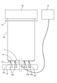
本実験例は、図2に示すように、パルスジェネレータ50に被覆電線(「電線」の一例)60をループ状に接続している。被覆電線60のパルスジェネレータ50側の端部には、パルスジェネレータ50側から被覆電線60側にパルスが漏れるのを防ぐために、遮蔽板70を設置している。
次に、実験例を挙げて本実施形態をさらに詳細に説明する。
本実験例は、図2に示すように、パルスジェネレータ50に被覆電線(「電線」の一例)60をループ状に接続している。被覆電線60のパルスジェネレータ50側の端部には、パルスジェネレータ50側から被覆電線60側にパルスが漏れるのを防ぐために、遮蔽板70を設置している。
シールド部材110の柔軟導体(「シールド導体」の一例)112は、ループ状に配置された被覆電線60の一部に巻き付けて取り付けられている。被覆電線60に取り付けられた柔軟導体112には、グランドフレームG1に接続されたグランド導体120が左右方向に等間隔に接続されている。柔軟導体112に接続されたグランド導体120には、補助シールド導体130が巻き付けられている。そして、グランド導体120に取り付けられた補助シールド導体130の柔軟導体112側の端部には、グランドフレームG1に接続された補助グランド導体135が接続されている。
つまり、柔軟導体112が巻き付けられた部分を、被覆電線Wの干渉部W1の代わりとしてシールド部材110の放射エミッション低減効果を測定する。
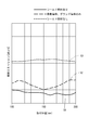
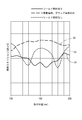
図3から図6のグラフは、パルスジェネレータ50から出力されるパルスの周波数を変更した場合の被覆電線60の放射エミッションを示している。また、それぞれの図における被覆電線60の放射エミッションの測定におけるパルスの周波数は、図3が75MHz、図4が125MHz、図5が225MHz、図6が275MHzである。放射エミッションの測定は、図2に示すように、スペクトルアナライザAに接続されたプローブPを柔軟導体112に対して10cm間隔で接触させ、接触させた時の放射エミッションを測定している。図3から図6のグラフでは、X軸が柔軟導体112のパルスジェネレータ50からの距離[cm]を示しており、Y軸が放射エミッションの強度[dBμV]を示している。
また、各グラフでは、シールド部材110が取り付けられた被覆電線60の放射エミッションをS1、柔軟導体112とグランド導体120のみ(補助シールド導体および補助グランド導体なし)が取り付けられた被覆電線60の放射エミッションをS2、何も取り付けられていない被覆電線60の放射エミッションをS3として示している。
ここで、各グラフのS1からS3を比較すると、本実施形態のシールド部材110を取り付けた被覆電線(S1)は、柔軟導体112とグランド導体120のみを取り付けた被覆電線(S2)や何も取り付けられていない被覆電線(S3)に比べて、放射エミッションが低減していることが確認できる。
つまり、本実施形態によると、被覆電線60において生じる電気的ノイズをグランドフレームG1に流すことに加えて、グランド導体120に生じる電気的ノイズをグランドフレームG1に流すことにより、被覆電線60の放射エミッション低減効果を向上させることができるようになっている。
ところで、被覆電線60において生じる電気的ノイズが200MHz帯付近になると、図5および図6に示すように、被覆電線60に柔軟導体112とグランド導体120のみを取り付けただけでは放射エミッション低減効果が低下してしまう。
ところが、本実施形態のシールド部材110を取り付けた場合には、グランド導体に生じる電気的ノイズをグランド電位に流す構成となっているから、図5および図6に示すように、電気的ノイズが200MHz帯付近になった場合においても、放射エミッション低減効果を向上した状態に維持することができる。
すわなち、本実施形態のシールド部材110によると、少なくとも75MHzから275MHzの幅広い周波数帯の電気的ノイズを低減させる効果(放射エミッション低減効果)を向上させることができる。なお、図5および図6において、シールド部材110が取り付けられていない被覆電線60の放射エミッションの値が小さい箇所は、入力波の節と反射波の節とが重なることによる定在波の影響によるものである。
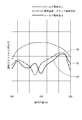
図7に示されるグラフは、パルスジェネレータ50から出力されるパルスの周波数が75MHzの場合の被覆電線60の放射エミッションを示しており、図8に示されるグラフは、パルスの周波数が125MHzの場合の被覆電線60の放射エミッションを示している。
また、各グラフでは、シールド部材110が取り付けられた被覆電線60の放射エミッションをS4、柔軟導体112とグランド導体120のみ(補助シールド導体および補助グランド導体なし)が取り付けられた被覆電線60の放射エミッションをS5、何も取り付けられていない被覆電線60の放射エミッションをS6として示している。
被覆電線60に柔軟導体112とグランド導体120のみ(補助シールド導体および補助グランド導体なし)が取り付けられたものについては、グランド導体120は、柔軟導体112に対して、20cm間隔で等間隔に接続されている。
被覆電線60にシールド部材110が取り付けられたものについては、グランド導体120は柔軟導体112に対して50cm間隔で等間隔に接続されている。
各グラフのS4からS6を比較すると、本実施形態のシールド部材110を取り付けた被覆電線(S4)は、柔軟導体112とグランド導体120のみを取り付けた被覆電線(S5)や何も取り付けられていない被覆電線(S6)に比べて、放射エミッションが低減していることが確認できる。
さらに、S4とS5とを比較すると、シールド部材110を被覆電線60に取り付けた場合(S4)には、グランド導体120の間隔が50cmであっても、被覆電線60に柔軟導体112とグランド導体120のみを20cm間隔で取り付けた場合(S5)とほぼ同じ程度の放射エミッション低減効果を得ることができる。つまり、本開示にかかるシールド部材110を用いることにより、被覆電線60に柔軟導体112とグランド導体120のみを取り付けた場合に比べて少ない個数のグランド導体120で、効率的に放射エミッション低減効果を得ることができる。
<他の実施形態>
本明細書で開示される技術は上記記述及び図面によって説明した実施形態に限定されるものではなく、例えば次のような種々の態様も含まれる。
(1)上記実施形態では、被覆電線Wの干渉部W1が信号線Tの近傍に配された構成とした。しかしながら、これに限らず、電線の干渉部が電子機器や蓄電装置などの近傍に配される場合に本明細書で開示した技術を適用してもよい。
本明細書で開示される技術は上記記述及び図面によって説明した実施形態に限定されるものではなく、例えば次のような種々の態様も含まれる。
(1)上記実施形態では、被覆電線Wの干渉部W1が信号線Tの近傍に配された構成とした。しかしながら、これに限らず、電線の干渉部が電子機器や蓄電装置などの近傍に配される場合に本明細書で開示した技術を適用してもよい。
(2)上記実施形態では、干渉部W1に柔軟導体12を巻き付ける構成にした。しかしながら、これに限らず、干渉部の外周に隙間を隔てて柔軟導体を配置する構成にしてもよい。
(3)上記実施形態では、グランド導体20において芯線を露出させた部分に端子26を接続することによってグランド接続部24を構成した。しかしながら、これに限らず、導体接続部と同様に、グランド導体の芯線を露出させることによってグランド接続部を構成し、芯線によって構成されたグランド接続部を半田などでボディアースに直接固定してもよい。
(3)上記実施形態では、グランド導体20において芯線を露出させた部分に端子26を接続することによってグランド接続部24を構成した。しかしながら、これに限らず、導体接続部と同様に、グランド導体の芯線を露出させることによってグランド接続部を構成し、芯線によって構成されたグランド接続部を半田などでボディアースに直接固定してもよい。
(4)上記実施形態では、1本の被覆電線Wにシールド部材10を取り付ける構成にした。しかしながら、これに限らず、複数本の被覆電線にシールド部材を取り付ける構成にしてもよい。
(5)上記実施形態では、補助グランド導体35には何も取り付けられていない構成にした。しかしながら、これに限らず、補助グランド導体に対して、グランド電位に接続された柔軟導体を更に取り付けて、補助グランド導体の電気的ノイズをグランド電位に流す構成にしてもよい。
(5)上記実施形態では、補助グランド導体35には何も取り付けられていない構成にした。しかしながら、これに限らず、補助グランド導体に対して、グランド電位に接続された柔軟導体を更に取り付けて、補助グランド導体の電気的ノイズをグランド電位に流す構成にしてもよい。
10,110:シールド部材
12,112:柔軟導体(「シールド導体」の一例)
20,120:グランド導体
22:導体接続部
24:グランド接続部
26:端子
30,130:補助シールド導体
35,135:補助グランド導体
36:端子
50:パルスジェネレータ
70:遮蔽板
A:スペクトルアナライザ
G1:グランドフレーム
G:ボディアース
P:プローブ
T:信号線(「対象物」の一例)
W,60:被覆電線(「電線」の一例)
W1:干渉部
12,112:柔軟導体(「シールド導体」の一例)
20,120:グランド導体
22:導体接続部
24:グランド接続部
26:端子
30,130:補助シールド導体
35,135:補助グランド導体
36:端子
50:パルスジェネレータ
70:遮蔽板
A:スペクトルアナライザ
G1:グランドフレーム
G:ボディアース
P:プローブ
T:信号線(「対象物」の一例)
W,60:被覆電線(「電線」の一例)
W1:干渉部
Claims (4)
- 少なくとも1本の電線の外周を覆う導電性を有するシールド導体と、
前記シールド導体とグランド電位とを電気的に接続する少なくとも1本のグランド導体と、
前記グランド導体の外周を覆う補助シールド導体と、
前記補助シールド導体とグランド電位とを電気的に接続する補助グランド導体と、を備えるシールド部材。 - 前記シールド導体は、導電性を有し、少なくとも1本の電線の外周を覆う柔軟なシート状に形成されている請求項1に記載のシールド部材。
- 前記シールド導体は、電気的ノイズの影響を受けやすい対象物の近傍に配置された前記電線に巻き付けて取り付けられる請求項2に記載のシールド部材。
- 前記グランド導体は前記シールド導体に等間隔に接続されている請求項1から請求項3のいずれか1項に記載のシールド部材。
Priority Applications (2)
| Application Number | Priority Date | Filing Date | Title |
|---|---|---|---|
| CN202080011603.5A CN113383471A (zh) | 2019-02-07 | 2020-01-22 | 屏蔽构件 |
| US17/425,233 US11464144B2 (en) | 2019-02-07 | 2020-01-22 | Shield member |
Applications Claiming Priority (4)
| Application Number | Priority Date | Filing Date | Title |
|---|---|---|---|
| JP2019-020315 | 2019-02-07 | ||
| JP2019020315 | 2019-02-07 | ||
| JP2019177510A JP2020129651A (ja) | 2019-02-07 | 2019-09-27 | シールド部材 |
| JP2019-177510 | 2019-09-27 |
Publications (1)
| Publication Number | Publication Date |
|---|---|
| WO2020162173A1 true WO2020162173A1 (ja) | 2020-08-13 |
Family
ID=71947137
Family Applications (1)
| Application Number | Title | Priority Date | Filing Date |
|---|---|---|---|
| PCT/JP2020/002078 Ceased WO2020162173A1 (ja) | 2019-02-07 | 2020-01-22 | シールド部材 |
Country Status (2)
| Country | Link |
|---|---|
| US (1) | US11464144B2 (ja) |
| WO (1) | WO2020162173A1 (ja) |
Citations (4)
| Publication number | Priority date | Publication date | Assignee | Title |
|---|---|---|---|---|
| JPS5874360U (ja) * | 1981-11-13 | 1983-05-19 | 株式会社日立製作所 | シ−ルドジヤンパ−線 |
| JPH0879190A (ja) * | 1994-09-08 | 1996-03-22 | Fujitsu Ltd | 平衡伝送線路の電磁妨害防止装置 |
| WO2014148446A1 (ja) * | 2013-03-19 | 2014-09-25 | 矢崎総業株式会社 | 電線のシールド構造 |
| WO2017006497A1 (ja) * | 2015-07-09 | 2017-01-12 | 株式会社オートネットワーク技術研究所 | ノイズフィルタ付き導電路 |
Family Cites Families (11)
| Publication number | Priority date | Publication date | Assignee | Title |
|---|---|---|---|---|
| US6639148B2 (en) * | 2001-06-20 | 2003-10-28 | Federal-Mogul Systems Protection Group, Inc. | Extendible drain members for grounding RFI/EMI shielding |
| JP2013030722A (ja) * | 2011-06-22 | 2013-02-07 | Seiko Epson Corp | 接続構造および接続方法 |
| JP5772698B2 (ja) | 2012-04-18 | 2015-09-02 | 株式会社オートネットワーク技術研究所 | 電磁シールド具及びワイヤハーネス |
| JP6077865B2 (ja) * | 2013-01-23 | 2017-02-08 | 矢崎総業株式会社 | ノイズ低減シールドケーブル |
| JP5971563B2 (ja) * | 2013-11-29 | 2016-08-17 | 住友電装株式会社 | 電線のシールド構造 |
| JP2016048713A (ja) * | 2014-08-27 | 2016-04-07 | 住友電装株式会社 | ワイヤーハーネスのシールド構造 |
| DE102014219645B4 (de) * | 2014-09-29 | 2020-12-24 | Bayerische Motoren Werke Aktiengesellschaft | Elektrische Verbindungseinrichtung zum Übertragen von elektrischer Energie und/oder Daten, Bordnetz und Kraftfahrzeug |
| JP6265157B2 (ja) * | 2015-03-26 | 2018-01-24 | トヨタ自動車株式会社 | 通信システム |
| JP6418095B2 (ja) * | 2015-07-21 | 2018-11-07 | 株式会社オートネットワーク技術研究所 | シールド導電路 |
| JP6208394B1 (ja) * | 2017-05-23 | 2017-10-04 | 清二 加川 | 電磁波吸収フィルタ |
| JP2019021824A (ja) * | 2017-07-20 | 2019-02-07 | 株式会社オートネットワーク技術研究所 | ケーブルの接続構造 |
-
2020
- 2020-01-22 WO PCT/JP2020/002078 patent/WO2020162173A1/ja not_active Ceased
- 2020-01-22 US US17/425,233 patent/US11464144B2/en active Active
Patent Citations (4)
| Publication number | Priority date | Publication date | Assignee | Title |
|---|---|---|---|---|
| JPS5874360U (ja) * | 1981-11-13 | 1983-05-19 | 株式会社日立製作所 | シ−ルドジヤンパ−線 |
| JPH0879190A (ja) * | 1994-09-08 | 1996-03-22 | Fujitsu Ltd | 平衡伝送線路の電磁妨害防止装置 |
| WO2014148446A1 (ja) * | 2013-03-19 | 2014-09-25 | 矢崎総業株式会社 | 電線のシールド構造 |
| WO2017006497A1 (ja) * | 2015-07-09 | 2017-01-12 | 株式会社オートネットワーク技術研究所 | ノイズフィルタ付き導電路 |
Also Published As
| Publication number | Publication date |
|---|---|
| US11464144B2 (en) | 2022-10-04 |
| US20220095497A1 (en) | 2022-03-24 |
Similar Documents
| Publication | Publication Date | Title |
|---|---|---|
| JP6135585B2 (ja) | 配線部材 | |
| CN100361358C (zh) | 电子设备间的连接方法和连接电缆 | |
| US8822846B2 (en) | Cable holding structure | |
| JP5579215B2 (ja) | ワイヤーハーネスおよびワイヤーハーネスのシールド構造 | |
| JP2010282773A (ja) | 車両用ワイヤハーネス | |
| EP1605544A1 (en) | Antenna device and antenna device manufacturing method | |
| JPH11260160A (ja) | 放射ノイズ抑制用磁性複合テープ及びこの複合テープを用いた放射ノイズ抑制部品 | |
| JP6180141B2 (ja) | 電線のシールド構造 | |
| WO2020162173A1 (ja) | シールド部材 | |
| JP2010126043A (ja) | 車載電装品の電気的接続構造 | |
| JP3302069B2 (ja) | 超音波プローブ | |
| JP2020129651A (ja) | シールド部材 | |
| JP3232719U (ja) | 電磁干渉抑制装置 | |
| WO2020066514A1 (ja) | シールド部材 | |
| US20250189571A1 (en) | Electromagnetic wave detection device | |
| JP3029198B1 (ja) | 接地用電線 | |
| JP6812205B2 (ja) | ワイヤーハーネス | |
| CN212519866U (zh) | 电磁干扰抑制装置 | |
| JPH11337839A (ja) | 内視鏡ケーブル装置 | |
| JP6405480B1 (ja) | ノイズフィルター | |
| JP2017147307A (ja) | ノイズ除去装置及びこれを用いたケーブルコネクタ並びにノイズ除去方法 | |
| JP2016181657A (ja) | 防水性シールド構造 | |
| US20240300423A1 (en) | Cable attachment structure | |
| JP4667292B2 (ja) | 電子機器用シールドケース | |
| JP7205078B2 (ja) | 車載用ワイヤハーネス |
Legal Events
| Date | Code | Title | Description |
|---|---|---|---|
| 121 | Ep: the epo has been informed by wipo that ep was designated in this application |
Ref document number: 20752278 Country of ref document: EP Kind code of ref document: A1 |
|
| NENP | Non-entry into the national phase |
Ref country code: DE |
|
| 122 | Ep: pct application non-entry in european phase |
Ref document number: 20752278 Country of ref document: EP Kind code of ref document: A1 |