WO2020162148A1 - ベルト式無段変速機 - Google Patents
ベルト式無段変速機 Download PDFInfo
- Publication number
- WO2020162148A1 WO2020162148A1 PCT/JP2020/001687 JP2020001687W WO2020162148A1 WO 2020162148 A1 WO2020162148 A1 WO 2020162148A1 JP 2020001687 W JP2020001687 W JP 2020001687W WO 2020162148 A1 WO2020162148 A1 WO 2020162148A1
- Authority
- WO
- WIPO (PCT)
- Prior art keywords
- pulley
- belt
- primary
- continuously variable
- variable transmission
- Prior art date
- Legal status (The legal status is an assumption and is not a legal conclusion. Google has not performed a legal analysis and makes no representation as to the accuracy of the status listed.)
- Ceased
Links
Images


Classifications
-
- F—MECHANICAL ENGINEERING; LIGHTING; HEATING; WEAPONS; BLASTING
- F16—ENGINEERING ELEMENTS AND UNITS; GENERAL MEASURES FOR PRODUCING AND MAINTAINING EFFECTIVE FUNCTIONING OF MACHINES OR INSTALLATIONS; THERMAL INSULATION IN GENERAL
- F16H—GEARING
- F16H61/00—Control functions within control units of change-speed- or reversing-gearings for conveying rotary motion ; Control of exclusively fluid gearing, friction gearing, gearings with endless flexible members or other particular types of gearing
- F16H61/12—Detecting malfunction or potential malfunction, e.g. fail safe ; Circumventing or fixing failures
-
- F—MECHANICAL ENGINEERING; LIGHTING; HEATING; WEAPONS; BLASTING
- F16—ENGINEERING ELEMENTS AND UNITS; GENERAL MEASURES FOR PRODUCING AND MAINTAINING EFFECTIVE FUNCTIONING OF MACHINES OR INSTALLATIONS; THERMAL INSULATION IN GENERAL
- F16H—GEARING
- F16H61/00—Control functions within control units of change-speed- or reversing-gearings for conveying rotary motion ; Control of exclusively fluid gearing, friction gearing, gearings with endless flexible members or other particular types of gearing
- F16H61/16—Inhibiting or initiating shift during unfavourable conditions , e.g. preventing forward-reverse shift at high vehicle speed, preventing engine overspeed
Definitions
- the present invention relates to a belt type continuously variable transmission capable of steplessly changing a gear ratio when transmitting power between pulleys by a belt.
- Patent Document 1 in shifting pressure control of a belt type continuously variable transmission, a pulley ratio is calculated every predetermined time based on the number of revolutions of a primary pulley and a secondary pulley, and a moving average value of the pulley ratio is calculated. .. Then, a technique of calculating the difference between the moving average value and the pulley ratio calculated every predetermined time, and determining that the steady belt slip has occurred when the calculated difference is larger than the first predetermined value. Is disclosed.
- the present invention has been made in view of the above problems, and an object thereof is to provide a belt-type continuously variable transmission capable of detecting steady belt slip at an early stage.
- a belt type continuously variable transmission includes a primary pulley, a secondary pulley, and a belt wound around both pulleys, and a pulley pressing force is supplied to the primary pulley.
- a belt type continuously variable transmission determined by the pressure and the secondary pressure supplied to the secondary pulley, When the deviation between the target pulley ratio set based on the running state and the actual pulley ratio calculated from the rotation speeds of the primary pulley and the secondary pulley continues for a predetermined time or more for a predetermined time, the secondary pressure When the actual pulley ratio shifts to the high side as the secondary pressure increases, it is determined that belt slip has occurred.
- the measured lower limit of the primary pressure is set to a high value, so belt slip can be suppressed.
- FIG. 1 is a diagram showing a schematic configuration of a continuously variable transmission according to a first embodiment.
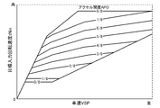
- 3 is a shift map according to the first embodiment.
- 5 is a flowchart showing a steady slip determination process of the first embodiment. 5 is a time chart showing the relationship between the pulley ratio and the primary pressure and the secondary pressure when a steady slip occurs in the first embodiment.
- FIG. 1 is a diagram showing a schematic configuration of a continuously variable transmission (hereinafter, referred to as “CVT”) 1 according to the first embodiment.
- CVT continuously variable transmission
- the primary pulley 2 and the secondary pulley 3 are arranged so that their grooves are aligned, and a belt 4 is stretched over the grooves of these pulleys 2 and 3.
- An engine 5 is arranged coaxially with the primary pulley 2, and a torque converter 6 and a forward/reverse switching mechanism 7 are provided between the engine 5 and the primary pulley 2 in this order from the engine 5 side.
- the torque converter 6 includes a pump impeller 6a connected to the output shaft of the engine 5, a turbine runner 6b connected to the input shaft of the forward/reverse switching mechanism 7, a stator 6c, and a lockup clutch 6d.
- the forward/reverse switching mechanism 7 has a double pinion planetary gear set 7a as a main component, its sun gear is connected to the turbine runner 6b of the torque converter 6, and the carrier is connected to the primary pulley 2.
- the forward/reverse switching mechanism 7 further includes a starting clutch 7b that directly connects the sun gear of the double pinion planetary gear set 7a and the carrier, and a reverse brake 7c that fixes the ring gear.
- the start clutch 7b When the start clutch 7b is engaged, the input rotation from the engine 5 via the torque converter 6 is transmitted to the primary pulley 2 as it is, and when the reverse brake 7c is engaged, the input rotation from the engine 5 via the torque converter 6 is reversed. , To the primary pulley 2.
- one of the conical plates forming the grooves of the primary pulley 2 and the secondary pulley 3 is a fixed conical plate. 2a and 3a, and the other conical plates 2b and 3b are movable conical plates that can be displaced in the axial direction.
- the movable conical plates 2b and 3b are urged toward the fixed conical plates 2a and 3a by supplying the primary pressure Ppri and the secondary pressure Psec created by using the line pressure as a source pressure to the primary pulley chamber 2c and the secondary pulley chamber 3c.
- the belt 4 is frictionally engaged with the conical plate to transmit power between the primary pulley 2 and the secondary pulley 3.
- the speed change is performed by changing the widths of the grooves of the pulleys 2 and 3 by the pressure difference between the primary pressure Ppri and the secondary pressure Psec, and continuously changing the winding arc diameter of the belt 4 around the pulleys 2 and 3. ..
- the primary pressure Ppri and the secondary pressure Psec are controlled by the shift control hydraulic circuit 11 together with the hydraulic pressures supplied to the starting clutch 7b that is engaged when selecting the forward travel range and the reverse brake 7c that is engaged when selecting the reverse travel range.
- the shift control hydraulic circuit 11 performs control in response to a signal from the transmission controller 12.
- the transmission controller 12 includes a signal from the primary rotation speed sensor 13 that detects the primary rotation speed Npri of the primary pulley 2 of the CVT 1 and a secondary rotation speed Nsec of the secondary pulley 3 of the CVT 1 (where Nsec is the final reduction ratio or the tire speed).
- a vehicle speed VSP can be calculated using specifications such as diameter
- a signal from 18 and a signal relating to the operating state of the engine 5 are input from an engine controller 19 that controls the engine 5.
- the transmission controller 12 refers to the shift map shown in FIG. 2, sets the target input rotation speed tNin according to the running state, and controls so that the primary rotation speed Npri follows the target input rotation speed tNin.
- setting the target input rotation speed tNin is synonymous with setting the target pulley ratio. This is because the pulley ratio is a value obtained by dividing the secondary rotation speed Nsec by the primary rotation speed Npri, and the secondary rotation speed Nsec is a value that is uniquely determined by the vehicle speed VSP. Further, when controlling the pulley ratio, the target primary pressure Ppri* and the target secondary pressure Psec* are obtained so that the pulley pressing force required to transmit the input torque of the CVT 1 determined by the engine torque and the torque converter torque ratio is obtained.
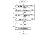
- FIG. 3 is a flowchart showing the steady slip determination process of the first embodiment.
- step S1 it is determined whether or not a precondition for starting the steady slip determination process is satisfied. If it is determined that the precondition is satisfied, the process proceeds to step S2, otherwise the precondition is satisfied. Repeat this step until you do.
- the precondition indicates, for example, that no other abnormality has occurred in the vehicle and various driving conditions are satisfied.
- step S2 it is determined whether or not the first condition of steady slip is satisfied. If the first condition is satisfied, the process proceeds to step S3, and otherwise returns to step S1.
- the steady-state first slip condition is that the pulley ratio is equal to or higher than a predetermined pulley ratio, the actual pulley ratio is deviated from the target pulley ratio on the High side for a predetermined time, and the primary pressure Ppri is maintained. And that the secondary pressure Psec follows the target pressure.
- the predetermined pulley ratio is a pulley ratio indicating that the pulley ratio is on the High side instead of the Low side, and is, for example, 0.4 or more. The reason for setting the predetermined pulley ratio will be described later.
- the actual pulley ratio being shifted to the High side means that the target pulley ratio and the actual pulley ratio are deviated from each other by a value or more indicating that the deviating is surely taking into consideration the detection error of the sensor or the like.
- following the target pressure means that the difference between each pulley pressure and the target pressure is less than a predetermined pressure in consideration of a detection error of a sensor or the like.
- FIG. 4 is a time chart showing the relationship between the pulley ratio and the primary pressure and the secondary pressure when a steady slip occurs in the first embodiment.
- the actual pulley ratio is deviated to the High side from the target pulley ratio, and it is in the state of continuing for a predetermined time.
- the cause of the slip between the secondary pulley 3 and the belt 4 is that the secondary pressure Psec is insufficient or that the friction coefficient (hereinafter referred to as ⁇ ) at the contact surface is reduced. Conceivable. If the first condition is satisfied, even if the secondary pressure Psec is output as scheduled, the pulley ratio is shifted to the High side, and therefore ⁇ at the contact surface may be reduced.
- step S3 the second condition shown in step S3 is set.
- the reason why the predetermined condition is set to be equal to or higher than the predetermined pulley ratio is that there is no possibility of contact with the shaft portion of the secondary pulley 3 if it is lower than the predetermined pulley ratio, and higher than the predetermined pulley ratio. It was decided to monitor steady slip at.
- step S3 it is determined whether or not the second condition of steady slip is satisfied, and if the second condition is satisfied, the process proceeds to step S4, and otherwise returns to step S1.
- the second steady-state slip condition is that the actual pulley ratio shifts to the High side when the secondary pressure Psec is increased by a preset predetermined pressure.
- a steady slip has not occurred and only the secondary pressure Psec is increased as shown in the second condition of the time chart of FIG.
- the balance thrust ratio was maintained between the primary pressure Ppri and the secondary pressure Psec. If only the secondary pressure Psec increases, the balance thrust ratio collapses and shifts to the low side.
- step S4 it is determined whether or not the satisfaction of the second condition of the steady slip is detected a plurality of times. If it is detected a plurality of times, the steady slip is determined and the process proceeds to step S5. Otherwise, the process returns to step S1 and repeats. Perform the flow. In step S5, a lighting command is output to the lamp 20 to notify the driver of the abnormality.
- step S6 the use of the pulley ratio on the High side of the pulley ratio when the steady slip is confirmed is enforced.
- the pulley ratio is set to a lower side than the pulley ratio when the steady slip is determined. That is, since the ⁇ of the pulley ratio when the steady slip is confirmed is decreased, the continuous use of the pulley may increase the problems that occur in the belt type continuously variable transmission.
- the pulley ratio on the Low side of the pulley ratio region where ⁇ decreases can be used as usual. Therefore, by restricting the use as in the first embodiment, the traveling performance can be secured as compared with the limp home traveling in which the traveling performance is restricted in all the pulley ratio regions.
- a primary pulley 2, a secondary pulley 3, and a belt 4 wound around both pulleys 2 and 3 are provided, and the pulley pressing force is supplied to the primary pulley 2 and the secondary pulley 3.
- the deviation between the target pulley ratio set based on the running state and the actual pulley ratio calculated from the rotation speeds of the primary pulley 2 and the secondary pulley 3 is a predetermined value.
- the secondary pressure Psec is increased, and when the actual pulley ratio shifts to the high side with the increase of the secondary pressure Psec, steady slip (belt slip) occurs. To judge. Therefore, it is possible to eliminate the state where the target pulley ratio and the actual pulley ratio deviate from each other due to factors other than the steady slip, and it is not necessary to judge the state where they deviate from each other over time. Can be detected.
Landscapes
- Engineering & Computer Science (AREA)
- General Engineering & Computer Science (AREA)
- Mechanical Engineering (AREA)
- Control Of Transmission Device (AREA)
Abstract
本発明に係るベルト式無段変速機(CVT)は、プライマリプーリ(2)と、セカンダリプーリ(3)と、両プーリに巻回されたベルト(4)と、を備え、プーリ押し付け力がプライマリプーリ(2)に供給されるプライマリ圧(Ppri)及びセカンダリプーリ(3)に供給されるセカンダリ圧(Psec)によって決まるベルト式無段変速機である。そして、このベルト式無段変速機(CVT)では、走行状態に基づいて設定された目標プーリ比と、プライマリプーリ(2)及びセカンダリプーリ(3)の回転数から算出された実プーリ比との乖離が所定値以上の状態が所定時間継続したときは、セカンダリ圧(Psec)を上昇させ、該セカンダリ圧(Psec)の上昇に伴って前記実プーリ比がハイ側にシフトしたときは、ベルト滑りが発生していると判断することとした。
Description
本発明は、プーリ間の動力をベルトにより伝達する際の変速比を無段階に変更可能なベルト式無段変速機に関する。
従来、特許文献1には、ベルト式無段変速機の変速圧力制御において、プライマリプーリとセカンダリプーリの回転数に基づいてプーリ比を所定時間毎に算出し、プーリ比の移動平均値を算出する。そして、移動平均値と所定時間毎に算出されるプーリ比との差を算出し、算出された差が第1の所定値より大きいときは、定常的なベルト滑りが生じていると判定する技術が開示されている。
しかしながら、定常的なベルト滑りの検知に時間がかかると、ベルトやプーリの耐久性の低下を招くおそれがあり、また、検知した後にベルトの破損等を回避するために、走行性能を制限した変速制御(いわゆるリンプホーム走行)を実施すると、走行性能を十分に確保できないという問題があった。
本発明は、上記課題に着目してなされたもので、早期に定常的なベルト滑りを検知可能なベルト式無段変速機を提供することを目的とする。
上記目的を達成するため、本発明のベルト式無段変速機では、プライマリプーリと、セカンダリプーリと、両プーリに巻回されたベルトとを備え、プーリ押し付け力が前記プライマリプーリに供給されるプライマリ圧及び前記セカンダリプーリに供給されるセカンダリ圧によって決まるベルト式無段変速機であって、
走行状態に基づいて設定された目標プーリ比と、前記プライマリプーリ及び前記セカンダリプーリの回転数から算出された実プーリ比との乖離が所定値以上の状態が所定時間継続したときは、前記セカンダリ圧を上昇させ、該セカンダリ圧の上昇に伴って前記実プーリ比がハイ側にシフトしたときは、ベルト滑りが発生していると判断することとした。
走行状態に基づいて設定された目標プーリ比と、前記プライマリプーリ及び前記セカンダリプーリの回転数から算出された実プーリ比との乖離が所定値以上の状態が所定時間継続したときは、前記セカンダリ圧を上昇させ、該セカンダリ圧の上昇に伴って前記実プーリ比がハイ側にシフトしたときは、ベルト滑りが発生していると判断することとした。
よって、タイヤがロック傾向となったとしても、プライマリ圧の実測下限値が高く設定されるため、ベルト滑りを抑制できる。
〔実施形態1〕
図1は、実施形態1の無段変速機(以下、「CVT」という。)1の概略構成を示す図である。プライマリプーリ2及びセカンダリプーリ3が両者の溝が整列するよう配置され、これらプーリ2、3の溝にはベルト4が掛け渡されている。プライマリプーリ2と同軸にエンジン5が配置され、エンジン5とプライマリプーリ2の間には、エンジン5の側から順に、トルクコンバータ6、前後進切換え機構7が設けられている。
図1は、実施形態1の無段変速機(以下、「CVT」という。)1の概略構成を示す図である。プライマリプーリ2及びセカンダリプーリ3が両者の溝が整列するよう配置され、これらプーリ2、3の溝にはベルト4が掛け渡されている。プライマリプーリ2と同軸にエンジン5が配置され、エンジン5とプライマリプーリ2の間には、エンジン5の側から順に、トルクコンバータ6、前後進切換え機構7が設けられている。
トルクコンバータ6は、エンジン5の出力軸に連結されるポンプインペラ6a、前後進切換え機構7の入力軸に連結されるタービンランナ6b、ステータ6c及びロックアップクラッチ6dを備える。
前後進切換え機構7は、ダブルピニオン遊星歯車組7aを主たる構成要素とし、そのサンギヤはトルクコンバータ6のタービンランナ6bに結合され、キャリアはプライマリプーリ2に結合される。前後進切換え機構7は、さらに、ダブルピニオン遊星歯車組7aのサンギヤ及びキャリア間を直結する発進クラッチ7b、及びリングギヤを固定する後進ブレーキ7cを備える。そして、発進クラッチ7bの締結時には、エンジン5からトルクコンバータ6を経由した入力回転がそのままプライマリプーリ2に伝達され、後進ブレーキ7cの締結時には、エンジン5からトルクコンバータ6を経由した入力回転が逆転され、プライマリプーリ2へと伝達される。
プライマリプーリ2の回転はベルト4を介してセカンダリプーリ3に伝達され、セカンダリプーリ3の回転は、出力軸8、歯車組9及びディファレンシャルギヤ装置10を経て図示しない駆動輪へと伝達される。上記の動力伝達中にプライマリプーリ2及びセカンダリプーリ3間のプーリ比(変速比)を変更可能にするために、プライマリプーリ2及びセカンダリプーリ3の溝を形成する円錐板のうち一方を固定円錐板2a、3aとし、他方の円錐板2b、3bを軸線方向へ変位可能な可動円錐板としている。これら可動円錐板2b、3bは、ライン圧を元圧として作り出したプライマリ圧Ppri及びセカンダリ圧Psecをプライマリプーリ室2c及びセカンダリプーリ室3cに供給することにより固定円錐板2a、3aに向けて付勢され、これによりベルト4を円錐板に摩擦係合させてプライマリプーリ2及びセカンダリプーリ3間での動力伝達が行われる。
変速は、プライマリ圧Ppri及びセカンダリ圧Psec間の差圧により両プーリ2、3の溝の幅を変化させ、プーリ2、3に対するベルト4の巻き掛け円弧径を連続的に変化させることによって行われる。プライマリ圧Ppri及びセカンダリ圧Psecは、前進走行レンジの選択時に締結する発進クラッチ7b及び後進走行レンジの選択時に締結する後進ブレーキ7cへの供給油圧と共に変速制御油圧回路11によって制御される。変速制御油圧回路11は変速機コントローラ12からの信号に応答して制御を行う。
変速機コントローラ12には、CVT1のプライマリプーリ2のプライマリ回転数Npriを検出するプライマリ回転数センサ13からの信号と、CVT1のセカンダリプーリ3のセカンダリ回転数Nsec(尚、Nsecに終減速比やタイヤ径といった諸元を用いて車速VSPを算出可能)を検出するセカンダリ回転数センサ14からの信号と、プライマリ圧Ppriを検出するプライマリ圧センサ15pからの信号と、セカンダリ圧Psecを検出するセカンダリ圧センサ15sからの信号と、アクセル開度APOを検出するアクセル開度センサ16からの信号と、セレクトレバー位置を検出するインヒビタスイッチ17からの選択レンジ信号と、ブレーキペダルの踏み込みの有無を検出するブレーキスイッチ18からの信号と、エンジン5を制御するエンジンコントローラ19からのエンジン5の運転状態(エンジン回転速度Ne、エンジントルク、燃料噴時間、冷却水温TMPe等)に関する信号とが入力される。
変速機コントローラ12は、図2に示す変速マップを参照し、走行状態に応じて目標入力回転速度tNinを設定し、プライマリ回転数Npriが目標入力回転速度tNinに追従するように制御する。尚、目標入力回転速度tNinを設定することは、目標プーリ比を設定することと同義である。プーリ比は、セカンダリ回転数Nsecをプライマリ回転数Npriで除した値であり、セカンダリ回転数Nsecは、車速VSPによって一義的に決定される値だからである。また、プーリ比を制御する際には、エンジントルク及びトルクコンバータトルク比によって決まるCVT1の入力トルクを伝達するのに必要なプーリ押し付け力が得られるように、目標プライマリ圧Ppri*及び目標セカンダリ圧Psec*を設定し、実プライマリ圧Ppri及び実セカンダリ圧Psecが目標圧に追従するようにフィードバック制御する。また、異常を表す所定条件が成立したときは、運転者に異常を報知可能なランプ20に対して点灯指令を出力する。
図3は、実施形態1の定常スリップ判定処理を表すフローチャートである。
ステップS1では、定常スリップ判定処理を開始するための前提条件が成立しているか否かを判断し、前提条件が成立していると判断したときはステップS2に進み、それ以外は前提条件が成立するまで本ステップを繰り返す。ここで、前提条件とは、例えば、車両に他の異常が発生しておらず、各種運転条件が成立していることを表す。
ステップS1では、定常スリップ判定処理を開始するための前提条件が成立しているか否かを判断し、前提条件が成立していると判断したときはステップS2に進み、それ以外は前提条件が成立するまで本ステップを繰り返す。ここで、前提条件とは、例えば、車両に他の異常が発生しておらず、各種運転条件が成立していることを表す。
ステップS2では、定常スリップ第1条件が成立したか否かを判断し、第1条件が成立しているときにはステップS3へ進み、それ以外はステップS1に戻る。ここで、定常スリップ第1条件とは、プーリ比が所定プーリ比以上であって、目標プーリ比に対して実プーリ比がHigh側ずれた状態が所定時間継続しており、かつ、プライマリ圧Ppri及びセカンダリ圧Psecが目標圧に追従していることである。所定プーリ比とは、プーリ比がLow側ではなく、High側であることを表すプーリ比であり、例えば0.4以上である。所定プーリ比を設定した理由については後述する。また、実プーリ比がHigh側にずれるとは、目標プーリ比と実プーリ比とがセンサ等の検出誤差を考慮した上で確実にずれが生じていることを表す値以上乖離している状態であり、目標圧に追従とは、センサ等の検出誤差を考慮して各プーリ圧と目標圧との差が所定圧未満であることを表す。
図4は、実施形態1で定常スリップが生じた場合におけるプーリ比と、プライマリ圧及びセカンダリ圧の関係を表すタイムチャートである。第1条件の領域において、実プーリ比が目標プーリ比よりもHigh側にずれており、それが所定時間継続している状態である。セカンダリプーリ3とベルト4との間でスリップが生じる原因としては、セカンダリ圧Psecが不足している場合、もしくは、接触面における摩擦係数(以下、μと記載する。)が低下している場合が考えられる。上記第1条件が成立した場合、予定通りにセカンダリ圧Psecが出力されていても、プーリ比がHigh側にずれているため、接触面におけるμが低下している疑いがある。
仮に、この状態を放置しておくと、セカンダリプーリ3とベルト4との接触面が削れてしまい、段差等が形成されることでベルト4の破損を招く、あるいは、ベルト4の径方向位置が軸心側にオフセットすることでセカンダリプーリ3の軸部とベルト4とが接触し、ベルト4の破損を招くおそれがある。ただし、定常スリップが生じておらず、他の要因によってプーリ比の乖離が生じている可能性があり、この段階で即座に定常スリップが発生していると確定することはできない。そこで、実施形態1では、ステップS3に示す第2条件を設定することとした。尚、第1条件で所定プーリ比以上と設定したのは、所定プーリ比よりもLow側であれば、セカンダリプーリ3の軸部と接触するおそれがないためであり、所定プーリ比よりもHigh側において定常スリップを監視することとした。
ステップS3では、定常スリップ第2条件が成立したか否かを判断し、第2条件が成立しているときにはステップS4に進み、それ以外はステップS1に戻る。ここで、定常スリップ第2条件とは、セカンダリ圧Psecを予め設定された所定圧だけ上昇させたときに、実プーリ比がHigh側にシフトすることである。仮に、定常スリップが発生していない場合、図4のタイムチャートの第2条件に示すようにセカンダリ圧Psecのみ上昇させた場合を検討する。本来はプライマリ圧Ppriとセカンダリ圧Psecとの間でバランス推力比が保たれた状態であり、セカンダリ圧Psecのみ上昇すると、バランス推力比が崩れてLow側にシフトする。しかしながら、定常スリップが発生している場合、μが低下し、セカンダリ圧Psecの上昇によって摩擦力が確保されて定常スリップが抑制されるため、セカンダリ回転数Nsecが上昇し、実プーリ比がHigh側にシフトする。この場合は、定常スリップが発生している状態と確定できる。
ステップS4では、定常スリップ第2条件の成立が複数回検知されたか否かを判断し、複数回検知された場合は定常スリップを確定してステップS5に進み、それ以外はステップS1に戻って繰り返しフローを実施する。
ステップS5では、ランプ20に点灯指令を出力して運転者に異常を報知する。
ステップS5では、ランプ20に点灯指令を出力して運転者に異常を報知する。
ステップS6では、定常スリップが確定したときのプーリ比よりHigh側のプーリ比の使用規制を実施する。具体的には、図4の規制領域に示すように、プーリ比を定常スリップが確定した時のプーリ比よりもLow側に設定する。すなわち、定常スリップが確定した時のプーリ比は、μが低下しているため、継続して使用することで、ベルト式無段変速機に生じる問題が増大するおそれがある。しかしながら、μが低下しているプーリ比領域よりもLow側のプーリ比は通常通り使用可能である。よって、実施形態1のように使用規制をかけることで、全てのプーリ比領域において走行性能に制限をかけるリンプホーム走行に比べて走行性能を確保できる。
以上説明したように、実施形態1にあっては下記に列挙する作用効果が得られる。
(1)プライマリプーリ2と、セカンダリプーリ3と、両プーリ2,3に巻回されたベルト4とを備え、プーリ押し付け力がプライマリプーリ2に供給されるプライマリ圧及びセカンダリプーリ3に供給されるセカンダリ圧によって決まるベルト式無段変速機であって、走行状態に基づいて設定された目標プーリ比と、プライマリプーリ2及びセカンダリプーリ3の回転数から算出された実プーリ比との乖離が所定値以上の状態が所定時間継続したときは、セカンダリ圧Psecを上昇させ、該セカンダリ圧Psecの上昇に伴って実プーリ比がハイ側にシフトしたときは、定常スリップ(ベルト滑り)が発生していると判断する。
よって、定常スリップ以外の要因で目標プーリ比と実プーリ比とが乖離している状態を排除することができ、時間をかけて乖離している状態を判断する必要がなく、より早期に定常スリップを検知できる。
(1)プライマリプーリ2と、セカンダリプーリ3と、両プーリ2,3に巻回されたベルト4とを備え、プーリ押し付け力がプライマリプーリ2に供給されるプライマリ圧及びセカンダリプーリ3に供給されるセカンダリ圧によって決まるベルト式無段変速機であって、走行状態に基づいて設定された目標プーリ比と、プライマリプーリ2及びセカンダリプーリ3の回転数から算出された実プーリ比との乖離が所定値以上の状態が所定時間継続したときは、セカンダリ圧Psecを上昇させ、該セカンダリ圧Psecの上昇に伴って実プーリ比がハイ側にシフトしたときは、定常スリップ(ベルト滑り)が発生していると判断する。
よって、定常スリップ以外の要因で目標プーリ比と実プーリ比とが乖離している状態を排除することができ、時間をかけて乖離している状態を判断する必要がなく、より早期に定常スリップを検知できる。
(2)定常スリップが発生していると判断したときは、該定常スリップが発生したプーリ比よりもHigh側のプーリ比の使用を禁止する。言い換えると、定常スリップが発生したプーリ比よりもLow側のプーリ比領域の使用を継続できる。よって、定常スリップの継続に伴うベルト式無段変速機の損傷を回避しつつ、定常スリップが発生したプーリ比よりもLow側のプーリ比領域での走行性能を向上できる。
(3)定常スリップの発生の判断は、所定プーリ比よりHigh側でのみ実施する。よって、High側での継続的なスリップを防止することで、スリップしたベルト4がセカンダリプーリ3の軸部に接触することによるベルト破損を回避できる。
Claims (3)
- プライマリプーリと、セカンダリプーリと、前記両プーリに巻回されたベルトとを備え、プーリ押し付け力が前記プライマリプーリに供給されるプライマリ圧及び前記セカンダリプーリに供給されるセカンダリ圧によって決まるベルト式無段変速機であって、
走行状態に基づいて設定された目標プーリ比と、前記プライマリプーリ及び前記セカンダリプーリの回転数から算出された実プーリ比との乖離が所定値以上の状態が所定時間継続したときは、前記セカンダリ圧を上昇させ、該セカンダリ圧の上昇に伴って前記実プーリ比がハイ側にシフトしたときは、ベルト滑りが発生していると判断する、ベルト式無段変速機。 - 請求項1に記載のベルト式無段変速機において、
前記ベルト滑りが発生していると判断したときは、該ベルト滑りが発生したプーリ比の使用を禁止する、ベルト式無段変速機。 - 請求項1または2に記載のベルト式無段変速機において、
前記ベルト滑りの発生の判断は、所定プーリ比よりハイ側のみで実施する、ベルト式無段変速機。
Priority Applications (1)
| Application Number | Priority Date | Filing Date | Title |
|---|---|---|---|
| JP2020571071A JP7082693B2 (ja) | 2019-02-06 | 2020-01-20 | ベルト式無段変速機 |
Applications Claiming Priority (2)
| Application Number | Priority Date | Filing Date | Title |
|---|---|---|---|
| JP2019019298 | 2019-02-06 | ||
| JP2019-019298 | 2019-02-06 |
Publications (1)
| Publication Number | Publication Date |
|---|---|
| WO2020162148A1 true WO2020162148A1 (ja) | 2020-08-13 |
Family
ID=71947993
Family Applications (1)
| Application Number | Title | Priority Date | Filing Date |
|---|---|---|---|
| PCT/JP2020/001687 Ceased WO2020162148A1 (ja) | 2019-02-06 | 2020-01-20 | ベルト式無段変速機 |
Country Status (2)
| Country | Link |
|---|---|
| JP (1) | JP7082693B2 (ja) |
| WO (1) | WO2020162148A1 (ja) |
Cited By (1)
| Publication number | Priority date | Publication date | Assignee | Title |
|---|---|---|---|---|
| CN114576352A (zh) * | 2020-12-01 | 2022-06-03 | 本田技研工业株式会社 | 车辆用无级变速器、车辆和控制方法 |
Citations (4)
| Publication number | Priority date | Publication date | Assignee | Title |
|---|---|---|---|---|
| JP2003106442A (ja) * | 2001-09-28 | 2003-04-09 | Toyota Motor Corp | 無段変速機の滑り検出装置 |
| JP2004278663A (ja) * | 2003-03-14 | 2004-10-07 | Toyota Motor Corp | 無段変速機の制御装置 |
| JP2004301230A (ja) * | 2003-03-31 | 2004-10-28 | Toyota Motor Corp | 無段変速機の滑り検出装置 |
| JP2014035046A (ja) * | 2012-08-10 | 2014-02-24 | Jtekt Corp | 滑り検出装置および滑り検出方法 |
-
2020
- 2020-01-20 WO PCT/JP2020/001687 patent/WO2020162148A1/ja not_active Ceased
- 2020-01-20 JP JP2020571071A patent/JP7082693B2/ja active Active
Patent Citations (4)
| Publication number | Priority date | Publication date | Assignee | Title |
|---|---|---|---|---|
| JP2003106442A (ja) * | 2001-09-28 | 2003-04-09 | Toyota Motor Corp | 無段変速機の滑り検出装置 |
| JP2004278663A (ja) * | 2003-03-14 | 2004-10-07 | Toyota Motor Corp | 無段変速機の制御装置 |
| JP2004301230A (ja) * | 2003-03-31 | 2004-10-28 | Toyota Motor Corp | 無段変速機の滑り検出装置 |
| JP2014035046A (ja) * | 2012-08-10 | 2014-02-24 | Jtekt Corp | 滑り検出装置および滑り検出方法 |
Cited By (2)
| Publication number | Priority date | Publication date | Assignee | Title |
|---|---|---|---|---|
| CN114576352A (zh) * | 2020-12-01 | 2022-06-03 | 本田技研工业株式会社 | 车辆用无级变速器、车辆和控制方法 |
| CN114576352B (zh) * | 2020-12-01 | 2023-12-01 | 本田技研工业株式会社 | 车辆用无级变速器、车辆和控制方法 |
Also Published As
| Publication number | Publication date |
|---|---|
| JP7082693B2 (ja) | 2022-06-08 |
| JPWO2020162148A1 (ja) | 2021-10-21 |
Similar Documents
| Publication | Publication Date | Title |
|---|---|---|
| JP4047122B2 (ja) | Vベルト式無段変速機のスリップ防止装置 | |
| JP4613226B2 (ja) | 無段変速機の制御装置 | |
| EP1939503B1 (en) | Continuously variable transmission and control method for continuously variable transmission | |
| US7789780B2 (en) | Control device and control method for continuously variable transmission | |
| JP5605504B2 (ja) | 車両用駆動装置の制御装置 | |
| US8657720B2 (en) | Shift control apparatus for continuously variable transmission | |
| WO2013145974A1 (ja) | 無段変速機及びその油圧制御方法 | |
| CN110017368B (zh) | 车辆用动力传递装置的控制装置 | |
| JP3730204B2 (ja) | ベルト式無段変速機のベルト滑り防止システム | |
| KR100481567B1 (ko) | 무단변속기를 포함하는 구동기구의 제어장치 | |
| JP4183670B2 (ja) | 無段変速機の変速制御装置 | |
| JP6973186B2 (ja) | 車両の制御装置 | |
| JP2005291111A (ja) | 車両用ベルト式無段変速機の入力トルク制御装置 | |
| JP3856309B2 (ja) | 車両用変速システムのエンジン出力制御装置 | |
| JP6960545B2 (ja) | ベルト式無段変速機 | |
| CN110230693B (zh) | 车辆用动力传递装置的控制装置 | |
| JP7082693B2 (ja) | ベルト式無段変速機 | |
| JP2005291395A (ja) | 車両用ベルト式無段変速機の油圧制御装置 | |
| JP7740117B2 (ja) | 車両の制御装置 | |
| JP6500115B2 (ja) | 自動変速機の制御装置および自動変速機の制御方法 | |
| JP3821764B2 (ja) | ベルト式無段変速機のベルト滑り防止システム | |
| JP6520788B2 (ja) | 車両の制御装置 | |
| JP2004100826A (ja) | 無段変速機の変速制御装置 | |
| JP2020128767A (ja) | 車両の制御装置 | |
| JP2013002521A (ja) | 無段変速機 |
Legal Events
| Date | Code | Title | Description |
|---|---|---|---|
| 121 | Ep: the epo has been informed by wipo that ep was designated in this application |
Ref document number: 20752763 Country of ref document: EP Kind code of ref document: A1 |
|
| ENP | Entry into the national phase |
Ref document number: 2020571071 Country of ref document: JP Kind code of ref document: A |
|
| NENP | Non-entry into the national phase |
Ref country code: DE |
|
| 122 | Ep: pct application non-entry in european phase |
Ref document number: 20752763 Country of ref document: EP Kind code of ref document: A1 |