WO2020162145A1 - 予圧検知可能なねじ装置 - Google Patents
予圧検知可能なねじ装置 Download PDFInfo
- Publication number
- WO2020162145A1 WO2020162145A1 PCT/JP2020/001652 JP2020001652W WO2020162145A1 WO 2020162145 A1 WO2020162145 A1 WO 2020162145A1 JP 2020001652 W JP2020001652 W JP 2020001652W WO 2020162145 A1 WO2020162145 A1 WO 2020162145A1
- Authority
- WO
- WIPO (PCT)
- Prior art keywords
- nut
- preload
- screw device
- strain sensor
- hole
- Prior art date
- Legal status (The legal status is an assumption and is not a legal conclusion. Google has not performed a legal analysis and makes no representation as to the accuracy of the status listed.)
- Ceased
Links
Images





Classifications
-
- F—MECHANICAL ENGINEERING; LIGHTING; HEATING; WEAPONS; BLASTING
- F16—ENGINEERING ELEMENTS AND UNITS; GENERAL MEASURES FOR PRODUCING AND MAINTAINING EFFECTIVE FUNCTIONING OF MACHINES OR INSTALLATIONS; THERMAL INSULATION IN GENERAL
- F16H—GEARING
- F16H25/00—Gearings comprising primarily only cams, cam-followers and screw-and-nut mechanisms
- F16H25/18—Gearings comprising primarily only cams, cam-followers and screw-and-nut mechanisms for conveying or interconverting oscillating or reciprocating motions
- F16H25/20—Screw mechanisms
- F16H25/22—Screw mechanisms with balls, rollers, or similar members between the co-operating parts; Elements essential to the use of such members
- F16H25/2204—Screw mechanisms with balls, rollers, or similar members between the co-operating parts; Elements essential to the use of such members with balls
-
- F—MECHANICAL ENGINEERING; LIGHTING; HEATING; WEAPONS; BLASTING
- F16—ENGINEERING ELEMENTS AND UNITS; GENERAL MEASURES FOR PRODUCING AND MAINTAINING EFFECTIVE FUNCTIONING OF MACHINES OR INSTALLATIONS; THERMAL INSULATION IN GENERAL
- F16H—GEARING
- F16H25/00—Gearings comprising primarily only cams, cam-followers and screw-and-nut mechanisms
- F16H25/18—Gearings comprising primarily only cams, cam-followers and screw-and-nut mechanisms for conveying or interconverting oscillating or reciprocating motions
- F16H25/20—Screw mechanisms
- F16H25/22—Screw mechanisms with balls, rollers, or similar members between the co-operating parts; Elements essential to the use of such members
-
- F—MECHANICAL ENGINEERING; LIGHTING; HEATING; WEAPONS; BLASTING
- F16—ENGINEERING ELEMENTS AND UNITS; GENERAL MEASURES FOR PRODUCING AND MAINTAINING EFFECTIVE FUNCTIONING OF MACHINES OR INSTALLATIONS; THERMAL INSULATION IN GENERAL
- F16H—GEARING
- F16H25/00—Gearings comprising primarily only cams, cam-followers and screw-and-nut mechanisms
- F16H25/18—Gearings comprising primarily only cams, cam-followers and screw-and-nut mechanisms for conveying or interconverting oscillating or reciprocating motions
- F16H25/20—Screw mechanisms
- F16H25/24—Elements essential to such mechanisms, e.g. screws, nuts
-
- F—MECHANICAL ENGINEERING; LIGHTING; HEATING; WEAPONS; BLASTING
- F16—ENGINEERING ELEMENTS AND UNITS; GENERAL MEASURES FOR PRODUCING AND MAINTAINING EFFECTIVE FUNCTIONING OF MACHINES OR INSTALLATIONS; THERMAL INSULATION IN GENERAL
- F16H—GEARING
- F16H57/00—General details of gearing
- F16H57/01—Monitoring wear or stress of gearing elements, e.g. for triggering maintenance
-
- F—MECHANICAL ENGINEERING; LIGHTING; HEATING; WEAPONS; BLASTING
- F16—ENGINEERING ELEMENTS AND UNITS; GENERAL MEASURES FOR PRODUCING AND MAINTAINING EFFECTIVE FUNCTIONING OF MACHINES OR INSTALLATIONS; THERMAL INSULATION IN GENERAL
- F16H—GEARING
- F16H57/00—General details of gearing
- F16H57/01—Monitoring wear or stress of gearing elements, e.g. for triggering maintenance
- F16H2057/012—Monitoring wear or stress of gearing elements, e.g. for triggering maintenance of gearings
Definitions
- the present invention relates to a screw device capable of detecting preload.
- the screw device includes a screw shaft, a nut, and a plurality of rolling elements interposed between the screw shaft and the nut.
- the screw shaft When the screw shaft is rotated by a motor or the like, the nut moves linearly.
- a screw device is used as a mechanical element that transforms motion between rotary and linear motion. Since the rolling elements roll while the screw shaft rotates, the frictional resistance can be reduced.
- Double nut preload, offset preload, and oversize ball preload are known as preload systems for screw devices.
- double nut preload two nuts are used and a spacer is inserted between the two nuts so that the axial clearance generated between the screw shaft of each nut, the nut and the ball is zero.
- Offset preload is a method of applying a preload with a single nut.By offsetting part of the spiral inner surface groove of the nut in the axial direction of the nut with respect to the other part of the inner surface groove, there is no axial clearance.
- To Oversize ball preload is a method of applying a preload with a single nut, and by inserting a rolling element that is larger than the passage between the spiral inner groove of the nut and the spiral outer groove of the screw shaft, Zero the gap.
- Patent Document 1 discloses a double nut preload type ball screw in which a strain sensor is interposed between two nuts as a spacer. By detecting the axial force acting on the facing surfaces of the two nuts with the strain sensor, it is possible to monitor the decrease in preload due to aging.
- the screw device that gives a preload with a single nut has a problem that it is more difficult to detect the preload than the screw device that gives a preload with a double nut. This is because even if the strain sensor is attached to the outer surface of the nut, the amount of strain on the outer surface of the nut due to the preload is small.
- an object of the present invention is to provide a screw device that can easily detect the preload in the screw device that applies the preload with a single nut.
- a screw shaft having a spiral outer surface groove the screw shaft is fitted, has a spiral inner surface groove and a return path, the outer surface groove and the A nut formed by a passage formed between the inner surface groove and the return passage, a plurality of rolling elements arranged in the passage and the return passage, and a strain sensor attached to the outer surface of the nut, A screw device capable of preload detection, wherein at least one hole is provided between an inner surface of the nut and an attachment surface of the nut to which the strain sensor is attached and/or the vicinity thereof.
- the strain sensor since at least one hole is provided between the nut sticking surface to which the strain sensor is stuck and/or the vicinity thereof and the inner surface of the nut, in the portion provided with at least one hole, The preload is less likely to be transmitted to the outer surface of the nut. Stress concentration occurs at the boundary between the deformable portion and the difficult-to-deform portion of the nut outer surface, and the amount of strain is increased, so that the strain sensor can easily detect the preload.
- FIG. 4A and 4B are schematic views showing the principle of oversize ball preload (FIG. 4A is a partial cross-sectional view of a screw device, and FIG. 4B is an enlarged view of a portion b in FIG. 4A).
- 5A and 5B are schematic diagrams showing the deformation of the nut due to the preload of the oversized ball (FIG. 5A is a side view of the nut, and FIG. 5B is a front view of the nut).
- FIG. 6A and 6B are schematic diagrams showing the amount of strain on the outer surface of the nut (FIG. 6A is a sectional view perpendicular to the axis of the screw device, and FIG. 6B is an enlarged view of a portion b in FIG. 6A).
- FIG. 7 is a cross-sectional view perpendicular to the axis of the screw device (FIG. 7A is an example 1 of the present invention in which a nut has one hole, and FIG. 7B is an example 2 of the present invention in which a nut has two holes). .. It is a graph which shows the relationship between the amount of preload and the amount of apparent strain which were obtained by experiment. It is a graph which shows the transition of the amount of preload with a secular change.
- FIG. 12A is a partial cross-sectional view of the screw device
- FIG. 12B is an enlarged view of a portion b in FIG. 12A).
- a screw device capable of detecting a preload (hereinafter, simply referred to as a screw device) according to an embodiment of the present invention will be described in detail with reference to the accompanying drawings.
- the screw device of the present invention can be embodied in various forms and is not limited to the embodiments described in the present specification. This embodiment is provided with the intention of making it possible for those skilled in the art to fully understand the scope of the invention by sufficiently disclosing the specification. (First embodiment)
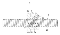
- FIG. 1 shows an external perspective view of the screw device 1 according to the first embodiment of the present invention
- FIG. 2 shows a cross-sectional view taken along the axis of the screw device 1.
- the screw device 1 of the present embodiment includes a screw shaft 2, a nut 3, and a ball 4 as a rolling element interposed between an outer surface groove 2a of the screw shaft 2 and an inner surface groove 3a of the nut 3.
- a spiral outer groove 2a on which the ball 4 rolls is formed on the outer surface of the screw shaft 2.
- the cross-sectional shape of the outer surface groove 2a orthogonal to the longitudinal direction is a Gothic arch shape in which two arcs having a radius slightly larger than the radius of the ball 4 are combined (see FIG. 4B).
- the ball 4 contacts the outer surface groove 2a at two points.
- the screw shaft 2 is fitted into the nut 3.
- a flange 3b is provided at one end of the nut 3 in the axial direction for attachment to a counterpart component.
- the outer surface of the nut 3 is substantially cylindrical except for the flange 3b.
- a flat flattened portion 3c is formed on the outer surface of the nut 3.
- the cross-sectional shape of the inner surface groove 3a orthogonal to the longitudinal direction is a Gothic arch shape in which two arcs having a radius slightly larger than the radius of the ball 4 are combined (see FIG. 4B). The ball 4 contacts the inner surface groove 3a at two points.
- the strain sensor 5 is attached to the flattened portion 3c on the outer surface of the nut 3 by an adhesive means such as an adhesive.
- the strain sensor 5 detects the strain on the outer surface of the nut 3 by utilizing the principle that the resistance value changes when the metal or the semiconductor expands and contracts.
- the strain sensor 5 of this embodiment detects the strain of the outer surface of the nut 3 in at least the circumferential direction (Y direction perpendicular to the axis of the screw shaft 2 in FIG. 1).
- the type of the strain sensor 5 is not particularly limited, and for example, it is created by using a metal strain gauge in which a metal resistor is attached on an insulator, a semiconductor strain gauge in which a semiconductor is attached on an insulator, or semiconductor processing technology. MEMS (Micro Electro Mechanical Systems) strain sensors and the like can be used.
- a spiral passage 8 is formed between the outer surface groove 2a of the screw shaft 2 and the inner surface groove 3a of the nut 3.
- a plurality of balls 4 are arranged in the passage 8.
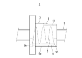
- FIG. 3 shows a side view of the screw device 1.
- the center line of the passage 8 and the center line of the return passage 9 connected to the passage 8 are shown by a chain line.
- the nut 3 is provided with a return passage 9 connected to one end and the other end of the passage 8 so that the balls 4 can circulate.
- the return path 9 is composed of an axial through hole 9a provided in the nut 3 and circulating parts 9b and 9c provided at both ends of the through hole 9a.
- the circulating parts 9b and 9c are mounted in the recesses of the axial end surface of the nut 3.
- the circulation parts 9b, 9c are formed with a direction change path for guiding the ball 4 rolling in the passage 8 to the through hole 9a of the nut 3.
- the return passage 9 may be formed by a return pipe attached to the outer surface of the nut 3.
- a hole 11 is provided between the attachment surface 3e of the nut 3 to which the strain sensor 5 is attached and the inner surface 3d of the nut 3.
- the hole 11 may be provided between the attachment surface 3e of the nut 3 and the inner surface 3d of the nut 3.
- the hole 11 extends in the axial direction. The hole 11 is pierced from the end surface of the nut 3 and passes below the attachment surface 3e.
- the preload system of the screw device 1 of this embodiment is oversize ball preload.
- 4A and 4B are schematic diagrams showing the principle of preloading an oversized ball.
- an oversized ball 4 having a diameter larger than that of the passage 8 between the outer surface groove 2a of the screw shaft 2 and the inner surface groove 3a of the nut 3 is used.
- the ball 4 is compressed between the outer surface groove 2a and the inner surface groove 3a.
- Reference numeral 7 is a contact angle line.
- the pitch P of the outer surface groove 2a of the screw shaft 2 is constant over the entire length of the outer surface groove 2a.
- the pitch P of the inner surface groove 3a of the nut 3 is also constant over the entire length of the inner surface groove 3a.
- FIGS. 5A and 5(b) are schematic views showing the deformation of the nut 3 due to oversize ball preload.
- the solid lines in FIGS. 5A and 5B show the nut 3 before preloading, and the broken lines in FIGS. 5A and 5B show the nut 3 after preloading.
- an oversized ball preload is applied, the nut 3 is deformed so that its outer diameter portion swells. 5A and 5B, the deformation of the nut 3 is exaggerated, but the actual deformation of the nut 3 is slight. This is because in the case of oversize ball preload, the preload applied from the balls 4 to the nut 3 is dispersed over the entire nut 3.
- FIGS. 6A and 6B are schematic diagrams showing the magnitude of strain on the outer surface of the nut 3.
- the magnitude of strain on the outer surface of the nut 3 is indicated by a two-dot chain line.
- FIG. 6( b ) by providing the hole 11 inside the nut 3, the preload F is not transmitted through the hole 11 and the bulge on the outer surface of the nut 3 on the radially outer side of the portion where the hole 11 is provided is prevented. It can be suppressed. Therefore, stress concentration occurs at the boundary between the deformable portion and the hard-to-deform portion of the outer surface of the nut 3, and the amount of strain is increased.
- the strain sensor 5 is arranged in the portion where the strain amount is enlarged, the output of the strain sensor 5 can be increased. For example, the influence of noise can be suppressed, the resolution of the strain sensor 5 can be increased, and the amplifier substrate for the strain sensor 5 can be simplified.
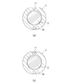
- FIG. 7A shows a sectional view of the nut 3 having one hole 11 formed therein
- FIG. 7B shows a sectional view of the nut 3 having two holes 11 formed therein.
- the nut 3 may be provided with one hole 11 or may be provided with two holes 11 which are parallel to and adjacent to each other.
- the amount of strain increases at the boundary between the deformable portion and the difficult-to-deform portion of the outer surface of the nut 3. By opening the two holes 11, the expanded strain amount can be superimposed.
- FIG. 7( a ) when one hole 11 is formed, it is desirable to arrange the hole 11 at a position 180 degrees apart from the through hole 9 a of the return path 9 in the circumferential direction. Further, as shown in FIG. 7(b), when the two holes 11 are formed, it is desirable to dispose the centers of the two holes 11 at positions 180 degrees apart from the through hole 9a of the return path 9 in the circumferential direction. .. This is because the center of gravity of the nut 3 can be brought closer to the center of the nut 3.
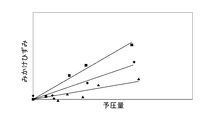
- FIG. 8 is a graph showing the relationship between the preload amount and the apparent strain amount obtained by the experiment.
- the apparent strain amount is a strain amount in the circumferential direction of the outer surface of the nut 3.
- 8 represents a comparative example in which the hole 3 is not provided in the nut 3
- the ⁇ in FIG. 8 represents the present invention example 1 in which one hole 11 is provided in the nut 3, and the solid square in FIG.
- the invention example 2 in which the hole 11 is provided is shown.
- the apparent strain amount in other words, the sensitivity of the strain sensor 5 can be improved about twice as compared with the case where the hole 11 is not provided.
- the apparent strain amount in other words, the sensitivity of the strain sensor 5 can be improved by about 3.5 times as compared with the case where the hole 11 is not provided.
- FIG. 9 is a graph showing changes in the voltage output from the amplifier substrate.
- the horizontal axis represents the usage period of the screw device 1, and the vertical axis represents the voltage output from the amplifier substrate (that is, the preload remaining level). As shown in FIG. 9, it is possible to know the decrease in the preload residual level due to aging.
- IoT may be introduced and the voltage signal output from the amplifier board may be transmitted to the cloud via the Internet line by the transmitter. Then, the failure diagnosis system on the cloud may diagnose the failure of the screw device 1 by performing deep learning on the voltage signal output from the amplifier board using artificial intelligence.
- the configuration of the screw device of this embodiment has been described above.
- the screw device 1 of the present embodiment has the following effects.
- the hole 11 is provided between the attachment surface 3e of the nut 3 to which the strain sensor 5 is attached and/or the vicinity thereof and the inner surface 3d of the nut 3, a preload is applied to the outer surface of the nut 3 at the portion where the hole 11 is provided. It becomes difficult to communicate. Since stress concentration occurs at the boundary between the deformable portion and the hard-to-deform portion of the outer surface of the nut 3, the amount of strain is increased, so that the strain sensor 5 can easily detect the preload.
- the sensitivity of the strain sensor 5 can be improved, for example, about twice as compared with the case where the hole 11 is not provided.
- the sensitivity of the strain sensor 5 can be improved by, for example, about 3.5 times as compared with the case where the holes 11 are not provided.
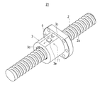
- FIG. 10 shows an external perspective view of the screw device 21 according to the second embodiment of the present invention
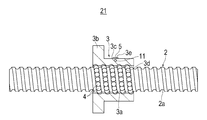
- FIG. 11 shows a cross-sectional view of the screw device 21 taken along the axis.
- the screw device 21 of the second embodiment also includes the screw shaft 2, the nut 3, and the balls 4 as rolling elements interposed between the outer surface groove 2 a of the screw shaft 2 and the inner surface groove 3 a of the nut 3.
- the screw device 1 of the first embodiment is an oversized ball preload screw device 1
- the screw device 21 of the second embodiment is an offset preload screw device 21. That is, as shown in FIGS. 12A and 12B, a part 3a1 of the inner surface groove 3a of the nut 3 is offset in the axial direction of the nut 3 with respect to another part 3a2 of the inner surface groove 3a of the nut 3. There is.
- the circulation circuit in which a part 3a1 of the inner surface groove 3a is used and the circulation circuit in which another part 3a2 of the inner surface groove 3a is used are different from each other.
- the lead of the part 3a1 of the inner surface groove 3a is L
- the lead of the other part 3a2 of the inner surface groove 3a is L
- the lead of the offset portion 18 between the part 3a1 and the other part 3a2 is L+ ⁇ . Is. It should be noted that offset preload may be applied in the one inner groove 3a, or offset preload may be applied between the two inner grooves 3a.
- the cross-sectional shape of the outer surface groove 2a of the screw shaft 2 is a circular arc shape having a single arc having a radius slightly larger than the radius of the ball 4.
- the ball 4 contacts the outer surface groove 2a at one point.
- the cross-sectional shape of the inner surface groove 3 a of the nut 3 is a circular arc shape having a single arc having a radius slightly larger than the radius of the ball 4.
- the ball 4 contacts the inner surface groove 3a at one point.
- Reference numeral 7 is a contact angle line.
- the strain sensor 5 is attached to the flattened portion 3c on the outer surface of the nut 3 by an adhesive means such as an adhesive.
- a hole 11 is provided between the attachment surface 3e of the nut 3 to which the strain sensor 5 is attached and the inner surface 3d of the nut 3.
- the hole 11 may be provided between the attachment surface 3e of the nut 3 and the inner surface 3d of the nut 3.
- the hole 11 extends in a direction perpendicular to the axial direction. Two adjacent parallel holes 11 may be provided.
- the hole 11 is opened from the side surface of the nut 3 and passes below the attachment surface 3e.
- the hole 11 is provided between the attachment surface 3e of the nut 3 to which the strain sensor 5 is attached and/or the vicinity thereof and the inner surface 3d of the nut 3, the hole 11 is formed.
- the preload is less likely to be transmitted to the outer surface of the nut 3 at the provided portion. Since stress concentration occurs at the boundary between the deformable portion and the hard-to-deform portion of the outer surface of the nut 3, the amount of strain is increased, so that the strain sensor 5 can easily detect the preload.
- the preload can be detected easily by detecting the amount of axial strain on the outer surface of the nut 3. This is because the offset preload causes the nut 3 to deform so as to extend in the axial direction (X direction in FIG. 10).
- rollers may be used instead of balls for the rolling elements.
- the cross-sectional shape of the hole orthogonal to the extending direction of the hole is circular, but the shape is not limited to circular and may be square or the like. Further, the hole may be a linear or arc-shaped long hole, and/or a slit shape.
- the inside of the hole is a space, but the inside of the hole can be filled with a filling material.
Landscapes
- Engineering & Computer Science (AREA)
- General Engineering & Computer Science (AREA)
- Mechanical Engineering (AREA)
- Transmission Devices (AREA)
- Support Of The Bearing (AREA)
- Moving Of Heads (AREA)
Abstract
シングルナットで予圧を与えるねじ装置において、予圧を容易に検知できるねじ装置を提供する。 本発明のねじ装置(1)は、螺旋状の外面溝(2a)を有するねじ軸(2)と、ねじ軸(2)が嵌められ、螺旋状の内面溝(3a)及び戻し路(9)を有し、外面溝(2a)と内面溝(3a)との間に形成される通路(8)が戻し路(9)に繋がるナット(3)と、通路(8)と戻し路(9)に配置される複数の転動体(4)と、ナット(3)の外面に貼り付けられるひずみセンサ(5)と、を備える。ひずみセンサ(5)が貼り付けられるナット(3)の貼付け面(3e)及び/又はその近傍とナット(3)の内面(3d)との間に少なくとも1つの穴(11)を設ける。
Description
本発明は、予圧検知可能なねじ装置に関する。
ねじ装置は、ねじ軸と、ナットと、ねじ軸とナットとの間に介在する複数の転動体と、を備える。モータ等によってねじ軸を回転させると、ナットが直線運動する。ねじ装置は、回転運動と直線運動との間で運動を変換する機械要素として使用される。ねじ軸が回転する間、転動体が転がり運動するので、摩擦抵抗を減らすことができるという特徴がある。
ねじ装置の剛性を向上させ、位置決め精度を向上させるために、ねじ装置には予圧が与えられる。ねじ装置の予圧方式として、ダブルナット予圧、オフセット予圧、オーバーサイズボール予圧が知られている。ダブルナット予圧においては、ナットを2つ使用し、2つのナットの間にスペーサを入れて、各ナットのねじ軸、ナット及びボール間に生ずる軸方向隙間をゼロにする。オフセット予圧は、シングルナットで予圧を与える方式であり、ナットの螺旋状の内面溝の一部を内面溝の他の一部に対してナットの軸方向にオフセットさせることで、軸方向隙間をゼロにする。オーバーサイズボール予圧は、シングルナットで予圧を与える方式であり、ナットの螺旋状の内面溝とねじ軸の螺旋状の外面溝との間の通路よりも大きい転動体を挿入することで、軸方向隙間をゼロにする。
ねじ装置を長期間使用すると、転動体、ねじ軸、ナットが摩耗する。これらが摩耗すると、ねじ装置の予圧が低下し、ねじ装置の剛性、位置決め精度が低下する。予圧を検知するために、特許文献1には、ダブルナット予圧方式のボールねじにおいて、2つのナットの間にスペーサとしてひずみセンサを介在させるものが開示されている。ひずみセンサによって2つのナットの対向面に働く軸方向力を検出することによって、経年変化に起因する予圧の低下を監視することができる。
シングルナットで予圧を与えるねじ装置には、ダブルナットで予圧を与えるねじ装置よりも予圧を検知しにくいという課題がある。なぜならば、たとえナットの外面にひずみセンサを貼り付けても、予圧荷重に起因するナットの外面のひずみ量が小さいからである。
そこで本発明は、シングルナットで予圧を与えるねじ装置において、予圧を容易に検知できるねじ装置を提供することを目的とする。
上記課題を解決するために、本発明の一態様は、螺旋状の外面溝を有するねじ軸と、前記ねじ軸が嵌められ、螺旋状の内面溝及び戻し路を有し、前記外面溝と前記内面溝との間に形成される通路が前記戻し路に繋がるナットと、前記通路と前記戻し路に配置される複数の転動体と、前記ナットの外面に貼り付けられるひずみセンサと、を備え、前記ひずみセンサが貼り付けられる前記ナットの貼付け面及び/又はその近傍と前記ナットの内面との間に少なくとも1つの穴を設ける予圧検知可能なねじ装置である。
本発明の一態様によれば、ひずみセンサが貼り付けられるナットの貼付け面及び/又はその近傍とナットの内面との間に少なくとも1つの穴を設けるので、少なくとも1つの穴を設けた部分において、ナットの外面に予圧荷重が伝わりにくくなる。ナットの外面の変形する部分と変形しにくい部分との境目に応力集中が発生し、ひずみ量が拡大されるので、ひずみセンサによる予圧の検知が容易になる。
以下、添付図面を参照して、本発明の実施形態の予圧検知可能なねじ装置(以下、単にねじ装置という)を詳細に説明する。ただし、本発明のねじ装置は、種々の形態で具体化することができ、本明細書に記載される実施形態に限定されるものではない。本実施形態は、明細書の開示を十分にすることによって、当業者が発明の範囲を十分に理解できるようにする意図をもって提供されるものである。
(第1の実施形態)
(第1の実施形態)
図1は、本発明の第1の実施形態のねじ装置1の外観斜視図を示し、図2は、ねじ装置1の軸線に沿った断面図を示す。本実施形態のねじ装置1は、ねじ軸2と、ナット3と、ねじ軸2の外面溝2aとナット3の内面溝3aとの間に介在する転動体としてのボール4と、を備える。
ねじ軸2の外面には、ボール4が転がる螺旋状の外面溝2aが形成される。外面溝2aの長さ方向に直交する断面形状は、ボール4の半径よりも僅かに大きな半径を持つ2つの円弧を組み合わせたゴシックアーチ状である(図4(b)参照)。ボール4は、外面溝2aに2点で接触する。
ナット3には、ねじ軸2が嵌められる。ナット3の軸方向の一端部には、相手部品に取りつけるためのフランジ3bが設けられる。ナット3の外面は、フランジ3bを除いて略円筒状である。ナット3の外面には、平坦な平取り部3cが形成される。ナット3の内面には、ねじ軸2の外面溝2aに対向する螺旋状の内面溝3aが形成される。内面溝3aの長さ方向に直交する断面形状は、ボール4の半径よりも僅かに大きな半径を持つ2つの円弧を組み合わせたゴシックアーチ状である(図4(b)参照)。ボール4は、内面溝3aに2点で接触する。
図1及び図2に示すように、ナット3の外面の平取り部3cには、接着剤等の接着手段によってひずみセンサ5が貼り付けられる。ひずみセンサ5は、金属又は半導体が伸び縮みすると、抵抗値が変化するという原理を利用して、ナット3の外面のひずみを検出する。この実施形態のひずみセンサ5は、ナット3の外面の少なくとも円周方向(図1のねじ軸2の軸線と直角なY方向)のひずみを検出する。
ひずみセンサ5の種類は、特に限定されるものではなく、例えば絶縁体上に金属の抵抗体を取り付けた金属ひずみゲージ、絶縁体上に半導体を取り付けた半導体ひずみゲージ、半導体加工技術を使って作成されたMEMS(Micro Electro Mechanical Systems)ひずみセンサ等を使用することができる。
図2に示すように、ねじ軸2の外面溝2aとナット3の内面溝3aとの間に螺旋状の通路8が形成される。この通路8には、複数のボール4が配置される。
図3は、ねじ装置1の側面図を示す。図3には、通路8の中心線と通路8に繋がる戻し路9の中心線を一点鎖線で示す。図3に示すように、ナット3には、ボール4が循環できるように、この通路8の一端と他端に繋がる戻し路9が設けられる。戻し路9は、ナット3に設けた軸方向の貫通穴9aと、貫通穴9aの両端部に設けられる循環部品9b,9cによって構成される。循環部品9b、9cは、ナット3の軸方向の端面の凹部に装着される。循環部品9b,9cには、通路8を転がるボール4をナット3の貫通穴9aに導く方向転換路が形成される。なお、戻し路9をナット3の外面に取り付けられるリターンパイプによって構成してもよい。
図1及び図2に示すように、ひずみセンサ5が貼り付けられるナット3の貼付け面3eとナット3の内面3dとの間には、穴11が設けられる。穴11をナット3の貼付け面3eの近傍とナット3の内面3dとの間に設けることもできる。穴11は、軸方向に延びる。穴11は、ナット3の端面から空けられ、貼付け面3eの下方を通過する。
本実施形態のねじ装置1の予圧方式は、オーバーサイズボール予圧である。図4(a)(b)は、オーバーサイズボール予圧の原理を示す模式図である。ボール4には、ねじ軸2の外面溝2aとナット3の内面溝3aとの間の通路8よりも直径が大きいオーバーサイズのボール4が使用される。ボール4は、外面溝2aと内面溝3aとの間で圧縮される。符号7は、接触角線である。ねじ軸2の外面溝2aのピッチPは、外面溝2aの全長にわたって一定である。ナット3の内面溝3aのピッチPも、内面溝3aの全長にわたって一定である。
図5(a)(b)は、オーバーサイズボール予圧によるナット3の変形を示す模式図である。図5(a)(b)の実線が予圧をかける前のナット3を示し、図5(a)(b)の破線が予圧をかけた後のナット3を示す。オーバーサイズボール予圧をかけた場合、ナット3は、その外径部が膨らむように変形する。図5(a)(b)には、ナット3の変形を誇大に示すが、ナット3の実際の変形は僅かである。オーバーサイズボール予圧の場合、ボール4からナット3に働く予圧荷重がナット3の全体に分散するからである。
図6(a)(b)は、ナット3の外面のひずみ量の大きさを示す模式図である。図6(a)(b)において、ナット3の外面のひずみ量の大きさを2点鎖線で示す。図6(b)に示すように、ナット3の内部に穴11を設けることで、予圧荷重Fが穴11を伝わらず、穴11を設けた部分の半径方向外側のナット3の外面の膨らみが抑えられる。このため、ナット3の外面の変形する部分と変形しにくい部分との境目に応力集中が発生し、ひずみ量が拡大される。ひずみ量が拡大された部分にひずみセンサ5を配置すれば、ひずみセンサ5の出力を大きくすることができる。例えば、ノイズの影響を抑えたり、ひずみセンサ5の分解能を上げたり、ひずみセンサ5用のアンプ基板を簡素化できたりする。
図7(a)は、1つの穴11を空けたナット3の断面図を示し、図7(b)は2つの穴11を空けたナット3の断面図を示す。ナット3には、1つの穴11を空けてもよいし、互いに平行で隣接する2つの穴11を空けてもよい。上記のように、ひずみ量は、ナット3の外面の変形する部分と変形しにくい部分との境目において拡大する。2つの穴11を空けることで、拡大させたひずみ量を重畳させることができる。
図7(a)に示すように、1つの穴11を空ける場合、穴11を戻し路9の貫通穴9aと円周方向に180度離れた位置に配置するのが望ましい。また、図7(b)に示すように、2つの穴11を空ける場合、2つの穴11の中心を 戻し路9の貫通穴9aと円周方向に180度離れた位置に配置するのが望ましい。ナット3の重心をナット3の中心に近づけられるからである。
図8は、実験により求めた予圧量とみかけひずみ量との関係を示すグラフである。みかけひずみ量は、ナット3の外面の円周方向のひずみ量である。図8の▲がナット3に穴11を設けない比較例を表し、図8の◆がナット3に1つの穴11を設けた本発明例1を表し、図8の■がナット3に2つの穴11を設けた本発明例2を表す。ナット3に1つの穴11を設けることで、穴11を設けない場合に比べて、みかけひずみ量、言い換えればひずみセンサ5の感度を約2倍に向上させることができる。また、ナット3に2つの穴11を設けることで、穴11を設けない場合に比べて、みかけひずみ量、言い換えればひずみセンサ5の感度を約3.5倍に向上させることができる。
ねじ装置1を長期間使用すると、ボール4、ねじ軸2、ナット3が摩耗し、ねじ装置1の予圧が低下する。予圧が低下すると、ナット3の外面のひずみが小さくなり、ひずみセンサ5の抵抗値が低下する。ひずみセンサ5は、図示しないアンプ基板に接続される。アンプ基板は、ひずみセンサ5の抵抗値に基づいた電圧信号を出力する。アンプ基板の電圧信号によって、予圧の低下を監視することができる。図9は、アンプ基板が出力する電圧の推移を示すグラフである。横軸はねじ装置1の使用期間であり、縦軸はアンプ基板が出力する電圧(すなわち予圧残存レベル)である。図9に示すように、経年変化に伴う予圧残存レベルの低下を知ることができる。
なお、IoTを導入し、アンプ基板が出力する電圧信号を送信機によってインターネット回線を通じてクラウドに送信してもよい。そして、クラウド上の故障診断システムが、アンプ基板が出力する電圧信号を人口知能を用いた深層学習(ディープラーニング)し、ねじ装置1の故障を診断してもよい。
以上に本実施形態のねじ装置の構成を説明した。本実施形態のねじ装置1によれば、以下の効果を奏する。
ひずみセンサ5が貼り付けられるナット3の貼付け面3e及び/又はその近傍とナット3の内面3dとの間に穴11を設けるので、穴11を設けた部分において、ナット3の外面に予圧荷重が伝わりにくくなる。ナット3の外面の変形する部分と変形しにくい部分との境目に応力集中が発生し、ひずみ量が拡大されるので、ひずみセンサ5による予圧の検知が容易になる。
オーバーサイズボール予圧の場合、ナット3の円周方向のひずみを検出することにより、ひずみセンサ5による予圧の検知が容易になる。
1つの穴11を設けることで、穴11を設けない場合に比べて、ひずみセンサ5の感度を例えば約2倍に向上させることができる。
平行な2つの穴11を設けることで、穴11を設けない場合に比べて、ひずみセンサ5の感度を例えば約3.5倍に向上させることができる。
ひずみセンサ5をナット3の平取り部3cに取り付けることで、ナット3にひずみセンサ5を取り付けるのが容易である。
(第2の実施形態)
(第2の実施形態)
図10は、本発明の第2の実施形態のねじ装置21の外観斜視図を示し、図11は、ねじ装置21の軸線に沿った断面図を示す。第2の実施形態のねじ装置21も、ねじ軸2、ナット3、ねじ軸2の外面溝2aとナット3の内面溝3aとの間に介在する転動体としてのボール4を備える。
第1の実施形態のねじ装置1は、オーバーサイズボール予圧のねじ装置1であるのに対し、第2の実施形態のねじ装置21は、オフセット予圧のねじ装置21である。すなわち、図12(a)(b)に示すように、ナット3の内面溝3aの一部3a1をナット3の内面溝3aの他の一部3a2に対してナット3の軸方向にオフセットさせている。内面溝3aの一部3a1が使用される循環回路と、内面溝3aの他の一部3a2が使用される循環回路とは、互いに異なる。内面溝3aの一部3a1のリードはLであり、内面溝3aの他の一部3a2のリードはLであり、一部3a1と他の一部3a2との間のオフセット部18のリードはL+αである。なお、1条の内面溝3a内でオフセット予圧をかけてもよいし、2条の内面溝3aの条間でオフセット予圧をかけてもよい。
図12(b)に示すように、ねじ軸2の外面溝2aの断面形状は、ボール4の半径よりも僅かに大きな半径を持つ単一の円弧からなるサーキュラーアーク状である。ボール4は、外面溝2aに1点で接触する。ナット3の内面溝3aの断面形状は、ボール4の半径よりも僅かに大きな半径を持つ単一の円弧からなるサーキュラーアーク状である。ボール4は、内面溝3aに1点で接触する。符号7は、接触角線である。
図10及び図11に示すように、ナット3の外面の平取り部3cには、接着剤等の接着手段によってひずみセンサ5が貼り付けられる。ひずみセンサ5が取り付けられるナット3の貼付け面3eとナット3の内面3dとの間には、穴11が設けられる。穴11をナット3の貼付け面3eの近傍とナット3の内面3dとの間に設けてもよい。穴11は、軸方向に直角な方向に延びる。隣接する平行な2つの穴11を設けてもよい。穴11はナット3の側面から空けられ、貼付け面3eの下方を通過する。
第2の実施形態のねじ装置21によれば、ひずみセンサ5が貼り付けられるナット3の貼付け面3e及び/又はその近傍とナット3の内面3dとの間に穴11を設けるので、穴11を設けた部分において、ナット3の外面に予圧荷重が伝わりにくくなる。ナット3の外面の変形する部分と変形しにくい部分との境目に応力集中が発生し、ひずみ量が拡大されるので、ひずみセンサ5による予圧の検知が容易になる。
オフセット予圧の場合、ナット3の外面の軸方向のひずみ量を検知することにより、予圧の検知が容易になる。オフセット予圧によってナット3は軸方向(図10のX方向)に延びるように変形するからである。
なお、本発明は上記実施形態に限られることはなく、本発明の要旨を変更しない範囲で他の実施形態に具現化可能である。例えば、転動体にはボールの替わりにローラを使用してもよい。
上記実施形態では、穴の延びる方向と直交する穴の断面形状が円形であるが、円形に限られることはなく、四角形等であってもよい。また、穴は、直線状もしくは円弧状の長穴、及び/又はスリット状であってもよい。
上記実施形態では、穴の内部が空間になっているが、穴の内部を充填材によって充填することもできる。
本明細書は、2019年2月6日出願の特願2019-019349に基づく。この内容はすべてここに含めておく。
1,21…ねじ装置、2…ねじ軸、2a…外面溝、3…ナット、3a…内面溝、3a1…ナットの内面溝の一部、3a2…ナットの内面溝の他の一部、3c…平取り部、3d…ナットの内面、3e…貼付け面、4…ボール(転動体)、5…ひずみセンサ、8…通路、9…戻し路、11…穴
Claims (5)
- 螺旋状の外面溝を有するねじ軸と、
前記ねじ軸が嵌められ、螺旋状の内面溝及び戻し路を有し、前記外面溝と前記内面溝との間に形成される通路が前記戻し路に繋がるナットと、
前記通路と前記戻し路に配置される複数の転動体と、
前記ナットの外面に貼り付けられるひずみセンサと、を備え、
前記ひずみセンサが貼り付けられる前記ナットの貼付け面及び/又はその近傍と前記ナットの内面との間に少なくとも1つの穴を設ける予圧検知可能なねじ装置。 - 前記ねじ装置の予圧が、前記通路よりも大きい前記転動体を使用するオーバーサイズボール予圧であり、
前記ひずみセンサが前記ナットの少なくとも円周方向のひずみを検出することを特徴とする請求項1に記載の予圧検知可能なねじ装置。 - 前記ねじ装置の予圧が、前記ナットの前記内面溝の一部を前記ナットの前記内面溝の他の一部に対して前記ナットの軸方向にオフセットさせるオフセット予圧であり、
前記ひずみセンサが前記ナットの軸方向のひずみを検出することを特徴とする請求項1に記載の予圧検知可能なねじ装置。 - 前記少なくとも1つの穴が互いに平行で隣接する少なくとも2つの穴であることを特徴とする請求項1ないし3のいずれか一項に記載の予圧検知可能なねじ装置。
- 前記ひずみセンサが前記ナットの前記外面の平取り部に貼り付けられることを特徴とする請求項1ないし4のいずれか一項に記載の予圧検知可能なねじ装置。
Priority Applications (4)
| Application Number | Priority Date | Filing Date | Title |
|---|---|---|---|
| US17/428,731 US11892062B2 (en) | 2019-02-06 | 2020-01-20 | Preload detectable screw device |
| CN202080013077.6A CN113423972B (zh) | 2019-02-06 | 2020-01-20 | 能够检测预压的丝杠装置 |
| DE112020000713.8T DE112020000713T5 (de) | 2019-02-06 | 2020-01-20 | Vorspannungsdetektierbare Spindelvorrichtung |
| KR1020217027646A KR102670872B1 (ko) | 2019-02-06 | 2020-01-20 | 예압 검지 가능한 나사 장치 |
Applications Claiming Priority (2)
| Application Number | Priority Date | Filing Date | Title |
|---|---|---|---|
| JP2019-019349 | 2019-02-06 | ||
| JP2019019349A JP7166185B2 (ja) | 2019-02-06 | 2019-02-06 | 予圧検知可能なねじ装置 |
Publications (1)
| Publication Number | Publication Date |
|---|---|
| WO2020162145A1 true WO2020162145A1 (ja) | 2020-08-13 |
Family
ID=71947231
Family Applications (1)
| Application Number | Title | Priority Date | Filing Date |
|---|---|---|---|
| PCT/JP2020/001652 Ceased WO2020162145A1 (ja) | 2019-02-06 | 2020-01-20 | 予圧検知可能なねじ装置 |
Country Status (7)
| Country | Link |
|---|---|
| US (1) | US11892062B2 (ja) |
| JP (1) | JP7166185B2 (ja) |
| KR (1) | KR102670872B1 (ja) |
| CN (1) | CN113423972B (ja) |
| DE (1) | DE112020000713T5 (ja) |
| TW (1) | TWI821517B (ja) |
| WO (1) | WO2020162145A1 (ja) |
Families Citing this family (2)
| Publication number | Priority date | Publication date | Assignee | Title |
|---|---|---|---|---|
| US12326176B2 (en) | 2021-05-14 | 2025-06-10 | Jtekt Bearings North America Llc | Ball screw assembly with integral force measurement |
| US20240392863A1 (en) | 2023-05-24 | 2024-11-28 | Jtekt Bearings North America Llc | Actuator having wiring pathway arrangement |
Citations (3)
| Publication number | Priority date | Publication date | Assignee | Title |
|---|---|---|---|---|
| JPH05141498A (ja) * | 1991-11-20 | 1993-06-08 | Yotaro Hatamura | 送りねじ装置 |
| JP2007333195A (ja) * | 2006-06-19 | 2007-12-27 | Nsk Ltd | ボールねじ装置およびそのモニタ装置 |
| JP2017150502A (ja) * | 2016-02-22 | 2017-08-31 | 日本精工株式会社 | ボールねじ、ボールねじのサーキット外ボール検出方法 |
Family Cites Families (23)
| Publication number | Priority date | Publication date | Assignee | Title |
|---|---|---|---|---|
| WO1993009911A1 (fr) | 1991-11-15 | 1993-05-27 | Yotaro Hatamura | Dispositif a vis de commande et systeme de commande de micro-mouvement a positionnement de precision |
| JP3365651B2 (ja) * | 1993-05-25 | 2003-01-14 | Thk株式会社 | 直線案内用のレール等の異形引抜き材を製造するための引抜き加工方法 |
| JP5031957B2 (ja) * | 2001-08-30 | 2012-09-26 | Thk株式会社 | リニアアクチュエータ |
| JP2004257466A (ja) | 2003-02-26 | 2004-09-16 | Nsk Ltd | ボールねじ |
| EP1515066B1 (en) * | 2003-09-10 | 2014-01-08 | Nsk Ltd | Ball screw apparatus |
| EP1775063B1 (en) * | 2005-10-12 | 2018-07-11 | NSK Ltd. | Assembly apparatus for ball screw device |
| JP2007225024A (ja) | 2006-02-23 | 2007-09-06 | Nsk Ltd | ボールねじ装置 |
| DE102007049832A1 (de) * | 2007-10-18 | 2009-04-23 | Volkswagen Ag | Elektromechanische Lenkung mit einem Kugelgewindetrieb |
| JP2009257806A (ja) * | 2008-04-14 | 2009-11-05 | Nsk Ltd | 転がり直動装置の異常判定方法および異常判定装置 |
| US9279487B1 (en) * | 2009-09-30 | 2016-03-08 | David B. Guglietti | Ball screw and parts |
| DE102010036096B4 (de) * | 2010-09-01 | 2016-07-28 | Gottfried Wilhelm Leibniz Universität Hannover | Kugelgewindetrieb |
| US8966996B2 (en) * | 2011-07-27 | 2015-03-03 | Tri-Force Management Corporation | Force sensor |
| JP2013200032A (ja) * | 2011-11-18 | 2013-10-03 | Nsk Ltd | ボールねじ装置 |
| DE102012007329B4 (de) * | 2012-04-12 | 2014-02-27 | Volkswagen Aktiengesellschaft | Welle-Nabe-Verbindung |
| US9464703B2 (en) * | 2013-07-17 | 2016-10-11 | National Chung Cheng University | Ball screw capable of sensing preload |
| TW201600222A (zh) * | 2014-06-25 | 2016-01-01 | Hiwin Tech Corp | 預壓力殘存率之偵測方法 |
| US10436300B2 (en) * | 2014-08-26 | 2019-10-08 | Hiwin Technologies Corp. | Offset preload ball screw with expandable loading area |
| JP6561586B2 (ja) | 2015-05-28 | 2019-08-21 | 日本精工株式会社 | ボールねじ |
| JP6519328B2 (ja) * | 2015-06-09 | 2019-05-29 | 日本精工株式会社 | 電動パワーステアリング装置 |
| EP3282146B1 (en) * | 2016-08-12 | 2021-06-30 | Ratier-Figeac SAS | Secondary load path dectection |
| JP6669275B2 (ja) * | 2016-11-11 | 2020-03-18 | 日本精工株式会社 | ボールねじ装置 |
| JP2019019349A (ja) | 2017-07-12 | 2019-02-07 | 住友電気工業株式会社 | 磁性粉末の製造方法、及び磁性粉末 |
| TWI664365B (zh) * | 2017-12-29 | 2019-07-01 | 財團法人工業技術研究院 | 一種具傾斜偵測器的滾珠螺桿 |
-
2019
- 2019-02-06 JP JP2019019349A patent/JP7166185B2/ja active Active
-
2020
- 2020-01-20 CN CN202080013077.6A patent/CN113423972B/zh active Active
- 2020-01-20 DE DE112020000713.8T patent/DE112020000713T5/de active Pending
- 2020-01-20 US US17/428,731 patent/US11892062B2/en active Active
- 2020-01-20 WO PCT/JP2020/001652 patent/WO2020162145A1/ja not_active Ceased
- 2020-01-20 KR KR1020217027646A patent/KR102670872B1/ko active Active
- 2020-02-03 TW TW109103126A patent/TWI821517B/zh active
Patent Citations (3)
| Publication number | Priority date | Publication date | Assignee | Title |
|---|---|---|---|---|
| JPH05141498A (ja) * | 1991-11-20 | 1993-06-08 | Yotaro Hatamura | 送りねじ装置 |
| JP2007333195A (ja) * | 2006-06-19 | 2007-12-27 | Nsk Ltd | ボールねじ装置およびそのモニタ装置 |
| JP2017150502A (ja) * | 2016-02-22 | 2017-08-31 | 日本精工株式会社 | ボールねじ、ボールねじのサーキット外ボール検出方法 |
Also Published As
| Publication number | Publication date |
|---|---|
| DE112020000713T5 (de) | 2021-11-11 |
| CN113423972A (zh) | 2021-09-21 |
| KR20210119513A (ko) | 2021-10-05 |
| JP7166185B2 (ja) | 2022-11-07 |
| US20220128136A1 (en) | 2022-04-28 |
| CN113423972B (zh) | 2023-06-06 |
| JP2020125829A (ja) | 2020-08-20 |
| KR102670872B1 (ko) | 2024-05-31 |
| US11892062B2 (en) | 2024-02-06 |
| TW202043649A (zh) | 2020-12-01 |
| TWI821517B (zh) | 2023-11-11 |
Similar Documents
| Publication | Publication Date | Title |
|---|---|---|
| WO2007006262A1 (de) | Lageranordnung zur lagerung wenigstens eines maschinenelements an einer stütze | |
| US11320028B2 (en) | Preload detectable screw device | |
| US10989614B2 (en) | Torque sensor and robot | |
| JP7166185B2 (ja) | 予圧検知可能なねじ装置 | |
| JP6549812B2 (ja) | トルクセンサおよびロボット | |
| IT201800004657A1 (it) | Gruppo mozzo ruota provvisto di un innovativo supporto porta sensore | |
| JP6952569B2 (ja) | 予圧検知可能なねじ装置 | |
| JP7166216B2 (ja) | 予圧検知可能なねじ装置 | |
| JP5063270B2 (ja) | センサ付車輪用軸受 | |
| JP2019074193A (ja) | 予圧検知可能なねじ装置 | |
| JP4650510B2 (ja) | フレッチングによる異音発生予測方法 | |
| EP2944548A1 (en) | Ball joint and steering device including the same | |
| JP5202348B2 (ja) | センサ付車輪用軸受装置 | |
| JP7275989B2 (ja) | 負荷荷重検出ユニット | |
| CN112901652A (zh) | 具有距离传感器和锥形槽的轴承 | |
| JP2010090982A (ja) | センサ付車輪用軸受 | |
| JP4259346B2 (ja) | 鉄道車両用センサ付軸受装置 | |
| JP2006226477A (ja) | センサ付き転がり軸受装置 | |
| JP2006144908A (ja) | 回転センサ付軸受および回転物への組み込み方法 | |
| JP4127163B2 (ja) | フレッチング発生予測方法 | |
| CN204572974U (zh) | 滚珠丝杠装置 | |
| JP2008286220A (ja) | センサ付車輪用軸受 |
Legal Events
| Date | Code | Title | Description |
|---|---|---|---|
| 121 | Ep: the epo has been informed by wipo that ep was designated in this application |
Ref document number: 20752594 Country of ref document: EP Kind code of ref document: A1 |
|
| ENP | Entry into the national phase |
Ref document number: 20217027646 Country of ref document: KR Kind code of ref document: A |
|
| 122 | Ep: pct application non-entry in european phase |
Ref document number: 20752594 Country of ref document: EP Kind code of ref document: A1 |