WO2020162088A1 - 固定子の製造方法及び固定子コア - Google Patents
固定子の製造方法及び固定子コア Download PDFInfo
- Publication number
- WO2020162088A1 WO2020162088A1 PCT/JP2020/000230 JP2020000230W WO2020162088A1 WO 2020162088 A1 WO2020162088 A1 WO 2020162088A1 JP 2020000230 W JP2020000230 W JP 2020000230W WO 2020162088 A1 WO2020162088 A1 WO 2020162088A1
- Authority
- WO
- WIPO (PCT)
- Prior art keywords
- stator core
- varnish
- temperature
- coil
- stator
- Prior art date
- Legal status (The legal status is an assumption and is not a legal conclusion. Google has not performed a legal analysis and makes no representation as to the accuracy of the status listed.)
- Ceased
Links
Images
Classifications
-
- H—ELECTRICITY
- H02—GENERATION; CONVERSION OR DISTRIBUTION OF ELECTRIC POWER
- H02K—DYNAMO-ELECTRIC MACHINES
- H02K15/00—Processes or apparatus specially adapted for manufacturing, assembling, maintaining or repairing of dynamo-electric machines
- H02K15/12—Impregnating, moulding insulation, heating or drying of windings, stators, rotors or machines
-
- B—PERFORMING OPERATIONS; TRANSPORTING
- B29—WORKING OF PLASTICS; WORKING OF SUBSTANCES IN A PLASTIC STATE IN GENERAL
- B29C—SHAPING OR JOINING OF PLASTICS; SHAPING OF MATERIAL IN A PLASTIC STATE, NOT OTHERWISE PROVIDED FOR; AFTER-TREATMENT OF THE SHAPED PRODUCTS, e.g. REPAIRING
- B29C45/00—Injection moulding, i.e. forcing the required volume of moulding material through a nozzle into a closed mould; Apparatus therefor
- B29C45/14—Injection moulding, i.e. forcing the required volume of moulding material through a nozzle into a closed mould; Apparatus therefor incorporating preformed parts or layers, e.g. injection moulding around inserts or for coating articles
- B29C45/14467—Joining articles or parts of a single article
-
- B—PERFORMING OPERATIONS; TRANSPORTING
- B29—WORKING OF PLASTICS; WORKING OF SUBSTANCES IN A PLASTIC STATE IN GENERAL
- B29C—SHAPING OR JOINING OF PLASTICS; SHAPING OF MATERIAL IN A PLASTIC STATE, NOT OTHERWISE PROVIDED FOR; AFTER-TREATMENT OF THE SHAPED PRODUCTS, e.g. REPAIRING
- B29C45/00—Injection moulding, i.e. forcing the required volume of moulding material through a nozzle into a closed mould; Apparatus therefor
- B29C45/17—Component parts, details or accessories; Auxiliary operations
- B29C45/72—Heating or cooling
- B29C45/73—Heating or cooling of the mould
-
- B—PERFORMING OPERATIONS; TRANSPORTING
- B29—WORKING OF PLASTICS; WORKING OF SUBSTANCES IN A PLASTIC STATE IN GENERAL
- B29C—SHAPING OR JOINING OF PLASTICS; SHAPING OF MATERIAL IN A PLASTIC STATE, NOT OTHERWISE PROVIDED FOR; AFTER-TREATMENT OF THE SHAPED PRODUCTS, e.g. REPAIRING
- B29C45/00—Injection moulding, i.e. forcing the required volume of moulding material through a nozzle into a closed mould; Apparatus therefor
- B29C45/14—Injection moulding, i.e. forcing the required volume of moulding material through a nozzle into a closed mould; Apparatus therefor incorporating preformed parts or layers, e.g. injection moulding around inserts or for coating articles
- B29C2045/1486—Details, accessories and auxiliary operations
-
- B—PERFORMING OPERATIONS; TRANSPORTING
- B29—WORKING OF PLASTICS; WORKING OF SUBSTANCES IN A PLASTIC STATE IN GENERAL
- B29C—SHAPING OR JOINING OF PLASTICS; SHAPING OF MATERIAL IN A PLASTIC STATE, NOT OTHERWISE PROVIDED FOR; AFTER-TREATMENT OF THE SHAPED PRODUCTS, e.g. REPAIRING
- B29C45/00—Injection moulding, i.e. forcing the required volume of moulding material through a nozzle into a closed mould; Apparatus therefor
- B29C45/17—Component parts, details or accessories; Auxiliary operations
- B29C45/72—Heating or cooling
- B29C45/73—Heating or cooling of the mould
- B29C2045/7343—Heating or cooling of the mould heating or cooling different mould parts at different temperatures
-
- B—PERFORMING OPERATIONS; TRANSPORTING
- B29—WORKING OF PLASTICS; WORKING OF SUBSTANCES IN A PLASTIC STATE IN GENERAL
- B29L—INDEXING SCHEME ASSOCIATED WITH SUBCLASS B29C, RELATING TO PARTICULAR ARTICLES
- B29L2031/00—Other particular articles
- B29L2031/748—Machines or parts thereof not otherwise provided for
- B29L2031/7498—Rotors
Definitions
- Patent Document 1 Japanese Patent Laid-Open No. 2008-109732
- the stator core is held horizontally with the coil ends of the coils mounted on the stator core being vertically arranged, and The varnish is injected from the upper surface of the upper coil end protruding from the upper end surface of the stator core, and impregnated downward from above the upper coil end.
- the varnish that flows down is external to the lower coil end of the coil protruding from the lower end surface of the stator core.
- the varnish is supplied while controlling the supply amount so that gelation occurs before reaching.
- the stator in a method of manufacturing a stator of a rotating electric machine, has a coil and a stator core in which a slot for housing the coil is formed, and has a low viscosity at a first temperature, A resin member having a higher viscosity at a second temperature higher than the first temperature is filled from the injection side into the slot, and the manufacturing method has the first temperature on the injection side.
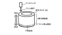
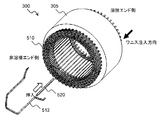
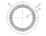
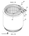
- FIG. 1 It is a figure which shows the outline of the stator manufacturing method of the Example of this invention. It is a perspective view which shows the stator core by which the coil was mounted. It is sectional drawing which looked at the stator core with which the coil was mounted from the welding end side. It is the perspective view which looked at the stator core with which the coil was mounted from the non-welding end side. It is a figure which shows the temperature change in the manufacturing process of a stator. It is a figure which shows the stator core at the time of pouring varnish. It is a figure which shows the stator core at the time of pouring varnish.
- FIG. 1 is a diagram showing an outline of a stator manufacturing method according to an embodiment of the present invention.
- the varnish is injected into the stator core 305 from above (the welding end side shown in FIG. 3) by a dispenser, but the lower portion of the stator core 305 is heated (or the stator core 305). Cooling the upper part of 305), with the temperature difference such that the upper part of the stator core 305 becomes a low temperature (high-speed filling temperature range) and the lower part becomes a high temperature (gelling temperature range), the lower temperature side (upper) Inject varnish from.
- the varnish injected into the slot 310 of the stator core 305 is an example of an insulating resin member, and an insulating resin member having another name may be used.
- the varnish gels and becomes a temperature at which the viscosity becomes high, so that a varnish stop range where the injected varnish does not flow out from the lower part of the stator core 305 is formed.
- the viscosity of the varnish is low, so the injected varnish stays above the varnish stop range and the varnish is injected at a high filling rate. It For this reason, in the high filling range, the bubbles between the stator core 305 and the coil are reduced, the heat generated in the coil is easily released, the vibration of the coil can be suppressed, and the characteristics of the rotating electric machine are stabilized.
- FIG. 2 is a perspective view showing a stator core 305 on which a coil is mounted
- FIG. 3 is a cross-sectional view of the stator core 305 on which a coil is mounted, viewed from the welding end side
- FIG. 4 is a coil.
- FIG. 3 is a perspective view of a stator core 305 on which is mounted as viewed from the non-welding end side.
- the stator (stator) 300 of the rotary electric machine 200 is composed of a cylindrical stator core 305, a stator coil 510 inserted into the stator core 305, and a slot liner 520.
- the stator core 305 is supported inside the housing 205, and on the inner peripheral side of the stator core 305, a rotor (rotor) in which a permanent magnet is embedded is rotatably supported via a gap. ..
- the stator core 305 is formed by stacking a plurality of magnetic bodies (for example, a plurality of electromagnetic steel plates) in the axial direction, and is formed such that the plurality of teeth 307 and the slots 310 are arranged at equal intervals in the circumferential direction.
- Each tooth 307 is integrated with an annular core back. In FIG. 3, all the teeth are not labeled, and only some of the tea scores 307 are designated as a representative.
- a plurality of slots 310 which are continuous in the circumferential direction and are formed on the rotor side, are formed between the adjacent tea scores 307. Slot insulation (not shown) by a slot liner 520 is provided in the slot 310, and coils of a plurality of phases such as U phase, V phase, W phase, and the like which form the stator 300 are mounted.
- the stator coil 510 is housed in the slot 310 of the stator core 305 as shown in FIG.
- the slot 310 is an open slot, and an opening is formed on the inner peripheral side of the stator core 305.
- the circumferential width of the opening formed at the innermost circumference of the slot 310 is substantially equal to or slightly smaller than the coil mounting portion of each slot 310 in which the stator coil 510 is mounted. It is getting smaller.
- a slot liner 520 is arranged in each slot 310.
- the slot liner 520 is an insulating sheet made of, for example, a heat-resistant resin, and has a thickness of about 0.1 to 0.5 mm.
- the gap between the coil in the slot 310 and the stator core 305 is different in the circumferential direction and the radial direction of the stator core 305 in order to improve the insertability of the coil, and one gap is larger than the other gap. Is configured to be. There is a trade-off relationship between the coil insertability determined by the size of the gap and the coil space factor. Further, in this embodiment, the varnish injected into the slot 310 is held by the slot liner 520. That is, the slot liner 520 serves as a varnish holding member.
- the varnish strengthens the insulation between the coils and the insulation between the coils and the stator core 305, fixes the stator coil 510 in the slot 310, and causes vibrations applied to the rotating electric machine 200 and electromagnetic vibrations of the stator coil 510.
- the movement of the stator coil 510 in the slot 310 is suppressed.
- a plurality of segment coils 512 each having a rectangular wire whose outer periphery is covered with an insulating coating and formed in a U shape are separated from each other in two slots 310.
- the end portion is housed so as to be exposed from the slot 310 (that is, the stator core 305), one end portion is adjacent to another segment coil 512, and the other end portion is further adjacent to another segment coil 512. Will be placed.
- the segment coil 512 is arranged in each slot 310 such that the rectangular cross section of the coil is long in the circumferential direction of the stator core 305 and short in the radial direction.
- the ends of the segment coils 512 are connected to each other on the welding end side (the right rear side in FIG. 2) to form a distributed winding stator coil 510 wound around the stator core 305.
- connection terminal 340 and a thermistor 350 are provided on the non-welded end side of the stator 300.
- the connection terminal 340 is provided at an end of a coil having a plurality of phases such as U-phase, V-phase and W-phase, and is connected to a driver of a control circuit (not shown).
- the thermistor 350 measures the temperature of the coil. The coil temperature measured by the thermistor 350 is input to the control circuit.
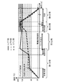
- FIG. 5 is a diagram showing temperature changes in the manufacturing process of the stator 300 of this embodiment, in which the vertical axis represents temperature and the horizontal axis represents elapsed time.
- the welding end side is the upper part and the non-welding end side is the lower part.
- the high-speed filling temperature range depends on the material of the varnish, but is 65° C. to 130° C. in this embodiment.
- the stator core 305 since the stator core 305 is formed of an iron plate, it may be heated by an IH heater having an electrode inserted in a cavity (a portion where the rotor is inserted) in the stator core 305.
- the lower part (non-welding end side) of the stator core 305 is locally heated to the gelation temperature range.
- the gelation temperature range is 130° C. or higher.
- heating may be performed with an IH heater having an electrode adjacent to the lower portion of the stator core 305. Due to this local heating, the temperature of the lower part of the stator core 305 becomes higher than the temperature from the middle part to the upper part (welding end side) of the stator core 305, and a temperature difference is generated in the stator core 305. For this reason, a varnish stop range is formed in the lower part of the stator core 305, and the high filling range is from the middle part to the upper part of the stator core 305 (the above is the first step).
- the method of making a temperature difference is not to locally heat the lower portion of the stator core 305, but to once heat the stator core 305 to a gelling temperature region, and then from the middle portion to the upper portion of the stator core 305 (for example, with a spot cooler). ) After cooling, the stator core 305 may be provided with a temperature difference so that the temperature from the middle portion to the upper portion of the stator core 305 becomes lower than that of the lower portion of the stator core 305 (high-speed filling temperature range).
- the middle part to the upper part of the stator core 305 is in the high-speed filling temperature range, the fluidity of the injected varnish is high and a sufficient amount of varnish can be filled between the coil and the inner wall of the slot 310.
- the filling rate becomes high.
- the axis of the stator core 305 may be tilted from the vertical as shown in FIG. By inclining the stator core 305 and injecting the varnish, the inflow rate of the varnish can be controlled.
- the varnish may be injected while rotating, rotating or swinging the stator core 305.
- the relative positions of the stator core 305 and the dispenser change, and the varnish can be evenly injected in the circumferential direction.
- the varnish can be filled without being biased.
- by injecting the varnish while moving the stator core 305 by rotating, rotating, or swinging it is possible to suppress bubbles from remaining and to fill the varnish with a high filling rate.
- the stator core 305 may be rotated or rotated, but when the varnish is injected with the axis of the stator core 305 vertical, the dispenser may move.
- the entire stator core 305 is heated to the curing temperature range.
- the stator core 305 since the stator core 305 is made of an iron plate, it may be heated by an IH heater having an electrode inserted in a cavity (a portion where the rotor is inserted) in the stator core 305.
- the curing temperature range depends on the material of the varnish, it is 130° C. or higher in this embodiment. Then, by leaving the stator core 305 in the curing temperature range for a long time, the varnish is further cured from the gel state and solidified (the above is the third step).
- the varnish-cured stator core 305 is cooled to room temperature (electric test temperature or lower) (above, fourth step).
- the stator 300 has a portion to prevent adhesion of varnish.
- the varnish can be prevented from flowing out from the lower end of the stator core 305, so that the varnish can be prevented from adhering to the varnish adhesion prohibited area.
- the attachment of varnish is prohibited to the connection terminal 340 and the thermistor 350 provided on the non-welded end side (lower side when varnish is injected) of the stator 300. Since the connection terminal 340 connects the coil and the control circuit, the varnish attached to the surface thereof is insulated. By preventing the varnish from adhering to the connection terminal 340, it is possible to suppress the conduction failure between the rotating electric machine and the control circuit.
- the thermistor 350 measures the temperature of the coil, it needs to be in close contact with the coil. However, since the varnish is interposed between the thermistor 350 and the coil, thermal coupling between the thermistor 350 and the coil is prevented. Become sparse. By not applying varnish to the thermistor 350, the thermal coupling between the thermistor 350 and the coil is tight, allowing the thermistor 350 to measure the correct temperature of the coil.
- the first temperature gelling temperature range
- the inflow rate of the resin material can be controlled.
- the varnish can be uniformly injected in the circumferential direction. In addition, it is possible to suppress bubbles from remaining and to fill the varnish with a high filling rate.
- stator core 305 manufactured by the manufacturing method of the present embodiment, in the slot 310, a region (high filling range) in which the filling rate of the resin member is high is formed on the injection side (from the upper part to the middle part). On the opposite side (lower part), a region having a low filling rate (varnish stop range) is formed.
- high filling range since there are few bubbles between the stator core 305 and the coil, the heat generated in the coil can be easily released, the vibration of the coil can be suppressed, and the characteristics of the rotating electric machine can be stabilized.
- the present invention is not limited to the above-described embodiments, but includes various modifications and equivalent configurations within the spirit of the appended claims.
- the above-described embodiments have been described in detail in order to explain the present invention in an easy-to-understand manner, and the present invention is not necessarily limited to those having all the configurations described.
- part of the configuration of one embodiment may be replaced with the configuration of another embodiment.
- the configuration of another embodiment may be added to the configuration of one embodiment.
- a part of the configuration of each embodiment may be added/deleted/replaced with another configuration.
- stator 305 stator core 307 teeth 307 teeth core 310 slot 340 connection terminal 350 thermistor 510 stator coil 512 segment coil 520 slot liner
Landscapes
- Engineering & Computer Science (AREA)
- Manufacturing & Machinery (AREA)
- Mechanical Engineering (AREA)
- Power Engineering (AREA)
- Manufacture Of Motors, Generators (AREA)
- Insulation, Fastening Of Motor, Generator Windings (AREA)
Abstract
本発明の課題は、スロット内のワニスの充填率を高めて、固定子コアの下部からのワニス流出を抑制することである。 回転電機の固定子の製造方法であって、前記固定子は、コイルと、前記コイルを収納するスロットが形成される固定子コアとを有し、第1の温度では粘度が低く、前記第1の温度より高い第2の温度では粘度が高くなる樹脂部材が注入側から前記スロット内に充填されるものであって、前記製造方法は、前記注入側では前記第1の温度となり、前記注入側の反対側では前記第2の温度となるように、前記固定子コアに温度差をつける第1工程と、前記温度差を維持した状態で、前記樹脂部材を前記注入側から注入する第2工程とを含む。
Description
本発明は、回転電機を構成し、コイルが巻回される固定子の製造方法に関する。
本技術分野の背景技術として、以下の先行技術がある。特許文献1(特開2008-109732号公報)には、前加熱後の第1供給工程では、ステータコアに装着されたコイルのコイルエンドが上下になる姿勢でステータコアを水平に保持し、コイルのうちステータコアの上側端面から突出する上側コイルエンドの上面からワニスを注入し、上側コイルエンドの上から下へ含浸流下するワニスが、コイルのうちステータコアの下側端面から突出する下側コイルエンドの外部に達するより前にゲル化するように供給量を制御しながらワニスを供給する。その後、反転工程では、第1供給工程で最後に供給されたワニスがゲル化する時間以上の間隔をおいてコイルが装着されたステータコアを反転させる。反転工程の後の第2供給工程では、第1供給工程でゲル化が始まった位置付近でゲル化が始まるように供給量を制御してワニスを供給する。その後、コイルに含浸させたワニスを保温硬化させる。
回転電機の固定子において、巻回されるコイルを固定するため、スロット内のワニスのの充填率を高くすることが望まれている。そのため、多量のワニスを注入する必要があるが、固定子コアの下側からワニスが流出すると充填率が低下する。このため、例えば特許文献1に記載された方法では、第1供給工程と第2供給工程とで異なる方向からワニスを注入しているが、第1供給工程と第2供給工程との間に反転工程を含み、作業が繁雑である。
このため、スロット内のワニスの充填率が高い固定子の製造方法が求められている。
本願において開示される発明の代表的な一例を示せば以下の通りである。すなわち、回転電機の固定子の製造方法であって、前記固定子は、コイルと、前記コイルを収納するスロットが形成される固定子コアとを有し、第1の温度では粘度が低く、前記第1の温度より高い第2の温度では粘度が高くなる樹脂部材が注入側から前記スロット内に充填されるものであって、前記製造方法は、前記注入側では前記第1の温度となり、前記注入側の反対側では前記第2の温度となるように、前記固定子コアに温度差をつける第1工程と、前記温度差を維持した状態で、前記樹脂部材を前記注入側から注入する第2工程とを含むことを特徴とする。
本発明の一態様によれば、スロット内のワニスの充填率を高めることができ、固定子コアの下側からのワニスの流下を防止できる。前述した以外の課題、構成及び効果は、以下の実施例の説明によって明らかにされる。
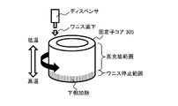
図1は、本発明の実施例の固定子製造方法の概要を示す図である。
本実施例の固定子の製造方法では、固定子コア305に上方(図3に示す溶接エンド側)からディスペンサでワニスを注入するが、固定子コア305の下部を加熱して(又は固定子コア305の上部を冷却して)、固定子コア305の上部が低温(高速充填温度域)、下部が高温(ゲル化温度域)となるような温度差をつけた状態で、低温側(上方)からワニスを注入する。なお、固定子コア305のスロット310に注入されるワニスは絶縁樹脂部材の一例であり、他の名称の絶縁樹脂部材でもよい。
これにより、固定子コア305下部の高温領域は、ワニスがゲル化して、粘度が高くなる温度とするので、注入されたワニスが固定子コア305の下部から流出しないワニス停止範囲を形成する。一方、固定子コア305上部の低温領域から中央部の中温領域は、ワニスの粘度が低い温度とするので、注入されたワニスがワニス停止範囲の上側に停留し、高い充填率でワニスが注入される。このため、高充填範囲では、固定子コア305とコイルとの間の気泡が少なくなり、コイルに生じた熱を放出しやすく、コイルの振動を抑制でき、回転電機の特性が安定する。
次に、本発明の実施例の固定子コア305の構造を説明する。
図2は、コイルが実装された固定子コア305を示す斜視図であり、図3は、コイルが実装された固定子コア305を溶接エンド側から見た断面図であり、図4は、コイルが実装された固定子コア305を非溶接エンド側から見た斜視図である。
回転電機200の固定子(ステータ)300は、円筒状の固定子コア305と、固定子コア305に挿入される固定子コイル510及びスロットライナ520によって構成される。
固定子コア305は、ハウジング205の内部に支持されており、固定子コア305の内周側には、永久磁石が埋め込まれた回転子(ロータ)が空隙を介して回転可能に支持されている。固定子コア305は、複数の磁性体(例えば、複数の電磁鋼板)を軸方向に積層して形成されており、複数のティース307及びスロット310が周方向に等間隔になるように形成されており、それぞれのティース307は環状のコアバックと一体となっている。図3では、ティース全てに符号を付しておらず、代表として一部のティースコア307にのみ符号を付した。隣接するティースコア307の間のそれぞれには、周方向に連続すると共に、回転子側に複数のスロット310が形成されている。スロット310内にはスロットライナ520によるスロット絶縁(図示省略)が設けられ、固定子300を構成するU相、V相、W相などの複数相のコイルが装着されている。
固定子コア305のスロット310には、図2に示すように固定子コイル510が収容される。図2に示す例では、スロット310は開スロットであり、固定子コア305の内周側に開口が形成されている。スロット310の最内周に形成される開口の周方向の幅は、図3に示すように、固定子コイル510が装着される各スロット310のコイル装着部とほぼ同等又はコイル装着部よりも若干小さくなっている。
各スロット310内には、スロットライナ520が配置されている。スロットライナ520は、例えば耐熱樹脂製の絶縁シートであり、厚さは0.1~0.5mm程である。スロット310にスロットライナ520を配設することによって、スロット310に挿通されるコイルの相互間、及びコイルとスロット310の内面との間の絶縁耐圧を向上し、コイルの絶縁被膜が劣化したり傷ついても、必要な絶縁耐圧を保持している。
スロット310内のコイルと固定子コア305との間の隙間は、コイルの挿入性を向上するため、固定子コア305の周方向と径方向で異なり、一方の隙間がもう一方の隙間よりも大きくなるように構成される。隙間の大きさによって決まるコイル挿入性とコイル占積率とはトレードオフの関係にある。また、本実施例では、スロット310に注入されたワニスはスロットライナ520に保持される。すなわち、スロットライナ520がワニス保持部材となる。ワニスによって、コイル間の絶縁及びコイルと固定子コア305との間の絶縁が強化され、スロット310内で固定子コイル510が固定され、回転電機200に加わる振動や固定子コイル510の電磁振動による、スロット310内の固定子コイル510の動きが抑制される。
図2に示すように、本実施例の固定子コア305には、外周は絶縁被膜で覆われている平角線をU字形状に成型した複数のセグメントコイル512が離間した二つのスロット310に、その端部がスロット310(すなわち固定子コア305)から露出するように収納され、一つの端部が他のセグメントコイル512と隣接し、他方の端部がさらに他のセグメントコイル512と隣接して配置される。セグメントコイル512は、各スロット310内で例えばコイルの長方形断面が固定子コア305の周方向について長く、径方向について短くなるように配置されている。セグメントコイル512の端部は、溶接エンド側(図2の右奥側)で互いに接続されて、固定子コア305に巻回される分布巻きの固定子コイル510が構成される。
図4に示すように、固定子300の非溶接エンド側には接続端子340及びサーミスタ350が設けられる。接続端子340は、U相、V相、W相などの複数相のコイルの端部に設けられ、制御回路(図示省略)のドライバに接続される。サーミスタ350は、コイルの温度を測定する。サーミスタ350が測定したコイルの温度は、制御回路に入力される。
図5は、本実施例の固定子300の製造過程における温度変化を示す図であり、縦軸が温度、横軸が経過時間を示す。
なお、本実施例では、固定子コア305の溶接エンド側からワニスを注入するので、溶接エンド側が上部となり、非溶接エンド側が下部となる。
まず、常温から固定子コア305の全体を高速充填温度域まで加熱する。高速充填温度域は、ワニスの材質にもよるが、本実施例では65℃から130℃である。例えば、固定子コア305は鉄板で形成されているので、固定子コア305内の空洞(回転子が挿入される部分)に挿入された電極を有するIHヒータで加熱するとよい。
その後、固定子コア305の下部(非溶接エンド側)を局部的にゲル化温度域まで加熱する。本実施例ではゲル化温度域は130℃以上である。例えば、固定子コア305の下部に近接する電極を有するIHヒータで加熱するとよい。この局部加熱によって、固定子コア305の下部が、固定子コア305の中部から上部(溶接エンド側)より高温となり、固定子コア305に温度差ができる。このため、固定子コア305の下部にワニス停止範囲が形成され、固定子コア305の中部から上部が高充填範囲となる(以上、第1工程)。
なお、温度差をつける方法は、固定子コア305の下部の局部加熱ではなく、固定子コア305を一旦ゲル化温度域まで加熱した後、固定子コア305の中部から上部を(例えばスポットクーラーで)冷却して、固定子コア305の中部から上部が固定子コア305の下部より低温(高速充填温度域)となるように固定子コア305に温度差をつけてもよい。
所定量の温度差(固定子コア305の下部がゲル化温度域、中部から上部が高速充填温度域)を維持した状態で、固定子コア305の上部からスロット310ワニスを注入する。固定子コア305のスロット310内を流下するワニスは、固定子コア305の下部(ゲル化温度域であるワニス停止範囲)に到達すると、ゲル化して、固定子コア305の下端から流出せずに停止し、この領域ではワニスの充填率が低くなる。その後、ワニスの注入を続け、固定子コア305の上端までワニスを注入する(以上、第2工程)。固定子コア305の中部から上部は高速充填温度域となっているので、注入されたワニスの流動性が高く、コイルとスロット310の内壁との間に十分な量のワニスを充填でき、ワニスの充填率が高くなる。
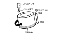
ワニスの注入時に、図6に示すように、固定子コア305の軸を垂直から傾けてもよい。固定子コア305を傾けてワニスを注入することによって、ワニスの流入速度を制御できる。
また、図6、図7に示すように、固定子コア305を回転、回動又は揺動しながらワニスを注入してもよい。固定子コア305を回転又は回動しながらワニスを注入することによって、固定子コア305とディスペンサの相対位置が変化し、周方向に均一にワニスを注入できる。特に、固定子コア305を傾けてワニスを注入する場合、ワニスが偏らずに充填できる。また、回転、回動又は揺動によって固定子コア305を動かしながらワニスを注入することによって、気泡の残留を抑制し、高い充填率でワニスを充填できる。なお、固定子コア305を回転又は回動してもよいが、固定子コア305の軸が垂直の状態でワニスを注入する場合は、ディスペンサが動いてもよい。
所定量のワニスの充填が終了した後、固定子コア305の全体を硬化温度域まで加熱する。例えば、固定子コア305は鉄板で構成されているので、固定子コア305内の空洞(回転子が挿入される部分)に挿入された電極を有するIHヒータで加熱するとよい。硬化温度域は、ワニスの材質にもよるが、本実施例では130℃以上である。そして、固定子コア305を硬化温度域に長時間おくことによって、ワニスはゲル状よりさらに硬化して固体化する(以上、第3工程)。
その後、ワニスが硬化した固定子コア305を常温(電気試験温度以下)に冷却する(以上、第4工程)。
本実施例では、固定子コア305の下部のワニス停止範囲において、ワニスがゲル化し、固定子コア305の下部に停止するので、固定子コア305の下端から流出しない。このため、固定子コア305の中部から上部にかけての高充填範囲におけるワニスの充填率を高めることができる。
また、固定子300にはワニスの付着を防止すべき部分がある。本実施例の固定子の製造方法によると、固定子コア305の下端からのワニスの流出を防止できるので、ワニス付着禁止領域へのワニスの付着を抑制できる。例えば、図4に示すように、固定子300の非溶接エンド側(ワニス注入時の下側)に設けられる接続端子340及びサーミスタ350には、ワニスの付着が禁止される。接続端子340はコイルと制御回路を接続するため、その表面に付着したワニスが絶縁する。接続端子340へのワニスの付着の防止によって、回転電機と制御回路との導通不良を抑制できる。また、サーミスタ350は、コイルの温度を測定するため、コイルに密着している必要があるが、サーミスタ350とコイルの間にワニスが介在することによって、サーミスタ350とコイルとの間の熱結合が疎となる。サーミスタ350にワニスを付着させないことによって、サーミスタ350とコイルとの間の熱結合を密として、サーミスタ350がコイルの正しい温度を測定できるようになる。
以上に説明したように、本実施例の固定子300の製造方法では、注入側(上側となる溶接エンド側)では第1の温度(ゲル化温度域)となり、注入側の反対側(下側となる非溶接エンド側)では第2の温度(高速充填温度域)となるように、固定子コア305に温度差をつける第1工程と、この温度差を維持した状態で、樹脂部材(ワニス)を注入側から注入する第2工程とを含むので、スロット310内のワニスの充填率を高めることができる。また、固定子コア305の下側からのワニスの流出を防止でき、ワニス付着禁止箇所(接続端子340、サーミスタ350など)へのワニスの付着を抑制できる。
また、第2工程において、固定子コア305の軸を垂直から傾けた状態で樹脂部材を注入するので、樹脂材料の流入速度を制御できる。
また、第2工程において、軸を中心に固定子コア305を回転、回動又は揺動させながら樹脂部材を注入するので、周方向に均一にワニスを注入できる。また、気泡の残留を抑制し、高い充填率でワニスを充填できる。
また、本実施例の製造方法によって製造された固定子コア305は、スロット310内において、注入側(上部から中部)では樹脂部材の充填率が高い領域(高充填範囲)が形成され、注入側の反対側(下部)では充填率が低い領域(ワニス停止範囲)が形成される。高充填範囲では、固定子コア305とコイルとの間の気泡が少ないので、コイルに生じた熱を放出しやすく、コイルの振動を抑制でき、回転電機の特性を安定化できる。
なお、本発明は前述した実施例に限定されるものではなく、添付した特許請求の範囲の趣旨内における様々な変形例及び同等の構成が含まれる。例えば、前述した実施例は本発明を分かりやすく説明するために詳細に説明したものであり、必ずしも説明した全ての構成を備えるものに本発明は限定されない。また、ある実施例の構成の一部を他の実施例の構成に置き換えてもよい。また、ある実施例の構成に他の実施例の構成を加えてもよい。また、各実施例の構成の一部について、他の構成の追加・削除・置換をしてもよい。
200 回転電機
205 ハウジング
300 固定子
305 固定子コア
307 ティース
307 ティースコア
310 スロット
340 接続端子
350 サーミスタ
510 固定子コイル
512 セグメントコイル
520 スロットライナ
205 ハウジング
300 固定子
305 固定子コア
307 ティース
307 ティースコア
310 スロット
340 接続端子
350 サーミスタ
510 固定子コイル
512 セグメントコイル
520 スロットライナ
Claims (4)
- 回転電機の固定子の製造方法であって、
前記固定子は、コイルと、前記コイルを収納するスロットが形成される固定子コアとを有し、
第1の温度では粘度が低く、前記第1の温度より高い第2の温度では粘度が高くなる樹脂部材が注入側から前記スロット内に充填されるものであって、
前記製造方法は、
前記注入側では前記第1の温度となり、前記注入側の反対側では前記第2の温度となるように、前記固定子コアに温度差をつける第1工程と、
前記温度差を維持した状態で、前記樹脂部材を前記注入側から注入する第2工程とを含むことを特徴とする製造方法。 - 請求項1に記載の製造方法であって、
前記第2工程において、前記固定子コアの軸を垂直から傾けた状態で前記樹脂部材を注入することを特徴とする製造方法。 - 請求項1に記載の製造方法であって、
前記第2工程において、軸を中心に前記固定子コアを回転、回動又は揺動させながら前記樹脂部材を注入することを特徴とする製造方法。 - 請求項1から3のいずれか一つに記載の製造方法によって製造された固定子コアであって、
前記スロット内において、前記注入側では前記樹脂部材の充填率が高い領域が形成され、前記注入側の反対側では充填率が低い領域が形成されることを特徴とする固定子コア。
Priority Applications (3)
| Application Number | Priority Date | Filing Date | Title |
|---|---|---|---|
| US17/424,956 US11843292B2 (en) | 2019-02-07 | 2020-01-08 | Method for manufacturing stator |
| JP2020571046A JP7163421B2 (ja) | 2019-02-07 | 2020-01-08 | 固定子の製造方法及び固定子コア |
| CN202080011559.8A CN113366744B (zh) | 2019-02-07 | 2020-01-08 | 定子的制造方法和定子芯体 |
Applications Claiming Priority (2)
| Application Number | Priority Date | Filing Date | Title |
|---|---|---|---|
| JP2019020331 | 2019-02-07 | ||
| JP2019-020331 | 2019-02-07 |
Publications (1)
| Publication Number | Publication Date |
|---|---|
| WO2020162088A1 true WO2020162088A1 (ja) | 2020-08-13 |
Family
ID=71947595
Family Applications (1)
| Application Number | Title | Priority Date | Filing Date |
|---|---|---|---|
| PCT/JP2020/000230 Ceased WO2020162088A1 (ja) | 2019-02-07 | 2020-01-08 | 固定子の製造方法及び固定子コア |
Country Status (4)
| Country | Link |
|---|---|
| US (1) | US11843292B2 (ja) |
| JP (1) | JP7163421B2 (ja) |
| CN (1) | CN113366744B (ja) |
| WO (1) | WO2020162088A1 (ja) |
Cited By (2)
| Publication number | Priority date | Publication date | Assignee | Title |
|---|---|---|---|---|
| WO2022128632A1 (en) * | 2020-12-14 | 2022-06-23 | Valeo Siemens Eautomotive Germany Gmbh | Method for impregnating rotor coils |
| DE102022128506A1 (de) * | 2022-10-27 | 2024-05-02 | Audi Aktiengesellschaft | Verfahren zum Imprägnieren wenigstens einer Drahtwicklung eines Bauteils |
Families Citing this family (6)
| Publication number | Priority date | Publication date | Assignee | Title |
|---|---|---|---|---|
| US12212197B2 (en) | 2022-09-28 | 2025-01-28 | Ford Global Technologies, Llc | Varnish injector for motor |
| US12573925B2 (en) * | 2022-10-19 | 2026-03-10 | Ford Global Technologies, Llc | Assembly for varnish injection of a vehicle motor |
| US12328042B2 (en) | 2023-01-05 | 2025-06-10 | Ford Global Technologies, Llc | Varnish application system for electric motor |
| US12562607B2 (en) | 2023-01-18 | 2026-02-24 | Ford Global Technologies, Llc | Laminate for stator core with fluid containment feature |
| US12537427B2 (en) | 2023-04-04 | 2026-01-27 | Ford Global Technologies, Llc | Method of varnish trickling to improve emachine durability |
| DE102024107995A1 (de) | 2024-03-20 | 2025-09-25 | Audi Aktiengesellschaft | Verfahren zum Herstellen eines Bauteils für eine elektrische Maschine sowie entsprechende Vorrichtung zur Herstellung des Bauteils |
Citations (8)
| Publication number | Priority date | Publication date | Assignee | Title |
|---|---|---|---|---|
| JPS59139839A (ja) * | 1983-01-26 | 1984-08-10 | Mitsubishi Electric Corp | 樹脂含浸成形コイルの製造方法 |
| JPH06209548A (ja) * | 1992-10-13 | 1994-07-26 | Reliance Electric Co | 電磁コイルのコーティング装置及び方法 |
| JPH10257726A (ja) * | 1997-03-07 | 1998-09-25 | Nishishiba Electric Co Ltd | 回転電機および回転電機巻線の絶縁方法 |
| JP2011062036A (ja) * | 2009-09-14 | 2011-03-24 | Honda Motor Co Ltd | ワニス処理方法 |
| JP2011139588A (ja) * | 2009-12-28 | 2011-07-14 | Hitachi Automotive Systems Ltd | 回転電機およびその製造方法 |
| JP2013192357A (ja) * | 2012-03-14 | 2013-09-26 | Mitsubishi Electric Corp | 電気機器の巻線体及びその製造方法 |
| JP2016127781A (ja) * | 2015-01-08 | 2016-07-11 | 三菱電機株式会社 | 電気機器コイルの製造方法及びワニス滴下含浸装置並びに回転電機の製造方法 |
| JP2019170105A (ja) * | 2018-03-26 | 2019-10-03 | アイシン・エィ・ダブリュ株式会社 | 電機子の製造方法および電機子の製造装置 |
Family Cites Families (10)
| Publication number | Priority date | Publication date | Assignee | Title |
|---|---|---|---|---|
| JPS5332302A (en) | 1976-09-06 | 1978-03-27 | Toshiba Corp | Varnish impregnation for stator in electric rotary machine |
| JPS62138038A (ja) * | 1985-12-12 | 1987-06-20 | Toshiba Chem Corp | 滴下含浸処理方法 |
| JP3564299B2 (ja) * | 1998-07-10 | 2004-09-08 | 株式会社東芝 | アウタロータ形モータのステータ |
| JP4872594B2 (ja) | 2006-10-23 | 2012-02-08 | トヨタ自動車株式会社 | ワニス処理方法 |
| JP5804095B2 (ja) * | 2013-01-22 | 2015-11-04 | トヨタ自動車株式会社 | ステータ及びステータの製造方法 |
| JP5667243B2 (ja) * | 2013-06-11 | 2015-02-12 | ファナック株式会社 | 樹脂成形部を有する電動機ステータの製造方法、電動機ステータおよび電動機 |
| JP2015126645A (ja) | 2013-12-27 | 2015-07-06 | 日立オートモティブシステムズ株式会社 | 電動機械の固定子の加熱方法、及び加熱装置 |
| JP6202173B2 (ja) * | 2016-01-27 | 2017-09-27 | ダイキン工業株式会社 | モータ |
| JP6833532B2 (ja) * | 2017-01-30 | 2021-02-24 | 本田技研工業株式会社 | スロットコイル、回転電機のステータ、及び回転電機のステータの製造方法 |
| JP6805093B2 (ja) * | 2017-02-13 | 2020-12-23 | 株式会社三井ハイテック | 固定子積層鉄心の製造方法及び固定子積層鉄心 |
-
2020
- 2020-01-08 CN CN202080011559.8A patent/CN113366744B/zh active Active
- 2020-01-08 US US17/424,956 patent/US11843292B2/en active Active
- 2020-01-08 JP JP2020571046A patent/JP7163421B2/ja active Active
- 2020-01-08 WO PCT/JP2020/000230 patent/WO2020162088A1/ja not_active Ceased
Patent Citations (8)
| Publication number | Priority date | Publication date | Assignee | Title |
|---|---|---|---|---|
| JPS59139839A (ja) * | 1983-01-26 | 1984-08-10 | Mitsubishi Electric Corp | 樹脂含浸成形コイルの製造方法 |
| JPH06209548A (ja) * | 1992-10-13 | 1994-07-26 | Reliance Electric Co | 電磁コイルのコーティング装置及び方法 |
| JPH10257726A (ja) * | 1997-03-07 | 1998-09-25 | Nishishiba Electric Co Ltd | 回転電機および回転電機巻線の絶縁方法 |
| JP2011062036A (ja) * | 2009-09-14 | 2011-03-24 | Honda Motor Co Ltd | ワニス処理方法 |
| JP2011139588A (ja) * | 2009-12-28 | 2011-07-14 | Hitachi Automotive Systems Ltd | 回転電機およびその製造方法 |
| JP2013192357A (ja) * | 2012-03-14 | 2013-09-26 | Mitsubishi Electric Corp | 電気機器の巻線体及びその製造方法 |
| JP2016127781A (ja) * | 2015-01-08 | 2016-07-11 | 三菱電機株式会社 | 電気機器コイルの製造方法及びワニス滴下含浸装置並びに回転電機の製造方法 |
| JP2019170105A (ja) * | 2018-03-26 | 2019-10-03 | アイシン・エィ・ダブリュ株式会社 | 電機子の製造方法および電機子の製造装置 |
Cited By (2)
| Publication number | Priority date | Publication date | Assignee | Title |
|---|---|---|---|---|
| WO2022128632A1 (en) * | 2020-12-14 | 2022-06-23 | Valeo Siemens Eautomotive Germany Gmbh | Method for impregnating rotor coils |
| DE102022128506A1 (de) * | 2022-10-27 | 2024-05-02 | Audi Aktiengesellschaft | Verfahren zum Imprägnieren wenigstens einer Drahtwicklung eines Bauteils |
Also Published As
| Publication number | Publication date |
|---|---|
| JPWO2020162088A1 (ja) | 2021-09-30 |
| US11843292B2 (en) | 2023-12-12 |
| CN113366744A (zh) | 2021-09-07 |
| CN113366744B (zh) | 2024-12-24 |
| JP7163421B2 (ja) | 2022-10-31 |
| US20220094248A1 (en) | 2022-03-24 |
Similar Documents
| Publication | Publication Date | Title |
|---|---|---|
| JP7163421B2 (ja) | 固定子の製造方法及び固定子コア | |
| US10763730B2 (en) | Insulating resin coating method and stator | |
| US10536061B2 (en) | Method for manufacturing stator of rotary electric machine | |
| JP2015154514A (ja) | 樹脂ケーシングの成型方法およびモータ | |
| JP7607201B2 (ja) | モールドモータの製造方法及びモールドモータ | |
| JP7369909B2 (ja) | 固定子構成体、電動機 | |
| JP2015136201A (ja) | モータ及びステータの製造方法 | |
| JPWO2021124972A5 (ja) | ||
| JP2010142075A (ja) | 固定子構造及び固定子製造方法 | |
| JP5868913B2 (ja) | ステータワーク加熱装置、ステータワーク加熱方法及びステータコイル製造方法 | |
| JP2019097371A (ja) | 静止部、モータ、およびモータの静止部の製造方法 | |
| JP2015033299A (ja) | ステータコイルの冷却構造及びステータコイルの冷却構造の製造方法 | |
| WO2019189529A1 (ja) | モータ | |
| JP2019170105A (ja) | 電機子の製造方法および電機子の製造装置 | |
| CN114026768B (zh) | 绝缘架及电动机 | |
| JP7133494B2 (ja) | ステータの製造方法、回転電機の製造方法、及び回転電機 | |
| TWI841653B (zh) | 電樞的線圈架構造 | |
| JP7426557B2 (ja) | モールドモータ | |
| JP2015126645A (ja) | 電動機械の固定子の加熱方法、及び加熱装置 | |
| JP6969407B2 (ja) | コイル皮膜形成装置 | |
| JP2020092521A (ja) | 樹脂の充填方法 | |
| JP7661432B2 (ja) | 回転電機の製造方法 | |
| JP7823554B2 (ja) | 回転電機用ロータの製造方法 | |
| JP2025005459A (ja) | 電機子、回転電機、電機子の製造方法および回転電機の製造方法 | |
| JP2023153077A (ja) | ステータの製造方法及びステータ |
Legal Events
| Date | Code | Title | Description |
|---|---|---|---|
| 121 | Ep: the epo has been informed by wipo that ep was designated in this application |
Ref document number: 20752263 Country of ref document: EP Kind code of ref document: A1 |
|
| ENP | Entry into the national phase |
Ref document number: 2020571046 Country of ref document: JP Kind code of ref document: A |
|
| NENP | Non-entry into the national phase |
Ref country code: DE |
|
| 122 | Ep: pct application non-entry in european phase |
Ref document number: 20752263 Country of ref document: EP Kind code of ref document: A1 |