WO2020158627A1 - 光学部品、それを用いた画像表示装置およびヘッドアップディスプレイ - Google Patents
光学部品、それを用いた画像表示装置およびヘッドアップディスプレイ Download PDFInfo
- Publication number
- WO2020158627A1 WO2020158627A1 PCT/JP2020/002599 JP2020002599W WO2020158627A1 WO 2020158627 A1 WO2020158627 A1 WO 2020158627A1 JP 2020002599 W JP2020002599 W JP 2020002599W WO 2020158627 A1 WO2020158627 A1 WO 2020158627A1
- Authority
- WO
- WIPO (PCT)
- Prior art keywords
- main surface
- optical component
- display device
- image display
- optical
- Prior art date
- Legal status (The legal status is an assumption and is not a legal conclusion. Google has not performed a legal analysis and makes no representation as to the accuracy of the status listed.)
- Ceased
Links
Images


Classifications
-
- G—PHYSICS
- G02—OPTICS
- G02B—OPTICAL ELEMENTS, SYSTEMS OR APPARATUS
- G02B1/00—Optical elements characterised by the material of which they are made; Optical coatings for optical elements
- G02B1/02—Optical elements characterised by the material of which they are made; Optical coatings for optical elements made of crystals, e.g. rock-salt, semi-conductors
-
- G—PHYSICS
- G02—OPTICS
- G02B—OPTICAL ELEMENTS, SYSTEMS OR APPARATUS
- G02B27/00—Optical systems or apparatus not provided for by any of the groups G02B1/00 - G02B26/00, G02B30/00
- G02B27/01—Head-up displays
- G02B27/0101—Head-up displays characterised by optical features
-
- G—PHYSICS
- G02—OPTICS
- G02B—OPTICAL ELEMENTS, SYSTEMS OR APPARATUS
- G02B5/00—Optical elements other than lenses
- G02B5/20—Filters
- G02B5/22—Absorbing filters
-
- G—PHYSICS
- G02—OPTICS
- G02B—OPTICAL ELEMENTS, SYSTEMS OR APPARATUS
- G02B5/00—Optical elements other than lenses
- G02B5/30—Polarising elements
-
- G—PHYSICS
- G02—OPTICS
- G02B—OPTICAL ELEMENTS, SYSTEMS OR APPARATUS
- G02B5/00—Optical elements other than lenses
- G02B5/30—Polarising elements
- G02B5/3025—Polarisers, i.e. arrangements capable of producing a definite output polarisation state from an unpolarised input state
- G02B5/3033—Polarisers, i.e. arrangements capable of producing a definite output polarisation state from an unpolarised input state in the form of a thin sheet or foil, e.g. Polaroid
Definitions
- the present invention relates to an optical component used in an optical device such as an image display device, an image display device using the optical component, and a head-up display.
- An image display device such as a projector device (PJ device) and a head-up display device (HUD device) uses image information displayed on an image forming unit such as a liquid crystal panel, a light source and various optical elements to display a wall, a screen, It is a device that illuminates a window or the like to allow the user to visually recognize image information.
- an image display device is equipped with various optical components. Examples of the optical component include a lens, a fluorescent plate on which a fluorescent substance is arranged, a polarizing plate, and a sealing glass that seals liquid crystal.
- Patent Document 1 describes a vehicle-mounted HUD device, which includes a display element having a liquid crystal cell between an incident-side polarization member and an emission-side polarization member, and a light source that irradiates the display element with light. It is described that a display image transmitted through the display element is projected and displayed on a display member provided in the front visual field of the driver.
- the vehicle-mounted HUD device described in Patent Document 1 includes a heat transfer member (quartz heat dissipation plate) that transmits the display image and is in contact with the emission side polarization member in the optical path of the display image between the liquid crystal cell and the display member; A holding member made of a material for holding the heat transfer member.
- the optical component according to the present disclosure includes a substrate that includes sapphire and has a first main surface and a second main surface that face each other.
- the inclination of the first main surface and the second main surface is 15° or less with respect to the c-plane of sapphire.
- the heat dissipation portion is provided on at least one of the first main surface and the second main surface.
- the image display device includes a light source and the above-mentioned optical component located on the optical path of light emitted from the light source. Further, the head-up display according to the present disclosure includes this image display device and a display unit on which an image is displayed.
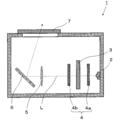
- FIG. 3 is a schematic diagram showing an image display device using an optical component according to an embodiment of the present disclosure.
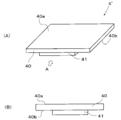
- A is an explanatory view for explaining an optical component according to an embodiment of the present disclosure
- B shows an optical component according to an embodiment of the present disclosure from a direction of an arrow A shown in (A).
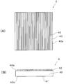
- FIG. It is explanatory drawing which shows the crystal structure of sapphire. It is explanatory drawing in case an optical component which concerns on one Embodiment of this indication is a polarizing plate, (A) shows a top view and (B) shows a side view. It is explanatory drawing in case the optical component which concerns on other embodiment of this indication is a polarizing plate, (A) shows a top view, (B) shows sectional drawing.
- optical component means a functional component that controls the intensity, color (wavelength), phase, polarization, or direction of light of incident light.
- optical component include a fluorescent plate, a wavelength filter, a wavelength plate, a polarizing plate, a mirror, and a lens.
- the optical component of the present disclosure includes a substrate that includes sapphire and has a first main surface and a second main surface that face each other.
- the inclination of the first main surface and the second main surface with respect to the c-plane of sapphire is 15° or less.
- the heat dissipation portion is provided on at least one of the first main surface and the second main surface.
- the inclinations of the first principal surface and the second principal surface are relatively small at 15° or less with respect to the c-plane of sapphire, and the thickness direction of the substrate and the c-axis direction of sapphire substantially coincide with each other.
- sapphire Since sapphire has a high thermal conductivity in the direction parallel to the c-axis, it is advantageous for heat transfer in the thickness direction of the substrate. Further, by providing the heat dissipation portion on at least one of the first main surface and the second main surface, it is possible to efficiently dissipate heat in the thickness direction of the substrate, which is the direction in which the thermal conductivity is high.
- FIG. 1 shows an image display device (HUD device) 1 including an optical component according to an embodiment of the present disclosure.
- the image display device 1 shown in FIG. 1 includes a light source 2, an image forming unit 3, a polarizing plate 4, a lens 5, a mirror 6, and an exit window 7.
- the image forming unit 3, the polarizing plate 4, and the lens 5 correspond to the optical components in this specification.
- the exit window 7 has a function as an optical filter that cuts infrared light, for example, it corresponds to an optical component.
- at least one is the optical component 4'according to the embodiment of the present disclosure. Details of the image display device (HUD device) 1 will be described later.
- the optical component 4′ includes sapphire and includes a substrate 40 having a first major surface 40a and a second major surface 40b that face each other, as shown in FIG.
- Examples of the substrate 40 containing sapphire include a sapphire substrate.
- Sapphire is a single crystal of aluminum oxide (Al 2 O 3 ). Sapphire has excellent heat resistance, thermal conductivity, and heat dissipation, and also has the property of suppressing temperature rise.
- the thickness of the substrate 40 is not limited.
- the substrate 40 may have a thickness of about 0.1 mm or more and 15 mm or less in order to satisfy the mechanical strength and the heat dissipation in a well-balanced manner.
- FIG. 3 shows the crystal structure of sapphire.
- sapphire has a hexagonal crystal structure, and c-plane, m-plane, a-plane and r-plane exist as typical crystal planes.
- the axes perpendicular to these planes are called the c-axis, m-axis, a-axis and r-axis, respectively.
- the inclination of the first principal surface 40a and the second principal surface 40b is 15° or less with respect to the c-plane of sapphire means, for example, when the substrate 40 is obtained by processing a sapphire ingot, the first principal surface of the substrate 40. It is shown that 40a and the second major surface 40b are substantially parallel to the c-plane shown in FIG. That is, the first major surface 40a and the second major surface 40b of the substrate 40 do not necessarily have to be processed in parallel with the c-plane shown in FIG. 3A, and the angle formed with the c-plane of sapphire is 15° or less. May be the first main surface 40a and the second main surface 40b of the substrate 40.
- the inclination of the first main surface 40a and the second main surface 40b may be 5° or less with respect to the c-plane of sapphire.
- the angle formed by the plane approximate to the curved surface and the c-plane is 15° or less in the cross-sectional view of the substrate 40 in the thickness direction.
- the approximating plane is a least-squares plane obtained by the least-squares method, for example.
- the heat dissipation portion 41 is provided on the second main surface 40b of the substrate 40.
- the heat radiating unit 41 is used to efficiently dissipate heat generated when the device 1 is operated, heat received from the outside of the device 1 and the like in the HUD device 1 and the like including the optical component 4 ′.
- the thermal conductivity of sapphire is higher in the direction parallel to the c-axis than in the direction orthogonal to the c-axis. Therefore, heat is easily transferred in the c-axis direction (thickness direction of the substrate 40), and is radiated through the heat dissipation portion 41 provided on at least one of the first main surface 40a and the second main surface 40b.
- the form of the heat dissipation part 41 is not particularly limited.
- the portion of the substrate 40 that has a smaller thermal resistance than the portion other than the heat radiation portion 41 or is cooled by an external cooling mechanism to promote heat radiation is referred to as a “heat radiation portion”.
- a heat radiation portion is a portion having a larger surface area per unit projected area, a portion having a larger surface roughness, a portion having a higher thermal conductivity, or a portion exposed to cooling air from the outside than the portion other than the heat radiation portion 41.
- a portion of the main surface on which a metal material (metal foil or the like) is arranged may be the heat dissipation portion 41, and at least a part of the main surface can be easily exposed to the wind or easily contacted with air, or a processed portion can be radiated. It may be part 41. Alternatively, in order to increase the surface area or surface roughness, fine lines or irregularities may be formed on the main surface to serve as the heat dissipation portion 41.
- Such a heat dissipation portion 41 may be arranged in the optical path, and preferably has a size and shape that does not reduce the transmittance of light from the light source 2, for example, a size and shape that reduces the reflectance of incident light. ..
- a region in which the thermal conductivity of sapphire itself is improved by replacing part of oxygen in sapphire with nitrogen may be used as the heat dissipation portion 41.
- the aluminum nitride in which a part of oxygen of sapphire is replaced with nitrogen include aluminum nitride and aluminum oxynitride.
- Aluminum oxynitride is a compound or solid solution containing oxygen, nitrogen and aluminum as constituent elements.
- aluminum nitride and aluminum oxynitride have higher thermal conductivity than aluminum oxide, they can be used as the heat dissipation portion 41.
- Aluminum nitride and aluminum oxynitride may be crystalline or amorphous, and the higher the crystallinity, the higher the thermal conductivity. Further, since the single crystal has no grain boundary, it has a high light transmittance and can be arranged on the optical path. If the heat dissipation portion 41 is made of a material that does not easily transmit light, such as metal, or has a shape that does not easily transmit light, the heat dissipation portion 41 may be arranged in a region that does not obstruct the optical path.
- a functional portion is provided on at least one of the first main surface 40a and the second main surface 40b of the substrate 40 that faces the heat dissipation portion 41.
- the “functional part” means a function of controlling or reinforcing the intensity, color, phase, polarization or direction of light of incident light, a reinforcing portion, a function of refracting incident light, and the like.
- Specific examples of the functional unit include an optical filter that transmits or absorbs a part of incident light, an antireflection film, a reflective film, a phosphor, and a color wheel. Only one kind of such a functional part may be provided on at least one of the first main surface 40a and the second main surface 40b, or two or more kinds thereof may be provided.
- the optical filter examples include an optical filter (IR cut film or the like) that transmits or absorbs light of a specific wavelength range, an optical filter (liquid crystal, polarizer, or the like) that transmits or absorbs light of a specific polarization direction, and the like.
- the reflection film also includes a dichroic film that transmits light of a specific wavelength and reflects light of another wavelength.
- the heat dissipation part 41 is preferably provided on the second main surface 40b.
- the optical component 4' heats in the functional part.
- the functional portion and the heat radiating portion 41 are provided on the opposing main surfaces, it is easy to shorten the distance between the functional portion and the heat radiating portion 41.
- the first main surface 40a and the second main surface 40b are substantially parallel to the c-plane, that is, if the thickness direction of the substrate 40 is substantially parallel to the c-axis, heat is easily transferred in the thickness direction of the substrate 40, and the heat dissipation portion 41 is formed. It is easy to radiate heat through.
- the functional part having the largest heat generation amount (may be referred to as the first functional part) is formed on the first main surface 40a.
- the heat dissipation portion 41 may be provided on the second main surface 40b. If the first main surface 40a and the second main surface 40b are substantially parallel to the c-plane, that is, if the thickness direction of the substrate 40 is substantially parallel to the c-axis, heat is easily transferred in the thickness direction of the substrate 40 and the first functional portion Heat is likely to be dissipated through the heat dissipation portion 41.
- the functional unit will be specifically described by taking as an example the case where the optical component 4 ′ according to the embodiment is the polarizing plate 4.
- the polarizing plate 4 is provided on the substrate 40, the polarizer 42 formed on the first main surface 40 a of the substrate 40, and the second main surface 40 b of the substrate 40. And a heat dissipation part 41.
- the polarizer 42 has, for example, a structure in which a plurality of thin metal wires are aligned with a gap.
- the thin metal wire is not particularly limited as long as it is formed of a metal, and examples of the metal include aluminum, copper, gold, silver and alloys thereof.
- the thin metal wire is formed, for example, by the following method.
- the first main surface 40a of the substrate 40 is coated with a metal film by a film forming method such as a vapor deposition method or a sputtering method.
- a resist film is applied on the surface of the metal film, exposed and developed to form a resist pattern.
- the metal film is etched using an etchant into stripes at regular intervals. Then, by removing the resist pattern and washing it, the metal thin wire can be formed on the first main surface 40 a of the substrate 40.
- the thin metal wire has a thickness of, for example, 50 nm or more and 500 nm or less, and a width of 30 nm or more and 150 nm or less.
- the width of the gap between the metal thin wires is usually 60 nm or more and 300 nm or less.
- the heat dissipation portion 41 (first form) is formed on the second main surface 40b. It may have been done.
- the surface roughness (for example, the arithmetic mean roughness Ra) of part or all of the second main surface 40b may be larger than the surface roughness of the first main surface 40a.
- the heat dissipation portion 41' may be on the optical path (including the central portion of the second main surface 40b in plan view). Even if the surface roughness is slightly increased, there is no problem in practical use as long as it satisfies the optical characteristics (eg, transmittance) of the optical component 4'.
- an opaque separate body such as a metal member may be attached to the substrate 40 as the heat radiating portion 41' (second form). An example thereof is shown in FIG.
- a frame is attached so that a part thereof is in contact with the outer periphery of the second main surface 40b.
- this frame acts as a heat dissipation portion 41', and the heat dissipation portion 41' is located outside the optical path.
- the heat generated in the functional portion located on the first main surface 40a is efficiently conducted to the second main surface 40b side in the thickness direction of the substrate 40 and radiated to the outside. This heat dissipation is further promoted by the heat dissipation portion 41'.
- the heat dissipation portion 41' may be in contact with the outer peripheral portion of the second main surface 40b to the side surface of the substrate as shown in FIG. 5, or may be in contact with the outer periphery of the first main surface 40a.
- the optical component 4 ′ according to the embodiment can also be used as the lens 5.
- the substrate 40 may be processed into a concave lens or a convex lens.
- the heat dissipation portion 41 is provided, for example, outside the optical path of the second main surface 40b so as not to obstruct the optical path.
- the optical component 4 ′ according to the embodiment is used as a member of the image display device 1 together with the light source 2, for example.
- the polarizing plate 4 and the lens 5 correspond to the optical component 4'according to the embodiment.
- the emission window 7 includes an IR cut film as a functional part
- the emission window 7 corresponds to the optical component 4'according to the embodiment.
- the image display device 1 according to an embodiment of the present disclosure will be specifically described by taking the case of the HUD device 1 shown in FIG. 1 as an example.
- the HUD device 1 shown in FIG. 1 includes the light source 2, the image forming unit 3, the polarizing plate 4, the lens 5, the mirror 6, and the exit window 7.
- Two types of polarizing plate 4 are used: an incident side polarizing plate 4a and an emitting side polarizing plate 4b.
- an incident side polarization plate 4a, an image forming unit 3, an emission side polarization plate 4b, a lens 5 and a mirror 6 are arranged in order from the side closer to the light source 2.
- the emission optical path L of the image light including the emission light from the light source 2 is indicated by a dashed-dotted arrow.
- the incident-side polarization plate 4 a of the polarization plates 4 is used to polarize the light from the light source 2 and make it incident on the image forming unit 3.
- the polarizer 42 is made of a material having a higher thermal conductivity than sapphire (for example, aluminum, copper, etc.), so that the heat dissipation can be further improved.
- the image forming unit 3 include a liquid crystal panel such as a twisted nematic liquid crystal (TN liquid crystal).
- the emission-side polarization plate 4b of the polarization plate 4 is used to block the polarization of the image light emitted from the image forming unit 3 in a direction unnecessary for image display. Also for the emission side polarization plate 4b, heat dissipation can be further improved by forming the polarizer 42 with a material having a higher thermal conductivity than sapphire (for example, aluminum, copper, etc.).
- the combination of the polarization directions of the incident side polarization plate 4a and the emission side polarization plate 4b is appropriately set depending on the type of the image forming unit 3. For example, when a TN liquid crystal is used as the image forming unit 3, the incident side polarization plate 4a and the emission side polarization plate 4b are arranged by rotating the polarization direction by 90°.
- the image light transmitted through the exit side polarizing plate 4b is incident on the lens 5.
- the HUD device 1 includes the lens 5, the image light can be expanded.
- the lens 5 is a convex lens.
- the image light magnified by the lens 5 is reflected by the mirror 6 and is projected through the exit window 7 onto the display unit (screen) outside the HUD device 1.
- Examples of the display unit include glass and a screen.
- the HUD device 1 is used as the vehicle-mounted HUD device 1, examples of the display unit include a windshield, a rear glass, and a window of an automobile.
- the inclinations of the first main surface 40 a and the second main surface 40 b are relatively small at 15° or less with respect to the c-plane of sapphire, and the thickness direction of the substrate 40 is The c-axis direction of sapphire almost coincides. Since sapphire has a high thermal conductivity in the direction parallel to the c-axis, it is advantageous for heat transfer in the thickness direction of the substrate. Further, by providing the heat dissipation portion 41 on at least one of the first main surface 40a and the second main surface 40b, heat can be efficiently dissipated in the thickness direction of the substrate 40, which is the direction in which the thermal conductivity is high.
- the image display device 1 including the optical component 4' can be used even under a relatively high temperature condition due to the excellent heat dissipation of the optical component 4'.
- Examples of the image display device 1 used under such high temperature conditions include an image display device 1 mounted on a moving body such as a vehicle, a railroad, a ship, and an aircraft, and an image display device 1 used outdoors.
- a vehicle-mounted HUD device 1 is exemplified.
- the optical component of the present disclosure is not limited to the optical component 4'according to the above embodiment.
- the substrate 40 used for the optical component 4'according to the embodiment has a rectangular shape.
- the shape of the substrate 40 used for the optical component of the present disclosure is appropriately set depending on, for example, the application, and for example, a polygonal shape other than a quadrangular shape such as a triangular shape, a pentagonal shape, and a hexagonal shape, a circular shape, an oval shape, or the like. Are listed.
- the functional unit is the polarizer 42
- the functional unit may be appropriately set depending on the application of the optical component such as an optical filter other than the polarizer 42, an antireflection film, a reflective film, a phosphor, or the like.
- the image display device 1 according to the present disclosure is not limited to the HUD device 1 shown in FIG.
- the image display device 1 according to the present disclosure may include a blower unit capable of blowing air to the optical component in order to cool the optical component used as a member.
- the optical component of the present disclosure may include a blower unit capable of blowing air to the main surface on which the heat dissipation unit 41 is provided.
- the air blower is provided so as to blow air to the second main surface 40b.
- the air blower includes, for example, a sirocco fan and a propeller fan.
- the sirocco fan has a strong force to send out air, and the direction of the fan's rotation axis and the blowing direction are different. Therefore, the degree of freedom of the installation place is increased, and a sirocco fan may be used.
- a blower which is a cylindrical body, may be placed on the optical path for use.
- a wind blowing portion is provided on the inner peripheral surface of the tubular body having the internal flow passage, and the wind light is disposed so that the image light passes through the hollow portion of the tubular body.
- the wind emitted from the opening is efficiently blown to the main surface of the polarizing plate 4, and the main surface provided with the heat dissipation portion 41 can be efficiently cooled without obstructing the optical path of the image light.
- the polarizing plate 4 has been described as an example, optical components other than the polarizing plate 4 can be efficiently cooled in the same manner.
- the image display device is not limited to the image display device 1 described above.
- the light passing through the optical path is not limited to light having a two-dimensional cross section, and may be laser light or the like.
- the optical component in this case include a fluorescent plate for laser light and a color wheel.
- the degree of freedom in designing the position and shape of the heat dissipation portion 41 is improved. Is easy.
- Image display device HUD device 2 light source 3 image forming unit 4 polarizing plate 4'optical component 4a incident side polarizing plate 4b emitting side polarizing plate 40 substrate 40a first main surface 40b second main surface 41, 41' heat radiating unit 42 polarizer
Landscapes
- Physics & Mathematics (AREA)
- General Physics & Mathematics (AREA)
- Optics & Photonics (AREA)
- Chemical & Material Sciences (AREA)
- Crystallography & Structural Chemistry (AREA)
- Instrument Panels (AREA)
- Optical Filters (AREA)
- Polarising Elements (AREA)
- Surface Treatment Of Optical Elements (AREA)
- Projection Apparatus (AREA)
Abstract
本開示に係る光学部品は、サファイアを含み、対向する第1主面および第2主面を有する基板を備え、第1主面および第2主面の傾きがサファイアのc面に対して15°以下であり、第1主面および第2主面の少なくとも一方に、放熱部が設けられている。
Description
本発明は、画像表示装置などの光学機器に用いられる光学部品およびこの光学部品を用いた画像表示装置、ヘッドアップディスプレイに関する。
プロジェクタ装置(PJ装置)、ヘッドアップディスプレイ装置(HUD装置)などの画像表示装置は、液晶パネルなどの画像形成部に表示された画像情報を、光源および各種光学素子を用いて、壁、スクリーン、窓などに照射し、画像情報を使用者に視認させる装置である。このような画像表示装置には、種々の光学部品が備えられている。光学部品としては、例えば、レンズ、蛍光体が配置された蛍光板、偏光板、液晶を封止する封止ガラスなどが挙げられる。
特許文献1には、車載用HUD装置が記載されており、入射側偏光部材と出射側偏光部材との間に液晶セルを有する表示素子と、この表示素子に光を照射する光源とを備え、表示素子を透過した表示像を運転者の前方視野内に設けられた表示部材に投影して表示することが記載されている。特許文献1に記載の車載用HUD装置は、液晶セルから表示部材までの間における表示像の光路に、表示像を透過するとともに出射側偏光部材と接する熱伝達部材(水晶放熱板)と、金属材料からなり熱伝達部材を保持する保持部材とを備えている。
本開示に係る光学部品は、サファイアを含み、対向する第1主面および第2主面を有する基板を備える。第1主面および第2主面の傾きはサファイアのc面に対して15°以下である。第1主面および第2主面の少なくとも一方に、放熱部が設けられている。
本開示に係る画像表示装置は、光源と、光源から放射される光の光路上に位置する上記の光学部品とを備える。さらに、本開示に係るヘッドアップディスプレイは、この画像表示装置と、画像が表示される表示部とを備える。
HUD装置などの画像表示装置に使用される光学部品には、伝熱性および外部への放熱性を向上させることが求められている。近年、表示される画像の高密度化や高精細化が進んでいる画像表示装置においては、このような要求が強くなっている。本明細書において「光学部品」とは、入射する光の強度、色(波長)、位相、偏光または光の方向を制御する機能部品を意味する。このような光学部品としては、例えば、蛍光板、波長フィルタ、波長板、偏光板、鏡、レンズなどが挙げられる。
本開示の光学部品は、サファイアを含み、対向する第1主面および第2主面を有する基板を備える。サファイアのc面に対する第1主面および第2主面の傾きは15°以下である。第1主面および第2主面の少なくとも一方に、放熱部が設けられている。本開示の光学部品は、第1主面および第2主面の傾きがサファイアのc面に対して15°以下と比較的小さく、基板の厚み方向とサファイアのc軸方向とがほぼ一致する。サファイアはc軸に平行な方向に対して熱伝導率が高いため、基板の厚み方向の伝熱に有利となる。さらに、第1主面および第2主面の少なくとも一方に放熱部を設けることによって、熱伝導率が高い方向である基板の厚み方向に効率よく放熱することができる。
本開示の一実施形態に係る光学部品を、図1~4に基づいて説明する。図1には、本開示の一実施形態に係る光学部品を備えた画像表示装置(HUD装置)1を示す。図1に示す画像表示装置1は、光源2、画像形成部3、偏光板4、レンズ5、鏡6、および出射窓7を備える。画像表示装置1を構成している部材のうち、画像形成部3、偏光板4およびレンズ5が本明細書における光学部品に相当する。出射窓7が、例えば赤外光をカットする光学フィルタとしての機能を有する場合も、光学部品に相当する。そして、これら光学部品のうち、少なくとも一つ(例えば偏光板4)が、本開示の一実施形態に係る光学部品4’となっている。画像表示装置(HUD装置)1の詳細については後述する。
一実施形態に係る光学部品4’はサファイアを含み、図2に示すように、対向する第1主面40aおよび第2主面40bを有する基板40を備える。サファイアを含む基板40としては、例えば、サファイア基板が挙げられる。サファイアとは、酸化アルミニウム(Al2O3)の単結晶である。サファイアは、優れた耐熱性、熱伝導性および放熱性を有しており、温度上昇を抑制し得るという特性も有している。基板40の厚みは限定されない。機械的強度および放熱性をバランスよく満足させるために、基板40は0.1mm以上15mm以下程度の厚みを有していてもよい。
基板40において、第1主面40aおよび第2主面40bの傾きは、サファイアのc面に対して15°以下である。ここで、サファイアの結晶面について説明する。図3は、サファイアの結晶構造を示す。図3(A)~(D)に示すように、サファイアは六方晶構造を有しており、代表的な結晶面として、c面、m面、a面およびr面が存在する。これらの面に垂直な軸を、それぞれc軸、m軸、a軸およびr軸と称する。
「第1主面40aおよび第2主面40bの傾きがサファイアのc面に対して15°以下」とは、例えばサファイアインゴットを加工して基板40を得る場合に、基板40の第1主面40aおよび第2主面40bが図3(A)に示すc面と略平行であることを示す。すなわち、基板40の第1主面40aおよび第2主面40bが図3(A)に示すc面と、必ずしも平行に加工されていなくてもよく、サファイアのc面となす角が15°以下である面が基板40の1主面40aおよび第2主面40bであってもよい。基板40において、第1主面40aおよび第2主面40bの傾きがサファイアのc面に対して5°以下であってもよい。第1主面40a(第2主面40b)が曲面であるときには、基板40の厚み方向の断面視において、その曲がった表面に近似する平面とc面とのなす角が15°以下であってもよい。近似する平面は、例えば最小二乗法により求められる最小二乗平面である。
図2に示すように、一実施形態に係る光学部品4’において、基板40の第2主面40bに放熱部41が設けられている。放熱部41は、光学部品4’を備えたHUD装置1などにおいて、装置1を作動させた際に生じる熱や、装置1の外部から受ける熱などを効率よく逃がすために使用される。サファイアの熱伝導率は、c軸に直交する方向よりもc軸に平行な方向が高い。そのため、熱はc軸方向(基板40の厚み方向)に伝わりやすく、第1主面40aおよび第2主面40bの少なくとも一方に設けられた放熱部41を介して放熱される。
放熱部41の形態は、特に限定されない。基板40の放熱部41以外の部分よりも熱抵抗が小さいか、または外部の冷却機構によって冷却されることで、放熱が促進される部分を「放熱部」と称する。例えば、放熱部41以外の部分よりも、単位投影面積当たりの表面積が大きい部分、表面粗さが大きい部分、熱伝導率が大きい部分、または外部からの冷却風が当たる部分である。主面のうち金属材(金属箔など)などを配置した部分を放熱部41としてもよく、主面の少なくとも一部を風が当たりやすくしたり、空気と接触しやすくしたり加工した部分を放熱部41としてもよい。あるいは、表面積または表面粗さを大きくするために、主面に細線や凹凸などを形成して放熱部41としてもよい。
このような放熱部41は、光路内に配置できる点で、光源2からの光の透過率を低下させない大きさと形状、例えば入射光の反射率を低減させるような大きさと形状であるのがよい。サファイアの酸素の一部を窒素に置換するなどして、サファイア自体の熱伝導率を向上させた領域を放熱部41としてもよい。サファイアの酸素の一部を窒素に置換したアルミニウムの窒化物としては、例えば、窒化アルミニウムおよび酸窒化アルミニウムが挙げられる。酸窒化アルミニウムは、構成元素として酸素と窒素とアルミニウムを含む化合物または固溶体である。窒化アルミニウムおよび酸窒化アルミニウムは、熱伝導率が酸化アルミニウムよりも大きいので、放熱部41として使用できる。窒化アルミニウムおよび酸窒化アルミニウムは、結晶であってもアモルファスであってもよく、結晶性が高いほど熱伝導率が高い。さらに、単結晶であれば、結晶粒界がないので光の透過率が高く、光路上に配置可能である。放熱部41が、金属など光を透過しにくい材料からなる場合や、光を透過しにくい形状からなる場合は、光路の妨げとならない領域に、放熱部41を配置するとよい。
基板40の第1主面40aおよび第2主面40bの少なくとも放熱部41と対向する一方には機能部が設けられる。本明細書において「機能部」とは、入射する光の強度、色、位相、偏光または光の方向を制御する機能や補強する部分、入射する光を屈折させる機能などを意味する。機能部としては、具体的には、入射光の一部を透過または吸収する光学フィルタ、反射防止膜、反射膜、蛍光体、カラーホイールなどが挙げられる。このような機能部は、第1主面40aおよび第2主面40bの少なくとも一方に1種のみが設けられてもよく、2種以上が設けられてもよい。
光学フィルタとしては、例えば、特定の波長域の光を透過または吸収する光学フィルタ(IRカット膜など)、特定の偏光方向の光を透過または吸収する光学フィルタ(液晶、偏光子など)などが挙げられる。さらに、反射膜には、特定の波長の光が透過し、他の波長の光が反射するダイクロイック膜なども包含される。
機能部が第1主面40aに設けられる場合、放熱部41が第2主面40bに設けられているのがよい。一般に、光学部品4’は機能部で発熱する。機能部と放熱部41とが対向する主面に設けられた場合、機能部と放熱部41との離間距離を短くしやすい。そして、第1主面40aおよび第2主面40bがc面と略平行、つまり基板40の厚み方向がc軸と略平行であれば、熱は基板40の厚み方向に伝わりやすく、放熱部41を介して放熱されやすい。
第1主面40aおよび第2主面40bに2種以上の機能部が設けられる場合、最も発熱量の大きい機能部(第1機能部と記載する場合がある)は、第1主面40aに、放熱部41が第2主面40bに設けられているとよい。第1主面40aおよび第2主面40bがc面と略平行、つまり基板40の厚み方向がc軸と略平行であれば、熱は基板40の厚み方向に伝わりやすく、第1機能部の熱が放熱部41を介して放熱されやすい。
機能部について、一実施形態に係る光学部品4’が偏光板4である場合を例に挙げて具体的に説明する。図4(A)および(B)に示すように偏光板4は、基板40と、基板40の第1主面40aに形成された偏光子42と、基板40の第2主面40bに設けられた放熱部41とを備える。偏光子42は、例えば、複数の金属細線が間隙を設けて整列した構造を有している。
金属細線は金属で形成されていれば特に限定されず、金属としては、例えば、アルミニウム、銅、金、銀およびそれらの合金などが挙げられる。金属細線は、例えば、次のような方法で形成される。
まず、例えば蒸着法やスパッタ法などの成膜方法によって、基板40の第1主面40aを金属膜で被覆する。次いで、金属膜の表面にレジスト膜を塗布して露光および現像し、レジストパターンを形成する。次いで、エッチャントを用いて金属膜を一定間隔のストライプ状にエッチング加工を施す。次いで、レジストパターンを除去して洗浄することによって、金属細線を基板40の第1主面40aに形成することができる。
金属細線は、例えば、50nm以上500nm以下程度の厚みを有し、30nm以上150nm以下程度の幅を有している。金属細線と金属細線との間隙の幅を透過光の波長よりも短く設定することで、透過光を直線偏光に変換することができ、偏光板4としての機能が発現する。金属細線と金属細線との間隙の幅は、通常60nm以上300nm以下程度である。
図4に示す形態の光学部品4’(偏光板4)のように、第1主面40aに第1機能部があるときに、第2主面40bに放熱部41(第1形態)が形成されていてもよい。この場合、第2主面40bの一部または全部における表面粗さ(例えば算術平均粗さRa)を第1主面40aにおける表面粗さよりも大きくしてもよい。第2主面40bの表面積を比較的大きくして、第2主面40bの少なくとも一部を、外部への放熱に有利な放熱部41’とすることができる。この場合、放熱部41’が光路上(平面視における第2主面40bの中央部分を含む)にあってもよい。表面粗さが多少大きくなったとしても、光学部品4’としての光学的な特性(例えば、透過率)を満足する範囲であれば、実用上は支障がない。放熱部の別の形態としては、例えば金属部材などの不透明な別体を放熱部41’として、基板40に取り付けた形態であってもよい(第2形態)。その一例を図5に示す。
図5に示す偏光板4では、第2主面40bの外周に一部が接するようにフレーム(枠)が取り付けられている。図5に示す偏光板4では、この枠が放熱部41’として作用し、放熱部41’は光路外に位置している。第1主面40aに位置する機能部で発生した熱は、基板40の厚み方向に効率よく第2主面40b側に伝導されて外部に放熱される。この放熱は、放熱部41’によりさらに促進される。この場合の放熱部41’は、例えば図5に示すように、第2主面40bの外周部から基板の側面にかけて接するものでもよく、さらに第1主面40aの外周まで接するものでもよい。
一実施形態に係る光学部品4’は、レンズ5としても使用できる。光学部品4’をレンズ5として使用する場合は、基板40を凹レンズまたは凸レンズに加工すればよい。光学部品4’をレンズ5として使用する場合、放熱部41は、光路の妨げとならないように、例えば第2主面40bの光路外に設けられる。
一実施形態に係る光学部品4’は、例えば、光源2とともに画像表示装置1の部材として使用される。上述のように、図1に示す画像表示装置(HUD装置)1では、偏光板4およびレンズ5が一実施形態に係る光学部品4’に相当する。また、出射窓7が機能部としてIRカット膜を備える場合、出射窓7は一実施形態に係る光学部品4’に相当する。以下、本開示の一実施形態に係る画像表示装置1について、図1に示すHUD装置1である場合を例に挙げて具体的に説明する。上記のように、図1に示すHUD装置1は、光源2、画像形成部3、偏光板4、レンズ5、鏡6、および出射窓7を備える。偏光板4は、入射側偏光板4aおよび出射側偏光板4bの2種類が使用されている。
図1に示すHUD装置1では、光源2に近い方から順に、入射側偏光板4a、画像形成部3、出射側偏光板4b、レンズ5および鏡6が配置されている。図1において、光源2からの出射光を含む画像光の出射光路Lを、一点鎖線の矢印で示している。
偏光板4のうち入射側偏光板4aは、光源2からの光を偏光して画像形成部3に入射するために使用される。入射側偏光板4aでは、偏光子42をサファイアよりも熱伝導率の大きい材料(例えば、アルミニウム、銅など)で形成することによって、より放熱性を向上させることができる。画像形成部3としては、例えばねじれネマティック液晶(TN液晶)などの液晶パネルが挙げられる。
偏光板4のうち出射側偏光板4bは、画像形成部3から出射された画像光のうち、画像表示に不要な方向の偏光を遮断するために使用される。出射側偏光板4bについても、偏光子42をサファイアよりも熱伝導率の大きい材料(例えば、アルミニウム、銅など)で形成することによって、より放熱性を向上させることができる。入射側偏光板4aおよび出射側偏光板4bの偏光方向の組み合わせは、画像形成部3の種類によって適宜設定される。例えば、画像形成部3としてTN液晶を使用する場合、入射側偏光板4aと出射側偏光板4bとは偏光方向を90°回転させて配置される。
出射側偏光板4bを透過した画像光は、レンズ5に入射される。HUD装置1がレンズ5を備えていると、画像光を拡大することができる。画像光を拡大するためには、レンズ5は凸レンズである。レンズ5によって拡大された画像光は鏡6に反射し、出射窓7を介してHUD装置1の外部にある表示部(スクリーン)に投影される。表示部としては、例えば、ガラス、スクリーンなどが挙げられる。HUD装置1が車載用のHUD装置1として使用される場合、表示部としては、例えば自動車のフロントガラス、リアガラス、窓などが挙げられる。
以上のように、一実施形態に係る光学部品4’は第1主面40aおよび第2主面40bの傾きがサファイアのc面に対して15°以下と比較的小さく、基板40の厚み方向とサファイアのc軸方向とがほぼ一致する。サファイアはc軸に平行な方向に対して熱伝導率が高いため、基板の厚み方向の伝熱に有利となる。さらに、第1主面40aおよび第2主面40bの少なくとも一方に放熱部41を設けることによって、熱伝導率が高い方向である基板40の厚み方向に効率よく放熱することができる。
一実施形態に係る光学部品4’を部材の1種として備えた画像表示装置1は、光学部品4’が有する優れた放熱性により、比較的高温となる条件下でも使用することができる。このような高温条件下で使用される画像表示装置1としては、車両、鉄道、船舶、航空機などの移動体に搭載される画像表示装置1や、屋外で使用される画像表示装置1、例えば、車載用のHUD装置1が挙げられる。
本開示の光学部品は上述の一実施形態に係る光学部品4’に限定されない。一実施形態に係る光学部品4’に使用される基板40は、四角形状である。しかし、本開示の光学部品に使用される基板40の形状は、例えば用途などによって適宜設定され、例えば、三角形状、五角形状、六角形状など四角形状以外の多角形状や、円形状、楕円形状などが挙げられる。
一実施形態に係る光学部品4’について、機能部が偏光子42である場合を例に説明した。しかし、機能部は偏光子42に限定されず、偏光子42以外の光学フィルタや、反射防止膜、反射膜、蛍光体など、光学部品の用途に応じて機能部は適宜設定すればよい。
さらに、本開示に係る画像表示装置1は図1に示すHUD装置1に限定されない。本開示に係る画像表示装置1には、部材として使用されている光学部品を冷却するために、光学部品に対して送風可能な送風部が備えられていてもよい。具体的には、本開示の光学部品において、放熱部41が設けられている主面に対して送風可能な送風部が備えられていてもよい。例えば、基板40の第1主面40aに機能部が設けられ、第2主面40bに放熱部41が設けられている場合、第2主面40bに対して送風されるように送風部が備えられる。
送風部としては、例えば、シロッコファン、プロペラファンなどが挙げられる。これらの中でも、シロッコファンは空気を送り出す力が強く、さらにファンの回転軸の方向と送風方向とが異なる。そのため、設置場所の自由度も高くなり、シロッコファンを使用してもよい。
光路の断面積が比較的小さい光学部品4’の冷却には、筒状体である送風部を光路上に配置して使用してもよい。具体的には、内部流路を有する筒状体の内周面に風の吹き出し部が設けられており、筒状体の中空部を画像光が通るように配置される。このような筒状体である送風部を使用することによって、例えば光学部品が図1に示すような偏光板4の場合、偏光板4の主面と筒状体の開口部とが対向するように配置される。そのため、開口部から出る風が偏光板4の主面に効率よく吹き付けられ、画像光の光路を妨げることなく、放熱部41が設けられている主面を効率よく冷却することができる。偏光板4を例に説明したが、偏光板4以外の光学部品についても同様に効率よく冷却することができる。
本開示に係る画像表示装置は、上述の画像表示装置1に限定されない。例えば、光路を通過する光は光路の断面が2次元的な光に限らず、レーザ光などでも構わない。この場合の光学部品としては、例えば、レーザ光用蛍光板およびカラーホイールなどを挙げることができる。この形態の場合には、レーザ光の入射面積が比較的小さい(平面視における基板の面積に対して光路の範囲が比較的狭い)ため、放熱部41の位置および形状などの設計の自由度向上が容易である。
1 画像表示装置(HUD装置)
2 光源
3 画像形成部
4 偏光板
4’ 光学部品
4a 入射側偏光板
4b 出射側偏光板
40 基板
40a 第1主面
40b 第2主面
41、41’ 放熱部
42 偏光子
2 光源
3 画像形成部
4 偏光板
4’ 光学部品
4a 入射側偏光板
4b 出射側偏光板
40 基板
40a 第1主面
40b 第2主面
41、41’ 放熱部
42 偏光子
Claims (11)
- サファイアを含み、対向する第1主面および第2主面を有する基板を備え、
第1主面および第2主面の傾きがサファイアのc面に対して15°以下であり、
第1主面および第2主面の少なくとも一方に、放熱部が設けられている、
光学部品。 - 前記放熱部が前記第2主面に設けられており、少なくとも前記第1主面に機能部が設けられている請求項1に記載の光学部品。
- 前記機能部が、入射光の一部を透過または吸収する光学フィルタ、反射防止膜、反射膜および蛍光体からなる群より選択される少なくとも1種である請求項2に記載の光学部品。
- 異なる機能を有する複数の前記機能部が設けられ、複数の前記機能部のうち最も発熱量の大きい第1機能部が、前記第1主面に設けられている請求項2または3に記載の光学部品。
- 前記第1主面および前記第2主面を光が透過するレンズであり、前記第2主面において光路外に前記放熱部が設けられている請求項1に記載の光学部品。
- 前記放熱部がアルミニウムの窒化物を含む請求項1~5のいずれかに記載の光学部品。
- 光源と、光源から放射される光の光路上に位置する請求項1~6のいずれかに記載の光学部品とを備える画像表示装置。
- 前記第1主面および前記第2主面のうち、前記放熱部が設けられている主面に対して送風可能な送風部をさらに備える請求項7に記載の画像表示装置。
- 前記送風部がシロッコファンである請求項8に記載の画像表示装置。
- 前記送風部が、内周面と、この内周面に設けられた風の吹き出し部とを含む筒状体であり、前記光路上に配置される請求項8に記載の画像表示装置。
- 請求項7~10のいずれかに記載の画像表示装置と、画像が表示される表示部とを備えるヘッドアップディスプレイ。
Priority Applications (3)
| Application Number | Priority Date | Filing Date | Title |
|---|---|---|---|
| US17/426,128 US20220155488A1 (en) | 2019-01-31 | 2020-01-24 | Optical component, image display device using same, and head-up display |
| JP2020569593A JP7295890B2 (ja) | 2019-01-31 | 2020-01-24 | 光学部品、それを用いた画像表示装置およびヘッドアップディスプレイ |
| CN202080010926.2A CN113366348A (zh) | 2019-01-31 | 2020-01-24 | 光学部件、使用该光学部件的图像显示装置以及平视显示器 |
Applications Claiming Priority (2)
| Application Number | Priority Date | Filing Date | Title |
|---|---|---|---|
| JP2019015141 | 2019-01-31 | ||
| JP2019-015141 | 2019-01-31 |
Publications (1)
| Publication Number | Publication Date |
|---|---|
| WO2020158627A1 true WO2020158627A1 (ja) | 2020-08-06 |
Family
ID=71842228
Family Applications (1)
| Application Number | Title | Priority Date | Filing Date |
|---|---|---|---|
| PCT/JP2020/002599 Ceased WO2020158627A1 (ja) | 2019-01-31 | 2020-01-24 | 光学部品、それを用いた画像表示装置およびヘッドアップディスプレイ |
Country Status (4)
| Country | Link |
|---|---|
| US (1) | US20220155488A1 (ja) |
| JP (1) | JP7295890B2 (ja) |
| CN (1) | CN113366348A (ja) |
| WO (1) | WO2020158627A1 (ja) |
Citations (4)
| Publication number | Priority date | Publication date | Assignee | Title |
|---|---|---|---|---|
| JPH11337919A (ja) * | 1998-03-27 | 1999-12-10 | Kyocera Corp | 液晶プロジェクタ装置 |
| JP2005121900A (ja) * | 2003-10-16 | 2005-05-12 | Canon Inc | 投射型表示装置、および、投射型表示装置用の光学系 |
| JP2005313733A (ja) * | 2004-04-28 | 2005-11-10 | Nippon Seiki Co Ltd | 車両用表示装置 |
| JP2017223869A (ja) * | 2016-06-16 | 2017-12-21 | 株式会社小糸製作所 | 波長変換部材、発光装置および波長変換部材の製造方法 |
Family Cites Families (8)
| Publication number | Priority date | Publication date | Assignee | Title |
|---|---|---|---|---|
| KR100853241B1 (ko) * | 2005-12-16 | 2008-08-20 | 샤프 가부시키가이샤 | 질화물 반도체 발광소자 및 질화물 반도체 레이저 소자의제조방법 |
| CN101096289B (zh) * | 2006-06-28 | 2012-09-05 | Hoya株式会社 | 玻璃成形体的制造方法及压力成形用玻璃坯料的制造方法 |
| JP2008151903A (ja) | 2006-12-15 | 2008-07-03 | Sumitomo Chemical Co Ltd | 偏光部材、偏光板および投射型液晶表示装置 |
| CN107193180B (zh) * | 2012-08-02 | 2020-07-28 | 日亚化学工业株式会社 | 波长转换装置 |
| EP2957818B1 (en) * | 2013-02-18 | 2020-01-01 | Koito Manufacturing Co., Ltd. | Vehicle light fitting |
| CN111010498B (zh) * | 2016-04-01 | 2022-08-23 | 宁波舜宇光电信息有限公司 | 基于一体封装工艺的摄像模组 |
| JP2019003760A (ja) * | 2017-06-13 | 2019-01-10 | 株式会社ライトショー・テクノロジー | 光源装置および投射型表示装置 |
| CN108303756B (zh) * | 2018-03-12 | 2020-01-10 | Oppo广东移动通信有限公司 | 激光投射模组、深度相机和电子装置 |
-
2020
- 2020-01-24 US US17/426,128 patent/US20220155488A1/en not_active Abandoned
- 2020-01-24 CN CN202080010926.2A patent/CN113366348A/zh active Pending
- 2020-01-24 WO PCT/JP2020/002599 patent/WO2020158627A1/ja not_active Ceased
- 2020-01-24 JP JP2020569593A patent/JP7295890B2/ja active Active
Patent Citations (4)
| Publication number | Priority date | Publication date | Assignee | Title |
|---|---|---|---|---|
| JPH11337919A (ja) * | 1998-03-27 | 1999-12-10 | Kyocera Corp | 液晶プロジェクタ装置 |
| JP2005121900A (ja) * | 2003-10-16 | 2005-05-12 | Canon Inc | 投射型表示装置、および、投射型表示装置用の光学系 |
| JP2005313733A (ja) * | 2004-04-28 | 2005-11-10 | Nippon Seiki Co Ltd | 車両用表示装置 |
| JP2017223869A (ja) * | 2016-06-16 | 2017-12-21 | 株式会社小糸製作所 | 波長変換部材、発光装置および波長変換部材の製造方法 |
Also Published As
| Publication number | Publication date |
|---|---|
| JP7295890B2 (ja) | 2023-06-21 |
| CN113366348A (zh) | 2021-09-07 |
| US20220155488A1 (en) | 2022-05-19 |
| JPWO2020158627A1 (ja) | 2021-12-09 |
Similar Documents
| Publication | Publication Date | Title |
|---|---|---|
| US10136111B2 (en) | Wavelength converter, illuminator, and projector | |
| US11520218B2 (en) | Projection apparatus and phosphor wheel thereof | |
| CN109642979B (zh) | 偏振板、使用了该偏振板的图像显示装置以及移动体 | |
| JPWO2016147570A1 (ja) | ヘッドアップディスプレイ | |
| JP2015007763A (ja) | 映像表示システム及び映像表示装置の設定方法 | |
| JPH09113906A (ja) | 透過型表示装置 | |
| CN110023817A (zh) | 平视显示装置 | |
| WO2019077939A1 (ja) | 虚像表示装置 | |
| CN113448102B (zh) | 平视显示器 | |
| JP3443549B2 (ja) | 偏光板 | |
| JP2007086387A (ja) | 車両用表示装置 | |
| JP2005313733A (ja) | 車両用表示装置 | |
| WO2019225759A1 (ja) | 光学装置 | |
| JP2004347633A (ja) | ヘッドアップディスプレイ装置 | |
| JP7295890B2 (ja) | 光学部品、それを用いた画像表示装置およびヘッドアップディスプレイ | |
| JP7268061B2 (ja) | 光学部品およびそれを用いた画像表示装置、ヘッドアップディスプレイ | |
| JP6889243B2 (ja) | 屋外用画像照射装置およびこれを備える移動体 | |
| WO2019225758A1 (ja) | 光学装置 | |
| JPH08146378A (ja) | 液晶表示装置 | |
| JP2003222822A (ja) | 投影装置 | |
| JP4665081B2 (ja) | 液晶プロジェクタ用サファイヤ基板 | |
| WO1998019213A1 (en) | Back projection display | |
| JP2003195421A (ja) | 液晶パネル及び液晶プロジェクタ装置用透明体 | |
| US12619072B2 (en) | Image-generating device | |
| JP2008032901A (ja) | 液晶プロジェクタ装置 |
Legal Events
| Date | Code | Title | Description |
|---|---|---|---|
| 121 | Ep: the epo has been informed by wipo that ep was designated in this application |
Ref document number: 20749648 Country of ref document: EP Kind code of ref document: A1 |
|
| ENP | Entry into the national phase |
Ref document number: 2020569593 Country of ref document: JP Kind code of ref document: A |
|
| NENP | Non-entry into the national phase |
Ref country code: DE |
|
| 122 | Ep: pct application non-entry in european phase |
Ref document number: 20749648 Country of ref document: EP Kind code of ref document: A1 |