WO2020158040A1 - 衛星送信機および中継衛星通信システム - Google Patents
衛星送信機および中継衛星通信システム Download PDFInfo
- Publication number
- WO2020158040A1 WO2020158040A1 PCT/JP2019/036951 JP2019036951W WO2020158040A1 WO 2020158040 A1 WO2020158040 A1 WO 2020158040A1 JP 2019036951 W JP2019036951 W JP 2019036951W WO 2020158040 A1 WO2020158040 A1 WO 2020158040A1
- Authority
- WO
- WIPO (PCT)
- Prior art keywords
- papr
- satellite
- relative phase
- inter
- excitation coefficient
- Prior art date
Links
Images


Classifications
-
- H—ELECTRICITY
- H04—ELECTRIC COMMUNICATION TECHNIQUE
- H04B—TRANSMISSION
- H04B7/00—Radio transmission systems, i.e. using radiation field
- H04B7/14—Relay systems
- H04B7/15—Active relay systems
- H04B7/185—Space-based or airborne stations; Stations for satellite systems
- H04B7/1853—Satellite systems for providing telephony service to a mobile station, i.e. mobile satellite service
- H04B7/18539—Arrangements for managing radio, resources, i.e. for establishing or releasing a connection
- H04B7/18543—Arrangements for managing radio, resources, i.e. for establishing or releasing a connection for adaptation of transmission parameters, e.g. power control
-
- H—ELECTRICITY
- H04—ELECTRIC COMMUNICATION TECHNIQUE
- H04B—TRANSMISSION
- H04B1/00—Details of transmission systems, not covered by a single one of groups H04B3/00 - H04B13/00; Details of transmission systems not characterised by the medium used for transmission
- H04B1/02—Transmitters
- H04B1/04—Circuits
- H04B1/0458—Arrangements for matching and coupling between power amplifier and antenna or between amplifying stages
-
- H—ELECTRICITY
- H04—ELECTRIC COMMUNICATION TECHNIQUE
- H04B—TRANSMISSION
- H04B7/00—Radio transmission systems, i.e. using radiation field
- H04B7/02—Diversity systems; Multi-antenna system, i.e. transmission or reception using multiple antennas
- H04B7/04—Diversity systems; Multi-antenna system, i.e. transmission or reception using multiple antennas using two or more spaced independent antennas
- H04B7/06—Diversity systems; Multi-antenna system, i.e. transmission or reception using multiple antennas using two or more spaced independent antennas at the transmitting station
- H04B7/0613—Diversity systems; Multi-antenna system, i.e. transmission or reception using multiple antennas using two or more spaced independent antennas at the transmitting station using simultaneous transmission
- H04B7/0615—Diversity systems; Multi-antenna system, i.e. transmission or reception using multiple antennas using two or more spaced independent antennas at the transmitting station using simultaneous transmission of weighted versions of same signal
- H04B7/0617—Diversity systems; Multi-antenna system, i.e. transmission or reception using multiple antennas using two or more spaced independent antennas at the transmitting station using simultaneous transmission of weighted versions of same signal for beam forming
-
- H—ELECTRICITY
- H04—ELECTRIC COMMUNICATION TECHNIQUE
- H04B—TRANSMISSION
- H04B7/00—Radio transmission systems, i.e. using radiation field
- H04B7/14—Relay systems
- H04B7/15—Active relay systems
- H04B7/185—Space-based or airborne stations; Stations for satellite systems
- H04B7/1851—Systems using a satellite or space-based relay
- H04B7/18515—Transmission equipment in satellites or space-based relays
-
- H—ELECTRICITY
- H04—ELECTRIC COMMUNICATION TECHNIQUE
- H04B—TRANSMISSION
- H04B7/00—Radio transmission systems, i.e. using radiation field
- H04B7/14—Relay systems
- H04B7/15—Active relay systems
- H04B7/204—Multiple access
- H04B7/2041—Spot beam multiple access
-
- H—ELECTRICITY
- H04—ELECTRIC COMMUNICATION TECHNIQUE
- H04L—TRANSMISSION OF DIGITAL INFORMATION, e.g. TELEGRAPHIC COMMUNICATION
- H04L27/00—Modulated-carrier systems
- H04L27/26—Systems using multi-frequency codes
- H04L27/2601—Multicarrier modulation systems
- H04L27/2614—Peak power aspects
- H04L27/2621—Reduction thereof using phase offsets between subcarriers
-
- H—ELECTRICITY
- H04—ELECTRIC COMMUNICATION TECHNIQUE
- H04B—TRANSMISSION
- H04B7/00—Radio transmission systems, i.e. using radiation field
- H04B7/14—Relay systems
- H04B7/15—Active relay systems
- H04B7/204—Multiple access
- H04B7/208—Frequency-division multiple access [FDMA]
-
- H—ELECTRICITY
- H04—ELECTRIC COMMUNICATION TECHNIQUE
- H04W—WIRELESS COMMUNICATION NETWORKS
- H04W84/00—Network topologies
- H04W84/02—Hierarchically pre-organised networks, e.g. paging networks, cellular networks, WLAN [Wireless Local Area Network] or WLL [Wireless Local Loop]
- H04W84/04—Large scale networks; Deep hierarchical networks
- H04W84/06—Airborne or Satellite Networks
Definitions
- the present invention relates to a satellite transmitter and a relay satellite communication system for suppressing the peak power of a transmitting antenna element.
- BFN beamforming network
- Beamforming methods include microwave beamforming (MBF) that uses a microwave phase shifter and digital beamforming (DBF) that controls the excitation coefficient by digital signal processing.
- MBF microwave beamforming
- DBF digital beamforming
- the number of beams can be expected to be increased in digital beam forming because the beams can be integrated as compared with microwave beam forming.
- a technique related to a relay device that forms a beam by performing product-sum calculation using a weighting coefficient for each beam in a digital beam former after frequency-dividing a received beam (for example, , Patent Document 1).
- the power consumption in digital processing is reduced by not performing the DBF calculation at the frequency with no input signal. Further, the digital beam forming method used in the relay device according to Patent Document 1 can be applied to the transmission beam as it is, and the same effect can be expected in the transmitter.
- the conventional relay device according to Patent Document 1 forms a beam by setting the above-described configuration and setting an excitation coefficient corresponding to a beam in each element for each band of each beam regardless of the modulation method. Have a function. Further, the conventional relay device according to Patent Document 1 is capable of flexibly forming a beam even when the occupied band of the beam changes.
- the transmitter is equipped with an amplifier that amplifies the transmission power.
- an amplifier that amplifies the transmission power.
- it is necessary to take a large back-off margin in order to avoid the non-linear distortion caused by using the non-linear region in the amplifier. This suppresses the usable dynamic range of the amplifier.
- orthogonal frequency division multiplexing OFDM
- orthogonal frequency division multiplexing orthogonal frequency division multiplexing method
- PAPR Peak to Average Power Ratio
- the PTS method is an advantageous method in that it can suppress peaks without causing distortion of a transmission signal (see, for example, Non-Patent Document 1).
- the PTS method divides the multi-carrier into several clusters in the frequency domain and then converts the divided multi-carriers from the frequency domain to the time domain by IFFT (Inverse: Fast Inverse Fourier Transform). Further, in the PTS method, PAPR can be suppressed by adding an appropriate phase between the clusters in the time domain and then multiplexing the clusters. In the PTS method, by sharing the phase provided between the clusters with the receiver side, the entire multicarrier can be restored at the time of demodulation.
- IFFT Inverse: Fast Inverse Fourier Transform
- the excitation coefficient can be set independently for each element and each beam.
- the phase of the composite wavefront emitted from the transmitting antenna array is controlled, and a beam is formed.
- the beam formation can be performed by setting the excitation coefficient corresponding to the beam to each element for each band of the beam regardless of the modulation method.
- signals in all bands forming different beams pass through the same element, and like the multi-carrier transmitter, the PAPR is used. Will increase. Therefore, it is necessary to secure a large back-off margin of the transmission amplifier. Therefore, the conventional relay device according to Patent Document 1 has a problem that the transmission power is limited.
- Non-Patent Document 1 when demodulating a multicarrier by a single receiver, phase control information added between clusters for suppressing PAPR is transmitted from the transmitter side. There was a problem that the receiver side had to share it by another method.
- the present invention has been made in order to solve the above-mentioned problems, the limitation of transmission power is suppressed, and it is not necessary to share phase control information between the transmitter side and the receiver side.
- the purpose is to obtain a satellite transmitter and a relay satellite communication system.
- the satellite transmitter according to the present invention based on each of the K analog signals, has K transmitting antenna elements that radiate transmission beams having different frequencies to one or more arbitrary points on the ground, and separates for each frequency.
- the frequency domain digital signals being waved are input as K corresponding to the number of transmitting antenna elements, and each of the K digital signals is multiplexed on the frequency axis and then converted into a time domain digital signal.
- a multiplexing unit a digital-analog converter for converting each of the K digital signals into an analog signal, and a storage device for storing K excitation coefficients for forming a transmission beam as the beam forming excitation coefficients
- a PAPR calculation unit that calculates a peak-to-average power ratio for each of the K digital signals converted by the multiplexing unit as PAPR, and an inter-beam relative phase that suppresses the peak power of the transmitting antenna element based on the K PAPRs.
- the excitation coefficient calculation section for calculating K updated excitation coefficients based on the inter-beam relative phase and the beam forming excitation coefficient, and for the received relay signal
- An excitation coefficient multiplication unit that multiplies each of the K updated excitation coefficients in the frequency domain to generate a frequency domain digital signal to be output to the multiplexing unit.
- the satellite transmitter according to the present invention based on each of the K analog signals, is divided into K transmission antenna elements that radiate a transmission beam to spatially different M points on the ground, and demultiplexed for each frequency.
- a frequency-domain digital signal is input as K corresponding to the number of transmitting antenna elements, each K digital signal is multiplexed on the frequency axis, and then converted into a time-domain digital signal.
- a digital-analog converter for converting each of the K digital signals into an analog signal
- a storage device for storing the K excitation coefficients for forming a transmission beam as beam forming excitation coefficients
- a multiplexing unit for converting each of the K digital signals into an analog signal.
- the PAPR calculation unit that calculates the peak-to-average power ratio for each of the K digital signals converted by the unit as PAPR, and the inter-beam relative phase that suppresses the peak power of the transmitting antenna element based on the K PAPRs.
- An inter-beam relative phase calculation section for calculating, an excitation coefficient calculation section for calculating K updated excitation coefficients based on the inter-beam relative phase and the beam forming excitation coefficient, and a frequency for the received relay signal.
- An excitation coefficient multiplication unit that generates a digital signal in the frequency domain to be output to the multiplexing unit by multiplying K updated excitation coefficients in the region, a storage device, an excitation coefficient calculation unit, and M DBF transmitters having an excitation coefficient multiplication unit are provided, the relay signals are configured as individual M relay signals, and the M DBF transmitters are configured as individual M relay signals. Based on each of the relay signals, M digital signals in the frequency domain are output, and the multiplexing unit generates the K digital signals after the summation by summing the M digital signals in the frequency domain for each frequency.
- each of the K digital signals after the summation is combined on the frequency axis and converted into a digital signal in the time domain, and the inter-beam relative phase calculation unit calculates the inter-beam relative phase by M DBFs.
- the data is output to each of the transmitters.
- a relay satellite communication system is configured to include a ground gateway station, a communication control station, and a ground satellite control station provided on the ground, and a satellite repeater having a satellite receiver and a satellite transmitter.
- the communication control station generates a relay signal, and relates to each of the time domain digital signals of each element of the transmission antenna elements provided in the satellite transmitter with respect to the generated relay signal.
- the peak-to-average power ratio is calculated as PAPR
- the inter-beam relative phase that suppresses the peak power of the transmission antenna element is calculated based on PAPR
- the beam of the transmission beam emitted from the satellite transmitter is calculated based on the inter-beam relative phase.
- the updated excitation coefficient is calculated, and the ground gateway station communicates with the communication control station.
- the relay signal generated by the satellite receiver is transmitted by the satellite receiver, the ground satellite control station transmits the updated excitation coefficient generated by the communication control station to the satellite transmitter, and the satellite receiver receives it from the ground gateway station.
- a frequency-domain digital signal that is demultiplexed for each frequency is generated from the relay signal, and the satellite transmitter has different frequencies at one or more arbitrary points on the ground based on each of the K analog signals.
- After the wave it combines the signal to convert it into a digital signal in the time domain, the digital-analog converter that converts each of the K digital signals into an analog signal, and receives the updated excitation coefficient from the ground satellite control station.
- An excitation for generating an updated frequency domain digital signal for output to the multiplexing unit by multiplying the frequency domain digital signal generated by the satellite receiver by the updated excitation coefficient in the frequency domain And a coefficient multiplication unit.
- the inter-beam relative phase that suppresses the peak power of the transmitting antenna element is calculated based on the PAPR calculation result, and the excitation coefficient is updated using the calculated inter-beam relative phase.
- FIG. 1 is a diagram showing an internal configuration of a satellite transmitter according to a first embodiment of the present invention.
- FIG. 3 is a schematic diagram of a relay signal input to the satellite transmitter according to the first embodiment of the present invention.
- FIG. 3 is a diagram showing a first configuration example in which a relay signal is input from a satellite receiver to the satellite transmitter according to the first embodiment of the present invention.
- FIG. 6 is a diagram showing a second configuration example in which a relay signal is input from a satellite receiver to the satellite transmitter according to the first embodiment of the present invention. It is a conceptual diagram for demonstrating the function of the switch which concerns on Embodiment 1 of this invention.
- FIG. 7 is a flowchart showing a series of processes executed in a PAPR calculation unit and an inter-beam relative phase calculation unit in the first embodiment of the present invention.
- FIG. 5 is a diagram showing an outline of a real-time signal input to a PAPR calculation unit in the first embodiment of the present invention. It is the figure which showed the internal structure of the satellite transmitter which concerns on Embodiment 2 of this invention. It is a schematic diagram of the relay signal input into the satellite transmitter which concerns on Embodiment 2 of this invention. It is a figure which shows the structural example of the relay satellite communication system containing the satellite repeater which concerns on Embodiment 3 of this invention. It is a schematic diagram of a communication control station according to a third embodiment of the present invention.
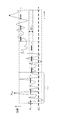
- FIG. 1 is a diagram showing an internal configuration of a satellite transmitter according to the first embodiment of the present invention.
- the satellite transmitter according to the first embodiment shown in FIG. 1 is intended to simultaneously transmit the transmission beams 16a to 16d as communication signals to one or more points m.
- Transmit beam 16a Transmit beam to Point 1
- Transmit beam 16b Transmit beam to Point 2
- Transmit beam 16c Transmit beam to Point m
- Transmit beam 16d Transmit beam to Point M
- the satellite transmitter 1 includes a DBF transmitter 2, multiplexers 12a to 12d, digital-analog converters (hereinafter referred to as DACs) 13a to 13d, amplifiers 14a to 14d, transmitting antenna elements 15a to 15d, PAPR calculator. 18 and an inter-beam relative phase calculation unit 19. Further, the DBF transmission unit 2 includes excitation coefficient multiplication units 11a to 11d, a storage device 17, and an excitation coefficient calculation unit 20.
- DACs digital-analog converters
- Each of the excitation coefficient multiplication units 11a to 11d in the DBF transmission unit 2 multiplies the received relay signal 51 by the excitation coefficient in the frequency domain.
- the multiplexing units 12a to 12d multiplex the relay signal, which is frequency-divided after being multiplied by the excitation coefficient, into a signal in the time domain.
- the DACs 13a to 13d convert the relay signal after being multiplexed by the multiplexing units 12a to 12d from a digital signal to an analog signal.
- the amplifiers 14a to 14d amplify the relay signals that have been converted into analog signals by the DACs 13a to 13d.
- the transmission antenna elements 15a to 15d are configured with the number of elements K. Here, K is an integer of 1 or more. Then, the transmitting antenna elements 15a to 15d radiate the relay signals amplified by the amplifiers 14a to 14d into space as radio waves.
- the PAPR calculator 18 calculates PAPR, which is the peak-to-average power ratio of each relay signal multiplexed by the multiplexers 12a to 12d.
- the inter-beam relative phase calculation unit 19 determines the relative phase between the beams based on the information regarding the PAPR calculated by the PAPR calculation unit 18.
- the storage device 17 in the DBF transmission unit 2 is a memory that stores the excitation coefficient used for beam forming. Further, the excitation coefficient calculation unit 20 in the DBF transmission unit 2 updates the beam forming excitation coefficient stored in the storage device 17 and the inter-beam phase information determined by the inter-beam relative phase calculation unit, after the update. Calculate the excitation coefficient of. Then, each of the excitation coefficient multiplication units 11a to 11d uses the excitation coefficient updated by the excitation coefficient calculation unit 20 to perform the multiplication process on the relay signal 51.
- the satellite transmitter 1 suppresses the PAPR of the signals input to the amplifiers 14a to 14d and reduces the backoff of the amplifiers 14a to 14d. It has a function of improving the outputs of the transmission beams 16a to 16d.
- FIG. 2 is a schematic diagram of the relay signal 51 input to the satellite transmitter 1 according to the first embodiment of the present invention.
- the relay signal 51 is a digital signal, and is a signal obtained by demultiplexing the signal in the total band ⁇ f with the resolution in the band ⁇ fch.
- the band ⁇ fch having the minimum resolution is called a sub-channel.
- Each subchannel has digital values of amplitude and phase.
- the number of sub-channels is N channels.
- N is an integer of 1 or more.
- relay signals transmitted as a total of M transmission beams 16a to 16d are band-divided and included in the total band ⁇ f as shown in FIG.
- FIG. 2 illustrates the case where the bands corresponding to the respective beams occupy the sub-channels in the order of the beam numbers.
- the bands corresponding to the beams do not have to be in the order shown in FIG.
- the total band of all beams may be equal to or less than the total band ⁇ f, and may not completely occupy the total band ⁇ f.
- FIG. 1 shows a case where there is one DBF transmission unit 2, and in this case, each of the M transmission beams 16a to 16d does not share the same sub-channel. That is, the frequencies are always different between the beams.
- relay signal 51 is described as a vector X, it becomes as shown in the following equation (1).
- Xn is the complex amplitude of subchannel n.
- the complex amplitude of the subchannel n belonging to the beam m is represented by Xn,m.
- a cluster corresponding to a set of complex amplitudes of sub-channels forming the beam m is represented by a vector xm.
- FIG. 3 is a diagram showing a first configuration example in which the relay signal 51 is input from the satellite receiver 31 to the satellite transmitter 1 according to the first embodiment of the present invention. Specifically, FIG. 3 shows a configuration in which the relay signal 51 generated by the satellite receiver 31 is input to the satellite transmitter 1 based on the relay signal 53 transmitted from the ground gateway station 52. ing.
- the ground gateway station 52 allocates the data to be transmitted to the M point by the satellite transmitter 1 to the M clusters in the total band ⁇ f as shown in the above equation (1) and transmits it to the satellite receiver 31 as real-time data. ..
- the satellite receiver 31 includes a receiving antenna 45, an ADC 43, and a demultiplexing unit 42.
- the ADC 43 generates a real-time digital signal by subjecting the relay signal 53 received via the receiving antenna 45 to analog-digital conversion (Analog Digital Convert: ADC).
- the demultiplexing unit 42 generates a relay signal 51 by demultiplexing the digitally converted real-time digital signal into a band ⁇ fch that is a subchannel in the frequency domain.
- the relay signal 51 generated by being demultiplexed can be expressed by the above equation (1).
- the terrestrial satellite control station 54 transmits, as a command signal 55, information on the beam forming excitation coefficient related to the transmission beam forming of the relay signal 51 to the satellite transmitter 1.
- the satellite transmitter 1 stores the command signal received by the command receiving antenna 56 in the storage device 17.
- the relay signal 51 and the beam forming excitation coefficient required for setting the transmission beam are controlled from the ground.
- the details of the beam forming excitation coefficient will be described later.
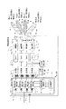
- FIG. 4 is a diagram showing a second configuration example in which the relay signal 51 is input from the satellite receiver 31 to the satellite transmitter 1 according to the first embodiment of the present invention. Specifically, in FIG. 4, the relay signal 51 generated by the satellite receiver 31 by receiving the beams transmitted from a plurality of ground stations as the reception beams 46A to 46D is input to the satellite transmitter 1. The structure is shown.
- the satellite repeater 200 shown in FIG. 4 includes a satellite receiver 31, a switch 48, a satellite transmitter 1, a command receiving antenna 56, and a satellite control unit 60.
- the satellite receiver 31 includes a DBF receiver 32, demultiplexers 42A to 42D, analog-digital converters (hereinafter referred to as ADCs) 43A to 43D, amplifiers 44A to 44D, receiving antenna elements 45A to 45D, and a vector combiner. It is configured with 47. Further, the DBF receiving unit 32 includes excitation coefficient multiplying units 41A to 41D and a storage device 49.
- ADCs analog-digital converters
- the satellite repeater 200 shown in FIG. 4 simultaneously receives reception beams 46A to 46D, which are communication signals from M'points of points 1'to M'.
- the satellite repeater 200 replaces each communication signal and synthesizes/separates bands.
- the satellite repeater 200 then forms M transmission beams 16a to 16d, which are new beams, and transmits the formed M transmission beams 16a to 16d to receivers at new points 1 to M on the ground.
- the purpose is to do.
- the satellite repeater 200 forms a reception beam by each individual DBF.
- the center frequency of the beam transmitted from the point m′ is fm′ and the band is ⁇ fm′.
- Point 1'to point M'where the terrestrial transmitter is located is any point on the ground covered by the radiation pattern of M'receive beams 46A to 46D.
- the satellite receiver 31 has K′ number of receiving antenna elements 45A to 45D, and the receiving antenna elements 45A to 45D form a receiving beam.
- the total band of the formed reception beam is within the total band ⁇ f of the transmission beam.
- the amplifiers 44A to 44D amplify the respective signals received by the receiving antenna elements 45A to 45D.
- the ADCs 43A to 43D convert the respective analog signals amplified by the amplifiers 44A to 44D into real-time digital signals.
- the demultiplexing units 42A to 42D demultiplex the digitally converted real-time digital signal into subchannels of the band ⁇ fch in the frequency domain.
- the excitation coefficient multiplication units 41A to 41D in the DBF reception unit 32 multiply the signals demultiplexed by the demultiplexers 42A to 42D by the excitation coefficient for reception beam formation stored in the storage device 49.
- the vector synthesizer 47 vector-synthesizes the signals multiplied by the excitation coefficient multiplication units 41A to 41D for each sub-channel. As a result, the signal in the receiving beam direction is restored.
- FIG. 5 is a conceptual diagram for explaining the function of the switch 48 according to the first embodiment of the present invention.
- the switch 48 has a function of exchanging signals demultiplexed for each sub-channel between sub-channels.
- the relay signal 51 is formed by the sub-channel switching function of the switch 48, and the formed relay signal 51 is output to the satellite transmitter 1.
- the switch 48 can change the band between the receive beam and the transmit beam with the sub-channel as the minimum variable band. Further, the switch 48 can also perform band division and combination.
- the excitation coefficient multiplied by the excitation coefficient multiplication units 11a to 11d is a complex amplitude for each sub-channel.
- the excitation coefficient is expressed by the following equation (2).
- Akn and ⁇ kn respectively indicate the following contents.
- ⁇ kn phase of excitation coefficient for sub-channel n of element k
- the complex amplitude after the excitation coefficient multiplication with respect to the element k is expressed by the following expression (3).
- the excitation coefficient calculation unit 20 outputs the excitation coefficient to the excitation coefficient multiplication units 11a to 11d.
- the excitation coefficient calculation unit 20 calculates the phase of the excitation coefficient as shown in the following expression (4).
- ⁇ k n,m is a phase for beam forming and represents an excitation coefficient phase of the element k forming the beam m of the sub-channel n.
- ⁇ k n,m is provided from the storage device 17 to the excitation coefficient calculation unit 20 as beam forming information.
- the excitation coefficient for beam forming together with the amplitude A k 0,m of the excitation coefficient is expressed by the following equation (5).
- a cluster that is a set of excitation coefficients of sub-channels forming the beam m is represented by a vector A k m .
- the method of setting the excitation coefficient for beam forming from the ground satellite control station 54 can be considered. Specifically, as shown in FIGS. 3 and 4, by transmitting a command from the ground satellite control station 54 to the satellite repeater 200, the storage device 49 in the satellite receiver 31 and the satellite transmitter 1 are transmitted. An excitation coefficient for beam forming can be set for each of the storage devices 17 of FIG.
- the command transmitted from the terrestrial satellite control station 54 is received by the command receiving antenna 56 provided in the satellite repeater 200, the command is transmitted to each of the storage device 49 and the storage device 17 for beam forming. Is stored as the excitation coefficient of.
- the transmission excitation coefficient and the reception excitation coefficient are appropriately distributed through the satellite control unit 60 and set in the satellite transmitter 1 and the satellite receiver 31. You may provide various functions.
- ⁇ m in the above equation (4) is an inter-beam relative phase, which is given from the inter-beam relative phase calculation unit 19 to the excitation coefficient calculation unit 20.
- the inter-beam relative phase ⁇ m is the relative phase between the beam 1 and the beam m. Therefore, the inter-beam relative phase ⁇ m has the same value between sub-channels of the same beam, and also takes the same value between elements of the same sub-channel.
- excitation coefficient A k of the element k output from the excitation coefficient calculation unit 20 to the excitation coefficient multiplication units 11a to 11d can be expressed by the following equation (6).
- the inter-beam relative phase ⁇ m is added as an extra phase in the equation (6).
- the beam formed is the same in the above equation (5) and the above equation (6).
- the relay signals output from the excitation coefficient multiplication units 11a to 11d are input to the multiplexing units 12a to 12d.
- the multiplexing units 12a to 12d have a function of multiplexing the output signals of the excitation coefficient multiplication units 11a to 11d on the frequency axis and converting them into real-time digital signals. That is, the multiplexing units 12a to 12d convert the spectrum data with the resolution of the band ⁇ fch into a real-time digital signal by performing a fast inverse Fourier transform.
- the real-time digital signals output from the multiplexing units 12a to 12d are input to the DACs 13a to 13d.
- the DACs 13a to 13d perform DA conversion of real-time digital signals. As a result, the outputs of the DACs 13a to 13d are converted into real-time analog signals.
- the outputs of the DACs 13a to 13d are input to the amplifiers 14a to 14d.
- the amplifiers 14a to 14d have a function of amplifying real-time analog signals output from the DACs 13a to 13d.
- TWTA Traveling Wave Tube Amplifier
- the amplifiers 14a to 14d have a non-linear characteristic region, and a back-off is provided to the amplifiers 14a to 14d in order to avoid the non-linear distortion occurring in this region. If PAPR can be suppressed, the amount of such back-off can be reduced, leading to an improvement in the power output from the amplifier.
- the outputs of the amplifiers 14a to 14d are emitted into the space by the transmitting antenna elements 15a to 15d configured as K elements #1 to #K, and the transmission beams 16a to 16d are spatially formed.
- the satellite transmitter 1 apart from the function of transmitting the relay signal 51 to the ground, part of the power of the real-time data output from the multiplexing units 12a to 12d is extracted and extracted.
- the input power is input to the PAPR calculator 18.
- the PAPR calculator 18 calculates the average power and peak power of the real-time digital signal of each element for each specific time. As a result, the PAPR calculator 18 calculates and compares the PAPR of each element.
- the inter-beam relative phase calculation unit 19 calculates the inter-beam relative phase ⁇ m of the above equation (4) based on the information on the PAPR of each element calculated by the PAPR calculation unit 18.
- the inter-beam relative phase ⁇ m calculated by the inter-beam relative phase calculation unit 19 is output to the excitation coefficient calculation unit 20.
- the inter-beam relative phase calculation unit 19 instructs the PAPR calculation unit 18 to update the PAPR measurement, if necessary.
- FIG. 6 is a flowchart showing a series of processes executed by the PAPR calculation unit 18 and the inter-beam relative phase calculation unit 19 in the first embodiment of the present invention.
- step S101 a part of the output data of the multiplexing units 12a to 12d is input to the PAPR calculation unit 18, and a series of operations is started.
- FIG. 7 is a diagram showing an outline of the real-time signal input to the PAPR calculation unit 18 in the first embodiment of the present invention.
- the PAPR calculation unit 18 will perform the processing from step S102 onward based on the waveform of FIG.
- step S102 the PAPR calculation unit 18 measures the average power p ave of all the elements while averaging the real-time signal at time t mea .
- step S103 the PAPR calculation unit 18 selects the element having the largest average power P ave as k max .
- step S104 the PAPR calculation unit 18 measures the average power p ave within the time t mea for the selected element k max . Subsequently, in step S105, the PAPR calculation unit 18 compares the average power p ave of the element k max with the specific power threshold p tot thre .
- the threshold value p tot thre for example, an amplifier backoff of about 10 dB is assumed. That is, if the average power p ave is sufficiently low from the non-linear region of the amplifier, it is not necessary to suppress PAPR. Therefore, when the average power p ave is less than or equal to the threshold value p tot thre , it is not necessary to perform the loop for calculating the phase for PAPR suppression after step S106, and the process returns to step S102.
- step S106 the PAPR calculation unit 18 measures the peak power P peak within the time t mea for the selected element k max .
- step S107 the PAPR calculation unit 18 calculates the PAPR of the element k max as PAPR(q) based on the average power p ave measured in step S104 and the peak power P peak measured in step S106. To do.
- This step S120 is composed of steps S108 to S110.
- step S120 it is assumed that the inter-beam relative phase ⁇ m is selected and read out from those stored as some series data in advance.
- the inter-beam relative phase calculation unit 19 stores in advance the inter-beam relative phase ⁇ 1 to the inter-beam relative phase ⁇ m as a plurality of series data.
- step S109 the inter-beam relative phase calculation unit 19 selects one inter-beam relative phase ⁇ 1 to inter-beam relative phase ⁇ M from the series data based on PAPR(q) calculated by the PAPR calculation unit 18. Perform the selection process to select. Further, in step S110, the inter-beam relative phase calculation unit 19 outputs the selected inter-beam relative phase ⁇ 1 to inter-beam relative phase ⁇ M to the excitation coefficient calculation unit 20.
- step S120 the satellite receiver 1 according to the first embodiment prepares relative phases between beams as a plurality of series data, and confirms by changing each excitation coefficient in units of series data. Update processing is being performed. As a result, if it is inappropriate, another series data is selected and each excitation coefficient is updated, so that a more appropriate excitation coefficient is sequentially calculated.
- the excitation coefficient calculation unit 20 When the excitation coefficient calculation unit 20 receives the inter-beam relative phase ⁇ 1 to the inter-beam relative phase ⁇ M selected by the inter-beam relative phase calculation unit 19 in step S120, it updates the new excitation coefficient based on the reception result. It is calculated as the subsequent excitation coefficient. Then, the excitation coefficient calculator 20 outputs the newly calculated and updated excitation coefficient to the excitation coefficient multipliers 11a to 11d.
- the relay signal output from the excitation coefficient multiplication units 11a to 11d and the real-time digital signal obtained by the multiplexing units 12a to 12d are also updated. To be done. Therefore, in step S111, the PAPR calculation unit 18 newly measures the average power p ave and the peak power P peak .
- step S112 the PAPR calculation unit 18 recalculates the PAPR of the element k max as PAPR(q′) based on the measurement result of step S111. Further, in step S113, the PAPR calculation unit 18 compares PAPR(q) and PAPR(q').
- PAPR(q) corresponds to the pre-update PAPR
- PAPR(q') corresponds to the post-update PAPR.
- PAPR(q) which is the PAPR before setting the inter-beam relative phase ⁇ m
- PAPR(q′) which is the PAPR after setting the inter-beam relative phase ⁇ m
- step S114 the PAPR calculation unit 18 updates the value of q to q'. That is, PAPR(q) is updated to PAPR(q') corresponding to the updated PAPR.
- step S115 the PAPR calculation unit 18 measures the average power P′ ave within the time t mea again.
- step S116 the PAPR calculation unit 18 determines the absolute value of the difference between the average power P ave of the element k max measured in step S104 and the average power P′ ave of the element k max measured in step S115. It is determined whether or not the threshold P thre is exceeded.
- the threshold value P thre is a value preset as a threshold value of a certain specific power difference.
- the process returns to step S111, and the optimization of the relative phase between beams is continued.
- the absolute value of this difference exceeds the threshold value, it can be considered that at least one of the channel setting, the beam setting, and the traffic amount of the relay signal 51 input to the satellite transmitter 1 has changed. it can.
- the power transmitted from each element also changes, so that k max is selected again. That is, in this case, the process returns to step S102, and the element having the maximum average power is selected again.
- the time t mea shown in FIGS. 6 and 7 is sufficiently long with respect to the band of the relay signal 51.
- the threshold P thre shown in step S116 of FIG. 6 needs to be appropriately selected according to the modulation scheme and band of the relay signal 51.
- the time t mea and the threshold value P thre may be changed by sending them as a command from the ground as the setting information, or may be determined in advance inside the satellite repeater 200.
- the satellite transmitter 1 has a feedback configuration that updates the excitation coefficient based on the outputs of the multiplexing units 12a to 12d so that the PAPR of the input to the amplifiers 14a to 14d is reduced. Is characterized by. As a result, it is possible to reduce the back-off margin, improve the power of the transmitter, and expect an increase in communication traffic.
- the satellite transmitter according to the first embodiment and the relay satellite communication system including the satellite transmitter have the following effects when compared with the related art.
- (Effect 1) The dynamic range can be secured by suppressing the PAPR even when a satellite-mounted DAC having a small number of resolution bits is used.
- (Effect 2) By reducing the backoff margin of the amplifier by suppressing the PAPR, it is possible to suppress the peak power and increase the transmission power.
- Each beam is a communication signal that is frequency-separated and has different information. Therefore, the relative phases between the beams do not affect each other in demodulation, and it is not necessary for the terrestrial receiving station to share the phase provided between the clusters in the satellite repeater.
- (Effect 4) Real-time traffic fluctuations can be tracked by the relative phase control between beams by the feedback configuration.
- FIG. 8 is a diagram showing an internal configuration of the satellite transmitter according to the second embodiment of the present invention.
- the basic configuration is the same as that shown in FIG. 1 in the first embodiment. 8 is different from the configuration of FIG. 1 in the first embodiment in the following points. That is, in the first embodiment, the frequency of each transmission beam is exclusive, and one DBF transmission unit 2 is configured for the satellite transmitter.
- each transmission beam is spatially exclusive and a plurality of M DBF transmission units 2a and 2b are provided.
- the number M is set according to the number M of beams to be transmitted. That is, in the second embodiment, M DBF transmitters 2 are provided corresponding to the number M of beams to be transmitted. This difference will be mainly described below.
- Each of the transmission beams 16a to 16d has the following meanings as in the first embodiment.
- Transmit beam 16a Transmit beam to Point 1
- Transmit beam 16b Transmit beam to Point 2
- Transmit beam 16c Transmit beam to Point m
- Transmit beam 16d Transmit beam to Point M
- the receiving point on the ground and the transmitting beam were arbitrary.
- the receiving point on the ground and the transmitting beam are assumed to be exclusive. That is, in the second embodiment, it is assumed that the receiving point on the ground is selected so that sufficient isolation can be ensured for forming the transmission beam.
- the isolation amount to be secured is required from the allowable value of C/I (Carrier-to-interference ratio) in the communication circuit design.
- Each of the DBF transmitters 2a and 2b includes excitation coefficient multiplication units 11a to 11d, an excitation coefficient calculation unit 20, and a storage device 17.
- the relay signal 51 is also individually input to each of the DBF transmitters 2a and 2b for each transmission beam. That is, the relay signal 51a is input to the DBF transmission unit 2a, and the relay signal 51b is input to the DBF transmission unit 2b.
- other beams other than the relay signals 51a and 51b have the same configuration.
- the processing after the multiplexing units 12a to 12d and the processing by the feedback configuration using the PAPR calculation unit 18 and the inter-beam relative phase calculation unit 19 are all the same as the configuration of FIG.
- -The number of points from which the satellite transmitter 1 simultaneously transmits communication signals is set to 1 to M.
- -The number of elements 15a to 15d of the transmitting antenna is set to K from 1 to K.
- the center frequency of the beam transmitted to the point m is fm, and the band is ⁇ fm.
- -Points 1 to M that receive the communication signal output from the satellite transmitter 1 are points on the ground that are covered by the radiation pattern of the M transmission beams 16a to 16d.
- the points 1 to M, which are receiving points on the ground, and the transmission beams 16a to 16d are arbitrary in the first embodiment, but are assumed to be exclusive in the second embodiment.
- FIG. 9 is a schematic diagram of relay signals 51a and 51b input to the satellite transmitter 1 according to the second embodiment of the present invention.
- Each of the relay signals 51a and 51b is a digital signal, and is a signal obtained by demultiplexing the signal in the total band ⁇ f with the resolution in the band ⁇ fch.
- the band ⁇ fch having the minimum resolution is called a sub-channel.
- Each subchannel has digital values of amplitude and phase.
- the number of sub-channels is N channels.
- one relay signal 51 includes all the transmission beams 16a to 16d.
- the transmission beams 16a to 16d are input to different DBF transmission units 2a and 2b as relay signals 51a and 51b different for each beam.
- the DBF transmitter 2a receives the transmission beam included in the relay signal 51a
- the DBF transmitter 2b receives the transmission beam included in the relay signal 51b.
- the transmission beams included in one relay signal 51 do not share the same sub-channel.
- the frequencies may be shared between the beams. That is, as shown in FIG. 9, the relay signal 51a and the relay signal 51b may use the same frequency.
- Each of the relay signal 51a input to the DBF transmission unit 2a and the relay signal 51b input to the DBF transmission unit 2b is multiplied by the excitation coefficient corresponding to the beam. That is, in the DBF transmitter 2a, the excitation coefficient corresponding to the beam 1 is read from the storage device 17. The read excitation coefficient is subjected to multiplication processing by the excitation coefficient multiplication units 11a to 11d after being given an inter-beam relative phase by the excitation coefficient calculation unit 20.
- the excitation coefficient corresponding to the beam 2 is read from the storage device 17.
- the read excitation coefficient is subjected to multiplication processing by the excitation coefficient multiplication units 11a to 11d after being given an inter-beam relative phase by the excitation coefficient calculation unit 20. The same process is performed in the remaining M ⁇ 2 DBF transmission units.
- the relay signals output from the M DBF transmitters 2 are input to the multiplexers 12a to 12d provided corresponding to the respective transmit antenna elements 15a to 15d.
- the number of inputs to each of the multiplexing units 2a to 2d is one.
- M relay signals corresponding to the number of beams are input to each of the multiplexing units 2a to 2d.
- the multiplexing units 12a to 12d have a function of adding the relay signals of all the beams for all the sub-channels, and after the addition, all the sub-channels on the frequency axis are combined and converted into a real-time digital signal. .. That is, the multiplexing units 12a to 12d convert the spectrum data with the resolution of the band ⁇ fch into a real-time digital signal by the IFFT.
- the operations of the DACs 13a to 13d, the amplifiers 14a to 14d, the transmitting antenna elements 15a to 15d, and the PAPR calculating unit 18, which are the multiplexing units 12a to 12d and later, are the same as those in the first embodiment. Further, regarding the inter-beam relative phase calculation unit 19, in the first embodiment, the calculated inter-beam relative phase is given to the single DBF transmission unit 2. On the other hand, the inter-beam relative phase calculation unit 19 according to the second embodiment provides the same inter-beam relative phase to the excitation coefficient calculation unit 20 in each DBF transmission unit 2a, 2b.
- the relay signal 51 is input from the satellite receiver 31.
- DBF receivers 32 are provided for the number of receive beams in the configuration of the satellite receiver 31 shown in FIG.
- the reception beam can be spatially exclusive like the transmission beam.
- the satellite transmitter according to the second embodiment and the relay satellite communication system including the satellite transmitter have the following effects when compared with the related art.
- (Effect 1) The dynamic range can be secured by suppressing the PAPR even when a satellite-mounted DAC having a small number of resolution bits is used.
- (Effect 2) By reducing the backoff margin of the amplifier by suppressing the PAPR, it is possible to suppress the peak power and increase the transmission power.
- (Effect 3) Each beam is spatially separated. Therefore, the relative phases between the beams do not affect each other in demodulation, and it is not necessary for the terrestrial receiving station to share the phase provided between the clusters in the satellite repeater.
- (Effect 4) The relay signal may use the same frequency between the beams, and the frequency utilization efficiency is improved.
- (Effect 5) Real-time traffic fluctuations can be tracked by the relative phase control between beams by the feedback configuration.
- Embodiment 3 ⁇ Structure>
- the PAPR calculation process and the feedback control process for updating the excitation coefficient based on the PAPR calculation result are performed inside the satellite transmitter 1 of the satellite repeater 200.
- the third embodiment a case will be described in which the PAPR calculation process and the feedback control process for updating the excitation coefficient are performed on the ground side.
- the element having the maximum PAPR is Calculation can be performed on the ground side. Therefore, in this case, a PAPR calculation unit and an inter-beam relative phase calculation unit are provided on the ground side, and the inter-beam relative phase ⁇ m is given from the ground to the satellite repeater 200 by a command. be able to.
- FIG. 10 is a diagram showing a configuration example of a relay satellite communication system including a satellite relay 200 according to the third embodiment of the present invention.
- the satellite transmitter 1 included in the satellite repeater 200 according to the third embodiment shown in FIG. 10 has a transmission beam as a communication signal for one or more points m, as in the first embodiment.
- the purpose is to simultaneously transmit 16a to 16d.
- Each of the transmission beams 16a to 16d also means the following, as in the first embodiment.
- Transmit beam 16a Transmit beam to Point 1
- Transmit beam 16b Transmit beam to Point 2
- Transmit beam 16c Transmit beam to Point m
- Transmit beam 16d Transmit beam to Point M
- points 1 to M which receive the communication signal output from the satellite transmitter 1, are set as arbitrary points on the ground that are covered by the radiation pattern of the M transmission beams 16a to 16d.
- the transmission beams 16a to 16d are assumed to have no frequency overlap. That is, it is assumed that the frequencies of the transmission beams 16a to 16d in the third embodiment are mutually exclusive, as in the first embodiment.
- the PAPR calculation unit 18 and the inter-beam relative phase calculation unit 19 for suppressing the PAPR are provided in the satellite transmitter 1.
- the PAPR calculator 18 and the inter-beam relative phase calculator 19 are not provided in the satellite transmitter 1. Instead, the ground communication control station 57 calculates the phase for reducing the PAPR, and the set value of the excitation coefficient to be updated is sent as a command to the satellite repeater 200 through the ground satellite control station 54.
- the operation of the satellite repeater 200 is the same as that of the first embodiment except that the PAPR calculating unit 18 and the inter-beam relative phase calculating unit 19 are not present, and therefore the description thereof is omitted.
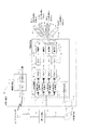
- FIG. 11 is a schematic diagram of the communication control station 57 according to the third embodiment of the present invention.
- the communication control station 57 shown in FIG. 11 includes a relay signal generation unit 72, an element selection unit 73, a multiplexing unit 74, a PAPR calculation unit 75, an inter-beam relative phase calculation unit 76, an excitation coefficient calculation unit 77, and a transmission beam control. It is configured to include a portion 78.
- a signal for relaying from the ground communication network 71 to another ground station via the satellite relay 200 is input to the communication control station 57 from the ground communication network 71.
- the relay signal generation unit 72 in the communication control station 57 generates a relay signal as shown in FIG. 2 as the relay signal 58 based on this signal input from the ground communication network 71.
- the relay signal 58 is transmitted to the satellite relay 200 as the relay signal 53 through the ground gateway station 52.
- the element selection unit 73 inputs a part of the relay signal 58 generated by the relay signal generation unit 72.
- the element selection unit 73 multiplies the beam forming excitation coefficient provided from the transmission beam control unit 78 by the relay signal 58 to obtain a signal similar to the element signal generated by the DBF transmission unit 2 on the satellite repeater 200. Is simulated.
- the element selection unit 73 selects the element with the highest power from the simulated element signals, and outputs the relay signal after the excitation coefficient multiplication of the selected element to the multiplexing unit 74.
- the multiplexing unit 74 has a function of multiplexing the relay signal of the element having the largest average power on the frequency axis and converting it into a real-time digital signal. That is, the multiplexing unit 74 converts the spectrum data having the resolution of the band ⁇ fch into a real-time digital signal by performing a fast inverse Fourier transform.
- the real-time digital signal output from the multiplexer 74 is input to the PAPR calculator 75.
- the PAPR calculation unit 75 calculates the PAPR by measuring the average power and the peak power at each specific time.
- the PAPR information calculated by the PAPR calculation unit 75 is input to the inter-beam relative phase calculation unit 76.
- the inter-beam relative phase calculation unit 76 selects one inter-beam relative phase ⁇ m based on the PAPR information.
- the processing by the inter-beam relative phase calculation unit 76 is the same as the processing in step 120 of FIG.
- Information on the inter-beam relative phase ⁇ m is sent from the inter-beam relative phase calculation unit 76 to the excitation coefficient calculation unit 77 and the transmission beam control unit 78.
- the transmission beam control unit 78 adds the inter-beam relative phase ⁇ m sent from the inter-beam relative phase calculation unit 76 and the excitation coefficient phase for beam forming, and then generates a new excitation coefficient.
- the transmission beam controller 78 gives the generated new excitation coefficient to the element selector 73. As a result, a similar series of processes is repeated using the updated excitation coefficient.
- the excitation coefficient calculator 77 calculates the excitation coefficient A k after adding the phase of the beam forming excitation coefficient and the inter-beam relative phase ⁇ m, and transmits it to the ground satellite control station 54 as the excitation coefficient 59.
- the excitation coefficient 59 sent as the command signal 55 from the terrestrial satellite control station 54 is set in the excitation coefficient multiplication units 11a to 11d in the DBF transmission unit 2 through the storage device 17.
- the communication control station 57 side calculates in advance the relative phase between beams that reduces the PAPR of the transmission antenna elements 15a to 15d of the satellite transmitter 1, and also combines the excitation coefficient A k with the excitation coefficient for beam forming.
- the configuration inside the satellite repeater 200 can be simplified.
- the relay satellite communication system has the following effects when compared with the related art.
- (Effect 1) The dynamic range can be secured by suppressing the PAPR even when a satellite-mounted DAC having a small number of resolution bits is used.
- (Effect 2) By reducing the backoff margin of the amplifier by suppressing the PAPR, it is possible to suppress the peak power and increase the transmission power.
- (Effect 3) The configuration of the satellite repeater can be simplified by calculating the PAPR reduction phase on the ground station side.
- Effect 4 Real-time traffic fluctuations can be tracked by the relative phase control between beams by the feedback configuration.
- the inter-beam relative phase ⁇ m is a parameter given for each transmission beam.
- the inter-beam relative phase ⁇ m is a parameter that can control the inter-beam relative phase without affecting the transmission beam formation itself.
- the satellite transmitter and the relay satellite communication system calculate the inter-beam relative phase that suppresses the peak power of the transmitting antenna element based on the PAPR calculation result, and use the calculated inter-beam relative phase for excitation. It has a configuration for updating the coefficient. As a result, it is possible to realize the satellite transmitter and the relay satellite communication system in which the limitation of the transmission power is suppressed and it is not necessary to share the phase control information between the transmitter side and the receiver side.
- excitation coefficient update processing is performed by either the satellite transmitter side as described in the first and second embodiments or the ground side as described in the third embodiment. It is feasible.
Landscapes
- Engineering & Computer Science (AREA)
- Computer Networks & Wireless Communication (AREA)
- Signal Processing (AREA)
- Physics & Mathematics (AREA)
- Astronomy & Astrophysics (AREA)
- Aviation & Aerospace Engineering (AREA)
- General Physics & Mathematics (AREA)
- Radio Relay Systems (AREA)
Abstract
衛星送信機は、K個の送信アンテナ素子と、K個のデジタル信号のそれぞれについて周波数軸上で合波した後、時間領域のデジタル信号に変換する合波部と、デジタル-アナログ変換器と、K個のデジタル信号のそれぞれに関するPAPRを算出するPAPR算出部と、K個のPAPRに基づき、送信アンテナ素子のピーク電力を抑圧するビーム間相対位相を算出するビーム間相対位相算出部と、ビーム間相対位相とビーム形成用励振係数とに基づいて、K個の更新後の励振係数を演算する励振係数演算部と、受信した中継信号に対して周波数領域でK個の更新後の励振係数をそれぞれ乗算することで、合波部に出力するための周波数領域のデジタル信号を生成する励振係数乗算部とを備える。
Description
この発明は、送信アンテナ素子のピーク電力の抑圧を図る衛星送信機および中継衛星通信システムに関する。
通信容量の増大に伴い、通信トラフィックの制御を柔軟に行う衛星通信システムが要求されている。通信トラフィックの最適化としては、エリアフレキシビリティの制御として、複数のアンテナの励振係数、すなわち、振幅および位相、を制御することで、送信ビームおよび受信ビームを形成するビームフォーミングネットワーク(BFN)がある。
ビームフォーミングの方式としては、マイクロ波の移相器を用いるマイクロ波ビームフォーミング(MBF)、およびデジタル信号処理により励振係数の制御を行うデジタルビームフォーミング(DBF)がある。デジタルビームフォーミングは、マイクロ波ビームフォーミングに比べてビームを集積可能なことから、ビーム数の増大が望める。
例えば、デジタルビームフォーミングの方式として、受信ビームを周波数分割した後、ディジタルビーム形成器にて各ビームに対して重み付け係数を用いた積和演算を行い、ビーム形成する中継装置に関する技術がある(例えば、特許文献1参照)。
特許文献1に係る中継装置の構成では、入力信号のない周波数においてDBF演算を行わないことで、デジタル処理における電力消費が下げられている。さらに、特許文献1に係る中継装置で用いられているデジタルビームフォーミングの方式は、送信ビームにもそのまま適用でき、送信機においても、同様の効果が望める。
特許文献1に係る従来の中継装置は、上述した構成をとることにより、変調方式を問わずに、ビームに対応した励振係数を各ビームの帯域ごとに各素子に設定することで、ビーム形成する機能を有する。また、特許文献1に係る従来の中継装置は、ビームの占有帯域が変化した場合にも、柔軟にビーム形成が可能である。
また、マルチキャリア信号の送受方法に関して、多数のサブキャリアを同時に送信する場合には、それらのサブキャリアの位相関係により、送信信号の振幅が大きく変動することが知られている。
通常、送信機には、送信電力を増幅させる増幅器が設けられている。しかしながら、振幅の変動が大きい場合には、増幅器における非線形領域を用いることによる非線形歪みを避けるために、バックオフマージンを大きくとる必要がある。これにより、増幅器の使用可能なダイナミックレンジが抑圧されてしまう。
このような問題が発生する、振幅が大きく変動する変調方法としては、直交周波数分割多重方式(OFDM:orthogonal frequency-division multiplexing)が挙げられる。本変調方式では、送信機に対して、ピーク対平均電力比(PAPR:Peak to Average Power Ratio)を下げる方法が、従来技術として考えられている。
OFDM送信器におけるPAPR抑圧方法としては、クリッピング法、フィルタリング法、PTS(Partial Trasmit Sequence)法などがある。ここで、PTS法は、送信信号のひずみを生じさせずにピーク抑圧できるという点で、有利な方式とされている(例えば、非特許文献1参照)。
PTS法は、マルチキャリアを周波数領域でいくつかのクラスタに分割した上で、分割したマルチキャリアをIFFT(Inverse :高速逆フーリエ変換)により周波数領域から時間領域に直している。さらに、PTS法では、時間領域でクラスタ間に適切な位相をつけた上で、クラスタを合波することにより、PAPRの抑圧ができる。PTS法では、このクラスタ間につけた位相を、受信機側と共有しておくことで、復調時にマルチキャリア全体を復元できる。
L.J.Cimini and N.R.Sollenberger,「Peak-to-Average power ratio reduction of an OFDM signal using partial transmit sequences」,IEEE Commun.Lett,vol.4,no.3,pp.86-88,March,2000
しかしながら、従来技術は、以下のような課題を有する。
特許文献1に係る従来の中継装置において、励振係数は、各素子および各ビームに対して独立に設定できる。各素子に乗算する励振係数が制御されることで、送信アンテナアレーから出射される合成波面の位相が制御され、ビームが形成される。
特許文献1に係る従来の中継装置において、励振係数は、各素子および各ビームに対して独立に設定できる。各素子に乗算する励振係数が制御されることで、送信アンテナアレーから出射される合成波面の位相が制御され、ビームが形成される。
すなわち、特許文献1に係る従来の中継装置では、変調方式を問わずにビームに対応した励振係数をビームの帯域ごとに各素子に設定することで、ビーム形成を行うことができる。しかしながら、特定の素子に着目したときには、特許文献1に係る従来の中継装置では、異なるビームを形成する全帯域の信号が同一の素子を通過することとなり、マルチキャリアの送信機と同様に、PAPRが増大する。よって、送信増幅器のバックオフマージンを大きくとる必要がある。このため、特許文献1に係る従来の中継装置は、送信電力が制限されてしまうという課題があった。
また、非特許文献1に記載されたようなPTS法では、マルチキャリアを単一の受信機で復調する際に、PAPRの抑圧のためにクラスタ間に付与した位相制御情報を、送信機側から受信機側へ、他の方法により共有する必要があるという課題があった。
本発明は、前記のような課題を解決するためになされたものであり、送信電力の制限が抑制され、かつ、送信機側と受信機側との間で位相制御情報を共有する必要がない衛星送信機および中継衛星通信システムを得ることを目的とする。
本発明に係る衛星送信機は、K個のアナログ信号のそれぞれに基づいて、地上の1以上の任意の地点に互いに周波数が異なる送信ビームを放射するK個の送信アンテナ素子と、周波数ごとに分波されている周波数領域のデジタル信号を送信アンテナ素子の素子数に対応したK個として入力し、K個のデジタル信号のそれぞれについて周波数軸上で合波した後、時間領域のデジタル信号に変換する合波部と、K個のデジタル信号のそれぞれをアナログ信号に変換するデジタル-アナログ変換器と、送信ビームを形成するためのK個の励振係数をビーム形成用励振係数として保存する記憶装置と、合波部で変換されたK個のデジタル信号のそれぞれに関するピーク対平均電力比をPAPRとして算出するPAPR算出部と、K個のPAPRに基づき、送信アンテナ素子のピーク電力を抑圧するビーム間相対位相を算出するビーム間相対位相算出部と、ビーム間相対位相とビーム形成用励振係数とに基づいて、K個の更新後の励振係数を演算する励振係数演算部と、受信した中継信号に対して周波数領域でK個の更新後の励振係数をそれぞれ乗算することで、合波部に出力するための周波数領域のデジタル信号を生成する励振係数乗算部とを備えるものである。
また、本発明に係る衛星送信機は、K個のアナログ信号のそれぞれに基づいて、地上の空間的に異なるM地点に送信ビームを放射するK個の送信アンテナ素子と、周波数ごとに分波されている周波数領域のデジタル信号を送信アンテナ素子の素子数に対応したK個として入力し、K個のデジタル信号のそれぞれについて周波数軸上で合波した後、時間領域のデジタル信号に変換する合波部と、K個のデジタル信号のそれぞれをアナログ信号に変換するデジタル-アナログ変換器と、送信ビームを形成するためのK個の励振係数をビーム形成用励振係数として保存する記憶装置と、合波部で変換されたK個のデジタル信号のそれぞれに関するピーク対平均電力比を、PAPRとして算出するPAPR算出部と、K個のPAPRに基づき、送信アンテナ素子のピーク電力を抑圧するビーム間相対位相を算出するビーム間相対位相算出部と、ビーム間相対位相とビーム形成用励振係数とに基づいて、K個の更新後の励振係数を演算する励振係数演算部と、受信した中継信号に対して周波数領域でK個の更新後の励振係数をそれぞれ乗算することで、合波部に出力するための周波数領域のデジタル信号を生成する励振係数乗算部とを備え、記憶装置、励振係数演算部、および励振係数乗算部を有して構成されるDBF送信部がM個設けられており、中継信号は、個別のM個の中継信号として構成され、M個のDBF送信部は、個別のM個の中継信号のそれぞれに基づいて、周波数領域のデジタル信号をM個出力し、合波部は、M個の周波数領域のデジタル信号を周波数ごとに合算することで合算後のK個のデジタル信号を生成し、合算後のK個のデジタル信号のそれぞれについて周波数軸上で合波した後、時間領域のデジタル信号に変換し、ビーム間相対位相算出部は、算出したビーム間相対位相をM個のDBF送信部のそれぞれに対して出力するものである。
また、本発明に係る中継衛星通信システムは、地上に設けられた地上ゲートウェイ局、通信制御局、および地上衛星管制局と、衛星受信機および衛星送信機を有する衛星中継器とを備えて構成された中継衛星通信システムであって、通信制御局は、中継信号を生成し、生成した中継信号に対して衛星送信機に設けられている送信アンテナ素子の各素子の時間領域のデジタル信号のそれぞれに関するピーク対平均電力比をPAPRとして算出し、PAPRに基づき、送信アンテナ素子のピーク電力を抑圧するビーム間相対位相を算出し、ビーム間相対位相に基づいて衛星送信機から放射される送信ビームのビーム形成用励振係数を決定し、ビーム間相対位相とビーム形成用励振係数とに基づいてビーム形成用励振係数を更新することで、更新後の励振係数を演算し、地上ゲートウェイ局は、通信制御局で生成された中継信号を衛星受信機の送信し、地上衛星管制局は、通信制御局で生成された更新後の励振係数を衛星送信機に送信し、衛星受信機は、地上ゲートウェイ局から受信した中継信号から、周波数ごとに分波された周波数領域のデジタル信号を生成し、衛星送信機は、K個のアナログ信号のそれぞれに基づいて、地上の1以上の任意の地点に互いに周波数が異なる送信ビームを放射するK個の送信アンテナ素子と、更新後の周波数領域のデジタル信号を送信アンテナ素子の素子数に対応したK個として入力し、K個のデジタル信号のそれぞれについて周波数軸上で合波した後、時間領域のデジタル信号に変換する合波部と、K個のデジタル信号のそれぞれをアナログ信号に変換するデジタル-アナログ変換器と、地上衛星管制局から更新後の励振係数を受信し、衛星受信機で生成された周波数領域のデジタル信号に対して周波数領域で更新後の励振係数を乗算することで、合波部に出力するための更新後の周波数領域のデジタル信号を生成する励振係数乗算部とを有するものである。
本発明によれば、PAPRの算出結果に基づいて送信アンテナ素子のピーク電力を抑圧するビーム間相対位相を算出し、算出したビーム間相対位相を用いて励振係数を更新する構成を備えている。この結果、送信電力の制限が抑制され、かつ、送信機側と受信機側との間で位相制御情報を共有する必要がない衛星送信機および中継衛星通信システムを得ることができる。
以下、この発明をより詳細に説明するために、この発明を実施するための形態について、添付の図面に従って説明する。
実施の形態1.
<構成>
図1は、本発明の実施の形態1に係る衛星送信機の内部構成を示した図である。図1に示した本実施の形態1に係る衛星送信機は、1以上の地点mに対して、通信信号としての送信ビーム16a~16dを同時に送信することを目的とする。ここで、mは、Mを1以上の整数としたときに、m=1~Mとして表わされる。
<構成>
図1は、本発明の実施の形態1に係る衛星送信機の内部構成を示した図である。図1に示した本実施の形態1に係る衛星送信機は、1以上の地点mに対して、通信信号としての送信ビーム16a~16dを同時に送信することを目的とする。ここで、mは、Mを1以上の整数としたときに、m=1~Mとして表わされる。
各送信ビーム16a~16dは、以下のことを意味している。
送信ビーム16a:地点1への送信ビーム
送信ビーム16b:地点2への送信ビーム
送信ビーム16c:地点mへの送信ビーム
送信ビーム16d:地点Mへの送信ビーム
送信ビーム16a:地点1への送信ビーム
送信ビーム16b:地点2への送信ビーム
送信ビーム16c:地点mへの送信ビーム
送信ビーム16d:地点Mへの送信ビーム
衛星送信機1は、DBF送信部2、合波部12a~12d、デジタル-アナログ変換器(以下、DACと記載する)13a~13d、増幅器14a~14d、送信アンテナ素子15a~15d、PAPR算出部18、およびビーム間相対位相算出部19を備えて構成されている。また、DBF送信部2は、励振係数乗算部11a~11d、記憶装置17、および励振係数演算部20を備えて構成されている。
DBF送信部2内の励振係数乗算部11a~11dのそれぞれは、受信した中継信号51に対して、周波数領域で励振係数を乗算する。合波部12a~12dは、励振係数が乗算された後、周波数ごとに分波されている中継信号を、時間領域の信号に合波する。
DAC13a~13dは、合波部12a~12dにより合波された後の中継信号を、デジタル信号からアナログ信号に変換する。増幅器14a~14dは、DAC13a~13dによりアナログ信号に変換された後の中継信号を増幅する。送信アンテナ素子15a~15dは、素子数Kとして構成されている。ここで、Kは、1以上の整数である。そして、送信アンテナ素子15a~15dは、増幅器14a~14dにより増幅された中継信号を、電波として空間に放射する。
PAPR算出部18は、合波部12a~12dにより合波されたそれぞれの中継信号のピーク対平均電力比であるPAPRを算出する。ビーム間相対位相算出部19は、PAPR算出部18により算出されたPAPRに関する情報を元に、ビーム間の相対位相を決定する。
DBF送信部2内の記憶装置17は、ビーム形成を行うために使用される励振係数を保存するメモリである。また、DBF送信部2内の励振係数演算部20は、ビーム間相対位相算出部によって決定されたビーム間の位相情報と、記憶装置17に記憶されているビーム形成用の励振係数から、更新後の励振係数を算出する。そして、励振係数乗算部11a~11dのそれぞれは、励振係数演算部20によって更新された励振係数を用いて、中継信号51に対して乗算処理を行うこととなる。
図1の構成を備えることで、本実施の形態1に係る衛星送信機1は、増幅器14a~14dに入力される信号のPAPRを抑圧し、増幅器14a~14dのバックオフを低減することで、送信ビーム16a~16dの出力を向上させる機能を有する。
<動作>
次に、本実施の形態1に係る衛星送信機1の具体的な動作について説明する。具体的な動作に関しては、以下の条件下で説明する。
・衛星送信機1から同時に通信信号を送信する地点を、1~MのM個とする。
・送信アンテナ素子15a~15dの数を、1~KのK個とする。
・衛星送信機1から通信信号として出力された送信ビーム16a~16dについて、地点mに対して送信するビームの中心周波数はfm、帯域はΔfmとする。
・衛星送信機1から出力された通信信号を受信する地点1~地点Mは、M個の送信ビーム16a~16dによる放射パターンでカバーされる、地上の任意の点とする。
次に、本実施の形態1に係る衛星送信機1の具体的な動作について説明する。具体的な動作に関しては、以下の条件下で説明する。
・衛星送信機1から同時に通信信号を送信する地点を、1~MのM個とする。
・送信アンテナ素子15a~15dの数を、1~KのK個とする。
・衛星送信機1から通信信号として出力された送信ビーム16a~16dについて、地点mに対して送信するビームの中心周波数はfm、帯域はΔfmとする。
・衛星送信機1から出力された通信信号を受信する地点1~地点Mは、M個の送信ビーム16a~16dによる放射パターンでカバーされる、地上の任意の点とする。
図2は、本発明の実施の形態1に係る衛星送信機1に入力される中継信号51の概要図である。中継信号51は、デジタル信号であり、総帯域Δfの信号が帯域Δfchの分解能で分波された信号である。ここで、最小の分解能である帯域Δfchをサブチャネルと呼ぶ。各サブチャネルは、振幅と位相のデジタル値をもつ。以下の説明では、サブチャネル数は、Nチャネルとする。ここで、Nは、1以上の整数である。
また、総計M個の送信ビーム16a~16dとして送信される中継信号が、図2に示すように、帯域分割されて総帯域Δfの中に含まれているものとする。図2においては、各ビームに対応した帯域が、ビーム番号順に、サブチャネルを占有している場合を例示している。しかしながら、各ビームに対応した帯域は、図2に示すような順でなくてもよい。また、全ビームの帯域の合計は、総帯域Δf以下であればよく、完全に総帯域Δfを占有していなくてもよい。
また、図1において、DBF送信部2は1つである場合を示しており、この場合においては、M個の送信ビーム16a~16dのそれぞれは、同一のサブチャネルを共有しないものとする。すなわち、ビーム間では周波数は必ず異なっているものとする。
中継信号51をベクトルXとして記述すると、下式(1)のようになる。

上式(1)に示したように、n=0~N-1とした場合に、Xnは、サブチャネルnの複素振幅である。ビームmに属するサブチャネルnの複素振幅をXn、mで表す。また、ビームmを構成するサブチャネルの複素振幅の組に相当するクラスタを、ベクトルxmで表す。
図3は、本発明の実施の形態1に係る衛星送信機1に対して、衛星受信機31から中継信号51が入力される第1の構成例を示した図である。具体的には、図3は、地上ゲートウェイ局52から送信された中継信号53に基づいて、衛星受信機31によって生成された中継信号51が、衛星送信機1に対して入力される構成を示している。
地上ゲートウェイ局52は、衛星送信機1によってM地点に送信したいデータを、上式(1)のように総帯域Δf内のM個のクラスタに割当て、実時間データとして衛星受信機31に送信する。
衛星受信機31は、受信アンテナ45、ADC43、および分波部42を備えて構成されている。ADC43は、受信アンテナ45を介して受信した中継信号53を、アナログ-デジタル変換(Analog Digital Convert:ADC)することにより、実時間のデジタル信号を生成する。
分波部42は、デジタル変換された実時間のデジタル信号を、周波数領域のサブチャネルである帯域Δfchに分波することで、中継信号51を生成する。分波されることで生成された中継信号51は、上式(1)のように表すことができる。
地上衛星管制局54は、中継信号51の送信ビーム形成に関連するビーム形成用励振係数の情報を、コマンド信号55として衛星送信機1に対して送信する。これに対して、衛星送信機1は、コマンド受信アンテナ56によって受信したコマンド信号を、記憶装置17に記憶させる。
このような構成により、送信ビームの設定に必要な中継信号51およびビーム形成用励振係数は、地上から制御される。なお、ビーム形成用励振係数の詳細については、後述する。
次に、図4は、本発明の実施の形態1に係る衛星送信機1に対して、衛星受信機31から中継信号51が入力される第2の構成例を示した図である。具体的には、図4は、複数の地上局から送信されたビームを受信ビーム46A~46Dとして受信することで衛星受信機31によって生成された中継信号51が、衛星送信機1に入力される構成を示している。
図4に示す衛星中継器200は、衛星受信機31、スイッチ48、衛星送信機1、コマンド受信アンテナ56、および衛星制御ユニット60を備えて構成されている。
衛星受信機31は、DBF受信部32、分波部42A~42D、アナログ-デジタルコンバータ(以下、ADCと記載する)43A~43D、増幅器44A~44D、受信アンテナ素子45A~45D、およびベクトル合成器47を備えて構成されている。また、DBF受信部32は、励振係数乗算部41A~41D、および記憶装置49を備えて構成されている。
図4に示す衛星中継器200は、地点1’~M’のM’個の地点からの通信信号である受信ビーム46A~46Dを同時に受信する。衛星中継器200は、各通信信号の入れ替え、帯域の合成・分離を行う。衛星中継器200は、その後、新たなビームであるM個の送信ビーム16a~16dを形成し、形成したM個の送信ビーム16a~16dを地上の新たな地点1~地点Mの受信者へ送信することを目的とする。
図4に基づく衛星受信機31の具体的な動作に関しては、以下の条件下で説明する。
・複数の地上局に対して、衛星中継器200がそれぞれ個別のDBFによる受信ビームを形成する。
・送信ビームと同様に、通信信号である受信ビーム46A~46Dについて、地点m’から送信されるビームの中心周波数はfm’、帯域はΔfm’とする。
・地上送信局がある地点1’~地点M’は、M’個の受信ビーム46A~46Dによる放射パターンでカバーされる、地上の任意の点とする。
・衛星受信機31は、素子数K’個の受信アンテナ素子45A~45Dを有しており、受信アンテナ素子45A~45Dにより受信ビームを形成する。
・形成される受信ビームの総帯域は、送信ビームの総帯域Δfに収まっているものとする。
・複数の地上局に対して、衛星中継器200がそれぞれ個別のDBFによる受信ビームを形成する。
・送信ビームと同様に、通信信号である受信ビーム46A~46Dについて、地点m’から送信されるビームの中心周波数はfm’、帯域はΔfm’とする。
・地上送信局がある地点1’~地点M’は、M’個の受信ビーム46A~46Dによる放射パターンでカバーされる、地上の任意の点とする。
・衛星受信機31は、素子数K’個の受信アンテナ素子45A~45Dを有しており、受信アンテナ素子45A~45Dにより受信ビームを形成する。
・形成される受信ビームの総帯域は、送信ビームの総帯域Δfに収まっているものとする。
増幅器44A~44Dは、受信アンテナ素子45A~45Dにより受信されたそれぞれの信号を増幅する。ADC43A~43Dは、増幅器44A~44Dにより増幅されたそれぞれのアナログ信号を、実時間のデジタル信号に変換する。
分波部42A~42Dは、デジタル変換された実時間のデジタル信号を、周波数領域における帯域Δfchのサブチャネルに分波する。DBF受信部32内の励振係数乗算部41A~41Dは、分波部42A~42Dによって分波された信号に対して、記憶装置49に記憶された受信ビーム形成用の励振係数を乗算する。
ベクトル合成器47は、励振係数乗算部41A~41Dにより乗算された信号を、それぞれのサブチャネルごとにベクトル合成する。これにより、受信ビーム方向の信号が復元される。
次に、衛星受信機31と衛星送信機1との間に設けられたスイッチ48の動作について説明する。図5は、本発明の実施の形態1に係るスイッチ48の機能を説明するための概念図である。スイッチ48は、サブチャネルごとに分波された信号をサブチャネル間で入れ替える機能を持つ。
従って、スイッチ48の働きにより、受信ビームと送信ビームとの間でサブチャネルの入替を行うことができる。スイッチ48によるサブチャネルの入替機能により、中継信号51が形成され、形成された中継信号51は、衛星送信機1に出力される。
図5においては、受信ビームと送信ビームは、帯域の変更がなく、1対1の対応となっている場合を例示している。しかしながら、スイッチ48は、受信ビームと送信ビームとの間で、サブチャネルを最小可変帯域として、帯域を変えることができる。さらに、スイッチ48は、帯域の分割と合成を行うこともできる。
次に、図4に戻り、衛星送信機1側の説明を行う。DBF送信部2内の励振係数乗算部11a~11dのそれぞれは、中継信号51を素子k=1~Kに分波した後の信号に対して、励振係数を乗算して、ビームを形成する。励振係数乗算部11a~11dで乗算する励振係数は、サブチャネルごとの複素振幅である。励振係数は、下式(2)のように表される。

上式(2)において、Aknおよびθknは、それぞれ以下の内容を示している。
Akn:素子kのサブチャネルnに対する励振係数の振幅
θkn:素子kのサブチャネルnに対する励振係数の位相
Akn:素子kのサブチャネルnに対する励振係数の振幅
θkn:素子kのサブチャネルnに対する励振係数の位相
励振係数乗算部11a~11dの出力として、素子kに対する励振係数乗算後の複素振幅は、下式(3)のようになる。

上式(3)中に示された記号○は、ベクトルのアダマール積を表す。この複素振幅ベクトルの素子kに対する和が、結果的に空間的なビーム形状を決定する。
励振係数演算部20は、励振係数乗算部11a~11dに励振係数を出力する。励振係数演算部20では、下式(4)に示すような励振係数の位相の演算が行われる。

上式(4)において、φk
n、mは、ビーム形成を行うための位相でサブチャネルnのビームmを形成する素子kの励振係数位相を表す。φk
n、mは、ビーム形成情報として記憶装置17から励振係数演算部20に与えられる。励振係数の振幅Ak
0、mと合わせて、ビーム形成用の励振係数は、下式(5)のように表される。

ここで、ビームmを構成するサブチャネルの励振係数の組であるクラスタを、ベクトルAk
mで表す。
このビーム形成用の励振係数は、地上衛星管制局54から設定する方法が考えられる。具体的には、図3および図4に示したように、地上衛星管制局54からコマンドを衛星中継器200に送信することで、衛星受信機31内の記憶装置49、および衛星送信機1内の記憶装置17のそれぞれに対して、ビーム形成用の励振係数を設定することができる。
図4の例では、地上衛星管制局54から送信されたコマンドは、衛星中継器200に設けられたコマンド受信アンテナ56により受信された後、記憶装置49および記憶装置17の各々に、ビーム形成用の励振係数として格納される。この時、図4に示したように、衛星制御ユニット60を介して、送信用の励振係数と受信用の励振係数を各々適切に振り分けて、衛星送信機1と衛星受信機31に設定するような機能を設けてもよい。
また、上式(4)におけるψmは、ビーム間相対位相であり、ビーム間相対位相算出部19から励振係数演算部20に与えられる。
ビーム間相対位相ψmは、ビーム1とビームmとの相対位相である。よって、ビーム間相対位相ψmは、同一ビームのサブチャネル間では同一値であり、また、同一サブチャネルの素子間に対しても同一値をとる。
以上をまとめると、励振係数演算部20から励振係数乗算部11a~11dに出力される素子kの励振係数Akは、下式(6)のように表すことができる。

ここで、上式(5)と上式(6)を比較すると、式(6)ではビーム間相対位相ψmが余剰位相として付加されている。しかしながら、同一サブチャネルについて、素子間の位相差の変化はない。また、同一ビームを形成するサブチャネル間での位相差も変化はない。よって、形成されるビームは、上式(5)と上式(6)とで同一である。
励振係数乗算部11a~11dから出力された中継信号は、合波部12a~12dに入力される。合波部12a~12dは、励振係数乗算部11a~11dの出力信号を周波数軸上で合波し、実時間のデジタル信号に変換する機能を有する。すなわち、合波部12a~12dは、帯域Δfchの分解能によるスペクトルデータを、高速逆フーリエ変換することにより、実時間のデジタル信号に変換する。
合波部12a~12dから出力される実時間のデジタル信号は、DAC13a~13dに入力される。DAC13a~13dは、実時間のデジタル信号をDA変換する。これにより、DAC13a~13dの出力は、実時間のアナログ信号に変換される。
DAC13a~13dの出力は、増幅器14a~14dに入力される。増幅器14a~14dは、DAC13a~13dから出力された実時間のアナログ信号を増幅する機能を有す。衛星中継器200においては、例えば、TWTA(Traveling Wave Tube Amplifier)が、増幅器14a~14dとして用いられる。
増幅器14a~14dには非線形特性領域が存在し、この領域で生じる非線形歪みを避けるため、増幅器14a~14dにはバックオフが設けられる。PAPRの抑圧ができれば、このようなバックオフの量を小さくでき、増幅器から出力される電力の向上につながる。
増幅器14a~14dの出力は、K個の素子#1~素子#Kとして構成される送信アンテナ素子15a~15dにより空間に放出され、空間的に送信ビーム16a~16dが形成される。
本実施の形態1に係る衛星送信機1では、中継信号51を地上へ送信する機能とは別に、合波部12a~12dから出力される実時間データの電力の一部が取り出され、取り出された電力がPAPR算出部18に入力する。PAPR算出部18は、各素子の実時間のデジタル信号の平均電力およびピーク電力を、特定時間ごとに算出する。これにより、PAPR算出部18は、各素子のPAPRを算出し、比較する。
ビーム間相対位相算出部19は、PAPR算出部18で算出された各素子のPAPRに関する情報を元に、上式(4)のビーム間相対位相ψmを算出する。ビーム間相対位相算出部19によって算出されたビーム間相対位相ψmは、励振係数演算部20に出力される。また、ビーム間相対位相算出部19は、必要に応じて、PAPR算出部18にPAPR計測の更新を指示する。
図6は、本発明の実施の形態1において、PAPR算出部18およびビーム間相対位相算出部19において実行される一連処理を示したフローチャートである。まず、ステップS101において、合波部12a~12dの出力データの一部がPAPR算出部18に入力され、一連動作が開始される。
図7は、本発明の実施の形態1において、PAPR算出部18に入力される実時間信号の概要を示した図である。PAPR算出部18は、この図7の波形に基づいて、ステップS102以降の処理を行うこととなる。
次に、ステップS102において、PAPR算出部18は、時間tmeaで実時間信号を平均化しながら、全素子の平均パワーpaveを計測する。次に、ステップS103において、PAPR算出部18は、平均パワーPaveが最も大きい素子をkmaxとして選択する。
次に、ステップS104において、PAPR算出部18は、選択した素子kmaxについて、時間tmea内の平均パワーpaveを計測する。続いて、ステップS105において、PAPR算出部18は、素子kmaxの平均パワーpaveと特定のパワー閾値ptot
threとの比較を行う。
この閾値ptot
threとしては、例えば増幅器のバックオフ10dB程度が想定される。すなわち、平均パワーpaveが増幅器の非線形領域から十分低い場合には、PAPRを抑圧する必要がない。このため、平均パワーpaveが閾値ptot
thre以下の場合には、ステップS106以降のPAPR抑圧用の位相を計算するループを行う必要がなく、処理は、ステップS102に戻る。
一方、平均パワーpaveが閾値ptot
threよりも大きい場合には、処理は、ステップS106以降に進む。そして、ステップS106において、PAPR算出部18は、選択した素子kmaxについて、時間tmea内のピークパワーPpeakを計測する。
次に、ステップS107において、PAPR算出部18は、ステップS104で計測した平均パワーpaveと、ステップS106で計測したピークパワーPpeakとに基づいて、素子kmaxのPAPRをPAPR(q)として算出する。
続いて、ステップS120において、ビーム間相対位相算出部19は、ビーム間相対位相ψm(m=1~M)を設定し、設定結果を励振係数演算部20に出力する。このステップS120は、ステップS108~ステップS110により構成されている。ステップS120において、ビーム間相対位相ψmは、あらかじめいくつかの系列データとして保存されたものの中から選択して読み出されることとする。
具体的には、ステップS108において、ビーム間相対位相算出部19は、ビーム間相対位相ψ1~ビーム間相対位相ψmを、あらかじめ複数の系列データとして保存しておく。
次に、ステップS109において、ビーム間相対位相算出部19は、PAPR算出部18により算出されたPAPR(q)に基づいて、系列データの中から1つのビーム間相対位相ψ1~ビーム間相対位相ψMを選択する選択処理を実行する。さらに、ステップS110において、ビーム間相対位相算出部19は、選択したビーム間相対位相ψ1~ビーム間相対位相ψMを励振係数演算部20に対して出力する。
送信ビームで送信する情報、トラフィック等は、時々刻々と変化することが考えられ、常に適切なビーム間相対位相を求めることは困難である。そこで、ステップS120に示したように、本実施の形態1に係る衛星受信機1は、複数の系列データとしてビーム間相対位相を用意しておき、系列データ単位で各励振係数を変更して確認する更新処理を行っている。この結果、不適切であれば別の系列データを選択して各励振係数を更新することで、より適切な励振係数が逐次算出されることとなる。
励振係数演算部20は、ステップS120においてビーム間相対位相算出部19により選択されたビーム間相対位相ψ1~ビーム間相対位相ψMを受信した場合には、受信結果に基づいて新たな励振係数を更新後の励振係数として演算する。そして、励振係数演算部20は、新たに演算した更新後の励振係数を励振係数乗算部11a~11dに出力する。
励振係数乗算部11a~11dに与えられる励振係数が更新されることで、励振係数乗算部11a~11dから出力される中継信号、および合波部12a~12dによって得られる実時間のデジタル信号も更新される。そこで、ステップS111において、PAPR算出部18は、改めて平均パワーpaveおよびピークパワーPpeakを計測する。
次に、ステップS112において、PAPR算出部18は、ステップS111の計測結果を元に、素子kmaxのPAPRをPAPR(q’)として再度算出する。さらに、ステップS113において、PAPR算出部18は、PAPR(q)とPAPR(q’)とを比較する。ここで、PAPR(q)は更新前PAPRに相当し、PAPR(q’)は更新後PAPRに相当する。
この時、ビーム間相対位相ψmを設定する前のPAPRであるPAPR(q)が、ビーム間相対位相ψmを設定した後のPAPRであるPAPR(q’)以下の場合には、設定したビーム間相対位相ψmがPAPR抑圧に適さなかったこととなる。そこで、この場合には、処理は、ステップS120に戻り、新しいビーム間相対位相ψmの設定が行われる。
一方、PAPR(q)>PAPR(q’)が成立する場合、すなわち、PAPRがビーム間相対位相ψmの選択によって小さくなった場合には、処理は、ステップS114に進む。そして、ステップS114において、PAPR算出部18は、qの値をq’に更新する。すなわち、PAPR(q)を更新後PAPRに相当するPAPR(q’)に更新する。
その後、ステップS115において、PAPR算出部18は、再度時間tmea内の平均パワーP’aveを計測する。次に、ステップS116において、PAPR算出部18は、ステップS104で計測した素子kmaxの平均パワーPaveと、ステップS115で計測した素子kmaxの平均パワーP’aveとの差分の絶対値が、閾値Pthreを超えているか否かを判定する。ここで、閾値Pthreは、ある特定のパワー差の閾値としてあらかじめ設定された値である。
もし、この差分の絶対値が閾値Pthreを超えていない場合には、処理は、ステップS111に戻り、ビーム間相対位相の最適化が続行される。一方で、この差分の絶対値が閾値を超えている場合には、衛星送信機1へ入力される中継信号51のチャネル設定、ビーム設定、およびトラフィック量のすくなくともいずれかが変化したとみなすことができる。
この場合、各素子から送信される電力も変化が発生するため、kmaxの選択を再度行うこととなる。すなわち、この場合には、処理は、ステップS102に戻り、再度、平均パワー最大の素子が選択し直されることとなる。このような一連操作を逐次実行することにより、ビーム間相対位相ψmの更新処理が実行され、PAPRの抑圧が行われる。
図6および図7に示した時間tmeaについては、中継信号51の帯域に対して十分長いことが望ましい。また、図6のステップS116で示した閾値Pthreについては、中継信号51の変調方式および帯域に応じて、適切に選択する必要がある。なお、時間tmeaおよび閾値Pthreは、設定情報として地上からコマンドとして送付して変更してもよいし、衛星中継器200の内部であらかじめ決定しておいてもよい。
また、図6に示したフローチャートにおいては、ビーム間相対位相ψ1~ビーム間相対位相ψMの系列データをあらかじめ複数種類保持しておき、その中から1つの系列データを逐次選択することで、最適な系列データを探索する場合について説明した。しかしながら、あらかじめ設定された複数の系列データの中から1つの系列データを逐次選択する代わりに、ランダムな位相系列を逐次生成させ、1つの系列データとして設定する方法も考えられる。
図6以外の方法においても、PAPRの算出、およびそれに応じたビーム間相対位相ψmの更新を行えば、フィードバックによるPAPRの抑圧が可能である。すなわち、実施の形態1に係る衛星送信機1は、増幅器14a~14dへの入力のPAPRが低減するように、合波部12a~12dの出力に基づいて励振係数を更新するフィードバック構成を有することを特徴としている。この結果、バックオフマージンを小さくし、送信機の電力を向上させ、通信トラフィックの増大を見込むことが可能となる。
<効果>
本実施の形態1に係る衛星送信機、および衛星送信機を備えた中継衛星通信システムは、従来技術と比較した場合、以下のような効果を奏する。
(効果1)分解能ビット数が小さい衛星搭載用のDACを使用する場合にも、PAPRを抑圧することによりダイナミックレンジを確保できる。
(効果2)PAPR抑圧による増幅器のバックオフマージン削減により、ピーク電力を抑圧した上で送信電力を増大できる。
(効果3)各ビームは周波数分離されており、かつ異なる情報を持つ通信信号である。このため、ビーム間の相対位相は復調において互いに影響を及ぼさず、衛星中継器においてクラスタ間につけた位相を、地上受信局側で共有する必要がない。
(効果4)フィードバック構成によるビーム間相対位相制御により、リアルタイムなトラフィック変動に追従できる。
実施の形態2.
<構成>
図8は、本発明の実施の形態2に係る衛星送信機の内部構成を示した図である。基本的な構成は、先の実施の形態1における図1に示したものと同等である。図8において、実施の形態1における図1の構成と異なる点は、次の点である。すなわち、実施の形態1においては、それぞれの送信ビームの周波数が排他的であり、衛星送信機に対してDBF送信部2が1つで構成されていた。
<構成>
図8は、本発明の実施の形態2に係る衛星送信機の内部構成を示した図である。基本的な構成は、先の実施の形態1における図1に示したものと同等である。図8において、実施の形態1における図1の構成と異なる点は、次の点である。すなわち、実施の形態1においては、それぞれの送信ビームの周波数が排他的であり、衛星送信機に対してDBF送信部2が1つで構成されていた。
一方、本実施の形態2においては、それぞれの送信ビームが空間的に排他的であり、複数M個のDBF送信部2a、2bが設けられている。個数Mは、送信するビーム数Mに合わせて設定される。すなわち、本実施の形態2では、送信するビーム数Mに対応して、DBF送信部2がM個設けられている。この相違点を中心に、以下に説明する。
各送信ビーム16a~16dは、先の実施の形態1と同様に、以下のことを意味している。
送信ビーム16a:地点1への送信ビーム
送信ビーム16b:地点2への送信ビーム
送信ビーム16c:地点mへの送信ビーム
送信ビーム16d:地点Mへの送信ビーム
送信ビーム16a:地点1への送信ビーム
送信ビーム16b:地点2への送信ビーム
送信ビーム16c:地点mへの送信ビーム
送信ビーム16d:地点Mへの送信ビーム
先の実施の形態1において、地上の受信地点および送信ビームは、任意であった。これに対して、本実施の形態2において、地上の受信地点および送信ビームは、排他的であるとする。すなわち、本実施の形態2においては、送信ビームを形成するにあたって十分なアイソレーションが確保できるように、地上の受信地点が選択されるものとする。ここで、確保するアイソレーション量は、通信の回線設計におけるC/I(Carrier-to-interference retio:搬送波対干渉波比)の許容値から要求される。
DBF送信部2a、2bのそれぞれは、励振係数乗算部11a~11d、励振係数演算部20、および記憶装置17を備えて構成されている。また、中継信号51も送信ビームごとにDBF送信部2a、2bのそれぞれに個別に入力される。すなわち、中継信号51aは、DBF送信部2aに入力され、中継信号51bは、DBF送信部2bに入力される。図8には記載していないが、中継信号51a、51b以外の他のビームに関しても、同様の構成とする。
合波部12a~12d以降の処理、およびPAPR算出部18とビーム間相対位相算出部19とを用いたフィードバック構成による処理は、いずれも図1の構成と同様である。
<動作>
次に、本実施の形態2に係る衛星送信機1の具体的な動作について説明する。具体的な動作に関しては、以下の条件下で説明する。
・衛星送信機1から同時に通信信号を送信する地点を、1~MのM個とする。
・送信アンテナの素子15a~15dの数を、1~KのK個とする。
・衛星送信機1から通信信号として出力された送信ビーム16a~16dについて、地点mに対して送信するビームの中心周波数はfm、帯域はΔfmとする。
・衛星送信機1から出力された通信信号を受信する地点1~地点Mは、M個の送信ビーム16a~16dによる放射パターンでカバーされる、地上の点とする。先述のとおり、地上の受信地点である地点1~地点M、および送信ビーム16a~16dは、実施の形態1では任意であったが、本実施の形態2においては排他的であるとする。
図9は、本発明の実施の形態2に係る衛星送信機1に入力される中継信号51a、51bの概要図である。中継信号51a、51bのそれぞれは、デジタル信号であり、総帯域Δfの信号が帯域Δfchの分解能で分波された信号である。ここで、最小の分解能である帯域Δfchをサブチャネルと呼ぶ。各サブチャネルは、振幅と位相のデジタル値をもつ。以下の説明では、サブチャネル数は、Nチャネルとする。
実施の形態1においては、1つの中継信号51にすべての送信ビーム16a~16dが含まれていた。これに対して、本実施の形態2においては、送信ビーム16a~16dは、それぞれのビームごとに異なる中継信号51a、51bとして、異なるDBF送信部2a、2bに入力される。換言すると、DBF送信部2aには中継信号51aに含まれている送信ビームが入力され、DBF送信部2bには中継信号51bに含まれている送信ビームが入力される。
実施の形態1においては、1つの中継信号51に含まれる送信ビームは、同一のサブチャネルを共有しないようにしていた。これに対して、実施の形態2では、ビーム間で周波数を共有してもよい。すなわち、図9に示すように、中継信号51aと中継信号51bとで、同一周波数を使用してもよい。
DBF送信部2aに入力された中継信号51a、およびDBF送信部2bに入力された中継信号51bのそれぞれは、ビームに対応した励振係数が乗算される。すなわち、DBF送信部2aでは、ビーム1に対応した励振係数が記憶装置17から読み出される。読み出された励振係数は、励振係数演算部20でビーム間相対位相を付与した上で、励振係数乗算部11a~11dによって乗算処理される。
DBF送信部2bでは、ビーム2に対応した励振係数が記憶装置17から読み出される。読み出された励振係数は、励振係数演算部20でビーム間相対位相を付与した上で、励振係数乗算部11a~11dによって乗算処理される。同様の処理を、残りのM-2個のDBF送信部でも行う。
M個のDBF送信部2から出力されたそれぞれの中継信号は、それぞれの送信アンテナ素子15a~15dに対応して設けられた合波部12a~12dに入力される。実施の形態1においては、合波部2a~2dのそれぞれへの入力は1つであった。これに対して、本実施の形態2においては、ビーム数分に相当するM個の中継信号が合波部2a~2dのそれぞれに入力される。
合波部12a~12dは、全ビームの中継信号をサブチャネルごとに全ビーム分合算し、合算後に、周波数軸上の全サブチャネルを合波し、実時間のデジタル信号に変換する機能を有する。すなわち、合波部12a~12dは、帯域Δfchの分解能によるスペクトルデータをIFFTにより、実時間のデジタル信号に変換する。
合波部12a~12d以降であるDAC13a~13d、増幅器14a~14d、送信アンテナ素子15a~15d、およびPAPR算出部18の動作は、実施の形態1と同様である。また、ビーム間相対位相算出部19に関しては、実施の形態1では、算出したビーム間相対位相を単一のDBF送信部2に与えられていた。これに対して、本実施の形態2に係るビーム間相対位相算出部19は、同一のビーム間相対位相をそれぞれのDBF送信部2a、2b内の励振係数演算部20に与える。
本実施の形態2において、衛星受信機31から中継信号51を入力する場合について補足説明する。この場合には、図4に示した衛星受信機31の構成に対して、DBF受信部32を受信ビーム分、設けることとなる。このような構成を採用することで、受信ビームも送信ビームと同様に空間的に排他的とすることができる。
<効果>
本実施の形態2に係る衛星送信機、および衛星送信機を備えた中継衛星通信システムは、従来技術と比較した場合、以下のような効果を奏する。
(効果1)分解能ビット数が小さい衛星搭載用のDACを使用する場合にも、PAPRを抑圧することによりダイナミックレンジを確保できる。
(効果2)PAPR抑圧による増幅器のバックオフマージン削減により、ピーク電力を抑圧した上で送信電力を増大できる。
(効果3)各ビームは、空間的に分離されている。このため、ビーム間の相対位相は復調において互いに影響を及ぼさず、衛星中継器においてクラスタ間につけた位相を、地上受信局側で共有する必要がない。
(効果4)中継信号がビーム間で同じ周波数を用いてもよく、周波数利用効率が上がる。
(効果5)フィードバック構成によるビーム間相対位相制御により、リアルタイムなトラフィック変動に追従できる。
実施の形態3.
<構成>
実施の形態1および実施の形態2においては、衛星中継器200のうちの衛星送信機1の内部でPAPRの算出処理、およびPAPRの算出結果に基づいて励振係数を更新するフィードバック制御処理が行われていた。これに対して、本実施の形態3では、PAPRの算出処理、および励振係数を更新するフィードバック制御処理を、地上側で実施する場合について説明する。
<構成>
実施の形態1および実施の形態2においては、衛星中継器200のうちの衛星送信機1の内部でPAPRの算出処理、およびPAPRの算出結果に基づいて励振係数を更新するフィードバック制御処理が行われていた。これに対して、本実施の形態3では、PAPRの算出処理、および励振係数を更新するフィードバック制御処理を、地上側で実施する場合について説明する。
衛星中継器200から地上に送信する中継信号のビーム数および帯域といったトラフィック情報と、ビームの指向方向とがあらかじめ地上送信局側にて決められている場合には、PAPRが最大となる素子は、地上側で計算できる、従って、この場合には、地上側にPAPR算出部およびビーム間相対位相算出部を設け、ビーム間相対位相ψmを地上からコマンドにて衛星中継器200に与える構成を採用することができる。
図10は、本発明の実施の形態3に係る衛星中継器200を含む中継衛星通信システムの構成例を示す図である。図10に示した本実施の形態3に係る衛星中継器200に含まれている衛星送信機1は、実施の形態1と同様に、1以上の地点mに対して、通信信号としての送信ビーム16a~16dを同時に送信することを目的とする。
各送信ビーム16a~16dも、先の実施の形態1と同様に、以下のことを意味している。
送信ビーム16a:地点1への送信ビーム
送信ビーム16b:地点2への送信ビーム
送信ビーム16c:地点mへの送信ビーム
送信ビーム16d:地点Mへの送信ビーム
送信ビーム16a:地点1への送信ビーム
送信ビーム16b:地点2への送信ビーム
送信ビーム16c:地点mへの送信ビーム
送信ビーム16d:地点Mへの送信ビーム
実施の形態1と同様に、衛星送信機1から出力された通信信号を受信する地点1~地点Mは、M個の送信ビーム16a~16dによる放射パターンでカバーされる、地上の任意の点とする。また、各送信ビーム16a~16dは、周波数の重複がないものとする。すなわち、本実施の形態3における各送信ビーム16a~16dは、実施の形態1と同様に、周波数が互いに排他的であるとする。
実施の形態1および実施の形態2においては、PAPRを抑圧するためのPAPR算出部18およびビーム間相対位相算出部19が、衛星送信機1内に設けられていた。これに対して、本実施の形態3においては、PAPR算出部18およびビーム間相対位相算出部19は、衛星送信機1内には設けられていない。その代わりに、地上の通信制御局57が、PAPRを低減する位相の算出を行い、地上衛星管制局54を通じて、衛星中継器200に対して、更新すべき励振係数の設定値がコマンドとして送付される。
<動作>
衛星中継器200の動作は、PAPR算出部18およびビーム間相対位相算出部19が存在しない点を除いて、実施の形態1と同様のため、説明を省略する。
衛星中継器200の動作は、PAPR算出部18およびビーム間相対位相算出部19が存在しない点を除いて、実施の形態1と同様のため、説明を省略する。
図11は、本発明の実施の形態3に係る通信制御局57の概要図である。図11に示した通信制御局57は、中継信号生成部72、素子選択部73、合波部74、PAPR算出部75、ビーム間相対位相算出部76、励振係数演算部77、および送信ビーム制御部78を備えて構成されている。
通信制御局57には、地上通信網71から衛星中継器200を通じて他の地上局に中継されるための信号が、地上通信網71から入力される。通信制御局57内の中継信号生成部72は、地上通信網71から入力されたこの信号に基づいて、図2に示したような中継信号を中継信号58として生成する。中継信号58は、地上ゲートウェイ局52を通じて、中継信号53として衛星中継器200に送信される。
素子選択部73は、中継信号生成部72により生成された中継信号58の一部を入力する。素子選択部73は、送信ビーム制御部78から与えられるビーム形成用励振係数と中継信号58とを乗算することで、衛星中継器200上のDBF送信部2で生成される素子信号と同様の信号を、模擬的に生成する。素子選択部73は、模擬的に生成された素子信号の中から、電力の最も大きい素子を選択し、選択した素子の励振係数乗算後の中継信号を、合波部74に出力する。
合波部74は、平均電力が最も大きい素子の中継信号を周波数軸上で合波し、実時間のデジタル信号に変換する機能を有する。すなわち、合波部74は、帯域Δfchの分解能によるスペクトルデータを、高速逆フーリエ変換することにより、実時間のデジタル信号に変換する。
合波部74から出力される実時間のデジタル信号は、PAPR算出部75に入力される。PAPR算出部75は、平均電力およびピーク電力を、特定時間ごとに計測してPAPRを算出する。PAPR算出部75で算出されたPAPRの情報は、ビーム間相対位相算出部76に入力される。
ビーム間相対位相算出部76は、PAPRの情報に基づいて、ビーム間相対位相ψmを1つ選択する。このビーム間相対位相算出部76による処理は、図6のステップ120における処理と同様である。
ビーム間相対位相ψmの情報は、ビーム間相対位相算出部76から励振係数演算部77と送信ビーム制御部78とに送られる。送信ビーム制御部78は、ビーム間相対位相算出部76から送られてきたビーム間相対位相ψmと、ビーム形成用の励振係数位相を加算した上で、新しい励振係数を生成する。送信ビーム制御部78は、生成した新しい励振係数を、素子選択部73に与える。この結果、更新された励振係数を用いて、同様の一連処理が繰り返される。
励振係数演算部77は、ビーム形成用励振係数の位相とビーム間相対位相ψmとを加算した上で、励振係数Akを演算し、地上衛星管制局54に励振係数59として送信する。地上衛星管制局54からコマンド信号55として送付された励振係数59は、記憶装置17を通じてDBF送信部2内の励振係数乗算部11a~11dに設定される。この結果、図10に示した構成を備える中継衛星通信システムにおいて、ビーム形成と最大電力素子のPAPRの低減とを行うことができる。
このように、通信制御局57側で、衛星送信機1の送信アンテナ素子15a~15dのPAPRを低減するビーム間相対位相をあらかじめ算出するとともに、ビーム形成用の励振係数とあわせた励振係数Akを算出しておくことで、衛星中継器200内の構成を簡素化することができる。
<効果>
本実施の形態3に係る中継衛星通信システムは、従来技術と比較した場合、以下のような効果を奏する。
(効果1)分解能ビット数が小さい衛星搭載用のDACを使用する場合にも、PAPRを抑圧することによりダイナミックレンジを確保できる。
(効果2)PAPR抑圧による増幅器のバックオフマージン削減により、ピーク電力を抑圧した上で送信電力を増大できる。
(効果3)地上局側でPAPR低減用の位相を算出することにより、衛星中継器の構成を簡素化できる。
(効果4)フィードバック構成によるビーム間相対位相制御により、リアルタイムなトラフィック変動に追従できる。
本実施の形態3に係る中継衛星通信システムは、従来技術と比較した場合、以下のような効果を奏する。
(効果1)分解能ビット数が小さい衛星搭載用のDACを使用する場合にも、PAPRを抑圧することによりダイナミックレンジを確保できる。
(効果2)PAPR抑圧による増幅器のバックオフマージン削減により、ピーク電力を抑圧した上で送信電力を増大できる。
(効果3)地上局側でPAPR低減用の位相を算出することにより、衛星中継器の構成を簡素化できる。
(効果4)フィードバック構成によるビーム間相対位相制御により、リアルタイムなトラフィック変動に追従できる。
最後に、上述した実施の形態1~実施の形態3に共通する技術的特徴をまとめると、以下のようになる。ビーム間相対位相ψmは、送信ビーム毎に与えられるパラメータである。そして、ビーム間相対位相ψmは、送信ビームの形成自体には影響を与えずに、ビーム間の相対位相を操作することができるパラメータである。
そして、本願発明に係る衛星送信機および中継衛星通信システムは、PAPRの算出結果に基づいて送信アンテナ素子のピーク電力を抑圧するビーム間相対位相を算出し、算出したビーム間相対位相を用いて励振係数を更新する構成を備えている。この結果、送信電力の制限が抑制され、かつ、送信機側と受信機側との間で位相制御情報を共有する必要がない衛星送信機および中継衛星通信システムを実現することができる。
なお、励振係数の更新処理は、実施の形態1、2で説明したように衛星送信器側で実行させること、あるいは実施の形態3で説明したように地上側で実行させること、のいずれによっても実現可能である。
1 衛星送信機、2、2a、2b DBF送信部、11a~11d 励振係数乗算部、12a~12d 合波部、13a~13d DAC、14a~14d 増幅器、15a~15d 送信アンテナ素子、16a~16d 送信ビーム、17 記憶装置、18 PAPR算出部、19 ビーム間相対位相算出部、20 励振係数演算部、31 衛星受信機、32 DBF受信部、42A~42D 分波部、43A~43D ADC、44A~44D 増幅器、45A~45D 受信アンテナ素子、46A~46D 受信ビーム、47 ベクトル合成器、48 スイッチ、51、51a、51b 中継信号、52 地上ゲートウェイ局、53 中継信号、54 地上衛星管制局、55 コマンド信号、56 コマンド受信アンテナ、57 通信制御局、58 中継信号、59 励振係数、60 衛星制御ユニット、71 地上通信網、72 中継信号生成部、73 素子選択部、74 合波部、75 PAPR算出部、76 ビーム間相対位相算出部、77 励振係数演算部、78 送信ビーム制御部、200 衛星中継器。
Claims (7)
- K個のアナログ信号のそれぞれに基づいて、地上の1以上の任意の地点に互いに周波数が異なる送信ビームを放射するK個の送信アンテナ素子と、
周波数ごとに分波されている周波数領域のデジタル信号を前記送信アンテナ素子の素子数に対応したK個として入力し、K個の前記デジタル信号のそれぞれについて周波数軸上で合波した後、時間領域のデジタル信号に変換する合波部と、
K個の前記デジタル信号のそれぞれを前記アナログ信号に変換するデジタル-アナログ変換器と、
前記送信ビームを形成するためのK個の励振係数をビーム形成用励振係数として保存する記憶装置と、
前記合波部で変換されたK個の前記デジタル信号のそれぞれに関するピーク対平均電力比をPAPRとして算出するPAPR算出部と、
K個の前記PAPRに基づき、前記送信アンテナ素子のピーク電力を抑圧するビーム間相対位相を算出するビーム間相対位相算出部と、
前記ビーム間相対位相と前記ビーム形成用励振係数とに基づいて、K個の更新後の励振係数を演算する励振係数演算部と、
受信した中継信号に対して周波数領域で前記K個の更新後の励振係数をそれぞれ乗算することで、前記合波部に出力するための前記周波数領域のデジタル信号を生成する励振係数乗算部と
を備え、Kは、1以上の整数である、衛星送信機。 - K個のアナログ信号のそれぞれに基づいて、地上の空間的に異なるM地点に送信ビームを放射するK個の送信アンテナ素子と、
周波数ごとに分波されている周波数領域のデジタル信号を前記送信アンテナ素子の素子数に対応したK個として入力し、K個の前記デジタル信号のそれぞれについて周波数軸上で合波した後、時間領域のデジタル信号に変換する合波部と、
K個の前記デジタル信号のそれぞれを前記アナログ信号に変換するデジタル-アナログ変換器と、
前記送信ビームを形成するためのK個の励振係数をビーム形成用励振係数として保存する記憶装置と、
前記合波部で変換されたK個の前記デジタル信号のそれぞれに関するピーク対平均電力比を、PAPRとして算出するPAPR算出部と、
K個の前記PAPRに基づき、前記送信アンテナ素子のピーク電力を抑圧するビーム間相対位相を算出するビーム間相対位相算出部と、
前記ビーム間相対位相と前記ビーム形成用励振係数とに基づいて、K個の更新後の励振係数を演算する励振係数演算部と、
受信した中継信号に対して周波数領域で前記K個の更新後の励振係数をそれぞれ乗算することで、前記合波部に出力するための前記周波数領域のデジタル信号を生成する励振係数乗算部と
を備え、
前記記憶装置、前記励振係数演算部、および前記励振係数乗算部を有して構成されるDBF送信部がM個設けられており、
前記中継信号は、個別のM個の中継信号として構成され、
M個の前記DBF送信部は、前記個別のM個の中継信号のそれぞれに基づいて、前記周波数領域のデジタル信号をM個出力し、
前記合波部は、M個の前記周波数領域のデジタル信号を周波数ごとに合算することで合算後のK個のデジタル信号を生成し、前記合算後のK個のデジタル信号のそれぞれについて周波数軸上で合波した後、時間領域のデジタル信号に変換し、
前記ビーム間相対位相算出部は、算出した前記ビーム間相対位相をM個の前記DBF送信部のそれぞれに対して出力し、
KおよびMは、1以上の整数である、衛星送信機。 - 前記デジタル-アナログ変換器から出力されるK個の前記アナログ信号を増幅し、前記K個の送信アンテナ素子に出力する増幅器
をさらに備える請求項1または2に記載の衛星送信機。 - 前記ビーム間相対位相算出部は、
PAPR算出部の算出結果に基づいて、あらかじめ保存されている複数のビーム間相対位相の中から1つを選択する選択処理を実行することで、前記送信アンテナ素子のピーク電力を抑圧する前記ビーム間相対位相を算出し、
選択した前記ビーム間相対位相を前記励振係数演算部に出力することで、前記励振係数演算部に前記K個の更新後の励振係数を演算させることで励振係数の更新処理を実行させ、
前記更新処理を実行させる前に前記PAPR算出部で算出された更新前PAPRと、前記更新処理を実行させた後に前記PAPR算出部で算出された更新後PAPRとを比較し、PAPRがより小さくなるように前記選択処理を逐次実行することで、前記送信アンテナ素子のピーク電力を抑圧する前記ビーム間相対位相の更新処理を実行する
請求項1から3のいずれか1項に記載の衛星送信機。 - 地上に設けられた地上ゲートウェイ局、通信制御局、および地上衛星管制局と、
衛星受信機および衛星送信機を有する衛星中継器と
を備えて構成された中継衛星通信システムであって、
前記通信制御局は、
中継信号を生成し、生成した前記中継信号に対して前記衛星送信機に設けられている送信アンテナ素子の各素子の時間領域のデジタル信号のそれぞれに関するピーク対平均電力比をPAPRとして算出し、
前記PAPRに基づき、前記送信アンテナ素子のピーク電力を抑圧するビーム間相対位相を算出し、
前記ビーム間相対位相に基づいて前記衛星送信機から放射される送信ビームのビーム形成用励振係数を決定し、
前記ビーム間相対位相と前記ビーム形成用励振係数とに基づいて前記ビーム形成用励振係数を更新することで、更新後の励振係数を演算し、
前記地上ゲートウェイ局は、前記通信制御局で生成された前記中継信号を前記衛星受信機の送信し、
前記地上衛星管制局は、前記通信制御局で生成された前記更新後の励振係数を前記衛星送信機に送信し、
前記衛星受信機は、前記地上ゲートウェイ局から受信した前記中継信号から、周波数ごとに分波された周波数領域のデジタル信号を生成し、
前記衛星送信機は、
K個のアナログ信号のそれぞれに基づいて、地上の1以上の任意の地点に互いに周波数が異なる送信ビームを放射するK個の送信アンテナ素子と、
更新後の周波数領域のデジタル信号を前記送信アンテナ素子の素子数に対応したK個として入力し、K個の前記デジタル信号のそれぞれについて周波数軸上で合波した後、時間領域のデジタル信号に変換する合波部と、
K個の前記デジタル信号のそれぞれを前記アナログ信号に変換するデジタル-アナログ変換器と、
前記地上衛星管制局から前記更新後の励振係数を受信し、前記衛星受信機で生成された前記周波数領域のデジタル信号に対して周波数領域で前記更新後の励振係数を乗算することで、前記合波部に出力するための前記更新後の周波数領域のデジタル信号を生成する励振係数乗算部と
を有し、
Kは、1以上の整数である、中継衛星通信システム。 - 前記デジタル-アナログ変換器から出力されるK個の前記アナログ信号を増幅し、前記K個の送信アンテナ素子に出力する増幅器
をさらに備える請求項5に記載の中継衛星通信システム。 - 前記通信制御局は、
前記PAPRの算出結果に基づいて、あらかじめ保存されている複数のビーム間相対位相の中から1つを選択する選択処理を実行することで、前記送信アンテナ素子のピーク電力を抑圧する前記ビーム間相対位相を算出し、
選択した前記ビーム間相対位相に基づいて前記更新後の励振係数を演算する更新処理を実行し、
前記更新処理を実行する前に算出した更新前PAPRと、前記更新処理を実行した後に算出した更新後PAPRとを比較し、PAPRがより小さくなるように前記選択処理を逐次実行することで、前記送信アンテナ素子のピーク電力を抑圧する前記ビーム間相対位相の更新処理を実行する
請求項5または6に記載の中継衛星通信システム。
Priority Applications (3)
| Application Number | Priority Date | Filing Date | Title |
|---|---|---|---|
| JP2020569359A JP7098002B2 (ja) | 2019-01-31 | 2019-09-20 | 衛星送信機および中継衛星通信システム |
| EP19912839.8A EP3920428A4 (en) | 2019-01-31 | 2019-09-20 | SATELLITE TRANSMITTER AND RELAY SATELLITE COMMUNICATION SYSTEM |
| US17/425,322 US11764868B2 (en) | 2019-01-31 | 2019-09-20 | Satellite transmitter and relay satellite communication system |
Applications Claiming Priority (2)
| Application Number | Priority Date | Filing Date | Title |
|---|---|---|---|
| JP2019015450 | 2019-01-31 | ||
| JP2019-015450 | 2019-01-31 |
Publications (1)
| Publication Number | Publication Date |
|---|---|
| WO2020158040A1 true WO2020158040A1 (ja) | 2020-08-06 |
Family
ID=71840038
Family Applications (1)
| Application Number | Title | Priority Date | Filing Date |
|---|---|---|---|
| PCT/JP2019/036951 WO2020158040A1 (ja) | 2019-01-31 | 2019-09-20 | 衛星送信機および中継衛星通信システム |
Country Status (4)
| Country | Link |
|---|---|
| US (1) | US11764868B2 (ja) |
| EP (1) | EP3920428A4 (ja) |
| JP (1) | JP7098002B2 (ja) |
| WO (1) | WO2020158040A1 (ja) |
Cited By (2)
| Publication number | Priority date | Publication date | Assignee | Title |
|---|---|---|---|---|
| WO2023145012A1 (ja) * | 2022-01-28 | 2023-08-03 | 三菱電機株式会社 | 中継器制御装置、無線通信システム、制御回路、記憶媒体、および、制御値決定方法 |
| JP7450560B2 (ja) | 2021-01-08 | 2024-03-15 | 三菱電機株式会社 | リソース決定装置、リソース決定方法及びリソース決定プログラム |
Citations (3)
| Publication number | Priority date | Publication date | Assignee | Title |
|---|---|---|---|---|
| JP2008017415A (ja) * | 2006-07-10 | 2008-01-24 | Mitsubishi Electric Corp | 無線通信システム |
| JP2014123897A (ja) * | 2012-12-21 | 2014-07-03 | Mitsubishi Electric Corp | 衛星搭載中継器、受信装置および衛星通信システム |
| WO2017150624A1 (ja) * | 2016-03-02 | 2017-09-08 | 三菱電機株式会社 | マルチビーム衛星通信システム、中継装置及び管制装置 |
Family Cites Families (10)
| Publication number | Priority date | Publication date | Assignee | Title |
|---|---|---|---|---|
| JP5339450B2 (ja) | 2009-12-21 | 2013-11-13 | Nec東芝スペースシステム株式会社 | 無線通信装置および無線通信方法 |
| KR102065696B1 (ko) * | 2013-08-01 | 2020-01-14 | 삼성전자주식회사 | 무선 통신 시스템에서 적응적 송신 전력 정규화를 위한 장치 및 방법 |
| EP2884675A1 (en) * | 2013-12-12 | 2015-06-17 | Airbus Defence and Space Limited | Phase or amplitude compensation for beam-former |
| US20220029697A1 (en) * | 2014-12-12 | 2022-01-27 | Tarana Wireless, Inc. | System architecture and method for duplexing with high mobility networks including air based nodes and computing devices |
| JP7083311B2 (ja) | 2015-12-29 | 2022-06-10 | ブルー ダニューブ システムズ, インク. | マルチビームクレストファクタ低減 |
| WO2018063855A1 (en) * | 2016-09-28 | 2018-04-05 | Idac Holdings, Inc. | Reference signal-free transmission for wireless systems |
| DE112017006442T5 (de) * | 2016-12-21 | 2019-09-19 | Intel Corporation | Drahtlose kommunikationstechnologie, einrichtungen und verfahren |
| US11515917B2 (en) * | 2019-01-18 | 2022-11-29 | Apple Inc. | Frequency domain channel state information (CSI) compression |
| US10985951B2 (en) * | 2019-03-15 | 2021-04-20 | The Research Foundation for the State University | Integrating Volterra series model and deep neural networks to equalize nonlinear power amplifiers |
| US11101559B2 (en) * | 2019-07-15 | 2021-08-24 | Wafer Llc | System and method for receive diversity combining |
-
2019
- 2019-09-20 EP EP19912839.8A patent/EP3920428A4/en active Pending
- 2019-09-20 WO PCT/JP2019/036951 patent/WO2020158040A1/ja unknown
- 2019-09-20 JP JP2020569359A patent/JP7098002B2/ja active Active
- 2019-09-20 US US17/425,322 patent/US11764868B2/en active Active
Patent Citations (3)
| Publication number | Priority date | Publication date | Assignee | Title |
|---|---|---|---|---|
| JP2008017415A (ja) * | 2006-07-10 | 2008-01-24 | Mitsubishi Electric Corp | 無線通信システム |
| JP2014123897A (ja) * | 2012-12-21 | 2014-07-03 | Mitsubishi Electric Corp | 衛星搭載中継器、受信装置および衛星通信システム |
| WO2017150624A1 (ja) * | 2016-03-02 | 2017-09-08 | 三菱電機株式会社 | マルチビーム衛星通信システム、中継装置及び管制装置 |
Non-Patent Citations (3)
| Title |
|---|
| FUJIMURA, AKINORI, TAIRA AKINORI; ISHIZU FUMIO: "A Study of Flexible Wideband Digital Satellite Transponders", PROCEEDINGS OF THE 2013 IEICE GENERAL CONFERENCE, 5 March 2013 (2013-03-05), pages 334, XP009521989 * |
| L. J. CIMININ. R. SOLLENBERGER: "Peak-to-Average power ratio reduction of an OFDM signal using partial transmit sequences", IEEE COMMUN. LETT, vol. 4, no. 3, March 2000 (2000-03-01), pages 86 - 88 |
| MENGALI, ALBERTO, MYSORE R BHAVANI SHANKAR; OTTERSTEN BJORN: "Joint predistortion and PAPR reduction in multibeam satellite systems", 2016 IEEE INTERNATIONAL CONFERENCE ON COMMUNICATIONS (ICC, 27 May 2016 (2016-05-27), pages 1 - 7, XP032922119, DOI: 10.1109/ICC.2016.7510944 * |
Cited By (2)
| Publication number | Priority date | Publication date | Assignee | Title |
|---|---|---|---|---|
| JP7450560B2 (ja) | 2021-01-08 | 2024-03-15 | 三菱電機株式会社 | リソース決定装置、リソース決定方法及びリソース決定プログラム |
| WO2023145012A1 (ja) * | 2022-01-28 | 2023-08-03 | 三菱電機株式会社 | 中継器制御装置、無線通信システム、制御回路、記憶媒体、および、制御値決定方法 |
Also Published As
| Publication number | Publication date |
|---|---|
| JPWO2020158040A1 (ja) | 2021-10-07 |
| JP7098002B2 (ja) | 2022-07-08 |
| EP3920428A1 (en) | 2021-12-08 |
| US11764868B2 (en) | 2023-09-19 |
| EP3920428A4 (en) | 2022-04-13 |
| US20220085875A1 (en) | 2022-03-17 |
Similar Documents
| Publication | Publication Date | Title |
|---|---|---|
| JP3718337B2 (ja) | 適応可変指向性アンテナ | |
| KR100491194B1 (ko) | 다중 캐리어 통신 시스템에서 피크 전력 감소를 위한시스템 및 방법 | |
| US8054742B2 (en) | System and method for sidelobe suppression in communications systems | |
| US8254476B2 (en) | Wireless communication device and wireless communication method | |
| JP2002198878A (ja) | スマートアンテナを用いた受信装置、スマートアンテナを用いた受信方法及びビーム形成回路 | |
| JP2004072150A (ja) | 無線基地局装置 | |
| JP4871813B2 (ja) | 無線通信装置、無線通信方法及びピーク抑圧方法 | |
| JP4401055B2 (ja) | 偏差補償装置 | |
| WO2020158040A1 (ja) | 衛星送信機および中継衛星通信システム | |
| CN109818585A (zh) | 一种数字预失真装置及方法 | |
| US20190173709A1 (en) | Apparatus and method for reducing signal distortion | |
| US10511380B2 (en) | System and method for efficient wideband code division multiplexing in subband domain | |
| JP2007020072A (ja) | 無線通信システム、無線通信装置及び無線通信方法 | |
| JP2005348236A (ja) | アレーアンテナ送信装置及び受信装置並びにキャリブレーション方法 | |
| JP5901868B1 (ja) | 無線送信装置 | |
| JP5208980B2 (ja) | 無線通信システム、無線通信システムにおける送信装置および送信方法 | |
| JP2012095096A (ja) | 通信装置及び通信方法 | |
| JP6536159B2 (ja) | 無線通信装置およびウェイト行列の決定方法 | |
| JP4253445B2 (ja) | 偏差補償装置 | |
| JP2007243546A (ja) | アンテナ校正装置およびアンテナ校正方法 | |
| JP2006295681A (ja) | 無線通信装置 | |
| JP4426398B2 (ja) | アレイアンテナ受信装置 | |
| WO2016080087A1 (ja) | 無線通信装置およびウェイト行列の決定方法 | |
| US20230208484A1 (en) | Radio communication apparatus and radio transmission method | |
| JP6396258B2 (ja) | 無線通信システムの送信装置および無線通信システムの送信方法 |
Legal Events
| Date | Code | Title | Description |
|---|---|---|---|
| 121 | Ep: the epo has been informed by wipo that ep was designated in this application |
Ref document number: 19912839 Country of ref document: EP Kind code of ref document: A1 |
|
| ENP | Entry into the national phase |
Ref document number: 2020569359 Country of ref document: JP Kind code of ref document: A |
|
| NENP | Non-entry into the national phase |
Ref country code: DE |
|
| ENP | Entry into the national phase |
Ref document number: 2019912839 Country of ref document: EP Effective date: 20210831 |