WO2020153419A1 - 車輪用軸受装置 - Google Patents
車輪用軸受装置 Download PDFInfo
- Publication number
- WO2020153419A1 WO2020153419A1 PCT/JP2020/002268 JP2020002268W WO2020153419A1 WO 2020153419 A1 WO2020153419 A1 WO 2020153419A1 JP 2020002268 W JP2020002268 W JP 2020002268W WO 2020153419 A1 WO2020153419 A1 WO 2020153419A1
- Authority
- WO
- WIPO (PCT)
- Prior art keywords
- wheel
- bearing device
- recess
- wheel bearing
- seal member
- Prior art date
- Legal status (The legal status is an assumption and is not a legal conclusion. Google has not performed a legal analysis and makes no representation as to the accuracy of the status listed.)
- Ceased
Links
Images




Classifications
-
- B—PERFORMING OPERATIONS; TRANSPORTING
- B60—VEHICLES IN GENERAL
- B60B—VEHICLE WHEELS; CASTORS; AXLES FOR WHEELS OR CASTORS; INCREASING WHEEL ADHESION
- B60B27/00—Hubs
- B60B27/0073—Hubs characterised by sealing means
-
- F—MECHANICAL ENGINEERING; LIGHTING; HEATING; WEAPONS; BLASTING
- F16—ENGINEERING ELEMENTS AND UNITS; GENERAL MEASURES FOR PRODUCING AND MAINTAINING EFFECTIVE FUNCTIONING OF MACHINES OR INSTALLATIONS; THERMAL INSULATION IN GENERAL
- F16C—SHAFTS; FLEXIBLE SHAFTS; ELEMENTS OR CRANKSHAFT MECHANISMS; ROTARY BODIES OTHER THAN GEARING ELEMENTS; BEARINGS
- F16C19/00—Bearings with rolling contact, for exclusively rotary movement
- F16C19/02—Bearings with rolling contact, for exclusively rotary movement with bearing balls essentially of the same size in one or more circular rows
- F16C19/04—Bearings with rolling contact, for exclusively rotary movement with bearing balls essentially of the same size in one or more circular rows for radial load mainly
- F16C19/08—Bearings with rolling contact, for exclusively rotary movement with bearing balls essentially of the same size in one or more circular rows for radial load mainly with two or more rows of balls
-
- F—MECHANICAL ENGINEERING; LIGHTING; HEATING; WEAPONS; BLASTING
- F16—ENGINEERING ELEMENTS AND UNITS; GENERAL MEASURES FOR PRODUCING AND MAINTAINING EFFECTIVE FUNCTIONING OF MACHINES OR INSTALLATIONS; THERMAL INSULATION IN GENERAL
- F16C—SHAFTS; FLEXIBLE SHAFTS; ELEMENTS OR CRANKSHAFT MECHANISMS; ROTARY BODIES OTHER THAN GEARING ELEMENTS; BEARINGS
- F16C19/00—Bearings with rolling contact, for exclusively rotary movement
- F16C19/02—Bearings with rolling contact, for exclusively rotary movement with bearing balls essentially of the same size in one or more circular rows
- F16C19/14—Bearings with rolling contact, for exclusively rotary movement with bearing balls essentially of the same size in one or more circular rows for both radial and axial load
- F16C19/18—Bearings with rolling contact, for exclusively rotary movement with bearing balls essentially of the same size in one or more circular rows for both radial and axial load with two or more rows of balls
- F16C19/181—Bearings with rolling contact, for exclusively rotary movement with bearing balls essentially of the same size in one or more circular rows for both radial and axial load with two or more rows of balls with angular contact
- F16C19/183—Bearings with rolling contact, for exclusively rotary movement with bearing balls essentially of the same size in one or more circular rows for both radial and axial load with two or more rows of balls with angular contact with two rows at opposite angles
- F16C19/184—Bearings with rolling contact, for exclusively rotary movement with bearing balls essentially of the same size in one or more circular rows for both radial and axial load with two or more rows of balls with angular contact with two rows at opposite angles in O-arrangement
- F16C19/186—Bearings with rolling contact, for exclusively rotary movement with bearing balls essentially of the same size in one or more circular rows for both radial and axial load with two or more rows of balls with angular contact with two rows at opposite angles in O-arrangement with three raceways provided integrally on parts other than race rings, e.g. third generation hubs
-
- F—MECHANICAL ENGINEERING; LIGHTING; HEATING; WEAPONS; BLASTING
- F16—ENGINEERING ELEMENTS AND UNITS; GENERAL MEASURES FOR PRODUCING AND MAINTAINING EFFECTIVE FUNCTIONING OF MACHINES OR INSTALLATIONS; THERMAL INSULATION IN GENERAL
- F16C—SHAFTS; FLEXIBLE SHAFTS; ELEMENTS OR CRANKSHAFT MECHANISMS; ROTARY BODIES OTHER THAN GEARING ELEMENTS; BEARINGS
- F16C33/00—Parts of bearings; Special methods for making bearings or parts thereof
- F16C33/72—Sealings
- F16C33/76—Sealings of ball or roller bearings
- F16C33/78—Sealings of ball or roller bearings with a diaphragm, disc, or ring, with or without resilient members
- F16C33/7869—Sealings of ball or roller bearings with a diaphragm, disc, or ring, with or without resilient members mounted with a cylindrical portion to the inner surface of the outer race and having a radial portion extending inward
- F16C33/7873—Sealings of ball or roller bearings with a diaphragm, disc, or ring, with or without resilient members mounted with a cylindrical portion to the inner surface of the outer race and having a radial portion extending inward with a single sealing ring of generally L-shaped cross-section
- F16C33/7876—Sealings of ball or roller bearings with a diaphragm, disc, or ring, with or without resilient members mounted with a cylindrical portion to the inner surface of the outer race and having a radial portion extending inward with a single sealing ring of generally L-shaped cross-section with sealing lips
-
- F—MECHANICAL ENGINEERING; LIGHTING; HEATING; WEAPONS; BLASTING
- F16—ENGINEERING ELEMENTS AND UNITS; GENERAL MEASURES FOR PRODUCING AND MAINTAINING EFFECTIVE FUNCTIONING OF MACHINES OR INSTALLATIONS; THERMAL INSULATION IN GENERAL
- F16C—SHAFTS; FLEXIBLE SHAFTS; ELEMENTS OR CRANKSHAFT MECHANISMS; ROTARY BODIES OTHER THAN GEARING ELEMENTS; BEARINGS
- F16C33/00—Parts of bearings; Special methods for making bearings or parts thereof
- F16C33/72—Sealings
- F16C33/76—Sealings of ball or roller bearings
- F16C33/80—Labyrinth sealings
-
- F—MECHANICAL ENGINEERING; LIGHTING; HEATING; WEAPONS; BLASTING
- F16—ENGINEERING ELEMENTS AND UNITS; GENERAL MEASURES FOR PRODUCING AND MAINTAINING EFFECTIVE FUNCTIONING OF MACHINES OR INSTALLATIONS; THERMAL INSULATION IN GENERAL
- F16C—SHAFTS; FLEXIBLE SHAFTS; ELEMENTS OR CRANKSHAFT MECHANISMS; ROTARY BODIES OTHER THAN GEARING ELEMENTS; BEARINGS
- F16C33/00—Parts of bearings; Special methods for making bearings or parts thereof
- F16C33/72—Sealings
- F16C33/76—Sealings of ball or roller bearings
- F16C33/80—Labyrinth sealings
- F16C33/805—Labyrinth sealings in addition to other sealings, e.g. dirt guards to protect sealings with sealing lips
-
- F—MECHANICAL ENGINEERING; LIGHTING; HEATING; WEAPONS; BLASTING
- F16—ENGINEERING ELEMENTS AND UNITS; GENERAL MEASURES FOR PRODUCING AND MAINTAINING EFFECTIVE FUNCTIONING OF MACHINES OR INSTALLATIONS; THERMAL INSULATION IN GENERAL
- F16J—PISTONS; CYLINDERS; SEALINGS
- F16J15/00—Sealings
- F16J15/16—Sealings between relatively-moving surfaces
- F16J15/32—Sealings between relatively-moving surfaces with elastic sealings, e.g. O-rings
- F16J15/3204—Sealings between relatively-moving surfaces with elastic sealings, e.g. O-rings with at least one lip
- F16J15/3232—Sealings between relatively-moving surfaces with elastic sealings, e.g. O-rings with at least one lip having two or more lips
-
- F—MECHANICAL ENGINEERING; LIGHTING; HEATING; WEAPONS; BLASTING
- F16—ENGINEERING ELEMENTS AND UNITS; GENERAL MEASURES FOR PRODUCING AND MAINTAINING EFFECTIVE FUNCTIONING OF MACHINES OR INSTALLATIONS; THERMAL INSULATION IN GENERAL
- F16J—PISTONS; CYLINDERS; SEALINGS
- F16J15/00—Sealings
- F16J15/44—Free-space packings
- F16J15/447—Labyrinth packings
-
- F—MECHANICAL ENGINEERING; LIGHTING; HEATING; WEAPONS; BLASTING
- F16—ENGINEERING ELEMENTS AND UNITS; GENERAL MEASURES FOR PRODUCING AND MAINTAINING EFFECTIVE FUNCTIONING OF MACHINES OR INSTALLATIONS; THERMAL INSULATION IN GENERAL
- F16C—SHAFTS; FLEXIBLE SHAFTS; ELEMENTS OR CRANKSHAFT MECHANISMS; ROTARY BODIES OTHER THAN GEARING ELEMENTS; BEARINGS
- F16C2326/00—Articles relating to transporting
- F16C2326/01—Parts of vehicles in general
- F16C2326/02—Wheel hubs or castors
Definitions
- the present invention relates to a wheel bearing device.
- a wheel bearing device that rotatably supports a wheel is known (see Patent Document 1).
- the inner member is arranged inside the outer member, and the rolling member is interposed between the raceway surfaces of the outer member and the inner member.
- the bearing device for a wheel constitutes a rolling bearing structure, and the wheel attached to the inner member is rotatable.
- annular space is formed between the outer member and the inner member of the wheel bearing device, and a seal member is provided to close the outer side open end of the annular space (see FIG. 6).
- a seal member is provided to close the outer side open end of the annular space (see FIG. 6).
- a wheel mounting flange is formed on the hub wheel that constitutes the inner member (see Fig. 6).
- the wheel mounting flange is arranged with a gap from the outer end of the outer member.
- a wheel bearing device that can improve the bearing life by increasing the rigidity against bending moment and suppressing the deterioration of the sealing property of the outer seal member.
- an outer member having a double row outer raceway surface
- An inner member consisting of a hub wheel and an inner ring, and having a double row inner raceway surface, Double row rolling members interposed between the respective raceway surfaces of the outer member and the inner member
- a bearing device for a wheel comprising: an outer-side sealing member that closes an outer-side opening end of an annular space formed by the outer member and the inner member, An annular recess centered on the rotation axis of the hub wheel is provided at the inner-side base end portion of the wheel mounting flange of the hub wheel, It is preferable that the outer side end of the outer member is inserted into the recess, and at least a part of the outer seal member is accommodated in the recess.
- the inner peripheral surface of the concave portion and the outer peripheral surface of the outer side end portion of the outer member are close to each other to form a labyrinth portion.
- the labyrinth portion is inclined radially outward toward the inner side.
- a ring-shaped recess centering on the rotation axis of the hub wheel is provided at the inner-side base end portion of the wheel mounting flange of the hub wheel.
- the outer end of the outer member is inserted into the recess, and at least part of the outer seal member is contained in the recess.
- the outer member can be expanded in the axial direction, and a space for accommodating the outer seal member can be secured inside the outer member. Therefore, the inner rolling member and the outer member can be secured.
- the relative distance between the rolling members can be increased. Therefore, the rigidity against the bending moment is increased, and the life of the bearing can be improved.
- the gap formed by the inner side base end portion of the wheel mounting flange and the outer side end portion of the outer member becomes complicated, so that muddy water flowing through the wheel mounting flange and the outside It is possible to prevent muddy water flowing along the rectangular member from reaching the outer seal member. Therefore, it is possible to suppress the deterioration of the sealing property of the outer seal member, and it is possible to improve the life of the bearing.
- the inner peripheral surface of the concave portion and the outer peripheral surface at the outer end of the outer member are close to each other to form a labyrinth portion. According to such a wheel bearing device, even if muddy water enters the labyrinth portion, it is possible to prevent the muddy water from passing through and prevent the muddy water from reaching the outer seal member. Therefore, it is possible to suppress the deterioration of the sealing property of the outer seal member, and it is possible to improve the life of the bearing.
- the labyrinth portion inclines radially outward toward the inner side. According to such a wheel bearing device, even if muddy water enters the labyrinth portion, it can be discharged by utilizing the centrifugal force generated by the rotation of the hub wheel. Therefore, it is possible to further suppress the deterioration of the sealing performance of the outer seal member.
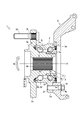
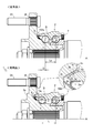
- the figure which shows the structure of the bearing device for wheels The figure which shows the state which attached the bearing device for wheels to the vehicle body.
- the wheel bearing device 1 rotatably supports the wheels.
- the wheel bearing device 1 includes an outer member 2, an inner member 3, and rolling members 4 and 5.
- the “inner side” refers to the vehicle body side of the wheel bearing device 1 when attached to the vehicle body
- the “outer side” refers to the wheel bearing device 1 when attached to the vehicle body. Indicates the wheel side.
- the “radial direction outer side” represents a direction away from the rotation axis A of the inner member 3, and the “radial direction inner side” represents a direction closer to the rotation axis A of the inner member 3.
- the “axial direction” represents the direction along the rotation axis A.
- the outer member 2 constitutes the outer ring portion of the rolling bearing structure.
- a fitting surface 2 a is formed on the inner periphery of the outer member 2 at the inner end.
- a fitting surface 2b is formed on the inner periphery of the outer end of the outer member 2.
- two outer raceway surfaces 2c and 2d are formed on the inner periphery of the outer member 2 at the central portion in the axial direction.
- the outer member 2 is formed with a vehicle body mounting flange 2e extending radially outward from the outer peripheral surface thereof.
- the vehicle body mounting flange 2e is provided with a plurality of bolt holes 2f.
- the inner member 3 constitutes the inner ring portion of the rolling bearing structure.
- the inner member 3 includes a hub wheel 31 and an inner ring 32.
- the hub wheel 31 is arranged radially inside the outer member 2.
- a small-diameter step portion 3a is formed on the outer periphery of the inner end of the hub wheel 31 up to the central portion in the axial direction.
- the small-diameter step portion 3a indicates a portion where the outer diameter of the hub wheel 31 is small, and the outer peripheral surface thereof has a cylindrical shape with the rotation axis A as the center.
- the hub wheel 31 is formed with a spline hole 3b penetrating from the inner end portion to the outer end portion thereof.
- an inner raceway surface 3d is formed on the outer periphery of the hub wheel 31 at the central portion in the axial direction.
- the hub wheel 31 is formed with a wheel mounting flange 3e extending radially outward from the outer peripheral surface thereof.
- the wheel mounting flange 3e is provided with a plurality of bolt holes 3f centered on the rotation axis A, and the hub bolts 33 are press-fitted into the respective bolt holes 3f.
- the inner ring 32 is fitted onto the small-diameter step portion 3a of the hub wheel 31.
- a fitting surface 3g is formed on the outer periphery of the inner ring 32 at the inner end.
- An inner raceway surface 3c is formed on the outer periphery adjacent to the fitting surface 3g. Thereby, the inner raceway surface 3c is formed on the outer circumference of the inner ring 32.
- the rolling members 4 and 5 form the rolling portion of the rolling bearing structure.
- the rolling members 4 and 5 are so-called steel balls, and the rolling members 4 and 5 are arranged at equal intervals on the circumference by a cage.
- the inner rolling member 4 is interposed between the outer raceway surface 2c of the outer member 2 and the inner raceway surface 3c of the inner ring 32.
- the outer-side rolling member 5 is interposed between the outer raceway surface 2d of the outer member 2 and the inner raceway surface 3d of the hub wheel 31.
- both the rolling members 4 and 5 are spherical, but either one or both may be cylindrical or conical.
- the wheel bearing device 1 is configured such that the pilot portion 2g having a cylindrical shape is fitted into the fitting hole 9a of the knuckle 9 and the end surface of the vehicle body mounting flange 2e is brought into contact with the end surface of the knuckle 9 with the knuckle bolt 91 interposed therebetween. Can be installed. At this time, the knuckle bolt 91 is inserted from the inner side into the bolt hole 9b of the knuckle 9 and screwed into the bolt hole 2f of the vehicle body mounting flange 2e. Alternatively, the bolt holes 2f of the vehicle body mounting flange 2e are inserted from the outer side and screwed into the bolt holes 9b of the knuckle 9. Note that the bending moment M acts on the inner member 3 when the vehicle body turns or when the wheels are bumped over.
- FIG. 4 shows a conventional wheel bearing device for comparison.
- the same members are designated by the same reference numerals.
- the wheel bearing device 1 includes a pair of seal members 6 and 7 so as to close both open ends of the annular space S formed between the outer member 2 and the inner member 3 (the hub wheel 31 and the inner ring 32). ing.
- seal member 6 hereinafter referred to as “outer seal member” that closes the outer open end of the annular space S.
- the outer seal member 6 is made by vulcanizing and adhering an elastic member 62 to a core metal 61.
- the core metal 61 has a fitting portion 61a that is fitted into the fitting surface 2b of the outer member 2 and a side plate portion 61b that extends radially inward from the outer end of the fitting portion 61a. ..
- a side lip 62a is formed on the elastic member 62, and the tip edge of the side lip 62a is in contact with the flat end surface 3h.
- An intermediate lip 62b is formed radially inside the side lip 62a, and the tip edge of the intermediate lip 62b is in contact with the arc surface 3i.
- a grease lip 62c is formed on the elastic member 62, and the tip edge of the grease lip 62c is in contact with the shaft peripheral surface 3j.
- a ring-shaped recess 3m centering on the rotation axis A of the hub wheel 31 is provided at the inner side base end portion of the wheel mounting flange 3e of the hub wheel 31. ..
- the concave portion 3m is a portion that is recessed from the inner side end surface 3n of the wheel mounting flange 3e toward the outer side, and the flat end surface 3h that is the bottom surface thereof is perpendicular to the rotation axis A.
- an arcuate surface 3i which is an inner peripheral surface on the radially inner side of the recess 3m, is connected so as to be continuous with the flat end surface 3h and the shaft peripheral surface 3j.
- the shaft peripheral surface 3j is parallel to the rotation axis A outside the recess 3m. Then, at least the flat end surface 3h, the arcuate surface 3i, and the shaft peripheral surface 3j are subjected to polishing finishing. A reinforcing portion 3p that protrudes from the outer end surface 3o toward the outer side is provided at the outer base portion of the wheel mounting flange 3e. This is to prevent a decrease in strength due to the provision of the recess 3m.
- the outer side end portion 2i of the outer member 2 is inserted into the recess 3m (when it is inserted into the recess 3m beyond the two-dot chain line in the drawing). Exist). Then, at least a part of the outer seal member 6 fitted in the outer end 2i of the outer member 2 is housed inside the recess 3m (inside the two-dot chain line in the drawing, inside the recess 3m). Fits in). More specifically, a part of the outer seal member 6 including the side lip 62a and the intermediate lip 62b is accommodated in the recess 3m. However, in addition to the side lip 62a and the intermediate lip 62b, a part including the grease lip 62c may be housed inside the recess 3m. In this respect, “at least a part of the outer seal member 6" is not limited.
- the bearing device 1 for the present wheel has the outer member 2 expanded in the axial direction as compared with the conventional bearing device for a wheel.
- a space for accommodating the outer seal member 6 is secured inside the outer member 2. Therefore, in the present wheel bearing device 1, the relative distance L between the inner rolling member 4 and the outer rolling member 5 can be made larger than the relative distance Lp of the conventional wheel bearing device.
- the difference between the relative distance L and the relative distance Lp is represented by a value D.
- the bearing device 1 for a wheel of the present invention has a complicated and intricate shape compared with the clearance 103q of the bearing device for a wheel which is a conventional product. By doing so, muddy water flowing along the wheel mounting flange 3e and muddy water flowing along the outer member 2 are less likely to enter the gap 3q. Moreover, it becomes difficult for muddy water to reach the outer seal member 6.
- FIG. 1 In FIG. 1
- the dimension from the inclined surface 3k which is the radially outer inner peripheral surface of the recess 3m to the outer peripheral surface 2k of the outer end 2i of the outer member 2 is represented by a value d1.
- the value d1 is 0.1 mm or more even when the vehicle body is turning.
- the dimension from the flat end surface 3h, which is the bottom surface of the recess 3m, to the outer end surface 2h of the outer member 2 is represented by a value d2.
- the value d2 is 0.5 mm or more even when the vehicle body is turning.
- the annular recessed portion 3m centering on the rotation axis A of the hub wheel 31 is provided at the inner side base end portion of the wheel mounting flange 3e of the hub wheel 31. It is provided.
- the outer end 2i of the outer member 2 is inserted into the recess 3m, and at least part of the outer seal member 6 is housed in the recess 3m.
- the rigidity with respect to the bending moment M is increased, so that the bearing life can be improved.
- the wheel mounting flange 3e since the gap 3q formed by the inner side base end portion of the wheel mounting flange 3e and the outer side end portion 2i of the outer member 2 becomes complicated, the wheel mounting flange 3e is It is possible to prevent the muddy water flowing along and the muddy water flowing along the outer member 2 from reaching the outer seal member 6. Therefore, it is possible to prevent the sealing property of the outer seal member 6 from being lowered, so that the life of the bearing can be improved.
- the relative distance L between the inner rolling member 4 and the outer rolling member 5 can be increased. Therefore, the rigidity with respect to the bending moment M is increased, so that the bearing life can be improved.
- the wheel bearing device 1 includes a slinger 7.
- the slinger 7 is formed by bending a steel plate and is fitted along the inner peripheral surface of the recess 3 m.
- the tip of the side lip 62a of the elastic member 62 is in contact with the flat end surface 7h. Further, the tip end edge of the intermediate lip 62b of the elastic member 62 is in contact with the arc surface 7i. Further, the grease lip 62c of the elastic member 62 has its tip edge in contact with the shaft peripheral surface 7j.
- the wheel bearing device 1 according to the second embodiment also has the same effects as the wheel bearing device 1 according to the first embodiment.
- a narrow gap 3q is formed by the inclined surface 3k which is the radially outer inner peripheral surface of the recess 3m and the outer peripheral surface 2k at the outer end 2i of the outer member 2. ing.
- the muddy water is collected by the narrow gap 3q, so that it becomes difficult for the muddy water to reach the outer seal member 6. That is, even if muddy water enters the gap 3q, it is possible to prevent the muddy water from passing through and prevent the muddy water from reaching the outer seal member 6.
- the gap 3q is defined as "labyrinth portion R".
- the labyrinth part R has a function of discharging the infiltrated muddy water. That is, the inclined surface 3k, which is the radially outer inner peripheral surface of the recess 3m, is inclined radially outward toward the inner side. Further, the outer peripheral surface 2k of the outer end 2i of the outer member 2 is also inclined radially outward toward the inner side. Therefore, the labyrinth portion R composed of the inclined surface 3k and the outer peripheral surface 2k is inclined radially outward toward the inner side. As a result, the muddy water remaining in the labyrinth portion R is rotated together with the rotation of the hub wheel 31. Then, the muddy water is subjected to a centrifugal force outward in the radial direction. Thus, the muddy water is discharged to the outside from the labyrinth portion R (see arrow F).
- the labyrinth portion R is formed by the inner peripheral surface of the recess 3m and the outer peripheral surface 2k of the outer end 2i of the outer member 2 being close to each other. According to the wheel bearing device 1, even if muddy water enters the labyrinth portion R, it is possible to prevent the muddy water from passing through and prevent the muddy water from reaching the outer seal member 6. Therefore, it is possible to prevent the sealing property of the outer seal member 6 from being lowered, so that the life of the bearing can be improved.
- the labyrinth portion R is inclined outward in the radial direction toward the inner side. According to the wheel bearing device 1, even if muddy water enters the labyrinth portion R, it can be discharged by utilizing the centrifugal force generated by the rotation of the hub wheel 31. Therefore, it is possible to further suppress the deterioration of the sealing performance of the outer seal member 6.
- the outer member 2 has the vehicle body mounting flange 2e
- the inner member 3 has the hub wheel 31 and the inner ring 32 having the wheel mounting flange 3e.
- It is a third generation structure, but is not limited to this.
- it may be a second generation structure in which the outer member has a vehicle body mounting flange and the hub wheel having the wheel mounting flange can be inserted into the inner ring which is the inner member.
- it may be a fourth generation structure in which the outer member has a vehicle body mounting flange and the inner member is a fitting body of a hub wheel having a wheel mounting flange and a universal joint.
- the present invention can be applied to a wheel bearing device.
Landscapes
- Engineering & Computer Science (AREA)
- General Engineering & Computer Science (AREA)
- Mechanical Engineering (AREA)
- Rolling Contact Bearings (AREA)
- Sealing Of Bearings (AREA)
- Sealing Using Fluids, Sealing Without Contact, And Removal Of Oil (AREA)
Abstract
曲げモーメントに対する剛性を高めると共にアウター側シール部材の密封性の低下を抑えることで軸受寿命の向上を実現できる車輪用軸受装置を提供することを課題とする。複列の外側軌道面(2c)・(2d)を有する外方部材(2)と、ハブ輪(31)及び内輪(32)からなり、複列の内側軌道面(3c)・(3d)を有する内方部材(3)と、外方部材(2)と内方部材(3)のそれぞれの軌道面(2c)・(2d)・(3c)・(3d)間に介装される複列の転動部材(4)・(5)と、外方部材(2)と内方部材(3)によって形成された環状空間(S)のアウター側開口端を塞ぐアウター側シール部材(6)と、を備えた車輪用軸受装置(1)において、ハブ輪(31)における車輪取付フランジ(3e)のインナー側基端部分にハブ輪(31)の回転軸(A)を中心とする円環状の凹部(3m)が設けられており、外方部材(2)のアウター側端部(2i)が凹部(3m)に挿入され、かつアウター側シール部材(6)の少なくとも一部が凹部(3m)に収まっている。
Description
本発明は、車輪用軸受装置に関する。
車輪を回転自在に支持する車輪用軸受装置が知られている(特許文献1参照)。車輪用軸受装置では、外方部材の内側に内方部材が配置され、外方部材と内方部材のそれぞれの軌道面間に転動部材が介装されている。こうして、車輪用軸受装置は、転がり軸受構造を構成し、内方部材に取り付けられた車輪を回転自在としている。
ところで、車輪用軸受装置の外方部材と内方部材の間には、環状空間が形成され、当該環状空間のアウター側開口端を塞ぐシール部材が設けられている(図6参照)。このような車輪用軸受装置においては、外方部材の内側にシール部材を収容するためのスペースを確保する必要があり、結果としてインナー側の転動部材とアウター側の転動部材の相対距離が短くなってしまうという問題があった。従って、曲げモーメントに対する剛性が低下し、ひいては軸受寿命が短くなってしまうという問題があった。
加えて、内方部材を構成するハブ輪には、車輪取付フランジが形成されている(図6参照)。そして、この車輪取付フランジが外方部材のアウター側端部から隙間をあけて配置されている。このような車輪用軸受装置においては、車輪取付フランジを伝って流れる泥水や外方部材を伝って流れる泥水が隙間を通ってシール部材に到達し、シール部材が泥水に含まれる異物を噛み込んで破損したり摩耗したりしてしまうという問題があった。従って、シール部材の密封性が低下するという問題があった。
曲げモーメントに対する剛性を高めると共にアウター側シール部材の密封性の低下を抑えることで軸受寿命の向上を実現できる車輪用軸受装置を提供する。
本発明の車輪用軸受装置においては、
複列の外側軌道面を有する外方部材と、
ハブ輪及び内輪からなり、複列の内側軌道面を有する内方部材と、
前記外方部材と前記内方部材のそれぞれの軌道面間に介装される複列の転動部材と、
前記外方部材と前記内方部材によって形成された環状空間のアウター側開口端を塞ぐアウター側シール部材と、を備えた車輪用軸受装置において、
前記ハブ輪における車輪取付フランジのインナー側基端部分に当該ハブ輪の回転軸を中心とする円環状の凹部が設けられており、
前記外方部材のアウター側端部が前記凹部に挿入され、かつ前記アウター側シール部材の少なくとも一部が前記凹部に収まっている、ことが好ましい。
複列の外側軌道面を有する外方部材と、
ハブ輪及び内輪からなり、複列の内側軌道面を有する内方部材と、
前記外方部材と前記内方部材のそれぞれの軌道面間に介装される複列の転動部材と、
前記外方部材と前記内方部材によって形成された環状空間のアウター側開口端を塞ぐアウター側シール部材と、を備えた車輪用軸受装置において、
前記ハブ輪における車輪取付フランジのインナー側基端部分に当該ハブ輪の回転軸を中心とする円環状の凹部が設けられており、
前記外方部材のアウター側端部が前記凹部に挿入され、かつ前記アウター側シール部材の少なくとも一部が前記凹部に収まっている、ことが好ましい。
本発明の車輪用軸受装置においては、
前記凹部の内周面と前記外方部材のアウター側端部における外周面が互いに近接してラビリンス部を構成している、ものである。
前記凹部の内周面と前記外方部材のアウター側端部における外周面が互いに近接してラビリンス部を構成している、ものである。
本発明の車輪用軸受装置においては、
前記ラビリンス部がインナー側に向かうにつれて径方向外側へ傾斜している、ものである。
前記ラビリンス部がインナー側に向かうにつれて径方向外側へ傾斜している、ものである。
本発明の効果として、以下に示すような効果を奏する。
本発明の車輪用軸受装置によれば、ハブ輪における車輪取付フランジのインナー側基端部分にハブ輪の回転軸を中心とする円環状の凹部が設けられている。そして、外方部材のアウター側端部が凹部に挿入され、かつアウター側シール部材の少なくとも一部が凹部に収まっている。かかる車輪用軸受装置によれば、外方部材を軸方向に拡張させ、かつ外方部材の内側にアウター側シール部材を収容するためのスペースを確保できるので、インナー側の転動部材とアウター側の転動部材の相対距離を長くすることができる。従って、曲げモーメントに対する剛性が高まるので、軸受寿命の向上を実現できる。また、かかる車輪用軸受装置によれば、車輪取付フランジのインナー側基端部分と外方部材のアウター側端部によって形成される隙間が複雑になるので、車輪取付フランジを伝って流れる泥水や外方部材を伝って流れる泥水がアウター側シール部材に到達するのを抑えることができる。従って、アウター側シール部材の密封性の低下を抑えられるので、軸受寿命の向上を実現できる。
本発明の車輪用軸受装置によれば、凹部の内周面と外方部材のアウター側端部における外周面が互いに近接してラビリンス部を構成している。かかる車輪用軸受装置によれば、ラビリンス部に泥水が浸入しても、泥水の通り抜けを防いでアウター側シール部材に到達するのを抑えることができる。従って、アウター側シール部材の密封性の低下を抑えられるので、軸受寿命の向上を実現できる。
本発明の車輪用軸受装置によれば、ラビリンス部がインナー側に向かうにつれて径方向外側へ傾斜している。かかる車輪用軸受装置によれば、ラビリンス部に泥水が浸入しても、ハブ輪の回転による遠心力を利用して排出することができる。従って、アウター側シール部材の密封性の低下を更に抑えられる。
まず、図1を用いて、車輪用軸受装置1の構造について説明する。
車輪用軸受装置1は、車輪を回転自在に支持するものである。車輪用軸受装置1は、外方部材2と、内方部材3と、転動部材4・5と、を備えている。なお、本明細書において、「インナー側」とは、車体に取り付けた際の車輪用軸受装置1の車体側を表し、「アウター側」とは、車体に取り付けた際の車輪用軸受装置1の車輪側を表す。また、「径方向外側」とは、内方部材3の回転軸Aから遠ざかる方向を表し、「径方向内側」とは、内方部材3の回転軸Aに近づく方向を表す。更に、「軸方向」とは、回転軸Aに沿う方向を表す。
外方部材2は、転がり軸受構造の外輪部分を構成するものである。外方部材2のインナー側端部における内周には、嵌合面2aが形成されている。また、外方部材2のアウター側端部における内周には、嵌合面2bが形成されている。更に、外方部材2の軸方向中央部における内周には、二つの外側軌道面2c・2dが形成されている。加えて、外方部材2には、その外周面から径方向外側へ延びる車体取付フランジ2eが形成されている。車体取付フランジ2eには、複数のボルト穴2fが設けられている。
内方部材3は、転がり軸受構造の内輪部分を構成するものである。内方部材3は、ハブ輪31と内輪32で構成されている。
ハブ輪31は、外方部材2の径方向内側に配置される。ハブ輪31のインナー側端部における外周には、軸方向中央部まで小径段部3aが形成されている。小径段部3aは、ハブ輪31の外径が小さくなった部分を指し、その外周面が回転軸Aを中心とする円筒形状となっている。また、ハブ輪31には、そのインナー側端部からアウター側端部まで貫かれたスプライン穴3bが形成されている。更に、ハブ輪31の軸方向中央部における外周には、内側軌道面3dが形成されている。加えて、ハブ輪31には、その外周面から径方向外側へ延びる車輪取付フランジ3eが形成されている。車輪取付フランジ3eには、回転軸Aを中心に複数のボルト穴3fが設けられており、それぞれのボルト穴3fにハブボルト33が圧入されている。
内輪32は、ハブ輪31の小径段部3aに外嵌される。内輪32のインナー側端部における外周には、嵌合面3gが形成されている。また、嵌合面3gに隣接する外周には、内側軌道面3cが形成されている。これにより、内輪32の外周に内側軌道面3cを構成している。
転動部材4・5は、転がり軸受構造の転動部分を構成するものである。転動部材4・5は、いわゆる鋼球であって、それぞれが保持器によって円周上に等間隔にならべられている。インナー側の転動部材4は、外方部材2の外側軌道面2cと内輪32の内側軌道面3cの間に介装されている。また、アウター側の転動部材5は、外方部材2の外側軌道面2dとハブ輪31の内側軌道面3dの間に介装されている。なお、本車輪用軸受装置1において、転動部材4・5は、両方とも球形状であるが、いずれか一方又は両方が円筒形状又は円錐形状であってもよい。
次に、図2を用いて、車輪用軸受装置1を車体に取り付けるための構造について説明する。
車輪用軸受装置1は、円筒形状であるパイロット部2gをナックル9の嵌合穴9aに嵌め込むと共に車体取付フランジ2eの端面をナックル9の端面に当接させた状態で、ナックルボルト91を介して取り付けられる。このとき、ナックルボルト91は、ナックル9のボルト穴9bにインナー側から挿通され、車体取付フランジ2eのボルト穴2fに螺合される。或いは、車体取付フランジ2eのボルト穴2fにアウター側から挿通され、ナックル9のボルト穴9bに螺合される。なお、車体旋回時や車輪の凹凸乗越時などで、内方部材3に曲げモーメントMがはたらくこととなる。
次に、図3及び図4を用いて、第一実施形態に係る車輪用軸受装置1の特徴点とその効果について説明する。図4には、比較対象として従来品である車輪用軸受装置を示している。ここでは、従来品である車輪用軸受装置についても、同じ部材については同じ符号を付すものとする。
まず、車輪用軸受装置1を構成するシール部材6について説明しておく。車輪用軸受装置1は、外方部材2と内方部材3(ハブ輪31及び内輪32)の間に形成される環状空間Sの両側開口端を塞ぐべく、一対のシール部材6・7を備えている。以下では、環状空間Sのアウター側開口端を塞ぐシール部材(以降「アウター側シール部材」という)6に着目して説明する。
アウター側シール部材6は、芯金61に弾性部材62を加硫接着したものである。芯金61は、外方部材2の嵌合面2bに内嵌される嵌合部61aと、嵌合部61aのアウター側端部から径方向内側へ延びる側板部61bと、を有している。弾性部材62には、サイドリップ62aが形成されており、サイドリップ62aの先端縁が平端面3hに接触している。また、サイドリップ62aの径方向内側には、中間リップ62bが形成されており、中間リップ62bの先端縁が円弧面3iに接触している。更に、弾性部材62には、グリースリップ62cが形成されており、グリースリップ62cの先端縁が軸周面3jに接触している。
第一実施形態に係る車輪用軸受装置1においては、ハブ輪31における車輪取付フランジ3eのインナー側基端部分にハブ輪31の回転軸Aを中心とする円環状の凹部3mが設けられている。凹部3mは、車輪取付フランジ3eのインナー側端面3nからアウター側へ向けて窪んだ部位であり、その底面である平端面3hが回転軸Aに対して垂直となっている。また、凹部3mの径方向内側の内周面である円弧面3iが平端面3h及び軸周面3jに対して連続するようにつながっている。更に、軸周面3jは、凹部3mの外側で回転軸Aに対して平行となっている。そして、少なくとも平端面3h、円弧面3i及び軸周面3jには研磨加工仕上げが施される。なお、車輪取付フランジ3eのアウター側基端部分には、アウター側端面3oからアウター側へ向けて突出する補強部3pが設けられている。これは、凹部3mを設けたことによる強度の低下を防ぐためである。
同時に、第一実施形態に係る車輪用軸受装置1においては、外方部材2のアウター側端部2iが凹部3mに挿入されている(図中の二点鎖線を越えて凹部3mに挿入されている)。そして、外方部材2のアウター側端部2iに内嵌されているアウター側シール部材6の少なくとも一部が凹部3mの内側に収まっている(図中の二点鎖線を越えて凹部3mの内側に収まっている)。具体的に説明すると、アウター側シール部材6のサイドリップ62aと中間リップ62bを含む一部が凹部3mに収まっている。但し、サイドリップ62aと中間リップ62bに加えてグリースリップ62cを含む一部が凹部3mの内側に収まっているとしてもよい。この点、「アウター側シール部材6の少なくとも一部」について限定するものではない。
このように、本車輪用軸受装置1は、従来品である車輪用軸受装置に比べて外方部材2を軸方向に拡張している。また、外方部材2の内側にアウター側シール部材6を収容するためのスペースを確保している。このため、本車輪用軸受装置1は、インナー側の転動部材4とアウター側の転動部材5の相対距離Lを従来品である車輪用軸受装置の相対距離Lpよりも大きくできるのである。図4において、相対距離Lと相対距離Lpの差異は値Dで表されている。
更に、本車輪用軸受装置1においては、車輪取付フランジ3eのインナー側基端部分と外方部材2のアウター側端部2iによって形成される隙間3qが凹部3mの内周面に沿って形成される。このため、本車輪用軸受装置1は、従来品である車輪用軸受装置の隙間103qに比べて複雑に入り組んだ形状となっている。このようにすることで、車輪取付フランジ3eを伝って流れる泥水や外方部材2を伝って流れる泥水が隙間3qに入りにくくなる。また、泥水がアウター側シール部材6まで到達しにくくなる。図3において、凹部3mの径方向外側の内周面である傾斜面3kから外方部材2のアウター側端部2iにおける外周面2kまでの寸法は値d1で表されている。値d1は、車体旋回時においても0.1mm以上とされる。更に、凹部3mの底面である平端面3hから外方部材2のアウター側端面2hまでの寸法は値d2で表されている。値d2は、車体旋回時においても0.5mm以上とされる。
以上のように、第一実施形態に係る車輪用軸受装置1は、ハブ輪31における車輪取付フランジ3eのインナー側基端部分にハブ輪31の回転軸Aを中心とする円環状の凹部3mが設けられている。そして、外方部材2のアウター側端部2iが凹部3mに挿入され、かつアウター側シール部材6の少なくとも一部が凹部3mに収まっている。かかる車輪用軸受装置1によれば、外方部材2を軸方向に拡張させ、かつ外方部材2の内側にアウター側シール部材6を収容するためのスペースを確保できるので、インナー側の転動部材4とアウター側の転動部材5の相対距離Lを長くすることができる。従って、曲げモーメントMに対する剛性が高まるので、軸受寿命の向上を実現できる。また、かかる車輪用軸受装置1によれば、車輪取付フランジ3eのインナー側基端部分と外方部材2のアウター側端部2iによって形成される隙間3qが複雑になるので、車輪取付フランジ3eを伝って流れる泥水や外方部材2を伝って流れる泥水がアウター側シール部材6に到達するのを抑えることができる。従って、アウター側シール部材6の密封性の低下を抑えられるので、軸受寿命の向上を実現できる。
加えて、本車輪用軸受装置1では、インナー側の転動部材4とアウター側の転動部材5の相対距離Lを長くすることができる。従って、曲げモーメントMに対する剛性が高まるので、軸受寿命の向上を実現できる。
次に、図5を用いて、第二実施形態に係る車輪用軸受装置1の特徴点とその効果について説明する。なお、第一実施形態に係る車輪用軸受装置1と比較して異なる部分に着目して説明する。
第二実施形態に係る車輪用軸受装置1においては、スリンガ7を具備している。スリンガ7は、鋼板を湾曲させて形成したものであり、凹部3mの内周面に沿うように嵌め込まれている。そして、弾性部材62のサイドリップ62aは、その先端縁が平端面7hに接触している。また、弾性部材62の中間リップ62bは、その先端縁が円弧面7iに接触している。更に、弾性部材62のグリースリップ62cは、その先端縁が軸周面7jに接触している。
第二実施形態に係る車輪用軸受装置1においても、第一実施形態に係る車輪用軸受装置1と同様の作用効果を奏する。
次に、図3から図6を用いて、各実施形態に係る車輪用軸受装置1の他の特徴点とその効果について説明する。
各実施形態に係る車輪用軸受装置1には、凹部3mの径方向外側の内周面である傾斜面3kと外方部材2のアウター側端部2iにおける外周面2kによって細い隙間3qが形成されている。これにより、泥水が細い隙間3qによって捕集されるため、泥水がアウター側シール部材6まで到達しにくくなる。つまり、隙間3qに泥水が浸入しても、泥水の通り抜けを防いでアウター側シール部材6に到達するのを抑えることができるのである。本明細書においては、かかる隙間3qを「ラビリンス部R」と定義する。
ところで、ラビリンス部Rは、浸入した泥水を排出する機能を有している。即ち、凹部3mの径方向外側の内周面である傾斜面3kは、インナー側に向かうにつれて径方向外側へ傾斜している。また、外方部材2のアウター側端部2iにおける外周面2kも、インナー側に向かうにつれて径方向外側へ傾斜している。従って、傾斜面3kと外周面2kでなるラビリンス部Rは、インナー側に向かうにつれて径方向外側へ傾斜している。これにより、ラビリンス部Rにとどまった泥水は、ハブ輪31の回転につられて共に回転するようになる。すると、かかる泥水には、径方向外側へ向かう遠心力がかかることとなる。こうして、泥水は、このラビリンス部Rから外部へ排出される(矢印F参照)。
以上のように、本車輪用軸受装置1は、凹部3mの内周面と外方部材2のアウター側端部2iにおける外周面2kが互いに近接してラビリンス部Rを構成している。かかる車輪用軸受装置1によれば、ラビリンス部Rに泥水が浸入しても、泥水の通り抜けを防いでアウター側シール部材6に到達するのを抑えることができる。従って、アウター側シール部材6の密封性の低下を抑えられるので、軸受寿命の向上を実現できる。
加えて、本車輪用軸受装置1は、ラビリンス部Rがインナー側に向かうにつれて径方向外側へ傾斜している。かかる車輪用軸受装置1によれば、ラビリンス部Rに泥水が浸入しても、ハブ輪31の回転による遠心力を利用して排出することができる。従って、アウター側シール部材6の密封性の低下を更に抑えられる。
最後に、本明細書に開示した車輪用軸受装置1は、外方部材2に車体取付フランジ2eを有し、内方部材3が車輪取付フランジ3eを有するハブ輪31と内輪32で構成された第3世代構造であるが、これに限定するものではない。例えば、外方部材に車体取付フランジを有し、内方部材である内輪に対して車輪取付フランジを有するハブ輪を挿通できる第2世代構造であってもよい。更に、外方部材に車体取付フランジを有し、内方部材が車輪取付フランジを有するハブ輪と自在継手の嵌合体である第4世代構造であってもよい。
本発明は、車輪用軸受装置に利用可能である。
1 車輪用軸受装置
2 外方部材、 2c 外側軌道面、 2d 外側軌道面、 2i アウター
側端部
3 内方部材、 3c 内側軌道面、 3d 内側軌道面、 3e 車輪取付
フランジ、 3m 凹部、 3q 隙間
31 ハブ輪
32 内輪
4 転動部材
5 転動部材
6 アウター側シール部材
A 回転軸
R ラビリンス部
S 環状空間
2 外方部材、 2c 外側軌道面、 2d 外側軌道面、 2i アウター
側端部
3 内方部材、 3c 内側軌道面、 3d 内側軌道面、 3e 車輪取付
フランジ、 3m 凹部、 3q 隙間
31 ハブ輪
32 内輪
4 転動部材
5 転動部材
6 アウター側シール部材
A 回転軸
R ラビリンス部
S 環状空間
Claims (3)
- 複列の外側軌道面を有する外方部材と、
ハブ輪及び内輪からなり、複列の内側軌道面を有する内方部材と、
前記外方部材と前記内方部材のそれぞれの軌道面間に介装される複列の転動部材と、
前記外方部材と前記内方部材によって形成された環状空間のアウター側開口端を塞ぐアウター側シール部材と、を備えた車輪用軸受装置において、
前記ハブ輪における車輪取付フランジのインナー側基端部分に当該ハブ輪の回転軸を中心とする円環状の凹部が設けられており、
前記外方部材のアウター側端部が前記凹部に挿入され、かつ前記アウター側シール部材の少なくとも一部が前記凹部に収まっている、ことを特徴とする車輪用軸受装置。 - 前記凹部の内周面と前記外方部材のアウター側端部における外周面が互いに近接してラビリンス部を構成している、ことを特徴とする請求項1に記載の車輪用軸受装置。
- 前記ラビリンス部がインナー側に向かうにつれて径方向外側へ傾斜している、ことを特徴とする請求項2に記載の車輪用軸受装置。
Priority Applications (3)
| Application Number | Priority Date | Filing Date | Title |
|---|---|---|---|
| DE112020000511.9T DE112020000511T5 (de) | 2019-01-25 | 2020-01-23 | Lagervorrichtung für Fahrzeugrad |
| US17/424,236 US12109841B2 (en) | 2019-01-25 | 2020-01-23 | Bearing device for vehicle wheel |
| CN202080009909.7A CN113302412A (zh) | 2019-01-25 | 2020-01-23 | 车轮用轴承装置 |
Applications Claiming Priority (2)
| Application Number | Priority Date | Filing Date | Title |
|---|---|---|---|
| JP2019011471A JP7365769B2 (ja) | 2019-01-25 | 2019-01-25 | 車輪用軸受装置 |
| JP2019-011471 | 2019-01-25 |
Publications (1)
| Publication Number | Publication Date |
|---|---|
| WO2020153419A1 true WO2020153419A1 (ja) | 2020-07-30 |
Family
ID=71736446
Family Applications (1)
| Application Number | Title | Priority Date | Filing Date |
|---|---|---|---|
| PCT/JP2020/002268 Ceased WO2020153419A1 (ja) | 2019-01-25 | 2020-01-23 | 車輪用軸受装置 |
Country Status (5)
| Country | Link |
|---|---|
| US (1) | US12109841B2 (ja) |
| JP (1) | JP7365769B2 (ja) |
| CN (1) | CN113302412A (ja) |
| DE (1) | DE112020000511T5 (ja) |
| WO (1) | WO2020153419A1 (ja) |
Citations (5)
| Publication number | Priority date | Publication date | Assignee | Title |
|---|---|---|---|---|
| JP2003240003A (ja) * | 2002-02-18 | 2003-08-27 | Nsk Ltd | 軸受用シール、シール付軸受およびハブユニット軸受 |
| KR20130087855A (ko) * | 2012-01-30 | 2013-08-07 | 주식회사 일진글로벌 | 휠 베어링의 씰링장치 |
| US20140037239A1 (en) * | 2012-07-09 | 2014-02-06 | Aktiebolaget Skf | Hub bearing assembly with a sealing device |
| JP2015148253A (ja) * | 2014-02-05 | 2015-08-20 | Ntn株式会社 | 車輪用軸受装置 |
| JP2016003709A (ja) * | 2014-06-17 | 2016-01-12 | Ntn株式会社 | 車輪用軸受装置 |
Family Cites Families (12)
| Publication number | Priority date | Publication date | Assignee | Title |
|---|---|---|---|---|
| JP2006137297A (ja) | 2004-11-12 | 2006-06-01 | Ntn Corp | 車輪用軸受装置 |
| JP5301175B2 (ja) | 2008-02-29 | 2013-09-25 | Ntn株式会社 | 駆動車輪用軸受装置 |
| JP5327590B2 (ja) * | 2008-09-12 | 2013-10-30 | 株式会社ジェイテクト | 転がり軸受装置 |
| WO2012043706A1 (ja) * | 2010-09-30 | 2012-04-05 | Ntn株式会社 | 車輪用軸受装置およびその製造方法 |
| JP5776251B2 (ja) * | 2011-03-24 | 2015-09-09 | 株式会社ジェイテクト | 車両用軸受装置 |
| JP6111740B2 (ja) * | 2012-04-25 | 2017-04-12 | 日本精工株式会社 | 車輪支持用転がり軸受ユニット |
| DE102014204334A1 (de) * | 2014-03-10 | 2015-09-10 | Schaeffler Technologies AG & Co. KG | Radlagereinheit |
| JP6550219B2 (ja) * | 2014-08-06 | 2019-07-24 | Ntn株式会社 | 車輪用軸受装置 |
| JP2017145881A (ja) | 2016-02-17 | 2017-08-24 | 内山工業株式会社 | 密封装置 |
| DE102017200338A1 (de) * | 2017-01-11 | 2017-04-27 | Audi Ag | Radlager für ein Kraftfahrzeug |
| JP6848666B2 (ja) * | 2017-05-12 | 2021-03-24 | 日本精工株式会社 | ハブユニット軸受 |
| DE102018105560B4 (de) * | 2017-12-15 | 2019-09-05 | Schaeffler Technologies AG & Co. KG | Dichtungsanordnung eines Radlagers |
-
2019
- 2019-01-25 JP JP2019011471A patent/JP7365769B2/ja active Active
-
2020
- 2020-01-23 WO PCT/JP2020/002268 patent/WO2020153419A1/ja not_active Ceased
- 2020-01-23 DE DE112020000511.9T patent/DE112020000511T5/de active Pending
- 2020-01-23 CN CN202080009909.7A patent/CN113302412A/zh active Pending
- 2020-01-23 US US17/424,236 patent/US12109841B2/en active Active
Patent Citations (5)
| Publication number | Priority date | Publication date | Assignee | Title |
|---|---|---|---|---|
| JP2003240003A (ja) * | 2002-02-18 | 2003-08-27 | Nsk Ltd | 軸受用シール、シール付軸受およびハブユニット軸受 |
| KR20130087855A (ko) * | 2012-01-30 | 2013-08-07 | 주식회사 일진글로벌 | 휠 베어링의 씰링장치 |
| US20140037239A1 (en) * | 2012-07-09 | 2014-02-06 | Aktiebolaget Skf | Hub bearing assembly with a sealing device |
| JP2015148253A (ja) * | 2014-02-05 | 2015-08-20 | Ntn株式会社 | 車輪用軸受装置 |
| JP2016003709A (ja) * | 2014-06-17 | 2016-01-12 | Ntn株式会社 | 車輪用軸受装置 |
Also Published As
| Publication number | Publication date |
|---|---|
| JP2020118257A (ja) | 2020-08-06 |
| DE112020000511T5 (de) | 2021-11-25 |
| US12109841B2 (en) | 2024-10-08 |
| CN113302412A (zh) | 2021-08-24 |
| US20220065289A1 (en) | 2022-03-03 |
| JP7365769B2 (ja) | 2023-10-20 |
Similar Documents
| Publication | Publication Date | Title |
|---|---|---|
| CN107405951B (zh) | 车轮轴承装置 | |
| US7832941B2 (en) | Bearing apparatus for a wheel of vehicle | |
| JP6587851B2 (ja) | 車輪用軸受装置 | |
| US7175349B2 (en) | Wheel rotation supporting apparatus | |
| JP7119992B2 (ja) | ハブユニット軸受 | |
| US8746985B2 (en) | Rolling bearing device for wheel | |
| JP2008173995A (ja) | 車輪用軸受装置 | |
| WO2024185760A1 (ja) | 車輪用軸受装置 | |
| JP7365769B2 (ja) | 車輪用軸受装置 | |
| JP2003056577A (ja) | 車軸用軸受装置 | |
| JP2011051474A (ja) | 車輪用軸受装置 | |
| JP2008101685A (ja) | 車輪用軸受装置およびその製造方法 | |
| JP2020159399A (ja) | 車輪用軸受装置 | |
| JP2006137297A (ja) | 車輪用軸受装置 | |
| JP6348309B2 (ja) | 車輪用軸受装置およびその外方部材の製造方法 | |
| JP6968044B2 (ja) | 車輪用軸受装置 | |
| JP2022147755A (ja) | 車輪用軸受装置 | |
| JP7007924B2 (ja) | 車輪用軸受装置 | |
| WO2022185382A1 (ja) | 車輪用軸受装置 | |
| JP2004306681A (ja) | 車輪支持用転がり軸受ユニット | |
| JPH10181304A (ja) | 車輪用ハブユニット軸受 | |
| JP5236097B2 (ja) | 車輪用軸受装置 | |
| JP2011111010A (ja) | 車輪用軸受装置 | |
| JP5024850B2 (ja) | 車輪用軸受装置 | |
| WO2011034135A1 (ja) | 車輪用軸受装置 |
Legal Events
| Date | Code | Title | Description |
|---|---|---|---|
| 121 | Ep: the epo has been informed by wipo that ep was designated in this application |
Ref document number: 20744246 Country of ref document: EP Kind code of ref document: A1 |
|
| 122 | Ep: pct application non-entry in european phase |
Ref document number: 20744246 Country of ref document: EP Kind code of ref document: A1 |