WO2020153394A1 - 摺動部材、摺動部材の製造方法および摺動システム - Google Patents
摺動部材、摺動部材の製造方法および摺動システム Download PDFInfo
- Publication number
- WO2020153394A1 WO2020153394A1 PCT/JP2020/002077 JP2020002077W WO2020153394A1 WO 2020153394 A1 WO2020153394 A1 WO 2020153394A1 JP 2020002077 W JP2020002077 W JP 2020002077W WO 2020153394 A1 WO2020153394 A1 WO 2020153394A1
- Authority
- WO
- WIPO (PCT)
- Prior art keywords
- sliding
- sliding member
- polymer monolith
- member according
- base material
- Prior art date
- Legal status (The legal status is an assumption and is not a legal conclusion. Google has not performed a legal analysis and makes no representation as to the accuracy of the status listed.)
- Ceased
Links
Images





Classifications
-
- B—PERFORMING OPERATIONS; TRANSPORTING
- B32—LAYERED PRODUCTS
- B32B—LAYERED PRODUCTS, i.e. PRODUCTS BUILT-UP OF STRATA OF FLAT OR NON-FLAT, e.g. CELLULAR OR HONEYCOMB, FORM
- B32B27/00—Layered products comprising a layer of synthetic resin
- B32B27/38—Layered products comprising a layer of synthetic resin comprising epoxy resins
-
- B—PERFORMING OPERATIONS; TRANSPORTING
- B32—LAYERED PRODUCTS
- B32B—LAYERED PRODUCTS, i.e. PRODUCTS BUILT-UP OF STRATA OF FLAT OR NON-FLAT, e.g. CELLULAR OR HONEYCOMB, FORM
- B32B5/00—Layered products characterised by the non- homogeneity or physical structure, i.e. comprising a fibrous, filamentary, particulate or foam layer; Layered products characterised by having a layer differing constitutionally or physically in different parts
- B32B5/18—Layered products characterised by the non- homogeneity or physical structure, i.e. comprising a fibrous, filamentary, particulate or foam layer; Layered products characterised by having a layer differing constitutionally or physically in different parts characterised by features of a layer of foamed material
-
- C—CHEMISTRY; METALLURGY
- C08—ORGANIC MACROMOLECULAR COMPOUNDS; THEIR PREPARATION OR CHEMICAL WORKING-UP; COMPOSITIONS BASED THEREON
- C08J—WORKING-UP; GENERAL PROCESSES OF COMPOUNDING; AFTER-TREATMENT NOT COVERED BY SUBCLASSES C08B, C08C, C08F, C08G or C08H
- C08J9/00—Working-up of macromolecular substances to porous or cellular articles or materials; After-treatment thereof
- C08J9/26—Working-up of macromolecular substances to porous or cellular articles or materials; After-treatment thereof by elimination of a solid phase from a macromolecular composition or article, e.g. leaching out
-
- C—CHEMISTRY; METALLURGY
- C23—COATING METALLIC MATERIAL; COATING MATERIAL WITH METALLIC MATERIAL; CHEMICAL SURFACE TREATMENT; DIFFUSION TREATMENT OF METALLIC MATERIAL; COATING BY VACUUM EVAPORATION, BY SPUTTERING, BY ION IMPLANTATION OR BY CHEMICAL VAPOUR DEPOSITION, IN GENERAL; INHIBITING CORROSION OF METALLIC MATERIAL OR INCRUSTATION IN GENERAL
- C23C—COATING METALLIC MATERIAL; COATING MATERIAL WITH METALLIC MATERIAL; SURFACE TREATMENT OF METALLIC MATERIAL BY DIFFUSION INTO THE SURFACE, BY CHEMICAL CONVERSION OR SUBSTITUTION; COATING BY VACUUM EVAPORATION, BY SPUTTERING, BY ION IMPLANTATION OR BY CHEMICAL VAPOUR DEPOSITION, IN GENERAL
- C23C26/00—Coating not provided for in groups C23C2/00 - C23C24/00
-
- F—MECHANICAL ENGINEERING; LIGHTING; HEATING; WEAPONS; BLASTING
- F16—ENGINEERING ELEMENTS AND UNITS; GENERAL MEASURES FOR PRODUCING AND MAINTAINING EFFECTIVE FUNCTIONING OF MACHINES OR INSTALLATIONS; THERMAL INSULATION IN GENERAL
- F16C—SHAFTS; FLEXIBLE SHAFTS; ELEMENTS OR CRANKSHAFT MECHANISMS; ROTARY BODIES OTHER THAN GEARING ELEMENTS; BEARINGS
- F16C33/00—Parts of bearings; Special methods for making bearings or parts thereof
- F16C33/02—Parts of sliding-contact bearings
- F16C33/04—Brasses; Bushes; Linings
- F16C33/06—Sliding surface mainly made of metal
- F16C33/12—Structural composition; Use of special materials or surface treatments, e.g. for rust-proofing
-
- F—MECHANICAL ENGINEERING; LIGHTING; HEATING; WEAPONS; BLASTING
- F16—ENGINEERING ELEMENTS AND UNITS; GENERAL MEASURES FOR PRODUCING AND MAINTAINING EFFECTIVE FUNCTIONING OF MACHINES OR INSTALLATIONS; THERMAL INSULATION IN GENERAL
- F16C—SHAFTS; FLEXIBLE SHAFTS; ELEMENTS OR CRANKSHAFT MECHANISMS; ROTARY BODIES OTHER THAN GEARING ELEMENTS; BEARINGS
- F16C33/00—Parts of bearings; Special methods for making bearings or parts thereof
- F16C33/02—Parts of sliding-contact bearings
- F16C33/04—Brasses; Bushes; Linings
- F16C33/06—Sliding surface mainly made of metal
- F16C33/14—Special methods of manufacture; Running-in
-
- F—MECHANICAL ENGINEERING; LIGHTING; HEATING; WEAPONS; BLASTING
- F16—ENGINEERING ELEMENTS AND UNITS; GENERAL MEASURES FOR PRODUCING AND MAINTAINING EFFECTIVE FUNCTIONING OF MACHINES OR INSTALLATIONS; THERMAL INSULATION IN GENERAL
- F16C—SHAFTS; FLEXIBLE SHAFTS; ELEMENTS OR CRANKSHAFT MECHANISMS; ROTARY BODIES OTHER THAN GEARING ELEMENTS; BEARINGS
- F16C33/00—Parts of bearings; Special methods for making bearings or parts thereof
- F16C33/02—Parts of sliding-contact bearings
- F16C33/04—Brasses; Bushes; Linings
- F16C33/20—Sliding surface consisting mainly of plastics
Definitions
- the present invention relates to a sliding member, a sliding member manufacturing method, and a sliding system.
- a surface of a base material as a base material on a sliding side with a mating member is subjected to texturing such as striation processing before use. There is.
- Patent Document 2 a curable composition containing a curable resin, a curing agent, a porogen, and a thickening agent is applied onto a substrate, the applied material formed by the application is cured, and An invention relating to a method for producing a porous monolith coating structure in which a porous monolith coating film is retained on the surface of a substrate by removing the porogen in the formed cured coating film is described. According to the invention relating to Patent Document 2, it is possible to form a porous monolith coating structure having a non-porous skin layer not formed on the surface thereof on a substrate without undergoing a step such as polishing. Have been described.
- sliding members such as plain bearings are used after they have been made compatible with the mating member.
- the familiarization process is a process in which the sliding member and the mating member are slid in advance to make the sliding surfaces of the two uniform.
- the familiarizing process is often performed with lubricating oil interposed between the sliding member and the mating member, but the familiarizing process should be performed even under poor lubrication conditions where the supply of lubricating oil is small. There is also. Under such poor lubrication conditions, the sliding member and the mating member were likely to come into direct contact with each other during the running-in process, and the temperature of the sliding member suddenly increased and seizure was likely to occur.
- sliding members such as sliding bearings that have been known in the past had room for further improvement in conformability.
- Patent Document 2 describes an invention related to a porous monolith coating structure, but does not describe a sliding member.
- an object of the present invention is to provide a sliding member excellent in conformability, a method for manufacturing the sliding member, and a sliding system.
- the present invention provides the following.
- ⁇ 1> A sliding member in which a polymer monolith is formed on the sliding surface of a base material having a surface roughness Ra of 0.5 to 1000 ⁇ m on the sliding surface with a mating member.
- ⁇ 3> The sliding member according to ⁇ 1> or ⁇ 2>, wherein the polymer skeleton of the polymer monolith is a polymer of a bifunctional or higher functional epoxy compound and a bifunctional or higher functional amine compound.
- ⁇ 4> The sliding member according to any one of ⁇ 1> to ⁇ 3>, wherein the porosity of the polymer monolith is 30% or more.
- ⁇ 5> The sliding member according to any one of ⁇ 1> to ⁇ 4>, wherein the polymer monolith has an average pore diameter of 0.01 to 100 ⁇ m.
- ⁇ 6> The sliding member according to any one of ⁇ 1> to ⁇ 5>, wherein the polymer monolith further contains silica particles.
- ⁇ 7> The sliding member according to any one of ⁇ 1> to ⁇ 6>, wherein the base material is a metal base material.
- Concavities and convexities are formed on the surface of the base material on the sliding side to have a surface roughness Ra of 0.5 to 1000 ⁇ m.
- ⁇ 9> The polymer monolith is provided in at least a part of the concave portion on the sliding side surface of the substrate, and at least a part of the sliding side surface of the substrate is exposed from the polymer monolith.
- ⁇ 10> The sliding member according to any one of ⁇ 1> to ⁇ 9>, in which a striation is formed on a surface of the base material on the sliding side.
- ⁇ 11> The sliding member according to any one of ⁇ 1> to ⁇ 10>, in which the polymer monolith has a maximum film thickness of 2000 ⁇ m or less.
- ⁇ 12> The sliding member according to any one of ⁇ 1> to ⁇ 11>, wherein the sliding member is a slide bearing.
- a method for producing a sliding member wherein a composition for forming a monolith is applied to form a coating film, the coating film is cured, and the pore-forming agent is removed from the cured film formed by curing to form a polymer monolith. .. ⁇ 14> Concavities and convexities are formed on the sliding side surface of the base material so that the surface roughness Ra is 0.5 to 1000 ⁇ m.
- the method for producing a sliding member according to ⁇ 13> wherein the polymer monolith is formed in at least a part of the concave portion of the surface of the base material on the sliding side.
- the polymer monolith is formed in at least a part of the concave portion of the sliding side surface of the substrate, and at least a part of the sliding side surface of the substrate is exposed from the polymer monolith.
- ⁇ 13> The method for producing a sliding member as described above.
- ⁇ 16> The production of the sliding member according to any one of ⁇ 13> to ⁇ 15>, wherein the polymerizable compound is a bifunctional or higher functional epoxy compound, and the crosslinking agent is a bifunctional or higher functional amine compound.
- ⁇ 17> The method for producing a sliding member according to any one of ⁇ 13> to ⁇ 16>, wherein the polymer monolith-forming composition further contains silica particles.
- the composition for forming a polymer monolith further contains an organic solvent having a boiling point of 100° C. or less.
- plain bearings A rotating shaft provided on the inner peripheral surface side of the sliding bearing, A sliding system comprising: a lubricating oil interposed between the sliding shaft and the rotating shaft, A sliding system in which the plain bearing is the sliding member according to any one of ⁇ 1> to ⁇ 12>.
- the present invention can provide a sliding member excellent in conformability, a method for manufacturing the sliding member, and a sliding system.
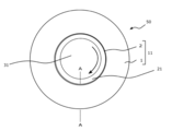
- FIG. 7 is a sectional view of the plain bearing 11 of FIG. 6 taken along the line AA.
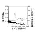
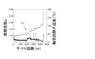
- FIG. 8 is a test result of Test Example 1, showing a change in friction coefficient and temperature of a bearing test piece using the sliding member of Example 1.
- 4 is a test result of Test Example 1, showing a change in friction coefficient and temperature of a bearing test piece using the sliding member of Comparative Example 1.
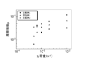
- 4 is a test result of Test Example 1, showing a change in friction coefficient and temperature of a bearing test piece using the sliding member of Comparative Example 2. It is a test result of Test Example 1, and is a Stribeck curve of Example 1, Comparative Example 1, and Comparative Example 2.
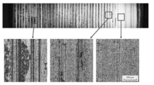
- FIG. 4 is a view of a test result of Test Example 1, showing a sliding surface of a bearing test piece using the sliding member of Example 1 after the test.
- FIG. 6 is a view of the test result of Test Example 1, showing a sliding surface of a bearing test piece using the sliding member of Comparative Example 1 after the test.
- FIG. 1 is a test result of Test Example 1, showing a sliding surface of a bearing test piece using the sliding member of Comparative Example 1 after the test.
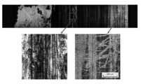
- Example 8 is a view of a sliding surface after a test of a bearing test piece using the sliding member of Comparative Example 2, which is a test result of Test Example 1.
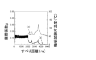
- 5 is a test result of Test Example 2, showing the change in friction coefficient and temperature of the bearing test pieces of Example 1 and Comparative Example 1. It is a test result of Test Example 2, and is a Stribeck curve of Example 1 and Comparative Example 1. It is a test result of Test Example 3, and is a Stribeck curve of Example 11, Example 12, and Comparative Example 11.
- a numerical range represented by using a symbol “to” means a range including the numerical values before and after “to” as a lower limit value and an upper limit value, respectively.
- (meth)acrylate means both “acrylate” and “methacrylate” or either
- (meth)acrylic means both “acrylic” and “methacrylic”, or , Which means either.
- the sliding member of the present invention is a sliding member in which a polymer monolith is formed on the sliding-side surface of a base material having a surface roughness Ra of 0.5-1000 ⁇ m on the sliding-side surface with a mating member. It is characterized by
- the sliding member of the present invention can suppress the occurrence of seizure by suppressing a sudden increase in the temperature of the sliding member during the familiarizing process. Further, even if the load and the sliding speed (sliding speed) change during the running-in process, a sharp increase in the friction coefficient can be suppressed, and the running-in process can be stably performed.
- the sliding member of the present invention has excellent conformability, is free from seizure, and can form a favorable conforming surface in a short time. The reason why such an effect is obtained is supposed to be as follows.
- the sliding member of the present invention has the polymer monolith on the surface of the base material, but since the polymer monolith has a three-dimensional bicontinuous structure of continuous pores and polymer skeleton, it has high flexibility, It is easy to keep the lubricating oil inside efficiently. Since such a polymer monolith is formed on the sliding-side surface of the base material whose surface roughness Ra on the sliding side is 0.5 to 1000 ⁇ m, friction with the mating member at the time of running-in treatment is achieved. The coefficient can be kept low. Further, even if a strong load is applied to the sliding surface with the mating member during the fitting-in process, it is possible to suppress a sudden increase in the temperature of the sliding member and suppress the occurrence of seizure. Further, it is possible to suppress a sudden change in the friction coefficient.
- the conforming treatment gradually progresses, the projections on the sliding side surface of the base material (hereinafter, also referred to as sliding surface) are worn and the sliding surface is gradually flattened, and the polymer monolith is gradually
- the conforming treatment proceeds with the polymer monolith remaining in the recesses of the sliding surface even when the conforming treatment has progressed to some extent. Therefore, it is presumed that the polymer monolith can maintain the excellent effect of improving the frictional characteristics and the effect of suppressing seizure even at a stage where the familiarization treatment has progressed to some extent.
- the sliding member of the present invention is presumed to have excellent conformability.
- the sliding member of the present invention is also excellent in impact resistance.
- the polymer monolith may remain in the recesses on the sliding surface of the base material even after the running-in treatment.
- the polymer monolith can provide excellent lubrication characteristics and excellent impact resistance.
- the sliding member of the present invention when texturing such as striation processing was performed on the sliding surface of the base material, highly sophisticated polishing processing was performed, but according to the sliding member of the present invention, by forming a polymer monolith. Further, excellent conformability can be obtained without performing high-level polishing (for example, only primary machining), and the manufacturing cost of the sliding member can be reduced. Needless to say, the sliding member of the present invention may be one in which the sliding surface of the base material is highly polished.
- the sliding member of the present invention even when the running-in process is performed under poor lubrication conditions in which the supply of lubricating oil is small, the temperature of the sliding member suddenly rises and the friction coefficient rapidly increases. Fluctuations can be suppressed. It is presumed that the reason why such an effect is obtained is that the polymer monolith easily holds the lubricating oil effectively inside.
- the sliding member of the present invention even when the running-in process is performed by intermittent operation such as repeated start and stop, the temperature of the sliding member is suddenly increased and the friction coefficient is increased. It is possible to suppress abrupt changes and form a good conforming surface.
- the reason why such an effect is obtained is that, as described above, the polymer monolith easily retains the lubricating oil inside effectively, and therefore the driving stop of the device is stopped due to the effect of the polymer monolith holding the lubricating oil inside. It is presumed that this is because it is possible to avoid problems such as burn-in due to running out of oil.
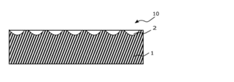
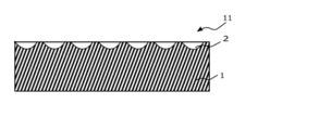
- FIG. 1 is a diagram showing an embodiment of a sliding member.
- Reference numeral 1 is a base material
- reference numeral 2 is a polymer monolith
- reference numeral 10 is a sliding member.
- the material of the base material 1 is not particularly limited.
- a metal, a resin, an inorganic material, etc. may be mentioned.
- the metal include iron, aluminum, copper and alloys containing these metal atoms.
- the resin include polyacetal resin, polyamide resin, polyimide resin, polycarbonate resin, polysulfone resin, polyether sulfone resin, and fluororesin.
- the inorganic material include silicon carbide and aluminum oxide.
- the base material 1 may be a single layer structure or a laminated structure. Above all, it is preferable that the material of the base material 1 is a metal, because more excellent conformability is obtained and the effect of the present invention is more easily obtained. That is, the base material 1 is preferably a metal base material.
- the type of metal it is hardened, tough, abrasion-resistant, and impact-resistant because it is excellent in case hardening steel (for example, SCM420) and high carbon alloy steel (for example, carbon chrome steel and SUJ2). Is preferred.
- hardening steel for example, SCM420
- high carbon alloy steel for example, carbon chrome steel and SUJ2.
- the surface roughness Ra of the surface (sliding surface) on the sliding side of the base material 1 with the mating member is 0.5 to 1000 ⁇ m. It is preferable that unevenness is formed on the sliding surface so that the surface roughness Ra is 0.5 to 1000 ⁇ m.
- the surface roughness Ra of the sliding surface is preferably 500 ⁇ m or less, more preferably 100 ⁇ m or less, further preferably 50 ⁇ m or less, and more preferably 25 ⁇ m or less in view of ease of machining. More preferably, it is even more preferably 10 ⁇ m or less.
- the surface roughness Ra of the sliding surface is preferably 0.75 ⁇ m or more, more preferably 1 ⁇ m or more, and more preferably 1.5 ⁇ m or more, because the effect of the polymer monolith can be more effectively exhibited. Is more preferable.
- the surface roughness Ra is the arithmetic average roughness of the surface.
- a method for adjusting the surface roughness Ra of the sliding surface of the base material within the above range a method such as laser processing, machining (for example, boring, broaching, cutting, sandblasting, peening, etc.) is used. A method of processing and adjusting the sliding surface of the material can be mentioned.
- the sliding member 10 shown in FIG. 1 scratches are formed on the sliding surface of the base material 1. That is, in the base material 1 of the sliding member 10 shown in FIG. 1, the scratches are formed and the surface roughness Ra of the sliding surface is 0.5 to 1000 ⁇ m. By forming such streaks on the surface of the base material 1, excellent conformability is easily obtained.
- the striations preferably extend substantially parallel to the sliding direction with the mating member.
- substantially parallel means a range of -5 to +5°, preferably a range of -3 to +3°, and more preferably a range of -1 to +1°.
- the shape of the streak there is no particular limitation on the shape of the streak.
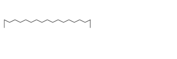
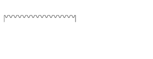
- wavy streaks are formed, but, for example, a triangular shape as shown in FIG. 2, a rectangular shape as shown in FIG. 3, and a trapezoidal shape as shown in FIG. Good things are mentioned.
- the shape of the streaks is not limited to these, and may be a shape such as a dimple shape obtained by sandblasting, sandpaper processing, peeling or the like.
- the streaks may be formed at a predetermined pitch or may be formed by changing the pitch. For example, the pitch in the vicinity of the center in the width direction may be made narrower or wider than the pitch at the ends in the width direction.
- the depth of the streaks is preferably 0.1 to 5000 ⁇ m. When the depth of the streaks is within the above range, the lubricating oil is likely to be retained on the sliding surface and excellent conformability is likely to be obtained.
- the depth of the streak is preferably 2000 ⁇ m or less, more preferably 1000 ⁇ m or less, further preferably 500 ⁇ m or less, and further preferably 100 ⁇ m or less for the reason of easy machining. It is more preferably 60 ⁇ m or less. Further, the depth of the streaks is preferably 0.5 ⁇ m or more, more preferably 1 ⁇ m or more, and further preferably 5 ⁇ m or more for the reason that the effect of the polymer monolith is exhibited.
- the sliding surface of the base material 1 is provided with streaks, but the surface roughness Ra is set to 0.5 to 1000 ⁇ m by texturing other than the streaks. May be.
- a polymer monolith 2 having a three-dimensional bicontinuous structure of continuous pores and a polymer skeleton is formed on the surface (sliding surface) of the base material 1 on the sliding side with respect to a mating member.
- the polymer monolith is a polymer porous body having pores that are three-dimensionally communicated with each other, and is formed by the continuous pores and the polymer skeleton without forming a three-dimensional co-continuous structure. That is.
- the maximum film thickness of the polymer monolith 2 is preferably 5000 ⁇ m or less, more preferably 2000 ⁇ m or less, further preferably 1000 ⁇ m or less, further preferably 500 ⁇ m or less, and 100 ⁇ m or less. Is even more preferable, and particularly preferably 50 ⁇ m or less.
- excellent conformability is easily obtained. That is, when the maximum film thickness of the polymer monolith 2 is the above, it is possible to suppress the compressive deformation of the polymer monolith 2 during the running-in process, and it is possible to reduce the friction coefficient.
- the porosity of the polymer monolith 2 is preferably 30% or more, more preferably 50% or more, further preferably 60% or more. When the porosity is 30% or more, the lubricating liquid can be retained more effectively.
- the upper limit of the porosity is preferably 90% or less, more preferably 85% or less, and further preferably 80% or less.
- the average pore diameter of the polymer monolith 2 is preferably 0.01 to 1000 ⁇ m.
- the average pore diameter of the polymer monolith 2 is preferably 10 ⁇ m or less, more preferably 5 ⁇ m or less, and further preferably 3 ⁇ m or less for the reason that an appropriate hardness can be easily obtained in a state containing a lubricating oil. It is preferably 2 ⁇ m or less, particularly preferably 2 ⁇ m or less.
- the average pore diameter of the polymer monolith 2 is preferably 0.05 ⁇ m or more, more preferably 0.1 ⁇ m or more, and further preferably 0.2 ⁇ m or more for the reason of easy production. ..
- the porosity and average pore diameter of the polymer monolith 2 are values measured by the mercury porosimetry method.
- the polymer monolith 2 can be formed by the method described below.
- the polymer skeleton of the polymer monolith is preferably a polymer of a polymerizable compound and a cross-linking agent, and is more preferably a polymer of a bifunctional or higher functional epoxy compound and a bifunctional or higher functional amine compound for ease of preparation. preferable.
- the polymerizable compound forming the polymer skeleton and the crosslinking agent will be described later.
- the polymer monolith 2 may contain silica particles. By forming a polymer monolith using a composition containing silica particles, dripping at the time of application can be suppressed.
- the silica particles will be described later.
- the polymer monolith 2 may further include cellulose nanofibers. According to this, the effect of increasing the mechanical strength of the polymer monolith can be expected.
- the polymer monolith 2 may further include an inorganic filler; a self-lubricating solid/nanomaterial such as graphite or fluorine particles.
- the polymer monolith 2 is formed so that the irregularities on the sliding side surface of the base material 1 are covered, and the sliding side surface of the base material 1 has the polymer monolith.
- the polymer monolith 2 is provided in at least a part of the concave portion of the surface of the base material 1 on the sliding side, and At least a part of the surface may be exposed from the polymer monolith 2.
- the coverage of the sliding side surface of the substrate with the polymer monolith is preferably 1% or more, and 10% or more. It is more preferable that it is 20% or more, still more preferably 30% or more, still more preferably 50% or more. When the coverage is in the above range, a more remarkable effect is likely to be obtained.
- the sliding member 10 having the configuration of FIG. 5 has a structure in which the polymer monolith 2 is embedded in each recess of the sliding side surface of the base material 1, but the polymer monolith 2 is formed in a part of the recess. It may not be formed, and the surface of the base material 1 may be exposed.
- each convex portion on the sliding side surface of the base material 1 is exposed from the polymer monolith 2, but a part of the convex portion is covered with the polymer monolith 2. May be.
- a protective film may be further formed on the surface of the polymer monolith 2.
- the thickness of the protective film is preferably 0.001 to 1 ⁇ m, more preferably 0.001 to 0.5 ⁇ m, further preferably 0.001 to 0.1 ⁇ m, and 0.001 to 0. Particularly preferably, it is 0.05 ⁇ m.
- the material of the protective film include aluminum, titanium, titanium nitride, titanium aluminum nitride, zirconium nitride, chromium, carbon and nitrogen carbide.
- Examples of the method for forming the protective film include a vapor deposition method and a sputtering method.
- the protective film is preferably a vapor deposition film or a sputtering film made of the above materials.
- the sliding member of the present invention can be used for various machine applications. Among them, it can be preferably used for the purpose of sliding with a mating member in a state where a strong load is applied to the sliding surface with the mating member. Examples of such applications include plain bearings. More specifically, sliding bearings for wheels of vehicles and the like can be mentioned.
- the method for producing a sliding member according to the present invention is a method in which a polymerizable compound and a cross-linking agent are formed on the sliding-side surface of a base material having a surface roughness Ra of 0.5-1000 ⁇ m on the sliding side with a mating member. And a pore-forming agent to form a coating film by coating a composition for forming a polymer monolith, the coating film is cured, and the pore-forming agent is removed from the cured film formed by curing to form a polymer monolith. It is characterized by doing.
- each step will be described.
- the polymer monolith-forming composition is applied to the surface on the sliding side of a substrate having a surface roughness Ra of 0.5 to 1000 ⁇ m on the surface sliding on the mating member to form a coating film.
- the base material may be subjected to treatment with a known coupling agent such as a silane coupling agent or plasma treatment in order to improve the affinity with the composition for forming a polymer monolith.
- the coating method of the composition for forming a polymer monolith is not particularly limited, and a known method can be used, for example, dip coating, spray coating, spin coating, bar coater coating, applicator coating, roll coater coating, curtain coater. Coating, screen printing and the like can be mentioned, and dip coating is preferable because it can be easily coated on an uneven surface or a curved surface. Details of the composition for forming a polymer monolith will be described later.
- the coating film of the polymer monolith-forming composition formed on the substrate is cured. That is, the polymerizable compound and the crosslinking agent are reacted to polymerize the polymerizable compound to cure the coating film (curing treatment). With the polymerization of the polymerizable compound, the polymer component increases, spinodal decomposition occurs, and a co-continuous structure can be expressed.
- the method of curing the coating film is not particularly limited, and can be appropriately selected depending on the types of the polymerizable compound and the crosslinking agent.
- a method of heating a method of irradiating electromagnetic waves such as ultraviolet rays and electron beams, and the like can be mentioned.
- the heating temperature is preferably 25 to 200° C., more preferably 30 to 180° C., and further preferably 40 to 160° C.
- the average pore diameter of the polymer monolith finally formed can be increased.
- the average pore diameter of the polymer monolith finally formed can be made smaller.
- the temperature is preferably 100 to 200° C., more preferably 120 to 180° C., and further preferably 150 to 180° C.
- the pore-forming agent is removed from the formed cured film. Specifically, the process of extracting the pore forming agent contained in the cured film is performed.
- the components described below are used as the pore-forming agent, since these are water-soluble, it is possible to put the pore-forming agent in a solvent having higher volatility than the pore-forming agent such as water, alcohol, and acetone.
- the pore-forming agent can be extracted from the cured film. Then, the displaced solvent is removed by volatilization to obtain a polymer monolith having a three-dimensional co-continuous structure of continuous pores and polymer skeleton.
- the pore-forming agent having a high boiling point can be volatilized and removed at a lower temperature by heating it under reduced pressure.
- a polymer monolith may be formed on the entire surface of the base material on the sliding side, and the polymer may be formed on at least a part of the recesses on the surface of the base material on the sliding side. While forming the monolith, at least a part of the surface of the base material on the sliding side may be exposed from the polymer monolith.
- the polymer monolith is formed in at least a part of the concave portion of the surface of the sliding side of the substrate, Moreover, it is possible to manufacture a sliding member having a structure in which at least a part of the sliding-side surface of the substrate is exposed from the polymer monolith.
- the composition for forming a polymer monolith contains a polymerizable compound, a crosslinking agent, and a pore forming agent.
- the polymerizable compound is not particularly limited as long as it is a compound capable of forming a polymer skeleton by polymerization with a crosslinking agent.
- a crosslinking agent for example, an epoxy compound, a (meth)acrylate compound, a styrene compound etc. are mentioned.
- epoxy compounds are preferable because they are excellent in flexibility and easily form a polymer monolith having a fine porous structure.
- epoxy compound examples include bisphenol A type epoxy resin, brominated bisphenol A type epoxy resin, bisphenol F type epoxy resin, bisphenol AD type epoxy resin, stilbene type epoxy resin, biphenyl type epoxy resin, bisphenol A novolac type epoxy resin, cresol novolac.
- diaminodiphenylmethane-type epoxy resin diaminodiphenylmethane-type epoxy resin, polyphenyl-based epoxy resin such as tetrakis(hydroxyphenyl)ethane base, fluorene-containing epoxy resin, 2,2,2-tri-(2,3-epoxypropyl)-
- a carbon atom derived from an aromatic ring such as triglycidyl isocyanurate such as isocyanate
- epoxy resin containing a heteroazine ring such as triazine ring-containing epoxy resin, N,N,N′,N′-tetraglycidyl-m-xylylenediamine, etc.
- Aromatic epoxy compounds including, aliphatic glycidyl ether type epoxy resin, aliphatic glycidyl ester type epoxy resin, alicyclic glycidyl ether type epoxy resin, alicyclic glycidyl ester type epoxy resin, 1,3-bis(N, Examples thereof include N'-diglycidylaminomethyl)cyclohexane and other aliphatic epoxy compounds containing no carbon atom derived from an aromatic ring. Among them, a compound having two or more glycidyl groups in the molecule, which is a bifunctional or more functional epoxy compound, is preferable. Preferred specific examples include 1,3-bis(N,N'-diglycidylaminomethyl)cyclohexane.
- cross-linking agent amine compounds, acid anhydrides, phenol compounds, hydrazide compounds and the like can be mentioned.
- amine compound examples include m-phenylenediamine, p-phenylenediamine, o-phenylenediamine, 4,4′-diaminodiphenyl sulfone, 4,4′-methylene-bis(2-chloroaniline), benzyldimethylamine and dimethylamino.
- Aromatic amine compounds such as methylbenzene; Aromatic amine compounds having heteroaromatic rings such as triazine rings; Ethylenediamine, diethylenetriamine, triethylenetetramine, tetraethylenepentamine, iminobispropylamine, bis(hexamethylene)triamine, 1, 3,6-Trisaminomethylhexane, polymethylenediamine, trimethylhexamethylenediamine, polyetherdiamine, isophoronediamine, menthanediamine, N-aminoethylpiperazine, 3,9-bis(3-aminopropyl) 2,4,8 , 10-Tetraoxaspiro(5,5)undecane adduct, alicyclic amine compounds such as bis(4-aminocyclohexyl)methane and modified products thereof; 1,6-hexamethylenebis(N,N-dimethyl) Aliphatic polyamine hydrazide compounds such as semicarbazide); alipha
- acid anhydrides examples include aromatic acid anhydrides such as phthalic anhydride, trimetic anhydride, and pyrometic anhydride.
- phenolic compounds include novolac type phenolic resins.
- hydrazide compound examples include aromatic hydrazide compounds such as isophthalic acid dihydrazide; aliphatic hydrazide compounds such as adipic acid dihydrazide, sebacic acid dihydrazide, and dodecanedioic acid dihydrazide.
- the crosslinking agent is preferably an amine compound, and more preferably a compound having two or more amino groups in the molecule, which is a bifunctional or higher functional amine compound.
- the bifunctional or higher amine compound is preferably an alicyclic amine compound.
- a preferred specific example is bis(4-aminocyclohexyl)methane.
- the polymerizable compound is a bifunctional or higher epoxy compound (preferably a bifunctional or higher aliphatic epoxy compound), and the crosslinking agent is a bifunctional or higher amine compound (preferably a bifunctional or higher alicyclic amine compound).
- the crosslinking agent is a bifunctional or higher amine compound (preferably a bifunctional or higher alicyclic amine compound).
- the blending ratio of the polymerizable compound and the crosslinking agent in the composition for forming a polymer monolith may be determined in consideration of the crosslinking density and the like.
- the amine equivalent of the crosslinking agent is 0.6 to 1 equivalent to 1 equivalent of the epoxy group of the polymerizable compound. It is preferable to adjust it so that it falls within the range of 1.5.
- the pore-forming agent is present in the polymerization reaction system that forms the polymer skeleton during polymerization, and is removed from the cured film to form a three-dimensional co-continuous structure of continuous pores and the polymer skeleton. It is an ingredient.
- the pore-forming agent is preferably a compound capable of dissolving the polymerizable compound and the crosslinking agent and capable of causing reaction-induced phase separation after the polymerizable compound and the crosslinking agent are polymerized.
- the pore-forming agent examples include cellosolves such as methyl cellosolve and ethyl cellosolve, esters such as ethylene glycol monomethyl ether acetate and propylene glycol monomethyl ether acetate, glycols such as polyethylene glycol, polypropylene glycol, triethylene glycol and diethylene glycol.
- cellosolves such as methyl cellosolve and ethyl cellosolve
- esters such as ethylene glycol monomethyl ether acetate and propylene glycol monomethyl ether acetate
- glycols such as polyethylene glycol, polypropylene glycol, triethylene glycol and diethylene glycol.
- polyethylene glycol, polypropylene glycol, triethylene glycol and diethylene glycol are preferable.
- the molecular weight of polyethylene glycol and polypropylene glycol is preferably less than 600, but those having a molecular weight of more than 600 can also be used.
- a hole-forming agent that has a good compatibility with the lubricating oil used for the sliding member.
- a pore-forming agent it can be used as a component even when the polymer monolith contains the pore-forming agent, and the steps such as washing and removing the pore-forming agent can be simplified or omitted. Therefore, the manufacturing cost of the sliding member can be further reduced.
- the compounding amount of the pore forming agent in the composition for forming a polymer monolith is preferably 50 to 700 parts by mass, and preferably 200 to 500 parts by mass, based on 100 parts by mass of the total of the polymerizable compound and the crosslinking agent. Is more preferable.
- the amount of the pore-forming agent is within the above range, it is easy to manufacture a sliding member having excellent conformability.
- the polymer monolith-forming composition may further contain a surfactant.
- a surfactant By including a surfactant in the composition for forming a polymer monolith, it is easy to control the phase separation size after polymerization.
- the surfactant is not particularly limited, and includes an anionic surfactant, a cationic surfactant, a nonionic surfactant, a block copolymer composed of a hydrophilic block and a hydrophobic block, for example, a polyacrylic acid block and a polyacrylic ester block. Examples thereof include block copolymers, block copolymers composed of polyoxyethylene blocks and polyacrylic ester blocks, block copolymers composed of polyoxyethylene blocks and polyoxypropylene blocks, and the like.
- the molecular weight of the surfactant is also not particularly limited, and low molecular weight compounds and high molecular weight compounds can be used.
- anionic surfactants include fatty acid salts, sulfuric acid ester salts of higher alcohols, phosphoric acid ester salts of fatty alcohols, alkylallyl sulfonates, formalin condensed naphthalene sulfonates and the like.
- cationic surfactants include alkyl primary amine salts, alkyl secondary amine salts, alkyl tertiary amine salts, alkyl quaternary ammonium salts, and pyridinium salts.
- nonionic surfactants include polyoxyethylene alkyl ethers, polyoxyethylene alkylphenyl ethers, polyoxyethylene alkyl esters, sorbitan alkyl esters, polyoxyethylene sorbitan alkyl esters, and the like.
- examples of the polymer surfactant include partially saponified polyvinyl alcohol, starch, methyl cellulose, carboxymethyl cellulose, hydroxyethyl cellulose and partially saponified polymethacrylate.
- the content of the surfactant in the composition for forming a polymer monolith is preferably 0.01 to 10 parts by mass, and 0.1 to 10 parts by mass with respect to 100 parts by mass as the total of the polymerizable compound and the crosslinking agent. More preferably, it is a part.
- the blending amount of the surfactant is within the above range, it is easy to manufacture a sliding member having excellent conformability.
- the composition for forming a polymer monolith may further contain silica particles.
- silica particles By including silica particles in the polymer monolith-forming composition, the viscosity of the polymer monolith-forming composition can be appropriately increased, and dripping at the time of application can be suppressed.
- the average particle diameter of the silica particles is preferably 0.001 to 100 ⁇ m, more preferably 0.01 to 10 ⁇ m, and further preferably 0.01 to 0.1 ⁇ m.
- the average particle size of the silica particles is within the above range, the viscosity of the polymer monolith-forming composition can be appropriately increased, and it is easy to suppress dripping during coating.
- silica particles examples include “Aerosil” (Japan Aerosil Co., Ltd.) and “Reorosil” (Tokuyama Co., Ltd.).
- the amount of the silica particles to be blended is preferably 0.001 to 20 parts by mass, more preferably 1 to 10 parts by mass, based on 100 parts by mass of the total amount of the polymerizable compound, the cross-linking agent and the pore-forming agent. ..
- the blending amount of the silica particles is within the above range, the viscosity of the polymer monolith-forming composition can be appropriately increased, and it is easy to suppress dripping during coating.
- the polymer monolith-forming composition may be blended with a low boiling point solvent having a boiling point of 100° C. or lower.
- the boiling point of the low boiling point solvent is preferably 90°C or lower, more preferably 80°C or lower, and further preferably 60°C or lower.
- the solvent is easily removed from the coating film quickly, and dripping during coating is easily suppressed.
- Acetone, tetrahydrofuran, ethanol, etc. are mentioned as a preferable low boiling point solvent, and acetone is especially preferable.
- the low boiling point solvent When the low boiling point solvent is added to the composition for forming a polymer monolith, the low boiling point solvent should be added in an amount of 1 to 1000 parts by mass based on 100 parts by mass of the total of the polymerizable compound, the cross-linking agent and the pore forming agent. Is preferred and 1 to 100 parts by mass is more preferred. When the blending amount of the low boiling point solvent is in the above range, it is easy to suppress dripping during coating.
- Cellulose nanofibers may be added to the composition for forming a polymer monolith for the purpose of improving its mechanical properties.
- the type of cellulose that can be used as a raw material for the cellulose nanofibers is not particularly limited, and for example, in addition to wood-based natural cellulose, non-wood such as cotton linter, bamboo, hemp, bagasse, kenaf, bacterial cellulose, sea squirt cellulose, and baronia cellulose. Natural cellulose and regenerated cellulose typified by rayon fiber and cupra fiber can be used.
- the method for producing cellulose nanofibers is also not particularly limited, and for example, in addition to mechanical treatment with a grinder, oxidation treatment using an N-oxyl compound such as TEMPO, dilute acid hydrolysis treatment, enzyme treatment, etc. is used in combination with mechanical treatment to produce cellulose.
- Methods for obtaining nanofibers are known.
- Bacterial cellulose can also be used as cellulose nanofibers.
- regenerated cellulose nanofibers obtained by dissolving various natural celluloses in various cellulose solvents and then electrospinning may be used.
- the amount of cellulose nanofibers is 0.01 to 1000 parts by mass with respect to 100 parts by mass of the total of the polymerizable compound, the cross-linking agent, and the pore-forming agent. It is preferable that the amount is 1 to 100 parts by mass.
- the blending amount of the cellulose nanofibers is within the above range, the mechanical properties of the polymer monolith are improved.
- the composition for forming a polymer monolith is a leveling agent, an antifoaming agent, a colorant, an inorganic filler, various additives such as self-lubricating solids/nanomaterials such as graphite and fluorine particles, for the purpose of improving various properties. Can be added. Care should be taken to select those that do not interfere with spinodal degradation to produce the monolith structure.
- the viscosity of the composition for forming a polymer monolith at 25° C. is preferably 10 mPa ⁇ s or more, and more preferably 100 mPa ⁇ s or more. When the viscosity is within the above range, it is easy to suppress dripping during coating.
- the sliding system of the present invention includes a sliding bearing made of the above-described sliding member of the present invention, a rotating shaft provided on the inner peripheral surface side of the sliding bearing, and a lubricating oil interposed between the sliding shaft and the rotating shaft.
- FIG. 6 is a diagram showing an embodiment of a sliding system
- FIG. 7 is a sectional view taken along the line AA of the sliding bearing of FIG.
- Reference numeral 50 is a bearing system.
- Reference numeral 11 in FIG. 6 is a sliding bearing made of the above-described sliding member of the present invention. That is, a polymer having a three-dimensional bicontinuous structure of continuous pores and a polymer skeleton on the sliding surface of the base material 1 having a surface roughness Ra of 0.5 to 1000 ⁇ m on the sliding surface with the mating member.
- the monolith 2 is formed.
- a rotary shaft 31 is provided on the inner peripheral surface side of the slide bearing 11.
- the arrow direction indicates the rotation direction of the rotary shaft 31.
- the polymer monolith described above may be formed on the surface of the rotary shaft 31 on the slide bearing 11 side. As a result, the polymer monolith can be rapidly supplied to the metal surface exposed on the rotary shaft side surface of the slide bearing 11, so that excellent conformability can be rapidly realized particularly immediately after the start of sliding.
- the lubricating oil 21 is interposed between the sliding shaft and the rotating shaft.
- the type of lubricating oil is not particularly limited, and known lubricating oil can be used.
- mineral oil such as paraffinic mineral oil and naphthenic mineral oil
- hydrocarbon oil such as polybutene, poly( ⁇ -olefin), alkylbenzene, and alkylnaphthalene
- natural oil and fat polyol ester oil; phosphate ester oil; diester oil; polyglycol Oils
- silicone oils polyphenyl ether oils; alkyl diphenyl ether oils; fluorinated oils; ionic liquids and the like.
- These lubricating oils may be used alone or in combination of two or more.
- additives can be added to the lubricating oil, if necessary.
- the additives include conductivity imparting agents such as carbon black, extreme pressure agents such as organic zinc compounds and organic molybdenum compounds, antioxidants such as amine-based compounds, phenol-based compounds and sulfur-based compounds, sulfur-based compounds and phosphorus-based compounds.
- wear inhibitors such as, rust preventives such as polyhydric alcohol esters, viscosity index adjusters such as polymethacrylate and polystyrene, solid lubricants such as molybdenum disulfide and graphite, and oiliness agents such as esters and alcohols.
- the sliding system of the present invention includes a wheel drive system unit of a vehicle or the like, a shaft drive system of an electric motor, and the like.
- composition for forming polymer monolith As the polymerizable compound, 10 parts by mass of an epoxy compound represented by the following formula (1) having an epoxy equivalent of 95 to 110 (average 102) (trade name “Tetrad C”, Mitsubishi Gas Chemical Industry Co., Ltd.), as a crosslinking agent 5.75 parts by mass of bis(4-aminocyclohexyl)methane represented by the following formula (2) having an amine value of 520 to 550 (manufactured by Tokyo Kasei Kogyo Co., Ltd.), and an average molecular weight of 200 as a pore forming agent.
- composition for polymer monolith formation was obtained by mixing with "Awatori Kentaro" of a revolution mixer.
- Example 1 A composition for forming a polymer monolith is applied by dipping onto the surface of an aluminum alloy having a surface roughness Ra of 2.776 ⁇ m and a thickness of 330 ⁇ m, in which wavy streaks having a depth of 12 ⁇ m are formed at a pitch of 300 ⁇ m, and then at 60° C. at 110° C. A heating treatment was performed by heating for 1 minute, and then an annealing treatment was performed at 180° C. for 30 minutes to form a cured film.
- a polymer monolith having a three-dimensional co-continuous structure of continuous pores and a polymer skeleton is obtained by removing the pore-forming agent from the cured film by washing with methanol, removing the surface with abrasive paper while immersing in water, and washing with water. Then, the sliding member of Example 1 was manufactured.
- the maximum film thickness of the obtained polymer monolith was 12 ⁇ m, the porosity was 72%, and the average pore diameter was 1 ⁇ m.
- Comparative Example 1 An aluminum alloy (surface roughness Ra: 2.776 ⁇ m, thickness: 330 ⁇ m) in which wavy scratches having a depth of 12 ⁇ m were formed at a pitch of 300 ⁇ m was used as a sliding member of Comparative Example 1.
- composition for forming a polymer monolith is applied by dip coating to the surface of an aluminum alloy having a surface roughness Ra of 0.082 ⁇ m and a thickness of 330 ⁇ m, followed by heating at 110° C. for 60 minutes for curing treatment, and then annealing at 180° C. for 30 minutes. Treatment was performed to form a cured film. Then, the pore-forming agent was removed from the cured film by a method of washing with methanol to form a polymer monolith having a three-dimensional co-continuous structure of continuous pores and a polymer skeleton to produce a sliding member of Comparative Example 2.
- the maximum film thickness of the obtained polymer monolith was 10 ⁇ m, the porosity was 72%, and the average pore diameter was 1 ⁇ m.
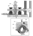
- Example 1 A sliding test was performed on the sliding members of Example 1, Comparative Example 1 and Comparative Example 2 using the test apparatus shown in FIG.
- reference numeral 101 is an acoustic emission sensor
- reference numeral 102 is a thermocoupler
- reference numeral 103 is a bearing test piece
- reference numeral 104 is a ring test piece
- reference numeral 201 is a torque meter
- reference numeral 202 is An oil bath
- a reference numeral 203 is a shaft
- a reference numeral 204 is a swing part
- a reference numeral 205 is a particle counter.
- the bearing test piece 103 the sliding members of Example 1, Comparative Example 1 and Comparative Example 2 were used.
- Lubricating oil at 58 to 62°C from the direction of the arrow of the oil inlet (mineral oil as a base oil, lubricating oil containing a viscosity index improver as an additive, kinematic viscosity at 60°C 10.37 mm 2 /s) was supplied at a flow rate of 5 mL/s, and the bearing test piece 103 was slid from above with a load (Load) of 100 N against the ring test piece 104 rotating at a sliding speed of 2.0 m/s. When the slip distance reached 2000 m, the load was increased to 500 N and sliding was performed. Next, when the sliding distance reached 2500 m, the load was increased to 1000 N and sliding was performed.
- Load load
- FIG. 9 to 11 are diagrams showing changes in friction coefficient and temperature of the bearing test piece.
- 9 is a test result of a bearing test piece using the sliding member of Example 1
- FIG. 10 is a test result of a bearing test piece using the sliding member of Comparative Example 1
- FIG. 11 is a comparative example 2.
- 3 is a test result of a bearing test piece using the sliding member of FIG. 9 to 11, the chart (1) is a chart of friction coefficient, and the chart (2) is a chart of temperature of the bearing test piece.
- FIG. 12 shows the Stribeck curves of the bearing test pieces of Example 1, Comparative Example 1 and Comparative Example 2.
- 13 to 15 show the sliding surface of the bearing test piece after the sliding test.
- 13 is a sliding surface of a bearing test piece using the sliding member of Example 1
- FIG. 14 is a sliding surface of a bearing test piece using the sliding member of Comparative Example 1
- FIG. 7 is a sliding surface of a bearing test piece using the sliding member of Example 2.
- Example 1 Under a constant load with a slip distance of 0 to 2000 m (load 100 N), the friction coefficient gradually decreased, and the temperature of the bearing test piece was stable at around 50° C. It was When the sliding distance was 2000 to 4000 m, the load was increased stepwise for sliding, but there was no abrupt change in the friction coefficient or temperature, and the behavior was more stable than in Comparative Examples 1 and 2. When the sliding distance was 4000 to 5000 m, the sliding of the lubricating oil was stopped and the friction coefficient and the temperature did not change rapidly. Further, as shown in FIG. 13, a good familiar surface was formed. When the sliding surface was observed using a scanning electron microscope, the sliding member of Example 1 had some places where the polymer monolith remained in the recesses on the surface of the aluminum alloy after the test.
- Comparative Example 1 the friction coefficient was larger than that in Example 1 under a constant load (load 100 N) with a slip distance of 0 to 2000 m. In addition, a large amount of abrasion powder was generated. The abrasion powder was measured with a particle counter 205. When the sliding distance was 2000 to 4000 m, the load was increased stepwise for sliding, but a sharp change in the friction coefficient and temperature was observed. In addition, a large amount of abrasion powder was generated. Further, in the sliding member of Comparative Example 1, the projections on the surface of the aluminum alloy were worn and a smooth surface was formed, but there was a portion where wear powder was buried.
- Comparative Example 2 the coefficient of friction and the temperature were stable under a constant load (load 100 N) with a slip distance of 0 to 2000 m. However, when the sliding distance was 2000 to 4000 m and sliding was performed while gradually increasing the load, a sharp change in the friction coefficient was observed. The temperature increased continuously with the increase of slip distance. Further, when the sliding distance was 4000 to 5000 m, the sliding of the lubricating oil was stopped, but the temperature rose, and seizure occurred at the sliding distance of 4500 m. Further, as shown in FIG. 15, in the sliding member of Comparative Example 2, there was a portion where the polymer monolith was peeled off. Furthermore, there were some areas where seizure occurred and the material was deformed.
- Test Example 2 A sliding speed change test of the sliding members of Example 1 and Comparative Example 1 was conducted using the test device shown in FIG. The description of the reference numerals in FIG. 8 is as described above. As the bearing test piece 103, the sliding members of Example 1 and Comparative Example 1 were used.
- Lubricating oil at 58 to 62°C from the direction of the arrow of the oil inlet (mineral oil as a base oil, lubricating oil containing a viscosity index improver as an additive, kinematic viscosity at 60°C 10.37 mm 2 /s) was supplied at a flow rate of 5 mL/s, and the bearing test piece 103 was slid from above with a load (Load) of 100 N against the ring test piece 104 rotating at a sliding speed of 6.0 m/s. When the slip distance reached 2000 m, the load was increased to 500 N and sliding was performed.
- Load load
- the slip speed of the ring test piece 104 was reduced to 5.5 m/s while maintaining the load (Load) at 500 N. Then, the sliding speed of the ring test piece 104 was reduced by 0.5 m/s at every sliding distance of 500 m. The test was terminated when the slip distance reached 8000 m.
- FIG. 16 shows a diagram showing changes in friction coefficient and temperature of the bearing test piece.
- the chart of (1-1) is a chart of the coefficient of friction of Example 1
- the chart of (1-2) is a chart of the temperature of the bearing test piece of Example 1
- (2-1) is a chart of the coefficient of friction of Comparative Example 1
- the chart (2-2) is a chart of the temperature of the bearing test piece of Comparative Example 1.
- FIG. 17 shows the Stribeck curves of the bearing test pieces of Example 1 and Comparative Example 1.
- Example 1 at the time when the load was increased to 500 N (at a sliding distance of 2000 m), a sharp increase in the friction coefficient was not seen. Further, the temperature rise was suppressed more than in Comparative Example 1. Moreover, even if the sliding speed was reduced, there was almost no change in the friction coefficient, indicating stable behavior. Further, from FIG. 17, there is a correlation between the friction coefficient and the number of bearing characteristics, and the friction coefficient showed the minimum value when the number of bearing characteristics was 5.33 ⁇ 10 ⁇ 9 .
- Example 11 A disc-shaped base material having a diameter of 30 mm and a thickness of 2 mm made of a polyamide resin (MC900NC) was formed on the surface of a disc-shaped substrate having a depth of 50 ⁇ m by using a laser beam machine (PRT-HAJIMCL1 manufactured by AULASER CORPORATION). The marks were formed at a pitch of 300 ⁇ m, and the surface roughness Ra was adjusted to 22 ⁇ m. Next, the composition for forming a polymer monolith is dip-coated on the surface of this base material, followed by heating at 110° C. for 60 minutes to perform a curing treatment, and then annealing treatment at 180° C.
- MC900NC polyamide resin
- a polymer monolith having a three-dimensional bicontinuous structure of continuous pores and polymer skeleton by removing the pore-forming agent from the cured film by washing with methanol, removing the surface with abrasive paper while soaking in water, and washing with water. was formed to produce the sliding member of Example 11.
- the maximum film thickness of the obtained polymer monolith was 50 ⁇ m, the porosity was 72%, and the average pore diameter was 1 ⁇ m.
- Example 12 An aluminum vapor deposition film having a thickness of 15 nm was formed on the surface of the sliding member obtained by the method of Example 11 using a vacuum vapor deposition machine (manufactured by Osaka Vacuum Co., Ltd.) to produce the sliding member of Example 12. did.
- the surface roughness Ra after vapor deposition of aluminum was 22 ⁇ m.
- the maximum film thickness of the polymer monolith was 50 ⁇ m, the porosity was 72%, and the average pore diameter was 1 ⁇ m.
- Comparative Example 11 A disc-shaped base material having a diameter of 30 mm and a thickness of 2 mm made of a polyamide resin (MC900NC) was formed on the surface of a disc-shaped substrate having a depth of 50 ⁇ m by using a laser beam machine (PRT-HAJIMCL1 manufactured by AULASER CORPORATION). The marks were formed at a pitch of 300 ⁇ m, and the surface roughness Ra was adjusted to 22 ⁇ m. This base material was used as the sliding member of Comparative Example 11.
- FIG. 18 shows the Stribeck curves of Example 11, Example 12 and Comparative Example 11.
- the friction coefficient of Comparative Example 11 is almost constant regardless of the Stribeck characteristic number (horizontal axis, viscosity ⁇ sliding speed/load)
- boundary lubrication is achieved even at high speeds. That is, it is determined that the two surfaces are in contact with each other. For this reason, no significant effect was observed in the initial friction test, but there is concern about the progress of wear in the long-term friction test.
- Examples 11 and 12 since the friction coefficient depends on the Stribeck characteristic number, mixed lubrication was determined, and it is considered that contact between the two surfaces was suppressed. Therefore, it is considered that the progress of wear can be suppressed in the long-term friction test.
- Base material 2 Polymer monolith 10: Sliding member 11: Bearing 21: Lubricating oil 31: Rotating shaft 50: Bearing system 101: Acoustic emission sensor 102: Thermocoupler 103: Bearing test piece 104: Ring test piece 201: Torque Meter 202: Oil bath 203: Shaft 204: Swing parts 205: Particle counter
Landscapes
- Engineering & Computer Science (AREA)
- General Engineering & Computer Science (AREA)
- Chemical & Material Sciences (AREA)
- Mechanical Engineering (AREA)
- Organic Chemistry (AREA)
- Chemical Kinetics & Catalysis (AREA)
- Materials Engineering (AREA)
- Metallurgy (AREA)
- Health & Medical Sciences (AREA)
- Medicinal Chemistry (AREA)
- Polymers & Plastics (AREA)
- Sliding-Contact Bearings (AREA)
- Compositions Of Macromolecular Compounds (AREA)
- Manufacture Of Porous Articles, And Recovery And Treatment Of Waste Products (AREA)
Abstract
なじみ性に優れた摺動部材、摺動部材の製造方法および摺動システムを提供する。相手部材との摺動側の表面の表面粗さRaが0.5~1000μmである金属基材1の前記摺動側の表面にポリマーモノリス2が形成された摺動部材10。
Description
本発明は、摺動部材、摺動部材の製造方法および摺動システムに関する。
すべり軸受などの摺動部材においては、特許文献1に記載されているように、母体となる基材の相手部材との摺動側の表面に、条痕加工などのテクスチャリングを施して用いることがある。
一方で、近年では、ポリマーモノリスに関する研究が進められている。
例えば、特許文献2には、硬化性樹脂と硬化剤とポロゲンと増粘剤とを含む硬化性組成物を基材上に塗布し、前記塗布により形成された塗布物を硬化し、前記硬化により形成された硬化塗膜内のポロゲンを除去することにより、多孔質モノリスコーティング膜を基材の表面に保持する、多孔質モノリスコーティング構造物の製造方法に関する発明が記載されている。特許文献2に関する発明によれば、表面に非多孔性のスキン層が形成されていない多孔質モノリスコーティング構造物を、研磨等の工程を経ることなく、基材上に成膜することができることが記載されている。
一般的に、すべり軸受などの摺動部材は、相手部材とのなじみ処理を経て用いられている。ここで、なじみ処理とは、あらかじめ摺動部材と相手部材とを摺動させておくことにより、両者の摺動面を均一化させていく処理のことである。
しかしながら、従来より知られているすべり軸受などの摺動部材では、相手部材との摩擦係数が大きい傾向にあった。このため、良好ななじみ面を得るのに時間を要することがあった。また、なじみ処理中に摩耗粉の発生量が多い傾向にあり、良好ななじみ面が得られにくい傾向にあった。また、なじみ処理中に摺動部材の温度が突発的に上昇して焼付きが生じることもあった。例えば、相手部材との摺動面に強い荷重が印加された状態で相手部材と摺動させた場合において、摺動部材の温度が上昇して焼付きが生じやすかった。
また、一般的に、なじみ処理は、摺動部材と相手部材との間に潤滑油を介在させた状態で行うことが多いが、潤滑油の供給が少ない貧潤滑条件下でもなじみ処理を行うこともある。このような貧潤滑条件下では、なじみ処理中に摺動部材と相手部材とが直接接しやすく、摺動部材の温度が急激に上昇して焼付きが生じ易かった。
このように、従来より知られているすべり軸受などの摺動部材は、なじみ性について更なる改善の余地があった。
なお、特許文献2には、多孔質モノリスコーティング構造物に関する発明が記載されているが、摺動部材に関する記載はない。
よって、本発明の目的は、なじみ性に優れた摺動部材、摺動部材の製造方法および摺動システムを提供することにある。
本発明者らが鋭意検討を行った結果、表面粗さがある程度高い基材の表面にポリマーモノリスを形成することにより、優れたなじみ性が得られることを見出し、本発明を完成するに至った。よって、本発明は以下を提供する。
<1> 相手部材との摺動側の表面の表面粗さRaが0.5~1000μmである基材の上記摺動側の表面にポリマーモノリスが形成された摺動部材。
<2> 上記ポリマーモノリスは潤滑油を含む、<1>に記載の摺動部材。
<3> 上記ポリマーモノリスのポリマー骨格は、2官能以上のエポキシ化合物と2官能以上のアミン化合物の重合物である、<1>または<2>に記載の摺動部材。
<4> 上記ポリマーモノリスの空孔率が30%以上である、<1>~<3>のいずれか1つに記載の摺動部材。
<5> 上記ポリマーモノリスの平均空孔径が0.01~100μmである、<1>~<4>のいずれか1つに記載の摺動部材。
<6> 上記ポリマーモノリスは、更にシリカ粒子を含む、<1>~<5>のいずれか1つに記載の摺動部材。
<7> 上記基材は金属基材である、<1>~<6>のいずれか1つに記載の摺動部材。
<8> 上記基材の上記摺動側の表面には凹凸が形成されて表面粗さRaが0.5~1000μmとされており、
上記基材の上記摺動側の表面の凹部の少なくとも一部に上記ポリマーモノリスを有している、<1>~<7>のいずれか1つに記載の摺動部材。
<9> 上記基材の上記摺動側の表面の凹部の少なくとも一部に上記ポリマーモノリスを有し、かつ、上記基材の上記摺動側の表面の少なくとも一部が上記ポリマーモノリスから露出している、<8>に記載の摺動部材。
<10> 上記基材の上記摺動側の表面には、条痕が形成されている、<1>~<9>のいずれか1つに記載の摺動部材。
<11> 上記ポリマーモノリスの最大膜厚が2000μm以下である、<1>~<10>のいずれか1つに記載の摺動部材。
<12> 上記摺動部材はすべり軸受である、<1>~<11>のいずれか1つに記載の摺動部材。
<13> 相手部材との摺動側の表面の表面粗さRaが0.5~1000μmである基材の上記摺動側の表面に、重合性化合物と架橋剤と孔形成剤とを含むポリマーモノリス形成用組成物を塗布して塗布膜を形成し、上記塗布膜を硬化し、硬化により形成された硬化膜から上記孔形成剤を除去してポリマーモノリスを形成する、摺動部材の製造方法。
<14> 上記基材の上記摺動側の表面には凹凸が形成されて表面粗さRaが0.5~1000μmとされており、
上記基材の上記摺動側の表面の凹部の少なくとも一部に上記ポリマーモノリスを形成する、<13>に記載の摺動部材の製造方法。
<15> 上記基材の上記摺動側の表面の凹部の少なくとも一部に上記ポリマーモノリスを形成するとともに、上記基材の上記摺動側の表面の少なくとも一部を上記ポリマーモノリスから露出させる、<13>に記載の摺動部材の製造方法。
<16> 上記重合性化合物は2官能以上のエポキシ化合物であり、上記架橋剤は2官能以上のアミン化合物である、<13>~<15>のいずれか1つに記載の摺動部材の製造方法。
<17> 上記ポリマーモノリス形成用組成物は、更にシリカ粒子を含む、<13>~<16>のいずれか1つに記載の摺動部材の製造方法。
<18> 上記ポリマーモノリス形成用組成物は、更に沸点が100℃以下の有機溶剤を含む、<13>~<17>のいずれか1つに記載の摺動部材の製造方法。
<19> すべり軸受と、
上記すべり軸受けの内周面側に設けられた回転軸と、
上記すべり軸と上記回転軸との間に介在する潤滑油と、を備えた摺動システムであって、
上記すべり軸受が、<1>~<12>のいずれか1つに記載の摺動部材である、摺動システム。
本発明は、なじみ性に優れた摺動部材、摺動部材の製造方法および摺動システムを提供することができる。
本明細書において「~」という記号を用いて表される数値範囲は、「~」の前後に記載される数値をそれぞれ下限値および上限値として含む範囲を意味する。
本明細書において、「(メタ)アクリレート」は、「アクリレート」および「メタクリレート」の両方、または、いずれかを意味し、「(メタ)アクリル」は、「アクリル」および「メタクリル」の両方、または、いずれかを意味する。
<摺動部材>
本発明の摺動部材は、相手部材との摺動側の表面の表面粗さRaが0.5~1000μmである基材の前記摺動側の表面にポリマーモノリスが形成された摺動部材であることを特徴とする。
本発明の摺動部材は、相手部材との摺動側の表面の表面粗さRaが0.5~1000μmである基材の前記摺動側の表面にポリマーモノリスが形成された摺動部材であることを特徴とする。
本発明の摺動部材は、なじみ処理中における摺動部材の温度の突発的な上昇を抑制して焼付きの発生を抑制できる。また、なじみ処理中に荷重やすべり速度(摺動速度)が変動しても、摩擦係数の急激な上昇を抑制でき、なじみ処理を安定的に行うことができる。このように、本発明の摺動部材は、なじみ性に優れ、焼付きなどがなく、良好ななじみ面を短時間で形成することができる。このような効果が得られる理由としては、以下によるものと推測される。
本発明の摺動部材は、基材の表面にポリマーモノリスを有しているが、ポリマーモノリスは、連続空孔とポリマー骨格の3次元共連続構造を有しているので、柔軟性が高く、内部に潤滑油を効率よく保持しやすい。このようなポリマーモノリスが、摺動側の表面の表面粗さRaが0.5~1000μmである基材の摺動側の表面に形成されていることにより、なじみ処理時における相手部材との摩擦係数を低く抑えることができる。また、なじみ処理時に相手部材との摺動面に強い荷重が印加されても、摺動部材の温度の突発的な上昇を抑制することもでき、焼付きの発生を抑制することができる。また、摩擦係数の急激な変動なども抑制できる。
また、なじみ処理が徐々に進むと、基材の摺動側の表面(以下、摺動面ともいう)の凸部が摩耗されて摺動面が徐々に平坦化されるとともに、ポリマーモノリスも徐々に摩耗されていくが、なじみ処理がある程度進んだ段階でも摺動面の凹部にポリマーモノリスが残存した状態でなじみ処理が進行すると推測される。このため、なじみ処理がある程度進行した段階でも、ポリマーモノリスによる優れた摩擦特性の改善効果や焼付き抑制効果を持続させることができると推測される。そのため、例えば、なじみ処理がある程度進んだ段階で、相手部材との摺動面に強い荷重が印加されたり、すべり速度(摺動速度)が変動しても、摩擦係数の急激な変動や、摺動部材の温度の突発的な上昇を抑制できる。
このような理由により、本発明の摺動部材は、優れたなじみ性を有していると推測される。
また、ポリマーモノリスは柔軟性に優れた構造を有しているので、なじみ処理時に強い衝撃が加わっても、焼付けなどの発生を抑制できる。このため、本発明の摺動部材は耐衝撃性にも優れる。
また、なじみ処理後も基材の摺動面の凹部にポリマーモノリスが残存している場合もあり、この場合は、ポリマーモノリスによって優れた潤滑特性や優れた耐衝撃性を得ることができる。
また、従来は、基材の摺動面に条痕加工などのテクスチャリングを施す場合、高度に研磨加工を行っていたが、本発明の摺動部材によれば、ポリマーモノリスを形成することにより、高度研磨を施さなくても(例えば、一次機械加工のみなど)優れたなじみ性を得ることができ、摺動部材の製造コストを低減することもできる。なお、本発明の摺動部材において、基材の摺動面に対して高度に研磨加工が施されたものを用いてもよいことは言うまでもない。
また、本発明の摺動部材によれば、潤滑油の供給が少ない貧潤滑条件下でなじみ処理を行った場合であっても、摺動部材の温度の突発的な上昇や摩擦係数の急激な変動を抑制することができる。このような効果が得られる理由としては、ポリマーモノリスが内部に潤滑油を効果的に保持しやすいためであると推測される。
また、本発明の摺動部材によれば、起動と停止を繰り返して行うような間欠運転にてなじみ処理を行った場合であっても、摺動部材の温度の突発的な上昇や摩擦係数の急激な変動を抑制することができ、良好ななじみ面を形成することができる。このような効果が得られる理由としては、上述したように、ポリマーモノリスが内部に潤滑油を効果的に保持しやすいことから、潤滑油を内部に保持したポリマーモノリスの効果により、装置の駆動停止時のオイル切れによる焼き付き等を問題を回避することができるためであると推測される。
本発明の摺動部材について、図面を用いて詳細に説明する。図1は、摺動部材の一実施形態を示す図である。符号1は基材であり、符号2はポリマーモノリスであり、符号10は摺動部材である。
基材1の材質としては、特に限定されない。例えば、金属、樹脂、無機材料などが挙げられる。金属としては、鉄、アルミニウム、銅及びこれらの金属原子を含む合金などが挙げられる。樹脂としては、ポリアセタール樹脂、ポリアミド樹脂、ポリイミド樹脂、ポリカーボネート樹脂、ポリサルフォン樹脂、ポリエーテルサルフォン樹脂、フッ素樹脂などが挙げられる。無機材料としては、炭化ケイ素、酸化アルミニウムなどが挙げられる。基材1は、単層構造体であってもよく、積層構造体であってもよい。なかでも、より優れたなじみ性が得られ、本発明の効果がより顕著に得られやすいという理由から基材1の材質は金属であることが好ましい。すなわち、基材1は金属基材であることが好ましい。また、金属の種類としては、硬さ・じん性・耐磨耗性・耐衝撃性に優れるという理由からはだ焼き鋼(例えばSCM420など)や高炭素合金鋼(例えば炭素クロム鋼・SUJ2など)が好ましい。
基材1の相手部材との摺動側の表面(摺動面)の表面粗さRaは0.5~1000μmである。摺動面には、凹凸が形成されて表面粗さRaが0.5~1000μmとされていることが好ましい。摺動面の表面粗さRaが上記範囲であることにより、優れたなじみ性が得られる。摺動面の表面粗さRaは、機械加工のしやすさから500μm以下であることが好ましく、100μm以下であることがより好ましく、50μm以下であることが更に好ましく、25μm以下であることがより一層好ましく、10μm以下であることが更に一層好ましい。また、摺動面の表面粗さRaは、ポリマーモノリスによる効果をより効果的に発現させやすいという理由から0.75μm以上であることが好ましく、1μm以上であることがより好ましく、1.5μm以上であることが更に好ましい。ここで、表面粗さRaとは、表面の算術平均粗さのことである。基材の摺動面の表面粗さRaを上記範囲に調整する方法としては、レーザ加工、機械加工(例えば、ボーリング加工、ブローチ加工、切削加工、サンドブラスト加工、ピーニング加工など)などの方法で基材の摺動面を加工して調整する方法が挙げられる。
図1に示す摺動部材10では、基材1の摺動面に条痕が形成されている。すなわち、図1に示す摺動部材10の基材1は、条痕が形成されて摺動面の表面粗さRaが0.5~1000μmとされている。基材1の表面にこのような条痕が形成されていることにより、優れたなじみ性が得られやすい。条痕は、相手部材との摺動方向と略並行に延びていることが好ましい。なお、略並行とは-5~+5°の範囲を示し、-3~+3°の範囲であることが好ましく、-1~+1°の範囲であることがより好ましい。
条痕の形状としては、特に限定はない。図1では、波形状の条痕が形成されているが、例えば、図2に示すような三角形状、図3に示すような矩形状、図4に示すような台形状の形状であってもよいなどが挙げられる。また、条痕の形状はこれらに限定されず、サンドブラスト加工、サンドペーパー加工、ピーリング加工などにより得られるディンプル形状などの形状であってもよい。また、条痕は所定のピッチで形成されていてもよく、ピッチを変化させて形成されていてもよい。例えば、幅方向の中央近傍のピッチを幅方向端部のピッチよりも狭くしたり、広げたりして形成してもよい。
条痕の深さは、0.1~5000μmであることが好ましい。条痕の深さが上記範囲であれば、潤滑油が摺動面に保持されやすく、優れたなじみ性が得られやすい。条痕の深さは、機械加工のしやすさという理由から2000μm以下であることが好ましく、1000μm以下であることがより好ましく、500μm以下であることが更に好ましく、100μm以下であることがより一層好ましく、60μm以下であることが更に一層好ましい。また、条痕の深さは、ポリマーモノリスによる効果を発現させるという理由から0.5μm以上であることが好ましく、1μm以上であることがより好ましく、5μm以上であることが更に好ましい。
なお、図1に示す摺動部材10では、基材1の摺動面に条痕が形成されているが、条痕以外のテクスチャリングを施して表面粗さRaが0.5~1000μmとされていてもよい。
図1に示すように、基材1の相手部材との摺動側の表面(摺動面)には、連続空孔とポリマー骨格の3次元共連続構造を有するポリマーモノリス2が形成されている。ここで、ポリマーモノリスとは、3次元的に連通した空孔を有する高分子多孔質体のことであり、連続空孔とポリマー骨格とで3次元共連続構造をおりなして形成されているもののことである。
ポリマーモノリス2の最大膜厚は、5000μm以下であることが好ましく、2000μm以下であることがより好ましく、1000μm以下であることが更に好ましく、500μm以下であることがより一層好ましく、100μm以下であることが更に一層好ましく、50μm以下であることが特に好ましい。ポリマーモノリス2の最大膜厚が上記であれば、優れたなじみ性が得られやすい。すなわち、ポリマーモノリス2の最大膜厚が上記であれば、なじみ処理時におけるポリマーモノリス2の圧縮変形を抑制でき、摩擦係数をより小さくできる。
ポリマーモノリス2の空孔率は30%以上であることが好ましく、50%以上であることがより好ましく、60%以上であることが更に好ましい。空孔率が30%以上であれば、潤滑液をより効果的に保持しやすい。空孔率の上限は90%以下であることが好ましく、85%以下であることがより好ましく、80%以下であることが更に好ましい。
ポリマーモノリス2の平均空孔径は0.01~1000μmであることが好ましい。ポリマーモノリスの平均空孔径が上記範囲であれば、保液性が良好で、内部に潤滑油をより効果的に保持しやすく、優れたなじみ性が得られやすい。ポリマーモノリス2の平均空孔径は、潤滑油を含んだ状態で適度な硬度が得られやすいという理由から10μm以下であることが好ましく、5μm以下であることがより好ましく、3μm以下であることが更に好ましく、2μm以下であることが特に好ましい。また、ポリマーモノリス2の平均空孔径は、作製のしやすさという理由から0.05μm以上であることが好ましく、0.1μm以上であることがより好ましく、0.2μm以上であることが更に好ましい。
なお、本明細書において、ポリマーモノリス2の空孔率および平均空孔径は水銀圧入法で測定した値である。
ポリマーモノリス2は、後述する方法により形成することができる。ポリマーモノリスのポリマー骨格は、重合性化合物と架橋剤との重合物であることが好ましく、作製の簡便さから、2官能以上のエポキシ化合物と2官能以上のアミン化合物の重合物であることがより好ましい。ポリマー骨格を構成する重合性化合物および架橋剤については後述する。
ポリマーモノリス2は、シリカ粒子を含んでいてもよい。シリカ粒子を含む組成物を用いてポリマーモノリスを形成することで、塗布時の液だれなどを抑制することができる。シリカ粒子については後述する。
ポリマーモノリス2は、セルロースナノファイバーを更に含んでいてもよい。これによれば、ポリマーモノリスの機械強度を高めるという効果が期待できる。また、ポリマーモノリス2は、無機フィラー;グラファイトやフッ素粒子などの自己潤滑性固体・ナノ材料を更に含んでいてもよい。
本発明の摺動部材は、図1に示すように、基材1の摺動側の表面の凹凸が覆われるようにポリマーモノリス2が形成されて基材1の摺動側の表面がポリマーモノリス2で被覆されていてもよいが、図5に示すように、基材1の摺動側の表面の凹部の少なくとも一部にポリマーモノリス2を有し、かつ、基材1の摺動側の表面の少なくとも一部がポリマーモノリス2から露出していてもよい。基材1の摺動側の表面の少なくとも一部をポリマーモノリス2から露出させることで、より短時間で良好ななじみ面が得られやすく、より優れたなじみ性が得られやすい。基材の摺動側の表面の少なくとも一部をポリマーモノリスから露出させる場合において、基材の摺動側の表面のポリマーモノリスによる被覆率は、1%以上であることが好ましく、10%以上であることがより好ましく、20%以上であることが更に好ましく、30%以上であることがより一層好ましく、50%以上であることが更に一層好ましい。被覆率が上記範囲であれば、より顕著な効果が得られやすい。
なお、図5の構成の摺動部材10では、基材1の摺動側の表面の各凹部にポリマーモノリス2が埋め込まれた構造をなしているが、一部の凹部にはポリマーモノリス2が形成されておらず、基材1の表面が露出していてもよい。また、図5の構成の摺動部材10では、基材1の摺動側の表面の各凸部がポリマーモノリス2から露出しているが、凸部の一部はポリマーモノリス2で覆われていてもよい。
本発明の摺動部材は、ポリマーモノリス2の表面に更に保護膜が形成されていてもよい。保護膜の膜厚は0.001~1μmであることが好ましく、0.001~0.5μmであることがより好ましく、0.001~0.1μmであることが更に好ましく、0.001~0.05μmであることが特に好ましい。保護膜の材質としては、アルミニウム、チタン、窒化チタン、窒化チタンアルミニウム、窒化ジルコニウム、クロム、カーボン、炭化窒素などが挙げられる。保護膜の形成方法としては、蒸着法、スパッタリング法などが挙げられる。保護膜は、上述した材質の蒸着膜またはスパッタリング膜であることが好ましい。
本発明の摺動部材は、様々な機械用途に用いることができる。なかでも、相手部材との摺動面に強い荷重が印加された状態で相手部材と摺動させる用途に好ましく用いることができる。このような用途としては、すべり軸受などが挙げられる。より具体的には、車両などの車輪用のすべり軸受が挙げられる。
<摺動部材の製造方法>
次に、本発明の摺動部材の製造方法について説明する。本発明の摺動部材の製造方法は、相手部材との摺動側の表面の表面粗さRaが0.5~1000μmである基材の前記摺動側の表面に、重合性化合物と架橋剤と孔形成剤とを含むポリマーモノリス形成用組成物を塗布して塗布膜を形成し、前記塗布膜を硬化し、硬化により形成された硬化膜から前記孔形成剤を除去してポリマーモノリスを形成することを特徴とする。以下、各工程について説明する。
次に、本発明の摺動部材の製造方法について説明する。本発明の摺動部材の製造方法は、相手部材との摺動側の表面の表面粗さRaが0.5~1000μmである基材の前記摺動側の表面に、重合性化合物と架橋剤と孔形成剤とを含むポリマーモノリス形成用組成物を塗布して塗布膜を形成し、前記塗布膜を硬化し、硬化により形成された硬化膜から前記孔形成剤を除去してポリマーモノリスを形成することを特徴とする。以下、各工程について説明する。
まず、相手部材との摺動側の表面の表面粗さRaが0.5~1000μmである基材の前記摺動側の表面に、ポリマーモノリス形成用組成物を塗布して塗布膜を形成する。基材については、摺動部材の項で説明した範囲と同義であり、好ましい範囲も同様である。基材には、ポリマーモノリス形成用組成物との親和性を向上させるために、シランカップリング剤などの公知のカップリング剤による処理や、プラズマ処理などが施されていてもよい。
ポリマーモノリス形成用組成物の塗布方法としては、特に限定されず、公知の方法を用いることができ、例えば、浸漬塗布、スプレー塗布、スピン塗布、バーコーター塗布、アプリケーター塗布、ロールコーター塗布、カーテンコーター塗布、スクリーン印刷等が挙げられ、凹凸面や曲面への塗布が容易に行えるという理由から浸漬塗布が好ましい。ポリマーモノリス形成用組成物の詳細については後述する。
次に、基材に形成したポリマーモノリス形成用組成物の塗布膜を硬化させる。すなわち、重合性化合物と架橋剤とを反応させて重合性化合物を重合し、塗布膜を硬化させる処理(硬化処理)を行う。重合性化合物の重合に伴い、ポリマー成分が増大し、スピノーダル分解が起こり、共連続構造を発現させることができる。
上記塗布膜の硬化処理方法としては特に限定されず、重合性化合物や架橋剤の種類に応じて、適宜選択すれることができる。例えば、加熱による方法や、紫外線や電子線等の電磁波を照射する方法などが挙げられる。加熱により硬化処理を行う場合、加熱温度は、25~200℃であることが好ましく、30~180℃であることがより好ましく、40~160℃であることが更に好ましい。また、低い温度で硬化処理を行った場合は、最終的に形成されるポリマーモノリスの平均空孔径をより大きくすることができる。また、高い温度で硬化処理を行った場合は、最終的に形成されるポリマーモノリスの平均空孔径をより小さくすることができる。
また、硬化処理を行った後、更にアニール処理を行うことも好ましい。アニール処理を行うことで、硬化反応を完了させるとともに基材との密着性を向上させるという効果が得られる。アニール処理を行う場合、温度は、100~200℃であることが好ましく、120~180℃であることがより好ましく、150~180℃であることが更に好ましい。
次に、形成された硬化膜から孔形成剤を除去する。具体的には、硬化膜中に含まれる孔形成剤を抽出する処理を行う。孔形成剤として、後述する成分を用いた場合には、これらは水溶性であるため、孔形成剤を、水、アルコール、アセトン等の孔形成剤よりも揮発性の高い溶媒中に入れることにより、孔形成剤を硬化膜から抽出できる。この後、置換された溶媒を揮発除去することにより、連続空孔とポリマー骨格の3次元共連続構造を有するポリマーモノリスが得られる。
また、孔形成剤を抽出する方法としては、前述の溶媒による抽出とそれに続く熱乾燥法ではなく、孔形成剤を直接加熱除去することも可能である。またこの場合、沸点が高い孔形成剤については減圧下に加熱することでより低温で孔形成剤を揮発除去することもできる。
また、本発明の摺動部材の製造方法においては、基材の摺動側の表面の全面にポリマーモノリスを形成してもよく、基材の摺動側の表面の凹部の少なくとも一部にポリマーモノリスを形成するとともに、基材の摺動側の表面の少なくとも一部をポリマーモノリスから露出させてもよい。例えば、基材の摺動側の表面の全面にポリマーモノリスを形成した後、研磨などの処理を行うことで、基材の摺動側の表面の凹部の少なくとも一部にポリマーモノリスが形成され、かつ、基材の摺動側の表面の少なくとも一部がポリマーモノリスから露出した構造の摺動部材を製造することができる。
このようにして、本発明の摺動部材を形成することができる。
次に、本発明の摺動部材の製造方法で用いるポリマーモノリス形成用組成物について説明する。このポリマーモノリス形成用組成物は、重合性化合物と架橋剤と孔形成剤とを含む。
重合性化合物としては、特に限定されず、架橋剤との重合によりポリマー骨格を形成可能な化合物であればよい。例えば、エポキシ化合物、(メタ)アクリレート化合物、スチレン化合物などが挙げられる。なかでも、柔軟性に優れ、微細な多孔質構造のポリマーモノリスを形成しやすいという理由からエポキシ化合物が好ましい。
エポキシ化合物としては、ビスフェノールA型エポキシ樹脂、臭素化ビスフェノールA型エポキシ樹脂、ビスフェノールF型エポキシ樹脂、ビスフェノールAD型エポキシ樹脂、スチルベン型エポキシ樹脂、ビフェニル型エポキシ樹脂、ビスフェノールAノボラック型エポキシ樹脂、クレゾールノボラック型エポキシ樹脂、ジアミノジフェニルメタン型エポキシ樹脂、テトラキス(ヒドロキシフェニル)エタンべ-スなどのポリフェニルベースエポキシ樹脂、フルオレン含有エポキシ樹脂、2,2,2,-トリ-(2,3-エポキシプロピル)-イソシアネートなどのトリグリシジルイソシアヌレート、トリアジン環含有エポキシ樹脂等、複素芳香環を含むエポキシ樹脂、N,N,N’,N’-テトラグリシジル-m-キシリレンジアミンなどの芳香環由来の炭素原子を含む芳香族系エポキシ化合物や、脂肪族グリシジルエーテル型エポキシ樹脂、脂肪族グリシジルエステル型エポキシ樹脂、脂環族グリシジルエーテル型エポキシ樹脂、脂環族グリシジルエステル型エポキシ樹脂、1,3-ビス(N,N’-ジグリシジルアミノメチル)シクロヘキサンなどの芳香環由来の炭素原子を含まない脂肪族系エポキシ化合物などが挙げられる。なかでも2官能以上のエポキシ化合物である、分子内にグリシジル基を2つ以上有する化合物が好ましい。好ましい具体例としては、1,3-ビス(N,N’-ジグリシジルアミノメチル)シクロヘキサンなどが挙げられる。
架橋剤としては、アミン化合物、酸無水物、フェノール化合物、ヒドラジド化合物などが挙げられる。
アミン化合物としては、m-フェニレンジアミン、p-フェニレンジアミン、o-フェニレンジアミン、4,4’-ジアミノジフェニルスルホン、4,4’-メチレン-ビス(2-クロロアニリン)、ベンジルジメチルアミン、ジメチルアミノメチルベンゼンなどの芳香族アミン化合物;トリアジン環などの複素芳香環を有する芳香族アミン化合物;エチレンジアミン、ジエチレントリアミン、トリエチレンテトラミン、テトラエチレンペンタミン、イミノビスプロピルアミン、ビス(ヘキサメチレン)トリアミン、1,3,6-トリスアミノメチルヘキサン、ポリメチレンジアミン、トリメチルヘキサメチレンジアミン、ポリエーテルジアミン、イソホロンジアミン、メンタンジアミン、N-アミノエチルピペラジン、3,9-ビス(3-アミノプロピル)2,4,8,10-テトラオキサスピロ(5,5)ウンデカンアダクト、ビス(4-アミノシクロへキシル)メタンおよびこれらの変性品などの脂環族アミン化合物;1,6-ヘキサメチレンビス(N,N-ジメチルセミカルバジド)などの脂肪族ポリアミンヒドラジド化合物;ポリアミン類とダイマー酸からなる脂肪族ポリアミドアミン類やポリアミノアミド類などが挙げられる。
酸無水物としては、無水フタル酸、無水トリメット酸、無水ピロメット酸などの芳香族酸無水物が挙げられる。
フェノール化合物としては、ノボラック型フェノール樹脂などが挙げられる。
ヒドラジド化合物としては、イソフタル酸ジヒドラジドなどの芳香族ヒドラジド化合物;アジピン酸ジヒドラジド、セバチン酸ジヒドラジド、ドデカン二酸ジヒドラジドなどの脂肪族ヒドラジド化合物が挙げられる。
架橋剤は重合性化合物の種類に応じて適宜選択することが好ましい。重合性化合物として、エポキシ化合物を用いた場合は、架橋剤はアミン化合物であることが好ましく、2官能以上のアミン化合物である分子内にアミノ基を2つ以上有する化合物ことがより好ましい。また、2官能以上のアミン化合物は脂環族アミン化合物であることが好ましい。好ましい具体例としては、ビス(4-アミノシクロへキシル)メタンなどが挙げられる。
特に、重合性化合物が2官能以上のエポキシ化合物(好ましくは2官能以上の脂肪族系エポキシ化合物)であり、架橋剤が2官能以上のアミン化合物(好ましくは2官能以上の脂環族アミン化合物)である組み合わせが好ましい。このような組み合わせとすることにより、なじみ性に優れた摺動部材を製造しやすい。
ポリマーモノリス形成用組成物中における重合性化合物と架橋剤の配合割合は、架橋密度などを考慮して決定すればよい。例えば、重合性化合物が2官能以上のエポキシ化合物であり、架橋剤が2官能以上のアミン化合物である場合、重合性化合物のエポキシ基1当量に対して、架橋剤のアミン当量が0.6~1.5の範囲になるように調整することが好ましい。
孔形成剤は、重合時はポリマー骨格を形成させる重合反応の系中に存在し、硬化後の膜中から除去することによって、連続空孔とポリマー骨格の3次元共連続構造を形成させるための成分である。孔形成剤としては、重合性化合物および架橋剤を溶解可能であり、かつ、重合性化合物と架橋剤とが重合した後、反応誘起相分離を生じさせることが可能な化合物であることが好ましい。
孔形成剤の具体例としては、メチルセロソルブ、エチルセロソルブなどのセロソルブ類、エチレングリコールモノメチルエーテルアセテート、プロピレングリコールモノメチルエーテルアセテートなどエステル類、ポリエチレングリコール、ポリプロピレングリコール、トリエチレングリコール、ジエチレングリコールなどのグリコール類などが挙げられる。これらのなかでも、ポリエチレングリコール、ポリプロピレングリコール、トリエチレングリコールおよびジエチレングリコールが好ましい。ポリエチレングリコールおよびポリプロピレングリコールの分子量は600未満であることが好ましいが、分子量600を超えるものを用いることもできる。
また、孔形成剤は、摺動部材に使用する潤滑油と相溶性の良いものを用いることも好ましい。このような孔形成剤を用いた場合は、ポリマーモノリス中に孔形成剤が含まれた状態でも部品として使用することができ、孔形成剤の洗浄除去などの工程を簡略化または省略するもともでき、摺動部材の製造コストをより低減できる。
ポリマーモノリス形成用組成物中における孔形成剤の配合量は、重合性化合物と架橋剤の合計100質量部に対して、50~700質量部であることが好ましく、200~500質量部であることがより好ましい。孔形成剤の配合量が上記範囲であれば、なじみ性に優れた摺動部材を製造しやすい。
ポリマーモノリス形成用組成物は、更に界面活性剤を含んでいてもよい。ポリマーモノリス形成用組成物に界面活性剤を含有させることで、重合後の相分離サイズを制御しやすい。界面活性剤としては、特に制限されず、アニオン界面活性剤、カチオン界面活性剤、ノニオン界面活性剤、親水性ブロックと疎水性ブロックからなるブロックコポリマー、例えばポリアクリル酸ブロックとポリアクリルエステルブロックからなるブロックコポリマー、ポリオキシエチレンブロックとポリアクリルエステルブロックからなるブロックコポリマー、ポリオキシエチレンブロックとポリオキシプロピレンブロックからなるブロックコポリマー等が挙げられる。また、界面活性剤の分子量についても、特に限定されず、低分子化合物でも高分子化合物でも使用することができる。
アニオン界面活性剤としては、脂肪酸塩、高級アルコールの硫酸エステル塩、脂肪アルコールのリン酸エステル塩、アルキルアリルスルホン酸塩、ホルマリン縮合ナフタレンスルホン酸塩等が挙げられる。カチオン界面活性剤としては、アルキル1級アミン塩、アルキル2級アミン塩、アルキル3級アミン塩、アルキル4級アンモニウム塩、ピリジニウム塩等が挙げられる。ノニオン界面活性剤としては、ポリオキシエチレンアルキルエーテル類、ポリオキシエチレンアルキルフェニルエーテル類、ポリオキシエチレンアルキルエステル類、ソルビタンアルキルエステル類、ポリオキシエチレンソルビタンアルキルエステル類等が挙げられる。高分子界面活性剤としては、部分ケン化ポリビニルアルコール、澱粉、メチルセルロース、カルボキシメチルセルロース、ヒドロキシエチルセルロース、部分ケン化ポリメタクリル酸塩等が例示される。
ポリマーモノリス形成用組成物中における界面活性剤の配合量は、重合性化合物と架橋剤の合計100質量部に対して、0.01~10質量部であることが好ましく、0.1~10質量部であることがより好ましい。界面活性剤の配合量が上記範囲であれば、なじみ性に優れた摺動部材を製造しやすい。
ポリマーモノリス形成用組成物は、更にシリカ粒子を含んでいてもよい。ポリマーモノリス形成用組成物にシリカ粒子を含有させることで、ポリマーモノリス形成用組成物の粘度を適度に増粘することができ、塗布時の液だれなどを抑制できる。
シリカ粒子の平均粒子径は、0.001~100μmであることが好ましく、0.01~10μmであることがより好ましく、0.01~0.1μmであることが更に好ましい。シリカ粒子の平均粒子径が上記範囲であれば、ポリマーモノリス形成用組成物の粘度を適度の増粘させることができ、塗布時の液だれなどを抑制しやすい。
シリカ粒子の市販品としては、例えば、「アエロジル」(日本アエロジル株式会社)、「レオロシール」(株式会社トクヤマ)等が挙げられる。
シリカ粒子の配合量は、重合性化合物と架橋剤と孔形成剤の合計100質量部に対して、0.001~20質量部であることが好ましく、1~10質量部であることがより好ましい。シリカ粒子の配合量が上記範囲であれば、ポリマーモノリス形成用組成物の粘度を適度の増粘させることができ、塗布時の液だれなどを抑制しやすい。
ポリマーモノリス形成用組成物は、沸点が100℃以下の低沸点溶剤を配合してもよい。低沸点溶剤の沸点は、90℃以下が好ましく、80℃以下がより好ましく、60℃以下が更に好ましい。低沸点溶剤の沸点が上記範囲であれば、塗布膜から溶剤が速やかに除去されやすく、塗布時の液だれなどを抑制しやすい。好ましい低沸点溶剤としては、アセトン、テトラヒドロフラン、エタノールなどが挙げられ、アセトンが特に好ましい。
ポリマーモノリス形成用組成物に低沸点溶剤を配合する場合、低沸点溶剤の配合量は、重合性化合物と架橋剤と孔形成剤の合計100質量部に対して、1~1000質量部であることが好ましく、1~100質量部であることがより好ましい。低沸点溶剤の配合量が上記範囲であれば、塗布時の液だれなどを抑制しやすい。
ポリマーモノリス形成用組成物には、その機械的特性を向上させるという目的でセルロースナノファイバーを配合してもよい。セルロースナノファイバーの原料として用いることができるセルロースの種類も特に限定されず、例えば木材系天然セルロースに加えて、コットンリンター、竹、麻、バガス、ケナフ、バクテリアセルロース、ホヤセルロース、バロニアセルロースといった非木材系天然セルロースや、さらにレーヨン繊維、キュプラ繊維に代表される再生セルロースを用いることができる。セルロースナノファイバーの製造方法も特に限定されないが、例えばグラインダーによる機械処理の他、TEMPO等のN-オキシル化合物を用いた酸化処理、希酸加水分解処理、酵素処理等を機械処理と併用してセルロースナノファイバーを得る方法が知られている。また、バクテリアセルロースもセルロースナノファイバーとして用いることができる。さらに、各種天然セルロースを各種セルロース溶剤に溶解させたのち、電界紡糸することによって得られる再生セルロースナノファイバーを用いてもよい。
ポリマーモノリス形成用組成物にセルロースナノファイバーを配合する場合、セルロースナノファイバーの配合量は、重合性化合物と架橋剤と孔形成剤の合計100質量部に対して、0.01~1000質量部であることが好ましく、1~100質量部であることがより好ましい。セルロースナノファイバーの配合量が上記範囲であれば、ポリマーモノリスの機械的特性を向上する。
ポリマーモノリス形成用組成物は、種々の特性を向上させるなどの目的で、レベリング剤、消泡剤、着色剤、無機フィラー、グラファイトやフッ素粒子などの自己潤滑性固体・ナノ材料等の各種添加剤を添加することができる。なお、モノリス構造を生じるためのスピノーダル分解を阻害しないものを選択するように留意するべきである。
ポリマーモノリス形成用組成物の25℃における粘度は、10mPa・s以上であることが好ましく、100mPa・s以上であることがより好ましい。粘度が上記は範囲であれば、塗布時の液だれを抑制しやすい。
<摺動システム>
次に本発明の摺動システムについて説明する。本発明の摺動システムは、上述した本発明の摺動部材からなるすべり軸受と、すべり軸受けの内周面側に設けられた回転軸と、すべり軸と回転軸との間に介在する潤滑油と、を備える。
次に本発明の摺動システムについて説明する。本発明の摺動システムは、上述した本発明の摺動部材からなるすべり軸受と、すべり軸受けの内周面側に設けられた回転軸と、すべり軸と回転軸との間に介在する潤滑油と、を備える。
図6は、摺動システムの一実施形態を示す図であり、図7は、図6のすべり軸受のA-A線断面図である。符号50は軸受システムである。
図6の符号11は、上述した本発明の摺動部材からなるすべり軸受である。すなわち、相手部材との摺動側の表面の表面粗さRaが0.5~1000μmである基材1の摺動側の表面に、連続空孔とポリマー骨格の3次元共連続構造を有するポリマーモノリス2が形成されている。
すべり軸受11の内周面側には、回転軸31が設けられている。矢印方向が回転軸31の回転方向を示している。回転軸31のすべり軸受11側の表面には、上述したポリマーモノリスが形成されていてもよい。これにより、すべり軸受11の回転軸側表面に露出した金属の表面に迅速にポリマーモノリスを供給することができるため、特に摺動開始直後に優れたなじみ性を速やかに実現し得る。
すべり軸と回転軸との間には、潤滑油21が介在している。潤滑油の種類としては特に限定はなく、公知の潤滑油を用いることができる。例えば、パラフィン系鉱油、ナフテン系鉱油などの鉱油;ポリブテン、ポリ(α-オレフィン)、アルキルベンゼン、アルキルナフタレンなどの炭化水素系油;天然油脂;ポリオールエステル油;リン酸エステル油;ジエステル油;ポリグリコール油;シリコーン油;ポリフェニルエーテル油;アルキルジフェニルエーテル油;フッ素化油;イオン液体などが挙げられる。これらの潤滑油は、単独で用いられてもよく、2種以上が併用されてもよい。また、潤滑油には、必要に応じて公知の添加剤を添加できる。添加剤としては、例えば、カーボンブラックなどの導電性付与剤、有機亜鉛化合物、有機モリブデン化合物などの極圧剤、アミン系、フェノール系、イオウ系化合物などの酸化防止剤、イオウ系、リン系化合物などの摩耗抑制剤、多価アルコールエステルなどの防錆剤、ポリメタクリレート、ポリスチレンなどの粘度指数調整剤、二硫化モリブデン、グラファイトなどの固体潤滑剤、エステル、アルコールなどの油性剤などが挙げられる。
本発明の摺動システムは、車両等の車輪駆動系ユニット、電動モーターの軸駆動系等が挙げられる。
以下に実施例を挙げて本発明をさらに具体的に説明する。以下の実施例に示す材料、使用量、割合、処理内容、処理手順等は、本発明の趣旨を逸脱しない限り、適宜、変更することができる。従って、本発明の範囲は以下に示す具体例に限定されるものではない。
<ポリマーモノリス形成用組成物の調製>
重合性化合物として、エポキシ当量が95~110(平均102)である下記式(1)で表されるエポキシ化合物(商品名「テトラッドーC」、三菱ガス化学工業株式会社)10質量部、架橋剤として、アミン価が520~550である下記式(2)で表されるビス(4-アミノシクロヘキシル)メタン(東京化成工業株式会社製)5.75質量部、孔形成剤として、平均分子量が200である下記式(3)で表されるポリエチレングリコール200(キシダ化学株式会社製)40質量部、シリカ粒子としてアエロジル130(日本アエロジル株式会社製)を2.5質量部を用い、これらを、自転・公転ミキサーの「あわとり練太郎」で混合することで、ポリマーモノリス形成用組成物を得た。

重合性化合物として、エポキシ当量が95~110(平均102)である下記式(1)で表されるエポキシ化合物(商品名「テトラッドーC」、三菱ガス化学工業株式会社)10質量部、架橋剤として、アミン価が520~550である下記式(2)で表されるビス(4-アミノシクロヘキシル)メタン(東京化成工業株式会社製)5.75質量部、孔形成剤として、平均分子量が200である下記式(3)で表されるポリエチレングリコール200(キシダ化学株式会社製)40質量部、シリカ粒子としてアエロジル130(日本アエロジル株式会社製)を2.5質量部を用い、これらを、自転・公転ミキサーの「あわとり練太郎」で混合することで、ポリマーモノリス形成用組成物を得た。
<摺動部材の製造>
(実施例1)
深さ12μmの波形状の条痕が300μmピッチで形成された、表面粗さRa2.776μm、厚さ330μmのアルミ合金の表面に、ポリマーモノリス形成用組成物を浸漬塗布した後、110℃で60分間加熱して硬化処理を行い、次いで、180℃で30分間アニール処理を行い硬化膜を形成した。次いで、メタノール浸漬による洗浄、水に浸漬しながら研磨紙による表面除去、水洗浄の方法で硬化膜から孔形成剤を除去して連続空孔とポリマー骨格の3次元共連続構造を有するポリマーモノリスを形成して実施例1の摺動部材を製造した。得られたポリマーモノリスの最大膜厚は12μmであり、空孔率が72%であり、平均空孔径が1μmであった。
(比較例1)
深さ12μmの波形状の条痕が300μmピッチで形成されたアルミ合金(表面粗さRa2.776μm、厚さ330μm)を比較例1の摺動部材として用いた。
深さ12μmの波形状の条痕が300μmピッチで形成されたアルミ合金(表面粗さRa2.776μm、厚さ330μm)を比較例1の摺動部材として用いた。
(比較例2)
表面粗さRa0.082μm、厚さ330μmのアルミ合金の表面に、ポリマーモノリス形成用組成物を浸漬塗布した後、110℃で60分間加熱して硬化処理を行い、次いで、180℃で30分間アニール処理を行い硬化膜を形成した。次いで、メタノール洗浄の方法で硬化膜から孔形成剤を除去して連続空孔とポリマー骨格の3次元共連続構造を有するポリマーモノリスを形成して比較例2の摺動部材を製造した。得られたポリマーモノリスの最大膜厚は10μmであり、空孔率が72%であり、平均空孔径が1μmであった。
表面粗さRa0.082μm、厚さ330μmのアルミ合金の表面に、ポリマーモノリス形成用組成物を浸漬塗布した後、110℃で60分間加熱して硬化処理を行い、次いで、180℃で30分間アニール処理を行い硬化膜を形成した。次いで、メタノール洗浄の方法で硬化膜から孔形成剤を除去して連続空孔とポリマー骨格の3次元共連続構造を有するポリマーモノリスを形成して比較例2の摺動部材を製造した。得られたポリマーモノリスの最大膜厚は10μmであり、空孔率が72%であり、平均空孔径が1μmであった。
[試験例1]
図8に示す試験装置を用いて、実施例1、比較例1および比較例2の摺動部材の摺動試験を行った。図8において、符号101はアコースティックエミッションセンサーであり、符号102はサーモカップラであり、符号103は軸受試験片であり、符号104はリング試験片であり、符号201はトルクメータであり、符号202はオイルバスであり、符号203はシャフトであり、符号204はスイングパーツであり、符号205はパーティクルカウンターである。軸受試験片103として実施例1、比較例1、比較例2の摺動部材をそれぞれ用いた。
図8に示す試験装置を用いて、実施例1、比較例1および比較例2の摺動部材の摺動試験を行った。図8において、符号101はアコースティックエミッションセンサーであり、符号102はサーモカップラであり、符号103は軸受試験片であり、符号104はリング試験片であり、符号201はトルクメータであり、符号202はオイルバスであり、符号203はシャフトであり、符号204はスイングパーツであり、符号205はパーティクルカウンターである。軸受試験片103として実施例1、比較例1、比較例2の摺動部材をそれぞれ用いた。
オイル注入口(Oil inlet)の矢印の方向から58~62℃の潤滑油(基油として鉱油、添加剤として粘度指数向上剤を含む潤滑油、60℃での動粘度10.37mm2/s)を5mL/sの流量で供給し、2.0m/sのすべり速度で回転するリング試験片104に対して、上部から軸受試験片103を100Nの荷重(Load)をかけて摺動した。すべり距離が2000mに達したら荷重(Load)を500Nまで増加させて摺動した。次いで、すべり距離が2500mに達したら荷重(Load)を1000Nまで増加させて摺動した。次いで、すべり距離が3000mに達したら荷重(Load)を1500Nまで増加させて摺動した。次いで、すべり距離が3500mに達したら荷重(Load)を2000Nまで増加させて摺動した。そして、すべり距離が4000mに達したら荷重(Load)を2000Nの状態を維持しつつ、潤滑油の供給を停止し、すべり距離が5000mに達するまで摺動させた。
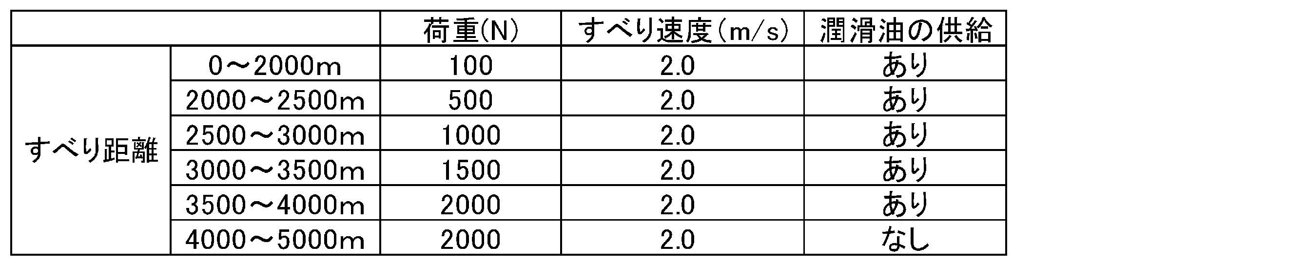
軸受試験片の摩擦係数および温度の変化を示す図を図9~11に示す。図9は実施例1の摺動部材を用いた軸受試験片の試験結果であり、図10は比較例1の摺動部材を用いた軸受試験片の試験結果であり、図11は比較例2の摺動部材を用いた軸受試験片の試験結果である。図9~11において、(1)のチャートは摩擦係数のチャートであり、(2)のチャートは軸受試験片の温度のチャートである。また、図12に実施例1、比較例1、比較例2の軸受試験片のストライベック曲線を示す。また、図13~図15に摺動試験後の軸受試験片の摺動面を示す。図13は実施例1の摺動部材を用いた軸受試験片の摺動面であり、図14は比較例1の摺動部材を用いた軸受試験片の摺動面であり、図15は比較例2の摺動部材を用いた軸受試験片の摺動面である。
図9~12の試験結果より、実施例1は、すべり距離0~2000mの一定荷重下(荷重100N)では、摩擦係数は徐々に低下し、軸受試験片の温度は50℃付近で安定していた。すべり距離2000~4000mでは、荷重を段階的に増加させたて摺動したが、摩擦係数や温度の急激な変動はなく、比較例1、2よりも安定した挙動を示していた。すべり距離4000~5000mでは、潤滑油の供給を停止して摺動したが、摩擦係数や温度の急激な変動はなかった。また、図13に示すように、良好ななじみ面が形成されていた。走査型電子顕微鏡を用いて摺動面を観察したところ、実施例1の摺動部材は、試験後もアルミ合金の表面の凹部にポリマーモノリスが残存している個所があった。
これに対し、比較例1は、すべり距離0~2000mの一定荷重下(荷重100N)では、実施例1よりも摩擦係数が大きかった。また、摩耗粉の発生量が多かった。摩耗粉はパーティクルカウンター205で測定した。すべり距離2000~4000mでは、荷重を段階的に増加させたて摺動したが、摩擦係数や温度の急激な変動が見られた。また、摩耗粉の発生量が多かった。また、比較例1の摺動部材は、アルミ合金の表面の凸部が摩耗して平滑な面が形成されていたが、摩耗粉が埋設している部位があった。
また、比較例2は、すべり距離0~2000mの一定荷重下(荷重100N)では、摩擦係数および温度は安定していた。しかしながら、すべり距離2000~4000mでは、荷重を段階的に増加させたて摺動したが、摩擦係数の急激な変動が見られた。また、温度は、すべり距離の増加とともに連続的に増加していた。また、すべり距離4000~5000mでは、潤滑油の供給を停止して摺動したが、温度が上昇して、すべり距離4500mの時点で焼付きが発生した。また、図15に示すように、比較例2の摺動部材は、ポリマーモノリスが剥離している箇所があった。更には、焼付きが発生して変形している箇所が見られた。
実施例1について、更に摺動を継続して行ったところ、表面にポリマーモノリスが確認できなくなった後も、温度の急激な上昇や、焼付けの発生や、摩擦係数の急激な上昇は見られなかった。
[試験例2]
図8に示す試験装置を用いて、実施例1および比較例1の摺動部材のすべり速度変化試験を行った。図8の符号の説明は上述の通りである。軸受試験片103として実施例1および比較例1の摺動部材をそれぞれ用いた。
図8に示す試験装置を用いて、実施例1および比較例1の摺動部材のすべり速度変化試験を行った。図8の符号の説明は上述の通りである。軸受試験片103として実施例1および比較例1の摺動部材をそれぞれ用いた。
オイル注入口(Oil inlet)の矢印の方向から58~62℃の潤滑油(基油として鉱油、添加剤として粘度指数向上剤を含む潤滑油、60℃での動粘度10.37mm2/s)を5mL/sの流量で供給し、6.0m/sのすべり速度で回転するリング試験片104に対して、上部から軸受試験片103を100Nの荷重(Load)をかけて摺動した。すべり距離が2000mに達したら荷重(Load)を500Nまで増加させて摺動した。次いで、下記表に示すように、すべり距離が2500mに達したら荷重(Load)を500Nの状態を維持しつつ、リング試験片104のすべり速度を5.5m/sに減速した。その後、すべり距離500m毎にリング試験片104のすべり速度を0.5m/sずつ減速した。すべり距離が8000mに達した時点で試験を終了した。
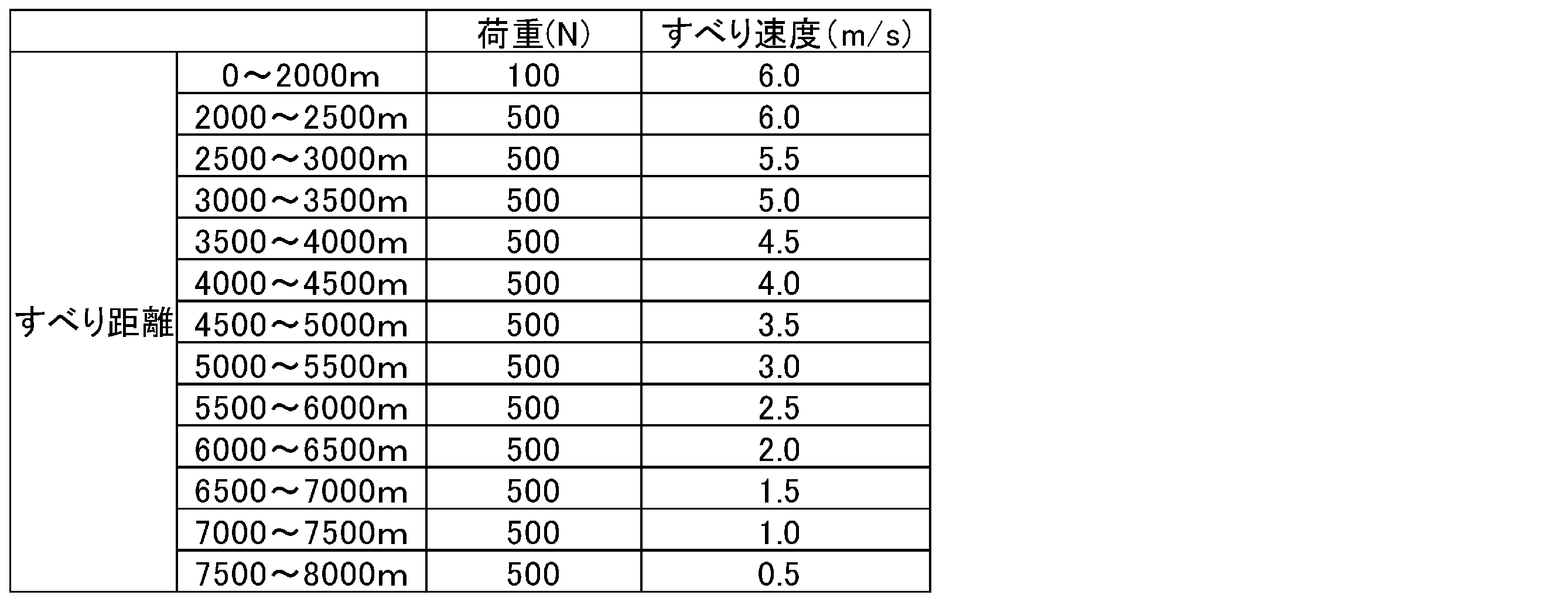
軸受試験片の摩擦係数および温度の変化を示す図を図16に示す。図16において、(1-1)のチャートは実施例1の摩擦係数のチャートであり、(1-2)のチャートは実施例1の軸受試験片の温度のチャートであり、(2-1)のチャートは比較例1の摩擦係数のチャートであり、(2-2)のチャートは比較例1の軸受試験片の温度のチャートである。また、図17に実施例1および比較例1の軸受試験片のストライベック曲線を示す。
図16の試験結果より、比較例1は、荷重を500Nに増加させた時点(すべり距離2000mの時点)において、摩擦係数および温度が急激に増加した。また、すべり速度を減速させた際に摩擦係数が急激に上昇した(特に、すべり距離が5500m、7000m、7500mの時点)。また、図17より、摩擦係数と軸受特性数に相関性が見られなかった。
一方、実施例1は、荷重を500Nに増加させた時点(すべり距離2000mの時点)において、摩擦係数の急激な増加は見られなかった。また、比較例1よりも温度上昇が抑制されていた。また、すべり速度を減速させても摩擦係数の変動がほとんどなく、安定した挙動を示していた。また、図17より、摩擦係数と軸受特性数に相関性が見られ、軸受特性数が5.33×10⁻⁹の時、摩擦係数が最小値を示した。
<摺動部材の製造>
(実施例11)
ポリアミド樹脂(MC900NC)で構成された直径30mm、厚さ2mmの円盤状の基材の表面に、レーザー加工機(オーレーザー株式会社製、PRT-HAJIMECL1)を用いて深さ50μmの波形状の条痕が300μmピッチで形成して、表面粗さRaを22μmに調整した。次に、この基材の表面に、ポリマーモノリス形成用組成物を浸漬塗布した後、110℃で60分間加熱して硬化処理を行い、次いで、180℃で30分間アニール処理を行い硬化膜を形成した。次いで、メタノール浸漬による洗浄、水に浸漬しながら研磨紙での表面除去、水洗浄の方法で硬化膜から孔形成剤を除去して連続空孔とポリマー骨格の3次元共連続構造を有するポリマーモノリスを形成して実施例11の摺動部材を製造した。得られたポリマーモノリスの最大膜厚は50μmであり、空孔率が72%であり、平均空孔径が1μmであった。
(実施例12)
実施例11の方法で得られた摺動部材の表面に、真空蒸着機(大阪真空(株)製)を用いて厚さ15nmのアルミニウム蒸着膜を形成し、実施例12の摺動部材を製造した。アルミニウム蒸着後の表面粗さRaは22μmであった。ポリマーモノリスの最大膜厚は50μmであり、空孔率が72%であり、平均空孔径が1μmであった。
実施例11の方法で得られた摺動部材の表面に、真空蒸着機(大阪真空(株)製)を用いて厚さ15nmのアルミニウム蒸着膜を形成し、実施例12の摺動部材を製造した。アルミニウム蒸着後の表面粗さRaは22μmであった。ポリマーモノリスの最大膜厚は50μmであり、空孔率が72%であり、平均空孔径が1μmであった。
(比較例11)
ポリアミド樹脂(MC900NC)で構成された直径30mm、厚さ2mmの円盤状の基材の表面に、レーザー加工機(オーレーザー株式会社製、PRT-HAJIMECL1)を用いて深さ50μmの波形状の条痕が300μmピッチで形成して、表面粗さRaを22μmに調整した。この基材を比較例11の摺動部材とした。
ポリアミド樹脂(MC900NC)で構成された直径30mm、厚さ2mmの円盤状の基材の表面に、レーザー加工機(オーレーザー株式会社製、PRT-HAJIMECL1)を用いて深さ50μmの波形状の条痕が300μmピッチで形成して、表面粗さRaを22μmに調整した。この基材を比較例11の摺動部材とした。
[試験例3]
ボールオンディスクタイプの回転式摩擦計(UMT、Bruker Co.、ボールの材質:曲率半径7.79mmのガラスレンズ)を用いて摩擦力および摩擦係数を測定した。具体的には、潤滑油(ポリ(α―オレフィン)、25℃における粘度110cP)を真空含浸させた摺動部材の表面に、回転式摩擦計のボールを10Nの荷重(Load)で押し当てた状態で、摺動部材を時計回りの方向で回転速度を500rpm~1rpmまで段階的に変化させて回転させた(すべり速度=5.2×10⁻⁴~0.26m/sに相当)のち、反時計回りの方向で、で回転速度を500~1rpmまで段階的に変化させて回転させた。摩擦力および摩擦係数は、時計回りおよび反時計回りの回転における検出値の平均によって決定した。摩擦力および摩擦係数の測定温度は25℃とした。摺動部材として、実施例11、実施例12および比較例11の摺動部材を用いた。
ボールオンディスクタイプの回転式摩擦計(UMT、Bruker Co.、ボールの材質:曲率半径7.79mmのガラスレンズ)を用いて摩擦力および摩擦係数を測定した。具体的には、潤滑油(ポリ(α―オレフィン)、25℃における粘度110cP)を真空含浸させた摺動部材の表面に、回転式摩擦計のボールを10Nの荷重(Load)で押し当てた状態で、摺動部材を時計回りの方向で回転速度を500rpm~1rpmまで段階的に変化させて回転させた(すべり速度=5.2×10⁻⁴~0.26m/sに相当)のち、反時計回りの方向で、で回転速度を500~1rpmまで段階的に変化させて回転させた。摩擦力および摩擦係数は、時計回りおよび反時計回りの回転における検出値の平均によって決定した。摩擦力および摩擦係数の測定温度は25℃とした。摺動部材として、実施例11、実施例12および比較例11の摺動部材を用いた。
図18に、実施例11、実施例12および比較例11のストライベック曲線を示す。図18に示すように、比較例11の摩擦係数は、ストライベック特性数(横軸、粘度×すべり速度/荷重)に拠らずほぼ一定であることから、高速度であっても境界潤滑、すなわち二面間が接触していると判断される。このため、初期摩擦試験においては大きな影響は見られなかったが、長期摩擦試験では摩耗の進行が懸念される。これに対し、実施例11、実施例12は、摩擦係数のストライベック特性数依存性があることから混合潤滑と判断され、二面間の接触が抑制されていると考えられる。このため、長期摩擦試験での、摩耗の進行を抑制できると考えられる。
1:基材
2:ポリマーモノリス
10:摺動部材
11:軸受
21:潤滑油
31:回転軸
50:軸受システム
101:アコースティックエミッションセンサー
102:サーモカップラ
103:軸受試験片
104:リング試験片
201:トルクメータ
202:オイルバス
203:シャフト
204:スイングパーツ
205:パーティクルカウンター
2:ポリマーモノリス
10:摺動部材
11:軸受
21:潤滑油
31:回転軸
50:軸受システム
101:アコースティックエミッションセンサー
102:サーモカップラ
103:軸受試験片
104:リング試験片
201:トルクメータ
202:オイルバス
203:シャフト
204:スイングパーツ
205:パーティクルカウンター
Claims (19)
- 相手部材との摺動側の表面の表面粗さRaが0.5~1000μmである基材の前記摺動側の表面にポリマーモノリスが形成された摺動部材。
- 前記ポリマーモノリスは潤滑油を含む、請求項1に記載の摺動部材。
- 前記ポリマーモノリスのポリマー骨格は、2官能以上のエポキシ化合物と2官能以上のアミン化合物の重合物である、請求項1または2に記載の摺動部材。
- 前記ポリマーモノリスの空孔率が30%以上である、請求項1~3のいずれか1項に記載の摺動部材。
- 前記ポリマーモノリスの平均空孔径が0.01~100μmである、請求項1~4のいずれか1項に記載の摺動部材。
- 前記ポリマーモノリスは、更にシリカ粒子を含む、請求項1~5のいずれか1項に記載の摺動部材。
- 前記基材は金属基材である、請求項1~6のいずれか1項に記載の摺動部材。
- 前記基材の前記摺動側の表面には凹凸が形成されて表面粗さRaが0.5~1000μmとされており、
前記基材の前記摺動側の表面の凹部の少なくとも一部に前記ポリマーモノリスを有している、請求項1~7のいずれか1項に記載の摺動部材。 - 前記基材の前記摺動側の表面の凹部の少なくとも一部に前記ポリマーモノリスを有し、かつ、前記基材の前記摺動側の表面の少なくとも一部が前記ポリマーモノリスから露出している、請求項8に記載の摺動部材。
- 前記基材の前記摺動側の表面には、条痕が形成されている、請求項1~9のいずれか1項に記載の摺動部材。
- 前記ポリマーモノリスの最大膜厚が2000μm以下である、請求項1~10のいずれか1項に記載の摺動部材。
- 前記摺動部材はすべり軸受である、請求項1~11のいずれか1項に記載の摺動部材。
- 相手部材との摺動側の表面の表面粗さRaが0.5~1000μmである基材の前記摺動側の表面に、重合性化合物と架橋剤と孔形成剤とを含むポリマーモノリス形成用組成物を塗布して塗布膜を形成し、前記塗布膜を硬化し、硬化により形成された硬化膜から前記孔形成剤を除去してポリマーモノリスを形成する、摺動部材の製造方法。
- 前記基材の前記摺動側の表面には凹凸が形成されて表面粗さRaが0.5~1000μmとされており、
前記基材の前記摺動側の表面の凹部の少なくとも一部に前記ポリマーモノリスを形成する、請求項13に記載の摺動部材の製造方法。 - 前記基材の前記摺動側の表面の凹部の少なくとも一部に前記ポリマーモノリスを形成するとともに、前記基材の前記摺動側の表面の少なくとも一部を前記ポリマーモノリスから露出させる、請求項13に記載の摺動部材の製造方法。
- 前記重合性化合物は2官能以上のエポキシ化合物であり、前記架橋剤は2官能以上のアミン化合物である、請求項13~15のいずれか1項に記載の摺動部材の製造方法。
- 前記ポリマーモノリス形成用組成物は、更にシリカ粒子を含む、請求項13~16のいずれか1項に記載の摺動部材の製造方法。
- 前記ポリマーモノリス形成用組成物は、更に沸点が100℃以下の有機溶剤を含む、請求項13~17のいずれか1項に記載の摺動部材の製造方法。
- すべり軸受と、
前記すべり軸受けの内周面側に設けられた回転軸と、
前記すべり軸と前記回転軸との間に介在する潤滑油と、を備えた摺動システムであって、
前記すべり軸受が、請求項1~12のいずれか1項に記載の摺動部材である、摺動システム。
Priority Applications (1)
| Application Number | Priority Date | Filing Date | Title |
|---|---|---|---|
| JP2020568183A JP7527006B2 (ja) | 2019-01-25 | 2020-01-22 | 摺動部材、摺動部材の製造方法および摺動システム |
Applications Claiming Priority (2)
| Application Number | Priority Date | Filing Date | Title |
|---|---|---|---|
| JP2019-010938 | 2019-01-25 | ||
| JP2019010938 | 2019-01-25 |
Publications (1)
| Publication Number | Publication Date |
|---|---|
| WO2020153394A1 true WO2020153394A1 (ja) | 2020-07-30 |
Family
ID=71735587
Family Applications (1)
| Application Number | Title | Priority Date | Filing Date |
|---|---|---|---|
| PCT/JP2020/002077 Ceased WO2020153394A1 (ja) | 2019-01-25 | 2020-01-22 | 摺動部材、摺動部材の製造方法および摺動システム |
Country Status (2)
| Country | Link |
|---|---|
| JP (1) | JP7527006B2 (ja) |
| WO (1) | WO2020153394A1 (ja) |
Cited By (1)
| Publication number | Priority date | Publication date | Assignee | Title |
|---|---|---|---|---|
| JP2021193290A (ja) * | 2020-06-08 | 2021-12-23 | 東芝キヤリア株式会社 | 圧縮機及び冷凍サイクル装置 |
Citations (5)
| Publication number | Priority date | Publication date | Assignee | Title |
|---|---|---|---|---|
| JP2010111791A (ja) * | 2008-11-07 | 2010-05-20 | Kyoto Univ | 有機多孔体及びその製造方法 |
| JP2010286038A (ja) * | 2009-06-11 | 2010-12-24 | National Institute Of Advanced Industrial Science & Technology | 摺動用構造部材及びその製造方法 |
| JP2016166273A (ja) * | 2015-03-09 | 2016-09-15 | 株式会社エマオス京都 | 多孔質モノリスコーティング構造物及びその製造方法 |
| JP2017066526A (ja) * | 2015-09-30 | 2017-04-06 | 新日鉄住金化学株式会社 | 金属複合体層を有する部材の製造方法、及び、アルミニウム−ニッケル複合体層を有する部材 |
| WO2018225693A1 (ja) * | 2017-06-06 | 2018-12-13 | 独立行政法人国立高等専門学校機構 | ポリマーブラシ層の形成方法 |
-
2020
- 2020-01-22 WO PCT/JP2020/002077 patent/WO2020153394A1/ja not_active Ceased
- 2020-01-22 JP JP2020568183A patent/JP7527006B2/ja active Active
Patent Citations (5)
| Publication number | Priority date | Publication date | Assignee | Title |
|---|---|---|---|---|
| JP2010111791A (ja) * | 2008-11-07 | 2010-05-20 | Kyoto Univ | 有機多孔体及びその製造方法 |
| JP2010286038A (ja) * | 2009-06-11 | 2010-12-24 | National Institute Of Advanced Industrial Science & Technology | 摺動用構造部材及びその製造方法 |
| JP2016166273A (ja) * | 2015-03-09 | 2016-09-15 | 株式会社エマオス京都 | 多孔質モノリスコーティング構造物及びその製造方法 |
| JP2017066526A (ja) * | 2015-09-30 | 2017-04-06 | 新日鉄住金化学株式会社 | 金属複合体層を有する部材の製造方法、及び、アルミニウム−ニッケル複合体層を有する部材 |
| WO2018225693A1 (ja) * | 2017-06-06 | 2018-12-13 | 独立行政法人国立高等専門学校機構 | ポリマーブラシ層の形成方法 |
Cited By (2)
| Publication number | Priority date | Publication date | Assignee | Title |
|---|---|---|---|---|
| JP2021193290A (ja) * | 2020-06-08 | 2021-12-23 | 東芝キヤリア株式会社 | 圧縮機及び冷凍サイクル装置 |
| JP7486741B2 (ja) | 2020-06-08 | 2024-05-20 | 東芝キヤリア株式会社 | 圧縮機及び冷凍サイクル装置 |
Also Published As
| Publication number | Publication date |
|---|---|
| JP7527006B2 (ja) | 2024-08-02 |
| JPWO2020153394A1 (ja) | 2021-12-02 |
Similar Documents
| Publication | Publication Date | Title |
|---|---|---|
| JP6899916B2 (ja) | グラフェン含有被膜潤滑剤 | |
| US5262241A (en) | Surface coated products | |
| US8883697B2 (en) | Wear resistant lubricious composite | |
| JP6338035B1 (ja) | 転がり軸受及びその製造方法 | |
| JP6591820B2 (ja) | フォイル軸受 | |
| US20120058923A1 (en) | Self-Lubricating Surface Coating Composition for Low Friction or Soft Substrate Applications | |
| WO1992008062A1 (fr) | Palier a gaz du type dynamique | |
| JP7527006B2 (ja) | 摺動部材、摺動部材の製造方法および摺動システム | |
| US6090869A (en) | Self-lubricating coating composition of epoxy resins, polytetrafluoroethylene, MoS2 and mica | |
| Wang et al. | Long-term stable superlubricity coatings enabled by the interaction between the polydimethylsiloxane brush and silicone oil | |
| CN116615611A (zh) | 滚动轴承 | |
| Başaran et al. | Comparative study on the thermal and tribological properties of PA12 and PA11 for coating applications | |
| EP4194382B1 (en) | Conveying belt | |
| CN115521708A (zh) | 一种基于聚二甲基硅氧烷聚合物分子刷的超润滑涂层及其制备方法 | |
| WO2007135956A1 (ja) | 表面が非粘着処理された積層体及びその用途 | |
| WO2012168354A1 (en) | Improved seal | |
| WO2017164399A1 (ja) | 転がり軸受用保持器および転がり軸受 | |
| JP7486741B2 (ja) | 圧縮機及び冷凍サイクル装置 | |
| CN110662826A (zh) | 润滑脂组合物以及用其涂覆的滑动构件 | |
| JP4281948B2 (ja) | 転がり軸受の製造方法 | |
| JP2012012480A (ja) | プラスチックの耐摩耗性を向上させる潤滑被膜及びその被膜を形成するための塗料 | |
| WO2005118730A1 (ja) | 摺動部材用水系塗料および摺動部材 | |
| JP4543742B2 (ja) | 固体潤滑剤及び摺動部材 | |
| JPH0830490B2 (ja) | 動圧流体軸受 | |
| EP3615621A2 (en) | Bearing material, bearing and method |
Legal Events
| Date | Code | Title | Description |
|---|---|---|---|
| 121 | Ep: the epo has been informed by wipo that ep was designated in this application |
Ref document number: 20744238 Country of ref document: EP Kind code of ref document: A1 |
|
| ENP | Entry into the national phase |
Ref document number: 2020568183 Country of ref document: JP Kind code of ref document: A |
|
| NENP | Non-entry into the national phase |
Ref country code: DE |
|
| 122 | Ep: pct application non-entry in european phase |
Ref document number: 20744238 Country of ref document: EP Kind code of ref document: A1 |