WO2020152952A1 - Appareillage à isolation gazeuse et son procédé de fabrication - Google Patents
Appareillage à isolation gazeuse et son procédé de fabrication Download PDFInfo
- Publication number
- WO2020152952A1 WO2020152952A1 PCT/JP2019/044297 JP2019044297W WO2020152952A1 WO 2020152952 A1 WO2020152952 A1 WO 2020152952A1 JP 2019044297 W JP2019044297 W JP 2019044297W WO 2020152952 A1 WO2020152952 A1 WO 2020152952A1
- Authority
- WO
- WIPO (PCT)
- Prior art keywords
- insulated switchgear
- resistance material
- gas
- tank
- resin layer
- Prior art date
Links
Images


Classifications
-
- H—ELECTRICITY
- H02—GENERATION; CONVERSION OR DISTRIBUTION OF ELECTRIC POWER
- H02B—BOARDS, SUBSTATIONS OR SWITCHING ARRANGEMENTS FOR THE SUPPLY OR DISTRIBUTION OF ELECTRIC POWER
- H02B13/00—Arrangement of switchgear in which switches are enclosed in, or structurally associated with, a casing, e.g. cubicle
- H02B13/02—Arrangement of switchgear in which switches are enclosed in, or structurally associated with, a casing, e.g. cubicle with metal casing
- H02B13/035—Gas-insulated switchgear
- H02B13/055—Features relating to the gas
Definitions
- the present invention relates to a gas insulated switchgear and a manufacturing method thereof.
- main circuit devices such as a power receiving disconnector, a circuit breaker, and a busbar disconnecting switch are housed in a hermetically sealed container in which an insulating gas such as sulfur hexafluoride (SF 6 ) is sealed.
- the respective devices are connected by a main circuit conductor.
- the main circuit conductor is supported in the gas by an insulator installed in the container, and maintains insulation between the main circuit conductor and the closed container having the ground potential.
- gas-insulated switchgear for power reception, power is drawn from the power system by a power cable or overhead wire, and power is supplied to the busbar via the power disconnector-circuit breaker-busbar disconnector. Further, in the case of a gas-insulated switchgear for power supply, power is received from the bus bar and power is supplied to the power cable or overhead line connected to the load via the bus bar disconnector-circuit breaker-power supply disconnector.
- a gas-insulated switchgear that configures one bay for three phases and one gas-insulated switchgear that configures an adjacent one bay are electrically connected by a bus bar.
- a gas insulated switchgear having an airtight container enclosing an insulating gas, and a main circuit conductor housed inside the airtight container, by forming a resin layer containing a non-linear resistance material on the inner surface of the airtight container. It has been studied to solve the problem that a high electric field is generated around a metal foreign substance generated inside a closed container and the metal foreign substance floats.
- Patent Document 1 a grounding tank filled with an insulating gas, a central conductor arranged inside the grounding tank, and a lower inner surface of the grounding tank are arranged.
- the insulating material contains a non-linear resistance material.
- a non-linear resistance part wherein the non-linear resistance part contains more non-linear resistance material on the center conductor side than on the ground tank side.
- Patent Document 1 electric field-conductivity characteristics that differ depending on the type of non-linear resistance material have not been sufficiently investigated.
- ⁇ Materials with low electric field that show non-linearity have gradual increase rate of conductivity, small relaxation effect in high electric field region, and partial discharge easily occurs. Further, a material having a steep increase rate of conductivity has a relatively high electric field in which non-linearity appears, and has a small mitigation effect when the electric field is low.
- the purpose of the present invention is to reliably suppress the floating of metallic foreign matter generated inside the gas insulated switchgear and adhering to the inner surface of the tank, and to maintain high dielectric strength.
- the gas-insulated switchgear of the present invention has a grounded tank, and a high-voltage conductor installed inside the tank and insulated from the tank.
- a first non-linear resistance material which is a non-linear resistance material of at least one kind among plural kinds of non-linear resistance materials, in which a resin layer having a structure in which resistance materials are mixed is formed
- the second non-linear resistance material which is another kind of non-linear resistance material, has a higher operating electric field and a larger slope of the non-linear characteristic curve in the electric field range higher than the operating electric field.
- the present invention it is possible to reliably suppress the floating of metallic foreign matter generated inside the gas-insulated switchgear and adhering to the inner surface of the tank, and to maintain high dielectric strength.
- FIG. 7 is a graph showing electric field-conductivity characteristics of zinc oxide, which is a nonlinear resistance material.
- 5 is a graph showing electric field-conductivity characteristics of silicon carbide, which is a nonlinear resistance material.
- 6 is a graph showing electric field-conductivity characteristics when two types of nonlinear resistance materials are mixed. 6 is a graph showing electric field-conductivity characteristics when the addition amount of the nonlinear resistance material is used as a parameter. It is a graph which shows the result of the levitation test at the time of installing a metallic foreign substance in a tank. It is a flowchart which shows an example of the formation process of the resin layer of this invention.
- the present invention relates to a coating technology inside a tank of a gas-insulated switchgear, and more specifically, a circuit breaker and a disconnector are installed in a gas-insulated hermetic container, and a power receiving unit that receives power from a power system, and a circuit breaker and a disconnector
- the present invention relates to coating of a non-linear resistance material inside a tank used in a gas insulated switchgear having a power supply unit that is installed in an insulating container and supplies power to a load side via a bus bar.
- FIG. 1 is a partial cross-sectional view showing the overall configuration of the gas insulated switchgear of the present invention.
- a gas-insulated switchgear 100 includes a ground tank 2 (hereinafter, also simply referred to as “tank”) filled with an insulating gas (SF 6 or the like), and a high-voltage conductor provided inside the ground tank 2. 1 and an insulating spacer 30 (hereinafter, also simply referred to as “spacer”) that supports and fixes the high-voltage conductor 1 inside the ground tank 2.
- the gas-insulated switchgear 100 includes a circuit breaker 20, a disconnector 21, a ground switch 22, a current transformer 23, a transformer 24, buses 25 and 26, and the like. Dry air is also used as the insulating gas filled in the tank.
- the high-voltage conductor 1 is made of a cylindrical metal (aluminum, copper, etc.).
- the grounding tank 2 is a cylindrical metal container.
- the high voltage conductor 1 is supported and fixed by an insulating spacer 30 inside the ground tank 2 and is insulated from the ground tank 2. Since the ground tank 2 is grounded, the potential is normally 0.
- a cone type (cone spacer) is shown as the insulating spacer 30, but other than this, there are various shapes such as a disk-shaped spacer and a columnar post spacer.
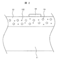
- FIG. 2 is a schematic cross-sectional view showing a part of the tank of the gas insulated switchgear of the present invention.
- a resin layer 53 is provided on the inner surface of the tank wall 51.
- the resin layer 53 is formed by coating a mixture of epoxy resin or the like with the nonlinear resistance materials 121 and 122 added and mixed.
- the nonlinear resistance materials 121 and 122 zinc oxide (ZnO), silicon carbide (SiC), barium titanate (BaTiO 3 ), diamond or the like is used.
- the nonlinear resistance materials 121 and 122 are in the form of particles and are composed of two or more kinds having different compositions.
- foreign matter 54 may adhere to the inner surface of the tank wall 51.
- FIG. 3 is a cross-sectional view showing an example of the arrangement of the resin layer 53 of FIG.
- the resin layer 53 is provided in the lower half region of the inner surface of the tank wall 51.
- a resin epoxy resin or the like
- a resin layer 131 insulating resin layer. Since the foreign metal particles often fall downward due to gravity, it is often sufficient to provide the resin layer 53 in the lower half region. Further, by partially providing the resin layer 53 in this manner, the manufacturing cost can be suppressed.
- the resin layer 53 may also be provided in the upper half region of the inner surface of the tank wall 51. In some cases, the resin layer 53 may be provided in the entire area of the lower half and a part of the area of the upper half. It is desirable that the resin layer 53 be provided in at least the entire lower half region.
- the thickness of the resin layer 53 is preferably 50 ⁇ m or more.
- the thickness of the resin layer 53 is preferably 1 mm or less, more preferably 200 ⁇ m or less from the viewpoints of the dimensions in the tank, material costs, and the like.
- FIG. 4 is a graph showing electric field-conductivity characteristics of zinc oxide, which is an example of a nonlinear resistance material.
- the horizontal axis represents the electric field and the vertical axis represents the conductivity.
- the concentration of zinc oxide in the resin layer is 10% by mass.
- zinc oxide has a non-linear electric field-conductivity characteristic (non-linear characteristic).
- non-linear characteristic the electric field at which the steep rise of the electric field-conductivity curve starts (hereinafter referred to as “operating electric field”) is about 7 kV/mm. That is, in the case of zinc oxide, when the electric field is about 7 kV/mm, the slope of the nonlinear characteristic curve (hereinafter, also simply referred to as “curve”) becomes steep, the curve rises, and the conductivity sharply rises.
- the value of the electric field at which the rate of change (second derivative) of the slope of the curve starts to increase above a predetermined value may be used.
- the operating electric field can be calculated by expressing the approximate expression of the curve with a Taylor polynomial of third or higher order and calculating the second derivative.
- the operating electric field changes not only with the type of nonlinear resistance material, but also with the concentration of the nonlinear resistance material in the resin. Therefore, when comparing operating electric fields for different types of non-linear resistance materials, in the present specification, non-linear characteristic curves measured at the same concentration on the mass basis and mixed with the same resin will be compared. .. Therefore, it can be expressed that the first nonlinear resistance material has a higher operating electric field than the second nonlinear resistance material, and that the slope of the nonlinear characteristic curve is large in the range of the electric field higher than the operating electric field.
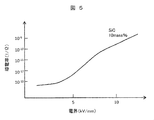
- FIG. 5 is a graph showing electric field-conductivity characteristics of silicon carbide, which is a nonlinear resistance material.
- the concentration of silicon carbide in the resin layer is 10% by mass.
- the operating electric field is low and the slope of the curve is relatively gentle.
- the rise of the curve is about 4 kV/mm, and the slope of the curve becomes gentle at about 8 kV/mm or more.
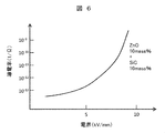
- FIG. 6 is a graph showing electric field-conductivity characteristics when two types of nonlinear resistance materials are mixed.
- the zinc oxide concentration in the resin layer is 10% by mass, and the silicon carbide concentration is 10% by mass.
- the slope of the curve starts to increase at about 4 kV/mm, and further increases at about 7 kV/mm or more.
- the resin (coating material) containing the nonlinear resistance material is applied to the inner surface of the tank wall 51 by spray coating or brush coating.
- the first non-linear resistance material zinc oxide
- the second non-linear resistance material silicon carbide
- the slope of the characteristic curve is large.
- the curve of FIG. 6 has a shape in which the curves of FIGS. 4 and 5 are superposed. Therefore, an appropriate conductivity and operating electric field can be obtained.
- the operating electric field of the resin layer of this example is preferably 3 kV/mm or more. This is because if the operating electric field is too low, the insulating function of the resin layer will be insufficient.
- the operating electric field of the resin layer of this example is preferably 5 kV/mm or less.
- the operating electric field of the resin layer corresponds to the desired range of the operating electric field of the second nonlinear resistance material.
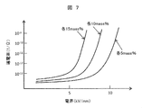
- FIG. 7 is a graph showing electric field-conductivity characteristics when the additive amount of the nonlinear resistance material is used as a parameter.
- zinc oxide and silicon carbide are added to the resin layer so as to have equal concentrations, and the respective concentrations are 5% by mass, 10% by mass, and 15% by mass. That is, when the concentration of zinc oxide is 5% by mass and the concentration of silicon carbide is 5% by mass (each 5% by mass), the concentration of zinc oxide is 10% by mass and the concentration of silicon carbide is 10% by mass ( 10% by mass), the concentration of zinc oxide is 15% by mass, and the concentration of silicon carbide is 15% by mass (15% by mass each).
- the electric field-conductivity characteristics of the coating material change depending on the addition amount of the nonlinear resistance material. Specifically, the start of the rising of the curve (operating electric field) is about 7 kV/mm for each 5 mass %, about 5 kV/mm for each 10 mass %, and about 4 kV/mm for each 15 mass %.
- the increase in conductivity during electric field concentration may be insufficient when foreign matter is present on the inner surface of the tank wall, and electric field relaxation may not occur.
- the total addition amount of a plurality of types of non-linear resistance materials is in the range of 5% by mass to 50% by mass, the electric field relaxation effect, the electric field-conductivity characteristic, and the viscosity of the coating material in the coating operation. Is preferred.
- the addition amount of the nonlinear resistance material is more preferably in the range of 5% by mass to 20% by mass, and particularly preferably in the range of 5% by mass to 15% by mass.
- the mixing ratio of the non-linear resistance material having a low operating electric field (eg, silicon carbide) and the non-linear resistance material having a high operating electric field (eg, zinc oxide) is between 1:4 and 4:1. It is preferable because it has characteristics and an electric field relaxation effect occurs around the foreign matter.
- This mixing ratio is more preferably 1:3 to 3:1, and particularly preferably 1:2 to 2:1.
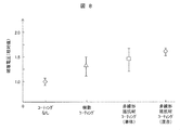
- FIG. 8 is a graph showing the result of the levitation test when the metallic foreign matter is installed in the tank.
- the vertical axis represents the relative value of the breakdown voltage.
- the breakdown voltage means a voltage at which the metallic foreign matter floats up under a predetermined condition. This voltage is also called a metal foreign matter levitating voltage.
- the value of the floating electric field of foreign matter when the inner surface of the tank wall is a metal surface (without coating) is set to 1.0.
- the floating electric field When coated with an insulating film made of only resin (resin coating), the floating electric field has an average value of about 1.3 and a variation of about 20%.
- non-linear resistance material coating single body
- the average value increases to about 1.5, but the variation is about 20%, which is equivalent to resin coating.
- the coating material containing two types of non-linear resistance materials (zinc oxide and silicon carbide) according to the present embodiment is applied (non-linear resistance material coating (mixing))
- the average value of the levitation electric field is 1 6 or more, and the variation is as small as about 5%. This means that the smaller the variation is, the higher the average value is, and the floating of the metallic foreign matter does not occur at a low voltage. As a result, even if the metallic foreign matter is present inside the tank, the floating of the metallic foreign matter can be restricted and a high dielectric strength can be maintained.
- FIG. 9 is a flow chart showing an example of the resin layer forming process of the present invention.
- the surface treatment agent and the non-linear resistance material are mixed (S101).
- This mixture is added to the resin (S102).
- This is stirred (S103).
- a silane coupling agent is an example of the surface treatment agent.
- a resin curing agent is also mixed.
- the nonlinear resistance material is uniformly dispersed in the resin after the stirring in step S103. Therefore, in the range where the coating material is applied, the electric field relaxation effect around the metallic foreign matter is effective. As a result, the effect of improving the floating electric field of the metallic foreign matter is stabilized.
- the addition amount of the surface treatment agent is preferably in the range of 0.1% by mass to 5% by mass.
- the above coating material may be applied as an undercoat on the inner surface of the tank by using an insulating resin alone that does not contain the non-linear resistance material, and then on the applied surface.
- an insulating resin alone that does not contain the non-linear resistance material
- the insulating resin layer formed by the undercoat prevents the charge from being charged from the tank to the foreign matter, and the resin layer containing the non-linear resistance material can alleviate the electric field concentration and suppress the partial discharge.
- the thickness of the insulating resin layer is preferably 30 ⁇ m or more.
- the thickness of the resin layer (coating layer) containing the nonlinear resistance material is preferably 50 ⁇ m or more.
- the thickness of each of these layers is preferably 1 mm or less, more preferably 200 ⁇ m or less, from the viewpoints of the dimensions in the tank, material costs, and the like. This upper limit is the same for the coating layer alone.
Landscapes
- Engineering & Computer Science (AREA)
- Power Engineering (AREA)
- Gas-Insulated Switchgears (AREA)
- Installation Of Bus-Bars (AREA)
Abstract
L'invention concerne un appareillage à isolation gazeuse comprenant un réservoir mis à la terre, et un conducteur haute tension installé à l'intérieur du réservoir et isolé du réservoir, dans lequel : une couche de résine ayant une configuration dans laquelle une pluralité de types de matériaux de résistance non linéaires sont mélangés avec de la résine est formée sur la surface interne du réservoir ; et un premier matériau de résistance non linéaire, qui est au moins un type de matériau de résistance non linéaire parmi la pluralité de types de matériaux de résistance non linéaire, présente un champ électrique au fonctionnement plus élevé et une pente plus élevée d'une courbe caractéristique non linéaire dans la plage d'un champ électrique plus élevé que le champ électrique de fonctionnement qu'un second matériau de résistance non linéaire, qui est au moins un autre type de matériau de résistance non linéaire parmi la pluralité de types de matériaux de résistance non linéaire. Par conséquent, il est possible de supprimer de manière fiable le flottement de la matière étrangère métallique générée à l'intérieur de l'appareillage à isolation gazeuse et d'adhérer à la surface interne du réservoir, et de maintenir une rigidité diélectrique élevée.
Applications Claiming Priority (2)
| Application Number | Priority Date | Filing Date | Title |
|---|---|---|---|
| JP2019-008385 | 2019-01-22 | ||
| JP2019008385A JP7137486B2 (ja) | 2019-01-22 | 2019-01-22 | ガス絶縁開閉装置及びその製造方法 |
Publications (1)
| Publication Number | Publication Date |
|---|---|
| WO2020152952A1 true WO2020152952A1 (fr) | 2020-07-30 |
Family
ID=71736132
Family Applications (1)
| Application Number | Title | Priority Date | Filing Date |
|---|---|---|---|
| PCT/JP2019/044297 WO2020152952A1 (fr) | 2019-01-22 | 2019-11-12 | Appareillage à isolation gazeuse et son procédé de fabrication |
Country Status (2)
| Country | Link |
|---|---|
| JP (1) | JP7137486B2 (fr) |
| WO (1) | WO2020152952A1 (fr) |
Citations (3)
| Publication number | Priority date | Publication date | Assignee | Title |
|---|---|---|---|---|
| JP2014156587A (ja) * | 2013-01-18 | 2014-08-28 | Toshiba Corp | 非直線抵抗塗料、母線および固定子コイル |
| WO2015136753A1 (fr) * | 2014-03-12 | 2015-09-17 | 三菱電機株式会社 | Dispositif de commutation à isolation gazeuse |
| JP2018196280A (ja) * | 2017-05-19 | 2018-12-06 | 株式会社日立製作所 | 絶縁スペーサ及びそれを用いたガス絶縁開閉装置 |
-
2019
- 2019-01-22 JP JP2019008385A patent/JP7137486B2/ja active Active
- 2019-11-12 WO PCT/JP2019/044297 patent/WO2020152952A1/fr active Application Filing
Patent Citations (3)
| Publication number | Priority date | Publication date | Assignee | Title |
|---|---|---|---|---|
| JP2014156587A (ja) * | 2013-01-18 | 2014-08-28 | Toshiba Corp | 非直線抵抗塗料、母線および固定子コイル |
| WO2015136753A1 (fr) * | 2014-03-12 | 2015-09-17 | 三菱電機株式会社 | Dispositif de commutation à isolation gazeuse |
| JP2018196280A (ja) * | 2017-05-19 | 2018-12-06 | 株式会社日立製作所 | 絶縁スペーサ及びそれを用いたガス絶縁開閉装置 |
Also Published As
| Publication number | Publication date |
|---|---|
| JP7137486B2 (ja) | 2022-09-14 |
| JP2020120463A (ja) | 2020-08-06 |
Similar Documents
| Publication | Publication Date | Title |
|---|---|---|
| US7262367B2 (en) | High voltage bushing with field control material | |
| EP2937958B1 (fr) | Équipement électrique isolé par gaz | |
| JP5705384B1 (ja) | ガス絶縁機器 | |
| JP5710080B2 (ja) | ガス絶縁開閉装置 | |
| JPWO2016080018A1 (ja) | ガス絶縁開閉装置 | |
| EP3098919B1 (fr) | Appareil électrique à isolation gazeuse | |
| WO2020152952A1 (fr) | Appareillage à isolation gazeuse et son procédé de fabrication | |
| JP6352782B2 (ja) | 絶縁スペーサ | |
| JP2004335390A (ja) | コーン形絶縁スペーサ | |
| JP6807276B2 (ja) | 絶縁スペーサ及びそれを用いたガス絶縁開閉装置 | |
| JP3897972B2 (ja) | 電気機器のケーブル終端接続構造 | |
| WO2019123889A1 (fr) | Dispositif d'ouverture/fermeture | |
| JPS6023569B2 (ja) | ガス絶縁電気装置 | |
| WO2017098553A1 (fr) | Appareil d'isolation de gaz | |
| JP7418672B1 (ja) | 絶縁機器 | |
| JP7278997B2 (ja) | ガス絶縁開閉装置 | |
| JP7400113B2 (ja) | ガス絶縁機器 | |
| JPH0345111A (ja) | ガス絶縁機器 | |
| UA127036C2 (uk) | Полімерний ізолятор (варіанти) | |
| JP2006320196A (ja) | ケーブル終端接続構造 | |
| US1715889A (en) | Insulator | |
| WO2019093071A1 (fr) | Appareillage de commutation à isolation gazeuse | |
| UA139361U (uk) | Полімерний ізолятор | |
| JP5395038B2 (ja) | ガス絶縁電気機器 | |
| UA141542U (uk) | Полімерний ізолятор |
Legal Events
| Date | Code | Title | Description |
|---|---|---|---|
| 121 | Ep: the epo has been informed by wipo that ep was designated in this application |
Ref document number: 19911325 Country of ref document: EP Kind code of ref document: A1 |
|
| NENP | Non-entry into the national phase |
Ref country code: DE |
|
| 122 | Ep: pct application non-entry in european phase |
Ref document number: 19911325 Country of ref document: EP Kind code of ref document: A1 |