WO2020152952A1 - Gas insulated switchgear and manufacturing method thereof - Google Patents
Gas insulated switchgear and manufacturing method thereof Download PDFInfo
- Publication number
- WO2020152952A1 WO2020152952A1 PCT/JP2019/044297 JP2019044297W WO2020152952A1 WO 2020152952 A1 WO2020152952 A1 WO 2020152952A1 JP 2019044297 W JP2019044297 W JP 2019044297W WO 2020152952 A1 WO2020152952 A1 WO 2020152952A1
- Authority
- WO
- WIPO (PCT)
- Prior art keywords
- insulated switchgear
- resistance material
- gas
- tank
- resin layer
- Prior art date
Links
Images


Classifications
-
- H—ELECTRICITY
- H02—GENERATION; CONVERSION OR DISTRIBUTION OF ELECTRIC POWER
- H02B—BOARDS, SUBSTATIONS OR SWITCHING ARRANGEMENTS FOR THE SUPPLY OR DISTRIBUTION OF ELECTRIC POWER
- H02B13/00—Arrangement of switchgear in which switches are enclosed in, or structurally associated with, a casing, e.g. cubicle
- H02B13/02—Arrangement of switchgear in which switches are enclosed in, or structurally associated with, a casing, e.g. cubicle with metal casing
- H02B13/035—Gas-insulated switchgear
- H02B13/055—Features relating to the gas
Abstract
Provided is a gas insulated switchgear comprising a grounded tank, and a high-voltage conductor installed inside the tank and insulated from the tank, wherein: a resin layer having a configuration in which a plurality of types of non-linear resistance materials are mixed with resin is formed on the inner surface of the tank; and a first non-linear resistance material, which is at least one type of non-linear resistance material among the plurality of types of non-linear resistance materials, has a higher operating electric field and a higher slope of a non-linear characteristic curve in the range of an electric field higher than the operating electric field than a second non-linear resistance material, which is at least one other type of non-linear resistance material among the plurality of types of non-linear resistance materials. As a result, it is possible to reliably suppress the floating of the metallic foreign matter generated inside the gas insulated switchgear and adhering to the inner surface of the tank, and to maintain a high dielectric strength.
Description
本発明は、ガス絶縁開閉装置及びその製造方法に関する。
The present invention relates to a gas insulated switchgear and a manufacturing method thereof.
ガス絶縁開閉装置は、受電用断路器、遮断器、母線用断路器等の主回路機器が、六フッ化硫黄(SF6)などの絶縁性ガスを封入した密閉容器内に収容されている。各機器間は、主回路導体により接続されている。主回路導体は、容器内に設置した絶縁物によりガス中で支持され、接地電位である密閉容器との間で絶縁を保持している。
In the gas insulated switchgear, main circuit devices such as a power receiving disconnector, a circuit breaker, and a busbar disconnecting switch are housed in a hermetically sealed container in which an insulating gas such as sulfur hexafluoride (SF 6 ) is sealed. The respective devices are connected by a main circuit conductor. The main circuit conductor is supported in the gas by an insulator installed in the container, and maintains insulation between the main circuit conductor and the closed container having the ground potential.
受電用のガス絶縁開閉装置においては、電力ケーブルあるいは架空線により電力系統から電力を引き込み、受電用断路器-遮断器-母線用断路器を経由して母線に給電する。また、給電用のガス絶縁開閉装置の場合は、母線から受電し、母線用断路器-遮断器-給電用断路器を経由して負荷に接続した電力ケーブルあるいは架空線に給電する。三相分を一回線とした1ベイを構成するガス絶縁開閉装置と、隣接する1ベイを構成するガス絶縁開閉装置との間は、母線により電気的に接続される。
In the gas-insulated switchgear for power reception, power is drawn from the power system by a power cable or overhead wire, and power is supplied to the busbar via the power disconnector-circuit breaker-busbar disconnector. Further, in the case of a gas-insulated switchgear for power supply, power is received from the bus bar and power is supplied to the power cable or overhead line connected to the load via the bus bar disconnector-circuit breaker-power supply disconnector. A gas-insulated switchgear that configures one bay for three phases and one gas-insulated switchgear that configures an adjacent one bay are electrically connected by a bus bar.
絶縁性ガスを封入した密閉容器と、密閉容器の内部に収容された主回路導体と、を有するガス絶縁開閉装置においては、密閉容器の内面に、非線形抵抗材を含む樹脂層を形成することにより、密閉容器の内部で発生する金属異物の周辺に高電界が発生し、金属異物が浮上する、という問題を解決することが検討されている。
In a gas insulated switchgear having an airtight container enclosing an insulating gas, and a main circuit conductor housed inside the airtight container, by forming a resin layer containing a non-linear resistance material on the inner surface of the airtight container. It has been studied to solve the problem that a high electric field is generated around a metal foreign substance generated inside a closed container and the metal foreign substance floats.
特許文献1には、絶縁ガスが充填された接地タンクと、接地タンクの内部に配置された中心導体と、接地タンクの下側の内表面に配置され、絶縁材料に非線形抵抗材料が含有されてなる非線形抵抗部と、を有し、非線形抵抗部は、接地タンク側と比較して中心導体側により多くの非線形抵抗材料を含有する、ガス絶縁開閉装置が開示されている。この文献には、上記の構成により、接地タンク内に混入した金属異物の周辺の部分放電を抑制しつつ、接地タンクから金属異物への電荷流入も抑制できる、という効果を奏すると記載されている。
In Patent Document 1, a grounding tank filled with an insulating gas, a central conductor arranged inside the grounding tank, and a lower inner surface of the grounding tank are arranged. The insulating material contains a non-linear resistance material. And a non-linear resistance part, wherein the non-linear resistance part contains more non-linear resistance material on the center conductor side than on the ground tank side. It is described in this document that the above-described configuration produces an effect that it is possible to suppress the partial discharge around the metallic foreign matter mixed in the ground tank, and also to suppress the charge inflow from the ground tank to the metallic foreign matter. ..
ガス絶縁開閉装置の密閉容器の内部で発生する金属異物の周辺における高電界、及び金属異物の浮上は、密閉容器の内部におけるコロナ放電やストリーマ放電の発生、絶縁耐力の低下等につながる。
ㆍHigh electric field around metal foreign matter generated inside the closed container of the gas insulated switchgear and floating of the foreign metal cause corona discharge and streamer discharge inside the closed container and lower dielectric strength.
特許文献1においては、非線形抵抗材料の種類により異なる電界-導電率特性については、十分には検討されていない。
In Patent Document 1, electric field-conductivity characteristics that differ depending on the type of non-linear resistance material have not been sufficiently investigated.
非線形性が現れる電界が低い材料は、導電率の上昇率がなだらかで、高電界領域の緩和効果が小さく、部分放電が発生しやすい。また、導電率の上昇率が急峻な材料は、非線形性が現れる電界が比較的高く、低電界時の緩和効果が小さいため、部分放電の抑制のばらつきが大きくなる。
▽Materials with low electric field that show non-linearity have gradual increase rate of conductivity, small relaxation effect in high electric field region, and partial discharge easily occurs. Further, a material having a steep increase rate of conductivity has a relatively high electric field in which non-linearity appears, and has a small mitigation effect when the electric field is low.
本発明の目的は、ガス絶縁開閉装置の内部に発生しタンクの内面に付着する金属異物の浮上を確実に抑制し、高い絶縁耐力を維持することにある。
The purpose of the present invention is to reliably suppress the floating of metallic foreign matter generated inside the gas insulated switchgear and adhering to the inner surface of the tank, and to maintain high dielectric strength.
本発明のガス絶縁開閉装置は、接地されているタンクと、タンクの内部に設置されタンクとは絶縁されている高電圧導体と、を有し、タンクの内面には、樹脂に複数種類の非線形抵抗材が混合された構成を有する樹脂層が形成され、複数種類の非線形抵抗材のうち少なくとも一種類の非線形抵抗材である第一の非線形抵抗材は、複数種類の非線形抵抗材のうち少なくとも一種類の他の非線形抵抗材である第二の非線形抵抗材よりも、動作電界が高く、かつ、動作電界より高い電界の範囲で非線形特性曲線の傾きが大きい。
The gas-insulated switchgear of the present invention has a grounded tank, and a high-voltage conductor installed inside the tank and insulated from the tank. A first non-linear resistance material, which is a non-linear resistance material of at least one kind among plural kinds of non-linear resistance materials, in which a resin layer having a structure in which resistance materials are mixed is formed, The second non-linear resistance material, which is another kind of non-linear resistance material, has a higher operating electric field and a larger slope of the non-linear characteristic curve in the electric field range higher than the operating electric field.
本発明によれば、ガス絶縁開閉装置の内部に発生しタンクの内面に付着する金属異物の浮上を確実に抑制し、高い絶縁耐力を維持することができる。
According to the present invention, it is possible to reliably suppress the floating of metallic foreign matter generated inside the gas-insulated switchgear and adhering to the inner surface of the tank, and to maintain high dielectric strength.
本発明は、ガス絶縁開閉装置のタンク内部のコーティング技術に関し、詳しくは、遮断器及び断路器をガス絶縁密封容器内に設置し、電力系統から受電する受電ユニット、さらに遮断器及び断路器をガス絶縁容器内に設置し、母線を介して電力を負荷側に給電する給電ユニットを有するガス絶縁開閉装置に用いるタンク内部への非線形抵抗材のコーティングに関する。
TECHNICAL FIELD The present invention relates to a coating technology inside a tank of a gas-insulated switchgear, and more specifically, a circuit breaker and a disconnector are installed in a gas-insulated hermetic container, and a power receiving unit that receives power from a power system, and a circuit breaker and a disconnector The present invention relates to coating of a non-linear resistance material inside a tank used in a gas insulated switchgear having a power supply unit that is installed in an insulating container and supplies power to a load side via a bus bar.
以下、本発明について図面を参照しつつ説明する。
Hereinafter, the present invention will be described with reference to the drawings.
図1は、本発明のガス絶縁開閉装置の全体構成を示す部分断面図である。
FIG. 1 is a partial cross-sectional view showing the overall configuration of the gas insulated switchgear of the present invention.
本図において、ガス絶縁開閉装置100は、絶縁ガス(SF6等)が充填された接地タンク2(以下、単に「タンク」ともいう。)と、接地タンク2の内部に設けられた高電圧導体1と、接地タンク2の内部で高電圧導体1の支持及び固定をする絶縁スペーサ30(以下、単に「スペーサ」ともいう。)と、を備えている。このほか、ガス絶縁開閉装置100は、遮断器20、断路器21、接地開閉器22、変流器23、変圧器24、母線25、26等を含む。タンク内に充填する絶縁ガスとしては、乾燥空気も用いられる。
In the figure, a gas-insulated switchgear 100 includes a ground tank 2 (hereinafter, also simply referred to as “tank”) filled with an insulating gas (SF 6 or the like), and a high-voltage conductor provided inside the ground tank 2. 1 and an insulating spacer 30 (hereinafter, also simply referred to as “spacer”) that supports and fixes the high-voltage conductor 1 inside the ground tank 2. In addition, the gas-insulated switchgear 100 includes a circuit breaker 20, a disconnector 21, a ground switch 22, a current transformer 23, a transformer 24, buses 25 and 26, and the like. Dry air is also used as the insulating gas filled in the tank.
高電圧導体1は、円柱形状の金属(アルミニウムや銅等)で形成されている。接地タンク2は、円筒形状の金属容器である。高電圧導体1は、接地タンク2の内部で絶縁スペーサ30によって支持・固定され、接地タンク2と絶縁されている。接地タンク2は、接地されているため、通常、電位は0である。
The high-voltage conductor 1 is made of a cylindrical metal (aluminum, copper, etc.). The grounding tank 2 is a cylindrical metal container. The high voltage conductor 1 is supported and fixed by an insulating spacer 30 inside the ground tank 2 and is insulated from the ground tank 2. Since the ground tank 2 is grounded, the potential is normally 0.
本図においては、絶縁スペーサ30としてコーン型のもの(コーンスペーサ)を図示しているが、これ以外にもディスク状のスペーサや柱状のポストスペーサ等、種々の形状がある。
In this figure, a cone type (cone spacer) is shown as the insulating spacer 30, but other than this, there are various shapes such as a disk-shaped spacer and a columnar post spacer.
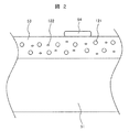
図2は、本発明のガス絶縁開閉装置のタンクの一部を示す模式断面図である。
FIG. 2 is a schematic cross-sectional view showing a part of the tank of the gas insulated switchgear of the present invention.
本図に示すように、タンク壁51の内面には、樹脂層53が設けられている。樹脂層53は、エポキシ樹脂等に非線形抵抗材121、122を添加し混合したものをコーティングすることにより形成したものである。非線形抵抗材121、122としては、酸化亜鉛(ZnO)、炭化ケイ素(SiC)、チタン酸バリウム(BaTiO3)、ダイヤモンドなどが用いられる。
As shown in the figure, a resin layer 53 is provided on the inner surface of the tank wall 51. The resin layer 53 is formed by coating a mixture of epoxy resin or the like with the nonlinear resistance materials 121 and 122 added and mixed. As the nonlinear resistance materials 121 and 122, zinc oxide (ZnO), silicon carbide (SiC), barium titanate (BaTiO 3 ), diamond or the like is used.
すなわち、本発明においては、非線形抵抗材121、122は、粒子状であり、異なる組成の二種類以上で構成されている。
That is, in the present invention, the nonlinear resistance materials 121 and 122 are in the form of particles and are composed of two or more kinds having different compositions.
なお、タンク壁51の内面には、異物54(金属異物)が付着する場合がある。
Note that foreign matter 54 (metal foreign matter) may adhere to the inner surface of the tank wall 51.
図3は、図2の樹脂層53の配置の例を示す断面図である。
FIG. 3 is a cross-sectional view showing an example of the arrangement of the resin layer 53 of FIG.
本図においては、タンク壁51の内面のうち下半分の領域に樹脂層53が設けられている。タンク壁51の内面のうち上半分の領域には、非線形抵抗材を含まない樹脂(エポキシ樹脂等)が塗布され、樹脂層131(絶縁樹脂層)が形成されている。金属異物は、重力により下方に落下する場合が多いため、樹脂層53は、下半分の領域に設ければ十分である場合が多い。また、このように樹脂層53を部分的に設けることにより、製造コストを抑えることができる。
In this figure, the resin layer 53 is provided in the lower half region of the inner surface of the tank wall 51. A resin (epoxy resin or the like) containing no nonlinear resistance material is applied to the upper half region of the inner surface of the tank wall 51 to form a resin layer 131 (insulating resin layer). Since the foreign metal particles often fall downward due to gravity, it is often sufficient to provide the resin layer 53 in the lower half region. Further, by partially providing the resin layer 53 in this manner, the manufacturing cost can be suppressed.
もちろん、樹脂層53は、タンク壁51の内面のうち上半分の領域にも設けてもよい。
場合によっては、下半分の全領域と上半分の領域の一部とに樹脂層53を設けてもよい。
樹脂層53は、少なくとも下半分の全領域に設けることが望ましい。 Of course, theresin layer 53 may also be provided in the upper half region of the inner surface of the tank wall 51.
In some cases, theresin layer 53 may be provided in the entire area of the lower half and a part of the area of the upper half.
It is desirable that theresin layer 53 be provided in at least the entire lower half region.
場合によっては、下半分の全領域と上半分の領域の一部とに樹脂層53を設けてもよい。
樹脂層53は、少なくとも下半分の全領域に設けることが望ましい。 Of course, the
In some cases, the
It is desirable that the
つぎに、非線形抵抗材121、122を含む樹脂層53の作用効果について、図2を用いて説明する。
Next, the function and effect of the resin layer 53 including the nonlinear resistance materials 121 and 122 will be described with reference to FIG.
タンクの内部に異物54(金属異物)が発生した場合、異物54の近傍に電界が集中し、高電界となる。この範囲にある非線形抵抗材121、122への電界が上昇すると、非線形抵抗材121、122の導電率が大きくなり、電気的に異物54の先端部の大きさが拡がることと等価となり、異物54近傍の電界集中が緩和される。この緩和により、異物54付着時の絶縁耐力が向上する。
When foreign matter 54 (metal foreign matter) occurs inside the tank, the electric field is concentrated near the foreign matter 54 and becomes a high electric field. When the electric field to the nonlinear resistance materials 121 and 122 in this range rises, the electrical conductivity of the nonlinear resistance materials 121 and 122 increases, which is equivalent to electrically expanding the size of the tip of the foreign matter 54, and the foreign matter 54. Electric field concentration in the vicinity is reduced. This relaxation improves the dielectric strength when the foreign matter 54 is attached.
なお、樹脂層53の厚さは、50μm以上が好適である。また、樹脂層53の厚さは、タンク内の寸法、材料コスト等の面から、1mm以下が望ましく、200μm以下が更に望ましい。
The thickness of the resin layer 53 is preferably 50 μm or more. In addition, the thickness of the resin layer 53 is preferably 1 mm or less, more preferably 200 μm or less from the viewpoints of the dimensions in the tank, material costs, and the like.
以下、実施例について説明する。
Below, examples will be explained.
図4は、非線形抵抗材の一例である酸化亜鉛の電界-導電率特性を示すグラフである。
横軸に電界、縦軸に導電率をとっている。樹脂層における酸化亜鉛の濃度は、10質量%である。 FIG. 4 is a graph showing electric field-conductivity characteristics of zinc oxide, which is an example of a nonlinear resistance material.
The horizontal axis represents the electric field and the vertical axis represents the conductivity. The concentration of zinc oxide in the resin layer is 10% by mass.
本図に示すように、酸化亜鉛は、非線形の電界-導電率特性(非線形特性)を有する。
酸化亜鉛の場合、電界-導電率曲線の急峻な上昇が開始する電界(以下「動作電界」という。)は、約7kV/mmである。すなわち、酸化亜鉛の場合、電界が約7kV/mmになると、非線形特性曲線(以下、単に「曲線」ともいう。)の傾きが急になり、曲線が立ち上がり、導電率が急上昇する。 As shown in this figure, zinc oxide has a non-linear electric field-conductivity characteristic (non-linear characteristic).
In the case of zinc oxide, the electric field at which the steep rise of the electric field-conductivity curve starts (hereinafter referred to as “operating electric field”) is about 7 kV/mm. That is, in the case of zinc oxide, when the electric field is about 7 kV/mm, the slope of the nonlinear characteristic curve (hereinafter, also simply referred to as “curve”) becomes steep, the curve rises, and the conductivity sharply rises.
なお、「動作電界」の更に厳密な定義の一例としては、曲線の傾きの変化率(二次導関数)が所定の値以上に大きくなり始める電界の値としてもよい。この場合に、曲線の近似式を3次以上のTaylor多項式で表し、二次導関数を算出することにより、動作電界を算出することができる。
Note that, as an example of a more rigorous definition of the "operating electric field", the value of the electric field at which the rate of change (second derivative) of the slope of the curve starts to increase above a predetermined value may be used. In this case, the operating electric field can be calculated by expressing the approximate expression of the curve with a Taylor polynomial of third or higher order and calculating the second derivative.
動作電界は、非線形抵抗材の種類だけでなく、樹脂中の非線形抵抗材の濃度によっても変化する。このため、異なる種類の非線形抵抗材について動作電界を比較する場合は、本明細書においては、質量基準で同じ濃度でかつ同じ樹脂と混合したもの同士で測定された非線形特性曲線を比較対象とする。よって、第一の非線形抵抗材は、第二の非線形抵抗材よりも、動作電界が高く、かつ、動作電界より高い電界の範囲で非線形特性曲線の傾きが大きい、といった表現が可能である。
The operating electric field changes not only with the type of nonlinear resistance material, but also with the concentration of the nonlinear resistance material in the resin. Therefore, when comparing operating electric fields for different types of non-linear resistance materials, in the present specification, non-linear characteristic curves measured at the same concentration on the mass basis and mixed with the same resin will be compared. .. Therefore, it can be expressed that the first nonlinear resistance material has a higher operating electric field than the second nonlinear resistance material, and that the slope of the nonlinear characteristic curve is large in the range of the electric field higher than the operating electric field.
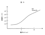
図5は、非線形抵抗材である炭化ケイ素の電界-導電率特性を示すグラフである。樹脂層における炭化ケイ素の濃度は、10質量%である。
FIG. 5 is a graph showing electric field-conductivity characteristics of silicon carbide, which is a nonlinear resistance material. The concentration of silicon carbide in the resin layer is 10% by mass.
本図に示すように、炭化ケイ素の場合、動作電界が低く、曲線の傾きが比較的緩やかである。曲線の立ち上がり(動作電界)は、約4kV/mmであり、約8kV/mm以上では曲線の傾きが緩やかになる。
As shown in this figure, in the case of silicon carbide, the operating electric field is low and the slope of the curve is relatively gentle. The rise of the curve (operating electric field) is about 4 kV/mm, and the slope of the curve becomes gentle at about 8 kV/mm or more.
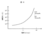
図6は、二種類の非線形抵抗材を混合した場合の電界-導電率特性を示すグラフである。樹脂層における酸化亜鉛の濃度は10質量%であり、炭化ケイ素の濃度は10質量%である。
FIG. 6 is a graph showing electric field-conductivity characteristics when two types of nonlinear resistance materials are mixed. The zinc oxide concentration in the resin layer is 10% by mass, and the silicon carbide concentration is 10% by mass.
本図においては、動作電界が低い炭化ケイ素の作用により、約4kV/mmで曲線の傾きが大きくなり始め、約7kV/mm以上で更に傾きが大きくなっている。
In this figure, due to the action of silicon carbide, which has a low operating electric field, the slope of the curve starts to increase at about 4 kV/mm, and further increases at about 7 kV/mm or more.
これにより、印加電圧が低い状態から異物周辺の電界が緩和される。また、高電圧において十分な電界緩和効果が得られる。動作電界が低くなるため、電界緩和のばらつきが小さくなり、低電圧での異物浮上を防止できる。また、非線形特性曲線の傾きが大きくなるため、高電圧での電界緩和効果が大きくなり、部分放電を防止でき、異物の浮上電界を高くすることが可能となる。
↑ This relaxes the electric field around the foreign matter even when the applied voltage is low. Further, a sufficient electric field relaxation effect can be obtained at high voltage. Since the operating electric field is lowered, the variation in electric field relaxation is reduced, and the floating of foreign matter at a low voltage can be prevented. Further, since the slope of the non-linear characteristic curve becomes large, the electric field relaxation effect at a high voltage becomes large, partial discharge can be prevented, and the floating electric field of foreign matter can be increased.
非線形抵抗材を含む樹脂(コーティング材)のタンク壁51の内面への塗布は、スプレーコーティング若しくは刷毛塗りによりなされる。
The resin (coating material) containing the nonlinear resistance material is applied to the inner surface of the tank wall 51 by spray coating or brush coating.
まとめると、図4及び5から、第一の非線形抵抗材である酸化亜鉛は、第二の非線形抵抗材である炭化ケイ素よりも、動作電界が高く、かつ、動作電界より高い電界の範囲で非線形特性曲線の傾きが大きい、と言える。そして、図6の曲線は、図4及び5の曲線を重ね合わせた形状を有する。このため、適切な導電率及び動作電界が得られる。
In summary, from FIGS. 4 and 5, the first non-linear resistance material, zinc oxide, has a higher operating electric field than the second non-linear resistance material, silicon carbide, and is non-linear in the electric field range higher than the operating electric field. It can be said that the slope of the characteristic curve is large. The curve of FIG. 6 has a shape in which the curves of FIGS. 4 and 5 are superposed. Therefore, an appropriate conductivity and operating electric field can be obtained.
本実施例の樹脂層の動作電界は、3kV/mm以上であることが望ましい。動作電界が低すぎると、樹脂層の絶縁機能が不十分となるからである。また、本実施例の樹脂層の動作電界は、5kV/mm以下であることが望ましい。樹脂層の動作電界は、第二の非線形抵抗材の動作電界の望ましい範囲に対応している。
The operating electric field of the resin layer of this example is preferably 3 kV/mm or more. This is because if the operating electric field is too low, the insulating function of the resin layer will be insufficient. The operating electric field of the resin layer of this example is preferably 5 kV/mm or less. The operating electric field of the resin layer corresponds to the desired range of the operating electric field of the second nonlinear resistance material.
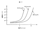
図7は、非線形抵抗材の添加量をパラメータとした場合の電界-導電率特性を示すグラフである。
FIG. 7 is a graph showing electric field-conductivity characteristics when the additive amount of the nonlinear resistance material is used as a parameter.
本図においては、樹脂層における酸化亜鉛及び炭化ケイ素の濃度が等しくなるように添加したものであり、それぞれの濃度が、5質量%、10質量%、15質量%の場合を示している。すなわち、酸化亜鉛の濃度が5質量%でかつ炭化ケイ素の濃度が5質量%の場合(各5質量%)、酸化亜鉛の濃度が10質量%でかつ炭化ケイ素の濃度が10質量%の場合(各10質量%)、酸化亜鉛の濃度が15質量%でかつ炭化ケイ素の濃度が15質量%の場合(各15質量%)である。
In this figure, zinc oxide and silicon carbide are added to the resin layer so as to have equal concentrations, and the respective concentrations are 5% by mass, 10% by mass, and 15% by mass. That is, when the concentration of zinc oxide is 5% by mass and the concentration of silicon carbide is 5% by mass (each 5% by mass), the concentration of zinc oxide is 10% by mass and the concentration of silicon carbide is 10% by mass ( 10% by mass), the concentration of zinc oxide is 15% by mass, and the concentration of silicon carbide is 15% by mass (15% by mass each).
本図に示すように、コーティング材の電界-導電率特性は、非線形抵抗材の添加量により変化する。具体的には、曲線の立ち上がりの始まり(動作電界)が、各5質量%では約7kV/mm、各10質量%では約5kV/mm、各15質量%の場合では約4kV/mmである。
As shown in this figure, the electric field-conductivity characteristics of the coating material change depending on the addition amount of the nonlinear resistance material. Specifically, the start of the rising of the curve (operating electric field) is about 7 kV/mm for each 5 mass %, about 5 kV/mm for each 10 mass %, and about 4 kV/mm for each 15 mass %.
よって、非線形抵抗材の添加量が少ない場合、異物がタンク壁の内面に存在する場合において、電界集中時の導電率上昇が不十分となり、電界緩和に至らない可能性がある。
Therefore, if the amount of addition of the nonlinear resistance material is small, the increase in conductivity during electric field concentration may be insufficient when foreign matter is present on the inner surface of the tank wall, and electric field relaxation may not occur.
上記課題を解決するために、複数種類の非線形抵抗材の添加量の合計は、5質量%から50質量%までの範囲が電界緩和効果、電界-導電率特性、及び塗布作業におけるコーティング材の粘度において好適である。非線形抵抗材の添加量としては、5質量%から20質量%までの範囲が更に好適であり、5質量%から15質量%までの範囲が特に好適である。
In order to solve the above problems, the total addition amount of a plurality of types of non-linear resistance materials is in the range of 5% by mass to 50% by mass, the electric field relaxation effect, the electric field-conductivity characteristic, and the viscosity of the coating material in the coating operation. Is preferred. The addition amount of the nonlinear resistance material is more preferably in the range of 5% by mass to 20% by mass, and particularly preferably in the range of 5% by mass to 15% by mass.
また、動作電界の低い非線形抵抗材(例えば炭化ケイ素)と動作電界の高い非線形抵抗材(例えば酸化亜鉛)との混合率は、1:4から4:1までの間とすることで所望の非線形特性となり、異物の周囲における電界緩和効果が生じ、好適である。この混合率は、1:3から3:1までの間が更に好適であり、1:2から2:1までの間が特に好適である。
Further, the mixing ratio of the non-linear resistance material having a low operating electric field (eg, silicon carbide) and the non-linear resistance material having a high operating electric field (eg, zinc oxide) is between 1:4 and 4:1. It is preferable because it has characteristics and an electric field relaxation effect occurs around the foreign matter. This mixing ratio is more preferably 1:3 to 3:1, and particularly preferably 1:2 to 2:1.
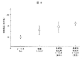
図8は、金属異物をタンク内に設置した場合における浮上試験の結果を示すグラフである。縦軸は、破壊電圧の相対値をとっている。ここで、破壊電圧とは、所定の条件において金属異物が浮上する電圧をいう。この電圧は、金属異物浮上電圧ともいう。
FIG. 8 is a graph showing the result of the levitation test when the metallic foreign matter is installed in the tank. The vertical axis represents the relative value of the breakdown voltage. Here, the breakdown voltage means a voltage at which the metallic foreign matter floats up under a predetermined condition. This voltage is also called a metal foreign matter levitating voltage.
本図においては、タンク壁の内面を金属面とした場合(コーティングなし)の異物の浮上電界の値を1.0としている。樹脂のみによる絶縁膜で被覆した場合(樹脂コーティング)、浮上電界は平均値が1.3程度となり、ばらつきは20%程度となる。
In this figure, the value of the floating electric field of foreign matter when the inner surface of the tank wall is a metal surface (without coating) is set to 1.0. When coated with an insulating film made of only resin (resin coating), the floating electric field has an average value of about 1.3 and a variation of about 20%.
また、酸化亜鉛単体を添加したコーティング材を塗布した場合(非線形抵抗材コーティング(単体))、平均値は1.5程度と高くなるが、ばらつきは20%程度と樹脂コーティングと同等である。
When a coating material containing zinc oxide alone is applied (non-linear resistance material coating (single body)), the average value increases to about 1.5, but the variation is about 20%, which is equivalent to resin coating.
これに対して、本実施例である、二種類の非線形抵抗材(酸化亜鉛及び炭化ケイ素)を添加したコーティング材を塗布した場合(非線形抵抗材コーティング(混合))、浮上電界の平均値が1.6以上となり、かつ、ばらつきが5%程度と小さくなる。これは、ばらつきが小さくなった分、平均値が高くなり、低い電圧では金属異物の浮上が生じなくなったことを意味する。これにより、タンク内部に金属異物が存在する場合においても、金属異物の浮上を制限し、高い絶縁耐力を維持することができる。
On the other hand, when the coating material containing two types of non-linear resistance materials (zinc oxide and silicon carbide) according to the present embodiment is applied (non-linear resistance material coating (mixing)), the average value of the levitation electric field is 1 6 or more, and the variation is as small as about 5%. This means that the smaller the variation is, the higher the average value is, and the floating of the metallic foreign matter does not occur at a low voltage. As a result, even if the metallic foreign matter is present inside the tank, the floating of the metallic foreign matter can be restricted and a high dielectric strength can be maintained.
なお、二種類の非線形抵抗材を一種類ずつに分けてコーティング材を作製し、タンクの内面に塗布することにより、二層の樹脂層を重ねた構成とした場合、金属異物と接触する非線形抵抗材の特性に強く影響されるため、本実施例のような効果を得ることはできない。
When two types of non-linear resistance materials are divided into one type and a coating material is applied and applied to the inner surface of the tank, and two resin layers are stacked, the non-linear resistance that contacts metal foreign matter Since it is strongly influenced by the characteristics of the material, the effect of this embodiment cannot be obtained.
図9は、本発明の樹脂層の形成工程の一例を示すフロー図である。
FIG. 9 is a flow chart showing an example of the resin layer forming process of the present invention.
本図に示すように、まず、表面処理剤と非線形抵抗材を混合する(S101)。この混合物を樹脂に添加する(S102)。これを撹拌する(S103)。これにより、非線形抵抗材の凝集が防止され、非線形抵抗材が一様に分散されたコーティング材となる。なお、表面処理剤の一例としては、シラン系カップリング剤がある。また、工程S102又はS103において、樹脂の硬化剤も混合する。
First, as shown in the figure, the surface treatment agent and the non-linear resistance material are mixed (S101). This mixture is added to the resin (S102). This is stirred (S103). As a result, the non-linear resistance material is prevented from agglomerating, and the non-linear resistance material is uniformly dispersed in the coating material. A silane coupling agent is an example of the surface treatment agent. Further, in step S102 or S103, a resin curing agent is also mixed.
撹拌後のコーティング材をスプレーガンによりタンク壁の内面に塗布する(S104)。塗布されたコーティング材は、所定の条件にて硬化される(S105)。
Apply the coating material after stirring to the inner surface of the tank wall with a spray gun (S104). The applied coating material is cured under predetermined conditions (S105).
工程S101において表面処理剤を用いることにより、工程S103の撹拌後、非線形抵抗材が樹脂中に一様に分散される。このため、コーティング材を塗布した範囲においては、金属異物の周囲における電界緩和効果が有効となる。これにより、金属異物の浮上電界向上効果が安定する。表面処理剤の添加量は、0.1質量%から5質量%までの範囲が好適である。
By using the surface treatment agent in step S101, the nonlinear resistance material is uniformly dispersed in the resin after the stirring in step S103. Therefore, in the range where the coating material is applied, the electric field relaxation effect around the metallic foreign matter is effective. As a result, the effect of improving the floating electric field of the metallic foreign matter is stabilized. The addition amount of the surface treatment agent is preferably in the range of 0.1% by mass to 5% by mass.
上記のコーティング材は、非線形抵抗材を含まない絶縁樹脂単体をタンク内面に下塗りとして塗布した後、その塗布面に塗布してもよい。この場合、絶縁樹脂単体の下塗りをした後、一旦硬化し、その後、その塗布面にコーティング材を塗布することが望ましい。これにより、下塗りにより形成された絶縁樹脂層により、タンクから異物への電荷のチャージが妨げられるとともに、非線形抵抗材を含む樹脂層により、電界集中の緩和及び部分放電の抑制が可能となる。
The above coating material may be applied as an undercoat on the inner surface of the tank by using an insulating resin alone that does not contain the non-linear resistance material, and then on the applied surface. In this case, it is desirable to undercoat the insulating resin alone, then cure it once, and then apply the coating material to the application surface. As a result, the insulating resin layer formed by the undercoat prevents the charge from being charged from the tank to the foreign matter, and the resin layer containing the non-linear resistance material can alleviate the electric field concentration and suppress the partial discharge.
絶縁樹脂層の厚さは、30μm以上が好適である。また、非線形抵抗材を含む樹脂層(コーティング層)の厚さは、50μm以上が好適である。これらの層の厚さは、タンク内の寸法、材料コスト等の面から、それぞれ、1mm以下が望ましく、200μm以下が更に望ましい。この上限値は、コーティング層のみの場合も同様である。
-The thickness of the insulating resin layer is preferably 30 μm or more. The thickness of the resin layer (coating layer) containing the nonlinear resistance material is preferably 50 μm or more. The thickness of each of these layers is preferably 1 mm or less, more preferably 200 μm or less, from the viewpoints of the dimensions in the tank, material costs, and the like. This upper limit is the same for the coating layer alone.
1:高電圧導体、2:接地タンク、20:遮断器、21:断路器、22:接地開閉器、23:変流器、24:変圧器、25、26:母線、30:絶縁スペーサ、51:タンク壁、53:樹脂層、54:異物、100:ガス絶縁開閉装置、121、122:非線形抵抗材、131:樹脂層。
1: high-voltage conductor, 2: ground tank, 20: circuit breaker, 21: disconnector, 22: ground switch, 23: current transformer, 24: transformer, 25, 26: busbar, 30: insulating spacer, 51 : Tank wall, 53: resin layer, 54: foreign matter, 100: gas insulated switchgear, 121, 122: non-linear resistance material, 131: resin layer.
Claims (26)
- 接地されているタンクと、
前記タンクの内部に設置され前記タンクとは絶縁されている高電圧導体と、を有し、
前記タンクの内面には、樹脂に複数種類の非線形抵抗材が混合された構成を有する樹脂層が形成され、
前記複数種類の非線形抵抗材のうち少なくとも一種類の非線形抵抗材である第一の非線形抵抗材は、前記複数種類の非線形抵抗材のうち少なくとも一種類の他の非線形抵抗材である第二の非線形抵抗材よりも、動作電界が高く、かつ、前記動作電界より高い電界の範囲で非線形特性曲線の傾きが大きい、ガス絶縁開閉装置。 A grounded tank,
A high-voltage conductor installed inside the tank and insulated from the tank,
On the inner surface of the tank, a resin layer having a configuration in which a plurality of types of nonlinear resistance materials are mixed with resin is formed,
The first non-linear resistance material, which is at least one non-linear resistance material of the plurality of non-linear resistance materials, is the second non-linear resistance material, which is at least one other non-linear resistance material of the plurality of non-linear resistance materials. A gas-insulated switchgear having an operating electric field higher than that of the resistance material and having a large non-linear characteristic curve inclination in a range of an electric field higher than the operating electric field. - 前記複数種類の非線形抵抗材の添加量の合計は、5質量%から50質量%までの範囲にある、請求項1記載のガス絶縁開閉装置。 The gas-insulated switchgear according to claim 1, wherein the total amount of addition of the plurality of types of nonlinear resistance materials is in the range of 5% by mass to 50% by mass.
- 前記第一の非線形抵抗材と前記第二の非線形抵抗材との混合率は、1:4から4:1までの範囲にある、請求項2記載のガス絶縁開閉装置。 The gas-insulated switchgear according to claim 2, wherein the mixing ratio of the first nonlinear resistance material and the second nonlinear resistance material is in the range of 1:4 to 4:1.
- 前記樹脂層は、表面処理剤を含む、請求項1記載のガス絶縁開閉装置。 The gas-insulated switchgear according to claim 1, wherein the resin layer contains a surface treatment agent.
- 前記表面処理剤の添加量は、0.1質量%から5質量%までの範囲にある、請求項4記載のガス絶縁開閉装置。 The gas-insulated switchgear according to claim 4, wherein the amount of the surface treatment agent added is in the range of 0.1% by mass to 5% by mass.
- 前記樹脂層の厚さは、50μm以上1mm以下である、請求項1記載のガス絶縁開閉装置。 The gas-insulated switchgear according to claim 1, wherein the resin layer has a thickness of 50 μm or more and 1 mm or less.
- 前記タンクの前記内面と前記樹脂層との間には、前記非線形抵抗材を含まない絶縁樹脂層が設けられている、請求項1記載のガス絶縁開閉装置。 The gas-insulated switchgear according to claim 1, wherein an insulating resin layer not containing the nonlinear resistance material is provided between the inner surface of the tank and the resin layer.
- 前記絶縁樹脂層の厚さは、30μm以上1mm以下である、請求項7記載のガス絶縁開閉装置。 The gas-insulated switchgear according to claim 7, wherein the insulating resin layer has a thickness of 30 μm or more and 1 mm or less.
- 前記樹脂層の厚さは、50μm以上1mm以下である、請求項8記載のガス絶縁開閉装置。 The gas-insulated switchgear according to claim 8, wherein the resin layer has a thickness of 50 μm or more and 1 mm or less.
- 前記非線形抵抗材は、酸化亜鉛、炭化ケイ素、チタン酸バリウム及びダイヤモンドからなる群から選択される二種類以上である、請求項1記載のガス絶縁開閉装置。 The gas insulated switchgear according to claim 1, wherein the non-linear resistance material is at least two kinds selected from the group consisting of zinc oxide, silicon carbide, barium titanate and diamond.
- 前記第一の非線形抵抗材は、酸化亜鉛であり、
前記第二の非線形抵抗材は、炭化ケイ素である、請求項1記載のガス絶縁開閉装置。 The first nonlinear resistance material is zinc oxide,
The gas insulated switchgear according to claim 1, wherein the second non-linear resistance material is silicon carbide. - 前記第二の非線形抵抗材の前記動作電界は、3kV/mm以上5kV/mm以下である、請求項1記載のガス絶縁開閉装置。 The gas insulated switchgear according to claim 1, wherein the operating electric field of the second nonlinear resistance material is 3 kV/mm or more and 5 kV/mm or less.
- 前記樹脂層は、前記タンクの前記内面のうち、少なくとも下半分の領域に形成されている、請求項1記載のガス絶縁開閉装置。 The gas-insulated switchgear according to claim 1, wherein the resin layer is formed in at least a lower half region of the inner surface of the tank.
- 接地されているタンクと、
前記タンクの内部に設置され前記タンクとは絶縁されている高電圧導体と、を有し、
前記タンクの内面には、樹脂に複数種類の非線形抵抗材が混合された構成を有する樹脂層が形成され、
前記複数種類の非線形抵抗材のうち少なくとも一種類の非線形抵抗材である第一の非線形抵抗材は、前記複数種類の非線形抵抗材のうち少なくとも一種類の他の非線形抵抗材である第二の非線形抵抗材よりも、動作電界が高く、かつ、前記動作電界より高い電界の範囲で非線形特性曲線の傾きが大きい、ガス絶縁開閉装置を製造する方法であって、
前記樹脂及び前記複数種類の非線形抵抗材を混合してコーティング材を作製する工程と、
前記コーティング材を前記タンクの前記内面に塗布する工程と、
前記コーティング材を硬化して前記樹脂層を形成する工程と、を含む、ガス絶縁開閉装置の製造方法。 A grounded tank,
A high-voltage conductor installed inside the tank and insulated from the tank,
On the inner surface of the tank, a resin layer having a configuration in which a plurality of types of nonlinear resistance materials are mixed with resin is formed,
The first non-linear resistance material, which is at least one non-linear resistance material of the plurality of non-linear resistance materials, is the second non-linear resistance material, which is at least one other non-linear resistance material of the plurality of non-linear resistance materials. A method of manufacturing a gas-insulated switchgear having a higher operating electric field than a resistance material, and having a large slope of a non-linear characteristic curve in a range of an electric field higher than the operating electric field,
A step of preparing a coating material by mixing the resin and the plurality of types of non-linear resistance materials,
Applying the coating material to the inner surface of the tank,
And a step of curing the coating material to form the resin layer. - 前記複数種類の非線形抵抗材の添加量の合計は、5質量%から50質量%までの範囲にある、請求項14記載のガス絶縁開閉装置の製造方法。 The method for manufacturing a gas insulated switchgear according to claim 14, wherein the total amount of addition of the plurality of types of nonlinear resistance materials is in the range of 5% by mass to 50% by mass.
- 前記第一の非線形抵抗材と前記第二の非線形抵抗材との混合率は、1:4から4:1までの範囲にある、請求項15記載のガス絶縁開閉装置の製造方法。 The method for manufacturing a gas insulated switchgear according to claim 15, wherein a mixing ratio of the first nonlinear resistance material and the second nonlinear resistance material is in the range of 1:4 to 4:1.
- 前記複数種類の非線形抵抗材に表面処理剤を混合し、その後、更に前記樹脂と混合して前記コーティング材を作製する、請求項14記載のガス絶縁開閉装置の製造方法。 15. The method for manufacturing a gas insulated switchgear according to claim 14, wherein a surface treatment agent is mixed with the plurality of types of nonlinear resistance materials, and then the coating material is prepared by further mixing with the resin.
- 前記表面処理剤の添加量は、0.1質量%から5質量%までの範囲にある、請求項17記載のガス絶縁開閉装置の製造方法。 The method for manufacturing a gas insulated switchgear according to claim 17, wherein the amount of the surface treatment agent added is in the range of 0.1% by mass to 5% by mass.
- 前記樹脂層の厚さは、50μm以上1mm以下である、請求項14記載のガス絶縁開閉装置の製造方法。 The method for manufacturing a gas insulated switchgear according to claim 14, wherein the thickness of the resin layer is 50 μm or more and 1 mm or less.
- 前記タンクの前記内面に前記非線形抵抗材を含まない絶縁樹脂単体を塗布して絶縁樹脂層を形成し、その後、前記絶縁樹脂層の表面に前記コーティング材を塗布する、請求項14記載のガス絶縁開閉装置の製造方法。 15. The gas insulation according to claim 14, wherein an insulating resin simple substance not containing the non-linear resistance material is applied to the inner surface of the tank to form an insulating resin layer, and then the coating material is applied to the surface of the insulating resin layer. Switchgear manufacturing method.
- 前記絶縁樹脂層の厚さは、30μm以上1mm以下である、請求項20記載のガス絶縁開閉装置の製造方法。 The method for manufacturing a gas insulated switchgear according to claim 20, wherein the insulating resin layer has a thickness of 30 μm or more and 1 mm or less.
- 前記樹脂層の厚さは、50μm以上1mm以下である、請求項21記載のガス絶縁開閉装置の製造方法。 The method for manufacturing a gas insulated switchgear according to claim 21, wherein the resin layer has a thickness of 50 μm or more and 1 mm or less.
- 前記非線形抵抗材は、酸化亜鉛、炭化ケイ素、チタン酸バリウム及びダイヤモンドからなる群から選択される二種類以上である、請求項14記載のガス絶縁開閉装置の製造方法。 The method for manufacturing a gas insulated switchgear according to claim 14, wherein the non-linear resistance material is at least two kinds selected from the group consisting of zinc oxide, silicon carbide, barium titanate and diamond.
- 前記第一の非線形抵抗材は、酸化亜鉛であり、
前記第二の非線形抵抗材は、炭化ケイ素である、請求項14記載のガス絶縁開閉装置の製造方法。 The first nonlinear resistance material is zinc oxide,
The method for manufacturing a gas insulated switchgear according to claim 14, wherein the second nonlinear resistance material is silicon carbide. - 前記第二の非線形抵抗材の前記動作電界は、3kV/mm以上5kV/mm以下である、請求項14記載のガス絶縁開閉装置の製造方法。 The method for manufacturing a gas insulated switchgear according to claim 14, wherein the operating electric field of the second non-linear resistance material is 3 kV/mm or more and 5 kV/mm or less.
- 前記樹脂層は、前記タンクの前記内面のうち、少なくとも下半分の領域に形成する、請求項14記載のガス絶縁開閉装置の製造方法。 The method for manufacturing a gas insulated switchgear according to claim 14, wherein the resin layer is formed in at least a lower half region of the inner surface of the tank.
Applications Claiming Priority (2)
| Application Number | Priority Date | Filing Date | Title |
|---|---|---|---|
| JP2019-008385 | 2019-01-22 | ||
| JP2019008385A JP7137486B2 (en) | 2019-01-22 | 2019-01-22 | Gas-insulated switchgear and manufacturing method thereof |
Publications (1)
| Publication Number | Publication Date |
|---|---|
| WO2020152952A1 true WO2020152952A1 (en) | 2020-07-30 |
Family
ID=71736132
Family Applications (1)
| Application Number | Title | Priority Date | Filing Date |
|---|---|---|---|
| PCT/JP2019/044297 WO2020152952A1 (en) | 2019-01-22 | 2019-11-12 | Gas insulated switchgear and manufacturing method thereof |
Country Status (2)
| Country | Link |
|---|---|
| JP (1) | JP7137486B2 (en) |
| WO (1) | WO2020152952A1 (en) |
Citations (3)
| Publication number | Priority date | Publication date | Assignee | Title |
|---|---|---|---|---|
| JP2014156587A (en) * | 2013-01-18 | 2014-08-28 | Toshiba Corp | Nonlinear resistive coating material, bus bar and stator coil |
| WO2015136753A1 (en) * | 2014-03-12 | 2015-09-17 | 三菱電機株式会社 | Gas insulated switch device |
| JP2018196280A (en) * | 2017-05-19 | 2018-12-06 | 株式会社日立製作所 | Insulation spacer and gas insulation opening/closing device using the same |
-
2019
- 2019-01-22 JP JP2019008385A patent/JP7137486B2/en active Active
- 2019-11-12 WO PCT/JP2019/044297 patent/WO2020152952A1/en active Application Filing
Patent Citations (3)
| Publication number | Priority date | Publication date | Assignee | Title |
|---|---|---|---|---|
| JP2014156587A (en) * | 2013-01-18 | 2014-08-28 | Toshiba Corp | Nonlinear resistive coating material, bus bar and stator coil |
| WO2015136753A1 (en) * | 2014-03-12 | 2015-09-17 | 三菱電機株式会社 | Gas insulated switch device |
| JP2018196280A (en) * | 2017-05-19 | 2018-12-06 | 株式会社日立製作所 | Insulation spacer and gas insulation opening/closing device using the same |
Also Published As
| Publication number | Publication date |
|---|---|
| JP7137486B2 (en) | 2022-09-14 |
| JP2020120463A (en) | 2020-08-06 |
Similar Documents
| Publication | Publication Date | Title |
|---|---|---|
| US7262367B2 (en) | High voltage bushing with field control material | |
| JP5705384B1 (en) | Gas insulation equipment | |
| EP2937958B1 (en) | Gas insulated electric equipment | |
| JP5710080B2 (en) | Gas insulated switchgear | |
| EP3098919B1 (en) | Gas-insulated electric apparatus | |
| WO2020152952A1 (en) | Gas insulated switchgear and manufacturing method thereof | |
| JP6352782B2 (en) | Insulating spacer | |
| JP6807276B2 (en) | Insulation spacer and gas insulation switchgear using it | |
| JP2004335390A (en) | Cone type insulation spacer | |
| US20190372318A1 (en) | Gas-insulated electrical equipment | |
| JP3897972B2 (en) | Cable termination connection structure for electrical equipment | |
| WO2019123889A1 (en) | Open/close device | |
| WO2017098553A1 (en) | Gas insulation apparatus | |
| JP7418672B1 (en) | insulation equipment | |
| JP7278997B2 (en) | gas insulated switchgear | |
| JP7400113B2 (en) | gas insulated equipment | |
| JPS6023569B2 (en) | gas insulated electrical equipment | |
| JPH0345111A (en) | Gas-insulated machine | |
| UA127036C2 (en) | POLYMER INSULATOR (OPTIONS) | |
| JP2006320196A (en) | Cable termination and connection structure | |
| US1715889A (en) | Insulator | |
| WO2019093071A1 (en) | Gas insulated switchgear | |
| UA139361U (en) | POLYMER INSULATOR | |
| JP5395038B2 (en) | Gas insulated electrical equipment | |
| UA141542U (en) | POLYMER INSULATOR |
Legal Events
| Date | Code | Title | Description |
|---|---|---|---|
| 121 | Ep: the epo has been informed by wipo that ep was designated in this application |
Ref document number: 19911325 Country of ref document: EP Kind code of ref document: A1 |
|
| NENP | Non-entry into the national phase |
Ref country code: DE |
|
| 122 | Ep: pct application non-entry in european phase |
Ref document number: 19911325 Country of ref document: EP Kind code of ref document: A1 |