WO2020152889A1 - 装置診断装置、プラズマ処理装置及び装置診断方法 - Google Patents
装置診断装置、プラズマ処理装置及び装置診断方法 Download PDFInfo
- Publication number
- WO2020152889A1 WO2020152889A1 PCT/JP2019/029762 JP2019029762W WO2020152889A1 WO 2020152889 A1 WO2020152889 A1 WO 2020152889A1 JP 2019029762 W JP2019029762 W JP 2019029762W WO 2020152889 A1 WO2020152889 A1 WO 2020152889A1
- Authority
- WO
- WIPO (PCT)
- Prior art keywords
- plasma processing
- probability distribution
- sensor
- processing apparatus
- diagnostic
- Prior art date
- Legal status (The legal status is an assumption and is not a legal conclusion. Google has not performed a legal analysis and makes no representation as to the accuracy of the status listed.)
- Ceased
Links
Images





Classifications
-
- H—ELECTRICITY
- H01—ELECTRIC ELEMENTS
- H01J—ELECTRIC DISCHARGE TUBES OR DISCHARGE LAMPS
- H01J37/00—Discharge tubes with provision for introducing objects or material to be exposed to the discharge, e.g. for the purpose of examination or processing thereof
- H01J37/32—Gas-filled discharge tubes
- H01J37/32917—Plasma diagnostics
- H01J37/32935—Monitoring and controlling tubes by information coming from the object and/or discharge
-
- H—ELECTRICITY
- H01—ELECTRIC ELEMENTS
- H01J—ELECTRIC DISCHARGE TUBES OR DISCHARGE LAMPS
- H01J37/00—Discharge tubes with provision for introducing objects or material to be exposed to the discharge, e.g. for the purpose of examination or processing thereof
- H01J37/32—Gas-filled discharge tubes
- H01J37/32917—Plasma diagnostics
-
- G—PHYSICS
- G01—MEASURING; TESTING
- G01M—TESTING STATIC OR DYNAMIC BALANCE OF MACHINES OR STRUCTURES; TESTING OF STRUCTURES OR APPARATUS, NOT OTHERWISE PROVIDED FOR
- G01M99/00—Subject matter not provided for in other groups of this subclass
- G01M99/005—Testing of complete machines, e.g. washing-machines or mobile phones
-
- G—PHYSICS
- G05—CONTROLLING; REGULATING
- G05B—CONTROL OR REGULATING SYSTEMS IN GENERAL; FUNCTIONAL ELEMENTS OF SUCH SYSTEMS; MONITORING OR TESTING ARRANGEMENTS FOR SUCH SYSTEMS OR ELEMENTS
- G05B23/00—Testing or monitoring of control systems or parts thereof
- G05B23/02—Electric testing or monitoring
- G05B23/0205—Electric testing or monitoring by means of a monitoring system capable of detecting and responding to faults
- G05B23/0218—Electric testing or monitoring by means of a monitoring system capable of detecting and responding to faults characterised by the fault detection method dealing with either existing or incipient faults
- G05B23/0243—Electric testing or monitoring by means of a monitoring system capable of detecting and responding to faults characterised by the fault detection method dealing with either existing or incipient faults model based detection method, e.g. first-principles knowledge model
-
- G—PHYSICS
- G06—COMPUTING OR CALCULATING; COUNTING
- G06N—COMPUTING ARRANGEMENTS BASED ON SPECIFIC COMPUTATIONAL MODELS
- G06N7/00—Computing arrangements based on specific mathematical models
- G06N7/01—Probabilistic graphical models, e.g. probabilistic networks
-
- H—ELECTRICITY
- H10—SEMICONDUCTOR DEVICES; ELECTRIC SOLID-STATE DEVICES NOT OTHERWISE PROVIDED FOR
- H10P—GENERIC PROCESSES OR APPARATUS FOR THE MANUFACTURE OR TREATMENT OF DEVICES COVERED BY CLASS H10
- H10P50/00—Etching of wafers, substrates or parts of devices
- H10P50/20—Dry etching; Plasma etching; Reactive-ion etching
- H10P50/24—Dry etching; Plasma etching; Reactive-ion etching of semiconductor materials
- H10P50/242—Dry etching; Plasma etching; Reactive-ion etching of semiconductor materials of Group IV materials
-
- H—ELECTRICITY
- H01—ELECTRIC ELEMENTS
- H01J—ELECTRIC DISCHARGE TUBES OR DISCHARGE LAMPS
- H01J2237/00—Discharge tubes exposing object to beam, e.g. for analysis treatment, etching, imaging
- H01J2237/245—Detection characterised by the variable being measured
- H01J2237/24571—Measurements of non-electric or non-magnetic variables
- H01J2237/24578—Spatial variables, e.g. position, distance
Definitions
- the present invention relates to a device diagnostic device, a plasma processing device, and a device diagnostic method.
- plasma treatment is performed to turn the substance into plasma and remove the substance on the wafer by the action of the substance.
- a device diagnosis technique is required that estimates the difference between the devices and then feeds back to the device manufacturing process and performs component deterioration diagnosis.
- Patent Document 1 As such a device diagnosis technique, for example, there is Patent Document 1.
- the anomaly detection device estimates a state in which noise is removed from the summary value by applying statistical modeling to the summary value that summarizes the observed values, and one period ahead is estimated based on the estimation. A predicted value is generated by predicting the summary value. The abnormality detection device detects whether or not there is an abnormality in the monitoring target device based on the predicted value.”
- Patent Document 1 since the probability distribution of the measurement value (sensor value) of the state sensor of the diagnosis target device is generally used for the device diagnosis, a probability distribution estimation technique is required. As described above, the plasma processing apparatuses may differ from one apparatus to another. Therefore, in the method of Patent Document 1, it is necessary to acquire a large amount of data for each apparatus in order to detect an abnormality with high accuracy.
- An object of the present invention is to estimate a probability distribution with a small amount of sensor values in a device diagnostic device.
- An apparatus diagnostic apparatus is an apparatus diagnostic apparatus for diagnosing a state of a plasma processing apparatus, and uses a first sensor value acquired by a first sensor in a first plasma processing apparatus to generate a probability distribution function.
- Prior distribution information including the previously obtained for each of the first sensor, the previously obtained prior distribution information, by the second sensor in the second plasma processing apparatus different from the first plasma processing apparatus
- An apparatus diagnostic apparatus is an apparatus diagnostic apparatus for diagnosing a state of a plasma processing apparatus, using a probability distribution function using a first sensor value acquired by a first sensor in a first plasma processing apparatus.
- Prior distribution information including the previously obtained for each of the first sensor, the previously obtained prior distribution information, and the second sensor value obtained by the second sensor in the second plasma processing apparatus and
- the probability distribution in each of the second sensors corresponding to each of the first sensors is estimated based on, and the first likelihood, which is the likelihood for the estimated probability distribution, and the likelihood for the normal distribution. Is compared with the second likelihood, and if the first likelihood is greater than the second likelihood, the state of the second plasma processing apparatus is diagnosed using the estimated probability distribution. When the second likelihood is higher than the first likelihood, the state of the second plasma processing apparatus is diagnosed using the normal distribution.
- a plasma processing apparatus is a plasma processing apparatus including a processing chamber in which a sample is plasma-processed and an apparatus diagnostic apparatus for diagnosing a state of the apparatus itself, wherein the apparatus diagnostic apparatus is a plasma processing apparatus different from the apparatus itself.
- Prior distribution information including a probability distribution function using a first sensor value obtained by the first sensor in the device is previously obtained for each of the first sensors, and the previously obtained prior distribution information, Estimating a probability distribution in each of the second sensors corresponding to each of the first sensors based on the second sensor value acquired by the second sensor in the own device, and the estimated probability distribution Is used to diagnose the state of the device itself.
- An apparatus diagnostic method is a method for diagnosing a state of a plasma processing apparatus, wherein a probability distribution function is obtained by using a first sensor value acquired by a first sensor in a first plasma processing apparatus.
- a step of diagnosing is a method for diagnosing a state of a plasma processing apparatus, wherein a probability distribution function is obtained by using a first sensor value acquired by a first sensor in a first plasma processing apparatus.
- the probability distribution can be estimated with a small amount of sensor values in the device diagnostic device.
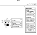
- the plasma processing apparatus 1 has a processing unit 10 and a storage unit 11.
- the processing unit 10 processes the wafer (sample 102) by generating plasma 101 inside the processing chamber 104 according to the set processing conditions.
- the storage unit 11 has a sensor value storage unit 12 and a management value storage unit 13.
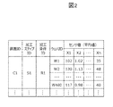
- the sensor value storage unit 12 stores the measured value of the sensor 103 of the apparatus during wafer processing for each processing step set as time series data.
- the sensor 103 constitutes a state sensor group and measures temperature and pressure.
- the sensor value storage unit 12 calculates and stores main statistical values (for example, average value or standard deviation) from time series data for use in device diagnosis. In this embodiment, this statistical value will be used as a sensor value thereafter.
- main statistical values for example, average value or standard deviation
- the average value is used as the statistical value.
- Each column of sensor values corresponds to the type of sensor, and each row corresponds to each wafer.
- Information such as an apparatus ID, a processing step ID, a processing condition ID, and a wafer ID is stored together with the sensor value.
- the device ID is information that identifies the plasma processing device 1 that has performed the processing.
- the processing step ID and the processing condition ID are information for specifying the processing step and the processing condition, respectively, and are used to specify the monitoring target.
- the wafer ID stores information that identifies the processed wafer.
- the management value storage unit 13 stores management values such as processing date and time and processing conditions.
- the device diagnostic device 2 is a computer having a common unit 20, an individual control unit 23, and a storage unit 26.
- the device diagnostic device 2 and the device group 3 of the plasma processing device 1 are connected via a network, and data communication is possible with each other.
- the device group 3 includes an existing device group A in which a large amount of sensor values are accumulated, and a device group which is a device diagnosis target in which a large amount of sensor values are not accumulated for reasons such as device startup. It is described separately as B.
- the apparatus group A does not necessarily have to have a plurality of plasma processing apparatuses 1 as long as there is a plasma processing apparatus 1 serving as a reference.
- the device group B to be diagnosed does not necessarily have to have the plurality of plasma processing devices 1.
- the common unit 20 has a common distribution function selection unit 21 and a prior distribution setting unit 22, and prior to performing the device diagnosis of the device group B, the prior distribution information for each sensor from the sensor values accumulated in the device group A in advance. Is extracted and stored in the prior distribution storage unit 27 included in the storage unit 26. An example of the processing content of the common unit 20 will be described in (3) Processing of common unit described later.
- the individual control unit 23 has a probability distribution estimation unit 24 and a device state diagnosis unit 25.
- the probability distribution estimation unit 24 estimates a probability distribution followed by each sensor 103 as a posterior distribution from the sensor value of each plasma processing apparatus of the apparatus group B acquired at the time of apparatus state diagnosis and the extracted prior distribution information, and the probability distribution It is stored in the storage unit 28.
- the device state diagnosis unit 25 calculates a device state value such as a difference between devices and stores it in the device diagnosis value storage unit 29.
- a device state value such as a difference between devices
- the device diagnosis value storage unit 29 An example of the processing content of the individual processing unit 23 will be described in (4) Processing of individual processing unit described later.
- An output unit 40 and an input unit 41 are connected to the device group 3 and the device diagnostic device 2.
- the output unit 40 is, for example, a display or a printer, and is a device that graphically outputs information to the user based on the information in the storage unit 26.
- a display example will be described in (5) Display example by output unit described later.
- the input unit 41 is, for example, an input device such as a mouse or a keyboard that receives information input by a user operation.
- a sensor value which is a history of plasma processing in the processing step to be monitored, is stored in the sensor value storage unit 12 in advance. ..
- a plasma process for example, an aging process or a cleaning process for adjusting the state of the processing unit 10 commonly performed in a plurality of processes is designated.
- the sensor value storage unit 12 of the device group A From the sensor value storage unit 12 of the device group A, the sensor value of the designated processing step ID is acquired. (S101)
- the sensor value accumulated by the device group A is set in the prior distribution. Can be used for.
- the prior distribution setting unit 22 executes the processes of S103 to S104 for each sensor 103 and each probability distribution function candidate.
- the probability distribution function candidate is a probability distribution function that each sensor 103 of the plasma processing apparatus 1 can follow as a candidate.
- a normal distribution, a skewed normal distribution, a mixed normal distribution, a Cauchy distribution, etc. are set as probability distribution function candidates (S102).
- the prior distribution setting unit 22 estimates the probability distribution parameter of the probability distribution function candidate for the sensor value of the sensor 103.
- the probability distribution parameter is, for example, a value corresponding to the average value and the standard deviation in the case of normal distribution, and has different types for each probability distribution function.
- the Markov chain Monte Carlo method (Markov Chain Monte Carlo method, MCMC method) is used to estimate the probability distribution parameter, for example.
- the MCMC method considers the probability distribution parameter as a random variable, and then generates a large number of random samples from the product of the prior distribution and the likelihood of the probability distribution parameter proportional to the posterior distribution of the probability distribution parameter to generate the posterior probability distribution parameter. This is a method for estimating the distribution (S103).
- the estimated probability distribution parameter is obtained as a probability distribution, but for example, the value is uniquely determined from the value that maximizes the posterior probability.
- the prior distribution setting unit 22 uses the probability distribution at this time, calculates the log likelihood, which is the degree of fitting of the obtained sensor values of the device group A (S104).
- the common distribution function selection unit 21 selects, from the probability distribution function candidates, the probability distribution function having the maximum log likelihood as the probability distribution function common to the device group A for each sensor 103. .. Further, the estimated value of the probability distribution parameter regarding the selected probability distribution function is stored in the prior distribution storage unit 27 as the prior distribution when estimating the probability distribution of the sensor values of the device group B. Further, the estimated value of the probability distribution parameter regarding the normal distribution is also stored in the prior distribution storage unit 27 together with the probability distribution function with the maximum log-likelihood (S105).
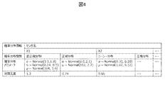
- the information of prior distribution is stored for each sensor.
- the row of the probability distribution function stores the name of the probability distribution function selected in S105 of FIG.
- the probability distribution parameter row stores the prior distribution of each probability distribution parameter set using the posterior distribution of the probability distribution parameter estimated in S103 of FIG. As an example, a normal distribution having the mean and standard deviation of the posterior distribution is set as the prior distribution of each probability distribution parameter.
- the log likelihood row stores the log likelihood calculated in S104 of FIG.
- the sensor value of the processing step ID specified in S101 of FIG. 3 is acquired from the sensor value storage unit 12 of the plasma processing apparatus 1 that is the diagnosis target of the apparatus group B (S201).
- the probability distribution estimation unit 24 executes the processing of S203 to S205 for each sensor of the acquired sensor value (S202).
- the prior distribution information corresponding to the sensor is acquired from the prior distribution storage unit 27 (S203).
- the posterior distribution of the probability distribution parameter is estimated by the MCMC method using the acquired sensor values.
- the log likelihood with respect to the sensor value is calculated in the same manner as S104 in FIG. This process is performed for both the probability distribution function selected in S105 of FIG. 3 and the normal distribution (S204).
- the log-likelihood is compared between the probability distribution estimated by the probability distribution function selected in S105 of FIG. 3 and the probability distribution estimated by the normal distribution, and the probability distribution having a large log-likelihood is set as the estimation result for the sensor, It is stored in the probability distribution storage unit 28 (S205).
- the robustness of the estimation result can be enhanced by determining the probability distribution function together with the sensor value of the device group B.
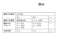
- probability distribution information is stored for each sensor shown in each column of sensor names.
- the probability distribution information to be stored is the probability distribution function, the probability distribution parameter, and the log likelihood, as in FIG.
- the probability distribution parameter may store the estimated posterior distribution in the same manner as in FIG. 4, or may store a uniquely determined value such as a value that maximizes the posterior probability as in FIGS. 6A and 6B. good.
- the probability distribution with a large log likelihood is determined, and this corresponds to FIG. 6B.
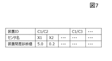
- the device diagnostic value is calculated using the data stored in the probability distribution storage unit 28 (S206). For example, when calculating the difference between devices as the device diagnostic value, first, the probability distribution information of the reference plasma processing device 1 and the plasma processing device 1 to be diagnosed is acquired from the probability distribution storage unit 28. The acquired distance between the probability distributions is stored in the device state diagnostic value storage unit 29 as an inter-device difference diagnostic value. As a distance index between probability distributions, Kullback-Leibler divergence, Jensen-Shannon divergence, or the like is used.
- the device ID row stores an ID that identifies the two plasma processing devices 1 to be compared.
- the device-to-device difference diagnosis value row stores the device-to-device difference diagnosis value calculated for each sensor.
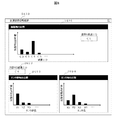
- the output unit 40 uses the information stored in the storage unit 11 and the storage unit 26 to display the diagnosis result of the device state and the estimation result of the probability distribution.
- the inter-device difference diagnosis value of the corresponding device ID stored in the device state value storage unit 29 is acquired, and is displayed as a graph for each sensor as in D104.
- a sensor having a large difference between the reference plasma processing apparatus 1 and the apparatus can be determined and can be used for adjustment or the like.
- the sensor 103 can be generally classified into a plurality of groups according to measurement target parts, measurement target items, and the like. It is registered in advance as a sensor group, and the device difference diagnostic value of each sensor belonging to the sensor group is integrated, and the device difference diagnostic value is displayed for each sensor group, as in D103. By doing so, the parts to be adjusted become clear.
- the histogram is a histogram of the measured values of the sensor values stored in the sensor value storage unit 12, and the solid line is the probability distribution estimation result stored in the probability distribution storage unit 28.
- the histogram of the sensor values of the sensor name X2 of the devices having the device IDs C1 and C4 and the estimation result of the probability distribution are displayed. This allows the user to confirm whether the estimated probability distribution is valid. Further, for example, when the two probability distributions to be compared are moving in parallel, the initialization of the sensor 103 is considered, and the like, which can be utilized for devising a countermeasure against the device diagnosis result.
- the output unit 40 outputs the difference between the plasma processing apparatuses in the probability distribution as the diagnostic value of the state of the plasma processing apparatus 1, and also changes the transition width of the probability distribution over time. Output.
- the device diagnosis can be performed by extracting the prior distribution information common to the device group and then estimating the probability distribution including the non-normal distribution together with the sensor value newly acquired by the device to be diagnosed.
- FIG. 1 shows a configuration in which the apparatus diagnostic device 2 and the plasma processing apparatus 1 are connected via a network, but the present invention is not limited to the above configuration, and as shown in FIG. May include the device diagnostic device 2.
- the plasma processing apparatus 1 includes a processing chamber 104 in which the sample 102 is plasma-processed and an apparatus diagnostic apparatus 2 that diagnoses the state of the apparatus itself.
- the plasma processing apparatus 1 has the processing unit 10 and the storage unit 11 shown in FIG.
- the processing unit 10 processes the wafer (sample 102) by generating plasma 101 inside the processing chamber 104 according to the set processing conditions.
- the device diagnosis device 2 has a common unit 20, an individual control unit 23, and a storage unit 26, similarly to the configuration shown in FIG.
Landscapes
- Physics & Mathematics (AREA)
- Engineering & Computer Science (AREA)
- General Physics & Mathematics (AREA)
- Theoretical Computer Science (AREA)
- Analytical Chemistry (AREA)
- Chemical & Material Sciences (AREA)
- Plasma & Fusion (AREA)
- Mathematical Optimization (AREA)
- Mathematical Physics (AREA)
- Mathematical Analysis (AREA)
- Data Mining & Analysis (AREA)
- Pure & Applied Mathematics (AREA)
- Computing Systems (AREA)
- General Engineering & Computer Science (AREA)
- Evolutionary Computation (AREA)
- Software Systems (AREA)
- Computational Mathematics (AREA)
- Artificial Intelligence (AREA)
- Algebra (AREA)
- Probability & Statistics with Applications (AREA)
- Automation & Control Theory (AREA)
- Drying Of Semiconductors (AREA)
Abstract
Description
図1を参照して、プラズマ処理装置1の構成について説明する。
図1を参照して、装置診断装置2の構成について説明する。
図3を参照して、装置診断装置2の共通部20で行われる装置群Aのセンサ値を用いて事前分布を設定する処理の例について説明する。
このように複数の工程で共通に行うプラズマ処理のセンサ値を用いることで、例えば装置群Bが新規工程への適用の際であっても、装置群Aが蓄積したセンサ値を事前分布の設定に利用することができる。
図5を参照して、装置診断装置2の個別制御部23で行われる確率分布の推定と装置診断の処理の例について説明する。
出力部40は、記憶部11や記憶部26に格納された情報を用いて、装置状態の診断結果や確率分布の推定結果を表示する。
2 装置診断装置
3 装置群
10 処理部
11 記憶部
12 センサ値記憶部
13 管理値記憶部
20 共通部
21 共通分布関数選択部
22 事前分布設定部
23 個別制御部
24 確率分布推定部
25 装置状態診断部
26 記憶部
27 事前分布記憶部
28 確率分布記憶部
29 装置診断値記憶部
40 出力部
41 入力部
Claims (8)
- プラズマ処理装置の状態を診断する装置診断装置において、
第一のプラズマ処理装置における第一のセンサにより取得された第一のセンサ値を用いて確率分布関数を含む事前分布情報を前記第一のセンサの各々に対して予め求め、前記予め求められた事前分布情報と、前記第一のプラズマ処理装置と異なる第二のプラズマ処理装置における第二のセンサにより取得された第二のセンサ値とを基に前記第一のセンサの各々に対応する前記第二のセンサの各々における確率分布を推定し、前記推定された確率分布を用いて前記第二のプラズマ処理装置の状態を診断することを特徴とする装置診断装置。 - 請求項1に記載の装置診断装置において、
前記第一のプラズマ処理装置は、複数であり、
前記第一のセンサの各々における予め求められた確率分布関数は、前記第一のプラズマ処理装置の各々に対して求められた確率分布関数の中で最も多くの前記第一のプラズマ処理装置に求められた確率分布関数であることを特徴とする装置診断装置。 - 請求項2に記載の装置診断装置において、
前記第一のセンサの各々における予め求められた確率分布関数は、確率分布関数の候補の中から尤度を基に選択されることを特徴とする装置診断装置。 - プラズマ処理装置の状態を診断する装置診断装置において、
第一のプラズマ処理装置における第一のセンサにより取得された第一のセンサ値を用いて確率分布関数を含む事前分布情報を前記第一のセンサの各々に対して予め求め、前記予め求められた事前分布情報と、第二のプラズマ処理装置における第二のセンサにより取得された第二のセンサ値とを基に前記第一のセンサの各々に対応する前記第二のセンサの各々における確率分布を推定し、前記推定された確率分布に対する尤度である第一の尤度と、正規分布に対する尤度である第二の尤度とを比較し、
前記第一の尤度が前記第二の尤度より大きい場合、前記推定された確率分布を用いて前記第二のプラズマ処理装置の状態を診断し、
前記第二の尤度が前記第一の尤度より大きい場合、前記正規分布を用いて前記第二のプラズマ処理装置の状態を診断することを特徴とする装置診断装置。 - 請求項1に記載の装置診断装置において、
前記確率分布は、マルコフ連鎖モンテカルロ法を用いて推定されることを特徴とする装置診断装置。 - 請求項1に記載の装置診断装置において、
前記第二のプラズマ処理装置の状態の診断値として前記確率分布のプラズマ処理装置間差を出力するとともに前記確率分布の経時的な推移幅も出力することを特徴とする装置診断装置。 - 試料がプラズマ処理される処理室と自装置の状態を診断する装置診断装置とを備えるプラズマ処理装置において、
前記装置診断装置は、自装置と異なるプラズマ処理装置における第一のセンサにより取得された第一のセンサ値を用いて確率分布関数を含む事前分布情報を前記第一のセンサの各々に対して予め求め、前記予め求められた事前分布情報と、自装置における第二のセンサにより取得された第二のセンサ値とを基に前記第一のセンサの各々に対応する前記第二のセンサの各々における確率分布を推定し、前記推定された確率分布を用いて前記自装置の状態を診断することを特徴とするプラズマ処理装置。 - プラズマ処理装置の状態を診断する装置診断方法において、
第一のプラズマ処理装置における第一のセンサにより取得された第一のセンサ値を用いて確率分布関数を含む事前分布情報を前記第一のセンサの各々に対して予め求める工程と、
前記予め求められた事前分布情報と、第二のプラズマ処理装置における第二のセンサにより取得された第二のセンサ値とを基に前記第一のセンサの各々に対応する前記第二のセンサの各々における確率分布を推定する工程と、
前記推定された確率分布を用いて前記第二のプラズマ処理装置の状態を診断する工程とを有することを特徴とする装置診断方法。
Priority Applications (6)
| Application Number | Priority Date | Filing Date | Title |
|---|---|---|---|
| CN201980007659.0A CN112585727B (zh) | 2019-07-30 | 2019-07-30 | 装置诊断装置、等离子体处理装置以及装置诊断方法 |
| JP2020532826A JP6841980B2 (ja) | 2019-07-30 | 2019-07-30 | 装置診断装置、プラズマ処理装置及び装置診断方法 |
| US16/971,255 US12040167B2 (en) | 2019-07-30 | 2019-07-30 | Diagnosis apparatus, plasma processing apparatus and diagnosis method |
| KR1020207017597A KR102425936B1 (ko) | 2019-07-30 | 2019-07-30 | 장치 진단 장치, 플라스마 처리 장치 및 장치 진단 방법 |
| PCT/JP2019/029762 WO2020152889A1 (ja) | 2019-07-30 | 2019-07-30 | 装置診断装置、プラズマ処理装置及び装置診断方法 |
| TW109122971A TWI738411B (zh) | 2019-07-30 | 2020-07-08 | 裝置診斷裝置、電漿處理裝置及裝置診斷方法 |
Applications Claiming Priority (1)
| Application Number | Priority Date | Filing Date | Title |
|---|---|---|---|
| PCT/JP2019/029762 WO2020152889A1 (ja) | 2019-07-30 | 2019-07-30 | 装置診断装置、プラズマ処理装置及び装置診断方法 |
Publications (1)
| Publication Number | Publication Date |
|---|---|
| WO2020152889A1 true WO2020152889A1 (ja) | 2020-07-30 |
Family
ID=71736287
Family Applications (1)
| Application Number | Title | Priority Date | Filing Date |
|---|---|---|---|
| PCT/JP2019/029762 Ceased WO2020152889A1 (ja) | 2019-07-30 | 2019-07-30 | 装置診断装置、プラズマ処理装置及び装置診断方法 |
Country Status (6)
| Country | Link |
|---|---|
| US (1) | US12040167B2 (ja) |
| JP (1) | JP6841980B2 (ja) |
| KR (1) | KR102425936B1 (ja) |
| CN (1) | CN112585727B (ja) |
| TW (1) | TWI738411B (ja) |
| WO (1) | WO2020152889A1 (ja) |
Cited By (3)
| Publication number | Priority date | Publication date | Assignee | Title |
|---|---|---|---|---|
| CN113015308A (zh) * | 2021-03-17 | 2021-06-22 | 中国科学技术大学 | 一种等离子体电流计算方法及装置 |
| WO2023286142A1 (ja) * | 2021-07-13 | 2023-01-19 | 株式会社日立ハイテク | 診断装置及び診断方法並びにプラズマ処理装置及び半導体装置製造システム |
| JPWO2023148967A1 (ja) * | 2022-02-07 | 2023-08-10 |
Citations (6)
| Publication number | Priority date | Publication date | Assignee | Title |
|---|---|---|---|---|
| JP2002270581A (ja) * | 2001-03-07 | 2002-09-20 | Hitachi Ltd | プラズマ処理装置及び処理方法 |
| JP2003347275A (ja) * | 2002-05-30 | 2003-12-05 | Toshiba Corp | 半導体製造装置の管理値設定装置 |
| JP2010165949A (ja) * | 2009-01-16 | 2010-07-29 | Ritsumeikan | パーティクル汚染事象予測装置、パーティクル汚染事象予測方法、及び、パーティクル汚染事象予測プログラム |
| JP2013041954A (ja) * | 2011-08-15 | 2013-02-28 | Hitachi High-Technologies Corp | プラズマ処理装置およびプラズマ処理方法 |
| JP2014022695A (ja) * | 2012-07-24 | 2014-02-03 | Hitachi High-Technologies Corp | プラズマ処理装置及びその校正方法 |
| WO2018061842A1 (ja) * | 2016-09-27 | 2018-04-05 | 東京エレクトロン株式会社 | 異常検知プログラム、異常検知方法および異常検知装置 |
Family Cites Families (28)
| Publication number | Priority date | Publication date | Assignee | Title |
|---|---|---|---|---|
| US6214119B1 (en) * | 1986-04-18 | 2001-04-10 | Applied Materials, Inc. | Vacuum substrate processing system having multiple processing chambers and a central load/unload chamber |
| US5347460A (en) * | 1992-08-25 | 1994-09-13 | International Business Machines Corporation | Method and system employing optical emission spectroscopy for monitoring and controlling semiconductor fabrication |
| JP3977114B2 (ja) * | 2002-03-25 | 2007-09-19 | 株式会社ルネサステクノロジ | プラズマ処理装置 |
| KR100628392B1 (ko) * | 2002-06-05 | 2006-09-26 | 동경 엘렉트론 주식회사 | 처리 장치의 다변량 해석 모델식 작성 방법, 처리장치용의 다변량 해석 방법, 처리 장치의 제어 장치, 처리장치의 제어 시스템 |
| US7072811B2 (en) * | 2002-07-15 | 2006-07-04 | Carnegie Mellon University | Method and system for identifying regeneration points in a Markov chain Monte Carlo simulation |
| US6927076B2 (en) * | 2002-10-05 | 2005-08-09 | Taiwan Semiconductor Manufacturing Co., Ltd | Method for recovering a plasma process |
| US7050880B2 (en) * | 2003-12-30 | 2006-05-23 | Sc Solutions | Chemical-mechanical planarization controller |
| US7555152B2 (en) * | 2005-01-06 | 2009-06-30 | Siemens Medical Solutions Usa, Inc. | System and method for detecting ground glass nodules in medical images |
| CN100359660C (zh) * | 2005-01-27 | 2008-01-02 | 北京北方微电子基地设备工艺研究中心有限责任公司 | 一种等离子体刻蚀工艺的终点检测方法 |
| JP4170315B2 (ja) * | 2005-05-30 | 2008-10-22 | インターナショナル・ビジネス・マシーンズ・コーポレーション | 異常判断装置、制御方法、自動車およびプログラム |
| US8366829B2 (en) * | 2005-08-05 | 2013-02-05 | Advanced Micro-Fabrication Equipment, Inc. Asia | Multi-station decoupled reactive ion etch chamber |
| JP4754419B2 (ja) * | 2006-07-03 | 2011-08-24 | 学校法人立命館 | プラズマ異常放電診断方法、プラズマ異常放電診断システム及びコンピュータプログラム |
| JP2008218898A (ja) * | 2007-03-07 | 2008-09-18 | Hitachi High-Technologies Corp | プラズマ処理装置 |
| JP5353265B2 (ja) * | 2009-01-26 | 2013-11-27 | パナソニック株式会社 | プラズマ処理装置 |
| JP2010283000A (ja) | 2009-06-02 | 2010-12-16 | Renesas Electronics Corp | 半導体製造における装置異常の予兆検知方法 |
| JP5363213B2 (ja) * | 2009-06-30 | 2013-12-11 | 東京エレクトロン株式会社 | 異常検出システム、異常検出方法、記憶媒体及び基板処理装置 |
| KR101117928B1 (ko) * | 2010-06-07 | 2012-02-29 | 명지대학교 산학협력단 | 플라즈마 공정 진단 시스템 및 이에 있어서 종료점 검출 방법 및 장치 |
| JP5436351B2 (ja) * | 2010-06-21 | 2014-03-05 | 日本電信電話株式会社 | 状態推定装置、状態推定方法、およびプログラム |
| US8581217B2 (en) * | 2010-10-08 | 2013-11-12 | Advanced Ion Beam Technology, Inc. | Method for monitoring ion implantation |
| JP5773613B2 (ja) * | 2010-10-25 | 2015-09-02 | 東京エレクトロン株式会社 | 異常原因分析方法及び異常分析プログラム |
| JP5259797B2 (ja) | 2011-09-05 | 2013-08-07 | 株式会社東芝 | 学習型プロセス異常診断装置、およびオペレータ判断推測結果収集装置 |
| JP5791555B2 (ja) * | 2012-03-23 | 2015-10-07 | 日本電信電話株式会社 | 状態追跡装置、方法、及びプログラム |
| KR102102003B1 (ko) * | 2012-05-25 | 2020-04-20 | 도쿄엘렉트론가부시키가이샤 | 플라즈마 처리 장치, 및 플라즈마 처리 방법 |
| JP2016103496A (ja) * | 2014-11-27 | 2016-06-02 | 株式会社日立ハイテクノロジーズ | プラズマ処理装置 |
| US10043690B2 (en) * | 2015-03-31 | 2018-08-07 | Lam Research Corporation | Fault detection using showerhead voltage variation |
| JP6462477B2 (ja) * | 2015-04-27 | 2019-01-30 | 東京エレクトロン株式会社 | 被処理体を処理する方法 |
| US9892012B2 (en) * | 2015-12-30 | 2018-02-13 | International Business Machines Corporation | Detecting anomalous sensors |
| US10817796B2 (en) * | 2016-03-07 | 2020-10-27 | D-Wave Systems Inc. | Systems and methods for machine learning |
-
2019
- 2019-07-30 CN CN201980007659.0A patent/CN112585727B/zh active Active
- 2019-07-30 JP JP2020532826A patent/JP6841980B2/ja active Active
- 2019-07-30 WO PCT/JP2019/029762 patent/WO2020152889A1/ja not_active Ceased
- 2019-07-30 KR KR1020207017597A patent/KR102425936B1/ko active Active
- 2019-07-30 US US16/971,255 patent/US12040167B2/en active Active
-
2020
- 2020-07-08 TW TW109122971A patent/TWI738411B/zh active
Patent Citations (6)
| Publication number | Priority date | Publication date | Assignee | Title |
|---|---|---|---|---|
| JP2002270581A (ja) * | 2001-03-07 | 2002-09-20 | Hitachi Ltd | プラズマ処理装置及び処理方法 |
| JP2003347275A (ja) * | 2002-05-30 | 2003-12-05 | Toshiba Corp | 半導体製造装置の管理値設定装置 |
| JP2010165949A (ja) * | 2009-01-16 | 2010-07-29 | Ritsumeikan | パーティクル汚染事象予測装置、パーティクル汚染事象予測方法、及び、パーティクル汚染事象予測プログラム |
| JP2013041954A (ja) * | 2011-08-15 | 2013-02-28 | Hitachi High-Technologies Corp | プラズマ処理装置およびプラズマ処理方法 |
| JP2014022695A (ja) * | 2012-07-24 | 2014-02-03 | Hitachi High-Technologies Corp | プラズマ処理装置及びその校正方法 |
| WO2018061842A1 (ja) * | 2016-09-27 | 2018-04-05 | 東京エレクトロン株式会社 | 異常検知プログラム、異常検知方法および異常検知装置 |
Cited By (11)
| Publication number | Priority date | Publication date | Assignee | Title |
|---|---|---|---|---|
| CN113015308A (zh) * | 2021-03-17 | 2021-06-22 | 中国科学技术大学 | 一种等离子体电流计算方法及装置 |
| CN113015308B (zh) * | 2021-03-17 | 2022-07-15 | 中国科学技术大学 | 一种等离子体电流计算方法及装置 |
| WO2023286142A1 (ja) * | 2021-07-13 | 2023-01-19 | 株式会社日立ハイテク | 診断装置及び診断方法並びにプラズマ処理装置及び半導体装置製造システム |
| KR20230012453A (ko) * | 2021-07-13 | 2023-01-26 | 주식회사 히타치하이테크 | 진단 장치 및 진단 방법 그리고 플라스마 처리 장치 및 반도체 장치 제조 시스템 |
| JP7289992B1 (ja) * | 2021-07-13 | 2023-06-12 | 株式会社日立ハイテク | 診断装置及び診断方法並びにプラズマ処理装置及び半導体装置製造システム |
| TWI854254B (zh) * | 2021-07-13 | 2024-09-01 | 日商日立全球先端科技股份有限公司 | 診斷裝置及診斷方法以及電漿處理裝置及半導體裝置製造系統 |
| KR102797798B1 (ko) * | 2021-07-13 | 2025-04-22 | 주식회사 히타치하이테크 | 진단 장치 및 진단 방법 그리고 플라스마 처리 장치 및 반도체 장치 제조 시스템 |
| US12444591B2 (en) | 2021-07-13 | 2025-10-14 | Hitachi High-Tech Corporation | Diagnosis device, diagnosis method, plasma processing apparatus, and semiconductor device manufacturing system |
| JPWO2023148967A1 (ja) * | 2022-02-07 | 2023-08-10 | ||
| WO2023148967A1 (ja) * | 2022-02-07 | 2023-08-10 | 株式会社日立ハイテク | 診断装置、診断方法、半導体製造装置システム及び半導体装置製造システム |
| JP7442013B2 (ja) | 2022-02-07 | 2024-03-01 | 株式会社日立ハイテク | 診断装置、診断方法、半導体製造装置システム及び半導体装置製造システム |
Also Published As
| Publication number | Publication date |
|---|---|
| JP6841980B2 (ja) | 2021-03-10 |
| US20220157580A1 (en) | 2022-05-19 |
| CN112585727B (zh) | 2023-09-29 |
| KR102425936B1 (ko) | 2022-07-28 |
| TWI738411B (zh) | 2021-09-01 |
| KR20210015741A (ko) | 2021-02-10 |
| CN112585727A (zh) | 2021-03-30 |
| JPWO2020152889A1 (ja) | 2021-02-18 |
| US12040167B2 (en) | 2024-07-16 |
| TW202105107A (zh) | 2021-02-01 |
Similar Documents
| Publication | Publication Date | Title |
|---|---|---|
| CN102474968B (zh) | 预测刻蚀率均匀性以评测校正等离子体腔的方法和装置 | |
| CN1324515C (zh) | 处理工具优化系统和方法 | |
| US8295966B2 (en) | Methods and apparatus to predict etch rate uniformity for qualification of a plasma chamber | |
| KR101019459B1 (ko) | 결함 진단을 위한 분류된 결함 시그니처들 | |
| US8989888B2 (en) | Automatic fault detection and classification in a plasma processing system and methods thereof | |
| US7809450B2 (en) | Self-correcting multivariate analysis for use in monitoring dynamic parameters in process environments | |
| US7844558B2 (en) | Incremental learning of nonlinear regression networks for machine condition monitoring | |
| JP6841980B2 (ja) | 装置診断装置、プラズマ処理装置及び装置診断方法 | |
| KR20090007634A (ko) | 적응형 다변수 결함 검출 | |
| US20190196458A1 (en) | Method for selecting leading associated parameter and method for combining critical parameter and leading associated parameter for equipment prognostics and health management | |
| JP7290484B2 (ja) | 異常検知装置、異常検知システム、及び異常検知方法 | |
| CN115803849A (zh) | 信息处理方法以及信息处理装置 | |
| JP2009080612A (ja) | 分布の評価方法、製品の製造方法、分布の評価プログラム及び分布の評価システム | |
| KR102797798B1 (ko) | 진단 장치 및 진단 방법 그리고 플라스마 처리 장치 및 반도체 장치 제조 시스템 | |
| US12429859B2 (en) | Method for controlling a production process for producing components | |
| KR20160099389A (ko) | 반도체 제조 공정에서 통계적 방법을 이용하여, 가스 누출을 감지하는 방법 장치 | |
| CN117063065A (zh) | 诊断装置、半导体制造装置系统、半导体装置制造系统以及诊断方法 | |
| KR20250143792A (ko) | 데이터 취급 장치, 및, 데이터 취급 방법 | |
| TW202514853A (zh) | 製程處理裝置的診斷裝置、診斷系統及診斷方法 | |
| JP2025517079A (ja) | マルチラン周期処理手順の分析 | |
| JP2005277290A (ja) | 歩留解析装置及び歩留解析方法 |
Legal Events
| Date | Code | Title | Description |
|---|---|---|---|
| ENP | Entry into the national phase |
Ref document number: 2020532826 Country of ref document: JP Kind code of ref document: A |
|
| ENP | Entry into the national phase |
Ref document number: 20207017597 Country of ref document: KR Kind code of ref document: A |
|
| 121 | Ep: the epo has been informed by wipo that ep was designated in this application |
Ref document number: 19911235 Country of ref document: EP Kind code of ref document: A1 |
|
| NENP | Non-entry into the national phase |
Ref country code: DE |
|
| 122 | Ep: pct application non-entry in european phase |
Ref document number: 19911235 Country of ref document: EP Kind code of ref document: A1 |