WO2020149139A1 - イメージング装置、その演算処理装置、車両用灯具、車両、センシング方法 - Google Patents
イメージング装置、その演算処理装置、車両用灯具、車両、センシング方法 Download PDFInfo
- Publication number
- WO2020149139A1 WO2020149139A1 PCT/JP2019/051192 JP2019051192W WO2020149139A1 WO 2020149139 A1 WO2020149139 A1 WO 2020149139A1 JP 2019051192 W JP2019051192 W JP 2019051192W WO 2020149139 A1 WO2020149139 A1 WO 2020149139A1
- Authority
- WO
- WIPO (PCT)
- Prior art keywords
- intensity
- reference light
- random
- detection
- pattern
- Prior art date
- Legal status (The legal status is an assumption and is not a legal conclusion. Google has not performed a legal analysis and makes no representation as to the accuracy of the status listed.)
- Ceased
Links
Images




Classifications
-
- B—PERFORMING OPERATIONS; TRANSPORTING
- B60—VEHICLES IN GENERAL
- B60Q—ARRANGEMENT OF SIGNALLING OR LIGHTING DEVICES, THE MOUNTING OR SUPPORTING THEREOF OR CIRCUITS THEREFOR, FOR VEHICLES IN GENERAL
- B60Q1/00—Arrangement of optical signalling or lighting devices, the mounting or supporting thereof or circuits therefor
- B60Q1/02—Arrangement of optical signalling or lighting devices, the mounting or supporting thereof or circuits therefor the devices being primarily intended to illuminate the way ahead or to illuminate other areas of way or environments
- B60Q1/24—Arrangement of optical signalling or lighting devices, the mounting or supporting thereof or circuits therefor the devices being primarily intended to illuminate the way ahead or to illuminate other areas of way or environments for lighting other areas than only the way ahead
- B60Q1/249—Arrangement of optical signalling or lighting devices, the mounting or supporting thereof or circuits therefor the devices being primarily intended to illuminate the way ahead or to illuminate other areas of way or environments for lighting other areas than only the way ahead for illuminating the field of view of a sensor or camera
-
- B—PERFORMING OPERATIONS; TRANSPORTING
- B60—VEHICLES IN GENERAL
- B60Q—ARRANGEMENT OF SIGNALLING OR LIGHTING DEVICES, THE MOUNTING OR SUPPORTING THEREOF OR CIRCUITS THEREFOR, FOR VEHICLES IN GENERAL
- B60Q1/00—Arrangement of optical signalling or lighting devices, the mounting or supporting thereof or circuits therefor
- B60Q1/02—Arrangement of optical signalling or lighting devices, the mounting or supporting thereof or circuits therefor the devices being primarily intended to illuminate the way ahead or to illuminate other areas of way or environments
- B60Q1/04—Arrangement of optical signalling or lighting devices, the mounting or supporting thereof or circuits therefor the devices being primarily intended to illuminate the way ahead or to illuminate other areas of way or environments the devices being headlights
- B60Q1/14—Arrangement of optical signalling or lighting devices, the mounting or supporting thereof or circuits therefor the devices being primarily intended to illuminate the way ahead or to illuminate other areas of way or environments the devices being headlights having dimming means
-
- G—PHYSICS
- G01—MEASURING; TESTING
- G01S—RADIO DIRECTION-FINDING; RADIO NAVIGATION; DETERMINING DISTANCE OR VELOCITY BY USE OF RADIO WAVES; LOCATING OR PRESENCE-DETECTING BY USE OF THE REFLECTION OR RERADIATION OF RADIO WAVES; ANALOGOUS ARRANGEMENTS USING OTHER WAVES
- G01S17/00—Systems using the reflection or reradiation of electromagnetic waves other than radio waves, e.g. lidar systems
- G01S17/88—Lidar systems specially adapted for specific applications
- G01S17/89—Lidar systems specially adapted for specific applications for mapping or imaging
-
- G—PHYSICS
- G01—MEASURING; TESTING
- G01S—RADIO DIRECTION-FINDING; RADIO NAVIGATION; DETERMINING DISTANCE OR VELOCITY BY USE OF RADIO WAVES; LOCATING OR PRESENCE-DETECTING BY USE OF THE REFLECTION OR RERADIATION OF RADIO WAVES; ANALOGOUS ARRANGEMENTS USING OTHER WAVES
- G01S17/00—Systems using the reflection or reradiation of electromagnetic waves other than radio waves, e.g. lidar systems
- G01S17/88—Lidar systems specially adapted for specific applications
- G01S17/93—Lidar systems specially adapted for specific applications for anti-collision purposes
-
- G—PHYSICS
- G01—MEASURING; TESTING
- G01S—RADIO DIRECTION-FINDING; RADIO NAVIGATION; DETERMINING DISTANCE OR VELOCITY BY USE OF RADIO WAVES; LOCATING OR PRESENCE-DETECTING BY USE OF THE REFLECTION OR RERADIATION OF RADIO WAVES; ANALOGOUS ARRANGEMENTS USING OTHER WAVES
- G01S7/00—Details of systems according to groups G01S13/00, G01S15/00, G01S17/00
- G01S7/48—Details of systems according to groups G01S13/00, G01S15/00, G01S17/00 of systems according to group G01S17/00
- G01S7/483—Details of pulse systems
- G01S7/486—Receivers
Definitions
- the present invention relates to an imaging device.
- An object identification system that senses the position and type of objects existing around the vehicle is used for automatic driving and automatic control of headlamp light distribution.
- the object identification system includes a sensor and an arithmetic processing unit that analyzes the output of the sensor.
- the sensor is selected from cameras, LiDAR (Light Detection and Ranging, Laser Imaging Detection and Ranging), millimeter wave radar, ultrasonic sonar, etc., in consideration of application, required accuracy and cost.
- Ghost imaging irradiates an object while randomly switching the intensity distribution (pattern) of reference light, and measures the light detection intensity of reflected light for each pattern.
- the photodetection intensity is an integrated value of energy or intensity over a plane, not an intensity distribution. Then, the correlation calculation between the corresponding pattern and the light detection intensity is performed, and the restored image of the object is reconstructed.
- the correlation function of Expression (1) is used for the correlation in ghost imaging.
- b r is the value of the detected intensity obtained when the reference light having the r-th intensity distribution is irradiated.
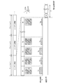
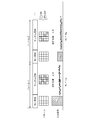
- FIG. 1 is a time chart showing sensing of one frame by the imaging device.
- the correlation calculation requires an average value ⁇ b> of M detection intensities b 1 to b M obtained for M times of irradiation of the reference light. Therefore, when the irradiation of M times is not completed, the correlation calculation cannot be started and the time delay ⁇ occurs. In an application requiring real-time property such as in-vehicle, it is required to minimize this time delay ⁇ .
- the detected intensity b r becomes small, and the S/N ratio decreases.
- the deterioration of the S/N ratio causes deterioration of the image quality of the restored image.
- the present invention has been made in such a situation, and one of the exemplary objects of a certain aspect thereof is to provide an imaging apparatus capable of shortening the time delay of image reconstruction. Further, one of exemplary purposes of another aspect is to provide an imaging apparatus capable of suppressing deterioration of image quality.
- One aspect of the present invention relates to an imaging device.
- the imaging device reconstructs a restored image of the object based on the illumination device that illuminates the reference light, the photodetector that measures the reflected light from the object, and the detection intensity based on the output of the photodetector and the intensity distribution of the reference light. And an arithmetic processing unit constituting the same.
- the reference light includes at least one standard pattern having a uniform intensity distribution and a plurality of random patterns. The intensity distribution of each random pattern is random, and the spatial average intensity is known.
- the arithmetic processing unit based on the reference detection intensity which is the detection intensity obtained when the reference light is the reference pattern, the detection intensity which is the average of the plurality of detection intensities obtained when the reference light is the plurality of random patterns. Get the average value.
- One aspect of the present invention relates to an imaging device.
- This imaging device is an illumination device that illuminates the reference light, a photodetector that measures the reflected light from the object, and a restored image of the object based on the detection intensity based on the output of the photodetector and the intensity distribution of the reference light.
- the reference light includes a plurality of random patterns having a random intensity distribution.
- An aspect of the present invention relates to an imaging device based on ghost imaging.
- the imaging device includes a photodetector that measures reflected light from the object, and an arithmetic processing device that reconstructs a restored image of the object based on the detected intensity based on the output of the photodetector and the intensity distribution of the reference light.
- Prepare The reference light includes at least one standard pattern having a uniform intensity distribution, and a plurality of random patterns having a random intensity distribution and a spatial average intensity of a predetermined value.
- the arithmetic processing unit sets the spatial average intensities of the plurality of random patterns based on the reference detection intensity that is the detection intensity obtained when the reference light is the reference pattern.
- the amount of calculation can be reduced or the image quality can be improved.
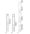
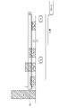
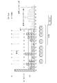
- FIG. 6 is a time chart showing sensing of one frame by the imaging device. It is a figure which shows the imaging device which concerns on embodiment. 6 is a time chart illustrating the operation of the imaging apparatus.
- FIGS. 4A to 4C are views for explaining sensing according to the modified example.
- FIG. 13 is a diagram illustrating the operation of the imaging device according to modification 5.
- FIG. 11 is a diagram illustrating the operation of the imaging device according to modification 6;
- FIG. 13 is a diagram illustrating the operation of the imaging device according to modification 7.
- FIG. 13 is a diagram illustrating the operation of the imaging device according to modification example 8.
- It is a block diagram of an object identification system. 1 is a block diagram of an automobile including an object identification system. It is a block diagram which shows the vehicle lamp provided with an object detection system.
- the "random intensity distribution” in the present specification does not mean that the intensity distribution is completely random, but may be random as long as an image can be reconstructed in ghost imaging. Therefore, “random” in the present specification can include a certain degree of regularity therein. Further, “random” does not require that the prediction is unpredictable, but may be predictable and reproducible.
- One embodiment disclosed herein relates to an imaging device.
- the imaging device reconstructs a restored image of the object based on the illumination device that illuminates the reference light, the photodetector that measures the reflected light from the object, and the detection intensity based on the output of the photodetector and the intensity distribution of the reference light.
- an arithmetic processing unit constituting the same.
- the reference light includes at least one standard pattern having a uniform intensity distribution and a plurality of random patterns. The intensity distribution of each random pattern is random, and the spatial average intensity is known.
- the arithmetic processing unit based on the reference detection intensity which is the detection intensity obtained when the reference light is the reference pattern, the detection intensity which is the average of the plurality of detection intensities obtained when the reference light is the plurality of random patterns. Get the average value.
- calculation for image reconstruction can be started without waiting for irradiation of all random patterns, and the calculation time can be shortened. Moreover, since it is not necessary to hold all the data obtained for M times of pattern irradiation in the memory, the hardware cost may be reduced in some cases.
- the reference pattern may be placed before multiple random patterns. Alternatively, the reference pattern may be inserted at the beginning of a plurality of random patterns.
- the calculation regarding irradiation of the random pattern may be performed, and when the difference is small, the calculation may be omitted. As a result, the amount of calculation can be reduced or a clear image can be obtained.
- Irradiation of multiple random patterns may be performed until the number of detected intensities whose difference from the average value of detected intensities is larger than the threshold value reaches a predetermined number. In this case, a clear image can be reconstructed.
- the spatial average intensity of multiple random patterns may be set based on the reference detection intensity. As a result, it is possible to perform sensing suitable for the size, reflectance, distance, and environment of the optical path of the reference light of the object to be detected.
- An embodiment disclosed in the present specification also relates to an imaging device.
- the imaging device reconstructs a restored image of the object based on the illumination device that illuminates the reference light, the photodetector that measures the reflected light from the object, and the detection intensity based on the output of the photodetector and the intensity distribution of the reference light. And an arithmetic processing unit constituting the same.
- the reference light includes a plurality of random patterns having a random intensity distribution.
- the arithmetic processing device when the difference between the detection intensity obtained for a certain random pattern and the detection intensity average value that is the average of the plurality of detection intensities obtained for a plurality of random patterns is larger than a threshold value, The calculation concerning the irradiation of the random pattern is performed, and when it is small, the calculation is omitted.
- the amount of calculation can be reduced.
- Irradiation of multiple random patterns may be performed until the number of detected intensities whose difference from the average value of detected intensities is larger than the threshold value reaches a predetermined number. In this case, a clear image can be reconstructed.
- the imaging device is an illumination device that illuminates the reference light, a photodetector that measures the reflected light from the object and outputs the detected intensity, and a reconstructed image of the object based on the detected intensity and the intensity distribution of the reference light.
- an arithmetic processing unit constituting the same.
- the reference light includes at least one standard pattern having a uniform intensity distribution and a plurality of random patterns.
- the intensity distribution of each random pattern is random, and the spatial average intensity is a predetermined value.
- the arithmetic processing unit utilizes the reference detection intensity which is the detection intensity obtained when the reference light is the reference pattern, and detects the average of the plurality of detection intensities obtained when the reference light is the plurality of random patterns. Calculate the mean intensity.
- calculation processing for image reconstruction can be started without waiting for irradiation of all random patterns, and calculation time can be shortened. Moreover, since it is not necessary to hold all the data obtained for M times of pattern irradiation in the memory, the hardware cost may be reduced in some cases.
- the reference pattern may be placed before multiple random patterns. Alternatively, the reference pattern may be inserted at the beginning of a plurality of random patterns.
- the calculation regarding irradiation of the random pattern may be performed, and when the difference is small, the calculation may be omitted. As a result, the amount of calculation can be reduced or a clear image can be obtained.
- Irradiation of multiple random patterns may be performed until the number of detected intensities whose difference from the average value of detected intensities is larger than the threshold value reaches a predetermined number. In this case, a clear image can be reconstructed.
- the spatial average intensity of multiple random patterns may be set based on the reference detection intensity. As a result, it is possible to perform sensing suitable for the size, reflectance, distance, and environment of the optical path of the reference light of the object to be detected.
- An embodiment disclosed in the present specification also relates to an imaging device.
- the imaging device is an illumination device that illuminates the reference light, a photodetector that measures the reflected light from the object and outputs the detected intensity, and a reconstructed image of the object based on the detected intensity and the intensity distribution of the reference light. And an arithmetic processing unit constituting the same.
- the reference light includes a plurality of random patterns having a random intensity distribution.
- the arithmetic processing device when the difference between the detection intensity obtained for a certain random pattern and the detection intensity average value that is the average of the plurality of detection intensities obtained for a plurality of random patterns is larger than a threshold value, The calculation concerning the irradiation of the random pattern is performed, and when it is small, the calculation is omitted.
- the amount of calculation can be reduced.
- Irradiation of multiple random patterns may be performed until the number of detected intensities whose difference from the average value of detected intensities is larger than the threshold value reaches a predetermined number. In this case, a clear image can be reconstructed.
- the imaging device uses a lighting device that illuminates the reference light, a photodetector that measures the reflected light from the object, and a detected image based on the output of the photodetector and the intensity distribution of the reference light, and a restored image of the object.
- an arithmetic processing unit to be reconfigured.
- the reference light includes at least one standard pattern having a uniform intensity distribution and a plurality of random patterns.
- the intensity distribution of each random pattern is random, and the spatial average intensity is a predetermined value.
- the arithmetic processing unit sets the spatial average intensities of the plurality of random patterns based on the reference detection intensity that is the detection intensity obtained when the reference light is the reference pattern.
- the reference detection intensity changes according to the size of the object, the reflectance, and the propagation loss between the imaging device and the object. According to this embodiment, it is possible to perform sensing suitable for the size, reflectance, distance, and environment of the optical path of the reference light of the object to be detected.
- the arithmetic processing unit may acquire a detection intensity average value, which is an average of a plurality of detection intensities obtained when the reference light has a plurality of random patterns, based on the reference detection intensity.
- a detection intensity average value which is an average of a plurality of detection intensities obtained when the reference light has a plurality of random patterns.
- the calculation regarding irradiation of the random pattern may be performed, and when the difference is small, the calculation may be omitted. As a result, the amount of calculation can be reduced or a clear image can be obtained.
- Irradiation of multiple random patterns may be performed until the number of detected intensities whose difference from the average value of detected intensities is larger than the threshold value reaches a predetermined number. In this case, a clear image can be reconstructed.
- An embodiment disclosed in the present specification also relates to an imaging device.
- the imaging device is an illumination device that illuminates the reference light, a photodetector that measures the reflected light from the object and outputs the detected intensity, and a reconstructed image of the object based on the detected intensity and the intensity distribution of the reference light. And an arithmetic processing unit constituting the same.
- the reference light includes a plurality of random patterns having a random intensity distribution.
- the arithmetic processing device when the difference between the detection intensity obtained for a certain random pattern and the detection intensity average value that is the average of the plurality of detection intensities obtained for a plurality of random patterns is larger than a threshold value, The calculation concerning the irradiation of the random pattern is performed, and when it is small, the calculation is omitted.
- the amount of calculation can be reduced.
- Irradiation of multiple random patterns may be performed until the number of detected intensities whose difference from the average value of detected intensities is larger than the threshold value reaches a predetermined number. In this case, a clear image can be reconstructed.
- FIG. 2 is a diagram showing an imaging device 100 according to the embodiment.
- the imaging device 100 is a single-pixel imaging device that uses the principle of ghost imaging, and includes an illumination device 110, a photodetector 120, and an arithmetic processing device 130.
- the imaging device 100 is also called a quantum radar camera.
- the lighting device 110 is a pseudo heat light source, and generates the reference light S1 having the intensity distribution I(x, y) that can be regarded as substantially random, and irradiates the object OBJ.
- the irradiation of the reference light S1 to the object OBJ is performed while randomly changing the intensity distribution thereof a plurality of M times.
- the lighting device 110 includes a light source 112, a patterning device 114, and a pattern generator 132.
- the light source 112 generates the light S0 having a uniform intensity distribution.
- the light source 112 may use a laser, a light emitting diode, or the like.
- the wavelength and spectrum of the reference light S1 are not particularly limited, and may be white light having a plurality of or continuous spectra, or monochromatic light having a predetermined wavelength.
- the wavelength of the reference light S1 may be infrared or ultraviolet.
- the patterning device 114 has a plurality of pixels arranged in a matrix, and the light intensity distribution I can be spatially modulated based on a combination of ON and OFF of the plurality of pixels.
- a pixel in an on state is referred to as an on pixel
- a pixel in an off state is referred to as an off pixel. Note that, in the following description, for ease of understanding, each pixel takes only two values (1, 0) of ON and OFF, but the present invention is not limited to this and may take an intermediate gradation.
- a reflective DMD Digital Micromirror Device
- a transmissive liquid crystal device can be used as the patterning device 114.
- a pattern signal PTN (image data) generated by the pattern generator 132 is applied to the patterning device 114.
- the photodetector 120 measures the reflected light from the object OBJ and outputs a detection signal D r .
- the detection signal D r is a spatial integral value of light energy (or intensity) incident on the photodetector 120 when the object OBJ is irradiated with the reference light having the intensity distribution I r . Therefore, the photodetector 120 can use a single-pixel photodetector (photodetector).
- the photodetector 120 outputs a plurality of detection signals D 1 to D M corresponding to a plurality of M intensity distributions I 1 to I M, respectively.
- the arithmetic processing unit 130 includes a pattern generator 132 and a reconstruction processing unit 134.
- the reconstruction processing unit 134 performs a correlation calculation of a plurality of intensity distributions (also referred to as random patterns) I 1 to I M and a plurality of detected intensities b 1 to b M to obtain a restored image G(x,y) of the object OBJ. Reconfigure.
- the detection intensities b 1 to b M are based on the detection signals D 1 to D M.
- the relationship between the detection intensity and the detection signal may be determined in consideration of the type and method of the photodetector 120.
- the detection signal D r is assumed to represent the amount of received light at a certain time (or a minute time), that is, an instantaneous value.
- the detection signal D r may be sampled a plurality of times during the irradiation period, and the detection intensity b r may be an integrated value, an average value, or a maximum value of all sampling values of the detection signal D r .
- some of all the sampling values may be selected, and the integrated value, average value, or maximum value of the selected sampling values may be used.
- the xth to yth order counting from the maximum value may be extracted, sampling values lower than an arbitrary threshold value may be excluded, or the magnitude of signal fluctuation may be excluded. It is also possible to extract a sampling value in a range where is smaller.
- the output D r of the photodetector 120 can be directly used as the detection intensity b r .
- the conversion from the detection signal D r to the detection intensity b r may be performed by the arithmetic processing device 130 or may be performed outside the arithmetic processing device 130.
- I r is the r-th intensity distribution
- b r is the r-th detected intensity value
- the processor 130 can be implemented by a combination of a processor (hardware) such as a CPU (Central Processing Unit), an MPU (Micro Processing Unit), and a microcomputer, and a software program executed by the processor (hardware).
- a processor such as a CPU (Central Processing Unit), an MPU (Micro Processing Unit), and a microcomputer
- the arithmetic processing unit 130 may be a combination of a plurality of processors. Alternatively, the arithmetic processing unit 130 may be composed of only hardware.
- the reference light S1 has at least one reference pattern having a uniform intensity distribution in addition to a plurality of random patterns I 1 to I M having a random intensity distribution and a spatial average intensity of a predetermined value.
- I 0 and.
- the reference pattern I 0 may be located before the plurality of random patterns I 1 to I M.
- the spatial average intensity of the reference light S1 is the average of the intensities of all the pixels of the patterning device 114.
- the intensity of the on pixel is associated with 1 and the intensity of the off pixel is associated with 0.
- the spatial average intensity is q/p, which is referred to as a lighting ratio ⁇ .
- the pattern generator 132 generates a plurality of random patterns I 1 to I M under the constraint condition that the lighting ratio ⁇ becomes the threshold value ⁇ a . It is not necessary more random patterns I 1 ⁇ I M each lighting ratio eta 1 ⁇ eta M matches exactly eta a, may have some errors.
- the spatial average intensity (lighting ratio ⁇ 0 ) of the reference pattern I 0 is 1.
- the reconstruction processing unit 134 of the arithmetic processing device 130 uses the reference detection intensity b 0 , which is the detection intensity obtained when the reference light S 1 has the reference pattern I 0 , and the reference light S 1 has a plurality of random patterns I.
- the detection intensity average value ⁇ b> which is the average of the plurality of detection intensities b 1 to b r obtained when 1 to I M , is calculated.
- f(x, y) represents the reflection characteristics of the object and the characteristics of the transmission paths of the reference light and the reflected light.
- the average intensity distribution ⁇ I(x,y)> of the M random patterns I 1 (x,y) to I M (x,y) is uniform, and ⁇ a ⁇ I 0 (x,y) ).
- the above is the configuration of the imaging apparatus 100. Next, the operation will be described.
- FIG. 3 is a time chart explaining the operation of the imaging apparatus 100.
- the reference pattern I 0 having a uniform intensity distribution is irradiated, and the corresponding reference detection intensity b 0 is measured.
- the reconstruction processing unit 134 calculates the detection intensity average value ⁇ b> based on the equation (2).
- the detection intensity average value ⁇ b> can be calculated when the irradiation of the reference pattern I 0 is completed. Therefore, after that, the correlation calculation can be advanced each time a new detection intensity b r is obtained. As a result, the restored image G can be obtained immediately after the Mth irradiation of the random pattern IM is completed, and the calculation delay can be reduced.
- b 1 to b M must be kept held until all the irradiations are completed, which increases the memory capacity.
- b r can be discarded after the calculation is completed, the memory capacity can be reduced.
- FIGS. 4A to 4C are views for explaining sensing according to the modified example.
- the reference pattern I 0 is inserted once in one frame, but this is not the only case.
- a plurality of reference patterns I 0 may be inserted in one frame.
- the detection intensity average value ⁇ b> may be calculated based on the average value of the plurality of reference detection intensities b 0 obtained corresponding to the plurality of reference patterns I0.
- one reference pattern I 0 may be emitted for every K continuous random patterns.
- an average value of K subsequent detection intensities (or preceding thereto) may be calculated.
- the reference pattern I0 has all pixels turned on, but this is not the case.
- an intermediate gradation can be designated as the intensity of each pixel
- the intensity of all pixels may be set to ⁇ a .
- Modification 5 In the modified example 5, when the difference
- FIG. 5 is a diagram illustrating an operation of the imaging device 100 according to the fifth modification.
- b 1 and b 3 the difference
- FIG. 6 is a diagram illustrating an operation of the imaging apparatus 100 according to the modified example 6.
- the detection intensity b r obtained for a random pattern I r the difference between the detected intensity average value ⁇ b>
- calculates regarding irradiation of the random pattern i.e. calculation section c r
- Section c r is omitted calculations is that excluded from the population mean. That is, the actual average number m becomes smaller for M random patterns I 1 to I M.
- a clear image can be obtained.
- Modification 7 is a modification of Modification 6.
- the number M′′ of random patterns prepared in advance is set to be larger than M, and the number m of detection intensities b r such that the difference from the detection intensity average value ⁇ b> is larger than the threshold value ⁇ .
- the pseudo-random signal generator it is not necessary to prepare M′′ patterns in advance, and it is sufficient to continue generating the patterns until m reaches M.
- FIG. 7 is a diagram illustrating an operation of the imaging apparatus 100 according to the modified example 7.
- > ⁇ is a predetermined value.
- FIG. 8 is a diagram illustrating an operation of the imaging apparatus 100 according to the modified example 8.
- the lighting ratio ⁇ a of each frame is determined based on the reference detection intensity b 0 obtained at the beginning of that frame.
- FIG. 8 shows two consecutive frames.
- the smaller the reference detection intensity b 0 the larger the spatial average intensity of a plurality of random patterns, that is, the lighting ratio ⁇ a , and conversely, the larger the reference detection intensity b 0 , the smaller the lighting ratio ⁇ a .
- ⁇ a may be substantially inversely proportional to b 0 .
- the illuminating device 110 is configured by the combination of the light source 112 and the patterning device 114, but it is not limited thereto.
- the illuminating device 110 is configured by an array of a plurality of semiconductor light sources (LED (light emitting diode) or LD (laser diode)) arranged in a matrix, and ON/OFF (or brightness) of each semiconductor light source can be controlled. You may comprise.
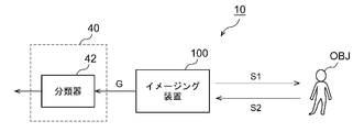
- FIG. 9 is a block diagram of the object identification system 10.
- the object identification system 10 is mounted on a vehicle such as an automobile or a motorcycle, and determines the type (category) of an object OBJ existing around the vehicle.
- the object identification system 10 includes an imaging device 100 and an arithmetic processing device 40. As described above, the imaging apparatus 100 irradiates the object OBJ with the reference light S1 and measures the reflected light S2 to generate the restored image G of the object OBJ.
- the arithmetic processing device 40 processes the output image G of the imaging device 100 and determines the position and type (category) of the object OBJ.
- the classifier 42 of the arithmetic processing device 40 receives the image G as an input and determines the position and type of the object OBJ included in the image G.
- the classifier 42 is implemented based on the model generated by machine learning.
- the algorithm of the classifier 42 is not particularly limited, but YOLO (You Only Look Once), SSD (Single Shot Multi Box Detector), R-CNN (Region-based Convolutional Neural Network), SPPnet (Spatial Pyramid Pooling), Faster R-CNN , DSSD (Deconvolution-SSD), MaskR-CNN, etc. can be adopted, or an algorithm developed in the future can be adopted.
- the imaging device 100 that is, a quantum radar camera
- noise resistance is significantly increased.
- the imaging device 100 that is, a quantum radar camera
- the object OBJ is not affected by rain, snow, or fog.
- the restored image G can be obtained.
- the imaging device 100 by using the imaging device 100, the calculation delay can be reduced. This can provide low latency sensing. Especially in an in-vehicle application, since the object OBJ may move at high speed, the benefit of low-delay sensing is very large.
- FIG. 10 is a block diagram of an automobile including the object identification system 10.
- the automobile 300 includes headlights 302L and 302R.
- the imaging device 100 is built in at least one of the headlights 302L and 302R.
- the headlight 302 is located at the most tip of the vehicle body, and is most advantageous as an installation location of the imaging apparatus 100 in detecting surrounding objects.
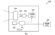
- FIG. 11 is a block diagram showing a vehicular lamp 200 including the object detection system 210.
- the vehicle lamp 200 constitutes a lamp system 310 together with the vehicle-side ECU 304.
- the vehicular lamp 200 includes a light source 202, a lighting circuit 204, and an optical system 206. Further, the vehicle lighting device 200 is provided with an object detection system 210.
- the object detection system 210 corresponds to the above-described object identification system 10, and includes the imaging device 100 and the arithmetic processing device 40.
- Information about the object OBJ detected by the arithmetic processing unit 40 may be used for light distribution control of the vehicular lamp 200.
- the lamp-side ECU 208 generates an appropriate light distribution pattern based on the information on the type and the position of the object OBJ generated by the arithmetic processing device 40.
- the lighting circuit 204 and the optical system 206 operate so as to obtain the light distribution pattern generated by the lamp-side ECU 208.
- Information regarding the object OBJ detected by the arithmetic processing unit 40 may be transmitted to the vehicle-side ECU 304.
- the vehicle-side ECU may perform automatic driving based on this information.
- the method using correlation calculation has been described as the ghost imaging (or single pixel imaging) method, but the image reconstruction method is not limited thereto.
- an analytical method using Fourier transform or Hadamard inverse transform a method for solving an optimization problem such as sparse modeling, and an algorithm using AI/machine learning, The image may be reconstructed.
- the present invention relates to an imaging device.
- OBJ object 10 object identification system 40 arithmetic processing device 42 classifier 100 imaging device 110 illumination device 112 light source 114 patterning device 116 pattern generator 120 photodetector 130 arithmetic processing device 132 pattern generator 134 reconstruction processing unit 200 vehicle lamp 202 Light source 204 Lighting circuit 206 Optical system 300 Automobile 302 Headlight 310 Lighting system 304 Vehicle side ECU
Landscapes
- Engineering & Computer Science (AREA)
- Physics & Mathematics (AREA)
- Mechanical Engineering (AREA)
- Computer Networks & Wireless Communication (AREA)
- General Physics & Mathematics (AREA)
- Radar, Positioning & Navigation (AREA)
- Remote Sensing (AREA)
- Electromagnetism (AREA)
- Image Processing (AREA)
- Lighting Device Outwards From Vehicle And Optical Signal (AREA)
- Optical Radar Systems And Details Thereof (AREA)
- Investigating Or Analysing Materials By Optical Means (AREA)
Abstract
照明装置110は、強度分布が均一である少なくともひとつの基準パターンI0と、強度分布がランダムであり、空間平均強度が既知である複数のランダムパターンI1~IMと、を含む参照光S1を発生する。演算処理装置130は、参照光S1が基準パターンI0であるときに得られる検出強度b0である基準検出強度b0を利用して、参照光S1が複数のランダムパターンI1~IMであるときに得られる複数の検出強度b0~bMの平均である検出強度平均値<b>を計算する。
Description
本発明は、イメージング装置に関する。
自動運転やヘッドランプの配光の自動制御のために、車両の周囲に存在する物体の位置および種類をセンシングする物体識別システムが利用される。物体識別システムは、センサと、センサの出力を解析する演算処理装置を含む。センサは、カメラ、LiDAR(Light Detection and Ranging、Laser Imaging Detection and Ranging)、ミリ波レーダ、超音波ソナーなどの中から、用途、要求精度やコストを考慮して選択される。
イメージング装置(センサ)のひとつとして、ゴーストイメージングの原理を利用したものが知られている。ゴーストイメージングは、参照光の強度分布(パターン)をランダムに切り替えながら物体に照射し、パターンごとに反射光の光検出強度を測定する。光検出強度はある平面にわたるエネルギーあるいは強度の積分値であり、強度分布ではない。そして、対応するパターンと光検出強度との相関計算を行い、物体の復元画像を再構成(reconstruct)する。
本発明者らは、イメージング装置について検討した結果、以下の課題を認識するに至った。ゴーストイメージングにおける相関には、式(1)の相関関数が用いられる。参照光のIrはr番目(r=1,2…,M)の強度分布であり、brはr番目の強度分布を有する参照光を照射したときに得られる検出強度の値である。

図1は、イメージング装置の1フレームのセンシングを示すタイムチャートである。式(1)から分かるように、相関計算には、M回の参照光の照射に対して得られるM個の検出強度b1~bMの平均値<b>が必要である。したがってM回の照射が完了しないと、相関計算を開始できず、時間遅延τが生ずる。車載などのリアルタイム性が要求される用途では、この時間遅延τを極力小さくすることが求められる。
また、物体OBJからの反射光の強度が小さいと、検出強度brが小さくなり、S/N比が低下する。S/N比の低下は、復元される画像の画質の低下をもたらす。
本発明は係る状況においてなされたものであり、そのある態様の例示的な目的のひとつは、画像再構築の時間遅延を短縮可能なイメージング装置の提供にある。また別の態様の例示的な目的のひとつは、画質の低下を抑制可能なイメージング装置の提供にある。
1. 本発明のある態様は、イメージング装置に関する。イメージング装置は、参照光を照射する照明装置と、物体からの反射光を測定する光検出器と、光検出器の出力にもとづく検出強度と参照光の強度分布にもとづいて物体の復元画像を再構成する演算処理装置と、を備える。参照光は、強度分布が均一である少なくともひとつの基準パターンと、複数のランダムパターンと、を含む。各ランダムパターンは、強度分布がランダムであり、空間平均強度が既知である。演算処理装置は、参照光が基準パターンであるときに得られる検出強度である基準検出強度にもとづいて、参照光が複数のランダムパターンであるときに得られる複数の検出強度の平均である検出強度平均値を取得する。
2. 本発明のある態様は、イメージング装置に関する。このイメージング装置は、参照光を照射する照明装置と、物体からの反射光を測定する光検出器と、光検出器の出力にもとづく検出強度と参照光の強度分布にもとづいて、物体の復元画像を再構成する演算処理装置と、を備える。参照光は、ランダムな強度分布を有する複数のランダムパターンを含む。演算処理装置は、あるランダムパターンに対して得られる検出強度と、複数のランダムパターンに対して得られる複数の検出強度の平均である検出強度平均値との差分が所定のしきい値より大きいとき、当該ランダムパターンの照射に関する計算を行い、小さいとき計算を省略する。
3. 本発明のある態様は、ゴーストイメージングにもとづくイメージング装置に関する。イメージング装置は、物体からの反射光を測定する光検出器と、光検出器の出力にもとづく検出強度と参照光の強度分布にもとづいて、物体の復元画像を再構成する演算処理装置と、を備える。参照光は、強度分布が均一である少なくともひとつの基準パターンと、強度分布がランダムであり、空間平均強度が所定値である複数のランダムパターンと、を含む。演算処理装置は、参照光が基準パターンであるときに得られる検出強度である基準検出強度にもとづいて、複数のランダムパターンの空間平均強度を設定する。
本発明のある態様によれば、計算量を減らすことができ、あるいは画質を改善できる。
(実施の形態の概要)
本明細書における「強度分布がランダム」とは、完全なランダムであることを意味するものではなく、ゴーストイメージングにおいて画像を再構築できる程度に、ランダムであればよい。したがって本明細書における「ランダム」は、その中にある程度の規則性を内包することができる。また「ランダム」は、予測不能であることを要求するものではなく、予想可能、再生可能であってもよい。
本明細書における「強度分布がランダム」とは、完全なランダムであることを意味するものではなく、ゴーストイメージングにおいて画像を再構築できる程度に、ランダムであればよい。したがって本明細書における「ランダム」は、その中にある程度の規則性を内包することができる。また「ランダム」は、予測不能であることを要求するものではなく、予想可能、再生可能であってもよい。
1. 本明細書に開示される一実施の形態は、イメージング装置に関する。イメージング装置は、参照光を照射する照明装置と、物体からの反射光を測定する光検出器と、光検出器の出力にもとづく検出強度と参照光の強度分布にもとづいて物体の復元画像を再構成する演算処理装置と、を備える。参照光は、強度分布が均一である少なくともひとつの基準パターンと、複数のランダムパターンと、を含む。各ランダムパターンは、強度分布がランダムであり、空間平均強度が既知である。演算処理装置は、参照光が基準パターンであるときに得られる検出強度である基準検出強度にもとづいて、参照光が複数のランダムパターンであるときに得られる複数の検出強度の平均である検出強度平均値を取得する。
この実施の形態によると、すべてのランダムパターンの照射を待たずに、画像再構築のための計算を開始することができ、計算時間を短縮できる。また、M回のパターン照射に対して得られるデータをすべてメモリに保持する必要がないため、ハードウェアコストを下げることができる場合もある。
基準パターンは、複数のランダムパターンより前に位置してもよい。あるいは、基準パターンは、複数のランダムパターンの先頭部分に挿入されてもよい。
あるランダムパターンに対して得られる検出強度と、検出強度平均値との差分が所定のしきい値より大きいとき、当該ランダムパターンの照射に関する計算を行い、小さいとき計算を省略してもよい。これにより演算量を減らすことができ、あるいは鮮明な画像を得ることができる。
検出強度平均値との差分がしきい値より大きいような検出強度の個数が、所定数に達するまで、複数のランダムパターンの照射を行ってもよい。この場合、鮮明な画像を再構成できる。
複数のランダムパターンの空間平均強度は、基準検出強度にもとづいて設定されてもよい。これにより、検出対象の物体の大きさ、反射率、距離や、参照光の光路の環境に適したセンシングが可能となる。
基準検出強度が小さいほど、複数のランダムパターンの空間平均強度は大きくてもよい。これによりS/N比を高めることができる。
2. 本明細書に開示される一実施の形態もイメージング装置に関する。イメージング装置は、参照光を照射する照明装置と、物体からの反射光を測定する光検出器と、光検出器の出力にもとづく検出強度と参照光の強度分布にもとづいて物体の復元画像を再構成する演算処理装置と、を備える。参照光は、ランダムな強度分布を有する複数のランダムパターンを含む。演算処理装置は、あるランダムパターンに対して得られる検出強度と、複数のランダムパターンに対して得られる複数の検出強度の平均である検出強度平均値との差分がしきい値より大きいとき、当該ランダムパターンの照射に関する計算を行い、小さいとき計算を省略する。
この実施の形態によれば、計算量を減らすことができる。
検出強度平均値との差分がしきい値より大きいような検出強度の個数が、所定数に達するまで、複数のランダムパターンの照射を行ってもよい。この場合、鮮明な画像を再構成できる。
本明細書に開示される一実施の形態は、イメージング装置に関する。イメージング装置は、参照光を照射する照明装置と、物体からの反射光を測定し、検出強度を出力する光検出器と、検出強度と参照光の強度分布にもとづいて、物体の復元画像を再構成する演算処理装置と、を備える。参照光は、強度分布が均一である少なくともひとつの基準パターンと、複数のランダムパターンと、を含む。各ランダムパターンは、強度分布がランダムであり、空間平均強度は所定値である。演算処理装置は、参照光が基準パターンであるときに得られる検出強度である基準検出強度を利用して、参照光が複数のランダムパターンであるときに得られる複数の検出強度の平均である検出強度平均値を計算する。
この実施の形態によると、すべてのランダムパターンの照射を待たずに、画像再構築のための演算処理を開始することができ、計算時間を短縮できる。また、M回のパターン照射に対して得られるデータをすべてメモリに保持する必要がないため、ハードウェアコストを下げることができる場合もある。
基準パターンは、複数のランダムパターンより前に位置してもよい。あるいは、基準パターンは、複数のランダムパターンの先頭部分に挿入されてもよい。
あるランダムパターンに対して得られる検出強度と、検出強度平均値との差分が所定のしきい値より大きいとき、当該ランダムパターンの照射に関する計算を行い、小さいとき計算を省略してもよい。これにより演算量を減らすことができ、あるいは鮮明な画像を得ることができる。
検出強度平均値との差分がしきい値より大きいような検出強度の個数が、所定数に達するまで、複数のランダムパターンの照射を行ってもよい。この場合、鮮明な画像を再構成できる。
複数のランダムパターンの空間平均強度は、基準検出強度にもとづいて設定されてもよい。これにより、検出対象の物体の大きさ、反射率、距離や、参照光の光路の環境に適したセンシングが可能となる。
基準検出強度が小さいほど、複数のランダムパターンの空間平均強度は大きくてもよい。これによりS/N比を高めることができる。
本明細書に開示される一実施の形態もイメージング装置に関する。イメージング装置は、参照光を照射する照明装置と、物体からの反射光を測定し、検出強度を出力する光検出器と、検出強度と参照光の強度分布にもとづいて、物体の復元画像を再構成する演算処理装置と、を備える。参照光は、ランダムな強度分布を有する複数のランダムパターンを含む。演算処理装置は、あるランダムパターンに対して得られる検出強度と、複数のランダムパターンに対して得られる複数の検出強度の平均である検出強度平均値との差分がしきい値より大きいとき、当該ランダムパターンの照射に関する計算を行い、小さいとき計算を省略する。
この実施の形態によれば、計算量を減らすことができる。
検出強度平均値との差分がしきい値より大きいような検出強度の個数が、所定数に達するまで、複数のランダムパターンの照射を行ってもよい。この場合、鮮明な画像を再構成できる。
3. 本明細書に開示される一実施の形態は、イメージング装置に関する。イメージング装置は、参照光を照射する照明装置と、物体からの反射光を測定する光検出器と、光検出器の出力にもとづく検出強度と参照光の強度分布にもとづいて、物体の復元画像を再構成する演算処理装置と、を備える。参照光は、強度分布が均一である少なくともひとつの基準パターンと、複数のランダムパターンと、を含む。各ランダムパターンは、強度分布がランダムであり、空間平均強度が所定値である。演算処理装置は、参照光が基準パターンであるときに得られる検出強度である基準検出強度にもとづいて、複数のランダムパターンの空間平均強度を設定する。
基準検出強度は、物体の大きさ、反射率、イメージング装置と物体との間の伝搬損失に応じて変化する。この実施の形態によれば、検出対象の物体の大きさ、反射率、距離や、参照光の光路の環境に適したセンシングが可能となる。
基準検出強度が小さいほど、複数のランダムパターンの空間平均強度は大きくてもよい。これにより、反射率が低い物体をセンシングする際や、伝搬損失が大きい環境でセンシングする際のS/N比を低下を抑制できる。
演算処理装置は、基準検出強度にもとづいて、参照光が複数のランダムパターンであるときに得られる複数の検出強度の平均である検出強度平均値を取得してもよい。この実施の形態によると、すべてのランダムパターンの照射を待たずに、画像再構築のための計算を開始することができ、計算時間を短縮できる。また、M回のパターン照射に対して得られるデータをすべてメモリに保持する必要がないため、ハードウェアコストを下げることができる場合もある。
あるランダムパターンに対して得られる前記検出強度と、検出強度平均値との差分がしきい値より大きいとき、当該ランダムパターンの照射に関する計算を行い、小さいとき計算を省略してもよい。これにより演算量を減らすことができ、あるいは鮮明な画像を得ることができる。
検出強度平均値との差分がしきい値より大きいような検出強度の個数が、所定数に達するまで、複数のランダムパターンの照射を行ってもよい。この場合、鮮明な画像を再構成できる。
本明細書に開示される一実施の形態もイメージング装置に関する。イメージング装置は、参照光を照射する照明装置と、物体からの反射光を測定し、検出強度を出力する光検出器と、検出強度と参照光の強度分布にもとづいて、物体の復元画像を再構成する演算処理装置と、を備える。参照光は、ランダムな強度分布を有する複数のランダムパターンを含む。演算処理装置は、あるランダムパターンに対して得られる検出強度と、複数のランダムパターンに対して得られる複数の検出強度の平均である検出強度平均値との差分がしきい値より大きいとき、当該ランダムパターンの照射に関する計算を行い、小さいとき計算を省略する。
この実施の形態によれば、計算量を減らすことができる。
検出強度平均値との差分がしきい値より大きいような検出強度の個数が、所定数に達するまで、複数のランダムパターンの照射を行ってもよい。この場合、鮮明な画像を再構成できる。
(実施の形態)
以下、本発明を好適な実施の形態をもとに図面を参照しながら説明する。各図面に示される同一または同等の構成要素、部材、処理には、同一の符号を付するものとし、適宜重複した説明は省略する。また、実施の形態は、発明を限定するものではなく例示であって、実施の形態に記述されるすべての特徴やその組み合わせは、必ずしも発明の本質的なものであるとは限らない。
以下、本発明を好適な実施の形態をもとに図面を参照しながら説明する。各図面に示される同一または同等の構成要素、部材、処理には、同一の符号を付するものとし、適宜重複した説明は省略する。また、実施の形態は、発明を限定するものではなく例示であって、実施の形態に記述されるすべての特徴やその組み合わせは、必ずしも発明の本質的なものであるとは限らない。
図2は、実施の形態に係るイメージング装置100を示す図である。イメージング装置100はゴーストイメージングの原理を用いたシングルピクセルのイメージング装置であり、照明装置110、光検出器120および演算処理装置130を備える。イメージング装置100を、量子レーダカメラとも称する。
照明装置110は、疑似熱光源であり、実質的にランダムとみなしうる強度分布I(x,y)を有する参照光S1を生成し、物体OBJに照射する。物体OBJへの参照光S1の照射は、その強度分布を複数のM回、ランダムに変化させながら行われる。
照明装置110は、光源112、パターニングデバイス114およびパターン発生器132を含む。光源112は、均一な強度分布を有する光S0を生成する。光源112は、レーザや発光ダイオードなどを用いてもよい。参照光S1の波長やスペクトルは特に限定されず、複数のあるいは連続スペクトルを有する白色光であってもよいし、所定の波長を含む単色光であってもよい。参照光S1の波長は、赤外あるいは紫外であってもよい。
パターニングデバイス114は、マトリクス状に配置される複数の画素を有し、複数の画素のオン、オフの組み合わせにもとづいて、光の強度分布Iを空間的に変調可能に構成される。本明細書においてオン状態の画素をオン画素、オフ状態の画素をオフ画素という。なお、以下の説明では理解の容易化のために、各画素は、オンとオフの2値(1,0)のみをとるものとするがその限りでなく、中間的な階調をとってもよい。
パターニングデバイス114としては、反射型のDMD(Digital Micromirror Device)や透過型の液晶デバイスを用いることができる。パターニングデバイス114には、パターン発生器132が発生するパターン信号PTN(画像データ)が与えられている。
パターン発生器132は、参照光S1の強度分布Irを指定するパターン信号PTNrを発生し、時間とともにパターン信号PTNrを切り替える(r=1,2,…M)。
光検出器120は、物体OBJからの反射光を測定し、検出信号Drを出力する。検出信号Drは、強度分布Irを有する参照光を物体OBJに照射したときに、光検出器120に入射する光エネルギー(あるいは強度)の空間的な積分値である。したがって光検出器120は、シングルピクセルの光検出器(フォトディテクタ)を用いることができる。光検出器120からは、複数M通りの強度分布I1~IMそれぞれに対応する複数の検出信号D1~DMが出力される。
演算処理装置130は、パターン発生器132と再構成処理部134を含む。再構成処理部134は、複数の強度分布(ランダムパターンともいう)I1~IMと、複数の検出強度b1~bMの相関計算を行い、物体OBJの復元画像G(x,y)を再構成する。
検出強度b1~bMは、検出信号D1~DMにもとづいている。検出強度と検出信号の関係は、光検出器120の種類や方式などを考慮して定めればよい。
ある強度分布Irの参照光S1を、ある照射期間にわたり照射するとする。また検出信号Drは、ある時刻(あるいは微小時間)の受光量、すなわち瞬時値を表すとする。この場合、照射期間において検出信号Drを複数回サンプリングし、検出強度brを、検出信号Drの全サンプリング値の積分値、平均値あるいは最大値としてもよい。あるいは、全サンプリング値のうちのいくつかを選別し、選別したサンプリング値の積分値や平均値、最大値を用いてもよい。複数のサンプリング値の選別は、たとえば最大値から数えて序列x番目からy番目を抽出してもよいし、任意のしきい値より低いサンプリング値を除外してもよいし、信号変動の大きさが小さい範囲のサンプリング値を抽出してもよい。
光検出器120として、カメラのように露光時間が設定可能なデバイスを用いる場合には、光検出器120の出力Drをそのまま、検出強度brとすることができる。
検出信号Drから検出強度brへの変換は、演算処理装置130が実行してもよいし、演算処理装置130の外部で行ってもよい。
相関には、式(1)の相関関数が用いられる。Irは、r番目の強度分布であり、brはr番目の検出強度の値である。
演算処理装置130は、CPU(Central Processing Unit)やMPU(Micro Processing Unit)、マイコンなどのプロセッサ(ハードウェア)と、プロセッサ(ハードウェア)が実行するソフトウェアプログラムの組み合わせで実装することができる。演算処理装置130は、複数のプロセッサの組み合わせであってもよい。あるいは演算処理装置130はハードウェアのみで構成してもよい。
本実施の形態において、参照光S1は、強度分布がランダムであり、空間平均強度が所定値である複数のランダムパターンI1~IMに加えて、強度分布が均一である少なくともひとつの基準パターンI0と、を含む。以下では基準パターンI0は1個であるとし、全画素がオン(点灯)であるとする。好ましくは基準パターンI0は、複数のランダムパターンI1~IMより前に位置してもよい。
参照光S1の空間平均強度は、パターニングデバイス114の全画素の強度の平均である。パターニングデバイス114の各画素が、オン、オフの2状態で制御される場合、オン画素の強度を1、オフ画素の強度を0に対応付ける。パターニングデバイス114の全画素数をp、オンである画素(オン画素)の個数をqとするとき、空間平均強度は、q/pであり、これを点灯比率ηと称する。言い換えればパターン発生器132は、点灯比率ηがしきい値ηaとなる制約条件のもと、複数のランダムパターンI1~IMを発生する。なお、複数のランダムパターンI1~IMそれぞれの点灯比率η1~ηMが厳密にηaと一致する必要はなく、ある程度の誤差を有していてよい。
なお、基準パターンI0の空間平均強度(点灯比率η0)は1である。
演算処理装置130の再構成処理部134は、参照光S1が基準パターンI0であるときに得られる検出強度である基準検出強度b0を利用して、参照光S1が複数のランダムパターンI1~IMであるときに得られる複数の検出強度b1~brの平均である検出強度平均値<b>を計算する。
基準パターンI0(x,y)が、とある物体に反射して得られる基準検出強度b0は、
b0=ΣxΣyI0(x,y)×f(x,y)
である。f(x,y)は、物体の反射特性や、参照光および反射光の伝送路の特性を表す。
b0=ΣxΣyI0(x,y)×f(x,y)
である。f(x,y)は、物体の反射特性や、参照光および反射光の伝送路の特性を表す。
同じ物体、同じ伝送路を仮定するとき、f(x,y)は同じであるから、ランダムパターンIr(r=1~M)に関しても同じ関係式が成り立つ。
br=ΣxΣy{Ir(x,y)×f(x,y)}
br=ΣxΣy{Ir(x,y)×f(x,y)}
また、M個のランダムパターンI1(x,y)~IM(x,y)の平均的な強度分布<I(x,y)>は均一であり、ηa×I0(x,y)となる。
そうするとM個の検出強度b1~bMの検出強度平均値<b>は、以下の式から計算することができる。
<b>=Σr=1:Mbr/M
=b0×ηa …(2)
<b>=Σr=1:Mbr/M
=b0×ηa …(2)
以上がイメージング装置100の構成である。続いてその動作を説明する。
図3は、イメージング装置100の動作を説明するタイムチャートである。図3では、パターニングデバイス114の全画素数はp=4×4=16画素であり、5個のオン画素が含まれるように、ランダムパターンI1~IMが生成される。つまり点灯比率ηaは5/16に定められる。実際のパターニングデバイス114の画素数pがさらに多くてよいことは言うまでもない。
最初に強度分布が均一である基準パターンI0が照射され、それに対応する基準検出強度b0が測定される。再構成処理部134は、均一照射が完了すると直ちに式(2)にもとづいて、検出強度平均値<b>を算出する。
そして、ランダムパターンI1の照射が終了し、b1が得られると、式(1)のうち、対応する項(cと表記する)を計算し、その値を積算値dとする。
c1=(b1-<b>)I1/M …(3)
d=c1 …(4)
c1=(b1-<b>)I1/M …(3)
d=c1 …(4)
続いて、ランダムパターンI2の照射が終了し、b2が得られると、式(1)のうち、対応する項c2を計算する。そしてc2を、前回得られた値dに加算する。
c2=(b2-<b>)I2/M …(5)
d=d+c2 …(6)
c2=(b2-<b>)I2/M …(5)
d=d+c2 …(6)
一般化すると、r番目のランダムパターンIrの照射に関連して、以下の計算が行われる。
cr=(br-<b>)Ir/M …(7)
d=d+cr …(8)
cr=(br-<b>)Ir/M …(7)
d=d+cr …(8)
この処理は、最後のランダムパターンIMの照射まで繰り返される。
以上がイメージング装置100の動作である。このイメージング装置100によれば、基準パターンI0の照射が終了した段階で、検出強度平均値<b>を算出できる。したがって、それ以降は、新たな検出強度brが得られる度に、相関計算を進めることができる。これにより、M回目のランダムパターンIMの照射の完了後、直ちに、復元画像Gを得ることができ、計算遅延を低減できる。
また、従来の方式では、すべての照射が完了するまで、b1~bMを保持し続けなければならないため、メモリの容量が大きくなる。これに対して本実施の形態では、brは計算完了後破棄することができるため、メモリ容量を削減できる。
続いて、基準パターンの照射に関する変形例を説明する。図4(a)~(c)は、変形例に係るセンシングを説明する図である。
(変形例1)
図3では、1フレームの先頭に、基準パターンI0が位置したがその限りでなく、先頭以外の箇所に挿入してもよい。計算遅延の削減の効果を考慮すると、基準パターンI0はなるべく前の方に挿入した方がよい。たとえば図4(a)に示すように、M=1000である場合に、I100とI101の間に挿入してもよい。この場合であっても、100回目のランダムパターンI100の照射後、基準パターンI0を照射した段階で検出強度平均値<b>が得られる。したがって1000番目のランダムパターンの照射完了を待つ必要がないため、計算遅延を短縮できる。
図3では、1フレームの先頭に、基準パターンI0が位置したがその限りでなく、先頭以外の箇所に挿入してもよい。計算遅延の削減の効果を考慮すると、基準パターンI0はなるべく前の方に挿入した方がよい。たとえば図4(a)に示すように、M=1000である場合に、I100とI101の間に挿入してもよい。この場合であっても、100回目のランダムパターンI100の照射後、基準パターンI0を照射した段階で検出強度平均値<b>が得られる。したがって1000番目のランダムパターンの照射完了を待つ必要がないため、計算遅延を短縮できる。
(変形例2)
図3では、1フレームに、1回の基準パターンI0を挿入したが、その限りでない。図4(b)に示すように、1フレームに複数の基準パターンI0を挿入してもよい。この場合、複数の基準パターンI0に対応して得られる複数の基準検出強度b0の平均値にもとづいて、検出強度平均値<b>を計算してもよい。
図3では、1フレームに、1回の基準パターンI0を挿入したが、その限りでない。図4(b)に示すように、1フレームに複数の基準パターンI0を挿入してもよい。この場合、複数の基準パターンI0に対応して得られる複数の基準検出強度b0の平均値にもとづいて、検出強度平均値<b>を計算してもよい。
(変形例3)
1フレームのセンシングにおいて、連続するK個のランダムパターンごとに1個の基準パターンI0を照射してもよい。この場合、ある基準パターンI0に対応して得られる基準検出強度b0にもとづいて、それに続く(あるいはそれに先行する)K個の検出強度の平均値を計算してもよい。
1フレームのセンシングにおいて、連続するK個のランダムパターンごとに1個の基準パターンI0を照射してもよい。この場合、ある基準パターンI0に対応して得られる基準検出強度b0にもとづいて、それに続く(あるいはそれに先行する)K個の検出強度の平均値を計算してもよい。
(変形例4)
図3の例では、基準パターンI0を、全画素オンとしたが、その限りでない。各画素の強度として中間的な階調を指定できる場合、全画素の強度をηaとしてもよい。この場合、<b>=b0とすることができる。
図3の例では、基準パターンI0を、全画素オンとしたが、その限りでない。各画素の強度として中間的な階調を指定できる場合、全画素の強度をηaとしてもよい。この場合、<b>=b0とすることができる。
続いて、計算時間をより短縮することが可能な変形を説明する。
(変形例5)
変形例5では、あるランダムパターンIrに対して得られる検出強度brと、検出強度平均値<b>との差分|br-<b>|がしきい値δより大きいとき、当該ランダムパターンの照射に関する計算(すなわち項crの計算)を行い、小さいときには、br-<b>≒0、すなわちcr≒0と近似して、その計算を省略する。なおこの変形例において、計算を省略した項は、平均の母集団に含むものとする。
変形例5では、あるランダムパターンIrに対して得られる検出強度brと、検出強度平均値<b>との差分|br-<b>|がしきい値δより大きいとき、当該ランダムパターンの照射に関する計算(すなわち項crの計算)を行い、小さいときには、br-<b>≒0、すなわちcr≒0と近似して、その計算を省略する。なおこの変形例において、計算を省略した項は、平均の母集団に含むものとする。
図5は、変形例5に係るイメージング装置100の動作を説明する図である。b1,b3に関して、<b>との差分|br-<b>|はしきい値δより小さい。したがって、これらに関する項c1,c3の計算は省略され、c1=c3=0とされる。
この変形例5によれば、演算処理装置130における演算量を減らすことができる。
(変形例6)
図6は、変形例6に係るイメージング装置100の動作を説明する図である。変形例6では、変形例5と同様に、あるランダムパターンIrに対して得られる検出強度brと、検出強度平均値<b>との差分|br-<b>|がしきい値δより大きいとき、当該ランダムパターンの照射に関する計算(すなわち項crの計算)を行い、小さいときにはその計算を省略する。変形例5との相違点は、計算を省略した項crは、平均の母集団から除外する点である。つまりM個のランダムパターンI1~IMに対して、実際の平均数mは小さくなる。この変形例6によれば、|br-<b>|が大きな照射を用いて、相関計算を行うため、鮮明な画像を得ることができる。
図6は、変形例6に係るイメージング装置100の動作を説明する図である。変形例6では、変形例5と同様に、あるランダムパターンIrに対して得られる検出強度brと、検出強度平均値<b>との差分|br-<b>|がしきい値δより大きいとき、当該ランダムパターンの照射に関する計算(すなわち項crの計算)を行い、小さいときにはその計算を省略する。変形例5との相違点は、計算を省略した項crは、平均の母集団から除外する点である。つまりM個のランダムパターンI1~IMに対して、実際の平均数mは小さくなる。この変形例6によれば、|br-<b>|が大きな照射を用いて、相関計算を行うため、鮮明な画像を得ることができる。
(変形例7)
変形例7は、変形例6の修正である。変形例6では、m ≪Mとなると、画質が低下する可能性がある。そこで変形例7では、予め準備するランダムパターンの個数M”を、Mより大きくしておき、検出強度平均値<b>との差分がしきい値δより大きいような検出強度brの個数mが、所定数Mに達するまで、複数のランダムパターンの照射を行うこととする。これにより常にM個の検出強度およびランダムパターンにもとづいて相関計算を行うこととなり、鮮明な画像を得ることが可能となる。なお、擬似ランダム信号発生器を用いる場合、予めM”個のパターンを用意する必要はなく、mがMに達するまで、パターンを発生し続ければよい。
変形例7は、変形例6の修正である。変形例6では、m ≪Mとなると、画質が低下する可能性がある。そこで変形例7では、予め準備するランダムパターンの個数M”を、Mより大きくしておき、検出強度平均値<b>との差分がしきい値δより大きいような検出強度brの個数mが、所定数Mに達するまで、複数のランダムパターンの照射を行うこととする。これにより常にM個の検出強度およびランダムパターンにもとづいて相関計算を行うこととなり、鮮明な画像を得ることが可能となる。なお、擬似ランダム信号発生器を用いる場合、予めM”個のパターンを用意する必要はなく、mがMに達するまで、パターンを発生し続ければよい。
図7は、変形例7に係るイメージング装置100の動作を説明する図である。この例では、M=8、M”=19である。この例では、12個目のランダムパターンを照射した時点で、|br-<b>|>δである個数M”が、所定値M=8に到達し、その段階で最終的な復元画像が得られる。この変形例によれば、変形例6に比べてさらに鮮明な画像を得ることが可能となる。
(変形例8)
変形例8において、複数のランダムパターンの空間平均強度、言い換えれば点灯比率ηaは、基準検出強度b0にもとづいて設定される。図8は、変形例8に係るイメージング装置100の動作を説明する図である。この例では、各フレームの点灯比率ηaが、そのフレームの先頭で得られる基準検出強度b0にもとづいて決定される。図8には連続する2フレームが示される。
変形例8において、複数のランダムパターンの空間平均強度、言い換えれば点灯比率ηaは、基準検出強度b0にもとづいて設定される。図8は、変形例8に係るイメージング装置100の動作を説明する図である。この例では、各フレームの点灯比率ηaが、そのフレームの先頭で得られる基準検出強度b0にもとづいて決定される。図8には連続する2フレームが示される。
たとえば、基準検出強度b0が小さいほど、複数のランダムパターンの空間平均強度、すなわち点灯比率ηaを大きくし、反対に基準検出強度b0が大きいほど、点灯比率ηaを小さくする。たとえばηaは、b0に実質的に反比例してもよい。
比較のために、2フレーム目において、1フレーム目と同じ点灯比率ηaを採用したとする。この場合の検出強度b1~bMは、破線で示すように非常に小さくなる。これに対して、基準検出強度b0が小さいフレームでは、ηaを大きくすることで、その後、取得される検出強度b1~bMを大きくすることができる。これによりS/N比の低下を抑制できる。
以上、本発明について、実施の形態をもとに説明した。この実施の形態は例示であり、それらの各構成要素や各処理プロセスの組み合わせにいろいろな変形例が可能なこと、またそうした変形例も本発明の範囲にあることは当業者に理解されるところである。以下、こうした変形例について説明する。
(変形例1)
実施の形態では、照明装置110を、光源112とパターニングデバイス114の組み合わせで構成したがその限りでない。たとえば照明装置110は、マトリクス状に配置される複数の半導体光源(LED(発光ダイオード)やLD(レーザダイオード))のアレイで構成し、個々の半導体光源のオン、オフ(あるいは輝度)を制御可能に構成してもよい。
実施の形態では、照明装置110を、光源112とパターニングデバイス114の組み合わせで構成したがその限りでない。たとえば照明装置110は、マトリクス状に配置される複数の半導体光源(LED(発光ダイオード)やLD(レーザダイオード))のアレイで構成し、個々の半導体光源のオン、オフ(あるいは輝度)を制御可能に構成してもよい。
(用途)
続いてイメージング装置100の用途を説明する。図9は、物体識別システム10のブロック図である。この物体識別システム10は、自動車やバイクなどの車両に搭載され、車両の周囲に存在する物体OBJの種類(カテゴリ)を判定する。
続いてイメージング装置100の用途を説明する。図9は、物体識別システム10のブロック図である。この物体識別システム10は、自動車やバイクなどの車両に搭載され、車両の周囲に存在する物体OBJの種類(カテゴリ)を判定する。
物体識別システム10は、イメージング装置100と、演算処理装置40を備える。イメージング装置100は、上述のように、物体OBJに参照光S1を照射し、反射光S2を測定することにより、物体OBJの復元画像Gを生成する。
演算処理装置40は、イメージング装置100の出力画像Gを処理し、物体OBJの位置および種類(カテゴリ)を判定する。
演算処理装置40の分類器42は、画像Gを入力として受け、それに含まれる物体OBJの位置および種類を判定する。分類器42は、機械学習によって生成されたモデルにもとづいて実装される。分類器42のアルゴリズムは特に限定されないが、YOLO(You Only Look Once)とSSD(Single Shot MultiBox Detector)、R-CNN(Region-based Convolutional Neural Network)、SPPnet(Spatial Pyramid Pooling)、Faster R-CNN、DSSD(Deconvolution -SSD)、Mask R-CNNなどを採用することができ、あるいは、将来開発されるアルゴリズムを採用できる。
以上が物体識別システム10の構成である。物体識別システム10のセンサとして、イメージング装置100を用いることで、以下の利点を得ることができる。
イメージング装置100すなわち量子レーダカメラを用いることで、ノイズ耐性が格段に高まる。たとえば、降雨時、降雪時、あるいは霧の中を走行する場合、肉眼では物体OBJを認識しにくいが、イメージング装置100を用いることで、雨、雪、霧の影響を受けずに、物体OBJの復元画像Gを得ることができる。
また、イメージング装置100を用いることで、計算遅延を小さくできる。これにより低遅延のセンシングを提供できる。特に車載用途では物体OBJが高速に移動するケースがあるため、低遅延のセンシングがもたらす恩恵は、非常に大きい。
図10は、物体識別システム10を備える自動車のブロック図である。自動車300は、前照灯302L,302Rを備える。イメージング装置100は、前照灯302L,302Rの少なくとも一方に内蔵される。前照灯302は、車体の最も先端に位置しており、周囲の物体を検出する上で、イメージング装置100の設置箇所として最も有利である。
図11は、物体検出システム210を備える車両用灯具200を示すブロック図である。車両用灯具200は、車両側ECU304とともに灯具システム310を構成する。車両用灯具200は、光源202、点灯回路204、光学系206を備える。さらに車両用灯具200には、物体検出システム210が設けられる。物体検出システム210は、上述の物体識別システム10に対応しており、イメージング装置100および演算処理装置40を含む。
演算処理装置40が検出した物体OBJに関する情報は、車両用灯具200の配光制御に利用してもよい。具体的には、灯具側ECU208は、演算処理装置40が生成する物体OBJの種類とその位置に関する情報にもとづいて、適切な配光パターンを生成する。点灯回路204および光学系206は、灯具側ECU208が生成した配光パターンが得られるように動作する。
また演算処理装置40が検出した物体OBJに関する情報は、車両側ECU304に送信してもよい。車両側ECUは、この情報にもとづいて、自動運転を行ってもよい。
実施の形態において、ゴーストイメージング(あるいはシングルピクセルイメージング)の手法として、相関計算を用いた手法を説明したが、画像の再構築の手法はそれに限定されない。いくつかの実施の形態では、相関計算に変えて、フーリエ変換やアダマール逆変換を使用した解析的手法や、スパースモデリングなどの最適化問題を解く手法、およびAI・機械学習を利用したアルゴリズムによって、画像を再構築してもよい。
実施の形態にもとづき、具体的な語句を用いて本発明を説明したが、実施の形態は、本発明の原理、応用の一側面を示しているにすぎず、実施の形態には、請求の範囲に規定された本発明の思想を逸脱しない範囲において、多くの変形例や配置の変更が認められる。
本発明は、イメージング装置に関する。
OBJ 物体
10 物体識別システム
40 演算処理装置
42 分類器
100 イメージング装置
110 照明装置
112 光源
114 パターニングデバイス
116 パターン発生器
120 光検出器
130 演算処理装置
132 パターン発生器
134 再構成処理部
200 車両用灯具
202 光源
204 点灯回路
206 光学系
300 自動車
302 前照灯
310 灯具システム
304 車両側ECU
10 物体識別システム
40 演算処理装置
42 分類器
100 イメージング装置
110 照明装置
112 光源
114 パターニングデバイス
116 パターン発生器
120 光検出器
130 演算処理装置
132 パターン発生器
134 再構成処理部
200 車両用灯具
202 光源
204 点灯回路
206 光学系
300 自動車
302 前照灯
310 灯具システム
304 車両側ECU
Claims (28)
- 参照光を照射する照明装置と、
物体からの反射光を測定する光検出器と、
前記光検出器の出力にもとづく検出強度と前記参照光の強度分布にもとづいて、前記物体の復元画像を再構成する演算処理装置と、
を備え、
前記参照光は、強度分布が均一である少なくともひとつの基準パターンと、強度分布がランダムであり、空間平均強度が既知である複数のランダムパターンと、を含み、
前記演算処理装置は、前記参照光が前記基準パターンであるときに得られる前記検出強度である基準検出強度を利用して、前記参照光が前記複数のランダムパターンであるときに得られる複数の前記検出強度の平均である検出強度平均値を取得することを特徴とするイメージング装置。 - 前記基準パターンは、前記複数のランダムパターンより前に位置することを特徴とする請求項1に記載のイメージング装置。
- あるランダムパターンに対して得られる前記検出強度と、前記検出強度平均値との差分がしきい値より大きいとき、当該ランダムパターンの照射に関する計算を行い、小さいとき計算を省略することを特徴とする請求項1または2に記載のイメージング装置。
- 前記検出強度平均値との差分がしきい値より大きいような前記検出強度の個数が、所定数に達するまで、前記複数のランダムパターンの照射を行うことを特徴とする請求項3に記載のイメージング装置。
- 前記複数のランダムパターンの前記空間平均強度は、前記基準検出強度にもとづいて設定されることを特徴とする請求項2に記載のイメージング装置。
- 前記基準検出強度が小さいほど、前記複数のランダムパターンの前記空間平均強度は大きいことを特徴とする請求項5に記載のイメージング装置。
- 請求項1から6のいずれかに記載のイメージング装置を備えることを特徴とする車両用灯具。
- 請求項1から6のいずれかに記載のイメージング装置を備えることを特徴とする自動車。
- イメージング装置に用いられる演算処理装置であって、
前記イメージング装置は、
参照光を照射する照明装置と、
物体からの反射光を測定する光検出器と、
前記参照光の強度分布を制御するとともに、前記光検出器の出力にもとづく検出強度と前記参照光の強度分布にもとづいて、前記物体の復元画像を再構成可能な演算処理装置と、
を備えるものであり、
前記演算処理装置は、
前記参照光の強度分布を、(i)均一な基準パターンと、(ii)強度分布がランダムであり、空間平均強度が既知である複数のランダムパターンとで切り替え、
前記参照光が前記基準パターンであるときに得られる前記検出強度である基準検出強度を利用して、前記参照光が前記複数のランダムパターンであるときに得られる複数の前記検出強度の平均である検出強度平均値を取得することを特徴とする演算処理装置。 - 参照光を物体に照射するステップと、
前記物体からの反射光を測定し、検出強度を生成するステップと、
前記検出強度と前記参照光の強度分布にもとづいて、前記物体の復元画像を再構成するステップと、
を備え、
前記参照光は、強度分布が均一である少なくともひとつの基準パターンと、強度分布がランダムであり、空間平均強度が既知である複数のランダムパターンと、を含み、
前記参照光が前記基準パターンであるときに得られる前記検出強度である基準検出強度を利用して、前記参照光が前記複数のランダムパターンであるときに得られる複数の前記検出強度の平均である検出強度平均値を取得することを特徴とするセンシング方法。 - ランダムな強度分布を有する複数のランダムパターンを含む参照光を照射する照明装置と、
物体からの反射光を測定する光検出器と、
前記光検出器の出力にもとづく検出強度と前記参照光の強度分布にもとづいて、前記物体の復元画像を再構成する演算処理装置と、
を備え、
前記演算処理装置は、あるランダムパターンに対して得られる前記検出強度と、前記複数のランダムパターンに対して得られる複数の検出強度の平均である検出強度平均値との差分がしきい値より大きいとき、当該ランダムパターンの照射に関する計算を行い、小さいとき計算を省略することを特徴とするイメージング装置。 - 前記検出強度平均値との差分がしきい値より大きいような前記検出強度の個数が、所定数に達するまで、前記複数のランダムパターンの照射を行うことを特徴とする請求項11に記載のイメージング装置。
- 前記参照光は、均一な基準パターンをさらに含み、
前記複数のランダムパターンの空間平均強度は所定値であり、
前記演算処理装置は、前記参照光が前記基準パターンであるときに得られる前記検出強度である基準検出強度を利用して、前記検出強度平均値を計算することを特徴とする請求項11または12に記載のイメージング装置。 - 請求項11または12に記載のイメージング装置を備えることを特徴とする車両用灯具。
- 請求項11から13のいずれかに記載のイメージング装置を備えることを特徴とする車両。
- イメージング装置に用いられる演算処理装置であって、
前記イメージング装置は、
ランダムな強度分布を有する複数のランダムパターンを含む参照光を照射する照明装置と、
物体からの反射光を測定する光検出器と、
前記参照光の強度分布を制御するとともに、前記光検出器の出力にもとづく検出強度と前記参照光の強度分布にもとづいて、前記物体の復元画像を再構成する演算処理装置と、
を備え、
前記演算処理装置は、あるランダムパターンに対して得られる前記検出強度と、前記複数のランダムパターンに対して得られる複数の検出強度の平均である検出強度平均値との差分がしきい値より大きいとき、当該ランダムパターンの照射に関する計算を行い、小さいとき計算を省略することを特徴とする演算処理装置。 - 前記検出強度平均値との差分がしきい値より大きいような前記検出強度の個数が、所定数に達するまで、前記複数のランダムパターンの照射を行うことを特徴とする請求項16に記載の演算処理装置。
- 前記複数のランダムパターンの空間平均強度は所定値であり、
前記演算処理装置は、前記参照光を、均一な基準パターンに切り替え可能であり、
前記演算処理装置は、前記参照光が前記基準パターンであるときに得られる前記検出強度である基準検出強度にもとづいて、前記検出強度平均値を取得することを特徴とする請求項16または17に記載の演算処理装置。 - ランダムな強度分布を有する複数のランダムパターンを含む参照光を物体に照射するステップと、
前記物体からの反射光を測定し、検出強度を生成するステップと、
前記検出強度と前記参照光の強度分布にもとづいて、前記物体の復元画像を再構成するステップと、
を備え、
あるランダムパターンに対して得られる前記検出強度と、前記複数のランダムパターンに対して得られる複数の検出強度の平均である検出強度平均値との差分がしきい値より大きいとき、当該ランダムパターンの照射に関する計算を行い、小さいとき計算を省略することを特徴とする方法。 - 参照光を照射する照明装置と、
物体からの反射光を測定する光検出器と、
前記光検出器の出力にもとづく検出強度と前記参照光の強度分布にもとづいて、前記物体の復元画像を再構成する演算処理装置と、
を備え、
前記参照光は、強度分布が均一である少なくともひとつの基準パターンと、強度分布がランダムであり、空間平均強度が所定値である複数のランダムパターンと、を含み、
前記演算処理装置は、前記参照光が前記基準パターンであるときに得られる前記検出強度である基準検出強度にもとづいて、前記複数のランダムパターンの空間平均強度を設定することを特徴とするイメージング装置。 - 前記基準検出強度が小さいほど、前記複数のランダムパターンの前記空間平均強度は大きいことを特徴とする請求項20に記載のイメージング装置。
- 前記演算処理装置は、前記基準検出強度にもとづいて、前記参照光が前記複数のランダムパターンであるときに得られる複数の前記検出強度の平均である検出強度平均値を取得することを特徴とする請求項20または21に記載のイメージング装置。
- あるランダムパターンに対して得られる前記検出強度と、前記検出強度平均値との差分がしきい値より大きいとき、当該ランダムパターンの照射に関する計算を行い、小さいとき計算を省略することを特徴とする請求項22に記載のイメージング装置。
- 前記検出強度平均値との差分がしきい値より大きいような前記検出強度の個数が、所定数に達するまで、前記複数のランダムパターンの照射を行うことを特徴とする請求項23に記載のイメージング装置。
- 請求項20から24のいずれかに記載のイメージング装置を備えることを特徴とする車両用灯具。
- 請求項20から24のいずれかに記載のイメージング装置を備えることを特徴とする車両。
- イメージング装置に用いられる演算処理装置であって、
前記イメージング装置は、
参照光を照射する照明装置と、
物体からの反射光を測定し、検出強度を出力する光検出器と、
前記参照光の強度分布を制御するとともに、前記検出強度と前記参照光の強度分布にもとづいて、前記物体の復元画像を再構成可能な演算処理装置と、
を備えるものであり、
前記演算処理装置は、
前記参照光の強度分布を、(i)均一な基準パターンと、(ii)強度分布がランダムであり、空間平均強度が所定値である複数のランダムパターンとで切り替え、
前記参照光が前記基準パターンであるときに得られる前記検出強度である基準検出強度にもとづいて、前記複数のランダムパターンの前記空間平均強度を設定することを特徴とする演算処理装置。 - 参照光を物体に照射するステップと、
前記物体からの反射光を測定し、検出強度を生成するステップと、
前記検出強度と前記参照光の強度分布にもとづいて、前記物体の復元画像を再構成するステップと、
を備え、
前記参照光は、強度分布が均一である少なくともひとつの基準パターンと、強度分布がランダムであり、空間平均強度が所定値である複数のランダムパターンと、を含み、
前記参照光が前記基準パターンであるときに得られる前記検出強度である基準検出強度にもとづいて、前記複数のランダムパターンの空間平均強度が設定されることを特徴とするセンシング方法。
Priority Applications (2)
| Application Number | Priority Date | Filing Date | Title |
|---|---|---|---|
| CN201980089145.4A CN113302520B (zh) | 2019-01-16 | 2019-12-26 | 成像装置、其运算处理装置、车辆用灯具、车辆、感测方法 |
| JP2020566185A JP7395511B2 (ja) | 2019-01-16 | 2019-12-26 | イメージング装置、その演算処理装置、車両用灯具、車両、センシング方法 |
Applications Claiming Priority (6)
| Application Number | Priority Date | Filing Date | Title |
|---|---|---|---|
| JP2019005430 | 2019-01-16 | ||
| JP2019-005428 | 2019-01-16 | ||
| JP2019005429 | 2019-01-16 | ||
| JP2019-005430 | 2019-01-16 | ||
| JP2019005428 | 2019-01-16 | ||
| JP2019-005429 | 2019-01-16 |
Publications (1)
| Publication Number | Publication Date |
|---|---|
| WO2020149139A1 true WO2020149139A1 (ja) | 2020-07-23 |
Family
ID=71613299
Family Applications (1)
| Application Number | Title | Priority Date | Filing Date |
|---|---|---|---|
| PCT/JP2019/051192 Ceased WO2020149139A1 (ja) | 2019-01-16 | 2019-12-26 | イメージング装置、その演算処理装置、車両用灯具、車両、センシング方法 |
Country Status (3)
| Country | Link |
|---|---|
| JP (1) | JP7395511B2 (ja) |
| CN (1) | CN113302520B (ja) |
| WO (1) | WO2020149139A1 (ja) |
Cited By (1)
| Publication number | Priority date | Publication date | Assignee | Title |
|---|---|---|---|---|
| JPWO2022044961A1 (ja) * | 2020-08-28 | 2022-03-03 |
Citations (8)
| Publication number | Priority date | Publication date | Assignee | Title |
|---|---|---|---|---|
| JPH0112673B2 (ja) * | 1983-06-01 | 1989-03-01 | Sumitomo Beekuraito Kk | |
| JPH11194275A (ja) * | 1997-10-22 | 1999-07-21 | Max Planck Ges Foerderung Wissenschaft Ev | プログラム可能であり空間的に光変調された顕微鏡および顕微鏡による方法 |
| US20130088726A1 (en) * | 2011-10-07 | 2013-04-11 | Vivek K. Goyal | Method and Apparatus to Determine Depth Information For A Scene of Interest |
| JP2014531032A (ja) * | 2011-10-25 | 2014-11-20 | センター フォー スペース サイエンス アンド アプライド リサーチ、 チャイニーズ アカデミー オブ サイエンスズCenter For Space Science And Applied Research, Chinese Academy Of Sciences | 時間分解単一光子又は極微弱光多次元イメージングスペクトルシステム及び方法 |
| JP2017009350A (ja) * | 2015-06-18 | 2017-01-12 | コニカミノルタ株式会社 | 発光分布測定装置 |
| JP2017525952A (ja) * | 2014-07-31 | 2017-09-07 | レイセオン カンパニー | 線形モード計算センシングレーザーレーダー |
| CN108363069A (zh) * | 2018-01-18 | 2018-08-03 | 中国科学院理化技术研究所 | 基于分布式半导体激光阵列的关联成像装置及方法 |
| JP2018156862A (ja) * | 2017-03-17 | 2018-10-04 | トヨタ自動車株式会社 | 車両用前照灯装置 |
Family Cites Families (21)
| Publication number | Priority date | Publication date | Assignee | Title |
|---|---|---|---|---|
| JP4364104B2 (ja) * | 2004-11-08 | 2009-11-11 | 勝 内田 | 山芋類の栽培方法 |
| WO2007043036A1 (en) * | 2005-10-11 | 2007-04-19 | Prime Sense Ltd. | Method and system for object reconstruction |
| TW200705088A (en) * | 2005-06-03 | 2007-02-01 | Kuraray Co | Rear projection display apparatus |
| JP4577126B2 (ja) * | 2005-07-08 | 2010-11-10 | オムロン株式会社 | ステレオ対応づけのための投光パターンの生成装置及び生成方法 |
| JP2008016101A (ja) * | 2006-07-04 | 2008-01-24 | Sharp Corp | 情報再生方法およびホログラフィー装置 |
| JP2010019984A (ja) * | 2008-07-09 | 2010-01-28 | Sony Corp | 再生装置、再生方法 |
| JP2012008261A (ja) * | 2010-06-23 | 2012-01-12 | Hamamatsu Photonics Kk | 画像生成装置 |
| CN103857981B (zh) * | 2011-10-11 | 2017-05-10 | 株式会社尼康 | 形状测定装置、构造物制造系统、形状测定方法、构造物制造方法 |
| JP6070306B2 (ja) * | 2013-03-14 | 2017-02-01 | オムロン株式会社 | 画像処理装置、オブジェクト検出方法、およびオブジェクト検出プログラム |
| EP3019824B1 (en) * | 2013-07-09 | 2018-01-10 | Xenomatix NV | Surround sensing system |
| JP6348349B2 (ja) * | 2014-06-20 | 2018-06-27 | 大塚電子株式会社 | 動的光散乱測定装置及び動的光散乱測定方法 |
| CN105627952B (zh) * | 2015-12-25 | 2018-02-13 | 暨南大学 | 一种使用单像素探测器的物体三维形貌测量方法和装置 |
| JP6795993B2 (ja) * | 2016-02-18 | 2020-12-02 | 株式会社ミツトヨ | 形状測定システム、形状測定装置及び形状測定方法 |
| EP3433578B8 (en) * | 2016-03-21 | 2021-06-16 | Velodyne Lidar USA, Inc. | Lidar based 3-d imaging with varying illumination intensity |
| CN108027238B (zh) * | 2016-09-01 | 2022-06-14 | 索尼半导体解决方案公司 | 成像装置 |
| KR102679093B1 (ko) * | 2016-09-23 | 2024-06-28 | 엘지디스플레이 주식회사 | 터치스크린 내장형 유기발광표시패널 및 유기발광표시장치 |
| JP6765687B2 (ja) * | 2016-12-29 | 2020-10-07 | 国立大学法人 東京大学 | イメージング装置及び方法 |
| US10445893B2 (en) * | 2017-03-10 | 2019-10-15 | Microsoft Technology Licensing, Llc | Dot-based time of flight |
| US10527711B2 (en) * | 2017-07-10 | 2020-01-07 | Aurora Flight Sciences Corporation | Laser speckle system and method for an aircraft |
| JP6412673B1 (ja) * | 2017-07-21 | 2018-10-24 | 学校法人玉川学園 | 画像処理装置及び方法、並びに、プログラム |
| GB2568751A (en) * | 2017-11-28 | 2019-05-29 | Jaguar Land Rover Ltd | Terrain analysis apparatus and method |
-
2019
- 2019-12-26 WO PCT/JP2019/051192 patent/WO2020149139A1/ja not_active Ceased
- 2019-12-26 CN CN201980089145.4A patent/CN113302520B/zh active Active
- 2019-12-26 JP JP2020566185A patent/JP7395511B2/ja active Active
Patent Citations (8)
| Publication number | Priority date | Publication date | Assignee | Title |
|---|---|---|---|---|
| JPH0112673B2 (ja) * | 1983-06-01 | 1989-03-01 | Sumitomo Beekuraito Kk | |
| JPH11194275A (ja) * | 1997-10-22 | 1999-07-21 | Max Planck Ges Foerderung Wissenschaft Ev | プログラム可能であり空間的に光変調された顕微鏡および顕微鏡による方法 |
| US20130088726A1 (en) * | 2011-10-07 | 2013-04-11 | Vivek K. Goyal | Method and Apparatus to Determine Depth Information For A Scene of Interest |
| JP2014531032A (ja) * | 2011-10-25 | 2014-11-20 | センター フォー スペース サイエンス アンド アプライド リサーチ、 チャイニーズ アカデミー オブ サイエンスズCenter For Space Science And Applied Research, Chinese Academy Of Sciences | 時間分解単一光子又は極微弱光多次元イメージングスペクトルシステム及び方法 |
| JP2017525952A (ja) * | 2014-07-31 | 2017-09-07 | レイセオン カンパニー | 線形モード計算センシングレーザーレーダー |
| JP2017009350A (ja) * | 2015-06-18 | 2017-01-12 | コニカミノルタ株式会社 | 発光分布測定装置 |
| JP2018156862A (ja) * | 2017-03-17 | 2018-10-04 | トヨタ自動車株式会社 | 車両用前照灯装置 |
| CN108363069A (zh) * | 2018-01-18 | 2018-08-03 | 中国科学院理化技术研究所 | 基于分布式半导体激光阵列的关联成像装置及方法 |
Non-Patent Citations (1)
| Title |
|---|
| COLACO, ANDREA ET AL.: "Compressive Depth Map Acquisition Using a Single Photon-Counting Detector: Parametric Signal Processing Meets Sparsity", IEEE CONFERENCE ON COMPUTER VISION AND PATTERN RECOGNITION, 26 July 2012 (2012-07-26), pages 96 - 102, XP032232062, Retrieved from the Internet <URL:https://ieeexplore.ieee.org/stamp/stamp.jsp?tp=&arnumber=6247663> * |
Cited By (1)
| Publication number | Priority date | Publication date | Assignee | Title |
|---|---|---|---|---|
| JPWO2022044961A1 (ja) * | 2020-08-28 | 2022-03-03 |
Also Published As
| Publication number | Publication date |
|---|---|
| JP7395511B2 (ja) | 2023-12-11 |
| JPWO2020149139A1 (ja) | 2021-11-25 |
| CN113302520A (zh) | 2021-08-24 |
| CN113302520B (zh) | 2024-07-02 |
Similar Documents
| Publication | Publication Date | Title |
|---|---|---|
| JP7463297B2 (ja) | 車載用イメージング装置、車両用灯具、自動車 | |
| JP7408572B2 (ja) | 車両用灯具および車両 | |
| US12003839B2 (en) | Imaging apparatus using ghost imaging | |
| US12047667B2 (en) | Imaging device | |
| US12108164B2 (en) | Imaging apparatus | |
| WO2022270476A1 (ja) | イメージング装置および車両用灯具、車両 | |
| JP7395511B2 (ja) | イメージング装置、その演算処理装置、車両用灯具、車両、センシング方法 | |
| JP7608353B2 (ja) | イメージング装置、車両用灯具、車両、イメージング方法 | |
| JP2020106376A (ja) | アクティブセンサ、物体識別システム、車両、車両用灯具 | |
| WO2022091972A1 (ja) | イメージング装置および車両用灯具、車両 | |
| WO2023085328A1 (ja) | イメージング装置およびイメージング方法、車両用灯具、車両 | |
| US12205335B2 (en) | Imaging apparatus and imaging method | |
| JP7524207B2 (ja) | イメージング装置、車両用灯具、車両、イメージング方法 | |
| WO2023085329A1 (ja) | イメージングシステム、センサユニット、車両用灯具、車両 | |
| WO2023074759A1 (ja) | イメージング装置、車両用灯具、車両 | |
| EP4382969A1 (en) | Gated camera, vehicular sensing system, and vehicular lamp | |
| WO2022102775A1 (ja) | センシング装置、車両用灯具、車両 | |
| CN116457700A (zh) | 感测装置、车辆用灯具、车辆 |
Legal Events
| Date | Code | Title | Description |
|---|---|---|---|
| 121 | Ep: the epo has been informed by wipo that ep was designated in this application |
Ref document number: 19910054 Country of ref document: EP Kind code of ref document: A1 |
|
| ENP | Entry into the national phase |
Ref document number: 2020566185 Country of ref document: JP Kind code of ref document: A |
|
| NENP | Non-entry into the national phase |
Ref country code: DE |
|
| 122 | Ep: pct application non-entry in european phase |
Ref document number: 19910054 Country of ref document: EP Kind code of ref document: A1 |