WO2020149108A1 - 光学機器用アクチュエータおよびこれを備えたレンズ鏡筒 - Google Patents
光学機器用アクチュエータおよびこれを備えたレンズ鏡筒 Download PDFInfo
- Publication number
- WO2020149108A1 WO2020149108A1 PCT/JP2019/050347 JP2019050347W WO2020149108A1 WO 2020149108 A1 WO2020149108 A1 WO 2020149108A1 JP 2019050347 W JP2019050347 W JP 2019050347W WO 2020149108 A1 WO2020149108 A1 WO 2020149108A1
- Authority
- WO
- WIPO (PCT)
- Prior art keywords
- vibration
- actuator
- guide
- guide shaft
- frame
- Prior art date
- Legal status (The legal status is an assumption and is not a legal conclusion. Google has not performed a legal analysis and makes no representation as to the accuracy of the status listed.)
- Ceased
Links
Images


Classifications
-
- G—PHYSICS
- G02—OPTICS
- G02B—OPTICAL ELEMENTS, SYSTEMS OR APPARATUS
- G02B7/00—Mountings, adjusting means, or light-tight connections, for optical elements
- G02B7/02—Mountings, adjusting means, or light-tight connections, for optical elements for lenses
- G02B7/04—Mountings, adjusting means, or light-tight connections, for optical elements for lenses with mechanism for focusing or varying magnification
- G02B7/08—Mountings, adjusting means, or light-tight connections, for optical elements for lenses with mechanism for focusing or varying magnification adapted to co-operate with a remote control mechanism
-
- G—PHYSICS
- G02—OPTICS
- G02B—OPTICAL ELEMENTS, SYSTEMS OR APPARATUS
- G02B7/00—Mountings, adjusting means, or light-tight connections, for optical elements
- G02B7/02—Mountings, adjusting means, or light-tight connections, for optical elements for lenses
- G02B7/04—Mountings, adjusting means, or light-tight connections, for optical elements for lenses with mechanism for focusing or varying magnification
-
- G—PHYSICS
- G02—OPTICS
- G02B—OPTICAL ELEMENTS, SYSTEMS OR APPARATUS
- G02B7/00—Mountings, adjusting means, or light-tight connections, for optical elements
- G02B7/02—Mountings, adjusting means, or light-tight connections, for optical elements for lenses
- G02B7/021—Mountings, adjusting means, or light-tight connections, for optical elements for lenses for more than one lens
-
- G—PHYSICS
- G03—PHOTOGRAPHY; CINEMATOGRAPHY; ANALOGOUS TECHNIQUES USING WAVES OTHER THAN OPTICAL WAVES; ELECTROGRAPHY; HOLOGRAPHY
- G03B—APPARATUS OR ARRANGEMENTS FOR TAKING PHOTOGRAPHS OR FOR PROJECTING OR VIEWING THEM; APPARATUS OR ARRANGEMENTS EMPLOYING ANALOGOUS TECHNIQUES USING WAVES OTHER THAN OPTICAL WAVES; ACCESSORIES THEREFOR
- G03B5/00—Adjustment of optical system relative to image or object surface other than for focusing
-
- H—ELECTRICITY
- H02—GENERATION; CONVERSION OR DISTRIBUTION OF ELECTRIC POWER
- H02N—ELECTRIC MACHINES NOT OTHERWISE PROVIDED FOR
- H02N2/00—Electric machines in general using piezoelectric effect, electrostriction or magnetostriction
- H02N2/02—Electric machines in general using piezoelectric effect, electrostriction or magnetostriction producing linear motion, e.g. actuators; Linear positioners ; Linear motors
- H02N2/021—Electric machines in general using piezoelectric effect, electrostriction or magnetostriction producing linear motion, e.g. actuators; Linear positioners ; Linear motors using intermittent driving, e.g. step motors, piezoleg motors
- H02N2/025—Inertial sliding motors
-
- H—ELECTRICITY
- H02—GENERATION; CONVERSION OR DISTRIBUTION OF ELECTRIC POWER
- H02N—ELECTRIC MACHINES NOT OTHERWISE PROVIDED FOR
- H02N2/00—Electric machines in general using piezoelectric effect, electrostriction or magnetostriction
- H02N2/10—Electric machines in general using piezoelectric effect, electrostriction or magnetostriction producing rotary motion, e.g. rotary motors
- H02N2/103—Electric machines in general using piezoelectric effect, electrostriction or magnetostriction producing rotary motion, e.g. rotary motors by pressing one or more vibrators against the rotor
-
- G—PHYSICS
- G03—PHOTOGRAPHY; CINEMATOGRAPHY; ANALOGOUS TECHNIQUES USING WAVES OTHER THAN OPTICAL WAVES; ELECTROGRAPHY; HOLOGRAPHY
- G03B—APPARATUS OR ARRANGEMENTS FOR TAKING PHOTOGRAPHS OR FOR PROJECTING OR VIEWING THEM; APPARATUS OR ARRANGEMENTS EMPLOYING ANALOGOUS TECHNIQUES USING WAVES OTHER THAN OPTICAL WAVES; ACCESSORIES THEREFOR
- G03B2205/00—Adjustment of optical system relative to image or object surface other than for focusing
- G03B2205/0046—Movement of one or more optical elements for zooming
-
- G—PHYSICS
- G03—PHOTOGRAPHY; CINEMATOGRAPHY; ANALOGOUS TECHNIQUES USING WAVES OTHER THAN OPTICAL WAVES; ELECTROGRAPHY; HOLOGRAPHY
- G03B—APPARATUS OR ARRANGEMENTS FOR TAKING PHOTOGRAPHS OR FOR PROJECTING OR VIEWING THEM; APPARATUS OR ARRANGEMENTS EMPLOYING ANALOGOUS TECHNIQUES USING WAVES OTHER THAN OPTICAL WAVES; ACCESSORIES THEREFOR
- G03B2205/00—Adjustment of optical system relative to image or object surface other than for focusing
- G03B2205/0053—Driving means for the movement of one or more optical element
- G03B2205/0061—Driving means for the movement of one or more optical element using piezoelectric actuators
Definitions
- the present disclosure relates to an actuator for an optical device that drives an optical device such as a lens back and forth along an optical axis direction, and a lens barrel including the actuator.
- a vibration actuator for exciting the guide shaft such as SIDM (Smooth Impact Drive Mechanism) capable of high-speed response
- SIDM Smooth Impact Drive Mechanism
- An external force mitigating support part attached to the piezoelectric element to mitigate the influence of the external force acting on the drive part when the drive part including the support shaft and the drive part including the drive shaft receives an external force in a direction different from the axial direction.
- a drive device including (a spring or the like) is disclosed.
- the configuration of the conventional drive device has the following problems. That is, in the configuration of the drive device disclosed in the above publication, even when an external force is applied to the drive shaft or the like in a direction different from the axial direction, the influence of the external force can be mitigated by the external force mitigation support portion such as a spring.
- the conventional structure employs a so-called floating structure in which the first end side of the drive shaft is supported so as to be movable in the axial direction. That is, in the conventional configuration, the end of the guide shaft that guides the lens in the optical axis direction is supported in an unstable state. For this reason, when the drive device is mounted on, for example, a lens barrel including a focus lens group, it may be difficult to adjust the optical axes of the focus lens group guided by the guide shaft.
- An object of the present disclosure is to provide an actuator for an optical device capable of easily performing optical axis adjustment of a lens while preventing damage due to an external force applied from a direction intersecting the axial direction of a guide shaft, and an actuator for the optical device. It is to provide a lens barrel equipped with the lens barrel.
- the actuator for optical device according to the present disclosure includes a movable frame including a lens, a guide shaft, a vibration imparting portion, a weight, a first frame body, a second frame body, and an elastic member.
- the guide shaft movably supports the movable frame along the optical axis of the lens.
- the vibration applying unit applies vibration to the first end side of the guide shaft.
- the weight is fixed to the vibration applying unit.
- the first frame body supports the vibration applying portion and the weight arranged on the first end side of the guide shaft.
- the second frame body supports the second end side opposite to the first end side of the guide shaft in a fixed state.
- the elastic member is provided on the first end side of the guide shaft, and presses the vibration imparting portion in the axial direction against the first end of the guide shaft via the weight.
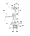
- FIG. 3 is a perspective view showing a configuration of a lens barrel including an actuator for optical equipment according to an embodiment of the present disclosure.
- FIG. 2 is an exploded view of each component forming the lens barrel of FIG. 1.
- FIG. 3 is an exploded view of each part that constitutes the third group and fourth group units included in the lens barrel of FIG. 2.
- FIG. 4 is a front view of the third group and fourth group unit shown in FIG. 3 as viewed from the image sensor side.
- FIG. 6 is a sectional view taken along line JJ of FIG. The figure which looked at the fixed frame contained in the lens barrel of FIG. 2 from the image side.
- FIG. 1 is exploded view of each component forming the lens barrel of FIG. 1.
- FIG. 3 is an exploded view of each part that constitutes the third group and fourth group units included in the lens barrel of FIG. 2.
- FIG. 8 is a sectional view taken along line LL in FIG. 7.
- FIG. 3 is an exploded perspective view showing a configuration around a connecting portion between a piezoelectric element and a spindle guide. Sectional drawing which shows typically the structure of a piezoelectric element periphery, and the structure of the press-fitting part by the side of the 2nd end of a spindle guide.
- FIG. 6 is an enlarged view showing a portion where the spindle guide is press-fitted into a guide holding frame. The figure which shows the transmission model of FIG. The graph which shows the frequency response characteristic of the simplified vibration provision part. The graph which shows the frequency response characteristic of an actual vibration provision part. 6 is a graph showing the relationship between time and amplitude when no vibration is applied. 6 is a graph showing the relationship between time and amplitude when vibration is applied.
- a lens barrel 10 including an actuator for an optical device according to an embodiment of the present disclosure will be described below with reference to FIGS. 1 to 11.
- the lens barrel 10 according to the present embodiment includes an optical system including a plurality of lenses, a first group unit 11, a second group unit 12, and a cam frame 13.
- the third group/fourth group unit 14, the fifth group unit 16, the exterior unit 17, and the base ring 18 are provided.
- the lens barrel 10 is attached to the mount portion of the camera body (not shown) at the base ring 18.
- the optical axis AX direction shown in FIG. 1 is the optical axis direction of the optical system of the lens barrel 10.
- the subject side in the optical axis direction means the side opposite to the image plane side on which the image pickup device (not shown) of the camera body is arranged.
- the optical axis direction of the optical system of the lens barrel 10 will be referred to as the optical axis AX direction.
- (1-1) Configuration of Optical System As shown in FIG. 2, the optical system of the lens barrel 10 includes a first group unit 11, a second group unit 12, a cam frame 13, a third group and a fourth group unit 14. It is composed of a fifth group unit 16, an exterior unit 17, a base ring 18, and the like.
- the first group unit 11 is a tubular member, and a plurality of lenses are arranged on the object side inside thereof.
- the first-group unit 11 moves forward and backward along the optical axis AX while holding a plurality of lenses on the subject side. As a result, the distance between the plurality of lenses changes, and wide-angle shooting and telephoto shooting can be performed.
- the second group unit 12 is a cylindrical member arranged on the inner peripheral surface side of the first group unit 11.
- the second group unit 12 holds a plurality of lenses.
- the plurality of lenses included in the second group unit 12 are arranged closer to the image plane side in the optical axis AX direction than the plurality of lenses included in the first group unit 11.
- the cam frame 13 is a cylindrical member and has a cam groove formed therein.
- the cam frame 13 is arranged on the outer peripheral surface side of the second group unit 12 and the third and fourth group units 14. Then, the cam pins provided on the outer peripheral surface of the third group/fourth group unit 14 are fitted into the cam grooves of the cam frame 13.
- the third-group and fourth-group unit 14 is a focus unit including the focus lens L11, and holds a plurality of lenses like the first-group unit 11 and the second-group unit 12.
- the third group/fourth group unit 14 is a substantially cylindrical member, and holds a plurality of lenses. As shown in FIG. 2, the plurality of lenses included in the third and fourth group units 14 are arranged closer to the image plane side in the optical axis AX direction than the plurality of lenses included in the second group unit 12. Further, the third group/fourth group unit 14 holds a focus lens L11 as shown in FIG.
- the focus lens L11 is arranged on the image plane side in the optical axis AX direction among the plurality of lenses included in the third and fourth group units 14. Further, as shown in FIG.
- the third group/fourth group unit 14 includes a main yoke 31 and an opposing yoke 34 arranged on an outer peripheral portion of a substantially cylindrical fixed frame 30, and a drive coil arranged on the movable frame 33. 33c is included.
- the third group/fourth group unit 14 is driven by the driving unit including the driving coil 33c and the like, so that the movable frame 33 including the focus lens L11 is moved in the optical axis AX direction while holding the plurality of lenses. Move back and forth.
- the cam pins provided so as to project from the outer peripheral surface of the third-group/fourth-group unit 14 (fixed frame 30) receive the rotational driving force applied from the rotational driving source and form a cam groove formed in the cam frame 13. Move along. Thereby, by moving the plurality of lenses included in the first group unit 11 to the third and fourth group units 14 back and forth in the optical axis AX direction, and adjusting the distance between the plurality of lenses, wide-angle shooting and telephoto shooting can be performed. It is possible to take pictures.
- the fifth group unit 16 is a substantially cylindrical member arranged on the inner peripheral surface side of the first group unit 11.
- the fifth group unit 16 holds a plurality of lenses.
- the cam frame 13 is attached to the fifth group unit 16 in a relatively rotatable state.
- the exterior unit 17 is a cylindrical member that forms an exterior portion of the lens barrel 10. An annular focus ring, zoom ring, etc. are rotatably attached to the outer peripheral surface of the exterior unit 17.
- the base ring 18 is attached to the end of the exterior unit 17 on the image plane side, and constitutes the exterior portion of the lens barrel 10 together with the exterior unit 17.
- the base ring 18 is attached to the camera body (not shown).
- (1-2) Configuration of Third-Group/Four-Group Group Unit 14 The lens barrel 10 of the present embodiment is a lens unit that moves the focus lens L11 held by the movable frame 33 back and forth in the optical axis AX direction.
- the third group/fourth group unit 14 constituting the lens barrel 10 includes a fixed frame 30, a main yoke 31, a magnet (driving section) 32 (see FIG. 6, etc.), a movable group.
- a frame 33, a main shaft guide (guide shaft) 40, a sub shaft guide 41, an opposing yoke 34, a guide holding frame (second frame body) 35, and a vibration imparting mechanism 36 are provided.
- the applying mechanism 36 constitutes an actuator for optical equipment that moves the movable frame 33 back and forth along the optical axis AX direction.
- 3 to 8 show the configuration of the third-group/four-group unit 14. 6 is a sectional view taken along line JJ of FIG. 5, and FIG. 8 is a sectional view taken along line LL of FIG.
- the fixed frame 30 is a substantially cylindrical member that forms the outer shell of the third group/fourth group unit 14, and includes a main yoke 31, a magnet 32, a movable frame 33, a main shaft guide (guide shaft) 40, a sub shaft guide 41, and the like. Are placed. Then, a part of the fixed frame 30 is used as a first frame body that constitutes an actuator for an optical device described later.
- the main yoke 31 is a substantially U-shaped member when viewed from the side, and as shown in FIG. 5, two main yokes 31 are provided on the outer peripheral surface side of the fixed frame 30. ..
- the magnet 32 is provided between the substantially U-shaped portions of the main yoke 31, and constitutes an actuator that drives the movable frame 33 together with a drive coil 33c described later. Then, the magnet 32 generates a magnetic field M in the Z direction (inward in the radial direction) shown by the arrow in FIG. More specifically, the magnet 32 arranged on the upper side shown in FIG. 6 generates the magnetic field M downward in the figure, and the magnet 32 arranged on the lower side generates the magnetic field M upward in the figure.
- the movable frame 33 is movable back and forth in the optical axis AX direction relative to the fixed frame 30, and includes a main shaft bearing portion 33a, a sub shaft bearing portion 33b, and a drive coil. It has 33c and the main-body part 33d.
- the spindle bearing portion 33a is a through hole formed in the body portion 33d along the optical axis AX direction, and the spindle guide 40 is inserted therein.
- the sub shaft bearing portion 33b is a through hole formed in the main body portion 33d along the optical axis AX direction, and the sub shaft guide 41 is inserted therein.
- the main shaft guide 40 is slidably engaged with the main shaft bearing portion 33a and serves as a guide member for moving the movable frame 33 relative to the fixed frame 30, as shown in FIGS. It is arranged along the axis AX direction.
- the first end 40a of the main shaft guide 40 in the direction of the optical axis AX is connected to the vibration applying mechanism 36 (piezoelectric element 36a) described later (see FIGS. 8 and 9).
- the second end 40b opposite to the first end 40a is supported in a state of being fixed to the press-fitting hole 35a (see FIGS. 10 and 11) formed in the guide holding frame 35. Further, as shown in FIG. 4, when the movable frame 33 is moved, the spindle guide 40 is given a predetermined vibration in a vibration giving direction in the drawing from a vibration giving mechanism 36 described later.
- the first end 40a of the spindle guide 40 is inserted into an insertion hole 30a formed in the fixed frame 30, as shown in FIG.
- An annular gap d is formed between the inner peripheral surface of the insertion hole 30a and the outer peripheral surface of the spindle guide 40.
- the annular gap d is formed so as to surround the outer peripheral surface of the spindle guide 40.
- the sub shaft guide 41 is inserted into the sub shaft bearing portion 33b, and is arranged substantially parallel to the main shaft guide 40, as shown in FIGS. 3 and 4.
- the auxiliary shaft guide 41 has one end in the optical axis AX direction held by the fixed frame 30 and the opposite end held by a guide holding frame 35 described later.
- the auxiliary shaft guide 41 guides the movable frame 33 so that the movable frame 33 can maintain its posture together with the main shaft guide 40 when the movable frame 33 moves back and forth in the optical axis AX direction along the main shaft guide 40. Functions as a member.
- the drive coil 33c is fixed to the main body 33d side of the movable frame 33, and is arranged near the main yoke 31 and the magnet 32 fixed to the fixed frame 30 side. Then, when the movable frame 33 is moved, a current flows through the drive coil 33c in the X-axis direction perpendicular to the drawing, as shown in FIG. As a result, as shown in FIG. 6, a Lorentz force F1 in the Y-axis direction (left direction) in the figure is applied to the movable frame 33 by the magnetic field generated by the magnet 32 and directed inward in the radial direction and the current flowing through the drive coil 33c. Can be generated. Therefore, when the current flows through the drive coil 33c, the movable frame 33 moves back and forth in the optical axis AX direction.
- the thrust applied to the movable frame 33 depends on the Lorentz force F1 generated by the magnet 32 and the drive coil 33c. That is, in the present embodiment, the thrust of the movable frame 33 does not depend on the vibration applied from the vibration applying mechanism 36 described later.
- the main body portion 33d holds the focus lens L11 in the central portion.
- the main shaft guide 40 and the sub shaft guide 41 are inserted into the main shaft bearing portion 33a and the sub shaft bearing portion 33b provided on the outer peripheral side of the portion of the main body portion 33d that holds the focus lens L11.
- the facing yoke 34 is attached so as to cover the opening portion of the substantially U-shaped main yoke 31.
- the guide holding frame 35 is arranged on the image plane side of the movable frame 33 opposite to the subject side in the optical axis AX direction.
- the guide holding frame 35 holds the ends of the main shaft guide 40 (on the side of the second end 40b) and the auxiliary shaft guide 41 at the position on the image plane side of the movable frame 33.
- the guide holding frame 35 has a press-fitting hole 35a into which the second end 40b of the spindle guide 40 is press-fitted and fixed, and a groove portion 35b formed concentrically with the press-fitting hole 35a on the outer peripheral side of the press-fitting hole 35a.
- the position detector 202 includes a sensor magnet 203 fixed to the movable frame 33 and an MR element (not shown) fixed to the fixed frame 30 so as to face the sensor magnet 203.
- the position detection unit 202 may be configured by an encoder, and may be any unit that can detect the position of the movable frame 33 with respect to the fixed frame 30.
- the position detection unit 202 is electrically connected to the control unit 201 and outputs the movement amount of the sensor magnet 203 in the optical axis direction to the control unit 201.
- the coil terminal unit 205 of the drive coil 33c is electrically connected to the control unit 201.
- the control unit 201 can move the movable frame 33 to a desired position by supplying a drive current to the drive coil 33c based on the current position of the movable frame 33 obtained from the position detection unit 202.
- control unit 201 is also electrically connected to the vibration applying mechanism 36, and can control the operation of the vibration applying unit 36.
- the control unit 201 has a configuration in which the vibration amount and vibration frequency of the vibration applying mechanism 36 can be freely changed according to the current position and speed of the movable frame 33.
- the vibration speed of the main shaft guide shaft is preferably higher than the moving speed of the movable frame 33.
- the control unit 201 causes the vibration imparting unit 36 to move the spindle guide 40 at least twice the moving speed of the movable frame 33 within a range not exceeding the mechanical strength limit. Control to vibrate at the speed of.
- the vibration imparting mechanism 36 has a piezoelectric element 36a, a weight 36b, a spring 36c, a holder (first frame) 36d, and a buffer sheet (buffer material) 36e.
- the vibration applying mechanism 36 is controlled so as to apply vibration within the range of 20 kHz to 60 kHz, for example.
- the piezoelectric element 36a is an element having a piezoelectric property that generates a force when a voltage is applied, and generates an ultrasonic vibration by repeating expansion and contraction when an AC voltage is applied.
- the piezoelectric element 36a applies ultrasonic vibration to the spindle guide 40 in order to reduce frictional resistance generated between the movable frame 33 (main body portion 33d) and the spindle guide 40. Used as.
- the piezoelectric element 36a has a vibration imparting direction (substantially parallel to the axial direction) shown in FIG. 4 so that the static friction generated between the movable frame 33 (main body portion 33d) and the spindle guide 40 is changed to dynamic friction.
- a predetermined ultrasonic vibration is applied to the spindle guide 40 along the horizontal direction).
- the acceleration of the spindle guide 40 vibrating due to ultrasonic vibration is ⁇ and the mass of the movable frame 33 is mk
- the force required for the movable frame 33 to vibrate at the same acceleration ⁇ as the spindle guide 40 is ⁇ .
- the force that can be transmitted from the spindle guide 40 to the movable frame 33 is the frictional force T that acts between the spindle guide 40 and the movable frame 33.
- the spindle guide 40 and the movable frame 33 move substantially integrally. That is, the movable frame 33 vibrates with the acceleration ⁇ in accordance with the vibration of the acceleration ⁇ of the spindle guide 40 by the piezoelectric element 36a.
- the force (friction force T) that can be transmitted to the movable frame 33 is equal to or larger than the force ( ⁇ mk) required for the movable frame 33 to vibrate at the acceleration ⁇ . Therefore, the vibration of the spindle guide 40 is transmitted to the movable frame 33 with the same acceleration ⁇ , and the spindle guide 40 and the movable frame 33 move substantially integrally and do not relatively slide.
- the main shaft guide 40 and the movable frame 33 do not move integrally and a relative slip occurs. That is, even if the spindle guide 40 vibrates at the acceleration ⁇ due to the piezoelectric element 36a, the movable frame 33 cannot vibrate at the acceleration ⁇ and does not vibrate or vibrates at an acceleration smaller than the acceleration ⁇ . When vibrating at an acceleration smaller than the acceleration ⁇ , the amplitude of the movable frame 33 becomes smaller than the amplitude of the spindle guide 40.
- the force (friction force T) that can be transmitted to the movable frame 33 is smaller than the force ( ⁇ mk) required for the movable frame 33 to vibrate at the acceleration ⁇ . Therefore, the vibration of the spindle guide 40 cannot be transmitted to the movable frame 33 at the same acceleration ⁇ , and relative slippage occurs between the spindle guide 40 and the movable frame 33.
- the movable frame 33 vibrates at an acceleration smaller than the acceleration ⁇ . That is, the movable frame 33 may vibrate with an amplitude smaller than that of the spindle guide 40. This vibration amount is smaller than the amplitude of the spindle guide 40 and smaller than the amplitude of the piezoelectric element 36a.
- the amplitude of the piezoelectric element 36a is sufficiently smaller than the accuracy required for position control of the driven body (movable frame 33), and is, for example, 1/10 or less. Therefore, even if the driven body (movable frame 33) is vibrated by the piezoelectric element 36a, there is no problem in position control.
- the ultrasonic vibration applied from the piezoelectric element 36a to the spindle guide 40 can effectively reduce the frictional resistance at the portion where the main body portion 33d of the movable frame 33 and the spindle guide 40 come into contact with each other.
- the Lorentz force F1 (see FIG. 6) generated by the actuator (magnet 32 and drive coil 33c) can move the movable frame 33 to a desired position at high speed and with high accuracy.
- FIG. 12 shows a vibration applying unit 101 that is a simplified version of the vibration applying unit 36 of the present disclosure.
- 102 indicates a weight 36b
- 103 indicates a spring 36c
- 104 indicates a spindle guide 40
- 105 indicates a 35b groove portion
- 106 indicates a piezoelectric element 36a.
- x and X represent the positions of the weight 36b and the spindle guide 40 in the axial direction 109
- F and ( ⁇ F) are the exciting force generated by the piezoelectric element 36a.
- the cushioning sheet 36e is omitted.
- the following expression (100) shows the transfer function from the exciting force ( ⁇ F) to the weight position x of the simplified vibration imparting section 101, and the following expression (101) is the exciting force F to the main axis.
- the transfer function up to the guide position X is shown.
- M1 in the formula (100) represents the mass [kg] of the weight 36b, and m2 in the formula (101) represents the mass (kg) of the spindle guide 40.
- FIG. 13 is a graph showing the frequency response characteristics of equations (100) and (101).
- the dotted line shows the calculation result of the equation (100)
- the solid line shows the calculation result of the equation (101).
- the characteristics of equations (100) and (101) have anti-resonance points at W1 and W2 (which are lower than 10000 Hz and are not shown), and have resonance points at W3 and W4.
- the property is expressed in a quadratic form with. In this configuration, it is set so as to satisfy the following relational expression.
- FIG. 14 shows the characteristics of the actual vibration imparting section, the solid line shows the frequency response characteristics of the spindle guide shaft 40, and the dotted line shows the characteristics of the weight 36b.
- the solid line has peaks corresponding to the theoretical calculation values W3 and W4 shown in the equations (100) and (101) at 32 kHz and 65 kHz, and shows a flat and stable response in the meantime. Further, in the audible range, and in the range of 10 kHz or less where the movable frame 33 is controlled, the vibration response is suppressed to be low.
- the dotted line has a peak similar to the solid line, but has an antiresonance point corresponding to the theoretical calculation value W1 between the peaks, and the vibration response is suppressed.
- the main shaft guide 40 is efficiently vibrated in the target frequency band of 32 kHz to 65 kHz without affecting the movable frame 33 such as noise or control disturbance. It is possible. Further, the vibration of the weight 36b can be suppressed in the desired vibration imparting band, and the influence of the vibration generated on the side of the weight 36b on the external parts can be reduced.
- response waveforms of the movable frame 33 are shown in FIGS. 15A and 15B.
- the dotted line in FIGS. 15A and 15B is the target value, which is a triangular wave of ⁇ 2.3 ⁇ m.
- the solid line in FIG. 15A is the measured waveform of the response value of the movable frame 33 with respect to the target when vibration is not applied.
- the solid line in FIG. 15B is the measured value of the response value of the movable frame 33 with respect to the target value when vibration is applied.
- the movable frame 33 which did not follow the control target of about ⁇ 2 ⁇ m at all, follows the minute target value with extremely high accuracy. Is possible.
- the piezoelectric element 36a is, for example, lead zirconate titanate (Pb (ZrTi) O 3) , barium titanate (BaTiO 3), piezoelectric ceramics such as lead titanate (PbTiO 3) is used.
- the ultrasonic vibration is an elastic vibration wave (sound wave) having a high frequency (for example, a sound that the ear does not feel as a stationary sound having a frequency of 20 kHz or more) that cannot be heard by the human ear, and is in a broad sense. In a sense, it means a sound that is used for a purpose other than what a person hears, regardless of whether or not a person can hear it.
- the weight 36b is a bottomed, substantially cylindrical member, and is connected to the end of the piezoelectric element 36a on the subject side, as shown in FIG.
- the weight 36b has a flange portion 36ba formed at the end portion on the image surface side opposite to the subject side on the substantially cylindrical outer peripheral surface.
- the flange portion 36ba is formed so as to project outward in the radial direction, and is pressed along the axial direction of the spindle guide 40 by a spring 36c described later.
- an end of the piezoelectric element 36a on the side opposite to the side where the main shaft guide 40 is connected to the first end 40a is fixed to the bottom surface of the weight 36b with an adhesive.
- the spring 36c is an elastic member formed as a solenoid spring, and is attached to the outer peripheral surface side of the weight 36b. Then, as shown in FIG. 10, one end of the spring 36c is locked to the flange portion 36ba of the weight 36b, and the other end thereof is held inside the holder 36d and is compressed in the holder. It is arranged in 36d.
- the spring 36c presses the piezoelectric element 36a along the axial direction of the spindle guide 40 (optical axis AX direction) toward the end surface of the first end 40a of the spindle guide 40 via the weight 36b. That is, the spring 36c is provided to transmit the behavior of the piezoelectric element 36a to the spindle guide 40 by urging the piezoelectric element 36a along the direction in which the spindle guide 40 vibrates.
- the spring 36c supports the spindle guide 40 so as to be movable in the direction intersecting the axial direction when an external force is applied in the direction intersecting the axial direction of the spindle guide 40. Accordingly, it is possible to prevent the connection portion between the end surface of the main shaft guide 40 on the first end 40a side and the end surface of the piezoelectric element 36a facing the end surface from being destroyed. Further, vibration-proof grease is applied to the surface of the spring 36c. As a result, the vibration isolation performance of the vibration applying mechanism 36 can be improved.
- the first end 40a side of the main spindle guide 40 is fixed to the inner surface side of the holder 36d described later via the weight 36b and the spring 36c.
- the holder 36d is a bottomed, substantially cylindrical member, and encloses the piezoelectric element 36a, the weight 36b, and the spring 36c in a cylindrical inner space.
- the holder 36d supports the subject side end of the included spring 36c on the bottom surface.
- the holder 36d is fixed to the fixed frame 30 so as to cover the portion of the insertion hole 30a formed in the fixed frame 30.
- the cushioning sheet 36e is a sheet-shaped member formed of, for example, a polyimide resin, and as shown in FIGS. 9 and 10, the end face on the first end 40a side (subject side) of the spindle guide 40 and the piezoelectric member. It is held by the biasing force of the spring 36c between the element 36a and the end surface on the image plane side. Then, the end face of the main shaft guide 40 on the side of the first end 40a and the end face of the piezoelectric element 36a opposed thereto are connected via the cushioning sheet 36e.
- the movable frame 33 including the focus lens L11, the spindle guide 40, and the piezoelectric element 36a are used as an actuator for an optical device that moves the movable frame 33 including the focus lens L11 back and forth in the optical axis AX direction.
- the spindle guide 40 supports the movable frame 33 so as to be movable along the optical axis AX direction of the focus lens L11.
- the piezoelectric element 36a imparts vibration to the first end 40a side of the spindle guide 40.
- the weight 36b is fixed to the piezoelectric element 36a.
- the fixed frame 30 supports the piezoelectric element 36a and the weight 36b arranged on the first end 40a side of the spindle guide 40.
- the guide holding frame 35 supports the main shaft guide 40 on the second end 40b side opposite to the first end 40a side in a fixed state.
- the spring 36c is provided on the first end 40a side of the spindle guide 40, and presses the piezoelectric element 36a in the axial direction against the first end 40a of the spindle guide 40 via the weight 36b.
- the first end 40a side of the main spindle guide 40 is held by the holder via the spring 36c. It is fixed to 36d. Therefore, for example, when an external force is applied from a direction intersecting the axial direction of the spindle guide 40, the first end 40a side of the spindle guide 40 moves in the axial intersecting direction due to the elasticity of the spring 36c.
- the second end 40b side of the spindle guide 40 is supported by the guide holding frame 35 in a fixed state.
- the second end 40b side of the spindle guide 40 can be fixedly supported and the spindle guide 40 can be stably supported, so that the light of a plurality of lenses including the focus lens L11 can be supported.
- the adjustment of the axis AX can be easily performed.
- the first end 40a side of the spindle guide 40 is inserted into the insertion hole 30a formed in the fixed frame 30 via the annular gap d.
- the first end 40a side of the spindle guide 40 can move in the direction intersecting the axial direction within the gap d. ..
- the first end 40a of the spindle guide 40 is supported by the spring 36c described above. Therefore, in the configuration in which the second end 40b side of the main shaft guide 40 is press-fitted and fixed to the guide holding frame 35, even when an external force is applied from a direction intersecting the axial direction, the spindle guide 40 intersects the axial direction within the range of the gap d.
- a buffer sheet 36e is arranged in the connecting portion between the first end 40a of the spindle guide 40 and the piezoelectric element 36a, between the end surface of the first end 40a of the spindle guide 40 and the end surface of the opposing piezoelectric element 36a. Accordingly, in the configuration in which the second end 40b side of the spindle guide 40 is press-fitted and fixed to the guide holding frame 35, even when an external force is applied from a direction intersecting the axial direction of the spindle guide 40, the first end of the spindle guide 40 is provided. Since the buffer sheet 36e absorbs the shearing stress related to the connecting portion between the end surface on the 40a side and the end surface of the piezoelectric element 36a, the destruction of the connecting portion can be prevented more effectively.
- the guide holding frame 35 has an annular groove portion 35b formed around the press-fitting hole 35a for press-fitting and fixing the second end 40b of the spindle guide 40.
- the annular groove portion 35b is arranged concentrically with the press-fitting hole 35a, and the portion around the press-fitting hole 35a of the guide holding frame 35 that fixes the second end 40b side of the spindle guide 40 is deformed and easily moved. It is formed to Therefore, when an external force is applied to the spindle guide 40 in a direction intersecting the axial direction, the vicinity of the press-fitting hole 35a that supports the second end 40b is deformed, and the spindle guide 35a serves as a fulcrum. It is possible to form a state in which 40 can easily move in the direction of the optical axis AX. Then, as described above, the first end 40a side of the spindle guide 40 is supported via the spring 36c.
- the external force can be released by moving the first end 40a side of the spindle guide 40.
- the peripheral portion of the press-fitting hole 35a in which the second end 40b side of the spindle guide 40 is press-fitted and supported has a thin shape due to the annular groove 35b, the vibration imparted to the spindle guide 40 can be absorbed.
- the cushioning material such as the cushioning sheet 36e is provided between the end face of the main shaft guide 40 on the side of the first end 40a and the end face of the piezoelectric element 36a opposed thereto, It is possible to more effectively prevent damage to the connection portion between the end surface of the main shaft guide 40 on the first end 40a side and the end surface of the piezoelectric element 36a facing the end surface.
- the second end 40b side of the spindle guide 40 is press-fitted and fixed in the press-fitting hole 35a of the guide holding frame 35 has been described.
- the present disclosure is not limited to this.
- the fixing of the main shaft guide on the second end side is not limited to press-fitting fixation, but may be fixation using an adhesive or the like.
- C In the above-described embodiment, the example in which the actuator for optical device of the present disclosure is applied to the third group/fourth group unit 14 included in the lens barrel 10 having a plurality of lens groups has been described. However, the present disclosure is not limited to this.
- the target to which the actuator for optical device according to the present disclosure is applied is not limited to, for example, the fourth group unit of the lens barrel, and may be an actuator that drives an image sensor or another movable frame.
- D In the above embodiment, an example in which vibration is applied from the vibration applying mechanism 36 to the spindle guide 40 along a direction substantially parallel to the axial direction of the spindle guide 40 has been described. However, the present disclosure is not limited to this.
- the vibration applied from the vibration applying unit to the spindle guide may be applied along the direction intersecting the axial direction when reducing the dynamic friction resistance, for example.
- E In the above embodiment, an example in which ultrasonic vibration is applied from the vibration applying mechanism 36 to the spindle guide 40 has been described. However, the present disclosure is not limited to this.
- the vibration applied from the vibration applying unit is not limited to ultrasonic vibration, and if vibration that reduces frictional resistance generated between the movable frame and the spindle guide, for example, vibration in the audible range is applied. Good.
- the ultrasonic vibration applied from the vibration applying unit is not limited to the range of 20 kHz to 60 kHz described in the above embodiment, and ultrasonic vibration outside the range may be applied.
- the optical device actuator of the present disclosure has an effect that the optical axis of the lens can be easily adjusted while preventing damage caused by an external force applied from a direction intersecting the axial direction of the guide shaft. Therefore, it can be widely applied as an actuator mounted on various optical devices.
Landscapes
- Physics & Mathematics (AREA)
- General Physics & Mathematics (AREA)
- Optics & Photonics (AREA)
- Lens Barrels (AREA)
- General Electrical Machinery Utilizing Piezoelectricity, Electrostriction Or Magnetostriction (AREA)
Priority Applications (4)
| Application Number | Priority Date | Filing Date | Title |
|---|---|---|---|
| JP2020566172A JP7162188B2 (ja) | 2019-01-18 | 2019-12-23 | 光学機器用アクチュエータおよびこれを備えたレンズ鏡筒 |
| CN201980087211.4A CN113272701B (zh) | 2019-01-18 | 2019-12-23 | 光学设备用致动器以及具备光学设备用致动器的镜头镜筒 |
| EP19910219.5A EP3913415B1 (en) | 2019-01-18 | 2019-12-23 | Optical device actuator and lens barrel provided with same |
| US17/421,597 US12117665B2 (en) | 2019-01-18 | 2019-12-23 | Optical device actuator and lens barrel provided with same |
Applications Claiming Priority (2)
| Application Number | Priority Date | Filing Date | Title |
|---|---|---|---|
| JP2019006701 | 2019-01-18 | ||
| JP2019-006701 | 2019-01-18 |
Publications (1)
| Publication Number | Publication Date |
|---|---|
| WO2020149108A1 true WO2020149108A1 (ja) | 2020-07-23 |
Family
ID=71614361
Family Applications (1)
| Application Number | Title | Priority Date | Filing Date |
|---|---|---|---|
| PCT/JP2019/050347 Ceased WO2020149108A1 (ja) | 2019-01-18 | 2019-12-23 | 光学機器用アクチュエータおよびこれを備えたレンズ鏡筒 |
Country Status (5)
| Country | Link |
|---|---|
| US (1) | US12117665B2 (https=) |
| EP (1) | EP3913415B1 (https=) |
| JP (1) | JP7162188B2 (https=) |
| CN (1) | CN113272701B (https=) |
| WO (1) | WO2020149108A1 (https=) |
Cited By (2)
| Publication number | Priority date | Publication date | Assignee | Title |
|---|---|---|---|---|
| CN115918100A (zh) * | 2021-04-14 | 2023-04-04 | 北京小米移动软件有限公司 | 摄像头致动器 |
| WO2023203793A1 (ja) * | 2022-04-18 | 2023-10-26 | パナソニックIpマネジメント株式会社 | 光学機器用アクチュエータおよびこれを備えたレンズ鏡筒 |
Families Citing this family (3)
| Publication number | Priority date | Publication date | Assignee | Title |
|---|---|---|---|---|
| US11480756B2 (en) * | 2020-12-14 | 2022-10-25 | Karl Storz Imaging, Inc. | Two-speed focusing mechanism |
| CN116299938A (zh) * | 2022-04-07 | 2023-06-23 | 新思考电机有限公司 | 透镜驱动装置、照相装置以及电子设备 |
| JP2024050306A (ja) * | 2022-09-29 | 2024-04-10 | 富士フイルム株式会社 | レンズ機構及びレンズ装置 |
Citations (6)
| Publication number | Priority date | Publication date | Assignee | Title |
|---|---|---|---|---|
| JP2004297920A (ja) * | 2003-03-27 | 2004-10-21 | Minolta Co Ltd | 駆動装置 |
| JP2007049874A (ja) * | 2005-08-12 | 2007-02-22 | Fujinon Corp | アクチュエータ |
| JP2010074912A (ja) * | 2008-09-17 | 2010-04-02 | Konica Minolta Opto Inc | 超音波モータ |
| JP2012189711A (ja) * | 2011-03-09 | 2012-10-04 | Olympus Imaging Corp | アダプタレンズ装置およびレンズ鏡筒 |
| WO2014091656A1 (ja) | 2012-12-12 | 2014-06-19 | コニカミノルタ株式会社 | 駆動装置および撮像装置 |
| WO2014174750A1 (ja) * | 2013-04-24 | 2014-10-30 | コニカミノルタ株式会社 | 駆動装置およびこれを用いた撮像装置 |
Family Cites Families (11)
| Publication number | Priority date | Publication date | Assignee | Title |
|---|---|---|---|---|
| JP4906326B2 (ja) | 2005-11-30 | 2012-03-28 | 富士フイルム株式会社 | 駆動装置及び駆動装置の製造方法 |
| JP4795083B2 (ja) | 2006-04-10 | 2011-10-19 | パナソニック株式会社 | 圧電駆動装置、撮像装置、および携帯端末装置 |
| JP2014220909A (ja) | 2013-05-08 | 2014-11-20 | コニカミノルタ株式会社 | 駆動装置およびこれを用いた撮像装置 |
| JP6155460B2 (ja) | 2013-06-06 | 2017-07-05 | 新シコー科技株式会社 | 駆動部材、リニア駆動装置、カメラ装置及び電子機器 |
| JP5895985B2 (ja) | 2014-08-07 | 2016-03-30 | Tdk株式会社 | 圧電駆動装置 |
| JP6553912B2 (ja) * | 2015-03-30 | 2019-07-31 | 蛇の目ミシン工業株式会社 | ミシンの外釜 |
| JP6565964B2 (ja) | 2017-04-05 | 2019-08-28 | Tdk株式会社 | 圧電アクチュエータ |
| CN207680945U (zh) * | 2017-11-16 | 2018-08-03 | 山东品创机械设备有限公司 | 一种压电陶瓷振动源及使用该振动源的机床和工业机器人 |
| JP2019120886A (ja) * | 2018-01-11 | 2019-07-22 | キヤノン株式会社 | 像振れ補正装置およびその制御方法 |
| US10611597B1 (en) * | 2018-01-19 | 2020-04-07 | Amazon Technologies, Inc. | Device for roller assembly, and related systems and methods |
| WO2019244852A1 (ja) * | 2018-06-21 | 2019-12-26 | Tdk株式会社 | レンズ駆動装置 |
-
2019
- 2019-12-23 JP JP2020566172A patent/JP7162188B2/ja active Active
- 2019-12-23 US US17/421,597 patent/US12117665B2/en active Active
- 2019-12-23 WO PCT/JP2019/050347 patent/WO2020149108A1/ja not_active Ceased
- 2019-12-23 CN CN201980087211.4A patent/CN113272701B/zh active Active
- 2019-12-23 EP EP19910219.5A patent/EP3913415B1/en active Active
Patent Citations (6)
| Publication number | Priority date | Publication date | Assignee | Title |
|---|---|---|---|---|
| JP2004297920A (ja) * | 2003-03-27 | 2004-10-21 | Minolta Co Ltd | 駆動装置 |
| JP2007049874A (ja) * | 2005-08-12 | 2007-02-22 | Fujinon Corp | アクチュエータ |
| JP2010074912A (ja) * | 2008-09-17 | 2010-04-02 | Konica Minolta Opto Inc | 超音波モータ |
| JP2012189711A (ja) * | 2011-03-09 | 2012-10-04 | Olympus Imaging Corp | アダプタレンズ装置およびレンズ鏡筒 |
| WO2014091656A1 (ja) | 2012-12-12 | 2014-06-19 | コニカミノルタ株式会社 | 駆動装置および撮像装置 |
| WO2014174750A1 (ja) * | 2013-04-24 | 2014-10-30 | コニカミノルタ株式会社 | 駆動装置およびこれを用いた撮像装置 |
Non-Patent Citations (1)
| Title |
|---|
| See also references of EP3913415A4 |
Cited By (4)
| Publication number | Priority date | Publication date | Assignee | Title |
|---|---|---|---|---|
| CN115918100A (zh) * | 2021-04-14 | 2023-04-04 | 北京小米移动软件有限公司 | 摄像头致动器 |
| WO2023203793A1 (ja) * | 2022-04-18 | 2023-10-26 | パナソニックIpマネジメント株式会社 | 光学機器用アクチュエータおよびこれを備えたレンズ鏡筒 |
| JPWO2023203793A1 (https=) * | 2022-04-18 | 2023-10-26 | ||
| JP7745179B2 (ja) | 2022-04-18 | 2025-09-29 | パナソニックIpマネジメント株式会社 | 光学機器用アクチュエータおよびこれを備えたレンズ鏡筒 |
Also Published As
| Publication number | Publication date |
|---|---|
| CN113272701A (zh) | 2021-08-17 |
| US20220163752A1 (en) | 2022-05-26 |
| JP7162188B2 (ja) | 2022-10-28 |
| JPWO2020149108A1 (ja) | 2021-11-11 |
| US12117665B2 (en) | 2024-10-15 |
| EP3913415A4 (en) | 2022-03-16 |
| EP3913415B1 (en) | 2024-12-18 |
| EP3913415A1 (en) | 2021-11-24 |
| CN113272701B (zh) | 2023-02-03 |
Similar Documents
| Publication | Publication Date | Title |
|---|---|---|
| JP7162188B2 (ja) | 光学機器用アクチュエータおよびこれを備えたレンズ鏡筒 | |
| JP5132295B2 (ja) | 撮像装置および光学機器 | |
| JP7336740B2 (ja) | 光学機器用アクチュエータおよびこれを備えたレンズ鏡筒 | |
| WO2018139581A1 (ja) | 駆動装置、光学機器及び撮像装置 | |
| JP2006330053A (ja) | レンズ鏡胴 | |
| JP2006330054A (ja) | レンズ鏡胴 | |
| JP7313909B2 (ja) | 振動波モータおよび電子機器。 | |
| JP7352902B2 (ja) | レンズ鏡筒およびこれを備えた撮像装置 | |
| JP2012029495A (ja) | 駆動装置 | |
| US11533002B2 (en) | Vibration type motor, optical apparatus, and driving apparatus using damper to suppress noise | |
| JP2016027780A (ja) | 振動型アクチュエータ、レンズ鏡筒、撮像装置及び自動ステージ | |
| US11336211B2 (en) | Vibration wave motor and driving apparatus using vibration wave motor | |
| JP6812510B2 (ja) | 振動型アクチュエータ及びそれを有する電子機器 | |
| JP7745179B2 (ja) | 光学機器用アクチュエータおよびこれを備えたレンズ鏡筒 | |
| JP2012227988A (ja) | 振動型リニアアクチュエータとそれを有する光学機器 | |
| JP2016158386A (ja) | 振動型駆動装置、レンズ鏡筒及び撮像装置 | |
| JP6753756B2 (ja) | 駆動装置、及びカメラモジュール | |
| JP4677145B2 (ja) | 画像読取装置及び画像形成装置 | |
| US20250314851A1 (en) | Vibration type actuator, lens barrel, image capturing apparatus, and stage apparatus | |
| JP6537482B2 (ja) | 振動波モータおよび電子機器 | |
| JP2020005374A (ja) | 振動型モータおよび駆動装置 | |
| JP2010139726A (ja) | 光学機器 | |
| JP2010032806A (ja) | レンズ駆動ユニット及び電子光学装置 | |
| JP2009229710A (ja) | 駆動装置 | |
| JP2005348575A (ja) | 駆動装置 |
Legal Events
| Date | Code | Title | Description |
|---|---|---|---|
| 121 | Ep: the epo has been informed by wipo that ep was designated in this application |
Ref document number: 19910219 Country of ref document: EP Kind code of ref document: A1 |
|
| ENP | Entry into the national phase |
Ref document number: 2020566172 Country of ref document: JP Kind code of ref document: A |
|
| NENP | Non-entry into the national phase |
Ref country code: DE |
|
| ENP | Entry into the national phase |
Ref document number: 2019910219 Country of ref document: EP Effective date: 20210818 |