WO2020148983A1 - 空気式防舷材およびその製造方法 - Google Patents
空気式防舷材およびその製造方法 Download PDFInfo
- Publication number
- WO2020148983A1 WO2020148983A1 PCT/JP2019/044349 JP2019044349W WO2020148983A1 WO 2020148983 A1 WO2020148983 A1 WO 2020148983A1 JP 2019044349 W JP2019044349 W JP 2019044349W WO 2020148983 A1 WO2020148983 A1 WO 2020148983A1
- Authority
- WO
- WIPO (PCT)
- Prior art keywords
- main body
- reinforcing
- reinforcing layers
- layer
- gaps
- Prior art date
- Legal status (The legal status is an assumption and is not a legal conclusion. Google has not performed a legal analysis and makes no representation as to the accuracy of the status listed.)
- Ceased
Links
Images



Classifications
-
- B—PERFORMING OPERATIONS; TRANSPORTING
- B63—SHIPS OR OTHER WATERBORNE VESSELS; RELATED EQUIPMENT
- B63B—SHIPS OR OTHER WATERBORNE VESSELS; EQUIPMENT FOR SHIPPING
- B63B59/00—Hull protection specially adapted for vessels; Cleaning devices specially adapted for vessels
- B63B59/02—Fenders integral with waterborne vessels or specially adapted therefor, e.g. fenders forming part of the hull or incorporated in the hull; Rubbing-strakes
-
- E—FIXED CONSTRUCTIONS
- E02—HYDRAULIC ENGINEERING; FOUNDATIONS; SOIL SHIFTING
- E02B—HYDRAULIC ENGINEERING
- E02B3/00—Engineering works in connection with control or use of streams, rivers, coasts, or other marine sites; Sealings or joints for engineering works in general
- E02B3/20—Equipment for shipping on coasts, in harbours or on other fixed marine structures, e.g. bollards
- E02B3/26—Fenders
-
- B—PERFORMING OPERATIONS; TRANSPORTING
- B63—SHIPS OR OTHER WATERBORNE VESSELS; RELATED EQUIPMENT
- B63B—SHIPS OR OTHER WATERBORNE VESSELS; EQUIPMENT FOR SHIPPING
- B63B59/00—Hull protection specially adapted for vessels; Cleaning devices specially adapted for vessels
- B63B59/02—Fenders integral with waterborne vessels or specially adapted therefor, e.g. fenders forming part of the hull or incorporated in the hull; Rubbing-strakes
- B63B2059/025—Fenders integral with waterborne vessels or specially adapted therefor, e.g. fenders forming part of the hull or incorporated in the hull; Rubbing-strakes pneumatic, e.g. inflatable
-
- Y—GENERAL TAGGING OF NEW TECHNOLOGICAL DEVELOPMENTS; GENERAL TAGGING OF CROSS-SECTIONAL TECHNOLOGIES SPANNING OVER SEVERAL SECTIONS OF THE IPC; TECHNICAL SUBJECTS COVERED BY FORMER USPC CROSS-REFERENCE ART COLLECTIONS [XRACs] AND DIGESTS
- Y02—TECHNOLOGIES OR APPLICATIONS FOR MITIGATION OR ADAPTATION AGAINST CLIMATE CHANGE
- Y02A—TECHNOLOGIES FOR ADAPTATION TO CLIMATE CHANGE
- Y02A30/00—Adapting or protecting infrastructure or their operation
- Y02A30/30—Adapting or protecting infrastructure or their operation in transportation, e.g. on roads, waterways or railways
Definitions
- the present invention relates to a pneumatic fender and a method for manufacturing the same, and more specifically, when a prescribed internal pressure is applied to the main body, the body portion that expands and the vicinity of the boundary between the body portion and the mirror portion are smoothly expanded.
- the present invention relates to a pneumatic fender that facilitates securing a body having a predetermined shape and a method for manufacturing the same.
- Pneumatic fenders generally have a main body with bowl-shaped mirrors at both ends of a cylindrical body, and the main body has a plurality of reinforcing layers laminated between an inner rubber layer and an outer rubber layer. Is configured.
- each reinforcing layer is formed by arranging a large number of cords in parallel, and the cords are arranged at a predetermined cord angle with respect to the cylinder axis direction.
- the cords of the reinforcing layers that are laminated and adjacent to each other are in an intersecting state (so-called bias structure).
- the size of the main body will be large even if the inside of the main body is filled with air and a specified internal pressure is applied.
- the length (length and outer diameter) does not change much.
- a pneumatic fender has been proposed in which the cord angle of the reinforcing layer of the body is set to 15° or more and 45° or less in the neutral state where the main body is not expanded (see Patent Document 1).
- the cord angle of the reinforcing layer of the body portion tends to increase to a rest angle.
- the body portion is greatly expanded in diameter and inflated, so that it is compact when not in use, but can obtain excellent cushioning performance (reaction force) during use.
- the reinforcing layer of the mirror part is not set to a cord angle of 15° or more and 45° or less in the neutral state where the main body is not expanded. Therefore, even if a prescribed internal pressure is applied to the main body, the diameter near the boundary between the mirror portion and the body portion does not expand smoothly and greatly. As a result, distortion occurs near the boundary between the mirror portion and the body portion, so that it is not possible to secure the main body expanded to a predetermined shape.
- An object of the present invention is to provide a pneumatic fender that smoothly expands the body near the boundary between the body and the mirror together with the body that expands when a prescribed internal pressure is applied to the body, and makes it easy to secure a body of a predetermined shape. It is to provide a material and a manufacturing method thereof.
- the pneumatic fender of the present invention comprises a main body having a cylindrical body portion and bowl-shaped mirror portions connected to both ends of the body portion, the main body having an inner rubber layer and an outer layer.
- a plurality of reinforcing layers are laminated between the rubber and each of the reinforcing layers in the body portion by a large number of cords extending in parallel with each other at a predetermined cord angle with respect to the cylinder axis direction. It has a bias structure in which the cords of the reinforcing layers adjacent to each other that are formed and laminated are crossed, and the cord angle is set to 25° or more and 45° or less in a neutral state where the main body is not expanded.
- each of the reinforcing layers of the body portion in the cylinder axis direction and the corresponding reinforcing layers of the mirror portion are opposed to each other with a gap
- Opposing members are joined to each other via a joining member disposed in each of the gaps
- each joining member is formed by a large number of cords that are aligned in parallel and extend, and While the multiple cords extend in the same direction as the cords of the corresponding reinforcing layer of the body to be joined, the cords of the reinforcing layer of the joining subject in a neutral state in which the body is not expanded
- the code angle is set to ⁇ 10° of the code angle
- each of the gaps has a plurality of different sizes, and each of them is arranged in a circumferential direction of the mirror portion having an arc shape in a side view of the main body.
- One end of the gap is set to a plurality of different positions, and the other end of each gap is set to a plurality of different positions.
- a method for manufacturing a pneumatic fender of the present invention is a method for manufacturing the above pneumatic fender, which is a cylindrical body molding mold and is connected to both ends of the body molding mold.
- the barrel mold and the mirror mold are separated from each other, and the barrel is placed inside the barrel mold. Laminating each of the reinforcing layers constituting, laminating each of the reinforcing layers constituting the mirror portion inside each of the molding mold for the mirror portion, each of the both ends of the molding mold for the body portion
- both end portions in the cylinder axis direction of the respective reinforcing layers constituting the body part and the corresponding respective reinforcing layers of the mirror part are opposed to each other with a gap.
- the joining member is sequentially arranged in each of the gaps to form a reinforcing body composed of the respective reinforcing layers, and the outer layer rubber and the inner layer rubber are respectively provided on the outer surface and the inner surface of the reinforcing body. It is characterized in that the bag body in which the unvulcanized rubber to be formed is laminated is vulcanized under a predetermined condition to obtain the bag body.
- the pneumatic fender of the present invention is arranged not only in the reinforcing layers that form the trunk, but also in the respective gaps between these reinforcing layers and the reinforcing layers that form the mirror section that is arranged facing each other.
- the joining member also has a bias structure in which cords that are stacked and adjacent to each other intersect each other.
- the cord angle of the reinforcing layer of the body is set to 25° or more and 45° or less in the neutral state where the cord is not expanded, and the cord angle and the cord angle of the joining member are set to substantially the same angle.
- each cord angle tries to increase to a stable static angle, so that it is easy to expand along with the body part near the boundary between the body part and the mirror part.
- the size of each gap is different from each other, and one end position of each gap is different from each other in the circumferential direction of the arc-shaped mirror portion in the side view of the main body.
- the other end of is also different in multiple types. Therefore, the joining positions of the respective joining members and the respective reinforcing layers are dispersed in the circumferential direction, so that the difference in rigidity of the main body in the circumferential direction is suppressed.
- a pneumatic fender of the present invention using a cylindrical barrel molding mold, and a bowl-shaped mirror molding mold connected to both ends of this barrel molding mold, After the reinforcing layer forming the body is separated from the laminated body and the reinforcing layer forming the respective mirror portions and molded, the laminated bodies are joined together by the joining member to reinforce each other.
- the pneumatic fender can be efficiently manufactured by molding the reinforcing body composed of layers.
- FIG. 1 is an explanatory view illustrating, in a side view, a pneumatic fender of the present invention in a neutral state where the main body is not expanded, with a part of a member of the main body cut away.
- FIG. 2 is an explanatory view illustrating the pneumatic fender of FIG. 1 in front view.
- FIG. 3 is an explanatory view illustrating the internal structure of the main body of FIG. 1 in a cross-sectional view.
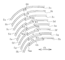
- FIG. 4 is an explanatory diagram illustrating, in a front view, the state of the reinforcing layer in the end area of the mirror portion of FIG. 1.
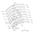
- FIG. 5 is an explanatory view schematically illustrating a connection structure of the reinforcing layer of the body portion and the mirror portion of FIG.
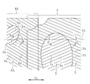
- FIG. 6 is an explanatory view illustrating the connection structure of FIG. 5 in plan view.
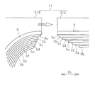
- FIG. 7 is an explanatory view illustrating the molding process of the main body of FIG. 1 in a longitudinal sectional view.
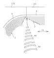
- FIG. 8 is an explanatory view illustrating, in a vertical cross-sectional view, a step of arranging a member in a gap between the reinforcing layer forming the body portion and the reinforcing layer forming the mirror portion of FIG. 7.
- FIG. 9 is an explanatory view illustrating a side view of the pneumatic fender of FIG. 1 in which a predetermined internal pressure is applied to the main body to expand it into a predetermined shape by cutting out a part of the member of the main body.
- FIG. 10 is an explanatory diagram showing a modification of the connection structure of FIG.
- the pneumatic fender 1 (hereinafter referred to as fender 1) of the present invention illustrated in FIGS. 1 to 5 is a main body 1A in which a bowl-shaped mirror portion 4 is connected to both ends of a cylindrical body portion 2.
- the base portion 10 provided on the main body 1A.
- the base portion 10 is provided on one mirror portion 4, but it may be provided on both side mirror portions 4.
- the body portion 2 is configured by laminating a plurality of reinforcing layers 3 (3a to 5h) between an inner rubber layer 7 and an outer rubber layer 8.
- the mirror portion 4 is configured by laminating a plurality of reinforcing layers 5 (5a to 5h) between an inner rubber layer 7 and an outer rubber layer 8.
- the number of laminated layers of each of the reinforcing layers 3 and 5 is 8, but not limited to this, and the number of laminated layers of each is, for example, in the range of 6 or more and 18 or less.
- the number of laminated layers of the reinforcing layers 3 and 5 is basically the same.
- An intermediate rubber layer 9 is interposed between the reinforcing layers 3 (3a to 3h) and between the reinforcing layers 5 (5a to 5h).
- the rubber forming the intermediate rubber layer 9 for example, natural rubber, butyl rubber, styrene butadiene rubber, acrylonitrile butadiene rubber or the like is used.
- the rubber forming the inner layer rubber 7 for example, natural rubber, butyl rubber, styrene butadiene rubber, acrylonitrile butadiene rubber, etc. are used.
- the rubber forming the outer layer rubber 8 for example, natural rubber, styrene butadiene rubber, acrylonitrile butadiene rubber, ethylene propylene rubber or the like is used.
- Each of the reinforcing layers 3 (3a to 3h) forming the body portion 2 is formed by a large number of cords 3x extending in parallel with each other at a predetermined cord angle A with respect to the cylinder axis direction CL. Then, a bias structure is formed in which the cords 3x of the reinforcing layers 3 that are stacked and adjacent to each other intersect. That is, the cords 3x of the reinforcing layers 3a, 3c, 3e, and 3g extend in the same direction and are arranged at the cord angle A.
- the cords 3x of the reinforcing layers 3b, 3d, 3f, 3h extend in the same direction as each other and are arranged at the cord angle A, and these cords 3x intersect the cords 3x of the reinforcing layers 3a, 3c, 3e, 3g. It is facing. In this way, the laminated body of the reinforcing layers 3 has a so-called bias structure.
- Each mirror portion 4 is composed of a predetermined range 4A in the cylinder axis direction CL on the boundary side with the body 2 and an end range 4B other than the predetermined range 4A.
- Each of the reinforcing layers 5 (5a to 5h) forming the mirror portion 4 has a cord layer formed of cords 5x radially extending from the circular center of the mirror portion 4 and a circumference, as illustrated in FIG. The cords are formed by alternately laminating cord layers formed of cords 5x extending in the direction. That is, the laminated body of the reinforcing layer 5 of the mirror portion 4 has a so-called radial structure.
- the boundary between the body portion 2 and the predetermined range 4A and the boundary between the predetermined range 4A and the end range 4B are indicated by thin broken lines and are linearly divided. Are not necessarily linearly divided.
- the predetermined range 4A of the mirror portion 4 is a connecting portion between the body portion 2 and the mirror portion 4, and a connecting member 6A is arranged as illustrated in FIG. That is, the reinforcing layer 3 of the body portion 2 and the reinforcing layer 5 of the mirror portion 4 are joined by the joining member 6A.
- the connection structure between the reinforcing layer 3 and the reinforcing layer 5 will be described later.
- Each of the joining members 6A is formed of a large number of cords 6x extending in parallel with each other at a predetermined cord angle B with respect to the cylinder axis direction CL.
- Steel cords, organic fiber cords or the like are used as the cords 3x, 5x, 6x.
- the outer diameter of the cords 3x, 5x, 6x is, for example, in the range of 0.5 mm or more and 1.5 mm or less.
- the code 3x, the code 5x, and the code 6x basically have the same specifications, but they may have different specifications, or any one of them may have different specifications.
- the code angle A is set to 25° or more and 45° or less in the neutral state where the main body 1A is not expanded.
- the cord angle B of the joining member 6A is set to ⁇ 10° of the cord angle A of the reinforcing layer 3 to be joined, and the cords 6x and 3x extend in the same direction. There is.
- the cord angle B of the joining member 6A joined to the reinforcing layer 3a is set to ⁇ 10° of the cord angle A of the reinforcing layer 3a, the cords 6x, 3x extend in the same direction, and the reinforcing layer 3b
- the cord angle B of the joining member 6A joined to is set to ⁇ 10° of the cord angle A of the reinforcing layer 3b, and the cords 6x and 3x extend in the same direction.
- the neutral state in which the main body 1A is not expanded is a state in which tension is not substantially generated in the cords 3x, 5x, 6X, and air is injected into the main body 1A, but the internal pressure is higher than the atmospheric pressure. Is slightly higher (for example, 10 kPa). Then, the body portion 2 is in a cylindrical shape and the mirror portion 4 is in a bowl shape.
- the layer thickness of the inner rubber layer 7 is, for example, in the range of 2 mm or more and 5 mm or less, and the outer rubber layer 8 is in the range of, for example, 3 mm or more and 12 mm or less.
- the thickness of the intermediate rubber layer 9 is, for example, less than 1 mm in this neutral state, and more preferably 0.2 mm or more and 0.6 mm or less.
- the outer diameter D of the body portion 2 is in the range of 2 m or more and 8 m or less in this neutral state.
- the gaps between the respective axial end portions of the respective reinforcing layers 3 of the body portion 2 and the corresponding respective reinforcing layers 5 of the mirror portion 4 are provided. Opposite with S. That is, opposing members such as the reinforcing layers 3a and 5a, the reinforcing layers 3b and 5b, and the reinforcing layers 3c and 5c are joined to each other through the joining member 6A arranged in each gap S.
- the joining length (overlap length) between each reinforcing layer 3 and the joining member 6A and the joining length (overlap length) between each reinforcing layer 5 and the joining member 6A are set to the minimum necessary to ensure rigidity. Avoid getting high locally.
- the cords 6x of the respective joining members 6A extend in the same direction as the cords 3x of the corresponding reinforcing layer 3 to be joined, and in the neutral state where the main body 1A is not expanded.
- the cord angle B of the cord angle A of the cord 3x of the reinforcement layer 3 to be joined is ⁇ 10°.
- the gaps S between the reinforcing layers 3 and 5 facing each other have a plurality of different sizes.
- each gap S increases as it is located on the inner peripheral side of the main body 1A. That is, the gap S between the reinforcing layers 3a and 5a is the smallest, and the gap S between the reinforcing layers 3h and 5h is the largest.
- the sizes of all the gaps S may be different, but there may be a plurality of gaps S of the same size, but it is preferable that the size of the gaps S of a majority or more is different.
- one end E1 of each gap S is set at a plurality of different positions with respect to the circumferential direction of the arc-shaped mirror portion 4 in a side view of the main body 1A, and the other end E2 of each gap S is set.
- the different positions with respect to the circumferential direction of the arc-shaped mirror portion 4 are set such that the arc shape is a circle having a predetermined radius, and are arranged on the same straight line extending from the center of the circle to the arc. It means that the one end E1 is not located.
- the two one ends E1 are located on one straight line extending from the center of the circle to the arc, the two one ends E1 are the circles of the arc-shaped mirror portion 4. It means that they are set at the same position in the circumferential direction. This also applies to the other end E2.
- the molding mold 11B is used.
- the reinforcing molds 3 (3a to 3h) forming the body 2 are laminated inside the body forming mold 11A with the body forming mold 11A and the respective mirror forming molds 11B separated from each other.
- Reinforcing layers 5 (5a to 5h) forming the mirror portion 4 are laminated inside the respective mirror portion molding molds 11B to form a laminate.
- the unvulcanized rubber forming the outer rubber layer 8 is provided between the reinforcing layer 3a and the inner peripheral surface of the body molding mold 11A, and between the reinforcing layer 5a and the inner peripheral surface of the mirror molding mold 11B. To place.
- the respective body forming molds 11B are connected to both ends of the body forming mold 1A. It is not necessary to connect the respective body part molding molds 11B to the body part molding mold 1A at the same time, and they may be sequentially connected one by one. Then, both ends of the laminated body of the respective reinforcing layers 3 (3a to 3h) forming the body portion 2 in the cylinder axis direction and the laminated body of the corresponding respective reinforcing layers (5a to 5h) of the mirror portion 4 are The gaps S are opposed to each other, and the joining members 6A located on the outer peripheral side of the main body 1A are sequentially arranged in the respective gaps S.
- a reinforcing body including the reinforcing layers 3 and 5 is formed.
- An unvulcanized rubber forming the inner rubber layer 7 is laminated on the inner surface of the reinforcing body.
- the base portion 10 is attached to the mirror portion 4 at a predetermined position when the reinforcing layer 5 is laminated.
- the main body 1A is manufactured by vulcanizing under predetermined conditions. Since the main body 1A is sufficiently large, a worker can enter the inside thereof to work. Further, the worker can enter and leave the inside of the main body 1A through the mouthpiece part 10.
- the method of manufacturing the main body 1A as described above even with one type of molding mold 11, by appropriately setting the respective cord angles A and B of the reinforcing layer 3 and the joining member 6A, it is possible to obtain a plurality of sizes. It becomes possible to manufacture the fender 1. That is, since it is not necessary to prepare a dedicated molding mold 11 for each size of the fender 1, there is a great merit in reducing the cost required for manufacturing equipment.
- the internal pressure of the main body 1A is set to a low pressure of, for example, about 10 kPa so as to be in a non-expanded neutral state as illustrated in FIG. Further, the air inside the main body 1A is discharged to be in a folded state.
- the main body 1A When the fender 1 is attached to the installation location and used, the main body 1A is inflated to maintain a predetermined shape as illustrated in FIG. Specifically, a prescribed internal pressure P is applied by filling the inside of the main body 1A with air through a valve installed in the base 10.
- the specified internal pressure P is, for example, in the range of 50 kPa or more and 100 kPa or less.
- the cord angle A in each of the reinforcing layers 3 of the body portion 2 tends to increase to a stable static angle (54° to 55°). .. Even in the predetermined range 4A, in the process of setting the main body 1A to the specified internal pressure P, the cord angle B of each joining member 6A tends to increase to a stable stationary angle (54° to 55°).
- the joining member 6A also has a bias structure.
- the cord angle A and the cord angle B of the reinforcing layer 3 and the joint member 6A that are joined are set to be substantially the same. Therefore, when the main body 1A is filled with air and the prescribed internal pressure P is loaded, the cord angle B of each joining member 6A tends to increase to a stable static angle, so that the body portion 2 and the body portion 2 and the mirror portion are together.
- the vicinity of the boundary with 4 (predetermined range 4A) also easily expands.
- the shape of the end area 4B is the same as the trunk portion 2 and the predetermined area 4A. It does not significantly deform with respect to the shape of the state.
- each gap S is different in a plurality of types, and one end E1 of each gap S has a plurality of different positions in the circumferential direction of the arc-shaped mirror portion 4 in a side view of the main body 1A. And the other end E2 of each is also in a plurality of different positions. Therefore, the joining positions (overlap positions) of the respective joining members 6A and the respective reinforcing layers 3, 5 are dispersed in the circumferential direction, so that the rigidity difference of the main body 1A in the circumferential direction is suppressed. To be done. Due to this, when the prescribed internal pressure P is applied to the main body 1A, the strain generated near the boundary between the body portion 2 and the mirror portion 4 is corrected, and it becomes easy to obtain the main body 1A expanded to a predetermined shape.
- the outer diameter of the body 2 and the body 1A It becomes easy to secure an ideal predetermined shape with a ratio of 1A to the dimension in the longitudinal direction (cylinder axis direction) of 1:2.
- cord angles A and B in the neutral state are less than 25°, it is not preferable to increase the cord angle A to a rest angle because excessive shear stress is generated in the intermediate rubber layer 9. If the cord angles A and B exceed 45°, the degree of expansion of the body portion 2 and the mirror portion 4 in the predetermined range 4A when expanded from the neutral state to the specified internal pressure P becomes small. It is more preferable that the cord angles A and B be 30° or more and 35° or less.
- the one end Tma on the end range 4B side of each joining member 6A shown in FIG. 5 is set to an appropriate range. That is, it is desirable that the one end Tma is set within the range indicated by the angle b when the main body 1A is in the neutral state as illustrated in FIG.
- the range of the angle b is 0.2 or more and 0.4 or less (0.2D or more and 0D or less of the outer diameter D of the body 1A from the surface of the body 2 on the boundary line between the body 2 and the mirror portion 4). .4D or less)
- the angle b is 0° or more and 46° or less.
- the respective joining members 6A are arranged in the respective gaps S as a single layer sheet material, but the specifications may be different.
- the reinforcing layer 3 forming the body portion 2 and the reinforcing layer 5 forming each mirror portion 4 are 6 layers or more, it is preferable to adopt the specifications illustrated in FIG.
- the above-described joining member is provided in the sixth or more reinforcing layers 3f, 3g, 3h (5f, 5g, 5h) from the outer peripheral side to the inner peripheral side of the main body 1A.
- 6A and another joining member 6B joined to the end of the joining member 6A on the mirror portion side are arranged.
- the members (reinforcing layers 3f and 5f, reinforcing layers 3g and 5g, reinforcing layers 3h and 5h) facing each other with the gap S interposed therebetween are joined via the joining member 6A and another joining member 6B arranged in the gap S. It is joined.
- the joining length (overlap length) of each joining member 6A and joining member 6B, and the joining length (overlap length) of each reinforcing layer 5 and joining member 6B are set to the minimum necessary to ensure rigidity. Avoid getting high locally.
- the other joining member 6B is also formed by a large number of cords that are aligned and extend in parallel to the cylinder axis direction CL at a predetermined cord angle.
- the cord angle of the other joining member 6B is set smaller than the cord angle B of the joining member 6A being joined. Therefore, the joining member 6B may be used by using the same material as that of the joining member 6A and having a cord angle different from that of the joining member 6A.
- the one end Tmb of each of the different joining members 6B is located closer to the end portion range 4B than the range of the angle b shown in FIG.
- the reinforcing layers 3 and 5 arranged on the inner peripheral side are joined together by using the joining members 6A and 6B, whereby the internal pressure of the main body 1A is regulated.
- P When P is loaded, the body portion 2 that expands and the vicinity of the boundary between the body portion 2 and the mirror portion 4 are smoothly expanded, and the main body 1A having a predetermined shape can be more easily secured.
- Air Fender 1A Main Body 2 Body 3 (3a to 3h) Reinforcing Layer 3x Cord 4 Mirror 4A Predetermined Range 4B End Range 5 (5a to 5h) Reinforcing Layer 5x Code 6A, 6B Joining Member 6x Code 7 Inner Layer Rubber 8 Outer layer rubber 9 Intermediate rubber layer 10 Mouth portion 11 (11A, 11B) Molding mold S gap
Landscapes
- Engineering & Computer Science (AREA)
- General Engineering & Computer Science (AREA)
- Ocean & Marine Engineering (AREA)
- Mechanical Engineering (AREA)
- Environmental & Geological Engineering (AREA)
- Civil Engineering (AREA)
- Structural Engineering (AREA)
- Chemical & Material Sciences (AREA)
- Combustion & Propulsion (AREA)
Abstract
本体に規定内圧を負荷した際に、胴部と鏡部との境界付近を円滑に膨張させて所定形状の本体を確保し易くした空気式防舷材とその製造方法を提供する。胴部2を構成するバイアス構造の補強層3のコード角度Aを、本体1Aが中立状態で25°以上45°以下に設定し、胴部2と鏡部4の筒軸方向に対向する補強層3、5どうしのすき間Sに配置された接合部材6Aを介して補強層3、5どうしを接合し、積層された接合部材6Aは、胴部2の補強層3と同様のバイアス構造を有し、そのコード角度Bは胴部2の補強層3のコード角度Aの±10°に設定し、それぞれのすき間Sを複数の異なる大きさにし、本体1Aの側面視で円弧状の鏡部4の円周方向に対して、それぞれのすき間Sの一方端E1を複数の異なる位置にし、それぞれの他方端E2も複数の異なる位置にした。
Description
本発明は、空気式防舷材およびその製造方法に関し、さらに詳しくは、本体に規定内圧を負荷した際に、膨張する胴部とともに、胴部と鏡部との境界付近を円滑に膨張させて所定形状の本体を確保し易くした空気式防舷材およびその製造方法に関するものである。
空気式防舷材は、一般的に円筒状の胴部の両端にボウル状の鏡部を備えた本体を有していて、本体は内層ゴムと外層ゴムとの間に複数の補強層が積層されて構成されている。胴部では、それぞれの補強層は多数のコードが平行に引き揃えられて形成されていて、そのコードは筒軸方向に対して所定のコード角度で配置されている。積層されて隣り合う補強層どうしのコードは交差した状態(いわゆるバイアス構造)になっている。本体を膨張させていない中立状態でのコード角度が静止角程度(54°~55°)に設定されている場合は、本体の内部に空気を充填して規定内圧を負荷しても本体の大きさ(長さおよび外径)は、それ程変化しない。
本体を膨張させていない中立状態で、胴部の補強層のコード角度を、15°以上45°以下に設定した空気式防舷材が提案されている(特許文献1参照)。この提案の防舷材では、本体の内部に空気を充填して規定内圧を負荷すると、胴部の補強層のコード角度が静止角程度まで大きくなろうとする。これにより、胴部は大きく拡径して膨張するので、使用していない時にはコンパクトでありながら、使用時には優れた緩衝性能(反力)を得ることができる。
しかしながら、鏡部の補強層は胴部の補強層とは異なり、本体を膨張させていない中立状態でのコード角度が15°以上45°以下に設定されていない。そのため、本体に規定内圧を負荷しても鏡部と胴部との境界付近は、円滑に大きく拡径しない。その結果、鏡部と胴部との境界付近には歪みが生じるため、所定形状に膨張させた本体を確保することができない。
本発明の目的は、本体に規定内圧を負荷した際に、膨張する胴部とともに、胴部と鏡部との境界付近を円滑に膨張させて所定形状の本体を確保し易くした空気式防舷材およびその製造方法を提供することにある。
上記目的を達成するため本発明の空気式防舷材は、円筒状の胴部とこの胴部の両端に連接されたボウル状の鏡部とを有する本体を備え、前記本体が内層ゴムと外層ゴムとの間に複数の補強層が積層されて構成され、前記胴部ではそれぞれの前記補強層は筒軸方向に対して所定のコード角度で平行に引き揃えられて延在する多数のコードにより形成されていて、積層されて隣り合う前記補強層どうしの前記コードが交差したバイアス構造になっていて、前記本体を膨張させていない中立状態で前記コード角度が25°以上45°以下に設定されている空気式防舷材において、前記胴部のそれぞれの前記補強層の筒軸方向両端部と、前記鏡部の対応するそれぞれの前記補強層とがすき間を有して対向していて、この対向する部材どうしがそれぞれの前記すき間に配置された接合部材を介して接合されていて、それぞれの前記接合部材は、平行に引き揃えられて延在する多数のコードにより形成されていて、かつ、その多数のコードが前記胴部の対応する接合対象の前記補強層の前記コードと同じ向きに延在するとともに、前記本体を膨張させていない中立状態でその接合対象の前記補強層の前記コードの前記コード角度の±10°のコード角度に設定され、それぞれの前記すき間が複数の異なる大きさになっていて、前記本体の側面視で円弧状の前記鏡部の円周方向に対して、それぞれの前記すき間の一方端が複数の異なる位置に設定されているとともに、それぞれの前記すき間の他方端が複数の異なる位置に設定されていることを特徴とする。
本発明の空気式防舷材の製造方法は、上記の空気式防舷材を製造する製造方法であって、円筒状の胴部用成形モールドと、この胴部用成形モールドの両端に連結されるボウル状の鏡部用成形モールドとを用いて、前記胴部用成形モールドとそれぞれの前記鏡部用成形モールドとを分離した状態にして、前記胴部用成形モールドの内側に前記胴部を構成するそれぞれの前記補強層を積層し、それぞれの前記鏡部用成形モールドの内側に前記鏡部を構成するそれぞれの前記補強層を積層して、前記胴部用成形モールドの両端にそれぞれの前記胴部用成形モールドを連結することで、前記胴部を構成するそれぞれの前記補強層の筒軸方向両端部と、前記鏡部の対応するそれぞれの前記補強層とをすき間を有して対向させて、それぞれの前記すき間に前記接合部材を順次配置して、それぞれの前記補強層からなる補強体を成形し、この補強体の外表面、内表面のそれぞれに、前記外層ゴム、前記内層ゴムを形成する未加硫ゴムが積層された袋体を所定条件で加硫することにより前記袋体にすることを特徴とする。
本発明の空気式防舷材によれば、胴部を構成する補強層だけでなく、これら補強層と対向して配置された鏡部を構成する補強層との間のそれぞれのすき間に配置されている接合部材も、積層されて隣り合うどうしのコードが交差したバイアス構造になっている。そして、膨張させていない中立状態で胴部の補強層のコード角度が25°以上45°以下に設定されるとともに、このコード角度と接合部材のコード角度とが概ね同じ角度に設定されている。これにより、本体に空気を充填して規定内圧を負荷すると、それぞれのコード角度が安定な静止角程度まで大きくなろうとするので、胴部とともに、胴部と鏡部との境界付近も膨張し易くなる。そして、それぞれのすき間の大きさが複数種類に異なっていて、本体の側面視で円弧状の鏡部の円周方向に対して、それぞれのすき間の一方端位置が複数種類に異なり、それぞれのすき間の他方端も複数種類に異なっている。そのため、それぞれの接合部材とそれぞれの補強層との接合位置が、この円周方向に対して分散することで、本体のこの円周方向での剛性差が抑制される。これにより、本体に規定内圧を負荷した際に、胴部と鏡部との境界付近に生じる歪みが是正されて、所定形状に膨張させた本体を得易くなる。
本発明の空気式防舷材の製造方法によれば、円筒状の胴部用成形モールドと、この胴部用成形モールドの両端に連結されるボウル状の鏡部用成形モールドとを用いて、胴部を構成する補強層を積層体と、それぞれの鏡部を構成する補強層の積層体と分離して成形した後で、これら積層体どうしを前記接合部材により接合することにより、それぞれの補強層からなる補強体を成形することで、上記の空気式防舷材を効率的に製造することができる。
以下、本発明の空気式防舷材およびその製造方法を、図に示した実施形態に基づいて説明する。
図1~図5に例示する本発明の空気式防舷材1(以下、防舷材1という)は、円筒状の胴部2の両端にボウル状の鏡部4が連接された本体1Aと、本体1Aに設けられた口金部10とを備えている。この実施形態では、一方の鏡部4に口金部10が設けられているが、両側の鏡部4に設けられることもある。
図3に例示するように、胴部2は、内層ゴム7と外層ゴム8との間に複数の補強層3(3a~5h)が積層されて構成されている。鏡部4は、内層ゴム7と外層ゴム8との間に複数の補強層5(5a~5h)が積層されて構成されている。この実施形態では、それぞれの補強層3、5の積層数は8であるが、これに限定されず、それぞれの積層数は例えば6以上18以下の範囲程度である。補強層3と補強層5の積層数は基本的に同数である。
補強層3(3a~3h)どうしの間、補強層5(5a~5h)どうしの間には中間ゴム層9が介在している。中間ゴム層9を形成するゴムとしては、例えば天然ゴム、ブチルゴム、スチレンブタジエンゴム、アクリロニトリルブタジエンゴム等が用いられる。
内層ゴム7を形成するゴムとしては、例えば天然ゴム、ブチルゴム、スチレンブタジエンゴム、アクリロニトリルブタジエンゴム等が用いられる。外層ゴム8を形成するゴムとしては、例えば天然ゴム、スチレンブタジエンゴム、アクリロニトリルブタジエンゴム、エチレンプロピレンゴム等が用いられる。
胴部2を構成するそれぞれの補強層3(3a~3h)は、筒軸方向CLに対して所定のコード角度Aで平行に引き揃えられて延在する多数のコード3xにより形成されている。そして、積層されて隣り合う補強層3どうしのコード3xが交差したバイアス構造になっている。即ち、補強層3a、3c、3e、3gのコード3xは互いに同じ方向に延在してコード角度Aで配置されている。補強層3b、3d、3f、3hのコード3xは互いに同じ方向に延在してコード角度Aで配置され、かつ、これらのコード3xは補強層3a、3c、3e、3gのコード3xと交差する向きになっている。このようにして補強層3の積層体は、いわゆるバイアス構造になっている。
それぞれの鏡部4は、胴部2との境界側の筒軸方向CLの所定範囲4Aと、所定範囲4A以外となる端部範囲4Bとで構成されている。鏡部4を構成するそれぞれの補強層5(5a~5h)は、図4に例示するように、鏡部4の円形中心から放射状に延在するコード5xで形成されたコード層と、円周方向に延在するコード5xで形成されたコード層とが交互に積層されて構成されている。即ち、鏡部4の補強層5の積層体はいわゆるラジアル構造になっている。尚、図1では、胴部2と所定範囲4Aの境界、所定範囲4Aと端部範囲4Bとの境界は、細線の破線で示されていて直線的に区画されているが、実際はそれぞれの境界が直線的に区画されているとは限らない。
鏡部4の所定範囲4Aは、胴部2と鏡部4との連結部分になっていて、図5に例示するように連結部材6Aが配置されている。即ち、胴部2の補強層3と鏡部4の補強層5とは、接合部材6Aによって接合されている。補強層3と補強層5の接続構造については後述する。
それぞれの接合部材6Aは、筒軸方向CLに対して所定のコード角度Bで平行に引き揃えられて延在する多数のコード6xにより形成されている。コード3x、5x、6xとしては、スチールコードや有機繊維コード等が用いられる。コード3x、5x、6xの外径は、例えば0.5mm以上1.5mm以下の範囲程度である。コード3x、コード5xおよびコード6xは基本的に同仕様にするが、それぞれを異なる仕様にすることも、いずれか1つを異なる仕様にすることもできる。
本体1Aを膨張させていない中立状態でコード角度Aは25°以上45°以下に設定されている。また、この中立状態で接合部材6Aのコード角度Bは、その接合対象の補強層3のコード角度Aの±10°に設定されていて、互いのコード6x、3xは同じ向きに延在している。即ち、補強層3aと接合している接合部材6Aのコード角度Bは、補強層3aのコード角度Aの±10°に設定されてコード6x、3xどうしが同じ方向に延在し、補強層3bと接合している接合部材6Aのコード角度Bは、補強層3bのコード角度Aの±10°に設定されてコード6x、3xどうしが同じ方向に延在している。
本体1Aを膨張させていない中立状態とは、コード3x、5x、6Xに実質的にテンションが生じていない状態であり、本体1Aの内部に空気が注入されているが、その内圧が大気圧よりも若干高い程度(例えば、10kPa)である。そして、胴部2が円筒状の形態を保持するとともに鏡部4がボウル状の形態を保持している状態である。
本体1Aを膨張させていない中立状態では、内層ゴム7の層厚は例えば2mm以上5mm以下の範囲程度、外層ゴム8の層厚は例えば3mm以上12mm以下の範囲程度である。中間ゴム層9の層厚は、この中立状態で例えば1mm未満であり、より好ましくは0.2mm以上0.6mm以下である。また、胴部2の外径Dは、この中立状態で例えば2m以上8m以下の範囲程度である。
接合部材6による接合構造を詳述すると、図5に例示するように、胴部2のそれぞれの補強層3の筒軸方向両端部と、鏡部4の対応するそれぞれの補強層5とがすき間Sを有して対向している。即ち、補強層3aと5a、補強層3bと5b、補強層3cと5c等の対向する部材どうしが、それぞれのすき間Sに配置された接合部材6Aを介して接合されている。それぞれの補強層3と接合部材6Aとの接合長さ(オーバーラップ長さ)、それぞれの補強層5と接合部材6Aとの接合長さ(オーバーラップ長さ)は、必要最小限にして剛性が局部的に高くなることを回避する。そして、図6に例示するように、それぞれの接合部材6Aのコード6xは、対応する接合対象の補強層3のコード3xと同じ向きに延在するとともに、本体1Aを膨張させていない中立状態でその接合対象の補強層3のコード3xのコード角度Aの±10°のコード角度Bに設定されている。
対向する補強層3、5どうしのそれぞれのすき間Sは、複数の異なる大きさになっている。図5では、それぞれのすき間Sが、本体1Aの内周側に位置しているに連れて大きくなっている。即ち、補強層3aと5aとのすき間Sが最も小さく、補強層3hと5hとのすき間Sが最も大きくなっている。すべてのすき間Sの大きさを異ならせるだけでなく、同じ大きさのすき間Sが複数存在してもよいが、過半数以上のすき間Sの大きさを異ならせることが好ましい。
さらに、本体1Aの側面視で円弧状の鏡部4の円周方向に対して、それぞれのすき間Sの一方端E1が複数の異なる位置に設定されているとともに、それぞれのすき間Sの他方端E2が複数の異なる位置に設定されている。この円弧状の鏡部4の円周方向に対して異なる位置とは、この円弧状を所定半径の円と設定し、この円の中心から円弧に対して延在させた同じ直線上に、それぞれの一方端E1が位置していないことを意味する。例えば、2つの一方端E1が、この円の中心から円弧に対して延在させた1本の直線上に位置している場合は、この2つの一方端E1は円弧状の鏡部4の円周方向に対して同じ位置に設定されていることになる。このことは、他方端E2についても同様である。
この防舷材1を製造する手順の一例は以下のとおりである。
未加硫の本体1Aを成形するには、図7に例示するように、円筒状の胴部用成形モールド11Aと、この胴部用成形モールド11Aの両端に連結されるボウル状の鏡部用成形モールド11Bとを用いる。胴部用成形モールド11Aとそれぞれの鏡部用成形モールド11Bとを分離した状態にして、胴部用成形モールド11Aの内側に胴部2を構成するそれぞれの補強層3(3a~3h)を積層して積層体を形成する。それぞれの鏡部用成形モールド11Bの内側に鏡部4を構成するそれぞれの補強層5(5a~5h)を積層して積層体を形成する。尚、補強層3aと胴部用成形モールド11Aの内周面との間、補強層5aと鏡部用成形モールド11Bの内周面との間には、外層ゴム8を形成する未加硫ゴムを配置する。
次いで、図8に例示するように、胴部用成形モールド1Aの両端にそれぞれの胴部用成形モールド11Bを連結する。それぞれの胴部用成形モールド11Bを同時期に胴部用成形モールド1Aに連結する必要はなく、一方ずつ順次連結すればよい。そして、胴部2を構成するそれぞれの補強層3(3a~3h)の積層体の筒軸方向両端部と、鏡部4の対応するそれぞれの補強層(5a~5h)の積層体とを、すき間Sを有して対向させて、それぞれのすき間Sに、本体1Aのより外周側に位置する接合部材6Aから順次配置する。これにより、それぞれの補強層3、5からなる補強体を成形する。この補強体の内表面は内層ゴム7を形成する未加硫ゴムを積層する。口金部10は補強層5を積層する際に鏡部4の所定位置になる位置に取り付けておく。そして、補強層3、5からなる補強体の外表面、内表面のそれぞれに外層ゴム8、内層ゴム7となる未加硫ゴムが積層された袋体を、加硫函の内部に設置して、所定条件で加硫することにより本体1Aを製造する。尚、本体1Aは十分に大きいので、その内部に作業者が入って作業することができる。また、作業者は口金部10を通じて本体1Aの内部に出入りできる。
このように本体1Aを製造する方法であると、1種類の成形モールド11であっても、補強層3、接合部材6Aのそれぞれのコード角度A、Bを適切に設定することで、複数サイズの防舷材1を製造することが可能になる。即ち、防舷材1のサイズ毎に専用の成形モールド11を用意する必要がなくなるので、製造設備に要するコストを削減するには大きなメリットがある。
製造された防舷材1は、保管、運搬などの使用していない時は、本体1Aの内圧を例えば10kPa程度の低圧にして、図1に例示するように膨張させていない中立状態にする。さらには、本体1Aの内部の空気を排出して折り畳んだ状態にする。
防舷材1を設置場所に取付けて使用する場合は、図9に例示するように本体1Aを膨張させて所定形状に維持する。具体的には、口金部10に設置されたバルブを通じて、本体1Aの内部に空気を充填して規定内圧Pを負荷する。規定内圧Pは、例えば50kPa以上100kPa以下の範囲程度である。
本体1Aの内部に空気を充填して規定内圧Pに到達する過程で、胴部2のそれぞれの補強層3ではコード角度Aが安定な静止角程度(54°~55°)まで大きくなろうとする。所定範囲4Aにおいても本体1Aを規定内圧Pにする過程で、それぞれの接合部材6Aではコード角度Bが安定な静止角程度(54°~55°)まで大きくなろうとする。
即ち、胴部2を構成する補強層3だけでなく、これら補強層3と対向して配置された鏡部4を構成する補強層5との間のそれぞれのすき間Sに配置されているそれぞれの接合部材6Aもバイアス構造になっている。そして、接合されたどうしの補強層3と接合部材6Aとは、コード角度Aとコード角度Bがと概ね同じ角度に設定されている。そのため、本体1Aに空気を充填して規定内圧Pを負荷すると、それぞれの接合部材6Aのコード角度Bが安定な静止角程度まで大きくなろうとするので、胴部2とともに、胴部2と鏡部4との境界付近(所定範囲4A)も膨張し易くなる。鏡部4の端部範囲4Bは、補強層5の積層体がバイアス構造ではないので、本体1Aに規定内圧Pを負荷しても、その形状は、胴部2や所定範囲4Aのように中立状態の形状に対して大きく変形することはない。
さらに、それぞれのすき間Sの大きさが複数種類に異なっていて、本体1Aの側面視で円弧状の鏡部4の円周方向に対して、それぞれのすき間Sの一方端E1が複数の異なる位置になっていて、それぞれの他方端E2も複数の異なる位置になっている。そのため、それぞれの接合部材6Aとそれぞれの補強層3、5との接合位置(オーバーラップ位置)が、この円周方向に対して分散するので、本体1Aのこの円周方向での剛性差が抑制される。これに起因して、本体1Aに規定内圧Pを負荷した際に、胴部2と鏡部4との境界付近に生じる歪みが是正されて、所定形状に膨張させた本体1Aを得易くなる。
例えば、本体1Aに規定内圧Pを負荷して膨張させて、胴部2の外径Dが中立状態に対して130%(1.3D)程度になった時に、胴部2の外径と本体1Aの長手方向(筒軸方向)の寸法との比を1:2の理想的な所定形状を確保し易くなる。
中立状態のコード角度A、Bが25°未満では、コード角度Aを静止角程度に大きくするには中間ゴム層9に過大なせん断応力が生じて好ましくない。このコード角度A、Bが45°超では、中立状態から規定内圧Pにして膨張させた際の胴部2、鏡部4の所定範囲4Aの拡径具合が小さくなる。コード角度A、Bは30°以上35°以下にするとより好ましい。
図5に示したそれぞれの接合部材6Aの端部範囲4B側の一方端Tmaは、適切な範囲に設定する。即ち、この一方端Tmaは、図1に例示するように、本体1Aが中立状態において、角度bに示す範囲内に設定することが望ましい。具体的に、この角度bの範囲は、胴部2と鏡部4の境界線上で、胴部2の表面から本体1Aの外径Dの0.2以上0.4以下(0.2D以上0.4D以下)離間した点Pを中心にして、この境界線から端部範囲4B側に角度bに渡る範囲である。角度bは0°以上46°以下である。
本体1Aに規定内圧Pを負荷した際に所定形状を確保するには、この角度bの範囲内での本体1Aの膨張変形具合の影響が大きい。そこで、それぞれの一方端Tmaをこの角度bの範囲内に設定することで、本体1Aに規定内圧Pを負荷した際に、所定形状に膨張させた本体1Aをより確保し易くなる。
先の実施形態では、それぞれの接合部材6Aが一層のシート材としてそれぞれのすき間Sに配置されていたが、この仕様を異ならせることもできる。例えば、胴部2を構成する補強層3およびそれぞれの鏡部4を構成する補強層5が6層以上の場合は、図10に例示する仕様を採用することが好ましい。
図10では、本体1Aの外周側から内周側に6層目以上の補強層3f、3g、3h(5f、5g、5h)では、この補強層に対応するすき間Sに、既述した接合部材6Aと、この接合部材6Aの鏡部側端部に接合された別の接合部材6Bが配置される。このすき間Sを挟んで対向する部材(補強層3fと5f、補強層3gと5g、補強層3hと5h)どうしが、このすき間Sに配置された接合部材6Aおよび別の接合部材6Bを介して接合されている。それぞれの接合部材6Aと接合部材6Bとの接合長さ(オーバーラップ長さ)、それぞれの補強層5と接合部材6Bとの接合長さ(オーバーラップ長さ)は、必要最小限にして剛性が局部的に高くなることを回避する。
別の接合部材6Bも接合部材6Aと同様に、筒軸方向CLに対して所定のコード角度で平行に引き揃えられて延在する多数のコードにより形成されている。ただし、別の接合部材6Bのコード角度は、接合している接合部材6Aのコード角度Bよりも小さく設定されている。したがって、接合部材6Bは、接合部材6Aと同じ材料を用いて、コード角度を接合部材6Aとは異ならせて配置して使用すればよい。尚、それぞれの別の接合部材6Bの一方端Tmbは、図1に示す角度bの範囲よりも端部範囲4B側に位置することになる。
このように補強層3、5の積層数が多い場合は、より内周側に配置される補強層3、5どうしを、接合部材6A、6Bを用いて接合することで、本体1Aに規定内圧Pを負荷した際に、膨張する胴部2とともに、胴部2と鏡部4との境界付近を円滑に膨張させて所定形状の本体1Aを一段と確保し易くなる。
1 空気式防舷材
1A 本体
2 胴部
3(3a~3h) 補強層
3x コード
4 鏡部
4A 所定範囲
4B 端部範囲
5(5a~5h) 補強層
5x コード
6A、6B 接合部材
6x コード
7 内層ゴム
8 外層ゴム
9 中間ゴム層
10 口金部
11(11A、11B) 成形モールド
S すき間
1A 本体
2 胴部
3(3a~3h) 補強層
3x コード
4 鏡部
4A 所定範囲
4B 端部範囲
5(5a~5h) 補強層
5x コード
6A、6B 接合部材
6x コード
7 内層ゴム
8 外層ゴム
9 中間ゴム層
10 口金部
11(11A、11B) 成形モールド
S すき間
Claims (5)
- 円筒状の胴部とこの胴部の両端に連接されたボウル状の鏡部とを有する本体を備え、前記本体が内層ゴムと外層ゴムとの間に複数の補強層が積層されて構成され、前記胴部ではそれぞれの前記補強層は筒軸方向に対して所定のコード角度で平行に引き揃えられて延在する多数のコードにより形成されていて、積層されて隣り合う前記補強層どうしの前記コードが交差したバイアス構造になっていて、前記本体を膨張させていない中立状態で前記コード角度が25°以上45°以下に設定されている空気式防舷材において、
前記胴部のそれぞれの前記補強層の筒軸方向両端部と、前記鏡部の対応するそれぞれの前記補強層とがすき間を有して対向していて、この対向する部材どうしがそれぞれの前記すき間に配置された接合部材を介して接合されていて、それぞれの前記接合部材は、
平行に引き揃えられて延在する多数のコードにより形成されていて、かつ、その多数のコードが前記胴部の対応する接合対象の前記補強層の前記コードと同じ向きに延在するとともに、前記本体を膨張させていない中立状態でその接合対象の前記補強層の前記コードの前記コード角度の±10°のコード角度に設定され、それぞれの前記すき間が複数の異なる大きさになっていて、前記本体の側面視で円弧状の前記鏡部の円周方向に対して、それぞれの前記すき間の一方端が複数の異なる位置に設定されているとともに、それぞれの前記すき間の他方端が複数の異なる位置に設定されていることを特徴とする空気式防舷材。 - それぞれの前記すき間が、前記本体の内周側に位置しているに連れて大きくなっている請求項1に記載の空気式防舷材。
- それぞれの前記接合部材が一層のシート材としてそれぞれの前記すき間に配置されている請求項1または2に記載の空気式防舷材。
- 前記胴部およびそれぞれの前記鏡部を構成する前記補強層が6層以上であり、前記本体の外周側から内周側に6層目以上の前記補強層では、この補強層に対応する前記すき間に前記接合部材と、この接合部材の前記鏡部側端部に接合された別の接合部材が配置されていて、このすき間を挟んで対向する部材どうしが、このすき間に配置された前記接合部材および前記別の接合部材を介して接合されていて、前記別の接合部材のコード角度が、接合している前記接合部材のコード角度よりも小さく設定されている請求項1または2に記載の空気式防舷材。
- 請求項1~4のいずれかに記載の空気式防舷材を製造する製造方法であって、円筒状の胴部用成形モールドと、この胴部用成形モールドの両端に連結されるボウル状の鏡部用成形モールドとを用いて、前記胴部用成形モールドとそれぞれの前記鏡部用成形モールドとを分離した状態にして、前記胴部用成形モールドの内側に前記胴部を構成するそれぞれの前記補強層を積層し、それぞれの前記鏡部用成形モールドの内側に前記鏡部を構成するそれぞれの前記補強層を積層して、前記胴部用成形モールドの両端にそれぞれの前記胴部用成形モールドを連結することで、前記胴部を構成するそれぞれの前記補強層の筒軸方向両端部と、前記鏡部の対応するそれぞれの前記補強層とをすき間を有して対向させて、それぞれの前記すき間に前記接合部材を順次配置して、それぞれの前記補強層からなる補強体を成形し、この補強体の外表面、内表面のそれぞれに、前記外層ゴム、前記内層ゴムを形成する未加硫ゴムが積層された袋体を所定条件で加硫することにより前記袋体にする空気式防舷材の製造方法。
Priority Applications (3)
| Application Number | Priority Date | Filing Date | Title |
|---|---|---|---|
| KR1020217013960A KR102389357B1 (ko) | 2019-01-16 | 2019-11-12 | 공기식 방현재 및 그의 제조 방법 |
| CN201980082322.6A CN113167042B (zh) | 2019-01-16 | 2019-11-12 | 充气式护舷材以及其制备方法 |
| US17/419,907 US11299243B2 (en) | 2019-01-16 | 2019-11-12 | Pneumatic fender and manufacturing method therefor |
Applications Claiming Priority (2)
| Application Number | Priority Date | Filing Date | Title |
|---|---|---|---|
| JP2019004907A JP7180397B2 (ja) | 2019-01-16 | 2019-01-16 | 空気式防舷材およびその製造方法 |
| JP2019-004907 | 2019-01-16 |
Publications (1)
| Publication Number | Publication Date |
|---|---|
| WO2020148983A1 true WO2020148983A1 (ja) | 2020-07-23 |
Family
ID=71613075
Family Applications (1)
| Application Number | Title | Priority Date | Filing Date |
|---|---|---|---|
| PCT/JP2019/044349 Ceased WO2020148983A1 (ja) | 2019-01-16 | 2019-11-12 | 空気式防舷材およびその製造方法 |
Country Status (5)
| Country | Link |
|---|---|
| US (1) | US11299243B2 (ja) |
| JP (1) | JP7180397B2 (ja) |
| KR (1) | KR102389357B1 (ja) |
| CN (1) | CN113167042B (ja) |
| WO (1) | WO2020148983A1 (ja) |
Families Citing this family (1)
| Publication number | Priority date | Publication date | Assignee | Title |
|---|---|---|---|---|
| CN114892603B (zh) * | 2022-04-02 | 2024-08-09 | 青岛鲁航气囊护舷有限公司 | 一种弯角型桥墩防撞软体 |
Citations (4)
| Publication number | Priority date | Publication date | Assignee | Title |
|---|---|---|---|---|
| JPH0633433A (ja) * | 1992-07-15 | 1994-02-08 | Bridgestone Corp | 気体封入式防舷装置 |
| JP2006291628A (ja) * | 2005-04-13 | 2006-10-26 | Yokohama Rubber Co Ltd:The | 空気式防舷材 |
| JP2014218866A (ja) * | 2013-05-10 | 2014-11-20 | 横浜ゴム株式会社 | 縦型空気式防舷材 |
| US20150114274A1 (en) * | 2012-05-11 | 2015-04-30 | D.B.M. Fabriek En Handelsonderneming B.V. | Fender, maritime structure, method for manufacturing |
Family Cites Families (10)
| Publication number | Priority date | Publication date | Assignee | Title |
|---|---|---|---|---|
| US3063400A (en) * | 1960-08-17 | 1962-11-13 | Yokohama Rubber Co Ltd | Floating ship fender |
| JPS5928689B2 (ja) * | 1978-03-03 | 1984-07-14 | 株式会社ブリヂストン | 円筒胴を受衝面とする空気式防げん材 |
| SU1162679A1 (ru) * | 1983-11-30 | 1985-06-23 | Дальневосточное высшее инженерное морское училище им.адм.Г.И.Невельского | Пневматический кранец |
| JP4259730B2 (ja) * | 2000-06-07 | 2009-04-30 | 横浜ゴム株式会社 | 防舷施設用保護材 |
| JP4407569B2 (ja) * | 2005-05-13 | 2010-02-03 | 横浜ゴム株式会社 | 空気式防舷材 |
| CN101698424A (zh) * | 2009-10-27 | 2010-04-28 | 钟爱民 | 复合式护舷 |
| KR101200019B1 (ko) | 2010-11-29 | 2012-11-12 | 한국과학기술원 | 액화천연가스 운반선의 단열방벽 접합구조물 |
| JP5565434B2 (ja) | 2012-04-27 | 2014-08-06 | 横浜ゴム株式会社 | 空気式防舷材 |
| JP5790637B2 (ja) * | 2012-12-20 | 2015-10-07 | 横浜ゴム株式会社 | 空気式防舷材 |
| KR101356563B1 (ko) | 2013-07-31 | 2014-01-28 | 주식회사 씨앤텍 | 펜더제조방법 |
-
2019
- 2019-01-16 JP JP2019004907A patent/JP7180397B2/ja active Active
- 2019-11-12 US US17/419,907 patent/US11299243B2/en active Active
- 2019-11-12 KR KR1020217013960A patent/KR102389357B1/ko active Active
- 2019-11-12 CN CN201980082322.6A patent/CN113167042B/zh active Active
- 2019-11-12 WO PCT/JP2019/044349 patent/WO2020148983A1/ja not_active Ceased
Patent Citations (4)
| Publication number | Priority date | Publication date | Assignee | Title |
|---|---|---|---|---|
| JPH0633433A (ja) * | 1992-07-15 | 1994-02-08 | Bridgestone Corp | 気体封入式防舷装置 |
| JP2006291628A (ja) * | 2005-04-13 | 2006-10-26 | Yokohama Rubber Co Ltd:The | 空気式防舷材 |
| US20150114274A1 (en) * | 2012-05-11 | 2015-04-30 | D.B.M. Fabriek En Handelsonderneming B.V. | Fender, maritime structure, method for manufacturing |
| JP2014218866A (ja) * | 2013-05-10 | 2014-11-20 | 横浜ゴム株式会社 | 縦型空気式防舷材 |
Also Published As
| Publication number | Publication date |
|---|---|
| KR102389357B1 (ko) | 2022-04-21 |
| US11299243B2 (en) | 2022-04-12 |
| KR20210061443A (ko) | 2021-05-27 |
| JP2020111998A (ja) | 2020-07-27 |
| CN113167042B (zh) | 2022-05-03 |
| CN113167042A (zh) | 2021-07-23 |
| US20220041257A1 (en) | 2022-02-10 |
| JP7180397B2 (ja) | 2022-11-30 |
Similar Documents
| Publication | Publication Date | Title |
|---|---|---|
| EP1510330B1 (en) | Method and drum for molding tire | |
| AU2013253477B2 (en) | Pneumatic fender | |
| CN113167041B (zh) | 充气式护舷材 | |
| JP7180397B2 (ja) | 空気式防舷材およびその製造方法 | |
| JP2009127714A (ja) | 空気ばね用筒状可撓膜体およびそれの製造方法 | |
| JP7211365B2 (ja) | 空気式防舷材 | |
| JP6676467B2 (ja) | 空気入りタイヤの製造方法 | |
| JP4559184B2 (ja) | ゴム製筒体 | |
| JP2008149609A (ja) | 安全タイヤ用空気のうの製造方法 | |
| JP6390156B2 (ja) | 空気入りタイヤの製造方法および成形ドラム | |
| JPH05278150A (ja) | 空気式防舷材及びその製造方法 | |
| JP6331764B2 (ja) | 空気入りタイヤの製造方法および成形ドラム | |
| JP2008155696A (ja) | 安全タイヤ用未加硫空気のう並びにこれを用いた加硫済空気のう及び安全タイヤ | |
| WO2007049601A1 (ja) | 安全タイヤ用空気のうおよび安全タイヤ | |
| JP2024036006A (ja) | タイヤの製造方法および成形システム | |
| JP2016185638A (ja) | タイヤ加硫用剛性強化輪 | |
| JP2008044474A (ja) | 空気入りタイヤ及びその製造方法 | |
| JP2017170819A (ja) | 空気入りタイヤの製造方法及びそれに使用される癖付け冶具 | |
| JP2009127712A (ja) | 空気ばね用筒状可撓膜体 | |
| JP2006341744A (ja) | 安全タイヤ用空気のうおよびそれを用いた安全タイヤ | |
| JPS6331743A (ja) | 平形ゴム袋の製造方法 |
Legal Events
| Date | Code | Title | Description |
|---|---|---|---|
| 121 | Ep: the epo has been informed by wipo that ep was designated in this application |
Ref document number: 19909726 Country of ref document: EP Kind code of ref document: A1 |
|
| ENP | Entry into the national phase |
Ref document number: 20217013960 Country of ref document: KR Kind code of ref document: A |
|
| NENP | Non-entry into the national phase |
Ref country code: DE |
|
| 122 | Ep: pct application non-entry in european phase |
Ref document number: 19909726 Country of ref document: EP Kind code of ref document: A1 |