WO2020148922A1 - 加工装置及び保持部材 - Google Patents
加工装置及び保持部材 Download PDFInfo
- Publication number
- WO2020148922A1 WO2020148922A1 PCT/JP2019/012756 JP2019012756W WO2020148922A1 WO 2020148922 A1 WO2020148922 A1 WO 2020148922A1 JP 2019012756 W JP2019012756 W JP 2019012756W WO 2020148922 A1 WO2020148922 A1 WO 2020148922A1
- Authority
- WO
- WIPO (PCT)
- Prior art keywords
- holding
- unit
- mounting
- processing
- holding portion
- Prior art date
- Legal status (The legal status is an assumption and is not a legal conclusion. Google has not performed a legal analysis and makes no representation as to the accuracy of the status listed.)
- Ceased
Links
Images





Classifications
-
- B—PERFORMING OPERATIONS; TRANSPORTING
- B26—HAND CUTTING TOOLS; CUTTING; SEVERING
- B26D—CUTTING; DETAILS COMMON TO MACHINES FOR PERFORATING, PUNCHING, CUTTING-OUT, STAMPING-OUT OR SEVERING
- B26D7/00—Details of apparatus for cutting, cutting-out, stamping-out, punching, perforating, or severing by means other than cutting
- B26D7/01—Means for holding or positioning work
- B26D7/02—Means for holding or positioning work with clamping means
-
- B—PERFORMING OPERATIONS; TRANSPORTING
- B26—HAND CUTTING TOOLS; CUTTING; SEVERING
- B26D—CUTTING; DETAILS COMMON TO MACHINES FOR PERFORATING, PUNCHING, CUTTING-OUT, STAMPING-OUT OR SEVERING
- B26D5/00—Arrangements for operating and controlling machines or devices for cutting, cutting-out, stamping-out, punching, perforating, or severing by means other than cutting
-
- B—PERFORMING OPERATIONS; TRANSPORTING
- B26—HAND CUTTING TOOLS; CUTTING; SEVERING
- B26D—CUTTING; DETAILS COMMON TO MACHINES FOR PERFORATING, PUNCHING, CUTTING-OUT, STAMPING-OUT OR SEVERING
- B26D5/00—Arrangements for operating and controlling machines or devices for cutting, cutting-out, stamping-out, punching, perforating, or severing by means other than cutting
- B26D5/20—Arrangements for operating and controlling machines or devices for cutting, cutting-out, stamping-out, punching, perforating, or severing by means other than cutting with interrelated action between the cutting member and work feed
- B26D5/30—Arrangements for operating and controlling machines or devices for cutting, cutting-out, stamping-out, punching, perforating, or severing by means other than cutting with interrelated action between the cutting member and work feed having the cutting member controlled by scanning a record carrier
- B26D5/34—Arrangements for operating and controlling machines or devices for cutting, cutting-out, stamping-out, punching, perforating, or severing by means other than cutting with interrelated action between the cutting member and work feed having the cutting member controlled by scanning a record carrier scanning being effected by a photosensitive device
-
- B—PERFORMING OPERATIONS; TRANSPORTING
- B26—HAND CUTTING TOOLS; CUTTING; SEVERING
- B26D—CUTTING; DETAILS COMMON TO MACHINES FOR PERFORATING, PUNCHING, CUTTING-OUT, STAMPING-OUT OR SEVERING
- B26D7/00—Details of apparatus for cutting, cutting-out, stamping-out, punching, perforating, or severing by means other than cutting
- B26D7/20—Cutting beds
-
- B—PERFORMING OPERATIONS; TRANSPORTING
- B26—HAND CUTTING TOOLS; CUTTING; SEVERING
- B26D—CUTTING; DETAILS COMMON TO MACHINES FOR PERFORATING, PUNCHING, CUTTING-OUT, STAMPING-OUT OR SEVERING
- B26D7/00—Details of apparatus for cutting, cutting-out, stamping-out, punching, perforating, or severing by means other than cutting
- B26D7/26—Means for mounting or adjusting the cutting member; Means for adjusting the stroke of the cutting member
-
- B—PERFORMING OPERATIONS; TRANSPORTING
- B26—HAND CUTTING TOOLS; CUTTING; SEVERING
- B26F—PERFORATING; PUNCHING; CUTTING-OUT; STAMPING-OUT; SEVERING BY MEANS OTHER THAN CUTTING
- B26F1/00—Perforating; Punching; Cutting-out; Stamping-out; Apparatus therefor
- B26F1/24—Perforating by needles or pins
Definitions
- the present invention relates to a processing device capable of processing an object according to processing data, and a holding member used in the processing device.
- a plotter that cuts a sheet-shaped object is known (see, for example, Patent Document 1).
- the plotter has a carriage that holds a cutter.
- the plotter cuts the object by relatively moving the sheet holder that holds the object and the carriage.
- the plotter moves the cutter downward until the tip of the cutter penetrates the object and reaches the lower sheet holder.
- the sheet holder is formed with a plurality of recesses by being pierced by the cutter.
- the plurality of recesses may reduce the ability of the sheet holder to hold an object.
- the holding capacity is lowered, the object is displaced from the sheet holder during the cutting process, and there is a problem that the cutting process cannot be properly performed by the plotter.
- Such a problem is that the needle is repeatedly moved up and down instead of the cutter to make a plurality of through holes (hereinafter simply referred to as "holes") in the object for decoration (hereinafter, "perforating"). Said)) also occurs.
- An object of the present invention is to provide a processing device and a holding member capable of appropriately performing a processing process while maintaining the ability to hold an object with respect to a holding portion.
- a processing apparatus is a processing apparatus that processes a target object by penetrating the target tool with a processing tool, the mounting unit being capable of mounting the processing tool, and self-adhesiveness.
- a plate-shaped first holding part made of an elastomer gel having: a holding part having at least the first holding part capable of holding the object on a first surface;
- a first moving unit that moves the mounted portion in a first direction, wherein the processing tool moves in a direction toward the holding portion when the mounting portion moves to one side in the first direction, When the mounting portion moves to the other side in the first direction, the processing tool moves in a direction away from the holding portion, and a second moving portion that intersects the first direction and is orthogonal to each other.
- a second moving unit that relatively moves the mounting unit and the holding unit in a direction and a third direction, and the mounting unit and the holding unit by controlling the first moving unit and the second moving unit.
- a control unit that relatively moves the control unit, wherein the control unit causes the processing tool to penetrate the object and controls conditions of the first moving unit and the second moving unit for processing the object. Is acquired, and the first moving unit and the second moving unit are controlled in a state where the object is held in the first holding unit based on the acquired processing data, and the processing tool Is penetrated into the object, and the object is processed.
- the holding member according to the second aspect of the present invention is a holding member used in a processing device that processes a target object by allowing a processing tool to penetrate the target object, and is made of a urethane elastomer gel having self-adhesiveness.
- a plate-shaped first holding portion configured to hold the object by a first surface; and an area larger than that of the first holding portion, and the first surface of the first holding portion.
- a second holding portion that holds the first holding portion by contacting a second surface that is the opposite surface, and the first holding portion is detachably held by the second holding portion.
- the Asker C hardness is 20 or more and 40 or less, and the adhesive strength is 0.5 N/25 mm or more and 6.0 N/25 mm or less at 20°C.
- the holding member according to the third aspect of the present invention is a holding member used in a processing device that processes a target object by allowing a processing tool to penetrate the target object, and is made of urethane elastomer gel having self-adhesiveness.
- a plate-shaped first holding portion configured to hold the object by a first surface; and an area larger than that of the first holding portion, and the first surface of the first holding portion.
- a second holding portion that is bonded to a second surface that is the opposite side, and the first holding portion is bonded to the second holding portion in a region excluding the peripheral portion of the second holding portion.
- the Asker C hardness is 20 or more and 40 or less, and the adhesive force is 0.5 N/25 mm or more and 6.0 N/25 mm or less at 20° C., and the second holding portion has It has a mark indicating that it is the holding member having one holding portion.
- the object is held on the first surface of the first holding portion made of elastomer gel. Since the elastomer gel has self-adhesiveness, the object is favorably held on the first surface of the first holder. Further, since the elastomer gel has rubber elasticity, the concave portion formed in the first holding portion when the processing tool penetrates the object and pierces the first holding portion, the processing tool comes off from the first holding portion. After that, the wall surfaces of the recesses adhere to each other and disappear. Therefore, the holding capacity of the first holding unit is maintained. Therefore, the processing device can process the target object appropriately held by the first holding unit with the processing tool by controlling the first moving unit and the second moving unit. Therefore, the processing device can appropriately perform the processing.
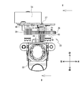
- FIG. 4 is a plan view of a mounting portion 32 and a vertical drive mechanism 33.
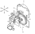
- FIG. 3 is a perspective view of a mounting portion 32 and a vertical drive mechanism 33 when cut along the line BB in FIG. 2.
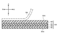
- FIG. 3 is a cross-sectional view of the first holding unit 101 when cut along the line AA of FIG. 1.
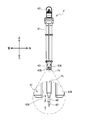
- It is a front view of the needle module P.
- It is a block diagram which shows the electric constitution of the cutting device 1A.
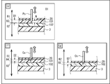
- FIG. 7 is an explanatory diagram for explaining a method of determining whether or not the first holding unit 101 is held by the second holding unit 102. It is explanatory drawing which shows a processing position.
- 6 is a table showing the relationship between the hardness of the urethane gel mat 10B and the adhesive performance during the cutting operation.
- 6 is a table showing the relationship between the hardness and the adhesive performance of the urethane gel mat 10B during the perforating operation.
- 7 is a table showing the relationship between the adhesive force and the adhesive performance of the urethane gel mat 10B during the cutting operation.
- 7 is a table showing the relationship between the adhesive force and the adhesive performance of the urethane gel mat 10B during the perforating operation.
- It is sectional drawing of 10 G of integral holding members in a modification.
- FIG. 11 is a plan view of an integrated holding member 10G in a modified example.
- the cutting device 1A is used in a state in which a cartridge 4A capable of fixing the cutting blade module C or a cartridge 4B capable of fixing the needle module P is mounted.
- the cutting device 1A can use the cutting blade Cs of the cutting blade module C to cut the sheet-shaped object 20.
- the cutting device 1A can perform perforating by piercing the object 20 with the needle Ps of the needle module P and making a plurality of holes.
- the cartridges 4A and 4B are collectively referred to as "cartridge 4".
- the lower left side, the upper right side, the lower right side, the upper left side, the upper side, and the lower side in FIG. 1 are the left side, the right side, the front side, the rear side, the upper side, and the lower side of the cutting device 1A and the cartridge 4, respectively.
- the cutting device 1A includes a main body cover 9, a platen 3, a head 5, a transport unit 7, a moving unit 8, a holding member 10, and a control unit 71 (see FIG. 6).
- the holding member 10 is conveyed in the front-rear direction by the cutting device 1A in a posture in which the longitudinal direction is the front-rear direction.
- the holding member 10 has a rectangular plate shape, and holds the object 20 on its upper surface. Details of the holding member 10 will be described later.
- the body cover 9 is provided with an opening 91, a cover 92, and an operation unit 50.
- the opening 91 is an opening provided on the front surface of the body cover 9.
- the cover 92 is a plate-shaped member that is long in the left-right direction.
- the lower end side of the cover 92 is rotatably supported by the main body cover 9. In FIG. 1, the cover 92 is opened and the opening 91 is opened.
- the operation unit 50 includes a liquid crystal display (LCD) 51, a plurality of operation switches 52, and a touch panel 53. Images including various items such as commands, illustrations, set values, and messages are displayed on the LCD 51.
- the touch panel 53 is provided on the surface of the LCD 51. The user performs a pressing operation on the touch panel 53 using either a finger or a stylus pen (hereinafter, this operation is referred to as “panel operation”). In the cutting device 1A, which item is selected is recognized corresponding to the pressed position detected by the touch panel 53. The user can use the operation switch 52 and the touch panel 53 to select a pattern displayed on the LCD 51, set various parameters, and perform an input operation.
- the platen 3 is provided inside the main body cover 9.
- the platen 3 is a plate-shaped member that extends in the left-right direction.
- the platen 3 receives the lower surface of the holding member 10 and can mount the holding member 10 holding the target object 20.
- the holding member 10 is set on the platen 3 with the opening 91 opened.
- the head 5 includes a carriage 19, a mounting portion 32, a detector 41 (see FIG. 3), and a vertical drive mechanism 33.
- the mounting portion 32 and the vertical drive mechanism 33 are arranged in front of and behind the carriage 19, respectively.
- the mounting unit 32 can mount the cartridge 4.
- the cartridge 4A with the cutting blade module C fixed is mounted, the cartridge 4A is fixed to the mounting portion 32 with the cutting blade Cs arranged at the lower end.
- the cartridge 4B is mounted with the needle module P fixed, the cartridge 4B is fixed to the mounting portion 32 with the needle Ps arranged at the lower end.
- the vertical drive mechanism 33 moves the mounting portion 32 in a direction in which the mounting portion 32 faces the holding member 10 (downward) and in a direction in which the mounting portion 32 separates from the holding member 10 (upward). As a result, the vertical drive mechanism 33 moves the cartridge 4 mounted on the mounting portion 32 in the vertical direction.
- the vertical drive mechanism 33 of this example includes a Z-axis motor 34 and a transmission member, and decelerates the rotational movement of the Z-axis motor 34 by the transmission member connected to the output shaft of the Z-axis motor 34 and converts it into vertical movement. And transmits it to the mounting portion 32, and drives the mounting portion 32 and the cartridge 4 in the vertical direction (also referred to as the Z direction). That is, the Z-axis motor 34 drives the mounting portion 32 and the cartridge 4 in the vertical direction.
- the vertical drive mechanism 33 has gears 35 and 36, a shaft 37, a plate portion 48, a pinion 38, and a rack 39 as transmission members.
- the gear 35 is fixed to the front end of the output shaft 40 of the Z-axis motor 34.
- the gear 35 meshes with the gear 36.
- the diameter of the gear 35 is smaller than the diameter of the gear 36.
- the gear 36 has a cylindrical shaft portion 46 extending in the front-rear direction.
- the shaft portion 46 of the gear 36 is inserted into the shaft 37.
- the output shaft 40 of the Z-axis motor 34 and the shaft 37 extend in the front-rear direction.
- the plate portion 48 has a disk shape slightly smaller than the diameter of the gear 36.
- the front end of the plate portion 48 is connected to the rear end of the pinion 38.
- the plate portion 48 is a member integrated with the pinion 38.
- the plate portion 48 is a member separate from the gear 36.
- the plate portion 48 and the pinion 38 can rotate independently of the rotation of the gear 36.
- the pinion 38 and the plate portion 48 are inserted into the shaft 37 in front of the gear 36.
- the pinion 38 and the plate portion 48 are rotatable relative to the shaft 37.
- the diameter of the pinion 38 is smaller than the diameter of the gears 35 and 36.
- the rack 39 extends in the vertical direction and has gear teeth on the right side that mesh with the pinion 38.
- the rack 39 is fixed to the back surface of the mounting portion 32.
- the vertical drive mechanism 33 further includes a pressure changing member 31.
- the pressure changing member 31 is a torsion spring inserted in the shaft portion 46 of the gear 36.
- the pressure changing member 31 is a member that can change the downward pressure applied to the mounting portion 32.
- the pressure changing member 31 has one end fixed to the shaft portion 46 and the other end fixed to the plate portion 48.
- the pressure changing member 31 transmits the rotation of the gear 36 to the plate portion 48.
- the pressure changing member 31 changes the downward pressure applied to the mounting portion 32 by changing the compression amount of the torsion spring according to the rotation of the gear 36.
- the detector 41 is a position sensor capable of outputting the vertical position of the mounting portion 32.
- the detector 41 is arranged on the left rear side of the mounting portion 32.
- the detector 41 can specify the vertical position of the mounting portion 32 and can output a signal indicating the specified position.
- the transport unit 7 transports the second holding unit 102 (described later) of the holding member 10 in the sub-scanning direction orthogonal to the main scanning direction described below, thereby moving the object 20 held by the holding member 10 in the sub-scanning direction.
- the main scanning direction and the sub-scanning direction in this example are the left-right direction and the front-back direction, respectively.
- the transport unit 7 is configured to be able to transport the holding member 10 set on the platen 3 in the front-back direction (also referred to as the Y direction) of the cutting device 1A.
- the transport unit 7 transports the target object 20 held by the holding member 10 in the sub-scanning direction.
- the transport unit 7 includes a drive roller 12, a pinch roller 13, a mounting frame 14, a Y-axis motor 15, and a speed reduction mechanism 17.
- a pair of side wall portions 111 and 112 are provided so as to face each other.
- the side wall portion 111 is located on the left side of the platen 3.
- the side wall portion 112 is located on the right side of the platen 3.
- the drive roller 12 and the pinch roller 13 are rotatably supported between the side wall portions 111 and 112.
- the driving roller 12 and the pinch roller 13 transfer the holding member 10.
- the drive roller 12 and the pinch roller 13 extend in the left-right direction (also referred to as the X direction) of the cutting device 1A and are arranged side by side in the up-down direction.
- a roller portion (not shown) is provided on the left side of the pinch roller 13, and a roller portion 131 is provided on the right side.
- the mounting frame 14 is fixed to the outer surface side (right side) of the side wall 112.
- a Y-axis motor 15 is attached to the attachment frame 14.
- the output shaft of the Y-axis motor 15 is fixed to a drive gear (not shown) of the reduction mechanism 17.
- the drive gear meshes with a driven gear (not shown).
- the driven gear is fixed to the tip of the right end of the drive roller 12.
- the left outside portion of the holding member 10 is sandwiched between the drive roller 12 and the roller portion (not shown) on the left side of the pinch roller 13.
- the right outer side portion of the holding member 10 is sandwiched between the drive roller 12 and the roller portion 131.
- the Y-axis motor 15 is driven to rotate normally or reversely, the rotational movement of the Y-axis motor 15 is transmitted to the drive roller 12 via the reduction mechanism 17. That is, the Y-axis motor 15 drives the drive roller 12. As a result, the holding member 10 is transported backward or forward.
- the moving unit 8 is configured to be able to move the head 5 in a direction intersecting the transport direction of the holding member 10, that is, the X direction. That is, the moving direction of the head 5 is orthogonal to the carrying direction of the holding member 10.
- the moving unit 8 includes a pair of upper and lower guide rails 21, 22, a mounting frame 24, an X-axis motor 25, a drive gear 27 and a driven gear 29 as a reduction mechanism, a transmission mechanism 30, and the like.
- the guide rails 21 and 22 are fixed between the side wall portions 111 and 112.
- the guide rails 21 and 22 are located rearward and upward with respect to the pinch roller 13.
- the guide rails 21 and 22 extend substantially parallel to the pinch roller 13, that is, in the X direction.
- the carriage 19 of the head 5 is supported by the guide rails 21 and 22 so as to be movable in the X direction along the guide rails 21 and 22.
- the mounting frame 24 is fixed to the outer surface side (left side) of the side wall 111.
- the X-axis motor 25 is mounted rearward of the mounting frame 24 and faces downward.
- the drive gear 27 is fixed to the output shaft of the X-axis motor 25.
- the driven gear 29 meshes with the drive gear 27.
- the transmission mechanism 30 has a pair of left and right timing pulleys (not shown) and an endless timing belt mounted on the pair of left and right timing pulleys.
- One of the timing pulleys 28 is provided on the mounting frame 24 so as to be rotatable integrally with the driven gear 29.
- the other timing pulley is provided on the mounting frame 14.
- the timing belt extends in the X direction and is connected to the carriage 19.
- the moving unit 8 moves the cartridge 4 mounted on the mounting unit 32 of the head 5 in the main scanning direction.
- the moving unit 8 converts the rotational movement of the X-axis motor 25 into movement in the X direction and transmits the movement to the carriage 19.
- the X-axis motor 25 is driven to rotate normally or reversely, the rotational movement of the X-axis motor 25 is transmitted to the timing belt via the drive gear 27, the driven gear 29, and the timing pulley 28.
- the carriage 19 is moved leftward or rightward. That is, the transport unit 7 and the moving unit 8 move the mounting unit 32 with respect to the holding member 10 in the front-rear direction (sub-scanning direction) and the left-right direction (main-scanning direction).
- the holding member 10 will be described with reference to FIGS. 1 and 4. As shown in FIG. 1, the holding member 10 has a first holding portion 101 and a second holding portion 102. The first holding unit 101 and the second holding unit 102 each have a plate shape.
- the first holding unit 101 has a substantially rectangular shape and is orthogonal to the vertical direction.
- a protruding portion 10T that protrudes rearward is provided at the right rear end portion of the first holding portion 101.
- the first holding unit 101 has a cross-sectional structure in which a urethane gel mat 10B, a base film 10C, an adhesive layer 10D, and a non-adhesive film 10E are laminated in this order from the top.
- the base film 10C has a film shape and serves as a base for the first holding unit 101.
- the base film 10C is made of PET (polyethylene terephthalate).
- the material of the base film 10C is not limited to PET, and other materials (for example, polyvinyl chloride, polypropylene, etc.) may be used.
- the urethane gel mat 10B is formed on the upper surface of the base film 10C.
- the urethane gel mat 10B is composed of a self-adhesive elastomer gel, more specifically, a urethane elastomer gel.
- the thickness of the urethane gel mat 10B is about 1 mm.
- the Asker C hardness of the urethane gel mat 10B is 20 or more and 40 or less, and more preferably 25 or more and 35 or less.
- the adhesive strength of the urethane gel mat 10B is 0.5 N/25 mm or more and 6.0 N/25 mm or less at 20 degrees, and more preferably 1.5 N/25 mm or more and 4.0 N/25 mm or less at 20 degrees.
- the upper surface of the urethane gel mat 10B corresponds to the upper surface of the first holding unit 101. Hereinafter, this surface is referred to as "first surface 101A".
- the first holding unit 101 can hold the target object 20 on the first surface 101A by attaching the target object 20 to the first surface 101A by the self-adhesiveness of the urethane gel mat 10B.
- the non-adhesive film 10E is arranged on the lower surface of the base film 10C.
- the non-adhesive film 10E is made of PET.
- the non-adhesive film 10E has non-adhesiveness and is difficult to be attached to other films or the like. Therefore, the upper surface of the non-adhesive film 10E is attached to the lower surface of the base film 10C by the adhesive of the adhesive layer 10D.
- the lower surface of the non-adhesive film 10E corresponds to the lower surface of the first holding unit 101, in other words, the surface opposite to the first surface 101A of the first holding unit 101.
- this surface is referred to as "second surface 101B".
- the second surface 101B is non-adhesive because the non-adhesive film 10E is exposed.
- the cover film 10A may be attached to the first surface 101A of the first holding unit 101.
- the cover film 10A has a film shape.
- the cover film 10A prevents other objects from sticking to the urethane gel mat 10B when the first holding portion 101 is not used.
- the cover film 10A can be peeled off from the urethane gel mat 10B.
- the first holding unit 101 is used with the cover film 10A peeled off from the first surface 101A during use.
- the urethane gel mat 10B is exposed when the cover film 10A is peeled off from the first surface 101A. In this state, the first holding unit 101 can attach and hold the target object 20 on the first surface 101A.
- the second holding unit 102 has a rectangular shape and is orthogonal to the vertical direction.
- the second holding portion 102 is made of, for example, a synthetic resin material.
- the hardness of the second holding portion 102 is higher than the hardness of the urethane gel mat 10B of the first holding portion 101.
- the lengths of the second holding portion 102 in the front-rear direction and the left-right direction are longer than the lengths of the first holding portion 101 in the front-rear direction and the left-right direction, respectively.
- the peripheral end portion of the first holding member 101 is located inside the peripheral end portion of the second holding portion 102.
- the first holding portion 101 is surrounded by the peripheral end portion of the second holding portion 102.
- the second holding unit 102 has a larger area than the first holding unit 101.
- the upper surface of the second holding portion 102 is referred to as "third surface 102A”, and the lower surface of the second holding portion 102 is referred to as "fourth surface 102B”.
- a region of the third surface 102A of the second holding unit 102 excluding the peripheral portion (hereinafter, referred to as “adhesive region”) has adhesiveness.
- the second holding unit 102 attaches the first holding unit 101 to the third surface 102A by adhering the second surface 101B (see FIG. 4) of the first holding unit 101 to the adhesive area of the third surface 102A. Can be held at.
- the transport unit 7 transports the second holding unit 102 that holds the first holding unit 101 to relatively move the mounting unit 32 and the first holding unit 101 in the front-rear direction. Thereby, the transport unit 7 can relatively move the object 20 held on the first surface 101A of the first holding unit 101 and the mounting unit 32 in the front-rear direction.
- the second holding unit 102 can detach the first holding unit 101 by peeling the first holding unit 101 from the adhesive area of the third surface 102A. Furthermore, the second holding unit 102 can directly hold the target object 20 on the third surface 102A by attaching the target object 20 to the adhesive area of the third surface 102A in a state where the first holding unit 101 is detached. ..
- the transport unit 7 can relatively move the target object 20 and the mounting unit 32 in the front-rear direction by transporting the second holding unit 102 in a state of directly holding the target object 20.
- detection areas Rd and Rn are defined in the holding member 10.
- the detection region Rd is a region in which the protrusion 10T of the first holding unit 101 and the second holding unit 102 are stacked and arranged while the first holding unit 101 is held by the second holding unit 102.
- the protrusion 10T of the first holding part 101 is not arranged in the detection region Rd, but only the second holding part 102 is arranged.
- the detection area Rn is located to the left of the detection area Rd. In the detection area Rn, regardless of whether or not the first holding unit 101 is held by the second holding unit 102, only the second holding unit 102 is always arranged.
- the needle module P is used by being attached to the cartridge 4B (see FIG. 1).
- the needle module P has a base portion 61, a knob 62, a cover 63, and a needle Ps.
- the base 61 has a substantially columnar shape and extends in the vertical direction.
- the knob 62 has a plate shape and is provided on the upper end of the base 61.
- the knob 62 is gripped by the user when the needle module P is attached to or detached from the cartridge 4B.
- the cover 63 is provided at the lower end of the base 61.
- the cover 63 is composed of a cylindrical body 63A and a notch 63B.
- the cylindrical body 63A extends downward from the lower end of the base 61.
- the notch 63B is provided on the lower surface of the cylindrical body 63A.
- the notch 63B is a concave portion that is recessed upward.
- the notch 63B extends in the front-rear direction from the front end to the rear end at the lower end of the cylindrical body 63A.
- the needle Ps is held in the base 61.
- the axis of the needle Ps extends vertically.
- the tip of the needle Ps projects downward from the bottom surface of the notch 63B of the cover 63.
- the portion of the needle Ps that projects from the bottom surface of the notch 63B has a first portion 66 and a second portion 67.
- the diameter of the first portion 66 is approximately 0.4 mm to 0.8 mm in the axial direction and is the same.
- the second portion 67 is located closer to the tip side than the first portion 66.
- the diameter of the second portion 67 decreases in the axial direction toward the tip.
- the axial length N of the second portion 67 is about 1 mm.
- the tip of the needle Ps projects below the lower end of the cylindrical body 63A of the cover 63.
- the thickness of the urethane gel mat 10B of the first holding portion 101 is 1 mm, the total thickness of the first holding portion 101 is larger than 1 mm. Therefore, the thickness (>1 mm) of the first holding portion 101 is larger than the axial length N (1 mm) of the second portion 67.
- the cutting device 1A includes a control unit 71, a ROM 72, a RAM 73, and an input/output (I/O) interface 75.
- the control unit 71 is electrically connected to the ROM 72, the RAM 73, and the I/O interface 75.
- the control unit 71 is a CPU that controls the main control of the cutting device 1A together with the ROM 72 and the RAM 73.
- the ROM 72 stores various programs for operating the cutting device 1A.
- the RAM 73 temporarily stores the calculation result and the like processed by the control unit 71.
- the I/O interface 75 is further connected to a flash memory 74, operation switches 52, touch panel 53, LCD 51, detector 41, and drive circuits 77 to 79.
- the flash memory 74 is a non-volatile storage element that stores various parameters, cutting data, plot data, and the like.
- the cutting data indicates control conditions of the vertical drive mechanism 33, the transport unit 7, and the moving unit 8 for cutting the target object 20 by the cutting blade Cs to cut out a desired shape.
- the cutting data includes start coordinates and end coordinates for controlling the transport unit 7 and the moving unit 8.
- the plot data indicates control conditions of the vertical drive mechanism 33, the transport unit 7, and the moving unit 8 when perforating is performed by making a hole in the object 20 with the needle Ps.
- the plot data includes a plurality of plot coordinates for controlling the transport unit 7 and the moving unit 8.
- the origin of the coordinate system is the point to the left rear of the area that can be cut or punched.
- the left-right direction is set to the X direction, and the front-back direction is set to the Y direction.
- the cutting data and the plot data are stored in the flash memory 74 for each pattern, pattern, or the like (hereinafter referred to as “object”) to be cut or perforated.
- the LCD 51 can inform various instructions.
- the detector 41 outputs a signal indicating the vertical position of the mounting portion 32.
- the drive circuits 77 to 79 drive the Y-axis motor 15, the X-axis motor 25, and the Z-axis motor 34, respectively.
- the control unit 71 drives the Y-axis motor 15, the X-axis motor 25, the Z-axis motor 34, and the like via the drive circuits 77 to 79, and controls the transport unit 7, the moving unit 8, and the vertical drive mechanism 33. As a result, the control unit 71 relatively moves the mounting unit 32 and the holding member 10.
- the needle Ps penetrates the object 20 held by the holding member 10 and a hole is made in the object 20.
- the control unit 71 controls the vertical drive mechanism 33 to move the mounting unit 32 upward to a position where the needle Ps of the needle module P is separated from the target object 20 upward.
- the above-described perforating operation can be executed with the first holding unit 101 held by the second holding unit 102 and the target object 20 held by the first holding unit 101.
- the concave portion can be eliminated by the rubber elasticity of the urethane gel mat 10B.
- the wall surfaces of the recesses adhere to each other, so that the recesses can be more effectively eliminated.
- the above-described perforating operation cannot be performed in the state where the target object 20 is directly held by the second holding unit 102.
- the reason is that the second holding portion 102 is harder than the first holding portion 101, and therefore the needle Ps is not attached to the second holding portion 102 to the extent that it is possible to make a sufficiently large hole in the object 20 with the needle Ps. This is because you cannot pierce deeply.
- ⁇ Outline of operation of the cutting device 1A (cutting operation)> An outline of an operation (hereinafter, referred to as “cutting operation”) in which the cutting device 1A cuts the target object 20 with the cutting blade Cs according to the cutting data will be described.
- the control unit 71 controls the transport unit 7 and the moving unit 8 in a state where the cutting blade Cs of the cutting blade module C is separated upward from the object 20 and attaches the cutting blade Cs to the start position indicated by the start coordinates of the cutting data.
- the part 32 is moved.
- the control unit 71 controls the up-and-down drive mechanism 33 to move the mounting unit 32 downward to a position where the cutting blade Cs of the cutting blade module C contacts the holding member 10.
- control unit 71 controls the transport unit 7 and the moving unit 8 to relatively move the holding member 10 and the mounting unit 32 in the X direction and the Y direction to the end position indicated by the end coordinates of the cutting data.
- control unit 71 controls the up-and-down drive mechanism 33 to move the mounting unit 32 upward to a position where the cutting blade Cs of the cutting blade module C is separated from the object 20 upward.
- the object 20 held by the holding member 10 is cut by the cutting blade Cs by performing the above processing for the number of start coordinates and end coordinates included in the cutting data.
- the above cutting operation can be executed in a state where the first holding unit 101 is held by the second holding unit 102 and the target object 20 is held by the first holding unit 101.
- the notch can be eliminated by the rubber elasticity of the urethane gel mat 10B.
- the wall surfaces of the recesses adhere to each other, so that the recesses can be more effectively eliminated.
- the above cutting operation can be executed even when the target object 20 is directly held by the second holding unit 102. This is because the depth of the cut formed by the cutting blade Cs during the cutting operation is set smaller than the depth of the recess formed by the needle Ps during the perforating operation. The reason is that when the cutting blade Cs is deeply inserted into the holding member 10, a large moving load is required when the cutting blade Cs and the holding member 10 are relatively moved by the transport unit 7 and the moving unit 8, and thus the relative movement cannot be performed. This is because.
- the holding member 10 that holds the object 20 is either the first holding unit 101 or the second holding unit 102, the cutting blade Cs and the holding member 10 are held in the state where the cutting blade Cs enters the holding member 10. It will be possible to move relative.
- the control unit 71 of the cutting device 1A detects that the cutting blade Cs or the needle Ps comes into contact with the holding member 10 when the mounting unit 32 mounted with the cartridge 4 moves downward by the following method.
- the control unit 71 moves the mounting unit 32 downward by rotating the Z-axis motor 34 of the vertical drive mechanism 33. At this time, as shown in FIGS. 2 and 3, the output shaft 40 of the Z-axis motor 34 and the gears 35 and 36 rotate, and the pressure changing member 31 transmits the rotation of the gear 36 to the plate portion 48.
- the upward pressure is not applied to the mounting unit 32. Therefore, as the rotation of the gear 36 is transmitted to the plate portion 48 by the pressure changing member 31, the plate portion 48 and the pinion 38 rotate as much as the rotation of the gear 36.
- the Z-axis motor 34 is a pulse motor, and there is a correlation between the number of pulses input to the Z-axis motor 34 and the downward pressure acting on the mounting portion 32 from the pressure changing member 31. Therefore, the control unit 71 counts the number of pulses input to the Z-axis motor 34 when moving the mounting unit 32 downward, and at the same time, based on the signal output from the detector 41, the position of the mounting unit 32. To get The control unit 71 identifies the timing when the relationship between the number of pulses and the position of the mounting unit 32 has changed, as the timing when the cutting blade Cs or the needle Ps contacts the holding member 10. Further, the control unit 71 specifies the vertical position (hereinafter, referred to as “contact position”) of the tip of the cutting blade Cs or the needle Ps that contacts the holding member 10 based on the position of the mounting unit 32 at this timing.
- the main processing executed by the control unit 71 of the cutting device 1A will be described with reference to FIG. 7.
- the main process is started by the control unit 71 reading and executing the program stored in the ROM 72 when an operation of turning on the power of the cutting device 1A is executed.
- the control unit 71 determines by the following method whether or not the first holding unit 101 is held by the second holding unit 102 (S11).
- the control unit 71 controls the transport unit 7 and the moving unit 8 to move the mounting unit 32 with the cartridge 4 mounted above the detection region Rd (see FIG. 1) of the holding member 10.
- the control unit 71 controls the vertical drive mechanism 33 to move the mounting unit 32 downward.
- the control unit 71 causes the cutting blade Cs or the needle Ps to move to the holding member 10 based on the number of pulses input to the Z-axis motor 34 when moving the mounting unit 32 downward and the signal output from the detector 41.
- the vertical position of the mounting portion 32 when contacted is specified.
- the control unit 71 causes the tip of the cutting blade Cs or the needle Ps to hold the holding member based on the specified position of the mounting unit 32 and the vertical distance between the mounting unit 32 and the cutting blade Cs or the needle Ps.
- the vertical position of the tip of the cutting blade Cs or the needle Ps when it contacts 10 is specified as the contact position Qd.
- the control unit 71 controls the vertical drive mechanism 33 to move the mounting unit 32 upward to the position where the cutting blade Cs or the needle Ps is separated from the holding member 10 upward.
- first process the above process in which the contact position Qd is specified is referred to as “first process”.
- control unit 71 controls the transport unit 7 and the moving unit 8 to move the mounting unit 32 with the cartridge 4 mounted above the detection region Rn (see FIG. 1) of the holding member 10.
- the control unit 71 controls the vertical drive mechanism 33 to move the mounting unit 32 downward.
- the control unit 71 sets the vertical position of the tip of the cutting blade Cs or the needle Ps when the tip of the cutting blade Cs or the needle Ps contacts the holding member 10 as the contact position Qn. Identify.
- the control unit 71 controls the vertical drive mechanism 33 to move the mounting unit 32 upward to the position where the cutting blade Cs or the needle Ps is separated from the holding member 10 upward.
- the above process in which the contact position Qn is specified is referred to as a "second process”.
- the cutting blade Cs or the cutting blade Cs on the first surface 101A of the protrusion 10T (see FIG. 1) of the first holding unit 101 or The needle Ps comes into contact (see FIG. 8A).
- the contact position Qd in this case is referred to as a first position B1 as shown in FIG.
- the cutting blade Cs or the needle Ps comes into contact with the third surface 102A of the second holding part 102 in the first step (Fig. 8(b)).
- the contact position Qd in this case is referred to as a second position B2 as shown in FIG.
- the second position B2 is arranged below the first position B1.
- the cutting blade Cs or the needle Ps contacts the third surface 102A of the second holding unit 102 regardless of whether or not the first holding unit 101 is held by the second holding unit 102. (See FIGS. 8C and 8D).
- the contact position Qn is the second position B2 as shown in FIGS. 8C and 8D.
- the control unit 71 sets the second position. It is determined that the first holding unit 101 is held by the holding unit 102 (S11: YES). On the other hand, when the contact position Qd specified in the first step and the contact position Qn specified in the second step match (see FIGS. 8B and 8D), the control unit 71 holds the second position. It is determined that the first holding unit 101 is not held by the unit 102 (S11: NO).
- the control unit 71 determines that the first holding unit 101 is held by the second holding unit 102 (S11: YES), when the mounting unit 32 is moved in the vertical direction.
- the first position B1 identified as the contact position Qd in the first step is set as the reference position serving as the reference (S13).
- the control unit 71 advances the process to S17.
- the control unit 71 sets the contact positions Qn and Qd in the first step and the second step as the reference position.
- the second position B2 which is specified and is arranged below the first position B1 is set (S15). The control unit 71 advances the process to S17.
- the user mounts the cartridge 4B to which the needle module P including the needle Ps is fixed in the mounting portion 32 of the cutting device 1A.
- the needle Ps of the cartridge 4B is arranged so as to be separated from the holding member 10 upward.
- the user uses the first holding unit 101 to punch a hole in the object 20 and perform perforating, so that the first holding unit 101 is attached to the adhesive area of the third surface 102A of the second holding unit 102.
- the second surface 101 ⁇ /b>B is brought into contact with the first surface 101 ⁇ /b>B, and the first holding portion 101 is held by the second holding portion 102.
- the user brings the object 20 into contact with the first surface 101 ⁇ /b>A of the first holding unit 101 and attaches it, and holds the object 20 by the first holding unit 101. After that, the user performs a panel operation for designating an object and instructing the start of the perforating operation.
- the user mounts the cartridge 4A, to which the cutting blade module C including the cutting blade Cs is fixed, in the mounting portion 32 of the cutting device 1A.
- the cutting blade Cs of the cartridge 4A is arranged so as to be separated upward with respect to the holding member 10.
- the user cuts the object 20 using the first holding unit 101
- the user brings the second surface 101B of the first holding unit 101 into contact with the adhesive area of the third surface 102A of the second holding unit 102.
- the first holder 101 is attached and held by the second holder 102.
- the user brings the object 20 into contact with the first surface 101 ⁇ /b>A of the first holding unit 101 and attaches it, and holds the object 20 by the first holding unit 101.
- the user cuts the target object 20 without using the first holding unit 101
- the user touches and sticks the target object 20 to the adhesive area of the third surface 102A of the second holding unit 102, and then the second holding unit.
- the object 20 is held by the unit 102.
- the user performs a panel operation for designating the object and instructing the start of the cutting operation.
- the control unit 71 determines whether an instruction to start the perforating operation has been input by the panel operation (S17). When it is determined that the instruction for starting the perforating operation is input (S17: YES), the control unit 71 reads the plot data corresponding to the specified object from the flash memory 74 and acquires it (S19). ).
- the control unit 71 determines whether the first position B1 is set as the reference position (see S13) (S21). When the control unit 71 determines that the first position B1 is set as the reference position (S21: YES), the second holding unit 102 holds the first holding unit 101, and the first holding unit 101 also holds the first holding unit 101. Since the target object 20 is held, it is determined that the perforating operation can be executed. In this case, the control unit 71 calculates the third position B3, which is spaced downward by the distance D1 from the first position B1 set as the reference position (see FIG. 9E).
- the control unit 71 sets the calculated third position B3 as the position of the tip of the needle Ps when the mounting unit 32 is moved downward to make a hole in the target object 20 with the needle Ps by the perforating operation. Yes (S23). The control unit 71 advances the process to S37.
- the distance D1 is smaller than the thickness of the first holding unit 101. Therefore, the third position B3 is arranged above the second position B2 which is the position of the third surface 102A of the second holding unit 102. Therefore, when the needle Ps is stabbed into the first holding portion 101 in accordance with the perforating operation, the tip of the needle Ps has a second surface 101B of the first holding portion 101 and a third surface 102A of the second holding portion 102. It is located above the contact area with. Therefore, the needle Ps does not penetrate the first holding unit 101.
- the distance D1 is longer than the axial length N of the second portion 67 of the needle Ps (see FIG. 9(e)). Therefore, a hole having substantially the same diameter as the diameter of the first portion 66 of the needle Ps is made in the object 20 according to the perforating operation.
- control unit 71 determines that the second position B2 is set as the reference position (see S15) (S21: NO), the object 20 is directly held by the second holding unit 102, so It is determined that the perforating operation cannot be executed. In this case, the control unit 71 displays on the LCD 51 an error screen notifying that the perforating operation cannot be executed (S25). The control unit 71 ends the main processing.
- control unit 71 determines whether the instruction for starting the perforating operation is not input (S17: NO).
- the process proceeds to S27.
- the control unit 71 determines whether an instruction to start the cutting operation has been input by the panel operation (S27). When it is determined that the instruction to start the cutting operation is input (S27: YES), the control unit 71 reads the cutting data corresponding to the specified object from the flash memory 74 and acquires it (S29).
- the control unit 71 determines whether the first position B1 is set as the reference position (see S13) (S31). When the control unit 71 determines that the first position B1 is set as the reference position (S31: YES), the second holding unit 102 holds the first holding unit 101, and the first holding unit 101 also holds the first holding unit 101. It is determined that the target object 20 is held and the cutting operation can be executed. In this case, the control unit 71 calculates the fourth position B4, which is spaced downward by the distance D2 from the first position B1 set as the reference position (see FIG. 9F).
- the control unit 71 sets the calculated fourth position B4 as the position of the tip of the cutting blade Cs when the mounting unit 32 is moved downward to cut the object 20 with the cutting blade Cs by the cutting operation. (S33). The control unit 71 advances the process to S37.
- the fourth position B4 is arranged above the third position B3, which is the position of the tip of the needle Ps when the needle Ps is stuck in the first holding portion 101 in accordance with the perforating operation (FIG. 9). (See (e) and (f)).
- the control unit 71 determines that the second position B2 is set as the reference position (see S15) (S31: NO), the object 20 is directly held by the second holding unit 102 and is cut. It is determined that the operation can be executed. In this case, the control unit 71 calculates the fifth position B5, which is spaced downward by the distance D2 from the second position B2 set as the reference position (see FIG. 9G). The control unit 71 sets the calculated fifth position B5 as the position of the tip of the cutting blade Cs when the mounting unit 32 is moved downward to cut the target object 20 with the cutting blade Cs by the cutting operation. (S35). The control unit 71 advances the process to S37.
- the position of the tip of the cutting blade Cs when the mounting portion 32 is moved downward for cutting is collectively referred to as a "processing position".
- the processing position is set to the third position B3 (see FIG. 9(e)) by the process of S23, the fourth position B4 (see FIG. 9(f)) by the process of S33, and the fifth position by the process of S35. This means that the position B5 has been set (see FIG. 9(g)).
- the control unit 71 executes a perforating operation or a disconnecting operation (S37).
- the control unit 71 controls the transport unit 7 and the moving unit 8 to move the mounting unit 32 to the plot position indicated by the plot coordinates of the plot data.
- the control unit 71 controls the vertical drive mechanism 33 to move the mounting unit 32 downward until the tip of the needle Ps of the needle module P reaches the processing position (third position B3).
- the first holder 101 is held by the second holder 102, and the object 20 is held by the first holder 101, so that the object 20 is perforated.
- control unit 71 controls the up-and-down drive mechanism 33 to move the mounting unit 32 upward to the position where the needle Ps of the needle module P is separated upward from the holding member 10.
- the above process is executed for the number of plot coordinates included in the plot data acquired by the process of S19.
- the control unit 71 controls the transport unit 7 and the moving unit 8 to move the mounting unit 32 to the start position indicated by the start coordinates of the cutting data.
- the control unit 71 controls the vertical drive mechanism 33 to move the mounting unit 32 downward until the tip of the cutting blade Cs of the cutting blade module C reaches the processing position (the fourth position B4 or the fifth position B5). ..
- the processing position is the fourth position B4 in a state where the first holding unit 101 is held by the second holding unit 102 and the target object 20 is held by the first holding unit 101, and the second holding unit 102 is The processing position is the fifth position B5 in the state where the object 20 is directly held by.
- control unit 71 controls the transport unit 7 and the moving unit 8 to relatively move the holding member 10 and the mounting unit 32 in the X direction and the Y direction to the end position indicated by the end coordinates of the cutting data. After that, the control unit 71 controls the vertical drive mechanism 33 to move the mounting unit 32 upward to a position where the cutting blade Cs of the cutting blade module C is separated from the holding member 10 upward.
- the above process is executed for the number of start coordinates and end coordinates included in the cut data acquired in the process of S29.
- control unit 71 When the perforating operation or the disconnecting operation is completed by the processing of S37, the control unit 71 returns the processing to S17.
- the control unit 71 executes the cutting operation (S29 to S35, S37) and cuts the target object 20 held by the first holding unit 101 with the cutting blade Cs. In this case, the state in which the object 20 is held by the first holding unit 101 is maintained from the start of the perforating operation to the end of the cutting operation.
- the user performs the perforating operation on the target object 20 that is held by the first holding unit 101 and cut by the cutting blade Cs after the execution of the cutting operation (S29 to S35, S37).
- the cartridge 4A to which the cutting blade module C including the cutting blade Cs is fixed is removed from the mounting portion 32, and instead, the cartridge 4B to which the needle module P including the needle Ps is fixed is mounted in the mounting portion 32.
- the control unit 71 performs the perforating operation (S21 to S23, S37) and punches the object 20 held by the first holding unit 101 with the needle Ps. In this case, the state in which the target object 20 is held by the first holding unit 101 is maintained from the start of the cutting operation to the end of the perforating operation.
- the control unit 71 When the instruction for starting the perforating operation and the cutting operation is not input by the panel operation (S17:NO, S27:NO), the control unit 71 gives an instruction for ending the perforating operation and the cutting operation. It is determined whether is input by the panel operation (S39). When determining that the instruction for ending the perforating operation and the cutting operation has not been input by the panel operation (S39: NO), the control unit 71 returns the process to S17. When determining that the instruction for ending the perforating operation and the cutting operation has been input by the panel operation (S39: YES), the control unit 71 ends the main processing.
- FIG. 10 and 11 show the adhesive performance of the urethane gel mat 10B during the cutting operation (see FIG. 10) or the perforating operation (see FIG. 11) of various objects (plain paper, parchment paper, cloth).
- the results evaluated for each Asker C hardness of 10B (see FIG. 4) (hereinafter, simply referred to as “hardness”) are shown.
- a urethane gel mat 10B having an adhesive force of 1.5 (N/25 mm) was used.
- the adhesive performance was measured in three grades of “ ⁇ ” (good), “ ⁇ ” (generally good), and “x” (somewhat poor).
- the evaluation standard is (1) When the object 20 held by the urethane gel mat 10B is processed by a cutting operation or a perforating operation, whether the object 20 can be held by the urethane gel mat 10B, and (2) When the object 20 is peeled from the urethane gel mat 10B after the cutting operation or the perforating operation, it is determined whether the object 20 can be peeled without curling.
- FIG. 10 (during the cutting operation) and FIG. 11 (during the perforating operation) are different in that the evaluated object 20 includes cloth. The cloth 20 is included in the target object 20 that is the target of the cutting operation (see FIG. 10 ), but the target object 20 that is the target of the perforating operation does not include the cloth (see FIG. 11 ).
- cloth is not usually used as the target object 20 that is the target of the perforating operation.
- the smaller the hardness the greater the adhesive performance, and the object 20 can be strongly attached to the urethane gel mat 10B.
- the hardness is too low, the object 20 becomes difficult to peel off from the urethane gel mat 10B, which is not preferable.
- the object 20 when the hardness of the urethane gel mat 10B was set to 25 to 30, the object 20 (parchment paper) was more easily attached to the urethane gel mat 10B and was easily peeled off ( ⁇ ).
- the object 20 when a cloth is used as the object 20, when the hardness of the urethane gel mat 10B is set to 20 to 30, the object 20 (cloth) is easily attached to the urethane gel mat 10B and is peeled off. The result was easy ( ⁇ or ⁇ ).
- the hardness of the urethane gel mat 10B when the hardness of the urethane gel mat 10B was set to 20 to 25, the object 20 (cloth) was more easily attached to the urethane gel mat 10B and easily peeled off ( ⁇ ).
- the processing method cutting operation or perforating operation
- the type of the target object 20 can be changed. It has been clarified that the urethane gel mat 10B that is easy to stick and easy to peel can always be formed regardless of the above.
- the greater the adhesive force the stronger the object 20 can be attached to the urethane gel mat 10B.
- the adhesive force is too large, the object 20 is unlikely to peel off from the urethane gel mat 10B, which is not preferable.
- the urethane gel mat 10B has On the other hand, the result ( ⁇ or ⁇ ) was that the object 20 (plain paper) was easy to stick and peeled off easily. Further, when the adhesive strength of the urethane gel mat 10B is 0.75 to 1.5, the object 20 (plain paper) is more easily attached to the urethane gel mat 10B and is easily peeled off ( ⁇ ).
- the adhesive strength of the urethane gel mat 10B is 0.5 N/25 mm or more and 6.0 N/25 mm or less in an environment of 20° C., more preferably 0.75 N/25 mm or more 4.0 N at 20° C. It has been clarified that the urethane gel mat 10B which is easily stuck and easily peeled can be always formed regardless of the processing method (cutting operation or perforating operation) and the type of the target object 20 by setting /25 mm or less.
- the object 20 is held on the first surface 101A of the first holding portion 101 including the urethane gel mat 10B made of an elastomer gel. Since the elastomer gel has self-adhesiveness, the object 20 is favorably held on the first surface 101A of the first holding portion 101 where the urethane gel mat 10B is exposed. Further, since the elastomer gel has rubber elasticity, the concave portion formed in the first holding portion 101 when the cutting blade Cs or the needle Ps penetrates the object and pierces the first holding portion 101 is the first holding portion.
- the cutting device 1A controls the up-and-down drive mechanism 33, the transport unit 7, and the moving unit 8 to make a plurality of holes with the needle Ps for the target object 20 appropriately held by the first holding unit 101. Can be opened or cut with the cutting blade Cs. Therefore, the cutting device 1A can appropriately perform the cutting operation and the perforating operation.
- the urethane gel mat 10B of the first holding portion 101 is made of urethane elastomer gel.
- the urethane elastomer gel has excellent properties in terms of rubber elasticity, mechanical strength, abrasion resistance, bending resistance and the like. Therefore, the cutting device 1A can further maintain the holding performance of the first holding unit 101 better than the case where a material other than the urethane elastomer gel is used as the material of the urethane gel mat 10B of the first holding unit 101. Further, the cutting device 1A can enhance the durability of the first holding unit 101. Further, the cutting device 1A can prevent the first holding unit 101 from being deformed in the process of making a hole in the target object 20 or in the process of cutting the target object 20.
- the second holding portion 102 of the holding member 10 has a larger area than the first holding portion 101.
- the adhesive area of the third surface 102A of the second holding unit 102 has adhesiveness. Therefore, the second holding unit 102 brings the adhesive region of the third surface 102A into contact with the second surface 101B of the first holding unit 101 to hold the first holding unit 101 well, and to the second holding unit 102. As a result, the first holding unit 101 can be prevented from shifting. Further, the non-adhesive film 10E is exposed on the second surface 101B of the first holding portion 101, and has non-adhesiveness. Therefore, the cutting device 1 ⁇ /b>A can process the target object 20 with the first holding unit 101 detached from the second holding unit 102. Therefore, for example, the cutting device 1A can easily remove the first holding unit 101 from the second holding unit 102 when processing the object 20 by a processing method (for example, a cutting operation) that does not require the first holding unit 101. it can.
- a processing method for example, a cutting operation
- the target object 20 is held by the first holding unit 101.
- the target object 20 is directly held by the second holding unit 102.
- the vertical position of the target object 20 is different. Therefore, when the cutting device 1A performs the cutting operation, the cutting blade Cs when the mounting portion 32 is moved downward depending on whether the first holding portion 101 is held by the second holding portion 102 or not. The position of the tip (processing position) needs to be adjusted.
- the cutting device 1A determines whether or not the first holding unit 101 is held by the second holding unit 102 (S11), and moves the mounting unit 32 in the vertical direction according to the determination result.
- the reference position serving as the reference is changed (S13, S15).
- the cutting device 1A changes the processing position according to the reference position (S29, S31). Therefore, the cutting device 1A can appropriately cut the object 20 regardless of whether the first holding unit 101 is used.
- the Asker C hardness of the urethane gel mat 10B of the first holding portion 101 is 20 or more and 40 or less. In this case, the first holding unit 101 can prevent the target 20 from being displaced from the first holding unit 101 during processing of the target 20. Further, the first holding portion 101 allows the object 20 to be easily removed from the first holding portion 101 after processing.
- the Asker C hardness of the urethane gel mat 10B of the first holding portion 101 is more preferably 25 or more and 35 or less. In this case, the first holding unit 101 can further favorably prevent the object 20 from being displaced from the first holding unit 101 during processing. Further, the first holding unit 101 can more easily remove the object 20 from the first holding unit 101 after processing.
- the adhesive strength of the urethane gel mat 10B of the first holding portion 101 is 0.5 N/25 mm or more and 6.0 N/25 mm or less at 20°C.
- the first holding unit 101 can prevent the target 20 from being displaced from the first holding unit 101 during processing of the target 20. Further, the first holding portion 101 allows the object 20 to be easily removed from the first holding portion 101 after processing.
- the adhesive force of the first holding portion 101 is more preferably 0.75 N/25 mm or more and 4.0 N/25 mm or less at 20°C. In this case, the first holding unit 101 can further favorably prevent the object 20 from being displaced from the first holding unit 101 during processing. Further, the first holding unit 101 can more easily remove the object 20 from the first holding unit 101 after processing.
- the needle Ps has a first portion 66 having the same diameter in the axial direction, and a second portion 67 located closer to the tip end than the first portion 66 and having a diameter that decreases in the axial direction toward the tip.
- the second portion 67 of the needle Ps pierces the first holding portion 101.
- the thickness of the urethane gel mat 10B of the first holding portion 101 is substantially the same as the axial length N of the second portion 67 of the needle Ps.
- the thickness of the first holding portion 101 is larger than the axial length N of the second portion 67 of the needle Ps. Therefore, the cutting device 1A can reduce the possibility that the needle Ps penetrating the object 20 and piercing the first holding unit 101 will penetrate the first holding unit 101 during the perforating operation.
- the position (processing position) of the tip of the needle Ps is set to the third position B3 (S23).
- the cutting operation by the cutting blade Cs is executed while the target object 20 is held by the first holding unit 101, the mounting unit 32 is moved downward to appropriately cut the target object 20 by the cutting blade Cs.
- the position (processing position) of the tip of the cutting blade Cs in the case of being set is set to the fourth position B4 above the third position B3 (S33).
- the depth of the cutting blade Cs that enters the first holding unit 101 during cutting is smaller than the depth of the needle Ps that pierces the first holding unit 101 during the perforating operation. Therefore, the cutting device 1A can prevent the cutting blade Cs from significantly cutting into the urethane gel mat 10B of the first holding unit 101 at the same time when the object 20 is cut by the cutting blade Cs and hindering the movement of the cutting blade Cs.
- the present invention is not limited to the above embodiment, and various modifications can be made.
- the cutting device 1A may be a dedicated machine (for example, a punching device) for realizing the function of making a hole in the object 20 with the needle Ps. Further, the cutting device 1A may be a dedicated machine for realizing the function of cutting an object with the cutting blade Cs.
- the first holding portion 101 may be formed only by the urethane gel mat 10B. In this case, the first holding unit 101 may not have any of the base film 10C, the adhesive layer 10D, and the non-adhesive film 10E.
- Both the second surface 101B of the first holding unit 101 and the third surface 102A of the second holding unit 102 may have adhesiveness. Only the second surface 101B of the first holding unit 101 may be adhesive, and the third surface 102A of the second holding unit 102 may be non-adhesive. The areas of the first holding unit 101 and the second holding unit 102 may be the same.
- the cutting device 1A may have only the first holding portion 101 as the holding member 10 and not have the second holding portion 102.
- the transport unit 7 may directly transport the first holding unit 101 in the front-rear direction.
- the adhesive layer 10F made of an adhesive is interposed between the first holding portion 101 and the second holding portion 102. You may.
- the adhesive of the adhesive layer 10F may bond the second surface 101B of the first holding portion 101 (urethane gel mat 10B) and the third surface 102A of the second holding portion 102.
- the first holding part 101 and the second holding part 102 may be integrated to form a holding member.
- the first holding portion 101 may be formed so as not to peel off from the second holding portion 102.
- the lengths of the second holding portion 102 in the front-rear direction and the left-right direction may be longer than the lengths of the first holding portion 101 in the front-rear direction and the left-right direction, respectively.
- the peripheral end portion of the first holding member 101 may be located inside the peripheral end portion of the second holding portion 102.
- the first holding portion 101 may be surrounded by the peripheral end portion of the second holding portion 102.
- the second holding unit 102 may have a larger area than the first holding unit 101.
- the first holding unit 101 may be bonded to the second holding unit 102 with an adhesive in the bonding region Rb of the third surface 102A of the second holding unit 102.
- a holding member in which the first holding portion 101 and the second holding portion 102 are integrally formed (hereinafter, referred to as “integrated holding portion 10G”), and the second holding.
- integrated holding portion 10G a holding member in which the first holding portion 101 and the second holding portion 102 are integrally formed
- the cutting device 1A performs each of the following operations. May be identified.
- the control unit 71 of the cutting device 1A uses the integrated holding unit 10G, so that the first holding unit 101 is held by the second holding unit 102. You may judge (S11:YES). In this case, the control unit 71 may set the first position B1 as the reference position (S13). On the other hand, when the mark M is not detected by the optical sensor, the control unit 71 may determine that the second holding unit 102 is not holding the first holding unit 101 because the single holding unit is used. (S11: NO). In this case, the control unit 71 may set the second position B2 as the reference position (S15).
- the mark M may be attached to not only the integrated holding portion 10G but also the single holding portion.
- the shapes of the mark M attached to the integrated holding portion 10G and the mark M attached to the single holding portion may be different.
- the control unit 71 may determine whether the integrated holding unit 10G is used or the single holding unit is used by identifying the shape of each mark M. Further, the shape of the mark M attached to the integrated holding unit 10G may be different depending on the thickness of the first holding unit 101 held by the second holding unit 102. In this case, when the control unit 71 determines that the first holding unit 101 is held by the second holding unit 102 (S11: YES), the control unit 71 sets the first position defined in advance for each shape of the mark M. You may set it.
- the control unit 71 was determining whether an instruction to start the perforating operation was input by the panel operation. Instead of this, the control unit 71 may determine whether the cartridge 4B to which the needle module P including the needle Ps is fixed is attached to the attachment unit 32. In this case, when the control unit 71 determines that the cartridge 4B is mounted in the mounting unit 32, the process may proceed to S19. On the other hand, when the control unit 71 determines that the cartridge 4B is not mounted in the mounting unit 32, the process may proceed to S27. Similarly, in S27, it is determined whether an instruction to start the cutting operation has been input by the panel operation.
- the control unit 71 may determine whether the cartridge 4A to which the cutting blade module C including the cutting blade Cs is fixed is mounted in the mounting unit 32. In this case, when the control unit 71 determines that the cartridge 4A is mounted in the mounting unit 32, the process may proceed to S29. On the other hand, when the control unit 71 determines that the cartridge 4A is not mounted in the mounting unit 32, the process may proceed to S39.
- the determination of which of the cartridges 4A and 4B is mounted on the mounting portion 32 of the cutting device 1A may be performed as follows.
- the cutting device 1A may include a sensor in the mounting unit 32, which is capable of identifying the type of the cartridge 4 mounted in the mounting unit 32 and outputting a signal indicating the identification result.
- the control unit 71 may determine which of the cartridges 4A and 4B is mounted according to the signal output from this sensor.
- the cutting device 1A may be capable of performing the perforating operation while the target object 20 is directly held by the second holding unit 102.
- the method for determining whether the first holding unit 101 is held by the second holding unit 102 is not limited to the above method.
- the control unit 71 holds the first holding unit 101 in the second holding unit 102. You may decide that there is.
- the control unit 71 holds the first holding unit 101 in the second holding unit 102. You may decide not to.
- the numerical ranges of hardness and adhesive strength of the urethane gel mat 10B are not limited to those in the above embodiment and can be changed to other values.
- the axial length N of the second portion 67 of the needle Ps may be smaller than the thickness of the urethane gel mat 10B.
- the axial length N of the second portion 67 of the needle Ps may be larger than the thickness of the first holding portion 101 including the urethane gel mat 10B.
- the needle Ps may have only the first portion 66 having the same axial diameter and may not have the second portion 67.
- the perforating operation may be performed after the cutting operation is performed while the object 20 is directly held by the second holding unit 102.
- the user peels off the target object 20 from the second holding unit 102 after the cutting operation, attaches the first holding unit 101 to the second holding unit 102, and attaches the target object 20 by the attached first holding unit 101.
- the cutting device 1A starts the perforating operation.
- the control unit 71 determines whether or not the first holding unit 101 is held by the second holding unit 102 before the perforating operation is started by executing the process of S11. You may judge.
- the cutting device 1A When performing the perforating operation on the thick target object 20, the cutting device 1A reciprocates the mounting portion 32 in the vertical direction and repeatedly pierces the target object 20 with the needle Ps at the same position. You may make a hole in it. In this case, the processing position, which is the position of the tip when the needle Ps moves downward, gradually moves downward every time the operation of sticking the needle Ps is repeated, and finally reaches the third position B3. Good.
- the cutting device 1A repeatedly moves the mounting portion 32 in the X direction and the Y direction from the start coordinate to the end coordinate, and cuts by the cutting blade Cs. The object 20 may be cut by inserting a plurality of times. In this case, the processing position, which is the position of the tip when the cutting blade Cs moves downward, gradually moves downward every time the cutting blade Cs makes the operation of making a cut, and finally the fourth position B4.
- the fifth position B5 may be reached.
- the cutting device 1A is an example of the "machining device” in the present invention.
- the cutting blade Cs and the needle Ps are examples of the “machining tool” in the present invention.
- the vertical drive mechanism 33 is an example of the “first moving section” in the present invention.
- the up-down direction is an example of the "first direction” in the present invention.
- the lower side is an example of the “one side in the first direction” of the present invention.
- the upper side is an example of the "other side in the first direction” of the present invention.
- One of the left-right direction and the front-back direction is an example of the "second direction” in the present invention.
- the other of the left-right direction and the front-back direction is an example of the "third direction” in the present invention.
- the transport unit 7 and the moving unit 8 are examples of the “second moving unit” in the present invention.
- the plot data and the cut data are examples of the “processed data” in the present invention.
- 1A Cutting device, 4, 4A, 4B: Cartridge, 7: Conveying part, 8: Moving part, 10: Holding member, 10B: Urethane gel mat, 10E: Non-adhesive film, 20: Object, 32: Mounting part, 33 : Vertical drive mechanism, 66: first part, 67: second part, 71: control part, 101: first holding part, 101A: first surface, 101B: second surface, 102: second holding part, 102A: Third surface, 102B: fourth surface, B1: first position, B2: second position, B3: third position, B4: fourth position, Cs: cutting blade, Ps: needle
Landscapes
- Life Sciences & Earth Sciences (AREA)
- Forests & Forestry (AREA)
- Engineering & Computer Science (AREA)
- Mechanical Engineering (AREA)
- Control Of Cutting Processes (AREA)
- Details Of Cutting Devices (AREA)
- Perforating, Stamping-Out Or Severing By Means Other Than Cutting (AREA)
Abstract
保持部に対する対象物の保持能力を維持して加工処理を適切に行うことが可能な加工装置及び保持部材を提供する。切断装置(1A)は、装着部(32)、自己粘着性を有するエラストマーゲルにより構成された板状の第1保持部(101)であって、第1面で対象物(20)を保持することが可能な第1保持部(101)を少なくとも有する保持部材(10)、装着部(32)を上下方向に移動させる上下駆動機構(33)、前後方向及び左右方向に保持部材(10)を移動させる搬送部(7)及び移動部(8)を備える。切断装置(1A)は、針(Ps)を対象物(20)に突き刺して対象物(20)に穴を開けるためのプロットデータを取得し、プロットデータに基づき、第1保持部(101)に対象物(20)が保持された状態で上下動機構(33)、搬送部(7)、移動部(8)を制御し、対象物(20)に穴を開ける。
Description
本発明は、加工データに従って対象物を加工可能な加工装置、及び、加工装置に用いられる保持部材に関する。
シート状の対象物を切断するプロッターが知られている(例えば、特許文献1参照)。
プロッターは、カッターを保持したキャリッジを有する。プロッターは、対象物を保持するシートホルダーとキャリッジとを相対的に移動させることによって、対象物を切断する。
プロッターは、カッターを保持したキャリッジを有する。プロッターは、対象物を保持するシートホルダーとキャリッジとを相対的に移動させることによって、対象物を切断する。
対象物を切断するために、プロッターは、カッターの先端が対象物を貫通して下方のシートホルダーに到達するまで、カッターを下方に移動させる。この場合、シートホルダーには、カッターが突き刺さることによって複数の凹部が形成される。複数の凹部は、シートホルダーによる対象物の保持能力を低下させる可能性がある。保持能力が低下した場合、切断加工中に対象物がシートホルダーからずれてしまい、プロッターにより切断加工を適切に行うことができないという問題点がある。かかる問題は、カッターの代わりに針を上下方向に繰返し移動させて、対象物に複数の貫通孔(以下、単に「穴」という。)を開けて装飾を行う加工(以下、「パーフォレイティング」という。)においても発生する。
本発明の目的は、保持部に対する対象物の保持能力を維持して加工処理を適切に行うことが可能な加工装置及び保持部材を提供することである。
本発明の第1態様に係る加工装置は、対象物に加工ツールを貫通させることで前記対象物に加工を施す加工装置であって、前記加工ツールの装着が可能な装着部と、自己粘着性を有するエラストマーゲルにより構成された板状の第1保持部であって、第1面で前記対象物を保持することが可能な前記第1保持部を少なくとも有する保持部と、前記加工ツールが装着された前記装着部を第1方向に移動させる第1移動部であって、前記装着部が前記第1方向の一方側に移動したとき、前記加工ツールが前記保持部に向かう方向に移動し、前記装着部が前記第1方向の他方側に移動したとき、前記加工ツールが前記保持部から離隔する方向に移動する前記第1移動部と、前記第1方向と交差し且つ互いに直交する第2方向及び第3方向において、前記装着部と前記保持部とを相対的に移動させる第2移動部と、前記第1移動部及び前記第2移動部を制御して前記装着部と前記保持部とを相対移動させる制御部と、を備え、前記制御部は、前記加工ツールを前記対象物に貫通させ、前記対象物に加工を施すための前記第1移動部及び前記第2移動部の制御条件を示す加工データを取得し、取得された前記加工データに基づき、前記第1保持部に前記対象物が保持された状態で前記第1移動部及び前記第2移動部を制御し、前記加工ツールを前記対象物に貫通させ、前記対象物に加工を施すことを特徴とする。
本発明の第2態様に係る保持部材は、対象物に加工ツールを貫通させることで前記対象物に加工を施す加工装置で利用される保持部材であって、自己粘着性を有するウレタンエラストマーゲルにより構成され、第1面で前記対象物を保持することが可能な板状の第1保持部と、前記第1保持部よりも面積が大きく、かつ、前記第1保持部の前記第1面とは反対側の面である第2面に接触して前記第1保持部を保持する第2保持部と、を備え、前記第1保持部は、前記第2保持部に脱離可能に保持され、アスカーC硬度が20以上40以下であり、粘着力が、20℃のときに0.5N/25mm以上6.0N/25mm以下であることを特徴とする。
本発明の第3態様に係る保持部材は、対象物に加工ツールを貫通させることで前記対象物に加工を施す加工装置で利用される保持部材であって、自己粘着性を有するウレタンエラストマーゲルにより構成され、第1面で前記対象物を保持することが可能な板状の第1保持部と、前記第1保持部よりも面積が大きく、かつ、前記第1保持部の前記第1面とは反対側の面である第2面に接着される第2保持部と、を備え、前記第1保持部は、前記第2保持部の周縁部を除く領域で前記第2保持部に接着され、アスカーC硬度が20以上40以下であり、粘着力が、20℃のときに0.5N/25mm以上6.0N/25mm以下であり、前記第2保持部は、前記周縁部に、前記第1保持部を有する前記保持部材であることを示すマークを有することを特徴とする。
第1態様~第3態様において、対象物は、エラストマーゲルにより構成された第1保持部の第1面に保持される。エラストマーゲルは自己粘着性を有するので、対象物は、第1保持部の第1面に良好に保持される。又、エラストマーゲルはゴム弾性を有するので、加工ツールが対象物を貫通し、第1保持部に突き刺さった際に第1保持部に形成される凹部は、第1保持部から加工ツールが抜けた後、凹部の壁面同士が粘着することで消滅する。このため、第1保持部の保持能力は維持される。従って加工装置は、第1移動部及び第2移動部を制御することにより、第1保持部に適切に保持された状態の対象物に対して加工ツールで加工を行うことができる。このため、加工装置は、加工処理を適切に行うことができる。
本発明を具体化した実施形態について、図面を参照して順に説明する。参照する図面は、本発明が採用しうる技術的特徴を説明するために用いられるものであり、記載されている装置の構成等は、それのみに限定する趣旨ではなく、単なる説明例である。
<切断装置1Aの概要>
図1~図3を参照し、切断装置1Aの概要を説明する。切断装置1Aは、切断刃モジュールCを固定可能なカートリッジ4A又は針モジュールPを固定可能なカートリッジ4Bが装着された状態で使用される。切断装置1Aは、カートリッジ4Aが装着された場合、切断刃モジュールCの切断刃Csを用いてシート状の対象物20を切断することが可能である。又、切断装置1Aは、カートリッジ4Bが装着された場合、針モジュールPの針Psを対象物20に突き刺して複数の穴を開けることによって、パーフォレイティングを行うことが可能である。カートリッジ4A、4Bを総称して、「カートリッジ4」という。図1の左下側、右上側、右下側、左上側、上側、下側を、各々、切断装置1A及びカートリッジ4の左側、右側、前側、後側、上側、下側とする。
図1~図3を参照し、切断装置1Aの概要を説明する。切断装置1Aは、切断刃モジュールCを固定可能なカートリッジ4A又は針モジュールPを固定可能なカートリッジ4Bが装着された状態で使用される。切断装置1Aは、カートリッジ4Aが装着された場合、切断刃モジュールCの切断刃Csを用いてシート状の対象物20を切断することが可能である。又、切断装置1Aは、カートリッジ4Bが装着された場合、針モジュールPの針Psを対象物20に突き刺して複数の穴を開けることによって、パーフォレイティングを行うことが可能である。カートリッジ4A、4Bを総称して、「カートリッジ4」という。図1の左下側、右上側、右下側、左上側、上側、下側を、各々、切断装置1A及びカートリッジ4の左側、右側、前側、後側、上側、下側とする。
切断装置1Aは、本体カバー9、プラテン3、ヘッド5、搬送部7、移動部8、保持部材10、制御部71(図6参照)を備える。保持部材10は長手方向を前後方向とする姿勢で、切断装置1Aによって前後方向に搬送される。保持部材10は矩形板状を有し、対象物20を上面で保持する。保持部材10の詳細は後述する。本体カバー9には、開口部91、カバー92、及び操作部50が設けられている。開口部91は、本体カバー9の正面部に設けられた開口である。カバー92は、左右方向に長い板状の部材である。カバー92の下端側は、回動可能に本体カバー9に支持される。図1では、カバー92が開けられ、開口部91が開放されている。
操作部50は、液晶ディスプレイ(LCD)51、複数の操作スイッチ52、及びタッチパネル53を備える。LCD51には、コマンド、イラスト、設定値、及びメッセージ等の様々な項目を含む画像が表示される。タッチパネル53は、LCD51の表面に設けられる。ユーザは、指及びスタイラスペンの何れかを用いてタッチパネル53の押圧操作を行う(以下、この操作を「パネル操作」という)。切断装置1Aでは、タッチパネル53により検知される押圧位置に対応して、どの項目が選択されたかが認識される。ユーザは、操作スイッチ52及びタッチパネル53を用いて、LCD51に表示された模様の選択、各種パラメータの設定、及び入力の操作等を行うことができる。
プラテン3は、本体カバー9内に設けられる。プラテン3は左右方向に延びる板状部材である。プラテン3は保持部材10の下面を受け、対象物20を保持する保持部材10を載置可能である。保持部材10は、開口部91が開放された状態で、プラテン3上にセットされる。
ヘッド5は、キャリッジ19、装着部32、検出器41(図3参照)、及び上下駆動機構33を備える。装着部32及び上下駆動機構33は各々、キャリッジ19に対して前後に配置される。装着部32は、カートリッジ4を装着可能である。切断刃モジュールCを固定した状態のカートリッジ4Aが装着された場合、カートリッジ4Aは、下端に切断刃Csが配置された状態で装着部32に固定される。針モジュールPを固定した状態でカートリッジ4Bが装着された場合、カートリッジ4Bは、下端に針Psが配置された状態で装着部32に固定される。
上下駆動機構33は、装着部32が保持部材10に向かう方向(下方)及び装着部32が保持部材10から離隔する方向(上方)に装着部32を移動させる。これにより上下駆動機構33は、装着部32に装着されたカートリッジ4を上下方向に移動させる。本例の上下駆動機構33は、Z軸モータ34及び伝達部材を備え、Z軸モータ34の回動運動を、Z軸モータ34の出力軸に連結した伝達部材により減速し且つ上下運動に変換して、装着部32に伝達し、装着部32及びカートリッジ4を上下方向(Z方向ともいう。)に駆動させる。すなわち、Z軸モータ34は、装着部32及びカートリッジ4を上下方向に駆動する。
図2及び図3に示すように、上下駆動機構33は、伝達部材として、ギヤ35、36、軸37、板部48、ピニオン38、及びラック39を有する。ギヤ35は、Z軸モータ34の出力軸40の前端に固定されている。ギヤ35は、ギヤ36と噛み合う。ギヤ35の径は、ギヤ36の径よりも小さい。ギヤ36は前後方向に延びる筒状の軸部46を有する。ギヤ36の軸部46は軸37に挿通される。Z軸モータ34の出力軸40と、軸37とは前後方向に延びる。板部48は、ギヤ36の径よりもやや小さい円盤状である。板部48の前端部はピニオン38の後端部と連結する。板部48はピニオン38と一体の部材である。板部48はギヤ36とは別体の部材である。板部48及びピニオン38は、ギヤ36の回動とは独立して、回動可能である。ピニオン38及び板部48はギヤ36の前方において軸37に挿通される。ピニオン38及び板部48は軸37に対して相対的に回動可能である。ピニオン38の径は、ギヤ35、36の径よりも小さい。ラック39は上下方向に延び、右面にピニオン38と噛み合うギヤ歯を備える。ラック39は、装着部32の背面に固定されている。
上下駆動機構33は更に、圧力変更部材31を備える。圧力変更部材31は、ギヤ36の軸部46に挿入されたネジリバネである。圧力変更部材31は、装着部32に加える下方の圧力を変更可能な部材である。圧力変更部材31は、一端が軸部46に固定され、他端が板部48に固定される。圧力変更部材31は、ギヤ36の回動を、板部48に伝達する。圧力変更部材31は、ギヤ36の回動に応じてネジリバネの圧縮量が変化することにより、装着部32に加える下方の圧力を変化させる。
検出器41は、装着部32の上下方向の位置を出力可能な位置センサである。検出器41は、装着部32の左後方に配置される。検出器41は、装着部32の上下方向の位置を特定し、特定された位置を示す信号を出力可能である。
搬送部7は後述の主走査方向に対して直交する副走査方向に保持部材10の第2保持部102(後述)を搬送することにより、保持部材10に保持された対象物20を副走査方向に搬送する。本例の主走査方向及び副走査方向は各々、左右方向及び前後方向である。搬送部7は、プラテン3上にセットされた保持部材10を、切断装置1Aの前後方向(Y方向ともいう)に搬送可能に構成されている。搬送部7は、保持部材10により保持された対象物20を副走査方向に搬送させる。搬送部7は、駆動ローラ12、ピンチローラ13、取付フレーム14、Y軸モータ15、及び減速機構17を備える。本体カバー9内には、一対の側壁部111、112が、互いに向かい合うように設けられている。側壁部111は、プラテン3の左側に位置する。側壁部112は、プラテン3の右側に位置する。駆動ローラ12及びピンチローラ13は、側壁部111、112の間に回転可能に支持される。駆動ローラ12及びピンチローラ13は、保持部材10を移送する。駆動ローラ12及びピンチローラ13は、切断装置1Aの左右方向(X方向ともいう)に延び、上下方向に並んで配設される。ピンチローラ13の左部にはローラ部(図示略)が設けられ、右部にはローラ部131が設けられる。
取付フレーム14は、側壁部112の外面側(右側)に固定される。取付フレーム14には、Y軸モータ15が取付けられる。Y軸モータ15の出力軸は、減速機構17の駆動ギヤ(図示略)に固定されている。駆動ギヤは従動ギヤ(図示略)に噛合する。従動ギヤは、駆動ローラ12の右端部の先端に固着されている。
保持部材10が搬送される時、保持部材10の左外側の部位は、駆動ローラ12と、ピンチローラ13の左側のローラ部(図示略)との間に挟持される。保持部材10の右外側の部位は、駆動ローラ12とローラ部131との間に挟持される。Y軸モータ15が正転駆動又は逆転駆動されると、Y軸モータ15の回転運動が、減速機構17を介して駆動ローラ12に伝わる。すなわち、Y軸モータ15は駆動ローラ12を駆動する。これにより、保持部材10が後方又は前方へ搬送される。
移動部8は、ヘッド5を、保持部材10の搬送方向と交差する方向、すなわちX方向に移動可能に構成されている。つまり、ヘッド5の移動方向は、保持部材10の搬送方向と直交する。移動部8は、上下一対のガイドレール21、22、取付フレーム24、X軸モータ25、減速機構としての駆動ギヤ27及び従動ギヤ29、並びに伝達機構30等を備える。ガイドレール21、22は、側壁部111、112の間に固定されている。ガイドレール21及び22は、ピンチローラ13に対して後方且つ上方に位置する。ガイドレール21及び22は、ピンチローラ13と略平行つまりX方向に延びる。ヘッド5のキャリッジ19は、ガイドレール21及び22に沿ってX方向へ移動可能に、ガイドレール21及び22に支持される。
取付フレーム24は、側壁部111の外面側(左側)に固定されている。X軸モータ25は、取付フレーム24の後方に、下向きに取り付けられている。駆動ギヤ27は、X軸モータ25の出力軸に固定されている。従動ギヤ29は駆動ギヤ27に噛合する。伝達機構30は、図示しない、左右一対のタイミングプーリと、左右一対のタイミングプーリに掛装された無端状のタイミングベルトを有する。一方のタイミングプーリ28は、従動ギヤ29と一体に回動可能に、取付フレーム24に設けられる。他方のタイミングプーリは、取付フレーム14に設けられる。タイミングベルトはX方向に延び、キャリッジ19に連結されている。
移動部8は、ヘッド5の装着部32に装着されたカートリッジ4を、主走査方向に移動する。移動部8は、X軸モータ25の回転運動をX方向の運動に変換して、キャリッジ19に伝達する。X軸モータ25が正転駆動又は逆転駆動すると、X軸モータ25の回転運動が、駆動ギヤ27、従動ギヤ29、及びタイミングプーリ28を介してタイミングベルトに伝わる。これにより、キャリッジ19は、左方又は右方へ移動される。即ち、搬送部7及び移動部8は、保持部材10に対して前後方向(副走査方向)及び左右方向(主走査方向)に装着部32を移動させる。
<保持部材10>
図1、図4を参照し、保持部材10について説明する。図1に示すように、保持部材10は、第1保持部101及び第2保持部102を有する。第1保持部101及び第2保持部102は、それぞれ板状を有する。
図1、図4を参照し、保持部材10について説明する。図1に示すように、保持部材10は、第1保持部101及び第2保持部102を有する。第1保持部101及び第2保持部102は、それぞれ板状を有する。
第1保持部101は略矩形状を有し、上下方向と直交する。第1保持部101の右後端部に、後方に向けて突出する突出部10Tが設けられる。図4に示すように、第1保持部101は、ウレタンゲルマット10B、基材フィルム10C、粘着層10D、非粘着フィルム10Eが上から順に積層した断面構造を有する。
基材フィルム10Cはフィルム状を有し、第1保持部101の基台となる。基材フィルム10Cは、PET(ポリエチレンテレフタラート)からなる。なお、基材フィルム10Cの材料はPETに限定されず、他の材料(例えば、ポリ塩化ビニル、ポリプロピレン等)でもよい。ウレタンゲルマット10Bは、基材フィルム10Cの上面に形成される。ウレタンゲルマット10Bは、自己粘着性を有するエラストマーゲル、より詳細には、ウレタンエラストマーゲルにより構成される。ウレタンゲルマット10Bの厚さは、約1mmである。ウレタンゲルマット10BのアスカーC硬度は、20以上40以下、より好ましくは、25以上35以下である。ウレタンゲルマット10Bの粘着力は、20度のときに0.5N/25mm以上6.0N/25mm以下、より好ましくは、20度のときに1.5N/25mm以上4.0N/25mm以下である。ウレタンゲルマット10Bの上面は、第1保持部101の上面に対応する。以下、この面を「第1面101A」という。第1保持部101は、ウレタンゲルマット10Bの自己粘着性により対象物20を第1面101Aに貼付することによって、対象物20を第1面101Aで保持することが可能である。
基材フィルム10Cの下面に、非粘着フィルム10Eが配置される。非粘着フィルム10EはPETからなる。非粘着フィルム10Eは非粘着性を有し、他のフィルム等に対して貼付され難い。このため、非粘着フィルム10Eの上面は、粘着層10Dの粘着剤によって基材フィルム10Cの下面に貼付される。非粘着フィルム10Eの下面は、第1保持部101の下面、言い換えれば、第1保持部101の第1面101Aとは反対の面に対応する。以下、この面を「第2面101B」という。第2面101Bは、非粘着フィルム10Eが露出するため非粘着性を有する。
第1保持部101の第1面101Aには、カバーフィルム10Aが貼付される場合がある。カバーフィルム10Aはフィルム状を有する。カバーフィルム10Aは、第1保持部101の未使用時、ウレタンゲルマット10Bに他の物体が貼り付くことを防止する。カバーフィルム10Aは、ウレタンゲルマット10Bから剥がすことが可能である。第1保持部101は、使用時に第1面101Aからカバーフィルム10Aが剥がされて使用される。カバーフィルム10Aが第1面101Aから剥がれた状態で、ウレタンゲルマット10Bは露出する。この状態で、第1保持部101は対象物20を第1面101Aに貼り付けて保持することが可能となる。
図1に示すように、第2保持部102は矩形状を有し、上下方向と直交する。第2保持部102は、例えば合成樹脂材料からなる。第2保持部102の硬度は、第1保持部101のウレタンゲルマット10Bの硬度よりも高い。第2保持部102の前後方向及び左右方向の長さは、それぞれ、第1保持部101の前後方向及び左右方向の長さよりも長い。保持部材10を上方から視た場合、第1保持部材101の周端部は、第2保持部102の周端部よりも内側に位置する。第1保持部101は、第2保持部102の周端部により囲まれている。このため第2保持部102は、第1保持部101よりも面積が大きい。第2保持部102の上面を「第3面102A」といい、第2保持部102の下面を「第4面102B」という。
第2保持部102の第3面102Aのうち、周縁部を除く領域(以下、「粘着領域」という。)は、粘着性を有する。第2保持部102は、第1保持部101の第2面101B(図4参照)を、第3面102Aの粘着領域に接触させて貼り付けることによって、第1保持部101を第3面102Aで保持できる。搬送部7は、第1保持部101を保持した状態の第2保持部102を搬送することにより、装着部32と第1保持部101とを前後方向に相対移動させる。これによって、搬送部7は、第1保持部101の第1面101Aに保持された対象物20と装着部32とを前後方向に相対移動させることができる。
又、第2保持部102は、第1保持部101を第3面102Aの粘着領域から剥がすことによって、第1保持部101を脱離可能である。更に、第2保持部102は、第1保持部101が脱離された状態で対象物20を第3面102Aの粘着領域に貼り付けることによって、対象物20を第3面102Aで直接保持できる。搬送部7は、対象物20を直接保持した状態の第2保持部102を搬送することにより、対象物20と装着部32とを前後方向に相対移動させることができる。
図1に示すように、保持部材10に検出領域Rd、Rnを定義する。検出領域Rdは、第2保持部102により第1保持部101が保持された状態で、第1保持部101の突出部10Tと第2保持部102とが積層して配置される領域である。なお、第2保持部102から第1保持部101が剥がされた状態では、検出領域Rdに第1保持部101の突出部10Tは配置されず、第2保持部102のみ配置される。検出領域Rnは、検出領域Rdに対して左方に位置する。検出領域Rnには、第2保持部102によって第1保持部101が保持されているか否かに関わらず、常に第2保持部102のみ配置される。
<針モジュールP>
針モジュールPは、カートリッジ4B(図1参照)に装着されて使用される。図5に示すように、針モジュールPは、基部61、ツマミ62、カバー63、及び、針Psを有する。基部61は略円柱状を有し、上下方向に延びる。ツマミ62は板状を有し、基部61の上端に設けられる。ツマミ62は、カートリッジ4Bに対して針モジュールPを着脱する場合において、ユーザによって把持される。カバー63は、基部61の下端に設けられる。カバー63は、円柱体63A及び切欠き63Bにより構成される。円柱体63Aは、基部61の下端から下方に向けて延びる。切欠き63Bは、円柱体63Aの下面に設けられる。切欠き63Bは、上方に凹んだ凹部である。切欠き63Bは、円柱体63Aの下端を前端から後端に亘って前後方向に延びる。
針モジュールPは、カートリッジ4B(図1参照)に装着されて使用される。図5に示すように、針モジュールPは、基部61、ツマミ62、カバー63、及び、針Psを有する。基部61は略円柱状を有し、上下方向に延びる。ツマミ62は板状を有し、基部61の上端に設けられる。ツマミ62は、カートリッジ4Bに対して針モジュールPを着脱する場合において、ユーザによって把持される。カバー63は、基部61の下端に設けられる。カバー63は、円柱体63A及び切欠き63Bにより構成される。円柱体63Aは、基部61の下端から下方に向けて延びる。切欠き63Bは、円柱体63Aの下面に設けられる。切欠き63Bは、上方に凹んだ凹部である。切欠き63Bは、円柱体63Aの下端を前端から後端に亘って前後方向に延びる。
針Psは、基部61内で保持される。針Psの軸線は、上下方向に延びる。針Psの先端部は、カバー63の切欠き63Bの底面から、下方に向けて突出する。針Psのうち切欠き63Bの底面から突出する部分は、第1部66及び第2部67を有する。第1部66の径は、軸方向において、約0.4mm~0.8mmで同一となる。第2部67は、第1部66よりも先端側に位置する。第2部67は、軸方向において径が先端に向かう程小さくなる。第2部67の軸方向の長さNは、約1mmである。針Psの先端は、カバー63の円柱体63Aの下端よりも下方に突出する。
なお、上記のように、第1保持部101のウレタンゲルマット10Bの厚さは1mmであるため、第1保持部101全体の厚さは1mmよりも大きくなる。従って、第1保持部101の厚さ(>1mm)は、第2部67の軸方向の長さN(1mm)よりも大きくなる。
<切断装置1Aの電気的構成>
図6を参照して、切断装置1Aの電気的構成を説明する。切断装置1Aは、制御部71、ROM72、RAM73、及び入出力(I/O)インタフェイス75を備える。制御部71は、ROM72、RAM73、及びI/Oインタフェイス75と電気的に接続されている。制御部71は、ROM72及びRAM73と共に、切断装置1Aの主制御を司るCPUである。ROM72は、切断装置1Aを動作させるための各種プログラム等を記憶する。RAM73は、制御部71が演算処理した演算結果等を一時的に記憶する。
図6を参照して、切断装置1Aの電気的構成を説明する。切断装置1Aは、制御部71、ROM72、RAM73、及び入出力(I/O)インタフェイス75を備える。制御部71は、ROM72、RAM73、及びI/Oインタフェイス75と電気的に接続されている。制御部71は、ROM72及びRAM73と共に、切断装置1Aの主制御を司るCPUである。ROM72は、切断装置1Aを動作させるための各種プログラム等を記憶する。RAM73は、制御部71が演算処理した演算結果等を一時的に記憶する。
I/Oインタフェイス75には、更に、フラッシュメモリ74、操作スイッチ52、タッチパネル53、LCD51、検出器41、駆動回路77~79が接続されている。フラッシュメモリ74は、各種パラメータ、切断データ、プロットデータ等を記憶する不揮発性記憶素子である。
切断データは、切断刃Csにより対象物20を切断して所望の形状を切り取るための上下駆動機構33、搬送部7、及び移動部8の制御条件を示す。切断データは、搬送部7及び移動部8を制御するための開始座標及び終了座標を含む。プロットデータは、針Psにより対象物20に穴を開けることによりパーフォレイティングを実行する場合の上下駆動機構33、搬送部7、移動部8の制御条件を示す。プロットデータは、搬送部7及び移動部8を制御するための複数のプロット座標を含む。座標系の原点は、切断又は穴開け可能な領域の左後方の点である。左右方向がX方向に設定され、前後方向がY方向に設定される。切断データ及びプロットデータは、切断又はパーフォレイティングの対象となる模様や図柄等(以下、「オブジェクト」という。)毎にフラッシュメモリ74に記憶される。
LCD51は、各種指示を報知可能である。検出器41は、装着部32の上下方向の位置を示す信号を出力する。駆動回路77~79は各々、Y軸モータ15、X軸モータ25、及びZ軸モータ34を駆動する。制御部71は、駆動回路77~79を介してY軸モータ15、X軸モータ25、及びZ軸モータ34等を駆動し、搬送部7、移動部8、及び上下駆動機構33を制御する。これにより制御部71は、装着部32と保持部材10とを相対移動させる。
<切断装置1Aの動作概要(パーフォレイティング動作)>
切断装置1Aがプロットデータに従って対象物20に針Psで穴を開ける動作(以下、「パーフォレイティング動作」という。)の概要を説明する。はじめに制御部71は、針モジュールPの針Psが対象物20から上方に離隔した状態で、搬送部7及び移動部8を制御して、プロットデータのプロット座標によって示されるプロット位置に装着部32を移動させる。制御部71は、上下駆動機構33を制御し、針モジュールPの針Psの先端が保持部材10に刺さる位置まで、装着部32を下方に移動させる。これによって、保持部材10により保持された対象物20に針Psが貫通し、対象物20に穴が開けられる。その後、制御部71は、上下駆動機構33を制御し、針モジュールPの針Psが対象物20から上方に離隔した位置まで、装着部32を上方移動させる。以上の処理が、プロットデータに含まれるプロット座標の数分実行されることにより、保持部材10に保持された対象物20に対して針Psにより複数の穴が開けられる。
切断装置1Aがプロットデータに従って対象物20に針Psで穴を開ける動作(以下、「パーフォレイティング動作」という。)の概要を説明する。はじめに制御部71は、針モジュールPの針Psが対象物20から上方に離隔した状態で、搬送部7及び移動部8を制御して、プロットデータのプロット座標によって示されるプロット位置に装着部32を移動させる。制御部71は、上下駆動機構33を制御し、針モジュールPの針Psの先端が保持部材10に刺さる位置まで、装着部32を下方に移動させる。これによって、保持部材10により保持された対象物20に針Psが貫通し、対象物20に穴が開けられる。その後、制御部71は、上下駆動機構33を制御し、針モジュールPの針Psが対象物20から上方に離隔した位置まで、装着部32を上方移動させる。以上の処理が、プロットデータに含まれるプロット座標の数分実行されることにより、保持部材10に保持された対象物20に対して針Psにより複数の穴が開けられる。
なお、上記のパーフォレイティング動作は、第2保持部102に第1保持部101が保持され、且つ、第1保持部101により対象物20が保持された状態で実行可能である。この場合、針Psにより対象物20に穴が開けられると同時に第1保持部101に針Psが刺さって凹部が形成されても、ウレタンゲルマット10Bのゴム弾性により、凹部を消滅させることができる。又、第1保持部101は、ウレタンゲルマット10Bの自己粘着性により、凹部の壁面同士が粘着することでより効果的に凹部を消滅させることができる。一方、上記のパーフォレイティング動作は、第2保持部102により対象物20が直接保持された状態では実行できない。理由は、第2保持部102は第1保持部101よりも硬いので、針Psにより対象物20に十分な大きさの穴を開けることが可能な程度まで、第2保持部102に針Psを深く刺すことができないためである。
<切断装置1Aの動作概要(切断動作)>
切断装置1Aが切断データに従って対象物20を切断刃Csで切断する動作(以下、「切断動作」という。)の概要を説明する。はじめに制御部71は、切断刃モジュールCの切断刃Csが対象物20から上方に離隔した状態で、搬送部7及び移動部8を制御して、切断データの開始座標によって示される開始位置に装着部32を移動させる。制御部71は、上下駆動機構33を制御し、切断刃モジュールCの切断刃Csが保持部材10に接触する位置まで装着部32を下方に移動させる。この状態で、制御部71は、搬送部7及び移動部8を制御し、切断データの終了座標によって示される終了位置まで、保持部材10及び装着部32をX方向及びY方向に相対移動させる。その後、制御部71は、上下駆動機構33を制御し、切断刃モジュールCの切断刃Csが対象物20から上方に離隔した位置まで、装着部32を上方に移動させる。以上の処理が、切断データに含まれる開始座標及び終了座標の数分実行されることにより、保持部材10に保持された対象物20が切断刃Csにより切断される。
切断装置1Aが切断データに従って対象物20を切断刃Csで切断する動作(以下、「切断動作」という。)の概要を説明する。はじめに制御部71は、切断刃モジュールCの切断刃Csが対象物20から上方に離隔した状態で、搬送部7及び移動部8を制御して、切断データの開始座標によって示される開始位置に装着部32を移動させる。制御部71は、上下駆動機構33を制御し、切断刃モジュールCの切断刃Csが保持部材10に接触する位置まで装着部32を下方に移動させる。この状態で、制御部71は、搬送部7及び移動部8を制御し、切断データの終了座標によって示される終了位置まで、保持部材10及び装着部32をX方向及びY方向に相対移動させる。その後、制御部71は、上下駆動機構33を制御し、切断刃モジュールCの切断刃Csが対象物20から上方に離隔した位置まで、装着部32を上方に移動させる。以上の処理が、切断データに含まれる開始座標及び終了座標の数分実行されることにより、保持部材10に保持された対象物20が切断刃Csにより切断される。
なお、上記の切断動作は、第2保持部102に第1保持部101が保持され、且つ、第1保持部101により対象物20が保持された状態で実行可能である。この場合、切断刃Csにより対象物20が切断されると同時に第1保持部101に凹部である切れ込みが形成されても、ウレタンゲルマット10Bのゴム弾性により、切れ込みを消滅させることができる。又、第1保持部101は、ウレタンゲルマット10Bの自己粘着性により、凹部の壁面同士が粘着することでより効果的に凹部を消滅させることができる。又、上記の切断動作は、パーフォレイティング動作と異なり、第2保持部102により対象物20が直接保持された状態でも実行可能である。なぜならば、切断動作時において切断刃Csにより形成される切れ込みの深さが、パーフォレイティング動作時において針Psにより形成される凹部の深さよりも小さく設定されるためである。理由は、切断刃Csが保持部材10に深く入り込んだ状態では、搬送部7及び移動部8によって切断刃Csと保持部材10とを相対移動させる際の移動負荷が大きく、相対移動させることができないためである。従って、対象物20を保持する保持部材10が第1保持部101及び第2保持部102の何れの場合も、切断刃Csが保持部材10に入り込んだ状態で切断刃Csと保持部材10とを相対移動させることができることになる。
<切断刃Cs又は針Psと保持部材10との接触を検出する方法>
切断装置1Aの制御部71は、カートリッジ4が装着された装着部32が下方に移動した場合において切断刃Cs又は針Psが保持部材10に接触したことを、次の方法で検出する。
切断装置1Aの制御部71は、カートリッジ4が装着された装着部32が下方に移動した場合において切断刃Cs又は針Psが保持部材10に接触したことを、次の方法で検出する。
制御部71は、上下駆動機構33のZ軸モータ34を回転させることによって、装着部32を下方に移動させる。このとき、図2、図3に示すように、Z軸モータ34の出力軸40及びギヤ35、36は回動し、圧力変更部材31はギヤ36の回動を板部48に伝達する。切断刃Cs又は針Psが保持部材10(第1保持部101又は第2保持部102)に接触していない状態では、装着部32に対して上向きの圧力は加わらない。このため、圧力変更部材31によりギヤ36の回動が板部48に伝達されるのに応じて、板部48及びピニオン38は、ギヤ36の回動と同じだけ回動する。一方、切断刃Cs又は針Psが保持部材10に接触した状態では、装着部32に対して上向きの圧力が作用する。従って、圧力変更部材31によりギヤ36の回動が板部48に伝達されることに応じて装着部32に作用する下向きの圧力が、装着部32に加わる上向きの圧力を上回るまで、板部48及びピニオン38は回動しない。
Z軸モータ34の出力軸40が更に回動すると、ギヤ36は板部48及びピニオン38に対して相対的に回動し、圧力変更部材31のねじれが大きくなる。これに伴い、圧力変更部材31から板部48及びピニオン38を介して装着部32に作用する下向きの圧力が大きくなる。圧力変更部材31から装着部32に作用する下向きの圧力が、装着部32に加わる上向きの圧力を上回った場合、ピニオン38は回動し、装着部32は下方に移動する。
ここで、Z軸モータ34はパルスモータであり、Z軸モータ34に入力されるパルス数と、圧力変更部材31から装着部32に作用する下向きの圧力とには相関がある。このため、制御部71は、装着部32を下方に移動する際にZ軸モータ34に入力されるパルス数をカウントし、同時に、検出器41から出力される信号に基づいて装着部32の位置を取得する。制御部71は、パルス数と装着部32の位置との関係が変化したタイミングを、保持部材10に切断刃Cs又は針Psが接触したタイミングとして特定する。更に制御部71は、このタイミングにおける装着部32の位置に基づき、保持部材10に接触する切断刃Cs又は針Psの先端の上下方向の位置(以下、「接触位置」という。)を特定する。
<メイン処理>
図7を参照し、切断装置1Aの制御部71によって実行されるメイン処理について説明する。メイン処理は、切断装置1Aの電源を投入する操作が実行された場合、ROM72に記憶されたプログラムを制御部71が読み出して実行することによって開始される。はじめに制御部71は、第2保持部102によって第1保持部101が保持された状態であるか否かを、次の方法により判定する(S11)。
図7を参照し、切断装置1Aの制御部71によって実行されるメイン処理について説明する。メイン処理は、切断装置1Aの電源を投入する操作が実行された場合、ROM72に記憶されたプログラムを制御部71が読み出して実行することによって開始される。はじめに制御部71は、第2保持部102によって第1保持部101が保持された状態であるか否かを、次の方法により判定する(S11)。
制御部71は、搬送部7及び移動部8を制御し、保持部材10の検出領域Rd(図1参照)の上方に、カートリッジ4が装着された状態の装着部32を移動させる。制御部71は、上下駆動機構33を制御して装着部32を下方に移動させる。制御部71は、装着部32を下方に移動する際にZ軸モータ34に入力されるパルス数と、検出器41から出力される信号に基づいて、切断刃Cs又は針Psが保持部材10に接触したときの装着部32の上下方向の位置を特定する。更に、制御部71は、特定された装着部32の位置と、装着部32から切断刃Cs又は針Psまでの間の上下方向の間隔とに基づき、切断刃Cs又は針Psの先端が保持部材10に接触した場合における切断刃Cs又は針Psの先端の上下方向の位置を、接触位置Qdとして特定する。その後、制御部71は、上下駆動機構33を制御し、切断刃Cs又は針Psが保持部材10から上方に離隔した位置まで、装着部32を上方移動させる。以下、接触位置Qdが特定される上記の工程を、「第1工程」という。
次に、制御部71は、搬送部7及び移動部8を制御し、保持部材10の検出領域Rn(図1参照)の上方に、カートリッジ4が装着された状態の装着部32を移動させる。制御部71は、上下駆動機構33を制御して装着部32を下方に移動させる。制御部71は、第1工程と同様の方法により、切断刃Cs又は針Psの先端が保持部材10に接触した場合における切断刃Cs又は針Psの先端の上下方向の位置を、接触位置Qnとして特定する。その後、制御部71は、上下駆動機構33を制御し、切断刃Cs又は針Psが保持部材10から上方に離隔した位置まで、装着部32を上方移動させる。以下、接触位置Qnが特定される上記の工程を、「第2工程」という。
例えば、第2保持部102によって第1保持部101が保持されている場合、第1工程において、第1保持部101のうち突出部10T(図1参照)の第1面101Aに切断刃Cs又は針Psが接触することになる(図8(a)参照)。この場合の接触位置Qdを、図8(a)に示すように第1位置B1と表記する。又、第2保持部102によって第1保持部101が保持されていない場合、第1工程において、第2保持部102の第3面102Aに切断刃Cs又は針Psが接触することになる(図8(b)参照)。この場合の接触位置Qdを、図8(b)に示すように第2位置B2と表記する。この場合、第2位置B2は第1位置B1よりも下方に配置される。これに対し、第2工程では、第2保持部102によって第1保持部101が保持されているか否かに関わらず、第2保持部102の第3面102Aに切断刃Cs又は針Psが接触することになる(図8(c)、(d)参照)。この場合の接触位置Qnは、図8(c)、(d)に示すように、何れも第2位置B2となる。
このため、制御部71は、第1工程により特定された接触位置Qdと、第2工程により特定された接触位置Qnとが相違する場合(図8(a)、(c)参照)、第2保持部102によって第1保持部101が保持された状態であると判定する(S11:YES)。一方、制御部71は、第1工程により特定された接触位置Qdと、第2工程により特定された接触位置Qnとが一致する場合(図8(b)、(d)参照)、第2保持部102によって第1保持部101が保持された状態でないと判定する(S11:NO)。
図7に示すように、制御部71は、第2保持部102によって第1保持部101が保持された状態であると判定した場合(S11:YES)、装着部32を上下方向に移動させるときに基準となる基準位置として、第1工程において接触位置Qdとして特定された第1位置B1を設定する(S13)。制御部71は、処理をS17に進める。制御部71は、第2保持部102によって第1保持部101が保持された状態でないと判定した場合(S11:NO)、基準位置として、第1工程及び第2工程において接触位置Qn、Qdとして特定され且つ第1位置B1よりも下方に配置された第2位置B2を設定する(S15)。制御部71は処理をS17に進める。
ユーザは、パーフォレイティング動作を切断装置1Aに実行させる場合、針Psを含む針モジュールPが固定されたカートリッジ4Bを、切断装置1Aの装着部32に装着する。このとき、カートリッジ4Bの針Psは、保持部材10に対して上方に離隔するように配置される。又、ユーザは、第1保持部101を使用して対象物20に穴を開けてパーフォレイティングを実行するために、第2保持部102の第3面102Aの粘着領域に第1保持部101の第2面101Bを接触させて貼り付け、第2保持部102によって第1保持部101を保持する。更にユーザは、第1保持部101の第1面101Aに対象物20を接触させて貼り付け、第1保持部101によって対象物20を保持する。その後、ユーザは、オブジェクトを指定してパーフォレイティング動作の開始を指示するためのパネル操作を行う。
一方、ユーザは、切断動作を切断装置1Aに実行させる場合、切断刃Csを含む切断刃モジュールCが固定されたカートリッジ4Aを、切断装置1Aの装着部32に装着する。このとき、カートリッジ4Aの切断刃Csは、保持部材10に対して上方に離隔するように配置される。又、ユーザは、第1保持部101を使用して対象物20を切断する場合、第2保持部102の第3面102Aの粘着領域に第1保持部101の第2面101Bを接触させて貼り付け、第2保持部102によって第1保持部101を保持する。更にユーザは、第1保持部101の第1面101Aに対象物20を接触させて貼り付け、第1保持部101によって対象物20を保持する。一方、ユーザは、第1保持部101を使用せずに対象物20を切断する場合、第2保持部102の第3面102Aの粘着領域に対象物20を接触させて貼り付け、第2保持部102によって対象物20を保持する。その後、ユーザは、オブジェクトを指定して切断動作の開始を指示するためのパネル操作を行う。
制御部71は、パーフォレイティング動作を開始するための指示がパネル操作により入力されたかを判定する(S17)。パーフォレイティング動作を開始するための指示が入力されたと判定された場合(S17:YES)、制御部71は、指定されたオブジェクトに対応するプロットデータを、フラッシュメモリ74から読み出して取得する(S19)。
制御部71は、基準位置として第1位置B1が設定されている(S13参照)か判定する(S21)。制御部71は、基準位置として第1位置B1が設定されていると判定した場合(S21:YES)、第2保持部102により第1保持部101が保持され、且つ、第1保持部101により対象物20が保持されているので、パーフォレイティング動作が実行可能であると判定する。この場合、制御部71は、基準位置として設定された第1位置B1から、下方に距離D1だけ離隔した第3位置B3を算出する(図9(e)参照)。制御部71は、パーフォレイティング動作により対象物20に針Psで穴を開けるために装着部32を下方に移動させたときの針Psの先端の位置として、算出された第3位置B3を設定する(S23)。制御部71は、処理をS37に進める。
なお、距離D1は、第1保持部101の厚さよりも小さい。従って、第3位置B3は、第2保持部102の第3面102Aの位置である第2位置B2よりも上方に配置される。このため、パーフォレイティング動作に応じて第1保持部101に針Psが刺さった場合、針Psの先端は、第1保持部101の第2面101Bと第2保持部102の第3面102Aとの接触部分よりも上方に位置する。このため、針Psは第1保持部101を貫通しない。又、距離D1は、針Psの第2部67の軸方向の長さNよりも長い(図9(e)参照)。従って、パーフォレイティング動作に応じて針Psの第1部66の径と略同一径の穴が対象物20に開けられる。
一方、制御部71は、基準位置として第2位置B2が設定されている(S15参照)と判定した場合(S21:NO)、第2保持部102により対象物20が直接保持されているので、パーフォレイティング動作が実行できないと判定する。この場合、制御部71は、パーフォレイティング動作の実行が不可能であることを通知するエラー画面を、LCD51に表示する(S25)。制御部71は、メイン処理を終了させる。
制御部71は、パーフォレイティング動作を開始するための指示が入力されていないと判定した場合(S17:NO)、処理をS27に進める。制御部71は、切断動作を開始するための指示がパネル操作により入力されたかを判定する(S27)。切断動作を開始するための指示が入力されたと判定された場合(S27:YES)、制御部71は、指定されたオブジェクトに対応する切断データを、フラッシュメモリ74から読み出して取得する(S29)。
制御部71は、基準位置として第1位置B1が設定されている(S13参照)か判定する(S31)。制御部71は、基準位置として第1位置B1が設定されていると判定した場合(S31:YES)、第2保持部102により第1保持部101が保持され、且つ、第1保持部101により対象物20が保持されており、切断動作が実行可能であると判定する。この場合、制御部71は、基準位置として設定された第1位置B1から、下方に距離D2だけ離隔した第4位置B4を算出する(図9(f)参照)。制御部71は、切断動作により対象物20を切断刃Csで切断するために装着部32を下方に移動させたときの切断刃Csの先端の位置として、算出された第4位置B4を設定する(S33)。制御部71は、処理をS37に進める。
なお、距離D2は、パーフォレイティング動作時において第3位置B3(図9(e)参照)が算出されたときに用いられた距離D1よりも小さい。従って、第4位置B4は、パーフォレイティング動作に応じて第1保持部101に針Psが刺さった場合の針Psの先端の位置である第3位置B3よりも上方に配置される(図9(e)(f)参照)。
一方、制御部71は、基準位置として第2位置B2が設定されている(S15参照)と判定した場合(S31:NO)、第2保持部102により対象物20が直接保持されており、切断動作が実行可能であると判定する。この場合、制御部71は、基準位置として設定された第2位置B2から、下方に距離D2だけ離隔した第5位置B5を算出する(図9(g)参照)。制御部71は、切断動作により対象物20を切断刃Csで切断するために装着部32を下方に移動させたときの切断刃Csの先端の位置として、算出された第5位置B5を設定する(S35)。制御部71は、処理をS37に進める。
以下、パーフォレイティング動作により対象物20に針Psで穴を開けるために装着部32を下方に移動させたときの針Psの先端の位置、及び、切断動作により対象物20を切断刃Csで切断するために装着部32を下方に移動させたときの切断刃Csの先端の位置を、総称して「加工位置」という。加工位置は、S23の処理によって第3位置B3(図9(e)参照)に設定され、S33の処理によって第4位置B4(図9(f)参照)に設定され、S35の処理によって第5位置B5(図9(g)参照)に設定されたことになる。
制御部71は、パーフォレイティング動作又は切断動作を実行する(S37)。パーフォレイティング動作が実行される場合、制御部71は、搬送部7及び移動部8を制御し、プロットデータのプロット座標によって示されるプロット位置に装着部32を移動させる。制御部71は、上下駆動機構33を制御し、針モジュールPの針Psの先端が加工位置(第3位置B3)に到達するまで、装着部32を下方に移動させる。これにより第2保持部102に第1保持部101が保持され、且つ、第1保持部101により対象物20が保持された状態で、対象物20に穴が開けられる。その後、制御部71は、上下駆動機構33を制御し、針モジュールPの針Psが保持部材10から上方に離隔した位置まで、装着部32を上方移動させる。上記の処理は、S19の処理によって取得されたプロットデータに含まれるプロット座標の数分実行される。
一方、切断動作が実行される場合、制御部71は、搬送部7及び移動部8を制御し、切断データの開始座標によって示される開始位置に装着部32を移動させる。制御部71は、上下駆動機構33を制御し、切断刃モジュールCの切断刃Csの先端が加工位置(第4位置B4又は第5位置B5)に到達するまで、装着部32を下方に移動させる。なお、第2保持部102に第1保持部101が保持され、且つ、第1保持部101により対象物20が保持された状態で、加工位置は第4位置B4であり、第2保持部102により対象物20が直接保持された状態で、加工位置は第5位置B5である。この状態で、制御部71は、搬送部7及び移動部8を制御し、切断データの終了座標によって示される終了位置まで、保持部材10及び装着部32をX方向及びY方向に相対移動させる。その後、制御部71は、上下駆動機構33を制御し、切断刃モジュールCの切断刃Csが保持部材10から上方に離隔した位置まで、装着部32を上方に移動させる。上記の処理は、S29の処理によって取得された切断データに含まれる開始座標及び終了座標の数分実行される。
制御部71は、S37の処理によりパーフォレイティング動作又は切断動作が完了した場合、処理をS17に戻す。
例えばユーザは、パーフォレイティング動作の実行(S19~S23、S37)後、第1保持部101に保持され且つ針Psによって穴が開けられた状態の対象物20に対して切断動作を実行する場合、針Psを含む針モジュールPが固定されたカートリッジ4Bを装着部32から取り外し、代わりに、切断刃Csを含む切断刃モジュールCが固定されたカートリッジ4Aを装着部32に装着する。その後、ユーザは、オブジェクトを指定して切断動作の開始を指示するためのパネル操作を行う。この場合、制御部71は、切断動作(S29~S35、S37)を実行し、第1保持部101に保持された状態の対象物20を切断刃Csによって切断する。この場合、パーフォレイティング動作が開始されてから、切断動作が終了するまでの間、第1保持部101に対象物20が保持された状態は維持される。
又、例えばユーザは、切断動作の実行(S29~S35、S37)後、第1保持部101に保持され且つ切断刃Csによって切断された状態の対象物20に対してパーフォレイティング動作を実行する場合、切断刃Csを含む切断刃モジュールCが固定されたカートリッジ4Aを装着部32から取り外し、代わりに、針Psを含む針モジュールPが固定されたカートリッジ4Bを装着部32に装着する。その後、ユーザは、オブジェクトを指定してパーフォレイティング動作の開始を指示するためのパネル操作を行う。この場合、制御部71は、パーフォレイティング動作(S21~S23、S37)を実行し、第1保持部101に保持された状態の対象物20に針Psによって穴を開ける。この場合、切断動作が開始されてから、パーフォレイティング動作が終了するまでの間、第1保持部101に対象物20が保持された状態は維持される。
制御部71は、パーフォレイティング動作及び切断動作を開始するための指示がパネル操作により入力されていない場合(S17:NO、S27:NO)、パーフォレイティング動作及び切断動作を終了させるための指示がパネル操作により入力されたか判定する(S39)。制御部71は、パーフォレイティング動作及び切断動作を終了させるための指示がパネル操作により入力されていないと判定した場合(S39:NO)、処理をS17に戻す。制御部71は、パーフォレイティング動作及び切断動作を終了させるための指示がパネル操作により入力されたと判定した場合(S39:YES)、メイン処理を終了させる。
<実験結果>
図10~図13を参照し、第1保持部101のウレタンゲルマット10Bの特性(切断時又はパーフォレイティング時)を評価した結果について説明する。
図10~図13を参照し、第1保持部101のウレタンゲルマット10Bの特性(切断時又はパーフォレイティング時)を評価した結果について説明する。
図10、図11は、ウレタンゲルマット10Bに対する各種対象物(普通紙、パーチメント紙、布)の切断動作時(図10参照)又はパーフォレイティング動作時(図11参照)における粘着性能を、ウレタンゲルマット10B(図4参照)のアスカーC硬度(以下、単に「硬度」という。)毎に評価した結果を示す。試料として、粘着力が1.5(N/25mm)のウレタンゲルマット10Bを用いた。粘着性能は、「○」(良好)、「△」(概ね良好)、「×」(やや劣る)の3段階で測定した。評価基準は、
(1)ウレタンゲルマット10Bにより保持された対象物20を切断動作又はパーフォレイティング動作により加工した場合、ウレタンゲルマット10Bにより対象物20を保持できているか否か、及び、
(2)切断動作又はパーフォレイティング動作後、ウレタンゲルマット10Bから対象物20を剥がす場合、対象物20をカールさせずに剥がすことができるか否か
とした。図10(切断動作時)及び図11(パーフォレイティング動作時)は、評価した対象物20に布が含まれるか否かという点で異なる。切断動作の対象となる対象物20に布は含まれる(図10参照)が、パーフォレイティング動作の対象となる対象物20に布は含まれない(図11参照)。この理由は、通常、パーフォレイティング動作の対象となる対象物20として布は用いられないためである。なお、一般的に、硬度が小さい程、粘着性能は大きくなり、ウレタンゲルマット10Bに対して対象物20を強く貼り付けることができる。一方で、硬度が小さすぎると、ウレタンゲルマット10Bから対象物20が剥がれ難くなり、好ましくない。
(1)ウレタンゲルマット10Bにより保持された対象物20を切断動作又はパーフォレイティング動作により加工した場合、ウレタンゲルマット10Bにより対象物20を保持できているか否か、及び、
(2)切断動作又はパーフォレイティング動作後、ウレタンゲルマット10Bから対象物20を剥がす場合、対象物20をカールさせずに剥がすことができるか否か
とした。図10(切断動作時)及び図11(パーフォレイティング動作時)は、評価した対象物20に布が含まれるか否かという点で異なる。切断動作の対象となる対象物20に布は含まれる(図10参照)が、パーフォレイティング動作の対象となる対象物20に布は含まれない(図11参照)。この理由は、通常、パーフォレイティング動作の対象となる対象物20として布は用いられないためである。なお、一般的に、硬度が小さい程、粘着性能は大きくなり、ウレタンゲルマット10Bに対して対象物20を強く貼り付けることができる。一方で、硬度が小さすぎると、ウレタンゲルマット10Bから対象物20が剥がれ難くなり、好ましくない。
図10、図11に示すように、対象物20として普通紙が用いられた場合、ウレタンゲルマット10Bの硬度を25~40とした場合に、ウレタンゲルマット10Bに対して対象物20(普通紙)が貼り付き易く且つ剥がれ易い結果(○又は△)となった。更に、ウレタンゲルマット10Bの硬度を30~35とした場合に、ウレタンゲルマット10Bに対して対象物20(普通紙)が更に良好に貼り付き易く且つ剥がれ易い結果(○)となった。対象物20としてパーチメント紙が用いられた場合、ウレタンゲルマット10Bの硬度を20~35とした場合に、ウレタンゲルマット10Bに対して対象物20(パーチメント紙)が貼り付き易く且つ剥がれ易い結果(○又は△)となった。更に、ウレタンゲルマット10Bの硬度を25~30とした場合に、ウレタンゲルマット10Bに対して対象物20(パーチメント紙)が更に良好に貼り付き易く且つ剥がれ易い結果(○)となった。図10に示すように、対象物20として布が用いられた場合、ウレタンゲルマット10Bの硬度を20~30とした場合に、ウレタンゲルマット10Bに対して対象物20(布)が貼り付き易く且つ剥がれ易い結果(○又は△)となった。更に、ウレタンゲルマット10Bの硬度を20~25とした場合に、ウレタンゲルマット10Bに対して対象物20(布)が更に良好に貼り付き易く且つ剥がれ易い結果(○)となった。
以上の結果から、ウレタンゲルマット10BのアスカーC硬度を、20以上40以下、より好ましくは、25以上35以下とすることにより、加工方法(切断動作又はパーフォレイティング動作)及び対象物20の種類に依らず、常に、貼り付き易く且つ剥がれ易いウレタンゲルマット10Bを形成できることが明らかとなった。
図12、図13は、ウレタンゲルマット10Bに対する各種対象物(普通紙、パーチメント紙、布)の切断動作時(図12参照)又はパーフォレイティング動作時(図13参照)における粘着性能を、ウレタンゲルマット10B(図4参照)の粘着力(単位:N/25mm)毎に評価した結果を示す。試料として、アスカーC硬度が30のウレタンゲルマット10Bを用いた。評価基準(上記(1)及び(2))、評価段階(「○」「△」「×」の何れか)、及び、図12及び図13の相違点は、上記のアスカーC硬度の評価結果(図10、図11参照)と同一とした。一般的に、粘着力が大きい程、ウレタンゲルマット10Bに対して対象物20を強く貼り付けることができる。一方で、粘着力が大きすぎると、ウレタンゲルマット10Bから対象物20が剥がれ難くなり、好ましくない。
なお、粘着力の測定は、JIS Z0237に準拠して行った。又、2kgゴムローラにて対象物20とウレタンゲルマット10Bとを1往復圧着後、剥離速度:300mm/min、180°剥離の条件で剥離させた場合の粘着性能を、「○」「△」「×」の3段階で測定した。又、粘着性能の評価は、20℃の環境下で実施された。
図12、図13に示すように、対象物20として普通紙が用いられた場合、ウレタンゲルマット10Bの粘着力を0.5~4.0(N/25mm)とした場合に、ウレタンゲルマット10Bに対して対象物20(普通紙)が貼り付き易く且つ剥がれ易い結果(○又は△)となった。更に、ウレタンゲルマット10Bの粘着力を0.75~1.5とした場合に、ウレタンゲルマット10Bに対して対象物20(普通紙)が更に良好に貼り付き易く且つ剥がれ易い結果(○)となった。対象物20としてパーチメント紙が用いられた場合、ウレタンゲルマット10Bの粘着力を0.75~6.0(N/25mm)とした場合に、ウレタンゲルマット10Bに対して対象物20(パーチメント紙)が貼り付き易く且つ剥がれ易い結果(○又は△)となった。更に、ウレタンゲルマット10Bの粘着力を1.5~4.0(N/25mm)とした場合に、ウレタンゲルマット10Bに対して対象物20(パーチメント紙)が更に良好に貼り付き易く且つ剥がれ易い結果(○)となった。図12に示すように、対象物20として布が用いられた場合、ウレタンゲルマット10Bの粘着力を1.5~6.0(N/25mm)とした場合に、ウレタンゲルマット10Bに対して対象物20(布)が貼り付き易く且つ剥がれ易い結果(○又は△)となった。更に、ウレタンゲルマット10Bの粘着力を4.0~6.0(N/25mm)とした場合に、ウレタンゲルマット10Bに対して対象物20(布)が更に良好に貼り付き易く且つ剥がれ易い結果(○)となった。
以上の結果から、ウレタンゲルマット10Bの粘着力を、20℃の環境下で0.5N/25mm以上6.0N/25mm以下、より好ましくは、20℃のときに0.75N/25mm以上4.0N/25mm以下とすることにより、加工方法(切断動作又はパーフォレイティング動作)及び対象物20の種類に依らず、常に、貼り付き易く且つ剥がれ易いウレタンゲルマット10Bを形成できることが明らかとなった。
<本実施形態の作用、効果>
切断装置1Aにおいて、対象物20は、エラストマーゲルにより構成されたウレタンゲルマット10Bを含む第1保持部101の第1面101Aに保持される。エラストマーゲルは自己粘着性を有するので、対象物20は、第1保持部101のうちウレタンゲルマット10Bが露出した第1面101Aに良好に保持される。又、エラストマーゲルはゴム弾性を有するので、切断刃Csや針Psが対象物を貫通し、第1保持部101に突き刺さった際に第1保持部101に形成される凹部は、第1保持部101から切断刃Csや針Psが抜けた後、凹部の壁面同士が粘着することで消滅する。このため、第1保持部101の保持能力は維持される。従って切断装置1Aは、上下駆動機構33、搬送部7、及び移動部8を制御することにより、第1保持部101に適切に保持された状態の対象物20に対して針Psで複数の穴を開けたり、切断刃Csで切断したりすることができる。このため、切断装置1Aは、切断動作やパーフォレイティング動作を適切に行うことができる。
切断装置1Aにおいて、対象物20は、エラストマーゲルにより構成されたウレタンゲルマット10Bを含む第1保持部101の第1面101Aに保持される。エラストマーゲルは自己粘着性を有するので、対象物20は、第1保持部101のうちウレタンゲルマット10Bが露出した第1面101Aに良好に保持される。又、エラストマーゲルはゴム弾性を有するので、切断刃Csや針Psが対象物を貫通し、第1保持部101に突き刺さった際に第1保持部101に形成される凹部は、第1保持部101から切断刃Csや針Psが抜けた後、凹部の壁面同士が粘着することで消滅する。このため、第1保持部101の保持能力は維持される。従って切断装置1Aは、上下駆動機構33、搬送部7、及び移動部8を制御することにより、第1保持部101に適切に保持された状態の対象物20に対して針Psで複数の穴を開けたり、切断刃Csで切断したりすることができる。このため、切断装置1Aは、切断動作やパーフォレイティング動作を適切に行うことができる。
第1保持部101のウレタンゲルマット10Bは、ウレタンエラストマーゲルにより構成される。ウレタンエラストマーゲルは、ゴム弾性、機械的な強度、耐摩耗性、耐屈曲性等の点で優れた特性を有する。従って、切断装置1Aは、第1保持部101のウレタンゲルマット10Bの材料としてウレタンエラストマーゲル以外の材料が用いられた場合と比べて、第1保持部101の保持性能を更に良好に維持できる。又、切断装置1Aは、第1保持部101の耐久性を高めることができる。更に、切断装置1Aは、対象物20に穴を開ける過程、又は、対象物20を切断する過程で第1保持部101が変形することを防止できる。
保持部材10の第2保持部102は、第1保持部101よりも面積が大きい。又、第2保持部102の第3面102Aの粘着領域は粘着性を有する。このため、第2保持部102は、第3面102Aの粘着領域を第1保持部101の第2面101Bに接触させて第1保持部101を良好に保持し、第2保持部102に対して第1保持部101がずれることを抑制できる。又、第1保持部101の第2面101Bには、非粘着フィルム10Eが露出し、非粘着性を有する。このため、切断装置1Aは、第2保持部102から第1保持部101を脱離した状態で対象物20の加工を行うことが可能となる。従って、例えば切断装置1Aは、第1保持部101が不要となる加工方法(例えば切断動作)により対象物20を加工する場合、第1保持部101を第2保持部102から容易に取り外すことができる。
第1保持部101が第2保持部102に保持された状態で切断装置1Aが使用される場合、対象物20は、第1保持部101により保持される。一方、第1保持部101が第2保持部102に保持されていない状態で切断装置1Aが使用される場合、対象物20は、第2保持部102により直接保持される。ここで、それぞれの場合において、対象物20の上下方向の位置は相違する。このため、切断装置1Aが切断動作を行う場合、第1保持部101が第2保持部102に保持されているか否かに応じて、装着部32を下方に移動させた場合の切断刃Csの先端の位置(加工位置)が調整される必要がある。これに対し、切断装置1Aは、第1保持部101が第2保持部102に保持されているか否かを判定し(S11)、判定結果に応じて、装着部32を上下方向に移動させる場合に基準となる基準位置を変更する(S13、S15)。切断装置1Aは、基準位置に応じて加工位置を変更する(S29,S31)。このため、切断装置1Aは、第1保持部101が使用されるか否かに関わらず、対象物20を適切に切断できる。
第1保持部101のウレタンゲルマット10BのアスカーC硬度は、20以上40以下である。この場合、第1保持部101は、対象物20の加工中に第1保持部101から対象物20がずれることを抑制できる。又、第1保持部は101、加工後に第1保持部101から対象物20を容易に取り外すことができる。又、第1保持部101のウレタンゲルマット10BのアスカーC硬度は、より好ましくは25以上35以下である。この場合、第1保持部101は、加工中に第1保持部101から対象物20がずれることを更に良好に抑制できる。又、第1保持部101は、加工後に第1保持部101から対象物20を更に容易に取り外すことができる。
第1保持部101のウレタンゲルマット10Bの粘着力は、20℃のときに0.5N/25mm以上6.0N/25mm以下である。この場合、第1保持部101は、対象物20の加工中に第1保持部101から対象物20がずれることを抑制できる。又、第1保持部は101、加工後に第1保持部101から対象物20を容易に取り外すことができる。又、第1保持部101の粘着力が、より好ましくは、20℃のときに0.75N/25mm以上4.0N/25mm以下である。この場合、第1保持部101は、加工中に第1保持部101から対象物20がずれることを更に良好に抑制できる。又、第1保持部101は、加工後に第1保持部101から対象物20を更に容易に取り外すことができる。
針Psは、軸方向において径が同一である第1部66と、第1部66よりも先端側に位置し、軸方向において径が先端に向かう程小さくなる第2部67とを有する。なお、パーフォレイティング動作時において、対象物20に十分な大きさの穴を開けるためには、針Psの第1部66が対象物20を貫通するまで、針Psを下方に移動させる必要がある。この場合、針Psの第2部67が第1保持部101に突き刺さることになる。これに対し、第1保持部101のウレタンゲルマット10Bの厚さは、針Psの第2部67の軸方向の長さNと略同一である。このため、第1保持部101の厚さは、針Psの第2部67の軸方向の長さNよりも大きくなる。このため、切断装置1Aは、パーフォレイティング動作時、対象物20を貫通して第1保持部101に突き刺さった針Psが、第1保持部101を貫通する可能性を低減できる。
パーフォレイティング動作(S21~S23、S37)の終了後、切断動作(S29~S35、S37)が続けて実行される場合、又は、切断動作の終了後、パーフォレイティング動作が続けて実行される場合がある。これらの場合において、前動作が開始されてから後動作が終了するまでの間、第1保持部101に対象物20が保持された状態は維持される。この場合、異なる2つの動作の間に第1保持部101に対して対象物20がずれる可能性を低減できる。
第1保持部101に対象物20が保持された状態で針Psによるパーフォレイティング動作が実行される場合、対象物20に針Psで穴を開けるために装着部32を下方に移動させた場合の針Psの先端の位置(加工位置)は、第3位置B3に設定される(S23)。一方、第1保持部101に対象物20が保持された状態で切断刃Csによる切断動作が実行される場合、対象物20を切断刃Csで適切に切断するために装着部32を下方に移動させた場合の切断刃Csの先端の位置(加工位置)は、第3位置B3よりも上方の第4位置B4に設定される(S33)。つまり、切断時において第1保持部101に入り込む切断刃Csの深さは、パーフォレイティング動作時において第1保持部101に刺さる針Psの深さよりも小さい。このため、切断装置1Aは、切断刃Csによる対象物20の切断と同時に切断刃Csが第1保持部101のウレタンゲルマット10Bに大きく食い込み、切断刃Csの移動が妨げられることを抑制できる。
<変形例>
本発明は、上記実施形態に限定されず、種々の変更が可能である。切断装置1Aは、針Psで対象物20に穴を開ける機能を実現するための専用機(例えば、穴開け加工装置)であってもよい。また、切断装置1Aは、切断刃Csで対象物を切断する機能を実現するための専用機であってもよい。第1保持部101は、ウレタンゲルマット10Bのみによって形成されてもよい。この場合、第1保持部101は、基材フィルム10C、粘着層10D、及び、非粘着フィルム10Eのいずれかを有さなくてもよい。
本発明は、上記実施形態に限定されず、種々の変更が可能である。切断装置1Aは、針Psで対象物20に穴を開ける機能を実現するための専用機(例えば、穴開け加工装置)であってもよい。また、切断装置1Aは、切断刃Csで対象物を切断する機能を実現するための専用機であってもよい。第1保持部101は、ウレタンゲルマット10Bのみによって形成されてもよい。この場合、第1保持部101は、基材フィルム10C、粘着層10D、及び、非粘着フィルム10Eのいずれかを有さなくてもよい。
第1保持部101の第2面101B、及び、第2保持部102の第3面102Aの両面が粘着性を有してもよい。第1保持部101の第2面101Bのみ粘着性を有し、第2保持部102の第3面102Aは非粘着性を有してもよい。第1保持部101と第2保持部102とのそれぞれの面積は同一であってもよい。切断装置1Aは、保持部材10として第1保持部101のみ有し、第2保持部102を有さなくてもよい。搬送部7は、第1保持部101を前後方向に直接搬送させてもよい。
例えば、第1保持部101がウレタンゲルマット10Bのみによって形成される場合、図14に示すように、第1保持部101と第2保持部102との間に、接着剤からなる接着層10Fが介在してもよい。接着層10Fの接着剤は、第1保持部101(ウレタンゲルマット10B)の第2面101Bと、第2保持部102の第3面102Aとを接着してもよい。上記実施形態と異なり、第1保持部101及び第2保持部102は一体となって保持部材を形成してもよい。第1保持部101は第2保持部102に対して剥がれないように形成されてもよい。
又、図15に示すように、第2保持部102の前後方向及び左右方向の長さは、それぞれ、第1保持部101の前後方向及び左右方向の長さよりも長くてもよい。保持部材10を上方から視た場合、第1保持部材101の周端部は、第2保持部102の周端部よりも内側に位置してもよい。第1保持部101は、第2保持部102の周端部により囲まれてもよい。第2保持部102は、第1保持部101よりも面積が大きくてもよい。この場合、図14に示す接着層10Fの接着剤は、第2保持部102の第3面102Aのうち、周縁部Rsを除く領域(以下、「接着領域Rb」という。)に設けられてもよい。第1保持部101は、第2保持部102の第3面102Aのうち接着領域Rbで第2保持部102に接着剤で接着されてもよい。
更に、図14、図15のように第1保持部101と第2保持部102とが一体となって形成された保持部材(以下、「一体型保持部10G」という。)と、第2保持部102に対象物20を直接保持して使用される保持部材(以下、「単体保持部」という。)とが、切断装置1Aによって使い分けられる場合、切断装置1Aは、次のようにしてそれぞれを識別してもよい。
例えば、図15に示すように、一体型保持部10Gのうち周縁部Rsの所定の位置(例えば、上記実施形態における検出領域Rdに対応する位置)に、所定の形状を有するマークMが付されていてもよい。マークMは、第2保持部102によって第1保持部101が保持された保持部材であることを示す。切断装置1Aは、マークMを検出可能な光学センサを有していてもよい。光学センサは、ヘッド5に設けられたカメラであってもよいし、プラテン3の近傍に設けられたスキャナでもよい。
切断装置1Aの制御部71は、光学センサによりマークMを検出した場合、一体型保持部10Gが利用されているので、第1保持部101が第2保持部102により保持された状態であると判定してもよい(S11:YES)。この場合、制御部71は、基準位置として第1位置B1を設定してもよい(S13)。一方、制御部71は、光学センサによりマークMを検出しない場合、単体保持部が使用されているので、第2保持部102によって第1保持部101が保持された状態でないと判定してもよい(S11:NO)。この場合、制御部71は、基準位置として第2位置B2を設定してもよい(S15)。
一体型保持部10Gだけでなく、単体保持部にもマークMが付されていてもよい。この場合、一体型保持部10Gに付されたマークMと、単体保持部に付されたマークMとのそれぞれの形状が相違してもよい。制御部71は、それぞれのマークMの形状を識別することによって、一体型保持部10Gが使用されているか、又は、単体保持部が使用されているかを判定してもよい。更に、一体型保持部10Gに付されたマークMの形状を、第2保持部102により保持された第1保持部101の厚さに応じて相違させてもよい。この場合、制御部71は、第2保持部102によって第1保持部101が保持された状態であると判定した場合(S11:YES)、マークMの形状毎に予め規定された第1位置を設定してもよい。
S17では、制御部71は、パーフォレイティング動作を開始するための指示がパネル操作により入力されたかを判定していた。これに代わり、制御部71は、針Psを含む針モジュールPが固定されたカートリッジ4Bが、装着部32に装着されているかを判定してもよい。この場合、制御部71は、カートリッジ4Bが装着部32に装着されていると判定した場合、処理をS19に移行するとよい。一方、制御部71は、カートリッジ4Bが装着部32に装着されていないと判定した場合、処理をS27に移行するとよい。同様に、S27では、切断動作を開始するための指示がパネル操作により入力されたかを判定していた。これに代わり、制御部71は、切断刃Csを含む切断刃モジュールCが固定されたカートリッジ4Aが、装着部32に装着されているかを判定してもよい。この場合、制御部71は、カートリッジ4Aが装着部32に装着されていると判定した場合、処理をS29に移行するとよい。一方、制御部71は、カートリッジ4Aが装着部32に装着されていないと判定した場合、処理をS39に移行するとよい。なお、切断装置1Aの装着部32にカートリッジ4A、4Bの何れが装着されているかの判定は、次のように実行するとよい。例えば、切断装置1Aは、装着部32に装着されたカートリッジ4の種別を識別して識別結果を示す信号を出力することが可能なセンサを、装着部32に有していてもよい。制御部71は、このセンサから出力される信号に応じて、カートリッジ4A、4Bの何れが装着されているかを判定してもよい。切断装置1Aは、第2保持部102に対象物20が直接保持された状態で、パーフォレイティング動作を実行することが可能であってもよい。
第1保持部101が第2保持部102に保持されているか否かの判定方法は、上記の方法に限定されない。例えば制御部71は、第1工程により特定された接触位置Qdが、フラッシュメモリ74に予め記憶された第1位置B1と一致する場合、第1保持部101が第2保持部102に保持されていると判定してもよい。一方、制御部71は、第1工程により特定された接触位置Qdが、フラッシュメモリ74に予め記憶された第2位置B2と一致する場合、第1保持部101が第2保持部102に保持されていないと判定してもよい。
ウレタンゲルマット10Bの硬度及び粘着力の数値範囲は、上記実施形態に限定されず、他の値に変更可能であることはいうまでもない。
針Psの第2部67の軸方向の長さNは、ウレタンゲルマット10Bの厚さよりも小さくてもよい。又は、針Psの第2部67の軸方向の長さNは、ウレタンゲルマット10Bを含む第1保持部101の厚さよりも大きくてもよい。針Psは、軸方向の径が同一となる第1部66のみ有し、第2部67を有さなくてもよい。
例えば、第2保持部102によって対象物20が直接保持された状態で切断動作が実行された後、パーフォレイティング動作が実行される場合がある。この場合、ユーザは、切断動作後、第2保持部102から対象物20を剥がし、第2保持部102に第1保持部101を貼り付け、貼り付けた第1保持部101によって対象物20を保持し、この状態で切断装置1Aによりパーフォレイティング動作を開始させることになる。この場合、制御部71は、パーフォレイティング動作が開始される前に、第1保持部101が第2保持部102によって保持された状態であるか否かを、S11の処理を実行することで判定してもよい。
切断装置1Aは、厚手の対象物20に対してパーフォレイティング動作を実行する場合、装着部32を上下方向に往復移動させて対象物20の同一位置に針Psを繰り返し刺すことによって対象物20に穴を開けてもよい。この場合、針Psが下方に移動したときの先端の位置である加工位置は、針Psを刺す動作が繰り返される毎に徐々に下方に移動し、最終的に第3位置B3まで到達してもよい。又、切断装置1Aは、厚手の対象物20に対して切断動作を実行する場合、装着部32を開始座標から終了座標までの間をX方向及びY方向に繰り返し移動させて切断刃Csにより切れ込みを複数回入れることによって、対象物20を切断してもよい。この場合、切断刃Csが下方に移動したときの先端の位置である加工位置は、切断刃Csにより切れ込みを入れる動作が繰り得させる度に徐々に下方に移動し、最終的に第4位置B4又は第5位置B5まで到達してもよい。
<その他>
切断装置1Aは、本発明の「加工装置」の一例である。切断刃Cs及び針Psは、本発明の「加工ツール」の一例である。上下駆動機構33は、本発明の「第1移動部」の一例である。上下方向は、本発明の「第1方向」の一例である。下側は、本発明の「第1方向の一方側」の一例である。上側は、本発明の「第1方向の他方側」の一例である。左右方向及び前後方向のうち一方は、本発明の「第2方向」の一例である。左右方向及び前後方向のうち他方は、本発明の「第3方向」の一例である。搬送部7及び移動部8は、本発明の「第2移動部」の一例である。プロットデータ及び切断データは、本発明の「加工データ」の一例である。
切断装置1Aは、本発明の「加工装置」の一例である。切断刃Cs及び針Psは、本発明の「加工ツール」の一例である。上下駆動機構33は、本発明の「第1移動部」の一例である。上下方向は、本発明の「第1方向」の一例である。下側は、本発明の「第1方向の一方側」の一例である。上側は、本発明の「第1方向の他方側」の一例である。左右方向及び前後方向のうち一方は、本発明の「第2方向」の一例である。左右方向及び前後方向のうち他方は、本発明の「第3方向」の一例である。搬送部7及び移動部8は、本発明の「第2移動部」の一例である。プロットデータ及び切断データは、本発明の「加工データ」の一例である。
1A:切断装置、4、4A、4B:カートリッジ、7:搬送部、8:移動部、10:保持部材、10B:ウレタンゲルマット、10E:非粘着フィルム、20:対象物、32:装着部、33:上下駆動機構、66:第1部、67:第2部、71:制御部、101:第1保持部、101A:第1面、101B:第2面、102:第2保持部、102A:第3面、102B:第4面、B1:第1位置、B2:第2位置、B3:第3位置、B4:第4位置、Cs:切断刃、Ps:針
Claims (15)
- 対象物に加工ツールを貫通させることで前記対象物に加工を施す加工装置であって、
前記加工ツールの装着が可能な装着部と、
自己粘着性を有するエラストマーゲルにより構成された板状の第1保持部であって、第1面で前記対象物を保持することが可能な前記第1保持部を少なくとも有する保持部材と、
前記加工ツールが装着された前記装着部を第1方向に移動させる第1移動部であって、前記装着部が前記第1方向の一方側に移動したとき、前記加工ツールが前記保持部材に向かう方向に移動し、前記装着部が前記第1方向の他方側に移動したとき、前記加工ツールが前記保持部材から離隔する方向に移動する前記第1移動部と、
前記第1方向と交差し且つ互いに直交する第2方向及び第3方向において、前記装着部と前記保持部材とを相対的に移動させる第2移動部と、
前記第1移動部及び前記第2移動部を制御して前記装着部と前記保持部材とを相対移動させる制御部と、
を備え、
前記制御部は、
前記加工ツールを前記対象物に貫通させ、前記対象物に加工を施すための前記第1移動部及び前記第2移動部の制御条件を示す加工データを取得し、
取得された前記加工データに基づき、前記第1保持部に前記対象物が保持された状態で前記第1移動部及び前記第2移動部を制御し、前記加工ツールを前記対象物に貫通させ、前記対象物に加工を施す
ことを特徴とする加工装置。 - 前記第1保持部が、ウレタンエラストマーゲルによって構成されたことを特徴とする請求項1に記載の加工装置。
- 前記第1保持部の前記第1面とは反対側の面である第2面は非粘着性を有し、
前記保持部材は、前記第1保持部を保持する板状の第2保持部を更に有し、
前記第2保持部は、
前記第1保持部よりも面積が大きく、
一の面である第3面が粘着性を有し、
前記第3面を前記第1保持部の前記第2面に接触させて前記第1保持部を保持し、
前記第1保持部を脱離可能であり、
前記第2移動部は、
前記第1保持部を保持した前記第2保持部を移動させることによって、前記装着部と前記第1保持部とを相対的に移動させる
ことを特徴とする請求項1又は2に記載の加工装置。 - 前記装着部は、前記加工ツールとして切断刃を装着可能であり、
前記第2保持部は、
前記第1保持部が脱離された場合、前記第3面で前記対象物を保持可能であり、
前記制御部は、
前記第2保持部により前記第1保持部が保持されているかを判定し、
前記第1保持部が保持されていると判定した場合、前記装着部を前記第1方向に移動するときに基準となる位置である基準位置を第1位置に設定し、前記第1保持部が保持されていないと判定した場合、前記装着部の前記基準位置を、前記第1位置よりも前記第1方向の一方側の第2位置に設定し、
前記第1移動部を制御して前記装着部を前記第1方向の一方側に移動させる切断位置を、前記第1位置又は前記第2位置に基づいて設定し、
前記加工データとして、前記切断刃により前記対象物を切断するための前記第1移動部及び前記第2移動部の制御条件を示す切断データを取得し、
設定された前記切断位置及び取得された前記切断データに基づき、前記切断刃を前記対象物に貫通させ、前記対象物を切断する
ことを特徴とする請求項3に記載の加工装置。 - 前記装着部は、前記加工ツールとして切断刃を装着可能であり、
前記制御部は、
前記加工データとして、前記切断刃により前記対象物を切断するための前記第1移動部及び前記第2移動部の制御条件を示す切断データを取得し、
取得された前記切断データに基づき、前記第1保持部に前記対象物が保持された状態で前記第1移動部及び前記第2移動部を制御し、前記対象物を切断する
ことを特徴とする請求項1から4の何れかに記載の加工装置。 - 前記装着部は、前記加工ツールとして針を装着可能であり、
前記制御部は、
前記加工データとして、前記針を前記対象物に突き刺して前記対象物に穴を開けるための前記第1移動部及び前記第2移動部の制御条件を示すプロットデータを取得し、
取得された前記プロットデータに基づき、前記第1保持部に前記対象物が保持された状態で前記第1移動部及び前記第2移動部を制御し、前記対象物に穴を開ける
ことを特徴とする請求項1から5の何れかに記載の加工装置。 - 前記針は、
軸方向において径が同一である第1部と、
前記第1部よりも先端側に位置し、前記軸方向において径が先端に向かう程小さくなる第2部と
を有し、
前記第1保持部の厚さが、前記針の前記第2部の前記軸方向の長さよりも大きいことを特徴とする請求項6に記載の加工装置。 - 前記装着部は、前記加工ツールとして切断刃を装着可能であり、
前記制御部は、
前記第1保持部に前記対象物が保持された状態で、前記第1移動部及び前記第2移動部を制御して前記装着部に装着された前記針及び前記切断刃のうち一方により前記対象物を加工する第1加工を実行し、
前記第1加工の後、前記第1保持部に前記対象物が保持された状態で、前記第1移動部及び前記第2移動部を制御して前記装着部に装着された前記針及び前記切断刃のうち他方により前記対象物を加工する第2加工を実行し、
前記第1加工が開始されてから、前記第2加工が終了されるまでの間、前記第1保持部に前記対象物が保持された状態が維持される
ことを特徴とする請求項6又は7に記載の加工装置。 - 前記装着部は、前記加工ツールとして切断刃を装着可能であり、
前記制御部は、
前記針により前記対象物に穴を開ける処理が実行される場合、前記第1移動部を制御して前記針が装着された前記装着部を前記第1方向の一方側に移動させたときの前記針の前記第1方向の一方側の端部の位置を第3位置に設定し、
前記切断刃により前記対象物を切断する処理が実行される場合、前記第1移動部を制御して前記切断刃が装着された前記装着部を前記第1方向の一方側に移動させたときの前記切断刃の前記第1方向の一方側の端部の位置を、前記第3位置よりも前記第1方向の他方側の第4位置に設定する
ことを特徴とする請求項6から8の何れかに記載の加工装置。 - 前記第1保持部のアスカーC硬度が20以上40以下であることを特徴とする請求項1から9の何れかに記載の加工装置。
- 前記第1保持部のアスカーC硬度が25以上35以下であることを特徴とする請求項10に記載の加工装置。
- 前記第1保持部の粘着力が、20℃のときに0.5N/25mm以上6.0N/25mm以下であることを特徴とする請求項1から11の何れかに記載の加工装置。
- 前記第1保持部の粘着力が、20℃のときに0.75N/25mm以上4.0N/25mm以下であることを特徴とする請求項12に記載の加工装置。
- 対象物に加工ツールを貫通させることで前記対象物に加工を施す加工装置で利用される保持部材であって、
自己粘着性を有するウレタンエラストマーゲルにより構成され、第1面で前記対象物を保持することが可能な板状の第1保持部と、
前記第1保持部よりも面積が大きく、かつ、前記第1保持部の前記第1面とは反対側の面である第2面に接触して前記第1保持部を保持する第2保持部と、
を備え、
前記第1保持部は、
前記第2保持部に脱離可能に保持され、
アスカーC硬度が20以上40以下であり、
粘着力が、20℃のときに0.5N/25mm以上6.0N/25mm以下である
ことを特徴とする保持部材。 - 対象物に加工ツールを貫通させることで前記対象物に加工を施す加工装置で利用される保持部材であって、
自己粘着性を有するウレタンエラストマーゲルにより構成され、第1面で前記対象物を保持することが可能な板状の第1保持部と、
前記第1保持部よりも面積が大きく、かつ、前記第1保持部の前記第1面とは反対側の面である第2面に接着される第2保持部と、
を備え、
前記第1保持部は、
前記第2保持部の周縁部を除く領域で前記第2保持部に接着され、
アスカーC硬度が20以上40以下であり、
粘着力が、20℃のときに0.5N/25mm以上6.0N/25mm以下であり、 前記第2保持部は、
前記周縁部に、前記第1保持部を有する前記保持部材であることを示すマークを有する
ことを特徴とする保持部材。
Priority Applications (1)
| Application Number | Priority Date | Filing Date | Title |
|---|---|---|---|
| US17/378,115 US20210339419A1 (en) | 2019-01-16 | 2021-07-16 | Processing device and holding member |
Applications Claiming Priority (2)
| Application Number | Priority Date | Filing Date | Title |
|---|---|---|---|
| JP2019-005233 | 2019-01-16 | ||
| JP2019005233A JP6791275B2 (ja) | 2019-01-16 | 2019-01-16 | 加工装置及び保持部材 |
Related Child Applications (1)
| Application Number | Title | Priority Date | Filing Date |
|---|---|---|---|
| US17/378,115 Continuation US20210339419A1 (en) | 2019-01-16 | 2021-07-16 | Processing device and holding member |
Publications (1)
| Publication Number | Publication Date |
|---|---|
| WO2020148922A1 true WO2020148922A1 (ja) | 2020-07-23 |
Family
ID=71614162
Family Applications (1)
| Application Number | Title | Priority Date | Filing Date |
|---|---|---|---|
| PCT/JP2019/012756 Ceased WO2020148922A1 (ja) | 2019-01-16 | 2019-03-26 | 加工装置及び保持部材 |
Country Status (3)
| Country | Link |
|---|---|
| US (1) | US20210339419A1 (ja) |
| JP (1) | JP6791275B2 (ja) |
| WO (1) | WO2020148922A1 (ja) |
Families Citing this family (2)
| Publication number | Priority date | Publication date | Assignee | Title |
|---|---|---|---|---|
| JP2021146618A (ja) * | 2020-03-19 | 2021-09-27 | ブラザー工業株式会社 | 描画装置 |
| JP2025059745A (ja) * | 2023-09-29 | 2025-04-10 | ブラザー工業株式会社 | 切断装置及び切断システム |
Citations (3)
| Publication number | Priority date | Publication date | Assignee | Title |
|---|---|---|---|---|
| JPH04212898A (ja) * | 1990-10-17 | 1992-08-04 | Mutoh Ind Ltd | 自動製図機用シート素材供給方法 |
| JP2004130400A (ja) * | 2002-10-08 | 2004-04-30 | Disco Abrasive Syst Ltd | ウォータージェット加工装置 |
| JP2013202706A (ja) * | 2012-03-27 | 2013-10-07 | Brother Industries Ltd | 切断装置、切断装置の制御プログラム、及び制御プログラムを記録した記録媒体 |
Family Cites Families (14)
| Publication number | Priority date | Publication date | Assignee | Title |
|---|---|---|---|---|
| US3942781A (en) * | 1974-07-22 | 1976-03-09 | Gerber Garment Technology, Inc. | Penetrable support |
| US6422551B1 (en) * | 2001-03-12 | 2002-07-23 | Gregory R. Brotz | Disposable cutting board |
| US20020149148A1 (en) * | 2001-04-12 | 2002-10-17 | Chen Chung-Jung | Multi-layer chopping board |
| DE102004051145C5 (de) * | 2004-10-20 | 2021-03-18 | Marposs Monitoring Solutions Gmbh | Sensorsystem für eine spanabhebende Werkzeugmaschine und spanabhebende Werkzeugmaschine mit einem Sensorsystem |
| US20060208410A1 (en) * | 2005-03-21 | 2006-09-21 | Rubbermaid Incorporated | Multi-layered cutting board assembly |
| US20090211690A1 (en) * | 2005-04-08 | 2009-08-27 | Bartholomeusz Daniel A | Rapid Prototyping of Microstructures Using a Cutting Plotter |
| EP1839825A1 (de) * | 2006-03-29 | 2007-10-03 | Groz-Beckert KG | Verfahren und Vorrichtung zur Herstellung von perforierten Folien |
| JP2009050978A (ja) * | 2007-08-28 | 2009-03-12 | Mimaki Engineering Co Ltd | カッティングプロッタ |
| JP5081537B2 (ja) * | 2007-08-28 | 2012-11-28 | 株式会社ミマキエンジニアリング | カッティングプロッタ |
| US8297606B2 (en) * | 2009-08-06 | 2012-10-30 | Michael Stanley Phillips | Cutting board apparatus |
| JP2014108464A (ja) * | 2012-11-30 | 2014-06-12 | Brother Ind Ltd | カッタカートリッジ及び切断装置 |
| JP2014128836A (ja) * | 2012-12-27 | 2014-07-10 | Brother Ind Ltd | 切断装置、保持部材、及び切断部材 |
| US20150068042A1 (en) * | 2013-09-06 | 2015-03-12 | Faurecia Interior Systems, Inc. | Piercing tool and process for forming airbag tear seams |
| JP6325309B2 (ja) * | 2014-03-28 | 2018-05-16 | グラフテック株式会社 | シートホルダー |
-
2019
- 2019-01-16 JP JP2019005233A patent/JP6791275B2/ja active Active
- 2019-03-26 WO PCT/JP2019/012756 patent/WO2020148922A1/ja not_active Ceased
-
2021
- 2021-07-16 US US17/378,115 patent/US20210339419A1/en active Pending
Patent Citations (3)
| Publication number | Priority date | Publication date | Assignee | Title |
|---|---|---|---|---|
| JPH04212898A (ja) * | 1990-10-17 | 1992-08-04 | Mutoh Ind Ltd | 自動製図機用シート素材供給方法 |
| JP2004130400A (ja) * | 2002-10-08 | 2004-04-30 | Disco Abrasive Syst Ltd | ウォータージェット加工装置 |
| JP2013202706A (ja) * | 2012-03-27 | 2013-10-07 | Brother Industries Ltd | 切断装置、切断装置の制御プログラム、及び制御プログラムを記録した記録媒体 |
Also Published As
| Publication number | Publication date |
|---|---|
| US20210339419A1 (en) | 2021-11-04 |
| JP6791275B2 (ja) | 2020-11-25 |
| JP2020110895A (ja) | 2020-07-27 |
Similar Documents
| Publication | Publication Date | Title |
|---|---|---|
| US10071492B2 (en) | Cutting apparatus and non-transitory computer readable storing medium | |
| US11904489B2 (en) | Cutting device | |
| US12151389B2 (en) | Cutting device | |
| US9656486B2 (en) | Printer and printing system | |
| US9272434B2 (en) | Cutting apparatus, holding member, and cutting member | |
| JP6791275B2 (ja) | 加工装置及び保持部材 | |
| US11986971B2 (en) | Cutting device | |
| JP2008043741A (ja) | ランセット、該ランセット供給リボンおよび傷をつけるための穿刺装置 | |
| EP2767402A1 (en) | Printer and print control program | |
| US20150231901A1 (en) | Holding member, cutting apparatus and non-transitory computer-readable medium storing cutting operation control program | |
| JP2013091133A (ja) | 切断装置 | |
| JP2018171697A (ja) | 切込装置 | |
| JP2012206232A (ja) | 切断装置 | |
| KR20130136488A (ko) | 테이프 점착 장치 및 테이프 점착 방법 | |
| JP2014188728A (ja) | 印刷装置 | |
| JP2004299015A (ja) | 切断装置 | |
| JP2001030385A (ja) | タックラベルの製造方法及び製造装置 | |
| JP2007260979A (ja) | 記録裁断複合装置およびその制御方法 | |
| WO2018061344A1 (ja) | 加工装置 | |
| JP3511995B2 (ja) | ハーフカット用シートの剥離方法およびその剥離装置 | |
| JP2012206236A (ja) | 切断装置、及び保持部材 | |
| JP6081157B2 (ja) | カッティングプロッタ | |
| JPH11138498A (ja) | 用紙穿孔装置 | |
| JP3528777B2 (ja) | カッティングプロッタ | |
| JP3528782B2 (ja) | カッティングプロッタ |
Legal Events
| Date | Code | Title | Description |
|---|---|---|---|
| 121 | Ep: the epo has been informed by wipo that ep was designated in this application |
Ref document number: 19910889 Country of ref document: EP Kind code of ref document: A1 |
|
| NENP | Non-entry into the national phase |
Ref country code: DE |
|
| 122 | Ep: pct application non-entry in european phase |
Ref document number: 19910889 Country of ref document: EP Kind code of ref document: A1 |