WO2020144988A1 - 舶用ボイラ及び舶用ボイラの改造方法 - Google Patents
舶用ボイラ及び舶用ボイラの改造方法 Download PDFInfo
- Publication number
- WO2020144988A1 WO2020144988A1 PCT/JP2019/047768 JP2019047768W WO2020144988A1 WO 2020144988 A1 WO2020144988 A1 WO 2020144988A1 JP 2019047768 W JP2019047768 W JP 2019047768W WO 2020144988 A1 WO2020144988 A1 WO 2020144988A1
- Authority
- WO
- WIPO (PCT)
- Prior art keywords
- furnace
- volatile gas
- burner device
- gas supply
- volatile
- Prior art date
- Legal status (The legal status is an assumption and is not a legal conclusion. Google has not performed a legal analysis and makes no representation as to the accuracy of the status listed.)
- Ceased
Links
Images





Classifications
-
- F—MECHANICAL ENGINEERING; LIGHTING; HEATING; WEAPONS; BLASTING
- F22—STEAM GENERATION
- F22B—METHODS OF STEAM GENERATION; STEAM BOILERS
- F22B13/00—Steam boilers of fire-box type, i.e. boilers where both combustion chambers and subsequent flues or fire tubes are arranged within the boiler body
- F22B13/06—Locomobile, traction-engine, steam-roller, or locomotive boilers
-
- B—PERFORMING OPERATIONS; TRANSPORTING
- B63—SHIPS OR OTHER WATERBORNE VESSELS; RELATED EQUIPMENT
- B63B—SHIPS OR OTHER WATERBORNE VESSELS; EQUIPMENT FOR SHIPPING
- B63B25/00—Load-accommodating arrangements, e.g. stowing, trimming; Vessels characterised thereby
- B63B25/02—Load-accommodating arrangements, e.g. stowing, trimming; Vessels characterised thereby for bulk goods
- B63B25/08—Load-accommodating arrangements, e.g. stowing, trimming; Vessels characterised thereby for bulk goods fluid
-
- B—PERFORMING OPERATIONS; TRANSPORTING
- B63—SHIPS OR OTHER WATERBORNE VESSELS; RELATED EQUIPMENT
- B63J—AUXILIARIES ON VESSELS
- B63J2/00—Arrangements of ventilation, heating, cooling, or air-conditioning
- B63J2/02—Ventilation; Air-conditioning
- B63J2/08—Ventilation; Air-conditioning of holds
-
- F—MECHANICAL ENGINEERING; LIGHTING; HEATING; WEAPONS; BLASTING
- F22—STEAM GENERATION
- F22B—METHODS OF STEAM GENERATION; STEAM BOILERS
- F22B13/00—Steam boilers of fire-box type, i.e. boilers where both combustion chambers and subsequent flues or fire tubes are arranged within the boiler body
- F22B13/14—Component parts thereof; Accessories therefor
-
- F—MECHANICAL ENGINEERING; LIGHTING; HEATING; WEAPONS; BLASTING
- F22—STEAM GENERATION
- F22B—METHODS OF STEAM GENERATION; STEAM BOILERS
- F22B35/00—Control systems for steam boilers
-
- F—MECHANICAL ENGINEERING; LIGHTING; HEATING; WEAPONS; BLASTING
- F23—COMBUSTION APPARATUS; COMBUSTION PROCESSES
- F23G—CREMATION FURNACES; CONSUMING WASTE PRODUCTS BY COMBUSTION
- F23G7/00—Incinerators or other apparatus for consuming industrial waste, e.g. chemicals
- F23G7/06—Incinerators or other apparatus for consuming industrial waste, e.g. chemicals of waste gases or noxious gases, e.g. exhaust gases
Definitions
- the present disclosure relates to a marine boiler and a method for modifying a marine boiler.
- Patent Document 1 discloses a marine boiler configured to supply the VOC gas as described above into a furnace.
- the VOC gas may contain the inert gas.
- the VOC gas containing an inert gas has a lower calorie and lower combustibility than the combustion fuel which is the main fuel. Therefore, if the VOC gas containing the inert gas is supplied to the vicinity of the ejection port of the burner device in the furnace, the combustibility of the main fuel in the burner device may be deteriorated and misfire may occur.
- Patent Document 1 does not disclose any knowledge about treating VOC gas containing an inert gas in a furnace without lowering the combustibility of fuel.
- At least one embodiment of the present invention aims to treat a volatile gas containing an inert gas in a furnace while suppressing a decrease in combustibility of fuel.
- a marine boiler is A furnace A burner device provided on the furnace wall portion of the furnace, for injecting combustion fuel and combustion air into the furnace, At least one volatile gas supply unit that is provided in the furnace wall portion of the furnace away from the burner device, and that supplies a volatile gas containing a volatile organic compound and an inert gas into the furnace. Equipped with.
- the volatile gas supply unit is arranged as a separate body from the burner device at a position separated from the burner device in the furnace wall portion of the furnace. Gas can be fed into the furnace at a location remote from the burner system. Therefore, the volatile gas containing the inert gas can be treated in the furnace while suppressing the deterioration of the combustibility of the combustion fuel in the burner device. Further, since the volatile gas supply unit is provided at a position separated from the burner device, for example, compared with the conventional marine boiler in which the volatile gas supply unit is integrally provided with the burner device, the burner device and the volatile gas supply unit are provided. High degree of freedom in placement. Therefore, the layout of the device can be determined without being restricted by the VOC amount.
- the burner device is A fuel injection unit for injecting the combustion fuel into the furnace, An air injection unit for injecting the combustion air into the furnace, A tubular body accommodating the fuel injection part and the air injection part, The volatile gas supply unit, It may be provided apart from the outer peripheral surface of the tubular body.
- the volatile gas supply section is arranged apart from the outer peripheral surface of the cylindrical body that houses the fuel injection section and the air injection section of the burner device, so that the combustion fuel and the combustion A burner device for injecting air and a volatile gas supply unit for supplying a volatile gas containing an inert gas can be separately configured, and can be physically separated from each other. .. Therefore, it is possible to effectively prevent the volatile gas containing the inert gas from being mixed in the flame in the immediate vicinity of the fuel injection portion of the burner device.
- the volatile gas supply unit may be configured to supply the volatile gas along a direction intersecting an injection direction of the combustion fuel injected from the fuel injection unit.
- the combustibility of the combustion fuel in the burner device is increased. It is possible to efficiently mix the volatile gas into the flame formed by the burner device while suppressing the decrease of Therefore, it is possible to significantly suppress the volatile gas which is not mixed with the flame and is discharged untreated even though the volatile gas is supplied into the furnace.
- the volatile gas supply unit may be arranged on the same surface of the furnace wall as that on which the burner device is arranged.
- the volatile gas supply unit by disposing the volatile gas supply unit on the same surface of the furnace wall as the one on which the burner device is arranged, it is possible to volatilize the inert gas supplied into the furnace. While effectively suppressing the mixture of the volatile gas into the flame in the immediate vicinity of the burner device, the supply direction of the volatile gas can be made to follow the injection direction of the combustion for combustion. A volatile gas containing an active gas can be efficiently mixed into the flame.
- the burner device includes a swirler for imparting a swirling force to the combustion air injected into the furnace
- the volatile gas supply unit may be configured to supply the volatile gas along a swirl direction of a swirl flame by the burner device.
- the swirler supplies the combustion air as a swirling flow into the furnace, and the volatile gas containing the inert gas is supplied along the swirling direction of the swirling flame formed thereby. Therefore, the volatile gas can be efficiently mixed into the swirling flame. Therefore, it is possible to significantly suppress the volatile gas which is not mixed with the flame and is discharged untreated even though the volatile gas is supplied into the furnace.
- the at least one volatile gas supply unit includes a plurality of volatile gas supply units, Each of the plurality of volatile gas supply units may include a valve for adjusting a flow rate of the volatile gas supplied into the furnace.
- the volatile gas can be supplied into the furnace via the plurality of volatile gas supply units, so that the volatile gas is supplied from a plurality of directions to the flame in the furnace, for example. Can be mixed.
- the flow rate of the volatile gas supplied from each volatile gas supply unit into the furnace can be arbitrarily adjusted by a valve. Therefore, depending on the size and combustion state of the flame formed in the furnace by the burner device, an appropriate amount of volatile gas that can be processed by the flame can be supplied into the furnace. Accordingly, it is possible to provide a marine boiler capable of efficiently processing volatile gas in the furnace while suppressing the unreacted volatile gas from being discharged from the furnace.
- Marine boilers An exhaust gas sensor for detecting the concentration of the volatile gas contained in the exhaust gas discharged from the furnace, A controller for adjusting the opening of the valve based on the detection signal of the exhaust gas sensor, May be provided.
- the controller can automatically adjust the opening degree of the valve based on the detection signal of the exhaust gas sensor. Therefore, depending on the size of the flame in the furnace by the burner device and the combustion state. Thus, an appropriate amount of volatile gas that can be processed by the flame can be supplied into the furnace in real time.
- a method for modifying a marine boiler according to at least one embodiment of the present invention is A method for modifying a marine boiler in which a burner device is arranged on a furnace wall portion of a furnace, Specifying the installation position of the volatile gas supply unit at a position separated from the burner device in the furnace wall, Providing a volatile gas supply unit at the specified installation position.
- the volatile gas supply unit is provided at a position separated from the burner device, for example, the burner is provided as compared with the conventional marine boiler in which the volatile gas supply unit is integrally provided with the burner device.
- the degree of freedom in the arrangement of the device and the volatile gas supply unit is high, and the VOC amount is not restricted.
- the marine boiler can be remodeled by additionally providing the volatile gas supply section which is separate from the burner device, the burner device used conventionally can be used. Therefore, it is possible to provide at low cost a marine boiler capable of treating volatile gas in the furnace while suppressing the risk of misfire.
- FIG. 1 is a perspective view schematically showing a marine boiler according to one embodiment. It is a figure showing a burner device in one embodiment, and is a sectional view showing the whole burner device composition. It is a figure showing a burner device in one embodiment, and is a perspective view of a swirler in one embodiment. It is sectional drawing which shows the volatile gas supply part in one embodiment. It is a block diagram showing the composition of the control system in one embodiment. It is a flow chart which shows the modification method of the marine boiler concerning one embodiment.
- an expression representing a shape such as a quadrangle or a cylindrical shape does not only represent a shape such as a quadrangle or a cylindrical shape in a geometrically strict sense, but an uneven portion or A shape including a chamfered portion and the like is also shown.
- the expressions “comprising”, “comprising”, “comprising”, “including”, or “having” one element are not exclusive expressions excluding the existence of other elements.
- FIG. 1 is a schematic configuration diagram showing a VOC gas treatment system 100 including a marine boiler 1 according to at least one embodiment of the present invention.
- the VOC gas treatment system 100 includes a crude oil tank 22 installed in a vessel such as a tanker or FPSO/FSO (floating oil/gas production/storage facility), and a VOC gas treatment system 100 extracted from the crude oil tank 22.
- a VOC separation unit 27 that separates VOCs (volatile organic compounds) from the separated gas, a VOC liquefaction unit 29 that liquefies the separated VOCs, and a liquefied VOC tank 32 that stores the liquefied liquefied VOCs.
- the VOC separation unit 27 does not separate the VOC remaining in the gas and burns it together with the main fuel.
- the crude oil tank 22 is a tank for storing crude oil, and the crude oil flows into the crude oil tank 22 from a crude oil drilling facility, a petroleum production facility, or a storage facility (not shown) via a transportation line 25.
- the crude oil tank 22 is filled with an inert gas for preventing ignition of VOCs volatilized from the crude oil.
- the inert gas is, for example, an inert gas such as CO 2 or N 2 .
- the upper space (upper space 24 in the tank) in the crude oil tank 22 is filled with VOC gas in which VOC and inert gas are mixed.
- the VOC gas in the crude oil tank 22 is guided to the VOC separation unit 27 via the VOC gas line 26.
- VOCs separated and collected by the VOC separation unit 27 are liquefied by the VOC liquefaction unit 29, stored in the liquefied VOC tank 32, and then returned to the crude oil tank 22, or used as liquid fuel for the marine boiler 1. To be done. On the other hand, most of the VOCs are removed by the VOC separation unit 27, and the remaining gas (VOC gas) containing a trace amount of VOCs and inert gas is guided to the marine boiler 1 via the VOC gas line 34.
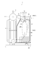
- FIG. 2 is a vertical sectional view schematically showing the configuration of the marine boiler according to the embodiment.
- FIG. 3 is a perspective view schematically showing a marine boiler according to one embodiment.
- a marine boiler 1 is provided with a furnace 2, a burner device 10 that is provided in a furnace wall portion 3 of the furnace 2, and injects combustion fuel and combustion air into the furnace 2.
- At least one volatile gas that is provided in the furnace wall portion 3 of the furnace 2 away from the burner device 10 and that supplies a volatile gas 65 (VOC gas) containing a volatile organic compound and an inert gas into the furnace 2.
- VOC gas volatile gas 65
- the marine boiler 1 includes an evaporation tube group 4 arranged in the furnace 2, a water drum 5 provided below the evaporation tube group 4, a steam drum 6 provided above the evaporation tube group 4, Equipped with.
- the marine boiler 1 according to at least one embodiment of the present disclosure is assumed to be an auxiliary boiler that generates steam serving as a drive source of a cargo oil pump 36 (see FIG. 1) used as power for cargo handling work of a marine vessel. ..
- the steam generated in the auxiliary boiler is supplied to the cargo handling turbine 35, and the rotational power of the cargo handling turbine 35 is accumulated as a drive source for the cargo oil pump 36.
- the furnace 2 is a hollow body for reacting and burning combustion fuel and combustion air, and can take various forms such as a cylindrical shape and a box shape.
- a furnace 2 includes a furnace wall portion 3 that partitions the outside and the inside.
- a combustion space 200 in which a combustion flame (flame 80) of combustion fuel, combustion air, and/or VOC gas injected from one end of the furnace 2 is formed, and combustion gas generated by combustion. It has become a flow path.
- the above-mentioned evaporation tube group 4 is arranged on the downstream side in the flow direction of the combustion gas, and the combustion gas outlet 8 continuing to the chimney 37 is provided on the upper side of the furnace 2 on the further downstream side.
- a steam outlet 9 is provided above the steam drum 6.
- the furnace wall portion 3 of the furnace 2 is configured to include a plurality of furnace wall tubes through which boiler water can pass.
- the furnace wall portion 3 includes a side surface portion 3C formed by arranging a plurality of furnace wall tubes along a vertical direction (for example, a vertical direction of the paper surface in FIG. 2) in a plane shape, and an upper and lower portions of the furnace wall tubes.
- Each includes a ceiling portion 3A and a bottom portion 3B that are arranged so as to face each other by being bent.
- the ceiling portion 3A and the bottom portion 3B may be inclined with respect to the horizontal direction so as to form an obtuse angle with the side surface portion 3C, for example.
- the burner device 10 injects a mixed gas of a combustion fuel (including a gas fuel or a liquid fuel, for example), which is a main fuel, and a carrier gas, and/or combustion air into the furnace 2.
- a combustion fuel including a gas fuel or a liquid fuel, for example
- the burner device 10 is disposed on the ceiling portion 3A of the furnace 2 and injects combustion fuel and combustion air downward. It may be configured to form a flame 80.
- the volatile gas supply unit 60 supplies the volatile gas 65 containing the VOC and the inert gas, which are conveyed through the VOC gas line 34, into the furnace 2.
- the volatile gas supply part 60 may be arranged, for example, in the ceiling part 3A or in the side part 3C (upper part thereof) of the furnace wall part 3.
- the volatile gas supply unit 60 supplies the volatile gas 65 supplied from the volatile gas supply unit 60 into the furnace 2 to the downstream side portion of the flame 80, for example, as illustrated in FIG. It is provided in a position and an orientation where it can be mixed.
- the volatile gas supply unit 60 may be a port opened toward the inside of the furnace 2 or a nozzle capable of injecting the volatile gas 65 into the furnace 2. Further, the volatile gas supply unit 60 mixes the volatile gas 65 with the flame 80 in the combustion region on the downstream side of the flame holding region 90 without supplying the volatile gas 65 to the flame holding region 90 described later. May be configured to do so.
- the volatile gas supply unit 60 is arranged as a separate body from the burner device 10 at a position separated from the burner device 10 in the furnace wall portion 3 of the furnace 2, so that volatilization containing an inert gas is performed.
- the property gas 65 can be supplied into the furnace 2 at a position remote from the burner device 10. Therefore, the volatile gas 65 containing the inert gas can be treated in the furnace 2 while suppressing the deterioration of the combustibility of the fuel by the burner device 10.
- the volatile gas supply part 60 is provided at a position separated from the burner device 10, for example, the burner device 10 and the volatilization device 10 are volatilized as compared with the conventional marine boiler in which the volatile gas supply part 60 is integrally provided with the burner device 10. There is a high degree of freedom in the arrangement of the characteristic gas supply unit 60, and there is no restriction on the VOC amount.
- FIG. 4A is a diagram showing a burner device according to one embodiment, and is a cross-sectional view showing the overall configuration of the burner device.
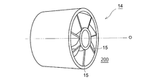
- FIG. 4B is a diagram illustrating the burner device according to the embodiment, and is a perspective view of the swirler according to the embodiment.
- the burner device 10 includes a fuel injection unit 11 for injecting combustion fuel into the furnace 2 and a combustion air into the furnace 2.
- the air injection part 12 for injecting, and the cylindrical body 13 which accommodates the fuel injection part 11 and the air injection part 12 may be included.
- the volatile gas supply unit 60 may be provided separately from the outer peripheral surface 13A of the tubular body 13.
- the fuel injection unit 11 may include a burner having a nozzle that injects liquid fuel or gas fuel, for example.
- the fuel injection unit 11 includes an inner cylinder 11A and an outer cylinder 11B arranged so as to surround a part of the inner cylinder 11A.
- the fuel injection part 11 may be arrange
- a fuel supply path 11C is formed on the inner peripheral side of the inner cylinder 11A.
- the fuel supplied to the fuel supply passage 11C is a liquid fuel such as C heavy oil.
- One end of the inner cylinder 11A faces the combustion space 200 in the furnace 2.
- the outer cylinder 11B is arranged on the combustion space 200 side of the primary air supply passage 12C and divides the primary air supply passage 12C into an inner peripheral side passage and an outer peripheral side passage. Of the primary air that passes through the primary air supply passage 12C, the primary air that has flowed into the outer peripheral side flow path is blown out into the combustion space 200 as it is.
- the fuel injection unit 11 may be configured to blow the primary air, which has flowed into the inner circumferential side passage, into the combustion space 200 by applying a swirling force by the swirler 14 described later.
- the air injecting section 12 is, for example, a combustion air in the furnace 2 via an air sleeve formed between the inner peripheral surface 13B of the tubular body 13 and the fuel injecting section 11 arranged in the tubular body 13. May be configured to be injected.
- the air injection unit 12 includes a primary air nozzle 12A provided on the outer peripheral side of the outer cylinder 11B of the fuel injection unit 11 and a secondary air nozzle 12B provided further on the outer peripheral side of the primary air nozzle 12A. May be.
- a primary air supply path 12C for supplying primary air for combustion is provided between the inner peripheral surface of the primary air nozzle 12A and the outer peripheral surface of the inner cylinder 11A, and the inner peripheral surface of the secondary air nozzle 12B and the primary air supply path 12C are provided.
- a secondary air supply path 12D to which secondary air for combustion is supplied is provided between the outer peripheral surface of the air nozzle 12A and the secondary surface.
- a primary vane 17 and a secondary vane 18 may be provided on the air supply sides of the primary air supply passage 12C and the secondary air supply passage 12D, respectively. The amount of air supplied to each air supply passage is adjusted by these vanes 17, 18.
- the tubular body 13 can define the outer edge of the burner device 10 in the radial direction, and for example, the secondary air nozzle 12B arranged at the outermost radial direction in the air injection unit 12 may be applied.
- the tubular body 13 may include a diameter-increased portion 13C (large-diameter portion) whose diameter is increased toward the downstream side in the injection direction of the combustion fuel and the combustion air.
- the outer circumference of the large diameter portion of the tubular body 13 may be applied as the outer peripheral surface 13A of the tubular body 13.
- the region inside the expanded diameter portion 13C of the tubular body 13 is defined as a flame holding region 90 for igniting and/or holding the flame 80.
- the position of the flame holding region 90 in the furnace 2 may relatively change depending on, for example, the amount of fuel injected by the burner device 10 per unit time, the type of fuel, and the like. Therefore, for example, the upstream side portion of the flame 80 in the fuel injection direction (that is, the upper side portion of the flame 80 in the case of the downward flame 80) may be defined as the flame holding region 90.
- the combustion fuel and The burner device 10 for supplying the combustion air and the volatile gas supply part 60 for supplying the volatile gas containing the inert gas are separately configured, and are physically separated from each other. can do. Therefore, it is possible to effectively prevent the volatile gas 65 containing the inert gas from being mixed into the flame 80 in the flame holding region 90 of the burner device 10.
- the burner device 10 includes a swirler 14 for imparting a swirl force to the combustion air injected into the furnace 2.
- the volatile gas supply unit 60 may be configured to supply the volatile gas 65 along the swirling direction of the swirling flame (flame 80) by the burner device 10.
- the swirler 14 is provided in the inner peripheral side flow passage of the primary air supply passage 12C, and swirls the primary air mainly for the purpose of flame holding.
- the swirler 14 extends from the air supply side of the primary air supply passage 12C (inner peripheral side passage) toward the combustion space 200 side.
- the swirler 14 may be provided near the end of the primary air supply passage 12C on the combustion space 200 side.
- the swirler 14 has a plurality of blades 15 radially provided between the inner cylinder 11A and the outer cylinder 11B. Note that FIG. 4B illustrates the case where seven blades 15 are provided.
- the plurality of blades 15 are inclined in the same direction with respect to the axis O of the tubular body 13 and are arranged apart from each other in the circumferential direction of the burner.
- the volatile gas 65 supplied from the volatile gas supply unit 60 does not impede the flow of the swirling flame by the burner device 10 and the flame 80 follows the flow direction of the swirling flame. It may be configured to be mixed in.
- the combustion air is supplied as a swirl flow into the furnace 2 and the volatile gas 65 is supplied along the swirl direction of the swirl flame formed thereby, so that the volatile gas containing the inert gas is generated.
- the gas 65 can be efficiently mixed into the swirling flame. Therefore, the volatile gas 65 that has been supplied into the furnace 2 but is not mixed into the flame 80 and is discharged untreated can be significantly suppressed.
- the volatile gas supply unit 60 is volatile along a direction (or an inclined direction) intersecting the injection direction of the combustion fuel injected from the fuel injection unit 11 of the burner device 10. It may be configured to inject the gas 65. That is, the volatile gas supply unit 60 is configured to supply the volatile gas 65 toward a direction toward the flame 80 of the combustion fuel injected from the fuel injection unit 11 instead of away from the flame 80. In this case, the volatile gas supply unit 60 may be configured to supply the volatile gas 65 in a direction that intersects the injection direction of the combustion fuel in the forward direction.
- the combustibility of the fuel injected from the burner device 10 is increased. It is possible to efficiently mix the volatile gas 65 into the flame 80 formed by the burner device 10 while suppressing the decrease in the temperature. Therefore, the volatile gas 65 that has been supplied into the furnace 2 but is not mixed into the flame 80 and is discharged untreated can be significantly suppressed.
- the volatile gas supply unit 60 may be arranged on the same surface of the furnace wall 3 as the surface on which the burner device 10 is arranged. ..
- both the burner device 10 and the volatile gas supply unit 60 may be disposed on the ceiling portion 3A of the furnace wall portion 3, the side surface portion 3C, or the bottom portion 3B. May be.
- the volatile gas supply unit 60 As described above, by disposing the volatile gas supply unit 60 on the same surface of the furnace wall 3 as the surface on which the burner device 10 is arranged, the volatile gas containing the above-mentioned inert gas supplied into the furnace 2. Since the injection direction of the volatile gas 65 can be made to follow the injection direction of the combustion fuel while suppressing the supply of 65 to the flame holding area 90, the above-mentioned inert gas is provided on the downstream side of the flame holding area 90. It is possible to efficiently mix the volatile gas 65 containing P into the flame 80 along the flow of the flame 80 to render it harmless.
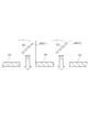
- FIG. 5 is a cross-sectional view showing the volatile gas supply unit in the embodiment.
- the marine boiler 1 may include a plurality of volatile gas supply units 60, as illustrated in FIGS. 3 and 5, for example.
- each of the plurality of volatile gas supply units 60 may include a valve 62 for adjusting the flow rate of the volatile gas 65 supplied into the furnace 2.
- the plurality of volatile gas supply units 60 may be arranged at intervals (for example, at equal intervals) along one side of the furnace wall portion 3 to which the burner device 10 is attached, for example.
- the plurality of volatile gas supply units 60 may be arranged along different sides of the furnace wall 3 to which the burner device 10 is attached.
- the opening degree of the valve 62 provided in each volatile gas supply unit 60 may be managed independently.
- the flow rate of the volatile gas 65 supplied from each volatile gas supply unit 60 may be different or the same.
- the volatile gas 65 can be supplied into the furnace 2 through the plurality of volatile gas supply units 60.
- the volatile gas 65 can be mixed into the flame 80 in the furnace 2 from a plurality of directions. Therefore, the volatile gas 65 can be efficiently processed in the furnace 2.
- the flow rate of the volatile gas 65 supplied from each volatile gas supply unit 60 into the furnace 2 can be arbitrarily adjusted by the valve 62. Therefore, an appropriate amount of volatile gas 65 that can be processed by the flame 80 can be supplied into the furnace 2 depending on the size and combustion state of the flame 80 formed in the furnace 2 by the burner device 10.
- the marine boiler 1 capable of efficiently processing the volatile gas 65 in the furnace 2 while suppressing the unreacted volatile gas 65 from being discharged from the furnace 2.
- the plurality of volatile gas supply units 60 may be arranged in an arc shape with the burner device 10 as the center.
- FIG. 6 is a block diagram showing the configuration of the control system in the embodiment.
- the marine boiler 1 has an exhaust gas sensor 70 for detecting the concentration of the volatile gas 65 in the exhaust gas discharged from the furnace 2, and an opening degree of a valve 62.
- a controller 50 as a control unit that drives the valve actuator 63 based on the detection signal of the exhaust gas sensor 70 to adjust the opening degree of the valve 62.
- the exhaust gas sensor 70 may be disposed near the combustion gas outlet 8 (downstream side or upstream side) in the flow path of the combustion gas (exhaust gas).
- the valve actuator 63 is configured to change and maintain the opening degree of the valve 62 to be fully opened, fully closed, or an arbitrary opening between these, based on a control signal from the controller 50.
- the controller 50 is, for example, a computer, and includes a CPU 51, a ROM (Read Only Memory) 53 as a storage unit for storing various programs executed by the CPU 51, and a RAM (Random memory) functioning as a work area when each program is executed.
- a hard disk drive (HDD) as a mass storage device (not shown)
- a communication interface for connecting to a communication network, an access unit to which an external storage device is mounted, reference data, etc. are stored.
- Database 57 and the like are connected via a bus 54.
- the controller 50 may be connected to, for example, an input unit (not shown) such as a keyboard and a mouse, a display unit (not shown) such as a liquid crystal display device for displaying data, and the like.
- the ROM 53 may store a VOC gas flow rate adjustment program 55 for adjusting the flow rate of the volatile gas 65.
- the CPU 51 reads out the VOC gas flow rate adjustment program 55 from the ROM 53, expands it in the RAM 52, and executes it to perform control for adjusting the opening degree of the valve 62 based on the detection signal of the exhaust gas sensor 70. The flow rate of the volatile gas 65 supplied from the gas supply unit 60 into the furnace 2 is adjusted.
- the controller 50 drives the valve actuator 63 based on the detection signal of the exhaust gas sensor 70 to change the opening degree of the valve 62. Since it can be automatically adjusted, an appropriate amount of volatile gas 65 that can be burned by the flame 80 in the furnace 2 in real time is burned in the furnace 2 in accordance with the size and the combustion state of the flame 80 in the furnace 2 by the burner device 10. Can be supplied.
- FIG. 7 is a flowchart showing a method for modifying a marine boiler according to one embodiment.
- a method for modifying a marine boiler according to at least one embodiment of the present invention is a method for modifying a marine boiler 1 in which a burner device 10 is arranged on a furnace wall portion 3 of a furnace 2, and A step of specifying the installation position of the volatile gas supply unit 60 at a position separated from the burner device 10 on the wall section 3 (Step S10), and a step of providing the volatile gas supply unit 60 at the specified installation position (Step S20). And are equipped with.
- step S10 when the position separated from the burner device 10 in the furnace wall portion 3 is specified, the volatile gas supply portion 60 is installed in consideration of the arrangement of the volatile gas supply portion 60 in some of the above-described embodiments.
- the position may be specified.
- step S20 the volatile gas supply unit 60 separate from the burner device 10 is installed at the installation position thus identified.
- the attachment opening for the volatile gas supply unit 60 may be formed by bending the furnace wall tube of the furnace wall 3 corresponding to the position specified in step S10. Good.
- the volatile gas supply part 60 is provided at a position separated from the burner device 10, for example, compared to the conventional case where the volatile gas supply part 60 is integrally provided with the burner device 10.
- the degree of freedom in the arrangement of the device 10 and the volatile gas supply unit 60 is high, and the VOC amount is not restricted.
- the marine boiler 1 can be modified by additionally providing the volatile gas supply unit 60 that is separate from the burner device 10, the burner device 10 that has been conventionally used can be used. Therefore, the marine boiler 1 capable of treating the volatile gas 65 in the furnace 2 can be provided at low cost while suppressing the risk of misfire.
- the volatile gas 65 containing an inert gas can be treated in the furnace 2 while suppressing deterioration of the combustibility of fuel.
- the marine boiler 1 is described as an auxiliary boiler, but the marine boiler 1 in other embodiments includes, for example, an unillustrated superheater and is used as power for propelling the marine vessel. It may be a main boiler that generates steam or a boiler that is used for other purposes such as for power generation.
Landscapes
- Engineering & Computer Science (AREA)
- Mechanical Engineering (AREA)
- Chemical & Material Sciences (AREA)
- Combustion & Propulsion (AREA)
- General Engineering & Computer Science (AREA)
- Environmental & Geological Engineering (AREA)
- Physics & Mathematics (AREA)
- Thermal Sciences (AREA)
- Ocean & Marine Engineering (AREA)
- Incineration Of Waste (AREA)
- Combustion Of Fluid Fuel (AREA)
Abstract
舶用ボイラは、火炉と、前記火炉の炉壁部に設けられ、燃焼用燃料及び燃焼用空気を前記火炉内に噴射するバーナ装置と、前記火炉の前記炉壁部に前記バーナ装置から離間して設けられ、揮発性有機化合物と不活性ガスとを含む揮発性ガスを前記火炉内に供給する少なくとも一つの揮発性ガス供給部と、を備えている。
Description
本開示は舶用ボイラ及び舶用ボイラの改造方法に関する。
従来、タンカー等の船舶、浮体式生産貯蔵積出設備(floating production,storage and offloading:FPSO)、又は浮体式貯蔵積出設備(floating storage and offloading unit:FSO)に搭載される原油タンクにおいては、揮発性有機化合物(volatile organic compounds)を含むガス(以下、VOCガス又は揮発性ガスという。)が発生することが知られている。そして、近年では、原油タンク内で生じるVOCガスを大気に放出せずに無害化することが望まれている。例えば、特許文献1には、上記のようなVOCガスを火炉内に供給するように構成された舶用ボイラが開示されている。
ところで、原油タンク内の空間には不活性ガス(イナートガス)が封入されるため、上記VOCガスは不活性ガスを含むことがある。不活性ガスを含むVOCガスは主燃料である燃焼用燃料に比べて低カロリーであり燃焼性が低い。このため、不活性ガスを含むVOCガスを火炉内におけるバーナ装置の噴出口近傍に供給すると、バーナ装置における主燃料の燃焼性の低下を招いて失火する恐れがある。この点、特許文献1には、燃料の燃焼性を低下させることなく不活性ガスを含むVOCガスを火炉内で処理することに関する知見は開示されていない。
上述の事情に鑑みて、本発明の少なくとも一実施形態は、燃料の燃焼性の低下を抑制しつつ不活性ガスを含む揮発性ガスを火炉内で処理することを目的とする。
(1)本発明の少なくとも一実施形態に係る舶用ボイラは、
火炉と、
前記火炉の炉壁部に設けられ、燃焼用燃料及び燃焼用空気を前記火炉内に噴射するバーナ装置と、
前記火炉の前記炉壁部に前記バーナ装置から離間して設けられ、揮発性有機化合物と不活性ガスとを含む揮発性ガスを前記火炉内に供給する少なくとも一つの揮発性ガス供給部と、
を備える。
火炉と、
前記火炉の炉壁部に設けられ、燃焼用燃料及び燃焼用空気を前記火炉内に噴射するバーナ装置と、
前記火炉の前記炉壁部に前記バーナ装置から離間して設けられ、揮発性有機化合物と不活性ガスとを含む揮発性ガスを前記火炉内に供給する少なくとも一つの揮発性ガス供給部と、
を備える。
上記(1)の構成によれば、火炉の炉壁部のうち、バーナ装置から離間した位置にバーナ装置とは別体として揮発性ガス供給部が配置されるから、不活性ガスを含む揮発性ガスを、バーナ装置から離れた位置において火炉内に供給することができる。よって、バーナ装置における燃焼用燃料の燃焼性の低下を抑制しつつ不活性ガスを含む揮発性ガスを火炉内で処理することができる。また、バーナ装置と離間した位置に揮発性ガス供給部を設けるから、例えば揮発性ガス供給部をバーナ装置と一体的に設けていた従来の舶用ボイラに比べてバーナ装置及び揮発性ガス供給部の配置の自由度が高い。よって、VOC量の制約を受けることなく装置のレイアウトを決定することができる。
(2)幾つかの実施形態では、上記(1)の構成において、
前記バーナ装置は、
前記火炉内に前記燃焼用燃料を噴射するための燃料噴射部と、
前記火炉内に前記燃焼用空気を噴射するための空気噴射部と、
前記燃料噴射部及び前記空気噴射部を収納する筒状体と、を含み、
前記揮発性ガス供給部は、
前記筒状体の外周面から離間して設けられていてもよい。
前記バーナ装置は、
前記火炉内に前記燃焼用燃料を噴射するための燃料噴射部と、
前記火炉内に前記燃焼用空気を噴射するための空気噴射部と、
前記燃料噴射部及び前記空気噴射部を収納する筒状体と、を含み、
前記揮発性ガス供給部は、
前記筒状体の外周面から離間して設けられていてもよい。
上記(2)の構成によれば、バーナ装置の燃料噴射部及び空気噴射部を収納する筒状体の外周面から離間して揮発性ガス供給部が配置されるから、燃焼用燃料及び燃焼用空気を噴射するためのバーナ装置と、不活性ガスを含む揮発性ガスを供給するための揮発性ガス供給部とをそれぞれ別体として構成し、互いを物理的に離隔して配置することができる。よって、不活性ガスを含む揮発性ガスがバーナ装置における燃料噴射部の直近で火炎に混入することを効果的に抑制することができる。
(3)幾つかの実施形態では、上記(2)の構成において、
前記揮発性ガス供給部は、前記燃料噴射部から噴射される前記燃焼用燃料の噴射方向に対して交差する方向に沿って、前記揮発性ガスを供給するように構成されてもよい。
前記揮発性ガス供給部は、前記燃料噴射部から噴射される前記燃焼用燃料の噴射方向に対して交差する方向に沿って、前記揮発性ガスを供給するように構成されてもよい。
上記(3)の構成によれば、燃料噴射部から噴射される燃焼用燃料の噴射方向に対して交差する方向に沿って揮発性ガスが供給されるから、バーナ装置における燃焼用燃料の燃焼性の低下を抑制しつつ、バーナ装置により形成される火炎に対して揮発性ガスを効率的に混入することができる。したがって、火炉内に供給されたにも関わらず火炎に混入されずに未処理のまま排出される揮発性ガスを大幅に抑制することができる。
(4)幾つかの実施形態では、上記(1)~(3)のいずれか一つの構成において、
前記揮発性ガス供給部は、前記炉壁部のうち前記バーナ装置が配置される一面と同一面に配置されていてもよい。
前記揮発性ガス供給部は、前記炉壁部のうち前記バーナ装置が配置される一面と同一面に配置されていてもよい。
上記(4)の構成によれば、炉壁部のうちバーナ装置が配置された一面と同一面に揮発性ガス供給部を配置することにより、火炉内に供給された上記不活性ガスを含む揮発性ガスがバーナ装置の直近で火炎に混入することを効果的に抑制しつつ、揮発性ガスの供給方向を燃焼用燃焼の噴射方向に沿わせることができるから、バーナ装置の下流側で上記不活性ガスを含む揮発性ガスを火炎に効率よく混入することができる。
(5)幾つかの実施形態では、上記(1)~(4)の何れか一つの構成において、
前記バーナ装置は、前記火炉内に噴射される前記燃焼用空気に対して旋回力を付与するためのスワラを含み、
前記揮発性ガス供給部は、前記バーナ装置による旋回火炎の旋回方向に沿って前記揮発性ガスを供給するように構成されてもよい。
前記バーナ装置は、前記火炉内に噴射される前記燃焼用空気に対して旋回力を付与するためのスワラを含み、
前記揮発性ガス供給部は、前記バーナ装置による旋回火炎の旋回方向に沿って前記揮発性ガスを供給するように構成されてもよい。
上記(5)の構成によれば、スワラにより燃焼用空気が旋回流として火炉内に供給され、これによって形成される旋回火炎の旋回方向に沿って不活性ガスを含む揮発性ガスが供給されるから、揮発性ガスを旋回火炎に効率よく混入することができる。したがって、火炉内に供給されたにも関わらず火炎に混入されずに未処理のまま排出される揮発性ガスを大幅に抑制することができる。
(6)幾つかの実施形態では、上記(1)~(5)の何れか一つの構成において、
前記少なくとも一つの揮発性ガス供給部は、複数の揮発性ガス供給部を含み、
前記複数の揮発性ガス供給部の各々は、前記火炉内に供給する前記揮発性ガスの流量を調節するためのバルブを含んでいてもよい。
前記少なくとも一つの揮発性ガス供給部は、複数の揮発性ガス供給部を含み、
前記複数の揮発性ガス供給部の各々は、前記火炉内に供給する前記揮発性ガスの流量を調節するためのバルブを含んでいてもよい。
上記(6)の構成によれば、複数の揮発性ガス供給部を介して火炉内に揮発性ガスを供給することができるから、例えば火炉内の火炎に対して複数の方向から揮発性ガスを混入することができる。その際、各々の揮発性ガス供給部から火炉内に供給する揮発性ガスの流量をバルブによって任意に調節することができる。よって、バーナ装置によって火炉内に形成される火炎の大きさや燃焼状況に応じて、当該火炎によって処理できる適量の揮発性ガスを火炉内に供給することができる。これにより、未反応の揮発性ガスが火炉から排出されることを抑制しつつ、該火炉内で揮発性ガスを効率よく処理可能な舶用ボイラを提供することができる。
(7)幾つかの実施形態では、上記(6)の構成において、
舶用ボイラは、
前記火炉から排出される排ガス中に含まれる前記揮発性ガスの濃度を検出するための排ガスセンサと、
前記排ガスセンサの検出信号に基づき前記バルブの開度を調節するためのコントローラと、
を備えていてもよい。
舶用ボイラは、
前記火炉から排出される排ガス中に含まれる前記揮発性ガスの濃度を検出するための排ガスセンサと、
前記排ガスセンサの検出信号に基づき前記バルブの開度を調節するためのコントローラと、
を備えていてもよい。
上記(7)の構成によれば、コントローラにより、排ガスセンサの検出信号に基づいてバルブの開度を自動的に調節することができるから、バーナ装置による火炉内の火炎の大きさや燃焼状況に応じて、当該火炎によって処理できる適量の揮発性ガスをリアルタイムで火炉内に供給することができる。
(8)本発明の少なくとも一実施形態に係る舶用ボイラの改造方法は、
火炉の炉壁部にバーナ装置が配置された舶用ボイラの改造方法であって、
前記炉壁部において前記バーナ装置から離間した位置に揮発性ガス供給部の設置位置を特定するステップと、
特定された前記設置位置に揮発性ガス供給部を設けるステップと、を備える。
火炉の炉壁部にバーナ装置が配置された舶用ボイラの改造方法であって、
前記炉壁部において前記バーナ装置から離間した位置に揮発性ガス供給部の設置位置を特定するステップと、
特定された前記設置位置に揮発性ガス供給部を設けるステップと、を備える。
上記(8)の方法によれば、バーナ装置と離間した位置に揮発性ガス供給部を設けるから、例えば揮発性ガス供給部をバーナ装置と一体的に設けていた従来の舶用ボイラに比べてバーナ装置及び揮発性ガス供給部の配置の自由度が高く、VOC量の制約を受けることがない。また、バーナ装置と別体の揮発性ガス供給部を追加的に設けることで舶用ボイラを改造することができるから、従来使用していたバーナ装置を流用することができる。よって、失火の虞を抑制しつつ、火炉内で揮発性ガスを処理可能な舶用ボイラを低コストで提供することができる。
本発明の少なくとも一実施形態によれば、火炎の燃焼性の低下を抑制しつつ不活性ガスを含む揮発性ガスを火炉内で処理することができる。
以下、添付図面を参照して本発明の幾つかの実施形態について説明する。ただし、実施形態として記載されている又は図面に示されている構成部品の寸法、材質、形状、その相対的配置等は、本発明の範囲をこれに限定する趣旨ではなく、単なる説明例にすぎない。
例えば、「ある方向に」、「ある方向に沿って」、「平行」、「直交」、「中心」、「同心」或いは「同軸」等の相対的或いは絶対的な配置を表す表現は、厳密にそのような配置を表すのみならず、公差、若しくは、同じ機能が得られる程度の角度や距離をもって相対的に変位している状態も表すものとする。
また例えば、四角形状や円筒形状等の形状を表す表現は、幾何学的に厳密な意味での四角形状や円筒形状等の形状を表すのみならず、同じ効果が得られる範囲で、凹凸部や面取り部等を含む形状も表すものとする。
一方、一の構成要素を「備える」、「具える」、「具備する」、「含む」、又は、「有する」という表現は、他の構成要素の存在を除外する排他的な表現ではない。
例えば、「ある方向に」、「ある方向に沿って」、「平行」、「直交」、「中心」、「同心」或いは「同軸」等の相対的或いは絶対的な配置を表す表現は、厳密にそのような配置を表すのみならず、公差、若しくは、同じ機能が得られる程度の角度や距離をもって相対的に変位している状態も表すものとする。
また例えば、四角形状や円筒形状等の形状を表す表現は、幾何学的に厳密な意味での四角形状や円筒形状等の形状を表すのみならず、同じ効果が得られる範囲で、凹凸部や面取り部等を含む形状も表すものとする。
一方、一の構成要素を「備える」、「具える」、「具備する」、「含む」、又は、「有する」という表現は、他の構成要素の存在を除外する排他的な表現ではない。
図1は本発明の少なくとも一実施形態に係る舶用ボイラ1を備えたVOCガス処理システム100を示す概略構成図である。図1に例示するように、VOCガス処理システム100は、タンカー等の船舶やFPSO/FSO(浮体式石油・ガス生産/貯蔵設備)に設置される原油タンク22と、原油タンク22内から抜き出された気体からVOC(volatile organic compounds:揮発性有機化合物)を分離するVOC分離部27と、分離されたVOCを液化するVOC液化部29と、液化された液化VOCを貯留する液化VOCタンク32と、VOC分離部27で分離されず気体中に残ったVOCを主燃料と混焼する舶用ボイラ1と、を備えている。
原油タンク22は、原油が貯蔵されるタンクであり、この原油タンク22には、図示しない原油掘削設備や石油の生産設備又はこれらの貯蔵設備から輸送ライン25を介して原油が流入する。原油タンク22の内部には、原油から揮発したVOCの発火を防止するためのイナートガスが封入されている。イナートガスは、例えば、CO2やN2等の不活性ガスである。原油タンク22内の上方の空間(タンク内上部空間24)は、VOCとイナートガスとが混合したVOCガスによって満たされている。原油タンク22内のVOCガスは、VOCガスライン26を経由してVOC分離部27に導かれる。
VOC分離部27によって分離されて回収されたVOCは、VOC液化部29で液化され、液化VOCタンク32に貯留された後、原油タンク22に戻されるか、或いは舶用ボイラ1用の液体燃料として利用される。一方、VOC分離部27で大部分のVOCが取り除かれ、微量のVOCとイナートガスとを含む残りの気体(VOCガス)は、VOCガスライン34を経由して舶用ボイラ1に導かれる。
次に、本開示の少なくとも一実施形態に係る舶用ボイラ1の構成について説明する。
図2は一実施形態に係る舶用ボイラの構成を概略的に示す縦断面図である。図3は一実施形態に係る舶用ボイラを概略的に示す斜視図である。
図2及び図3に例示するように、舶用ボイラ1は、火炉2と、火炉2の炉壁部3に設けられ、燃焼用燃料及び燃焼用空気を火炉2内に噴射するバーナ装置10と、火炉2の炉壁部3にバーナ装置10から離間して設けられ、揮発性有機化合物と不活性ガスとを含む揮発性ガス65(VOCガス)を火炉2内に供給する少なくとも一つの揮発性ガス供給部60と、を備えている。また、舶用ボイラ1は、火炉2内に配置された蒸発管群4と、蒸発管群4の下方に設けられた水ドラム5と、蒸発管群4の上方に設けられた蒸気ドラム6と、を備えている。
なお、本開示の少なくとも一実施形態に係る舶用ボイラ1は、船舶の荷役作業の動力として用いられるカーゴオイルポンプ36(図1参照)の駆動源となる蒸気を発生させる補助ボイラであるものとする。補助ボイラで発生した蒸気は、荷役用タービン35に供給され、荷役用タービン35の回転動力がカーゴオイルポンプ36の駆動源として蓄積される。
図2は一実施形態に係る舶用ボイラの構成を概略的に示す縦断面図である。図3は一実施形態に係る舶用ボイラを概略的に示す斜視図である。
図2及び図3に例示するように、舶用ボイラ1は、火炉2と、火炉2の炉壁部3に設けられ、燃焼用燃料及び燃焼用空気を火炉2内に噴射するバーナ装置10と、火炉2の炉壁部3にバーナ装置10から離間して設けられ、揮発性有機化合物と不活性ガスとを含む揮発性ガス65(VOCガス)を火炉2内に供給する少なくとも一つの揮発性ガス供給部60と、を備えている。また、舶用ボイラ1は、火炉2内に配置された蒸発管群4と、蒸発管群4の下方に設けられた水ドラム5と、蒸発管群4の上方に設けられた蒸気ドラム6と、を備えている。
なお、本開示の少なくとも一実施形態に係る舶用ボイラ1は、船舶の荷役作業の動力として用いられるカーゴオイルポンプ36(図1参照)の駆動源となる蒸気を発生させる補助ボイラであるものとする。補助ボイラで発生した蒸気は、荷役用タービン35に供給され、荷役用タービン35の回転動力がカーゴオイルポンプ36の駆動源として蓄積される。
火炉2は、燃焼用燃料と燃焼用空気とを反応させて燃焼させるための中空体であり、例えば、円筒形状や箱型等、種々の形態をとり得る。このような火炉2は、外部と内部とを区画する炉壁部3を含む。火炉2の内部は、該火炉2の一端から噴射された燃焼用燃料、燃焼用空気、及び/又はVOCガスの燃焼火炎(火炎80)が形成される燃焼空間200、並びに燃焼によって生じた燃焼ガスの流路となっている。燃焼ガスの流れ方向の下流側には上述した蒸発管群4が配置され、さらに下流側である火炉2の上部には煙突37に続く燃焼ガス出口8が設けられる。なお、蒸気ドラム6の上部には蒸気出口9が設けられている。
火炉2の炉壁部3は、ボイラ水が通過可能な複数の炉壁管を含んで構成される。具体的に、炉壁部3は、例えば鉛直方向(例えば図2における紙面上下方向)に沿う複数の炉壁管が面状に配列されてなる側面部3Cと、炉壁管の上部及び下部がそれぞれ曲成されることで互いに対向するように配置された天井部3A及び底部3Bとを含む。天井部3A及び底部3Bは、それぞれ水平方向に対して例えば側面部3Cと鈍角をなすように傾斜していてもよい。
バーナ装置10は、火炉2内に主燃料である燃焼用燃料(例えば気体燃料又は液体燃料を含む)と搬送用ガスとの混合気体、及び/又は燃焼用空気を噴射する。幾つかの実施形態では、例えば図2及び図3に示すように、バーナ装置10は、火炉2の天井部3Aに配置され、燃焼用燃料と燃焼用空気とを下方に向けて噴射することで火炎80を形成するように構成されていてもよい。
揮発性ガス供給部60は、VOCガスライン34を通って搬送されたVOCと不活性ガスとを含む揮発性ガス65を火炉2内に供給する。この揮発性ガス供給部60は、炉壁部3のうち、例えば天井部3Aに配置されていてもよいし、側面部3C(の上側部分)に配置されていてもよい。いずれの場合も、揮発性ガス供給部60は、例えば、図2に例示するように、当該揮発性ガス供給部60から火炉2内に供給する揮発性ガス65を、火炎80の下流側部分に混入し得る位置及び向きで設けられる。
なお、揮発性ガス供給部60は、火炉2内に向けて開口されたポートであってもよいし、火炉2内に揮発性ガス65を噴射可能なノズルであってもよい。また、揮発性ガス供給部60は、後述する火炎保持領域90には揮発性ガス65を供給することなく該火炎保持領域90よりも下流側の燃焼領域において、火炎80に揮発性ガス65を混入するように構成されていてもよい。
なお、揮発性ガス供給部60は、火炉2内に向けて開口されたポートであってもよいし、火炉2内に揮発性ガス65を噴射可能なノズルであってもよい。また、揮発性ガス供給部60は、後述する火炎保持領域90には揮発性ガス65を供給することなく該火炎保持領域90よりも下流側の燃焼領域において、火炎80に揮発性ガス65を混入するように構成されていてもよい。
かかる構成によれば、火炉2の炉壁部3のうち、バーナ装置10から離間した位置にバーナ装置10とは別体として揮発性ガス供給部60が配置されるから、不活性ガスを含む揮発性ガス65を、バーナ装置10から離れた位置で火炉2内に供給することができる。よって、バーナ装置10による燃料の燃焼性の低下を抑制しつつ、不活性ガスを含む揮発性ガス65を火炉2内で処理することができる。また、バーナ装置10と離間した位置に揮発性ガス供給部60を設けるから、例えば揮発性ガス供給部60をバーナ装置10と一体的に設けていた従来の舶用ボイラに比べてバーナ装置10及び揮発性ガス供給部60の配置の自由度が高く、また、VOC量の制約を受けることがない。
図4Aは、一実施形態におけるバーナ装置を示す図であり、バーナ装置の全体構成を示す断面図である。図4Bは、一実施形態におけるバーナ装置を示す図であり、一実施形態におけるスワラの斜視図である。
幾つかの実施形態では、例えば図2及び図4Aに例示するように、バーナ装置10は、火炉2内に燃焼用燃料を噴射するための燃料噴射部11と、火炉2内に燃焼用空気を噴射するための空気噴射部12と、燃料噴射部11及び空気噴射部12を収納する筒状体13と、を含んでいてもよい。そして、揮発性ガス供給部60は、筒状体13の外周面13Aから離間して設けられていてもよい。
幾つかの実施形態では、例えば図2及び図4Aに例示するように、バーナ装置10は、火炉2内に燃焼用燃料を噴射するための燃料噴射部11と、火炉2内に燃焼用空気を噴射するための空気噴射部12と、燃料噴射部11及び空気噴射部12を収納する筒状体13と、を含んでいてもよい。そして、揮発性ガス供給部60は、筒状体13の外周面13Aから離間して設けられていてもよい。
燃料噴射部11は、例えば液体燃料や気体燃料を噴射するノズルを有するバーナを含んでいてもよい。この燃料噴射部11は、内筒11Aと、内筒11Aの一部を囲むように配置される外筒11Bとを備えている。なお、燃料噴射部11は、例えば筒状体13の軸線Oに沿って該筒状体13の径方向における中心部に配置されていてもよい。
内筒11Aの内周側には燃料供給路11Cが形成されている。燃料供給路11Cに供給される燃料は、例えばC重油等の液体燃料である。内筒11Aの一方の端部は火炉2内の燃焼空間200に面している。
外筒11Bは、一次空気供給路12Cの燃焼空間200側に配置され、一次空気供給路12Cを内周側流路と外周側流路とに仕切っている。一次空気供給路12Cを通る一次空気のうち外周側流路に流入した一次空気はそのまま燃焼空間200に吹き出す。一方、燃料噴射部11は、内周側流路に流入した一次空気を、後述するスワラ14によって旋回力を付与して燃焼空間200に吹き出すように構成されていてもよい。
空気噴射部12は、例えば筒状体13の内周面13Bと該筒状体13内に配置された燃料噴射部11との間に形成されるエアスリーブを介して火炉2内に燃焼用空気を噴射するように構成されてもよい。例えば空気噴射部12は、上記燃料噴射部11の外筒11Bの外周側に設けられた一次空気ノズル12Aと、一次空気ノズル12Aのさらに外周側に設けられた二次空気ノズル12Bとを備えていてもよい。一次空気ノズル12Aの内周面と内筒11Aの外周面との間には、燃焼用の一次空気が供給される一次空気供給路12Cが設けられ、二次空気ノズル12Bの内周面と一次空気ノズル12Aの外周面との間には、燃焼用の二次空気が供給される二次空気供給路12Dが設けられる。一次空気供給路12C、二次空気供給路12Dの空気供給側には、それぞれ、一次ベーン17及び二次ベーン18が設けられ得る。そして各空気供給路への空気供給量はこれらのベーン17,18によって調整される。
筒状体13は、バーナ装置10の径方向の外縁を規定し得るものであり、例えば上記空気噴射部12において径方向の最も外側に配置される二次空気ノズル12Bを適用してもよい。なお、筒状体13は、燃焼用燃料及び燃焼用空気の噴射方向の下流側に向けて拡径された拡径部13C(大径部)を含んでもよい。この場合、筒状体13の外周面13Aとして筒状体13の大径部の外周を適用してもよい。
幾つかの実施形態では、例えば図4Aに示すように、筒状体13の拡径部13Cの内側の領域を、火炎80の着火及び/又は保炎のための火炎保持領域90として規定してもよい。なお、火炉2内における火炎保持領域90の位置は、例えば、バーナ装置10による単位時間あたりの燃料の噴射量や燃料の種類等に応じて相対的に変化し得る。したがって、例えば燃料の噴射方向における火炎80の上流側部分(すなわち、下向きの火炎80の場合は当該火炎80の上側部分)を火炎保持領域90として規定してもよい。
このように、バーナ装置10の燃料噴射部11及び空気噴射部12を収納する筒状体13の外周面13Aから離間して揮発性ガス供給部60を配置した構成によれば、燃焼用燃料及び燃焼用空気を供給するためのバーナ装置10と、不活性ガスを含む揮発性ガスを供給するための揮発性ガス供給部60とをそれぞれ別体として構成し、互いを物理的に離隔して配置することができる。よって、不活性ガスを含む揮発性ガス65がバーナ装置10の火炎保持領域90において火炎80に混入することを効果的に抑制することができる。
幾つかの実施形態では、例えば図3及び図4A及び図4Bに例示するように、バーナ装置10は、火炉2内に噴射される燃焼用空気に対して旋回力を付与するためのスワラ14を含み、揮発性ガス供給部60は、バーナ装置10による旋回火炎(火炎80)の旋回方向に沿って揮発性ガス65を供給するように構成されてもよい。
スワラ14は、一次空気供給路12Cの内周側流路に設けられ、主に保炎を目的として一次空気を旋回させる。スワラ14は、一次空気供給路12C(内周側流路)の空気供給側から燃焼空間200側に向けて延在している。スワラ14は一次空気供給路12Cの燃焼空間200側の端部近傍に設けられてもよい。図4Bに示すように、スワラ14は、内筒11Aと外筒11Bとの間に放射状に複数設けられた羽根15を有している。なお、図4Bには羽根15が7枚設けられている場合を例示している。一実施形態では、複数の羽根15は、筒状体13の軸線Oに対して同一方向に傾斜するとともに、バーナの周方向に互いに離間して配置されている。
揮発性ガス供給部60は、該揮発性ガス供給部60から供給される揮発性ガス65が、バーナ装置10による旋回火炎の流れを阻害することなく、該旋回火炎の流れ方向に沿って火炎80に混入されるように構成されてもよい。
この構成によれば、燃焼用空気が旋回流として火炉2内に供給され、これによって形成される旋回火炎の旋回方向に沿って揮発性ガス65が供給されるから、不活性ガスを含む揮発性ガス65を旋回火炎に効率よく混入することができる。したがって、火炉2内に供給されたにも関わらず火炎80に混入されずに未処理のまま排出される揮発性ガス65を大幅に抑制することができる。
幾つかの実施形態において、揮発性ガス供給部60は、バーナ装置10の燃料噴射部11から噴射される燃焼用燃料の噴射方向に対して交差する方向(又は傾斜した方向)に沿って揮発性ガス65を噴射するように構成されていてもよい。つまり、揮発性ガス供給部60は、燃料噴射部11から噴射された燃焼用燃料による火炎80に対して離れる方向ではなく近づく方向に向けて揮発性ガス65を供給するように構成される。この場合、揮発性ガス供給部60は、燃焼用燃料の噴射方向に対して順方向に交差する方向に向けて揮発性ガス65を供給するように構成されていてもよい。
このように、燃料噴射部11から噴射される燃焼用燃料の噴射方向に対して交差する方向に沿って揮発性ガス65を供給する構成によれば、バーナ装置10から噴射された燃料の燃焼性の低下を抑制しつつ、バーナ装置10により形成される火炎80に対して揮発性ガス65を効率的に混入することができる。したがって、火炉2内に供給されたにも関わらず火炎80に混入されずに未処理のまま排出される揮発性ガス65を大幅に抑制することができる。
幾つかの実施形態では、図2及び図3に例示するように、揮発性ガス供給部60は、炉壁部3のうちバーナ装置10が配置される一面と同一面に配置されていてもよい。
例えば、バーナ装置10及び揮発性ガス供給部60はともに、炉壁部3の天井部3Aに配置されていてもよいし、側面部3Cに配置されていてもよいし、底部3Bに配置されていてもよい。
例えば、バーナ装置10及び揮発性ガス供給部60はともに、炉壁部3の天井部3Aに配置されていてもよいし、側面部3Cに配置されていてもよいし、底部3Bに配置されていてもよい。
このように、炉壁部3のうちバーナ装置10が配置された一面と同一面に揮発性ガス供給部60を配置することにより、火炉2内に供給された上記不活性ガスを含む揮発性ガス65が火炎保持領域90に供給されることを抑制しつつ、揮発性ガス65の噴射方向を燃焼用燃料の噴射方向に沿わせることができるから、火炎保持領域90の下流側で上記不活性ガスを含む揮発性ガス65を火炎80の流れに沿って該火炎80に効率よく混入し、無害化することができる。
図5は一実施形態における揮発性ガス供給部を示す断面図である。
幾つかの実施形態では、例えば図3及び図5に例示するように、舶用ボイラ1は、複数の揮発性ガス供給部60を備えてもよい。そして、複数の揮発性ガス供給部60の各々は、火炉2内に供給する揮発性ガス65の流量を調節するためのバルブ62を備えていてもよい。
複数の揮発性ガス供給部60は、例えばバーナ装置10が取り付けられた炉壁部3の一辺に沿って各々間隔を隔てて(例えば等間隔に)配置されていてもよい。或いは、複数の揮発性ガス供給部60は、バーナ装置10が取り付けられた炉壁部3の異なる辺に沿ってそれぞれ配置されていてもよい。
各々の揮発性ガス供給部60に設けられたバルブ62の開度はそれぞれ独立に管理してもよい。そして、各揮発性ガス供給部60から供給される揮発性ガス65の流量は各々異ならせてもよいし、同一としてもよい。
幾つかの実施形態では、例えば図3及び図5に例示するように、舶用ボイラ1は、複数の揮発性ガス供給部60を備えてもよい。そして、複数の揮発性ガス供給部60の各々は、火炉2内に供給する揮発性ガス65の流量を調節するためのバルブ62を備えていてもよい。
複数の揮発性ガス供給部60は、例えばバーナ装置10が取り付けられた炉壁部3の一辺に沿って各々間隔を隔てて(例えば等間隔に)配置されていてもよい。或いは、複数の揮発性ガス供給部60は、バーナ装置10が取り付けられた炉壁部3の異なる辺に沿ってそれぞれ配置されていてもよい。
各々の揮発性ガス供給部60に設けられたバルブ62の開度はそれぞれ独立に管理してもよい。そして、各揮発性ガス供給部60から供給される揮発性ガス65の流量は各々異ならせてもよいし、同一としてもよい。
このように舶用ボイラ1が複数の揮発性ガス供給部60を備えた構成によれば、複数の揮発性ガス供給部60を介して火炉2内に揮発性ガス65を供給することができるから、火炉2内の火炎80に対して複数の方向から揮発性ガス65を混入することができる。よって、揮発性ガス65を火炉2内で効率的に処理することができる。その際、各々の揮発性ガス供給部60から火炉2内に供給する揮発性ガス65の流量をバルブ62によって任意に調節することができる。よって、バーナ装置10によって火炉2内に形成される火炎80の大きさや燃焼状況に応じて、当該火炎80によって処理できる適量の揮発性ガス65を火炉2内に供給することができる。これにより、未反応の揮発性ガス65が火炉2から排出されることを抑制しつつ、該火炉2内で揮発性ガス65を効率よく処理可能な舶用ボイラ1を提供することができる。
なお、上述したように、バーナ装置10によって旋回火炎が形成される場合、複数の揮発性ガス供給部60は、バーナ装置10を中心とする円弧状に配置されていてもよい。
なお、上述したように、バーナ装置10によって旋回火炎が形成される場合、複数の揮発性ガス供給部60は、バーナ装置10を中心とする円弧状に配置されていてもよい。
図6は一実施形態における制御系の構成を示すブロック図である。
幾つかの実施形態では、例えば図6に示すように、舶用ボイラ1は、火炉2から排出される排ガス中における揮発性ガス65の濃度を検出するための排ガスセンサ70と、バルブ62の開度を変更するためのバルブアクチュエータ63と、排ガスセンサ70の検出信号に基づきバルブアクチュエータ63を駆動してバルブ62の開度を調節する制御部としてのコントローラ50と、を備えていてもよい。
幾つかの実施形態では、例えば図6に示すように、舶用ボイラ1は、火炉2から排出される排ガス中における揮発性ガス65の濃度を検出するための排ガスセンサ70と、バルブ62の開度を変更するためのバルブアクチュエータ63と、排ガスセンサ70の検出信号に基づきバルブアクチュエータ63を駆動してバルブ62の開度を調節する制御部としてのコントローラ50と、を備えていてもよい。
排ガスセンサ70は、燃焼ガス(排ガス)の流路において燃焼ガス出口8の近傍(下流側又は上流側)に配置されてもよい。
バルブアクチュエータ63は、コントローラ50からの制御信号に基づき、バルブ62の開度を全開、全閉及びこれらの間の任意の開度に変更して維持するように構成される。
バルブアクチュエータ63は、コントローラ50からの制御信号に基づき、バルブ62の開度を全開、全閉及びこれらの間の任意の開度に変更して維持するように構成される。
コントローラ50は、例えば、コンピュータであり、CPU51、該CPU51が実行する各種プログラム等を記憶するための記憶部としてのROM(Read Only Memory)53、各プログラム実行時のワーク領域として機能するRAM(Random Access Memory)52等の他、図示しない大容量記憶装置としてのハードディスクドライブ(HDD)、通信ネットワークに接続するための通信インターフェース、外部記憶装置が装着されるアクセス部、及び参照用データ等が格納されたデータベース57などを備えている。これら各部は、バス54を介して接続されている。更に、コントローラ50は、例えば、キーボードやマウス等からなる入力部(図示省略)及びデータを表示する液晶表示装置等からなる表示部(図示省略)などと接続されていてもよい。
幾つかの実施形態において、ROM53には、揮発性ガス65の流量を調整するためのVOCガス流量調整プログラム55が格納されていてもよい。CPU51が、このVOCガス流量調整プログラム55をROM53から読み出してRAM52に展開し、実行することにより、排ガスセンサ70の検出信号に基づいてバルブ62の開度を調節する制御が行われ、各揮発性ガス供給部60から火炉2内に供給される揮発性ガス65の流量が調整される。
このように、舶用ボイラ1が排ガスセンサ70とコントローラ50とを備えた構成によれば、コントローラ50により、排ガスセンサ70の検出信号に基づいてバルブアクチュエータ63を駆動することでバルブ62の開度を自動的に調節することができるから、バーナ装置10による火炉2内の火炎80の大きさや燃焼状況に応じて、当該火炎80によって燃焼できる適切な量の揮発性ガス65をリアルタイムに火炉2内に供給することができる。
図7は一実施形態における舶用ボイラの改造方法を示すフローチャートである。
図7に例示するように、本発明の少なくとも一実施形態に係る舶用ボイラの改造方法は、火炉2の炉壁部3にバーナ装置10が配置された舶用ボイラ1の改造方法であって、炉壁部3においてバーナ装置10から離間した位置に揮発性ガス供給部60の設置位置を特定するステップ(ステップS10)と、特定された設置位置に揮発性ガス供給部60を設けるステップ(ステップS20)と、を備えている。
図7に例示するように、本発明の少なくとも一実施形態に係る舶用ボイラの改造方法は、火炉2の炉壁部3にバーナ装置10が配置された舶用ボイラ1の改造方法であって、炉壁部3においてバーナ装置10から離間した位置に揮発性ガス供給部60の設置位置を特定するステップ(ステップS10)と、特定された設置位置に揮発性ガス供給部60を設けるステップ(ステップS20)と、を備えている。
ステップS10では、炉壁部3においてバーナ装置10から離間した位置を特定するに際して、上述した幾つかの実施形態における揮発性ガス供給部60の配置を考慮して、揮発性ガス供給部60の設置位置を特定してもよい。
そして、ステップS20では、このようにして特定された設置位置に、バーナ装置10とは別体の揮発性ガス供給部60を設置する。幾つかの実施形態では、ステップS10で特定された位置に該当する炉壁部3の炉壁管を曲成するなどすることにより、揮発性ガス供給部60用の取付開口部を形成してもよい。
そして、ステップS20では、このようにして特定された設置位置に、バーナ装置10とは別体の揮発性ガス供給部60を設置する。幾つかの実施形態では、ステップS10で特定された位置に該当する炉壁部3の炉壁管を曲成するなどすることにより、揮発性ガス供給部60用の取付開口部を形成してもよい。
上記の方法によれば、バーナ装置10と離間した位置に揮発性ガス供給部60を設けるから、例えば揮発性ガス供給部60をバーナ装置10と一体的に設けていた従来の場合に比べてバーナ装置10及び揮発性ガス供給部60の配置の自由度が高く、VOC量の制約を受けることがない。また、バーナ装置10と別体の揮発性ガス供給部60を追加的に設けることで舶用ボイラ1を改造することができるから、従来使用していたバーナ装置10を流用することができる。よって、失火の虞を抑制しつつ、火炉2内で揮発性ガス65を処理可能な舶用ボイラ1を低コストで提供することができる。
上述したように、本開示の幾つかの実施形態では、燃料の燃焼性の低下を抑制しつつ不活性ガスを含む揮発性ガス65を火炉2内で処理することができる。
本発明は上述した実施形態に限定されることはなく、上述した実施形態に変形を加えた形態や、これらの形態を適宜組み合わせた形態も含む。
例えば、上述した幾つかの実施形態では、舶用ボイラ1を補助ボイラとして説明したが、他の実施形態における舶用ボイラ1は、例えば、不図示の過熱器を備え、船舶を推進させる動力として用いられる蒸気を発生させる主ボイラであっても良いし、発電用等の他の用途に用いられるボイラであってもよい。
例えば、上述した幾つかの実施形態では、舶用ボイラ1を補助ボイラとして説明したが、他の実施形態における舶用ボイラ1は、例えば、不図示の過熱器を備え、船舶を推進させる動力として用いられる蒸気を発生させる主ボイラであっても良いし、発電用等の他の用途に用いられるボイラであってもよい。
1 舶用ボイラ
2 火炉
3 炉壁部
3A 天井部
3B 底部
3C 側面部
4 蒸発管群
5 水ドラム
6 蒸気ドラム
8 燃焼ガス出口
9 蒸気出口
10 バーナ装置
11 燃料噴射部
11A 内筒
11B 外筒
11C 燃料供給路
12 空気噴射部
12A 一次空気ノズル
12B 二次空気ノズル
12C 一次空気供給路
12D 二次空気供給路
13 筒状体
13A 外周面
13B 内周面
13C 拡径部
14 スワラ
15 羽根
17 一次ベーン
18 二次ベーン
22 原油タンク
24 タンク内上部空間
25 輸送ライン
26 VOCガスライン
27 VOC分離部
29 VOC液化部
32 液化VOCタンク
34 VOCガスライン
35 荷役用タービン
36 カーゴオイルポンプ
37 煙突
50 コントローラ(制御部)
51 CPU(プロセッサ)
52 RAM
53 ROM
54 バス
55 VOCガス流量調整プログラム
57 データベース
60 揮発性ガス供給部
62 バルブ
65 揮発性ガス
70 排ガスセンサ
80 火炎
90 火炎保持領域
100 VOCガス処理システム
200 燃焼空間
2 火炉
3 炉壁部
3A 天井部
3B 底部
3C 側面部
4 蒸発管群
5 水ドラム
6 蒸気ドラム
8 燃焼ガス出口
9 蒸気出口
10 バーナ装置
11 燃料噴射部
11A 内筒
11B 外筒
11C 燃料供給路
12 空気噴射部
12A 一次空気ノズル
12B 二次空気ノズル
12C 一次空気供給路
12D 二次空気供給路
13 筒状体
13A 外周面
13B 内周面
13C 拡径部
14 スワラ
15 羽根
17 一次ベーン
18 二次ベーン
22 原油タンク
24 タンク内上部空間
25 輸送ライン
26 VOCガスライン
27 VOC分離部
29 VOC液化部
32 液化VOCタンク
34 VOCガスライン
35 荷役用タービン
36 カーゴオイルポンプ
37 煙突
50 コントローラ(制御部)
51 CPU(プロセッサ)
52 RAM
53 ROM
54 バス
55 VOCガス流量調整プログラム
57 データベース
60 揮発性ガス供給部
62 バルブ
65 揮発性ガス
70 排ガスセンサ
80 火炎
90 火炎保持領域
100 VOCガス処理システム
200 燃焼空間
Claims (8)
- 火炉と、
前記火炉の炉壁部に設けられ、燃焼用燃料及び燃焼用空気を前記火炉内に噴射するバーナ装置と、
前記火炉の前記炉壁部に前記バーナ装置から離間して設けられ、揮発性有機化合物と不活性ガスとを含む揮発性ガスを前記火炉内に供給する少なくとも一つの揮発性ガス供給部と、
を備える舶用ボイラ。 - 前記バーナ装置は、
前記火炉内に前記燃焼用燃料を噴射するための燃料噴射部と、
前記火炉内に前記燃焼用空気を噴射するための空気噴射部と、
前記燃料噴射部及び前記空気噴射部を収納する筒状体と、を含み、
前記揮発性ガス供給部は、
前記筒状体の外周面から離間して設けられている
請求項1に記載の舶用ボイラ。 - 前記揮発性ガス供給部は、前記燃料噴射部から噴射される前記燃焼用燃料の噴射方向に対して交差する方向に沿って、前記揮発性ガスを供給するように構成される
請求項2に記載の舶用ボイラ。 - 前記揮発性ガス供給部は、前記炉壁部のうち前記バーナ装置が配置される一面と同一面に配置されている
請求項1~3の何れか一項に記載の舶用ボイラ。 - 前記バーナ装置は、前記火炉内に噴射される前記燃焼用空気に対して旋回力を付与するためのスワラを含み、
前記揮発性ガス供給部は、前記バーナ装置による旋回火炎の旋回方向に沿って前記揮発性ガスを供給するように構成される
請求項1~4の何れか一項に記載の舶用ボイラ。 - 前記少なくとも一つの揮発性ガス供給部は、複数の揮発性ガス供給部を含み、
前記複数の揮発性ガス供給部の各々は、前記火炉内に供給する前記揮発性ガスの流量を調節するためのバルブを含む
請求項1~5の何れか一項に記載の舶用ボイラ。 - 前記火炉から排出される排ガス中に含まれる前記揮発性ガスの濃度を検出するための排ガスセンサと、
前記排ガスセンサの検出信号に基づき前記バルブの開度を調節するためのコントローラと、
を備える請求項6に記載の舶用ボイラ。 - 火炉の炉壁部にバーナ装置が配置された舶用ボイラの改造方法であって、
前記炉壁部において前記バーナ装置から離間した位置に揮発性ガス供給部の設置位置を特定するステップと、
特定された前記設置位置に揮発性ガス供給部を設けるステップと、
を備える舶用ボイラの改造方法。
Priority Applications (2)
| Application Number | Priority Date | Filing Date | Title |
|---|---|---|---|
| CN201980087192.5A CN113302122B (zh) | 2019-01-08 | 2019-12-06 | 船舶用锅炉及船舶用锅炉的改造方法 |
| KR1020217012294A KR102512115B1 (ko) | 2019-01-08 | 2019-12-06 | 선박용 보일러 및 선박용 보일러의 개조 방법 |
Applications Claiming Priority (2)
| Application Number | Priority Date | Filing Date | Title |
|---|---|---|---|
| JP2019001077A JP7152957B2 (ja) | 2019-01-08 | 2019-01-08 | 舶用ボイラ及び舶用ボイラの改造方法 |
| JP2019-001077 | 2019-01-08 |
Publications (1)
| Publication Number | Publication Date |
|---|---|
| WO2020144988A1 true WO2020144988A1 (ja) | 2020-07-16 |
Family
ID=71521242
Family Applications (1)
| Application Number | Title | Priority Date | Filing Date |
|---|---|---|---|
| PCT/JP2019/047768 Ceased WO2020144988A1 (ja) | 2019-01-08 | 2019-12-06 | 舶用ボイラ及び舶用ボイラの改造方法 |
Country Status (4)
| Country | Link |
|---|---|
| JP (1) | JP7152957B2 (ja) |
| KR (1) | KR102512115B1 (ja) |
| CN (1) | CN113302122B (ja) |
| WO (1) | WO2020144988A1 (ja) |
Citations (12)
| Publication number | Priority date | Publication date | Assignee | Title |
|---|---|---|---|---|
| WO1998033026A1 (en) * | 1997-01-29 | 1998-07-30 | Den Norske Stats Oljeselskap A.S | A method of reducing discharge of volatile organic compounds |
| JP2006200885A (ja) * | 2005-01-21 | 2006-08-03 | Snecma | 液化ガスタンカー船または液化ガスターミナルに設置されるガス焼却炉 |
| KR20070044244A (ko) * | 2005-10-24 | 2007-04-27 | 김진식 | 도장공정의 휘발성 유기화합물 제거 장치 |
| JP2009097801A (ja) * | 2007-10-17 | 2009-05-07 | Mitsubishi Heavy Ind Ltd | ボイラ及びボイラの蒸気温度調整方法 |
| GB2471909A (en) * | 2009-07-18 | 2011-01-19 | Hamworthy Combustion Eng Ltd | Boil-off gas incinerator with dilution air blown across a combustion products stream |
| WO2011092450A1 (en) * | 2010-01-29 | 2011-08-04 | Hammworthy Combustion Engineering Limited | Handling hydrocarbon cargoes |
| WO2013162965A1 (en) * | 2012-04-27 | 2013-10-31 | John Zink Company, Llc | Handling liquid hydrocarbon |
| JP2015152238A (ja) * | 2014-02-14 | 2015-08-24 | 三菱重工業株式会社 | 舶用ボイラおよび舶用ボイラの運転方法 |
| WO2016136699A1 (ja) * | 2015-02-27 | 2016-09-01 | 三菱重工業株式会社 | 揮発性有機化合物燃焼装置、ボイラ、タンカーおよび揮発性有機化合物燃焼方法 |
| KR20160109455A (ko) * | 2015-03-11 | 2016-09-21 | 금남비앤이 주식회사 | 휘발성유기화합물 소각로 겸용 열매체 보일러 |
| JP2017211100A (ja) * | 2016-05-23 | 2017-11-30 | 株式会社荏原製作所 | 排ガス処理装置 |
| WO2018154985A1 (ja) * | 2017-02-27 | 2018-08-30 | 三菱重工業株式会社 | 船舶 |
Family Cites Families (8)
| Publication number | Priority date | Publication date | Assignee | Title |
|---|---|---|---|---|
| JPS5916777B2 (ja) | 1978-03-22 | 1984-04-17 | 株式会社日立メデイコ | 超音波診断装置 |
| JP3956993B1 (ja) * | 2006-01-30 | 2007-08-08 | 石川島播磨重工業株式会社 | ガスタービンを用いた揮発性有機化合物処理方法及び揮発性有機化合物処理システム |
| CN103868080B (zh) * | 2012-12-11 | 2017-11-28 | 北京航天石化技术装备工程有限公司 | 大流量低热值有害废气焚烧处理工艺 |
| FR3004513B1 (fr) * | 2013-04-11 | 2015-04-03 | Gaztransp Et Technigaz | Procede et systeme de traitement et d'acheminement de gaz naturel vers un equipement de production d'energie pour la propulsion d'un navire |
| KR101895137B1 (ko) * | 2014-03-11 | 2018-09-04 | 미츠비시 히타치 파워 시스템즈 가부시키가이샤 | 보일러용 연소 버너 |
| CN104132352B (zh) * | 2014-07-10 | 2016-06-08 | 南京高源环保工程有限公司 | 生化废气治理系统 |
| AT516251B1 (de) * | 2015-01-07 | 2016-04-15 | Hoerbiger Kompressortech Hold | Brenngaszuführungs- und Zündvorrichtung für einen Gasmotor |
| AT516250B1 (de) * | 2015-01-07 | 2016-04-15 | Hoerbiger Kompressortech Hold | Brenngaszuführungs- und Zündvorrichtung für einen Gasmotor |
-
2019
- 2019-01-08 JP JP2019001077A patent/JP7152957B2/ja active Active
- 2019-12-06 KR KR1020217012294A patent/KR102512115B1/ko active Active
- 2019-12-06 CN CN201980087192.5A patent/CN113302122B/zh active Active
- 2019-12-06 WO PCT/JP2019/047768 patent/WO2020144988A1/ja not_active Ceased
Patent Citations (12)
| Publication number | Priority date | Publication date | Assignee | Title |
|---|---|---|---|---|
| WO1998033026A1 (en) * | 1997-01-29 | 1998-07-30 | Den Norske Stats Oljeselskap A.S | A method of reducing discharge of volatile organic compounds |
| JP2006200885A (ja) * | 2005-01-21 | 2006-08-03 | Snecma | 液化ガスタンカー船または液化ガスターミナルに設置されるガス焼却炉 |
| KR20070044244A (ko) * | 2005-10-24 | 2007-04-27 | 김진식 | 도장공정의 휘발성 유기화합물 제거 장치 |
| JP2009097801A (ja) * | 2007-10-17 | 2009-05-07 | Mitsubishi Heavy Ind Ltd | ボイラ及びボイラの蒸気温度調整方法 |
| GB2471909A (en) * | 2009-07-18 | 2011-01-19 | Hamworthy Combustion Eng Ltd | Boil-off gas incinerator with dilution air blown across a combustion products stream |
| WO2011092450A1 (en) * | 2010-01-29 | 2011-08-04 | Hammworthy Combustion Engineering Limited | Handling hydrocarbon cargoes |
| WO2013162965A1 (en) * | 2012-04-27 | 2013-10-31 | John Zink Company, Llc | Handling liquid hydrocarbon |
| JP2015152238A (ja) * | 2014-02-14 | 2015-08-24 | 三菱重工業株式会社 | 舶用ボイラおよび舶用ボイラの運転方法 |
| WO2016136699A1 (ja) * | 2015-02-27 | 2016-09-01 | 三菱重工業株式会社 | 揮発性有機化合物燃焼装置、ボイラ、タンカーおよび揮発性有機化合物燃焼方法 |
| KR20160109455A (ko) * | 2015-03-11 | 2016-09-21 | 금남비앤이 주식회사 | 휘발성유기화합물 소각로 겸용 열매체 보일러 |
| JP2017211100A (ja) * | 2016-05-23 | 2017-11-30 | 株式会社荏原製作所 | 排ガス処理装置 |
| WO2018154985A1 (ja) * | 2017-02-27 | 2018-08-30 | 三菱重工業株式会社 | 船舶 |
Also Published As
| Publication number | Publication date |
|---|---|
| JP7152957B2 (ja) | 2022-10-13 |
| JP2020112278A (ja) | 2020-07-27 |
| CN113302122B (zh) | 2024-04-12 |
| CN113302122A (zh) | 2021-08-24 |
| KR20210063405A (ko) | 2021-06-01 |
| KR102512115B1 (ko) | 2023-03-20 |
Similar Documents
| Publication | Publication Date | Title |
|---|---|---|
| JP7027817B2 (ja) | 燃焼装置及びボイラ | |
| JP4959620B2 (ja) | 燃焼器及び燃焼器の燃料供給方法 | |
| JPS63194114A (ja) | ガス及び/又は油による予混合運転のための複合バーナ | |
| CN107477579A (zh) | 低氮氧化物燃烧器 | |
| JP2008215662A (ja) | 燃焼装置、ガス処理方法 | |
| US20240133550A1 (en) | Combustion device and boiler | |
| JP7248744B2 (ja) | ガスバーナ、及びガス焚きボイラ | |
| WO2020144988A1 (ja) | 舶用ボイラ及び舶用ボイラの改造方法 | |
| JP7699239B2 (ja) | パージされたアルコール系燃料を取り扱う装置およびその方法 | |
| JP2008309411A (ja) | 多層排ガス再循環バーナ及びその制御方法 | |
| JP7816486B2 (ja) | 燃焼装置 | |
| JP2015178911A (ja) | 混焼用バーナ装置 | |
| JP5260211B2 (ja) | 燃焼装置およびそれを備えたグランドフレアー | |
| KR20210059140A (ko) | 멀티형 플레어 팁 장치 | |
| KR102385753B1 (ko) | 가스연소유닛 및 이를 구비한 선박 | |
| JP2011080698A (ja) | バーナ | |
| JP2022028044A (ja) | キルン及び加熱方法 | |
| JPH06341610A (ja) | 燃焼器 | |
| JP6331662B2 (ja) | ガスバーナ | |
| JP4402683B2 (ja) | 燃焼装置 | |
| US12498117B2 (en) | Burner and combustion method for a burner | |
| JPS6138310A (ja) | ガスバ−ナおよびその燃焼制御方法 | |
| JP2025038625A (ja) | 燃焼設備 | |
| JP2018040562A (ja) | 混焼用バーナ装置及びボイラ | |
| JP2023114413A (ja) | 燃焼装置及び燃焼システム |
Legal Events
| Date | Code | Title | Description |
|---|---|---|---|
| 121 | Ep: the epo has been informed by wipo that ep was designated in this application |
Ref document number: 19909323 Country of ref document: EP Kind code of ref document: A1 |
|
| ENP | Entry into the national phase |
Ref document number: 20217012294 Country of ref document: KR Kind code of ref document: A |
|
| NENP | Non-entry into the national phase |
Ref country code: DE |
|
| 122 | Ep: pct application non-entry in european phase |
Ref document number: 19909323 Country of ref document: EP Kind code of ref document: A1 |