WO2020144934A1 - 空気式防舷材 - Google Patents
空気式防舷材 Download PDFInfo
- Publication number
- WO2020144934A1 WO2020144934A1 PCT/JP2019/044350 JP2019044350W WO2020144934A1 WO 2020144934 A1 WO2020144934 A1 WO 2020144934A1 JP 2019044350 W JP2019044350 W JP 2019044350W WO 2020144934 A1 WO2020144934 A1 WO 2020144934A1
- Authority
- WO
- WIPO (PCT)
- Prior art keywords
- reinforcing layers
- layers
- sets
- reinforcing
- main body
- Prior art date
- Legal status (The legal status is an assumption and is not a legal conclusion. Google has not performed a legal analysis and makes no representation as to the accuracy of the status listed.)
- Ceased
Links
Images


Classifications
-
- E—FIXED CONSTRUCTIONS
- E02—HYDRAULIC ENGINEERING; FOUNDATIONS; SOIL SHIFTING
- E02B—HYDRAULIC ENGINEERING
- E02B3/00—Engineering works in connection with control or use of streams, rivers, coasts, or other marine sites; Sealings or joints for engineering works in general
- E02B3/20—Equipment for shipping on coasts, in harbours or on other fixed marine structures, e.g. bollards
- E02B3/26—Fenders
-
- B—PERFORMING OPERATIONS; TRANSPORTING
- B32—LAYERED PRODUCTS
- B32B—LAYERED PRODUCTS, i.e. PRODUCTS BUILT-UP OF STRATA OF FLAT OR NON-FLAT, e.g. CELLULAR OR HONEYCOMB, FORM
- B32B25/00—Layered products comprising a layer of natural or synthetic rubber
- B32B25/02—Layered products comprising a layer of natural or synthetic rubber with fibres or particles being present as additives in the layer
-
- B—PERFORMING OPERATIONS; TRANSPORTING
- B32—LAYERED PRODUCTS
- B32B—LAYERED PRODUCTS, i.e. PRODUCTS BUILT-UP OF STRATA OF FLAT OR NON-FLAT, e.g. CELLULAR OR HONEYCOMB, FORM
- B32B25/00—Layered products comprising a layer of natural or synthetic rubber
- B32B25/04—Layered products comprising a layer of natural or synthetic rubber comprising rubber as the main or only constituent of a layer, which is next to another layer of the same or of a different material
- B32B25/042—Layered products comprising a layer of natural or synthetic rubber comprising rubber as the main or only constituent of a layer, which is next to another layer of the same or of a different material of natural rubber or synthetic rubber
-
- B—PERFORMING OPERATIONS; TRANSPORTING
- B32—LAYERED PRODUCTS
- B32B—LAYERED PRODUCTS, i.e. PRODUCTS BUILT-UP OF STRATA OF FLAT OR NON-FLAT, e.g. CELLULAR OR HONEYCOMB, FORM
- B32B25/00—Layered products comprising a layer of natural or synthetic rubber
- B32B25/12—Layered products comprising a layer of natural or synthetic rubber comprising natural rubber
-
- B—PERFORMING OPERATIONS; TRANSPORTING
- B32—LAYERED PRODUCTS
- B32B—LAYERED PRODUCTS, i.e. PRODUCTS BUILT-UP OF STRATA OF FLAT OR NON-FLAT, e.g. CELLULAR OR HONEYCOMB, FORM
- B32B25/00—Layered products comprising a layer of natural or synthetic rubber
- B32B25/14—Layered products comprising a layer of natural or synthetic rubber comprising synthetic rubber copolymers
-
- B—PERFORMING OPERATIONS; TRANSPORTING
- B32—LAYERED PRODUCTS
- B32B—LAYERED PRODUCTS, i.e. PRODUCTS BUILT-UP OF STRATA OF FLAT OR NON-FLAT, e.g. CELLULAR OR HONEYCOMB, FORM
- B32B25/00—Layered products comprising a layer of natural or synthetic rubber
- B32B25/18—Layered products comprising a layer of natural or synthetic rubber comprising butyl or halobutyl rubber
-
- B—PERFORMING OPERATIONS; TRANSPORTING
- B63—SHIPS OR OTHER WATERBORNE VESSELS; RELATED EQUIPMENT
- B63B—SHIPS OR OTHER WATERBORNE VESSELS; EQUIPMENT FOR SHIPPING
- B63B59/00—Hull protection specially adapted for vessels; Cleaning devices specially adapted for vessels
- B63B59/02—Fenders integral with waterborne vessels or specially adapted therefor, e.g. fenders forming part of the hull or incorporated in the hull; Rubbing-strakes
-
- B—PERFORMING OPERATIONS; TRANSPORTING
- B32—LAYERED PRODUCTS
- B32B—LAYERED PRODUCTS, i.e. PRODUCTS BUILT-UP OF STRATA OF FLAT OR NON-FLAT, e.g. CELLULAR OR HONEYCOMB, FORM
- B32B2250/00—Layers arrangement
- B32B2250/05—5 or more layers
-
- B—PERFORMING OPERATIONS; TRANSPORTING
- B32—LAYERED PRODUCTS
- B32B—LAYERED PRODUCTS, i.e. PRODUCTS BUILT-UP OF STRATA OF FLAT OR NON-FLAT, e.g. CELLULAR OR HONEYCOMB, FORM
- B32B2250/00—Layers arrangement
- B32B2250/24—All layers being polymeric
- B32B2250/248—All polymers belonging to those covered by group B32B25/00
-
- B—PERFORMING OPERATIONS; TRANSPORTING
- B32—LAYERED PRODUCTS
- B32B—LAYERED PRODUCTS, i.e. PRODUCTS BUILT-UP OF STRATA OF FLAT OR NON-FLAT, e.g. CELLULAR OR HONEYCOMB, FORM
- B32B2307/00—Properties of the layers or laminate
- B32B2307/70—Other properties
- B32B2307/732—Dimensional properties
-
- B—PERFORMING OPERATIONS; TRANSPORTING
- B32—LAYERED PRODUCTS
- B32B—LAYERED PRODUCTS, i.e. PRODUCTS BUILT-UP OF STRATA OF FLAT OR NON-FLAT, e.g. CELLULAR OR HONEYCOMB, FORM
- B32B2605/00—Vehicles
-
- Y—GENERAL TAGGING OF NEW TECHNOLOGICAL DEVELOPMENTS; GENERAL TAGGING OF CROSS-SECTIONAL TECHNOLOGIES SPANNING OVER SEVERAL SECTIONS OF THE IPC; TECHNICAL SUBJECTS COVERED BY FORMER USPC CROSS-REFERENCE ART COLLECTIONS [XRACs] AND DIGESTS
- Y02—TECHNOLOGIES OR APPLICATIONS FOR MITIGATION OR ADAPTATION AGAINST CLIMATE CHANGE
- Y02A—TECHNOLOGIES FOR ADAPTATION TO CLIMATE CHANGE
- Y02A30/00—Adapting or protecting infrastructure or their operation
- Y02A30/30—Adapting or protecting infrastructure or their operation in transportation, e.g. on roads, waterways or railways
Definitions
- the present invention relates to a pneumatic fender, and more particularly to a pneumatic fender that expands more smoothly and can secure a predetermined shape when a prescribed internal pressure is applied.
- Pneumatic fenders generally have a main body with bowl-shaped mirrors at both ends of a cylindrical body, and the main body has a plurality of reinforcing layers laminated between an inner rubber layer and an outer rubber layer. Is configured.
- each reinforcing layer is formed by arranging a large number of cords in parallel, and the cords are arranged at a predetermined cord angle with respect to the cylinder axis direction.
- the cords of the reinforcing layers that are laminated and adjacent to each other are in an intersecting state (so-called bias structure).
- the size of the main body will be large even if the inside of the main body is filled with air and a specified internal pressure is applied.
- the length (length and outer diameter) does not change much.
- An object of the present invention is to provide a pneumatic fender that can expand more smoothly and secure a predetermined shape when a prescribed internal pressure is applied.
- the pneumatic fender of the present invention comprises a main body having a cylindrical body portion and bowl-shaped mirror portions connected to both ends of the body portion, the main body having an inner rubber layer and an outer layer.
- a plurality of reinforcing layers are laminated between the rubber and the rubber, and in the body portion, each of the reinforcing layers is aligned and extended in parallel at a predetermined code angle with respect to the cylinder axis direction.
- the two reinforcing layers adjacent to each other laminated in the body part are one.
- a plurality of sets each of the sets being composed of different reinforcing layers, and in each one of the sets, the cords of the respective reinforcing layers extend in the same direction. And, having a structure in which the cords of the reinforcing layers of each of the sets that are stacked and adjacent to each other extend in a direction intersecting with each other,
- the cord angle of each of the reinforcing layers of the body is set to 25° or more and 45° or less in a neutral state where the main body is not expanded.
- the cord angle of each reinforcing layer of the body is set to 25° or more and 45° or less in a neutral state where the body is not expanded, so that the body is filled with air to a specified internal pressure. Then, the cord angles of the respective reinforcing layers of the body are increased to a stable static angle, and the expanded body can be secured in a predetermined shape.
- the cords of the reinforcing layers extend in the same direction at a predetermined cord angle, so that when the main body expands, the intermediate rubber layer interposed between these reinforcing layers is Has substantially no shear force.
- the cords of the reinforcing layers extend in a direction intersecting with each other.
- the shearing force substantially acts only on the intermediate rubber layer existing between the adjacent sets which are laminated among the intermediate rubber layers existing in the laminated structure of the set. Therefore, the resistance when the main body is expanded is reduced, which is advantageous for smoothly expanding the main body.
- FIG. 1 is an explanatory view illustrating a side view of a pneumatic fender of the present invention in a neutral state where a main body is not expanded, with a part of a member of a body part cut away.
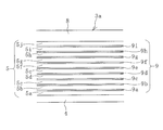
- FIG. 2 is an explanatory view illustrating a body portion of the pneumatic fender of FIG.
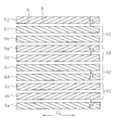
- FIG. 3 is an explanatory view illustrating the extension direction of the cords of the respective reinforcing layers in plan view.
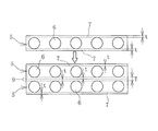
- FIG. 4 is an explanatory view illustrating the laminated state of the reinforcing layer in an enlarged scale and in a cross-sectional view.
- FIG. 5 is an explanatory view illustrating a side view of the pneumatic fender of FIG. 1 in which a predetermined internal pressure is applied to the main body to expand the body into a predetermined shape, with a part of the member of the body part cut away.
- the pneumatic fender 1 of the present invention illustrated in FIGS. 1 to 3 is a body 2 in which a bowl-shaped mirror portion 3b is connected to both ends of a cylindrical body portion 3a. , And the base portion 10 provided on the main body 2.
- the base portion 10 is provided on the one mirror portion 3b, but it may be provided on both side mirror portions 3b.
- the main body 2 is configured by laminating a plurality of reinforcing layers 5 between an inner rubber layer 4 and an outer rubber layer 8.
- ten reinforcing layers 5 (5a to 5j) are laminated.
- the number of stacked reinforcing layers 5 is, for example, in the range of 6 or more and 18 or less.
- Each reinforcing layer 5 is formed by a large number of cords 6.
- the cord 6 a steel cord, an organic fiber cord or the like is used.
- the outer diameter of the cord 6 is, for example, in the range of 0.5 mm or more and 1.5 mm or less.
- An intermediate rubber layer 9 (9a-9i) is interposed between the reinforcing layers 5.
- the rubber forming the intermediate rubber layer 9 for example, natural rubber, butyl rubber, styrene butadiene rubber, acrylonitrile butadiene rubber or the like is used.
- the layer thickness of the intermediate rubber layer 9 is, for example, less than 1 mm in the neutral state where the main body 2 is not expanded, and more preferably 0.2 mm or more and 0.6 mm or less.
- the neutral state in which the main body 2 is not expanded is a state in which tension is not substantially generated in the cord 6, and air is injected into the main body 2, but the internal pressure is slightly higher than the atmospheric pressure. (For example, 10 kPa). Then, the body portion 3a holds the cylindrical shape, and the mirror portion 3b holds the bowl shape.
- the outer diameter of the body portion 3a in the neutral state where the body 2 is not expanded is, for example, in the range of 2 m or more and 8 m or less.
- the rubber forming the inner layer rubber 4 for example, natural rubber, butyl rubber, styrene butadiene rubber, acrylonitrile butadiene rubber, etc. are used.
- the rubber forming the outer layer rubber 8 for example, natural rubber, styrene butadiene rubber, acrylonitrile butadiene rubber, ethylene propylene rubber or the like is used.
- the layer thickness of the inner rubber layer 4 is in the range of 2 mm or more and 5 mm or less
- the layer thickness of the outer rubber layer 8 is in the range of 3 mm or more and 12 mm or less.
- each reinforcing layer 5 is formed by a large number of cords 6 which are aligned and extend in parallel with each other at a predetermined cord angle A with respect to the cylinder axis direction CL.
- this fender 1 as shown in FIG. 3, two adjacent reinforcing layers that are laminated are one set S, and have a plurality of sets S (S1 to S4).
- Each set S is composed of reinforcing layers 5 different from each other.
- four sets S1 to S4 are formed by eight reinforcing layers 5b to 5i other than the innermost reinforcing layer 5a and the outermost reinforcing layer 5j.
- the number of sets S is, for example, about 3 to 6, and preferably a plurality.
- each set S1, S2, S3, S4 (every one set S), the cords 6 of each reinforcing layer 5 extend in the same direction at a predetermined cord angle A.
- the cords 6 of the reinforcing layers 5 extend at a predetermined cord angle A in the intersecting direction. That is, in the sets S1 and S2, the cords 6 of the reinforcing layers 5 extend in the intersecting direction, and in the sets S2 and S3, the cords 6 of the reinforcing layers 5 extend in the intersecting direction, and the set S3.
- the cords 6 of the reinforcing layers 5 extend in the intersecting direction. Therefore, the cords 6 of the reinforcing layers 5 of the sets S1 and S3 extend parallel to each other, and the cords 6 of the reinforcing layers 5 of the sets S2 and S4 extend parallel to each other.
- the cords 6 of the reinforcing layers 5b, 5c, 5f, and 5g extend at the cord angle A inclined in the same direction.
- the cords 6 of the reinforcing layers 5d, 5e, 5h, and 5i extend at the cord angle A inclined in the same direction.
- the cords 6 of the reinforcing layers 5b, 5c, 5f, 5g and the cords 6 of the reinforcing layers 5d, 5e, 5h, 5i extend in directions intersecting with each other. That is, in the body portion 3a, the cord 6 has a bias structure with the set S as a unit.
- the cords 6 of the reinforcing layer 5a at the innermost circumference extend at a cord angle A while being inclined in a direction intersecting with the cords 6 of the reinforcing layers 5b adjacent to each other.
- the cords 6 of the outermost reinforcing layer 5j extend at a cord angle A while being inclined in a direction intersecting the cords 6 of the reinforcing layers 5i that are stacked and adjacent to each other.
- the cord angle A of each reinforcing layer 5 is set to 25° or more and 45° or less. More preferably, the code angle A is set to 30° or more and 35° or less.
- the mirror portion 3b may be configured such that the reinforcing layer 5 of the body portion 3a extends to both ends in the cylinder axis direction. That is, the entire main body 2 can have a bias structure.
- the mirror portion 3b is formed by alternately stacking a reinforcing layer formed by the cords 6 extending radially around the base portion 10 and a reinforcing layer formed by the cords 6 extending in the circumferential direction. It can also be configured.
- the internal pressure of the main body 2 is set to a low pressure of, for example, about 10 kPa, and it is in a non-expanded neutral state as illustrated in FIG. Further, the air inside the main body 2 is discharged to be in a folded state.
- the main body 2 When the fender 1 is attached to the installation location and used, the main body 2 is expanded and maintained in a predetermined shape as illustrated in FIG. Specifically, a prescribed internal pressure P is loaded by filling the inside of the main body 2 with air through a valve installed in the mouthpiece part 10.
- the specified internal pressure P is, for example, about 50 kPa to 100 kPa.
- each reinforcing layer 5 in the body portion 3a increases to a stationary angle (54° to 55°) at which the cord angle A is stable.
- the intermediate rubber layer 9b interposed between these reinforcing layers 5 The shearing force does not substantially act on 9d, 9f, and 9h.
- the intermediate rubber layers 9c, 9e, 9g interposed between the sets S are formed. Is subjected to shearing force and undergoes shear deformation. In this embodiment, the intermediate rubber layers 9a and 9i also undergo shear deformation. In this way, when the prescribed internal pressure P is applied to the main body 2, the cord angles A of the respective reinforcing layers 5 in the body portion 3a increase to a stable stationary angle (54° to 55°) and the main body 2 Expands and remains in the desired shape.
- the outer diameter of the body portion 3a can be set within a range of 120% or more and 150% or less with respect to the neutral state when the prescribed internal pressure P is applied.
- the axial length of the main body 2 (body portion 3a) is in the range of 95% or less and 80% or more with respect to the neutral state.
- the layer thickness T of each intermediate rubber layer 9 is preferably 0.2 mm or more and less than 1 mm, more preferably 0.2 mm or more and 0.6 mm.
- the cord angle A is less than 25° in the neutral state, excessive shear stress is generated in the intermediate rubber layers 9c, 9e, 9g and the intermediate rubber layers 9a, 9i in order to increase the cord angle A to a rest angle. Since it is not preferable, it is set to 25° or more, more preferably 30° or more. If the cord angle A exceeds 45°, the degree of expansion of the diameter of the body portion 3a when the main body 2 is loaded with the prescribed internal pressure P from the neutral state is reduced, so it is set to 45° or less, more preferably 35° or less.
- the layer thickness T of all the intermediate rubber layers 9 is the same in the neutral state where the main body 2 is not expanded, but the present invention is not limited to this.
- the layer thicknesses T of the intermediate rubber layers 9b, 9d, 9f and 9h interposed between the reinforcing layers 5 of each one set S are stacked and adjacent to each other. It is also possible to have a specification that is set smaller than the layer thickness T of the intermediate rubber layers 9c, 9e, 9g interposed between them.
- the shearing force substantially acts on the intermediate rubber layers 9c, 9e, 9g. Therefore, according to this specification, it is ensured that the main body 2 is smoothly expanded to a predetermined shape.
- the weight can be reduced.
- a shearing force also acts on the intermediate rubber layers 9a and 9i, so that the intermediate rubber layers 9a and 9i may have the same thickness as the intermediate rubber layers 9c, 9e, and 9g.
- the layer thickness T of all the intermediate rubber layers 9 becomes the same. Therefore, for example, when laminating the reinforcing layers 5b and 5c that are in the same set S, a rubber layer is added between these layers. Rubber layers may be similarly added between the reinforcing layer 5d and the reinforcing layer 5e, between the reinforcing layer 5f and the reinforcing layer 5g, and between the reinforcing layer 5h and the reinforcing layer 5i.
- the innermost peripheral reinforcing layer 5a and the outermost peripheral reinforcing layer 5j can also be configured to form the set S.
- the set S is made by the reinforcing layers 5b to 5i other than the innermost reinforcing layer 5a and the outermost reinforcing layer 5j as in this embodiment. Should be configured.
Landscapes
- Engineering & Computer Science (AREA)
- General Engineering & Computer Science (AREA)
- Ocean & Marine Engineering (AREA)
- Mechanical Engineering (AREA)
- Environmental & Geological Engineering (AREA)
- Civil Engineering (AREA)
- Structural Engineering (AREA)
- Chemical & Material Sciences (AREA)
- Combustion & Propulsion (AREA)
- Laminated Bodies (AREA)
Abstract
本体に規定内圧を負荷した際に、より円滑に膨張するとともに所定形状を確保できる空気式防舷材を提供する。本体2が中立状態でコード角度Aが25°以上45°以下に設定されている各補強層5は、本体2に規定内圧Pを負荷すると、互いの補強層5のコード6が交差する方向に延在している隣り合うセットSどうしの間に介在する中間ゴム層9c、9e、9gがせん断変形してコード角度Aが安定な静止角程度まで大きくなって、膨張した本体2は所定形状を維持し、積層されて隣り合う2層の補強層5どうしからなる各1つのセットSでは、各補強層5のコード6どうしは所定のコード角度Aで同じ方向に延在しているので、これら補強層5の間に介在する中間ゴム層9b、9d、9f、9hにはせん断力が実質的に作用しないので、本体2を膨張させる際の抵抗が小さくなる。
Description
本発明は、空気式防舷材に関し、さらに詳しくは、規定内圧を負荷した際に、より円滑に膨張するとともに所定形状を確保できる空気式防舷材に関するものである。
空気式防舷材は、一般的に円筒状の胴部の両端にボウル状の鏡部を備えた本体を有していて、本体は内層ゴムと外層ゴムとの間に複数の補強層が積層されて構成されている。胴部では、それぞれの補強層は多数のコードが平行に引き揃えられて形成されていて、そのコードは筒軸方向に対して所定のコード角度で配置されている。積層されて隣り合う補強層どうしのコードは交差した状態(いわゆるバイアス構造)になっている。本体を膨張させていない中立状態でのコード角度が静止角程度(54°~55°)に設定されている場合は、本体の内部に空気を充填して規定内圧を負荷しても本体の大きさ(長さおよび外径)は、それ程変化しない。
本体を膨張させていない中立状態で、胴部のそれぞれの補強層のコード角度を15°~45°に設定することで、本体に規定内圧を負荷した際により大きく膨張させることができる構造も提案されている(特許文献1参照)。この構造では、本体に規定内圧を負荷すると、胴部のそれぞれの補強層のコード角度が静止角程度になるまで本体が膨張して所定形状に維持される。しかしながら、本体が膨張する際に、積層されて隣り合う補強層どうしの間の中間ゴム層にせん断力が作用する。これに伴い、それぞれの中間ゴム層が本体を膨張させる際の大きな抵抗になるため、本体を円滑に膨張させるには不利になる。
本発明の目的は、規定内圧を負荷した際に、より円滑に膨張するとともに所定形状を確保できる空気式防舷材を提供することにある。
上記目的を達成するため本発明の空気式防舷材は、円筒状の胴部とこの胴部の両端に連接されたボウル状の鏡部とを有する本体を備え、前記本体が内層ゴムと外層ゴムとの間に複数の補強層が積層されて構成されていて、前記胴部では、それぞれの前記補強層は筒軸方向に対して所定のコード角度で平行に引き揃えられて延在する多数のコードにより形成されていて、それぞれの前記補強層の間に中間ゴム層が介在している空気式防舷材において、前記胴部で積層されて隣り合う2層の前記補強層どうしが1つのセットになり、このセットを複数有してそれぞれの前記セットどうしが互いに異なる前記補強層により構成されていて、それぞれの1つの前記セットではそれぞれの前記補強層の前記コードどうしは同じ方向に延在していて、積層されて隣り合う前記セットどうしでは互いの前記補強層の前記コードが交差する方向に延在している構造を有し、
前記本体を膨張させていない中立状態で前記胴部のそれぞれの前記補強層の前記コード角度が25°以上45°以下に設定されていることを特徴とする。
前記本体を膨張させていない中立状態で前記胴部のそれぞれの前記補強層の前記コード角度が25°以上45°以下に設定されていることを特徴とする。
本発明によれば、本体を膨張させていない中立状態で、胴部のそれぞれの補強層のコード角度が25°以上45°以下に設定されているので、本体に空気を充填して規定内圧にすると、胴部のそれぞれの補強層のコード角度が安定な静止角程度まで大きくなって、膨張した本体を所定形状に確保することができる。それぞれの1つの前記セットではそれぞれの補強層のコードどうしは所定のコード角度で同じ方向に延在しているので、本体が膨張する際には、これら補強層の間に介在する中間ゴム層にはせん断力が実質的に作用しない。積層されて隣り合う前記セットどうしでは互いの補強層のコードが交差する方向に延在している。したがって、本体が膨張する際には、セットの積層構造に存在している中間ゴム層のうち、積層されて隣り合うセットどうしの間に介在する中間ゴム層にだけに実質的にせん断力が作用するので、本体を膨張させる際の抵抗が小さくなり、本体を円滑に膨張させるには有利になる。
以下、本発明の空気式防舷材を図に示した実施形態に基づいて説明する。
図1~図3に例示する本発明の空気式防舷材1(以下、防舷材1という)は、円筒状の胴部3aの両端にボウル状の鏡部3bが連接された本体2と、本体2に設けられた口金部10とを備えている。この実施形態では、一方の鏡部3bに口金部10が設けられているが、両側の鏡部3bに設けられることもある。
本体2は、内層ゴム4と外層ゴム8との間に複数の補強層5が積層されて構成されている。この実施形態では10層の補強層5(5a~5j)が積層されている。補強層5の積層数は例えば6以上18以下の範囲程度である。それぞれの補強層5は多数のコード6により形成されている。コード6としては、スチールコードや有機繊維コード等が用いられる。コード6の外径は、例えば0.5mm以上1.5mm以下の範囲程度である。
それぞれの補強層5どうしの間には中間ゴム層9(9a~9i)が介在している。中間ゴム層9を形成するゴムとしては、例えば天然ゴム、ブチルゴム、スチレンブタジエンゴム、アクリロニトリルブタジエンゴム等が用いられる。中間ゴム層9の層厚は例えば、本体2を膨張させていない中立状態で1mm未満であり、より好ましくは0.2mm以上0.6mm以下である。
本体2を膨張させていない中立状態とは、コード6に実質的にテンションが生じていない状態であり、本体2の内部に空気が注入されているが、その内圧が大気圧よりも若干高い程度(例えば、10kPa)である。そして、胴部3aが円筒状の形態を保持するとともに鏡部3bがボウル状の形態を保持している状態である。本体2を膨張させていない中立状態での胴部3aの外径は、例えば2m以上8m以下の範囲程度である。
内層ゴム4を形成するゴムとしては、例えば天然ゴム、ブチルゴム、スチレンブタジエンゴム、アクリロニトリルブタジエンゴム等が用いられる。外層ゴム8を形成するゴムとしては、例えば天然ゴム、スチレンブタジエンゴム、アクリロニトリルブタジエンゴム、エチレンプロピレンゴム等が用いられる。本体2を膨張させていない中立状態では、内層ゴム4の層厚は例えば2mm以上5mm以下の範囲程度、外層ゴム8の層厚は例えば3mm以上12mm以下の範囲程度である。
胴部3aでは、それぞれの補強層5は、筒軸方向CLに対して所定のコード角度Aで平行に引き揃えられて延在する多数のコード6により形成されている。この防舷材1では図3に例示するように、積層されて隣り合う2層の補強層どうしが1つのセットSになっていて、複数のセットS(S1~S4)を有している。それぞれのセットSどうしは、互いに異なる補強層5により構成されている。この実施形態では、最内周の補強層5aおよび最外周の補強層5j以外の8層の補強層5b~5iによって4つのセットS1~S4が構成されている。セットSの数は例えば3~6程度であり、複数にすることが好ましい。
それぞれのセットS1、S2、S3、S4(1つのセットS毎)では、それぞれの補強層5のコード6どうしは同じ方向に所定のコード角度Aで延在している。積層されて隣り合うセットSどうしでは、互いの補強層5のコード6が交差する方向に所定のコード角度Aで延在している。即ち、セットS1とS2とでは互いの補強層5のコード6が交差する方向に延在し、セットS2とS3とでは互いの補強層5のコード6が交差する方向に延在し、セットS3とS4とでは互いの補強層5のコード6が交差する方向に延在している。したがって、セットS1とS3とでは互いの補強層5のコード6が平行に延在し、セットS2とS4とでは互いの補強層5のコード6が平行に延在している。
詳述すると、補強層5b、5c、5f、5gのそれぞれのコード6は、同じ方向に傾斜したコード角度Aで延在している。補強層5d、5e、5h、5iのそれぞれのコード6は、同じ方向に傾斜したコード角度Aで延在している。そして、補強層5b、5c、5f、5gのそれぞれのコード6と、補強層5d、5e、5h、5iのそれぞれのコード6とは、互いに交差する方向に延在している。即ち、この胴部3aは、セットSを単位としてコード6がバイアス構造になっている。
この実施形態では、最内周の補強層5aのコード6は、積層されて隣り合う補強層5bのコード6とは交差する方向に傾斜してコード角度Aで延在している。最外周の補強層5jのコード6は、積層されて隣り合う補強層5iのコード6とは交差する方向に傾斜してコード角度Aで延在している。
本体2を膨張させていない中立状態では、それぞれの補強層5のコード角度Aは25°以上45°以下に設定されている。より好ましくは、コード角度Aは30°以上35°以下に設定される。
図4に例示するように、それぞれの補強層5は、層厚tのコートゴム7によってコード6が被覆されている。したがって、胴部3aの成形時に、これら補強層5が単純に積層されると、補強層5どうしの間の中間ゴム層9の層厚Tは、コートゴム7の層厚tの2倍になる(T=2t)。
鏡部3bは、胴部3aの補強層5を筒軸方向両端部まで延在させるようにして構成することもできる。即ち、本体2の全体をバイアス構造にすることもできる。或いは、鏡部3bは、口金部10を中心して放射状に延在するコード6で形成された補強層と、円周方向に延在するコード6で形成された補強層とを交互に積層して構成することもできる。
防舷材1を保管、運搬、設置する時などの使用していない時は、本体2の内圧を例えば10kPa程度の低圧にして、図1に例示するように膨張させていない中立状態にする。さらには、本体2の内部の空気を排出して折り畳んだ状態にする。
防舷材1を設置場所に取付けて使用する場合は、図5に例示するように本体2を膨張させて所定形状に維持する。具体的には、口金部10に設置されたバルブを通じて、本体2の内部に空気を充填して規定内圧Pを負荷する。規定内圧Pは、例えば50kPa~100kPa程度である。
本体2の内部に空気を充填して規定内圧Pに到達する過程で、胴部3aでは、それぞれの補強層5は、コード角度Aが安定な静止角程度(54°~55°)まで大きくなろうとする。ここで、それぞれの1つのセットSではそれぞれの補強層5のコード6どうしは所定のコード角度Aで同じ方向に延在しているので、これら補強層5の間に介在する中間ゴム層9b、9d、9f、9hにはせん断力が実質的に作用しない。
一方、胴部3aで積層されて隣り合うセットSどうしの補強層5のコード6は交差する方向に延在しているので、セットSどうしの間に介在する中間ゴム層9c、9e、9gにはせん断力が作用してせん断変形する。この実施形態では、中間ゴム層9a、9iもせん断変形する。このようにして、本体2に規定内圧Pを負荷した際には、胴部3aではそれぞれの補強層5のコード角度Aが安定な静止角程度(54°~55°)まで大きくなって本体2は膨張し、所定形状に維持される。
即ち、本体2が膨張する際には、セットSの積層構造に注目すると、中間ゴム層9b~9hのうち、積層されて隣り合うセットSどうしの間に介在する中間ゴム層9c、9e、9gにだけに実質的にせん断力が作用する。そのため、中間ゴム層9b~9hのすべてにせん断力が作用する場合に比して、本体2を膨張させる際の抵抗が小さくなり、本体2を円滑に膨張させるには有利になる。
胴部3aの外径は、規定内圧Pを負荷した際には中立状態に対して120%以上150%以下の範囲程度にすることが可能になる。本体2(胴部3a)の軸方向長さは、規定内圧Pを負荷した際には中立状態に対して95%以下80%以上の範囲程度になる。
中間ゴム層9の層厚が0.2mm未満では、本体2が膨張する際にせん断力が作用する中間ゴム層9(9c、9e、9g)に対する負荷が過大になる。また、中間ゴム層9の層厚が1mm以上では、防舷材1の重量が過大になる。それ故、それぞれの中間ゴム層9の層厚Tは0.2mm以上1mm未満にすることが好ましく、より好ましくは0.2mm以上0.6mmにする。
また、中立状態においてコード角度Aが25°未満では、コード角度Aを静止角程度に大きくするには中間ゴム層9c、9e、9g、および中間ゴム層9a、9iに過大なせん断応力が生じて好ましくないので25°以上、より好ましくは30°以上にする。このコード角度Aが45°超では、本体2を中立状態から規定内圧Pを負荷した際の胴部3aの拡径具合が小さくなるので、45°以下、より好ましくは35°以下にする。
この実施形態では、本体2を膨張させていない中立状態で、すべての中間ゴム層9の層厚Tが同じになっているがこれに限定されない。本体2を膨張させていない中立状態で、それぞれの1つのセットSの補強層5どうしの間に介在する中間ゴム層9b、9d、9f、9hの層厚Tが、積層されて隣り合うセットSどうしの間に介在する中間ゴム層9c、9e、9gの層厚Tよりも小さく設定された仕様にすることもできる。本体2が膨張する際に、せん断力が実質的に作用するのは、中間ゴム層9c、9e、9gなので、この仕様によれば、本体2を円滑に所定形状まで膨張させることを確保しながら、軽量化を図ることができる。尚、本体2が膨張する際に、中間ゴム層9a、9iにもせん断力が作用するので、中間ゴム層9a、9iの層厚は、中間ゴム層9c、9e、9gと同じにするとよい。
図4に例示するように、胴部3aの成形時に、同じ仕様の補強層5(コートゴム7の層厚t)を単純に積層すると、すべての中間ゴム層9の層厚Tが同じになる。そこで例えば、同じセットSになる補強層5b、5cを積層する際にこれらの層間にゴム層を追加する。補強層5dと補強層5eとの層間、補強層5fと補強層5gの層間、補強層5hと補強層5iとの層間にも同様にゴム層を追加すればよい。
最内周の補強層5aおよび最外周の補強層5jも、セットSを構成する構造にすることもできる。ただし、補強層5の数が増加すると防舷材1の軽量化には不利になる。したがって、防舷材1に要求される耐圧性が確保できるのであれば、この実施形態のように、最内周の補強層5aおよび最外周の補強層5j以外の補強層5b~5iによってセットSを構成するとよい。
1 空気式防舷材
2 本体
3a 胴部
3b 鏡部
4 内層ゴム
5(5a~5j) 補強層
6 コード
7 コートゴム
8 外層ゴム
9(9a~9i) 中間ゴム層
10 口金部
A コード角度
S(S1、S2、S3、S4)補強層のセット
2 本体
3a 胴部
3b 鏡部
4 内層ゴム
5(5a~5j) 補強層
6 コード
7 コートゴム
8 外層ゴム
9(9a~9i) 中間ゴム層
10 口金部
A コード角度
S(S1、S2、S3、S4)補強層のセット
Claims (5)
- 円筒状の胴部とこの胴部の両端に連接されたボウル状の鏡部とを有する本体を備え、前記本体が内層ゴムと外層ゴムとの間に複数の補強層が積層されて構成されていて、前記胴部では、それぞれの前記補強層は筒軸方向に対して所定のコード角度で平行に引き揃えられて延在する多数のコードにより形成されていて、それぞれの前記補強層の間に中間ゴム層が介在している空気式防舷材において、
前記胴部で積層されて隣り合う2層の前記補強層どうしが1つのセットになり、このセットを複数有してそれぞれの前記セットどうしが互いに異なる前記補強層により構成されていて、それぞれの1つの前記セットではそれぞれの前記補強層の前記コードどうしは同じ方向に延在していて、積層されて隣り合う前記セットどうしでは互いの前記補強層の前記コードが交差する方向に延在している構造を有し、
前記本体を膨張させていない中立状態で前記胴部のそれぞれの前記補強層の前記コード角度が25°以上45°以下に設定されていることを特徴とする空気式防舷材。 - 前記中立状態で、前記胴部のそれぞれの前記中間ゴム層の層厚が0.2mm以上1mm未満である請求項1に記載の空気式防舷材。
- 前記中立状態で、それぞれの1つの前記セットの前記補強層どうしの間に介在する前記中間ゴム層の層厚が、積層されて隣り合う前記セットどうしの間に介在する前記中間ゴム層の層厚よりも小さく設定されている請求項1または2に記載の空気式防舷材。
- 最内周および最外周の前記補強層以外の前記胴部の前記補強層によって前記セットが構成されている請求項1~3のいずれかに記載の空気式防舷材。
- 前記セットの数が6以下である請求項1~4のいずれかに記載の空気式防舷材。
Priority Applications (3)
| Application Number | Priority Date | Filing Date | Title |
|---|---|---|---|
| US17/413,732 US11486108B2 (en) | 2019-01-09 | 2019-11-12 | Pneumatic fender |
| CN201980080049.3A CN113167041B (zh) | 2019-01-09 | 2019-11-12 | 充气式护舷材 |
| KR1020217013961A KR102312345B1 (ko) | 2019-01-09 | 2019-11-12 | 공기식 방현재 |
Applications Claiming Priority (2)
| Application Number | Priority Date | Filing Date | Title |
|---|---|---|---|
| JP2019001649A JP7180386B2 (ja) | 2019-01-09 | 2019-01-09 | 空気式防舷材 |
| JP2019-001649 | 2019-01-09 |
Publications (1)
| Publication Number | Publication Date |
|---|---|
| WO2020144934A1 true WO2020144934A1 (ja) | 2020-07-16 |
Family
ID=71520709
Family Applications (1)
| Application Number | Title | Priority Date | Filing Date |
|---|---|---|---|
| PCT/JP2019/044350 Ceased WO2020144934A1 (ja) | 2019-01-09 | 2019-11-12 | 空気式防舷材 |
Country Status (5)
| Country | Link |
|---|---|
| US (1) | US11486108B2 (ja) |
| JP (1) | JP7180386B2 (ja) |
| KR (1) | KR102312345B1 (ja) |
| CN (1) | CN113167041B (ja) |
| WO (1) | WO2020144934A1 (ja) |
Families Citing this family (4)
| Publication number | Priority date | Publication date | Assignee | Title |
|---|---|---|---|---|
| JP7180386B2 (ja) * | 2019-01-09 | 2022-11-30 | 横浜ゴム株式会社 | 空気式防舷材 |
| JP2024027678A (ja) * | 2022-08-18 | 2024-03-01 | 横浜ゴム株式会社 | ゴム製品およびその製造方法 |
| JP2024062051A (ja) * | 2022-10-24 | 2024-05-09 | 横浜ゴム株式会社 | 空気式防舷材の管理システムおよび方法 |
| KR20250165893A (ko) | 2024-05-20 | 2025-11-27 | 탬프주식회사 | 팬더 핸드링 장비 |
Citations (4)
| Publication number | Priority date | Publication date | Assignee | Title |
|---|---|---|---|---|
| JPH0633433A (ja) * | 1992-07-15 | 1994-02-08 | Bridgestone Corp | 気体封入式防舷装置 |
| JP2006291628A (ja) * | 2005-04-13 | 2006-10-26 | Yokohama Rubber Co Ltd:The | 空気式防舷材 |
| JP2014218866A (ja) * | 2013-05-10 | 2014-11-20 | 横浜ゴム株式会社 | 縦型空気式防舷材 |
| US20150114274A1 (en) * | 2012-05-11 | 2015-04-30 | D.B.M. Fabriek En Handelsonderneming B.V. | Fender, maritime structure, method for manufacturing |
Family Cites Families (27)
| Publication number | Priority date | Publication date | Assignee | Title |
|---|---|---|---|---|
| NL130258C (ja) * | 1965-07-28 | |||
| US3881974A (en) * | 1971-04-28 | 1975-05-06 | Establissments Michelin Raison | Tire having two-ply carcass merging into one ply |
| US4176858A (en) * | 1974-01-04 | 1979-12-04 | Safety Consultants | Energy absorbing bumper system |
| DE2653022C3 (de) * | 1976-11-22 | 1979-09-20 | Schroecker, Erika, Zuerich (Schweiz) | Verfahren und Vorrichtung zum Herstellen eines Rohlings für einen Radial-Gürtelreifen |
| JPS5928689B2 (ja) * | 1978-03-03 | 1984-07-14 | 株式会社ブリヂストン | 円筒胴を受衝面とする空気式防げん材 |
| KR830000618A (ko) * | 1979-03-03 | 1983-04-16 | 시바모또 시게마사 | 공기식 방현재 |
| JPS60229806A (ja) * | 1984-04-27 | 1985-11-15 | Yokohama Rubber Co Ltd:The | 空気入りタイヤ |
| JP2727111B2 (ja) * | 1989-04-28 | 1998-03-11 | 株式会社ブリヂストン | 空気式防舷材の製造方法 |
| US5117864A (en) * | 1991-09-16 | 1992-06-02 | Byers Richard V | Valve seal tool |
| US5560312A (en) * | 1995-10-20 | 1996-10-01 | Mcpherson; Sarah A. | Fenders for watercraft |
| KR100255444B1 (ko) * | 1997-09-26 | 2000-05-01 | 조원영 | 공기식 방충재 제조 방법 |
| US7478658B2 (en) * | 2006-07-31 | 2009-01-20 | Bridgestone Firestone North American Tire, Llc | Tire having a carcass ply turn-up portion with a concave segment |
| US20130105056A1 (en) * | 2011-10-28 | 2013-05-02 | Joseph Kevin Hubbell | Tire having modular ply construction and method of making same |
| JP2013189526A (ja) * | 2012-03-13 | 2013-09-26 | Yokohama Rubber Co Ltd:The | 熱可塑性エラストマー組成物 |
| JP5565434B2 (ja) * | 2012-04-27 | 2014-08-06 | 横浜ゴム株式会社 | 空気式防舷材 |
| JP5790637B2 (ja) * | 2012-12-20 | 2015-10-07 | 横浜ゴム株式会社 | 空気式防舷材 |
| KR101348277B1 (ko) | 2013-09-26 | 2014-01-08 | 주식회사 씨앤텍 | 펜더제조방법 |
| US9816241B2 (en) * | 2014-03-31 | 2017-11-14 | The Yokohama Rubber Co., Ltd. | Pneumatic fender and mouth piece metal for pneumatic fender |
| US10472885B2 (en) * | 2014-06-16 | 2019-11-12 | Sharp Kabushiki Kaisha | Daylighting member, method of manufacturing daylighting member, daylighting device, and daylighting device installation method |
| CN204982793U (zh) * | 2015-07-10 | 2016-01-20 | 山东龙奥橡塑有限公司 | 一种潜水艇用充气护舷 |
| CN107850095A (zh) * | 2015-07-14 | 2018-03-27 | 株式会社普利司通 | 流体压致动器 |
| JP6604141B2 (ja) * | 2015-10-23 | 2019-11-13 | 住友ゴム工業株式会社 | エアレスタイヤ |
| US10023278B1 (en) * | 2016-09-20 | 2018-07-17 | Gideon Smith | Pneumatic fender system for vessels |
| US10639934B2 (en) * | 2016-11-22 | 2020-05-05 | The Goodyear Tire & Rubber Company | Shear band for a structurally supported tire |
| JP6785190B2 (ja) * | 2017-06-12 | 2020-11-18 | 株式会社ブリヂストン | タイヤ |
| WO2019012871A1 (ja) * | 2017-07-12 | 2019-01-17 | 横浜ゴム株式会社 | 空気式防舷材 |
| JP7180386B2 (ja) * | 2019-01-09 | 2022-11-30 | 横浜ゴム株式会社 | 空気式防舷材 |
-
2019
- 2019-01-09 JP JP2019001649A patent/JP7180386B2/ja active Active
- 2019-11-12 US US17/413,732 patent/US11486108B2/en active Active
- 2019-11-12 CN CN201980080049.3A patent/CN113167041B/zh active Active
- 2019-11-12 KR KR1020217013961A patent/KR102312345B1/ko active Active
- 2019-11-12 WO PCT/JP2019/044350 patent/WO2020144934A1/ja not_active Ceased
Patent Citations (4)
| Publication number | Priority date | Publication date | Assignee | Title |
|---|---|---|---|---|
| JPH0633433A (ja) * | 1992-07-15 | 1994-02-08 | Bridgestone Corp | 気体封入式防舷装置 |
| JP2006291628A (ja) * | 2005-04-13 | 2006-10-26 | Yokohama Rubber Co Ltd:The | 空気式防舷材 |
| US20150114274A1 (en) * | 2012-05-11 | 2015-04-30 | D.B.M. Fabriek En Handelsonderneming B.V. | Fender, maritime structure, method for manufacturing |
| JP2014218866A (ja) * | 2013-05-10 | 2014-11-20 | 横浜ゴム株式会社 | 縦型空気式防舷材 |
Also Published As
| Publication number | Publication date |
|---|---|
| JP7180386B2 (ja) | 2022-11-30 |
| CN113167041B (zh) | 2022-05-10 |
| CN113167041A (zh) | 2021-07-23 |
| JP2020111893A (ja) | 2020-07-27 |
| KR20210061444A (ko) | 2021-05-27 |
| US20220042264A1 (en) | 2022-02-10 |
| US11486108B2 (en) | 2022-11-01 |
| KR102312345B1 (ko) | 2021-10-13 |
Similar Documents
| Publication | Publication Date | Title |
|---|---|---|
| JP7180386B2 (ja) | 空気式防舷材 | |
| JP6136556B2 (ja) | 縦型空気式防舷材 | |
| AU2013253477B2 (en) | Pneumatic fender | |
| JPWO2019012871A1 (ja) | 空気式防舷材 | |
| WO2020148983A1 (ja) | 空気式防舷材およびその製造方法 | |
| WO2019244737A1 (ja) | 空気入りタイヤ | |
| JP2023087586A (ja) | 吸音具及び組立体 | |
| WO2020045284A1 (ja) | タイヤ | |
| JPH0292704A (ja) | 空気入りタイヤ |
Legal Events
| Date | Code | Title | Description |
|---|---|---|---|
| 121 | Ep: the epo has been informed by wipo that ep was designated in this application |
Ref document number: 19908516 Country of ref document: EP Kind code of ref document: A1 |
|
| ENP | Entry into the national phase |
Ref document number: 20217013961 Country of ref document: KR Kind code of ref document: A |
|
| NENP | Non-entry into the national phase |
Ref country code: DE |
|
| 122 | Ep: pct application non-entry in european phase |
Ref document number: 19908516 Country of ref document: EP Kind code of ref document: A1 |