WO2020138338A1 - 燃料電池の活性化方法及び活性化装置 - Google Patents
燃料電池の活性化方法及び活性化装置 Download PDFInfo
- Publication number
- WO2020138338A1 WO2020138338A1 PCT/JP2019/051244 JP2019051244W WO2020138338A1 WO 2020138338 A1 WO2020138338 A1 WO 2020138338A1 JP 2019051244 W JP2019051244 W JP 2019051244W WO 2020138338 A1 WO2020138338 A1 WO 2020138338A1
- Authority
- WO
- WIPO (PCT)
- Prior art keywords
- gas
- cathode
- fuel cell
- anode
- electrode
- Prior art date
- Legal status (The legal status is an assumption and is not a legal conclusion. Google has not performed a legal analysis and makes no representation as to the accuracy of the status listed.)
- Ceased
Links
Images


Classifications
-
- H—ELECTRICITY
- H01—ELECTRIC ELEMENTS
- H01M—PROCESSES OR MEANS, e.g. BATTERIES, FOR THE DIRECT CONVERSION OF CHEMICAL ENERGY INTO ELECTRICAL ENERGY
- H01M8/00—Fuel cells; Manufacture thereof
- H01M8/04—Auxiliary arrangements, e.g. for control of pressure or for circulation of fluids
- H01M8/04298—Processes for controlling fuel cells or fuel cell systems
- H01M8/04694—Processes for controlling fuel cells or fuel cell systems characterised by variables to be controlled
- H01M8/04858—Electric variables
- H01M8/04895—Current
- H01M8/0491—Current of fuel cell stacks
-
- H—ELECTRICITY
- H01—ELECTRIC ELEMENTS
- H01M—PROCESSES OR MEANS, e.g. BATTERIES, FOR THE DIRECT CONVERSION OF CHEMICAL ENERGY INTO ELECTRICAL ENERGY
- H01M8/00—Fuel cells; Manufacture thereof
- H01M8/04—Auxiliary arrangements, e.g. for control of pressure or for circulation of fluids
- H01M8/04082—Arrangements for control of reactant parameters, e.g. pressure or concentration
- H01M8/04089—Arrangements for control of reactant parameters, e.g. pressure or concentration of gaseous reactants
- H01M8/04119—Arrangements for control of reactant parameters, e.g. pressure or concentration of gaseous reactants with simultaneous supply or evacuation of electrolyte; Humidifying or dehumidifying
- H01M8/04126—Humidifying
-
- H—ELECTRICITY
- H01—ELECTRIC ELEMENTS
- H01M—PROCESSES OR MEANS, e.g. BATTERIES, FOR THE DIRECT CONVERSION OF CHEMICAL ENERGY INTO ELECTRICAL ENERGY
- H01M8/00—Fuel cells; Manufacture thereof
- H01M8/04—Auxiliary arrangements, e.g. for control of pressure or for circulation of fluids
- H01M8/04082—Arrangements for control of reactant parameters, e.g. pressure or concentration
- H01M8/04197—Preventing means for fuel crossover
-
- H—ELECTRICITY
- H01—ELECTRIC ELEMENTS
- H01M—PROCESSES OR MEANS, e.g. BATTERIES, FOR THE DIRECT CONVERSION OF CHEMICAL ENERGY INTO ELECTRICAL ENERGY
- H01M8/00—Fuel cells; Manufacture thereof
- H01M8/04—Auxiliary arrangements, e.g. for control of pressure or for circulation of fluids
- H01M8/04082—Arrangements for control of reactant parameters, e.g. pressure or concentration
- H01M8/04201—Reactant storage and supply, e.g. means for feeding, pipes
-
- H—ELECTRICITY
- H01—ELECTRIC ELEMENTS
- H01M—PROCESSES OR MEANS, e.g. BATTERIES, FOR THE DIRECT CONVERSION OF CHEMICAL ENERGY INTO ELECTRICAL ENERGY
- H01M8/00—Fuel cells; Manufacture thereof
- H01M8/04—Auxiliary arrangements, e.g. for control of pressure or for circulation of fluids
- H01M8/04223—Auxiliary arrangements, e.g. for control of pressure or for circulation of fluids during start-up or shut-down; Depolarisation or activation, e.g. purging; Means for short-circuiting defective fuel cells
- H01M8/04225—Auxiliary arrangements, e.g. for control of pressure or for circulation of fluids during start-up or shut-down; Depolarisation or activation, e.g. purging; Means for short-circuiting defective fuel cells during start-up
-
- H—ELECTRICITY
- H01—ELECTRIC ELEMENTS
- H01M—PROCESSES OR MEANS, e.g. BATTERIES, FOR THE DIRECT CONVERSION OF CHEMICAL ENERGY INTO ELECTRICAL ENERGY
- H01M8/00—Fuel cells; Manufacture thereof
- H01M8/04—Auxiliary arrangements, e.g. for control of pressure or for circulation of fluids
- H01M8/04223—Auxiliary arrangements, e.g. for control of pressure or for circulation of fluids during start-up or shut-down; Depolarisation or activation, e.g. purging; Means for short-circuiting defective fuel cells
- H01M8/04231—Purging of the reactants
-
- H—ELECTRICITY
- H01—ELECTRIC ELEMENTS
- H01M—PROCESSES OR MEANS, e.g. BATTERIES, FOR THE DIRECT CONVERSION OF CHEMICAL ENERGY INTO ELECTRICAL ENERGY
- H01M8/00—Fuel cells; Manufacture thereof
- H01M8/04—Auxiliary arrangements, e.g. for control of pressure or for circulation of fluids
- H01M8/04223—Auxiliary arrangements, e.g. for control of pressure or for circulation of fluids during start-up or shut-down; Depolarisation or activation, e.g. purging; Means for short-circuiting defective fuel cells
- H01M8/04238—Depolarisation
-
- H—ELECTRICITY
- H01—ELECTRIC ELEMENTS
- H01M—PROCESSES OR MEANS, e.g. BATTERIES, FOR THE DIRECT CONVERSION OF CHEMICAL ENERGY INTO ELECTRICAL ENERGY
- H01M8/00—Fuel cells; Manufacture thereof
- H01M8/04—Auxiliary arrangements, e.g. for control of pressure or for circulation of fluids
- H01M8/04223—Auxiliary arrangements, e.g. for control of pressure or for circulation of fluids during start-up or shut-down; Depolarisation or activation, e.g. purging; Means for short-circuiting defective fuel cells
- H01M8/04268—Heating of fuel cells during the start-up of the fuel cells
-
- H—ELECTRICITY
- H01—ELECTRIC ELEMENTS
- H01M—PROCESSES OR MEANS, e.g. BATTERIES, FOR THE DIRECT CONVERSION OF CHEMICAL ENERGY INTO ELECTRICAL ENERGY
- H01M8/00—Fuel cells; Manufacture thereof
- H01M8/04—Auxiliary arrangements, e.g. for control of pressure or for circulation of fluids
- H01M8/04298—Processes for controlling fuel cells or fuel cell systems
- H01M8/043—Processes for controlling fuel cells or fuel cell systems applied during specific periods
- H01M8/04302—Processes for controlling fuel cells or fuel cell systems applied during specific periods applied during start-up
-
- H—ELECTRICITY
- H01—ELECTRIC ELEMENTS
- H01M—PROCESSES OR MEANS, e.g. BATTERIES, FOR THE DIRECT CONVERSION OF CHEMICAL ENERGY INTO ELECTRICAL ENERGY
- H01M8/00—Fuel cells; Manufacture thereof
- H01M8/04—Auxiliary arrangements, e.g. for control of pressure or for circulation of fluids
- H01M8/04298—Processes for controlling fuel cells or fuel cell systems
- H01M8/04313—Processes for controlling fuel cells or fuel cell systems characterised by the detection or assessment of variables; characterised by the detection or assessment of failure or abnormal function
- H01M8/04537—Electric variables
- H01M8/04544—Voltage
- H01M8/04559—Voltage of fuel cell stacks
-
- H—ELECTRICITY
- H01—ELECTRIC ELEMENTS
- H01M—PROCESSES OR MEANS, e.g. BATTERIES, FOR THE DIRECT CONVERSION OF CHEMICAL ENERGY INTO ELECTRICAL ENERGY
- H01M8/00—Fuel cells; Manufacture thereof
- H01M8/04—Auxiliary arrangements, e.g. for control of pressure or for circulation of fluids
- H01M8/04298—Processes for controlling fuel cells or fuel cell systems
- H01M8/04694—Processes for controlling fuel cells or fuel cell systems characterised by variables to be controlled
- H01M8/04701—Temperature
- H01M8/04708—Temperature of fuel cell reactants
-
- H—ELECTRICITY
- H01—ELECTRIC ELEMENTS
- H01M—PROCESSES OR MEANS, e.g. BATTERIES, FOR THE DIRECT CONVERSION OF CHEMICAL ENERGY INTO ELECTRICAL ENERGY
- H01M8/00—Fuel cells; Manufacture thereof
- H01M8/04—Auxiliary arrangements, e.g. for control of pressure or for circulation of fluids
- H01M8/04298—Processes for controlling fuel cells or fuel cell systems
- H01M8/04694—Processes for controlling fuel cells or fuel cell systems characterised by variables to be controlled
- H01M8/04701—Temperature
- H01M8/04731—Temperature of other components of a fuel cell or fuel cell stacks
-
- H—ELECTRICITY
- H01—ELECTRIC ELEMENTS
- H01M—PROCESSES OR MEANS, e.g. BATTERIES, FOR THE DIRECT CONVERSION OF CHEMICAL ENERGY INTO ELECTRICAL ENERGY
- H01M8/00—Fuel cells; Manufacture thereof
- H01M8/04—Auxiliary arrangements, e.g. for control of pressure or for circulation of fluids
- H01M8/04298—Processes for controlling fuel cells or fuel cell systems
- H01M8/04694—Processes for controlling fuel cells or fuel cell systems characterised by variables to be controlled
- H01M8/04746—Pressure; Flow
- H01M8/04753—Pressure; Flow of fuel cell reactants
-
- H—ELECTRICITY
- H01—ELECTRIC ELEMENTS
- H01M—PROCESSES OR MEANS, e.g. BATTERIES, FOR THE DIRECT CONVERSION OF CHEMICAL ENERGY INTO ELECTRICAL ENERGY
- H01M8/00—Fuel cells; Manufacture thereof
- H01M8/04—Auxiliary arrangements, e.g. for control of pressure or for circulation of fluids
- H01M8/04298—Processes for controlling fuel cells or fuel cell systems
- H01M8/04694—Processes for controlling fuel cells or fuel cell systems characterised by variables to be controlled
- H01M8/04791—Concentration; Density
- H01M8/04798—Concentration; Density of fuel cell reactants
-
- H—ELECTRICITY
- H01—ELECTRIC ELEMENTS
- H01M—PROCESSES OR MEANS, e.g. BATTERIES, FOR THE DIRECT CONVERSION OF CHEMICAL ENERGY INTO ELECTRICAL ENERGY
- H01M8/00—Fuel cells; Manufacture thereof
- H01M8/04—Auxiliary arrangements, e.g. for control of pressure or for circulation of fluids
- H01M8/04298—Processes for controlling fuel cells or fuel cell systems
- H01M8/04694—Processes for controlling fuel cells or fuel cell systems characterised by variables to be controlled
- H01M8/04828—Humidity; Water content
- H01M8/04835—Humidity; Water content of fuel cell reactants
-
- H—ELECTRICITY
- H01—ELECTRIC ELEMENTS
- H01M—PROCESSES OR MEANS, e.g. BATTERIES, FOR THE DIRECT CONVERSION OF CHEMICAL ENERGY INTO ELECTRICAL ENERGY
- H01M8/00—Fuel cells; Manufacture thereof
- H01M8/10—Fuel cells with solid electrolytes
- H01M2008/1095—Fuel cells with polymeric electrolytes
-
- H—ELECTRICITY
- H01—ELECTRIC ELEMENTS
- H01M—PROCESSES OR MEANS, e.g. BATTERIES, FOR THE DIRECT CONVERSION OF CHEMICAL ENERGY INTO ELECTRICAL ENERGY
- H01M8/00—Fuel cells; Manufacture thereof
- H01M8/04—Auxiliary arrangements, e.g. for control of pressure or for circulation of fluids
- H01M8/04082—Arrangements for control of reactant parameters, e.g. pressure or concentration
- H01M8/04089—Arrangements for control of reactant parameters, e.g. pressure or concentration of gaseous reactants
- H01M8/04104—Regulation of differential pressures
-
- H—ELECTRICITY
- H01—ELECTRIC ELEMENTS
- H01M—PROCESSES OR MEANS, e.g. BATTERIES, FOR THE DIRECT CONVERSION OF CHEMICAL ENERGY INTO ELECTRICAL ENERGY
- H01M8/00—Fuel cells; Manufacture thereof
- H01M8/04—Auxiliary arrangements, e.g. for control of pressure or for circulation of fluids
- H01M8/04298—Processes for controlling fuel cells or fuel cell systems
- H01M8/04694—Processes for controlling fuel cells or fuel cell systems characterised by variables to be controlled
- H01M8/04746—Pressure; Flow
- H01M8/04783—Pressure differences, e.g. between anode and cathode
-
- Y—GENERAL TAGGING OF NEW TECHNOLOGICAL DEVELOPMENTS; GENERAL TAGGING OF CROSS-SECTIONAL TECHNOLOGIES SPANNING OVER SEVERAL SECTIONS OF THE IPC; TECHNICAL SUBJECTS COVERED BY FORMER USPC CROSS-REFERENCE ART COLLECTIONS [XRACs] AND DIGESTS
- Y02—TECHNOLOGIES OR APPLICATIONS FOR MITIGATION OR ADAPTATION AGAINST CLIMATE CHANGE
- Y02E—REDUCTION OF GREENHOUSE GAS [GHG] EMISSIONS, RELATED TO ENERGY GENERATION, TRANSMISSION OR DISTRIBUTION
- Y02E60/00—Enabling technologies; Technologies with a potential or indirect contribution to GHG emissions mitigation
- Y02E60/30—Hydrogen technology
- Y02E60/50—Fuel cells
Definitions
- the present invention relates to a fuel cell activation method and an activation device. More specifically, the present invention relates to a method and an apparatus for activating a fuel cell including an electrolyte layer containing a solid polymer and an anode electrode and a cathode electrode provided on both sides of the electrolyte layer.
- a fuel cell is formed by sandwiching an electrolyte membrane/electrode structure (so-called MEA) formed by disposing an electrolyte layer containing a solid polymer between an anode electrode and a cathode electrode with a pair of separators. .. Further, the fuel cell stack is configured by stacking a plurality of such fuel cells, and is mounted, for example, as a power source of a vehicle.
- MEA electrolyte membrane/electrode structure
- the power generation performance immediately after assembling the fuel cell or the fuel cell stack (hereinafter, these are also simply referred to as "fuel cell” unless it is necessary to distinguish between the cell and the stack) is low. Therefore, after the fuel cell is assembled, various activation treatments (aging) are performed in order to enhance its power generation performance.
- the fuel cell can be activated by a simple activation device
- hydrogen cross- leaks from the anode electrode to the cathode electrode and the anode electrode Since the potential difference between the cathode electrode and the cathode electrode becomes small, the aging effect is low, and activation may take time.
- hydrogen remaining on the cathode electrode directly reacts with oxygen in the air newly supplied to the cathode electrode, The heat generation may deteriorate the fuel cell.
- An object of the present invention is to provide an activation method and an activation device that can activate the fuel cell in a short time while suppressing deterioration of the fuel cell.
- a method for activating a fuel cell is an electrolyte layer containing a solid polymer (for example, an electrolyte membrane 24 described below) and the electrolyte.
- a fuel cell including an anode electrode (for example, an anode electrode 25 described later) provided on one surface of the layer and a cathode electrode (for example, a cathode electrode 26 described below) provided on the other surface of the electrolyte layer.
- a cathode electrode for example, a cathode electrode 26 described below
- a first energizing step of electrically connecting and energizing the anode electrode and the cathode electrode via an external electric load for example, an external electric load 6 described later
- an external electric load for example, an external electric load 6 described later
- a potential difference is generated between the anode electrode and the cathode electrode.
- a mixture of an oxidant gas and an inert gas is supplied to the cathode electrode as a gas on the cathode side, and the first energizing step transitions to the second energizing step. In doing so, it is preferable to turn off the supply of the oxidant gas while continuing the supply of the inert gas.
- the second energization step is performed, after the state in which the potential difference between the anode electrode and the cathode electrode is equal to or less than the predetermined voltage continues for a predetermined time, the second energization step is performed. It is preferable to shift to the first energization step.
- the activation device (for example, the activation device 3 described later) of the fuel cell (for example, the fuel cell 2 and the fuel cell stack 1 described later) according to the present invention has an electrolyte layer (for example, an activation device 3 described below) containing a solid polymer.
- a cathode electrode 26 for activating a fuel cell, the external electrical load (for example, an external electrical load 6 described later) electrically connecting the anode electrode and the cathode electrode, and hydrogen gas.
- a hydrogen gas supply source for example, a hydrogen gas supply source 41 described later for supplying the gas, and an anode-side gas supply path (for example, a hydrogen gas supply path 42 described later) that connects the anode electrode and the hydrogen gas supply source.
- An oxidant gas supply source for example, an air pump 51 described below
- an inert gas supply source for example, a nitrogen gas supply source 52 described below
- a cathode-side gas supply path (for example, a cathode-side gas supply path 54 described later) that connects the oxidant gas supply source and the inert gas supply source, and an oxidant from the oxidant gas supply source to the cathode electrode.
- a control means for example, a control device 53 described later for alternately turning on or off the supply of gas.
- the activation device further includes a voltage sensor (for example, a cell voltage sensor 7 described later) that detects a potential difference between the anode electrode and the cathode electrode, and the control unit includes the oxidation unit. It is preferable that the supply of the oxidant gas is turned on after the state in which the potential difference is lowered to the predetermined voltage or lower continues for a predetermined time while the supply of the agent gas is turned off.
- a voltage sensor for example, a cell voltage sensor 7 described later
- both electrodes are supplied with an external electric load in a state where a potential difference is generated between the two electrodes by supplying hydrogen gas to the anode electrode and oxidizing gas to the cathode electrode.
- a second energizing step of electrically connecting and energizing via the external electric load, thereby activating the fuel cell.
- the activation method of the present invention as compared with the activation method described in Patent Document 1 (hereinafter, also referred to as "conventional activation method") that intermittently supplies air to the cathode electrode,
- the fuel cell can be activated in a short time while suppressing the deterioration of the fuel cell.
- a potential difference can be generated between the two electrodes by utilizing the difference in hydrogen concentration between the anode electrode supplied with hydrogen gas and the cathode electrode supplied with inert gas.
- both electrodes are electrically connected via an external electric load in the state where the current occurs, both electrodes are energized with a smaller current and a smaller amount of supplied anode gas and cathode gas than in normal power generation. It will be possible.
- the water produced by the electrode reaction due to the difference in hydrogen concentration can be supplied to the electrode catalyst and the electrolyte layer included in the anode electrode and the cathode electrode, so that the electrolyte layer can be kept in a wet state and good protons can be obtained. It is possible to generate conductivity and to supply water to the three-phase interface of the electrode catalyst, the electrolyte layer, and the hydrogen gas or the oxidant gas, which become the reaction site during power generation of the fuel cell, and thus, to make the fuel cell efficient. Can be activated.
- the activation method of the present invention since the cross leak from the anode electrode can be suppressed by supplying the inert gas in the second energization step, the hydrogen concentration difference can be kept high, and the high activation effect can be obtained. Can be maintained. Further, in the activation method of the present invention, since the cross leak can be suppressed in this way, the direct reaction between the oxidant gas and hydrogen can be suppressed, and consequently the deterioration of the fuel cell can also be suppressed. Therefore, according to the activation method of the present invention, it is possible to activate the fuel cell in a shorter time than the conventional activation method while suppressing the deterioration of the fuel cell.
- the first energizing step and the second energizing step are alternately repeated a plurality of times, so that the fuel cell is activated more quickly than when both steps are performed once. Can be converted.
- the first energization step a mixture of an oxidant gas and an inert gas is supplied to the cathode electrode as a gas on the cathode side, and the first energization step to the second energization step.
- the first energizing step and the second energizing step can be alternately repeated a plurality of times only by alternately turning on and off the supply of the oxidant gas, so that a simple configuration is achieved.
- the fuel cell can be activated with.
- the activation method of the present invention during the second energizing step, the state in which the potential difference between both electrodes is equal to or lower than the predetermined voltage continues for a predetermined time, and then the second energizing step transitions to the first energizing step.
- the fuel cell can be made into a hydrogen concentration cell for an appropriate time, so that the fuel cell can be efficiently activated.
- an external electric load that electrically connects the anode electrode and the cathode electrode, and a cathode-side gas supply that connects the cathode electrode to the oxidant gas supply source and the inert gas supply source
- a control means for alternately turning on and off the supply of the oxidant gas from the oxidant gas supply source to the cathode electrode.
- the control means turns on the supply of the oxidant gas after the state in which the potential difference has dropped to the predetermined voltage or less continues for a predetermined time when the supply of the oxidant gas is turned off.
- the fuel cell can be a hydrogen concentration cell for an appropriate period of time, so that the fuel cell can be efficiently activated.
- FIG. 6 is a flowchart showing a specific procedure of an activation method according to an embodiment of the present invention. It is a figure which shows an example of a change of the cell average voltage of a fuel cell stack at the time of performing a 1st electricity supply process after performing a 2nd electricity supply process.
- FIG. 1 is a diagram showing a configuration of the fuel cell stack 1 and its activation device 3.
- the fuel cell stack 1 is configured by stacking a plurality of fuel battery cells 2.
- FIG. 1 shows only a part of the plurality of fuel cells 2. In the following, the case of activating the fuel cell stack 1 will be described, but the present invention is not limited to this.
- the present invention may activate the individual fuel cells 2 that make up the fuel cell stack 1.
- the fuel cell 2 includes an electrolyte membrane/electrode structure 21 (hereinafter, referred to as “MEA 21”), and a first separator 22 and a second separator 23 that sandwich the MEA 21.
- the MEA 21 includes, for example, an electrolyte membrane 24 as an electrolyte layer containing a solid polymer such as a perfluorosulfonic acid thin film, an anode electrode 25 provided on one surface of the electrolyte membrane 24, and the other surface of the electrolyte membrane 25. And a cathode electrode 26 provided in the.
- the anode electrode 25 is a porous body including a first electrode catalyst layer 25a facing one surface of the electrolyte membrane 24 and a first gas diffusion layer 25b laminated on the first electrode catalyst layer 25a.
- the cathode electrode 26 is a porous body including a second electrode catalyst layer 26a facing the other surface of the electrolyte membrane 24 and a second gas diffusion layer 26b laminated on the second electrode catalyst layer 26a.
- the first electrode catalyst layer 25a and the second electrode catalyst layer 26a include, for example, catalyst particles (electrode catalyst) configured by supporting a catalyst metal such as platinum on a carbon catalyst carrier such as carbon black (electrode catalyst), and high ion conductivity. And a molecular binder.
- the electrode catalyst may be made of only a catalyst metal such as platinum black and may not include a catalyst carrier.
- Electrodes such as 2Pt+H 2 O+1/2O 2 +e ⁇ ⁇ 2Pt(OH ⁇ ), Pt(OH ⁇ )+H 3 O + ⁇ Pt+2H 2 O, etc. Occurs.
- This electrode reaction is promoted by supplying water to the surface of the electrode catalyst and allowing water to exist at the three-phase interface.
- the three-phase interface is the interface between the electrode catalyst serving as a reaction site, the electrolyte membrane 24, and the hydrogen gas or the oxidant gas during the actual power generation of the fuel cell stack 1.
- the anode side gas containing hydrogen gas is supplied to the anode electrode 25 and the cathode side gas containing oxidant gas is supplied to the cathode electrode 26. The time to actually get power from.
- the first gas diffusion layer 25b and the second gas diffusion layer 26b are made of, for example, carbon paper or carbon cloth.
- the first gas diffusion layer 25b is arranged so as to face the first separator 22, and the second gas diffusion layer 26b is arranged so as to face the second separator 23.
- carbon separators are used as the first separator 22 and the second separator 23, for example, metal separators may be used instead.
- An anode side gas inlet communication hole (not shown) for supplying the anode side gas and an anode side gas for discharging the anode side gas are formed on the surface of the first separator 22 facing the first gas diffusion layer 25b.
- An anode-side gas flow channel 27 that communicates with the outlet communication hole (not shown) is formed.
- a cathode-side gas inlet communication hole (not shown) for supplying the cathode-side gas and a cathode-side gas for discharging the cathode-side gas are formed on the surface of the second separator 23 facing the second gas diffusion layer 26b.
- a cathode-side gas flow channel 28 that communicates with the outlet communication hole (not shown) is formed.
- a cooling medium inlet communication hole for supplying a cooling medium is provided between the surfaces of the first separator 22 and the second separator 23 of each fuel cell 2 that face each other.
- a cooling medium outlet communication hole for discharging this cooling medium are integrally formed with a coolant passage 29.
- the activation device 3 supplies the anode gas to the anode gas passage 27 of the fuel cell stack 1 and the cathode gas to the cathode gas passage 28 of the fuel cell stack 1.
- the device 8 is provided.
- the external electric load 6 electrically connects the anode electrode 25 and the cathode electrode 26 of the fuel cell stack 1 and energizes between the electrodes 25, 26.
- the external electric load 6 supplies the anode-side gas from the anode-side gas supply device 4 to the anode electrode 25 and the cathode-side gas from the cathode-side gas supply device 5 to the cathode electrode 26.
- a potential difference occurs between the cathode electrode 26 and the anode electrode 26
- a current flows from the cathode electrode 26 to the anode electrode 25.
- this external electric load 6 it is possible to maintain the current flowing between the electrodes 25 and 26 at a predetermined magnitude.
- the cell voltage sensor 7 detects a cell voltage generated between the anode electrode 25 and the cathode electrode 26 for each fuel battery cell 2, and outputs a detection signal corresponding to the magnitude of the cell voltage to the cathode side gas supply device 5. To a control device 53, which will be described later.
- the cell average voltage which is the average of the cell voltages of the fuel cells 2, is calculated by the control device 53 based on the detection signal from the cell voltage sensor 7.
- the temperature adjusting device 8 adjusts the temperature of the fuel cell stack 1 by supplying the heat transfer medium adjusted to a predetermined temperature to the refrigerant passage 29 of the fuel cell stack 1.
- the anode-side gas supply device 4 supplies the anode-side gas containing hydrogen gas to the anode-side gas flow path 27.
- the anode-side gas supply device 4 includes a hydrogen gas supply source 41 that supplies hydrogen gas, a hydrogen gas supply path 42 that connects the hydrogen gas supply source 41 and the anode-side gas flow path 27, and the hydrogen gas supply path 42.
- the provided anode side humidifier 43 is provided.
- the hydrogen gas supply source 41 includes a hydrogen gas tank (not shown) that stores hydrogen gas at a high pressure, and a flow rate adjusting valve (not shown) that adjusts the flow rate of the hydrogen gas supplied from the hydrogen gas tank to the hydrogen gas supply passage 42. ) Etc.
- the hydrogen gas supply path 42 is a pipe connecting the hydrogen gas supply source 41 and the anode gas flow path 27, and guides the hydrogen gas supplied from the hydrogen gas supply source 41 to the anode gas flow path 27.
- the anode side humidifier 43 mixes the hydrogen gas supplied from the hydrogen gas supply source 41 and water vapor, and adjusts the dew point of the anode side gas.
- the anode-side gas supply device 4 uses the hydrogen gas supply source 41, the hydrogen gas supply path 42, and the anode-side humidifier 43 to discharge the anode-side gas adjusted to a predetermined dew point at a predetermined flow rate. Supply to the gas flow path 27.
- the cathode-side gas supply device 5 supplies the cathode-side gas including air as an oxidant gas and nitrogen gas as an inert gas to the cathode-side gas flow path 28.
- the cathode side gas supply device 5 includes an air pump 51 for supplying air, a nitrogen gas supply source 52 for supplying nitrogen gas, a control device 53 for controlling the air pump 51, the air pump 51, the nitrogen gas supply source 52, and the cathode.
- the cathode-side gas supply path 54 that connects the side-side gas flow path 28, and the cathode-side humidifier 55 and the mixer 56 provided in the cathode-side gas supply path 54 are provided.
- the cathode-side gas supply passage 54 has a first passage 54a that connects the air pump 51 and the cathode-side gas passage 28, and a second passage 54b that connects the nitrogen gas supply source 52 and the first passage 54a. Equipped with.
- the air pump 51 compresses air according to a command from the control device 53, and supplies the compressed air to the cathode-side gas passage 28 via the first passage 54a.
- the control device 53 adjusts the flow rate of the air supplied to the first flow path 54a by controlling the rotation speed of the air pump 51.
- the control device 53 can alternately turn on or off the supply of air from the air pump 51 to the cathode-side gas passage 28. Note that, in the present embodiment, a case will be described in which the control device 53 controls the rotation speed of the air pump 51 to alternately turn on or off the supply of air from the air supply source to the cathode-side gas flow channel 28.
- the present invention is not limited to this.
- a flow rate control valve When a flow rate control valve is provided in the air flow path that connects the air supply source and the cathode side gas flow path 28, the opening of the flow rate control valve is controlled so that the air supply source moves to the cathode side.
- the supply of air to the gas passage 28 may be alternately turned on or off.
- the nitrogen gas supply source 52 includes a nitrogen gas tank (not shown) that stores nitrogen gas at a high pressure, and a flow rate adjusting valve (not shown) that adjusts the flow rate of the nitrogen gas supplied from the nitrogen gas tank to the second flow path 54b. ) Etc.
- the cathode-side humidifier 55 is provided in the first flow path 54a, mixes the air supplied from the air pump 51 with water vapor, and adjusts the dew point of the air flowing through the first flow path 54a.
- the mixer 56 is provided on the cathode-side gas passage 28 side of the first passage 54a with respect to the cathode-side humidifier 55.
- the mixer 56 mixes the air supplied from the air pump 51 via the first flow path 54a and the nitrogen gas supplied from the nitrogen gas supply source 52 via the second flow path 54b, and the cathode side gas flow. Supply to the path 28.
- the cathode side gas supply device 5 is adjusted to a predetermined dew point by using the air pump 51, the nitrogen gas supply source 52, the control device 53, the cathode side gas supply passage 54, the cathode side humidifier 55, and the mixer 56.
- the cathode side gas is supplied to the cathode side gas passage 28 at a predetermined flow rate.
- FIG. 2 is a flowchart showing a specific procedure of the activation method according to this embodiment.
- the anode electrode 25 and the cathode electrode 26 of the fuel cell stack 1 are electrically connected by the external electric load 6.
- the fuel cell stack 1 is maintained at a predetermined temperature by supplying the heat transfer medium adjusted to a predetermined temperature to the refrigerant passage 29 of the fuel cell stack 1 by the temperature adjusting device 8.
- the first energization process is executed for a predetermined time.
- the anode gas is supplied from the anode gas supply device 4 to the anode gas flow path 27, and the cathode gas is supplied from the cathode gas supply device 5 to the cathode gas flow path 28.
- a potential difference is generated between the anode electrode 25 and the cathode electrode 26, and the electrodes 25, 26 are energized via the external electric load 6.
- the anode gas supply device 4 supplies the anode gas, which has a predetermined dew point by mixing hydrogen gas and water vapor, to the anode gas flow passage 27 at a predetermined flow rate. ..
- the cathode-side gas supply device 5 uses the mixture of air adjusted to a predetermined dew point and a predetermined flow rate and nitrogen gas adjusted to a predetermined flow rate as the cathode-side gas. Supply to the gas flow path 28.
- the anode side gas supply device 4 and the cathode side supply device 5 are arranged so that the pressure difference between the anode side gas flow passage 27 and the cathode side gas flow passage 28 is maintained at a predetermined value. Anode side gas and cathode side gas are supplied.
- the anode side gas containing hydrogen gas is supplied to the anode electrode 25, and the cathode side gas containing the oxidant gas is supplied to the cathode electrode 26, so that the fuel cell stack 1 performs normal power generation.
- This is a so-called normal power generation aging step that promotes activation of the fuel cell stack 1 by performing it.
- the second energization process is executed for a predetermined time.
- the anode side gas is supplied from the anode side gas supply apparatus 4 to the anode side gas flow path 27, and at the same time as the above-described first energization step from the cathode side gas supply apparatus 5 to the cathode side gas flow path 28.
- the cathode side gas of different components By supplying the cathode side gas of different components, a potential difference is generated between the anode electrode 25 and the cathode electrode 26, and the electrodes 25, 26 are energized via the external electric load 6.
- the flow rate ratio of air and nitrogen gas (flow rate of air/flow rate of nitrogen gas) in the cathode side gas supplied to the cathode side gas flow path 28 is smaller in the second energizing step than in the first energizing step. Is set to. As will be described later with reference to Example 4, more efficient activation can be realized as the flow rate ratio between the air of the cathode side gas and the nitrogen gas in the second energization step is reduced. Therefore, in the following, when the flow rate ratio of the air of the cathode side gas and the nitrogen gas supplied to the cathode side gas flow path 28 in the second energization step is set to 0 (that is, the air supply in the second energization step is turned off. However, the present invention is not limited to this.
- the anode gas supply device 4 supplies the anode gas, which has a predetermined dew point by mixing hydrogen gas and water vapor, to the anode gas flow passage 27 at a predetermined flow rate. ..
- the flow rate and dew point of the anode gas in the second energizing step are preferably the same as those in the first energizing step. Therefore, when the first energization process and the second energization process are alternately repeated, it is preferable to continue supplying the anode gas, which has a predetermined dew point, to the anode gas passage 27 at a constant flow rate. ..
- the cathode side gas supply device 5 supplies the nitrogen gas adjusted to a predetermined flow rate to the cathode side gas passage 28 as the cathode side gas.
- the flow rate of nitrogen gas in the second energizing step is preferably equal to the flow rate of nitrogen gas in the first energizing step. Therefore, when the first energization process and the second energization process are alternately repeated, it is preferable to continue supplying the nitrogen gas from the nitrogen gas supply source 52 to the cathode side gas passage 28 at a constant flow rate.
- the air supply from the air pump 51 can be turned off by the control device 53 while continuously supplying the nitrogen gas at a constant flow rate as described above. preferable. Further, when the second energization process is transitioned to the first energization process, it is preferable that the controller 53 turn on the air supply from the air pump 51.
- the anode side gas supply device 4 and the cathode side supply device 5 have the same pressure difference between the anode side gas passage 27 and the cathode side gas passage 28 as in the first energization step. The anode side gas and the cathode side gas are supplied so as to be maintained at a predetermined value.
- the anode side gas containing hydrogen gas is supplied to the anode electrode 25, and the cathode side gas containing the inert gas but not the oxidant gas is supplied to the cathode electrode 26, so that both electrodes 25 , 26, a hydrogen concentration difference is generated, and the fuel cell stack 1 is used as a hydrogen concentration cell to promote activation of the fuel cell stack 1.
- This is a so-called hydrogen concentration cell aging step.
- S5 it is determined whether or not the first energization process and the second energization process have been repeatedly executed a predetermined number of times. If the determination result in S5 is NO, the process returns to S3 and the first energization process and the second energization process are executed again. If the determination result in S6 is YES, the activation method of FIG. 2 ends.
- the set number of times is an integer of 2 or more and the first energization process and the second energization process are alternately repeated a plurality of times.
- FIG. 3 is a diagram showing an example of changes in the cell average voltage of the fuel cell stack 1 when the first energization process is executed after the second energization process is executed. More specifically, FIG. 3 is a diagram showing an example of changes in the cell average voltage when the fuel cell stack 1 is activated according to Example 1 described later.
- the first energizing step is executed until time t0
- the first energizing step is shifted to the second energizing step at time t0
- the second energizing step is shifted to the first energizing step at time t2.
- the case where the first energization process is completed at time t3 is shown.
- the control device 53 uses the external electrical load in the first energization process. It may be changed to a value smaller than the current consumption (more specifically, a value slightly larger than 0).
- the control device 53 uses the external electrical load in the first energization process. If the value is changed to a value smaller than the current consumption (more specifically, a value slightly larger than 0), the current consumption may be increased.
- the fuel cell stack 1 is activated by alternately and repeatedly executing the first energization process and the second energization process as described above a plurality of times.
- the control device 53 causes the cathode-side gas flow path 28 after the state in which the cell average voltage detected by the cell voltage sensor 7 is equal to or lower than the predetermined determination voltage continues for the predetermined time during the second energization process.
- the determination voltage is a threshold value set for the cell average voltage to determine that the fuel cell stack 1 has become a hydrogen concentration cell, and is set to a value slightly larger than 0.
- the activation method and the activation device 3 according to the present embodiment have the following effects.
- (1) in the activation method according to the present embodiment, by supplying hydrogen gas to the anode electrode 25 and supplying air to the cathode electrode 26, a potential difference is generated between the electrodes 25, 26.
- the first energization step of electrically connecting 25 and 26 through the external electric load 6 and energizing them, and by supplying hydrogen gas to the anode electrode 25 and nitrogen gas to the cathode electrode 26, both electrodes 25, 26
- the fuel cell stack 1 is activated by executing a second energization step of electrically connecting both electrodes through the external electric load 6 and energizing them while a potential difference is generated between the electrodes 26.
- the fuel cell stack 1 is prevented from deteriorating while the fuel is consumed in a short time.
- the battery stack 1 can be activated.
- a potential difference can be generated between the electrodes 25 and 26 by utilizing the hydrogen concentration difference between the anode electrode 25 supplied with hydrogen gas and the cathode electrode 26 supplied with nitrogen gas.
- the water produced by the electrode reaction due to the difference in hydrogen concentration can be supplied to the electrode catalyst and the electrolyte layer included in the anode electrode 25 and the cathode electrode 26, so that the electrolyte membrane 24 is kept in a wet state. It is possible to generate good proton conductivity, and to supply water to the three-phase interface between the electrode catalyst, which serves as a reaction site during the power generation of the fuel cell stack 1, the electrolyte membrane 24, and hydrogen gas or air, and thus the fuel cell.
- the stack 1 can be efficiently activated.
- the hydrogen concentration difference can be maintained at a high level and, as a result, a high activation effect can be obtained. Can be maintained.
- the cross leak can be suppressed as described above, the direct reaction between air and hydrogen can be suppressed, and thus the deterioration of the fuel cell stack 1 can be suppressed. Therefore, according to the activation method according to the present embodiment, the fuel cell stack 1 can be activated in a shorter time than the conventional activation method while suppressing the deterioration of the fuel cell stack 1.
- the first energization process and the second energization process are alternately repeated a plurality of times, so that the fuel cell can be swiftly compared with the case where both processes are performed once. Can be activated.
- the first energization step a mixture of air and nitrogen gas is supplied to the cathode electrode 26 as the cathode side gas, and the first energization step to the second energization step.
- the air supply is turned off while continuing the nitrogen gas supply. Therefore, in the activation method according to the present embodiment, the first energizing step and the second energizing step can be alternately repeated a plurality of times only by alternately repeating the air supply on and off, so that a simple configuration is achieved.
- the fuel cell stack 1 can be activated.
- the second energization step is performed after the state in which the potential difference between the electrodes 25 and 26 is equal to or less than the predetermined determination voltage continues for a predetermined time.
- the fuel cell stack 1 can be made into a hydrogen concentration cell for an appropriate time, so that the fuel cell stack 1 can be efficiently activated.
- the activation device 3 connects the external electric load 6 that electrically connects the anode electrode 25 and the cathode electrode 26, the cathode electrode 26, the air pump 51, and the nitrogen gas supply source 52.
- a cathode side gas supply passage 54 and a controller 53 for alternately turning on and off the supply of air from the air pump 51 to the cathode electrode 26 are provided.
- the control device 53 alternately turns on or off the supply of air, so that the first energization process and the second energization process are alternately repeated a plurality of times. Therefore, the fuel cell stack 1 can be efficiently activated while suppressing the deterioration of the fuel cell stack 1 as described above.
- the control device 53 reduces the cell average voltage detected using the cell voltage sensor 7 when the air supply is turned off to be equal to or lower than a predetermined determination voltage. After the state continues for a predetermined time, the air supply is turned on. As a result, the fuel cell stack 1 can be used as a hydrogen concentration cell for an appropriate time, so that the fuel cell stack 1 can be efficiently activated.
- Example 1 In Example 1, the activation device 3 was connected to the fuel cell stack 1 of 10 cells, and the first energization process and the second energization process were alternately repeated based on the activation method of FIG. At this time, the temperature of the fuel cell stack 1 was maintained at 70° C. by using the temperature adjusting device 8. Further, in Example 1, by using the anode side gas supply device 4, hydrogen gas humidified to have a dew point of 70° C. was supplied to the anode side gas passage 27 as the anode side gas. Here, the flow rate of hydrogen gas was set to 0.3 [NL/min].
- Example 1 by using the cathode side gas supply device 5, a mixture of air and nitrogen gas humidified to have a dew point of 70° C. was supplied to the cathode side gas passage 28 as the cathode side gas. ..
- the flow rate of air was 0.7 [NL/min]
- the flow rate of nitrogen gas was 1.4 [NL/min].
- the first energization step and the second energization step are performed by switching the supply of air from on to off or from off to on every minute while continuously supplying the nitrogen gas at the above flow rate. Alternating 1 minute each, 30 times each. That is, the time required for activation in Example 1 was 1 hour in total.
- the anode-side gas supply device 4 and the cathode-side gas supply device 5 are connected between the anode-side gas passage 27 and the cathode-side gas passage 28 during the first energization process and the second energization process.
- the anode side gas and the cathode side gas were supplied so that the pressure difference was maintained at a predetermined value.
- Comparative Example 1 In Comparative Example 1, the activation device 3 was connected to the fuel cell stack 1 of 10 cells, and only the first energization step in the activation method of FIG. 2 was executed. At this time, the temperature of the fuel cell stack 1 was maintained at 70° C. by using the temperature adjusting device 8.
- the anode-side gas supply device 4 hydrogen gas humidified to have a dew point of 70° C. was supplied to the anode-side gas flow channel 27 as the anode-side gas. Further, in Comparative Example 1, by using the cathode side gas supply device 5, air humidified to have a dew point of 70° C. was supplied to the cathode side gas passage 28 as the cathode side gas.
- the flow rate of hydrogen gas was 20 [NL/min] and the flow rate of air was 50 [NL/min], and a current of 150 [A] was continuously drawn between the electrodes 25 and 26 for a total of 1 hour.
- the activation time is the same in Comparative Example 1 and Example 1, but the amount of hydrogen gas used and the current are larger in Comparative Example 1 than in Example 1.
- Comparative Example 1 is different from Example 1 in that the second energization step is not included.
- Comparative example 2 In Comparative Example 2, the activation device 3 was connected to the fuel cell stack 1 of 10 cells, and only the first energization step in the activation method of FIG. 2 was executed. At this time, the temperature of the fuel cell stack 1 was maintained at 70° C. by using the temperature adjusting device 8.
- the anode-side gas supply device 4 hydrogen gas humidified to have a dew point of 70° C. was supplied to the anode-side gas flow channel 27 as the anode-side gas. Further, in Comparative Example 2, by using the cathode side gas supply device 5, air humidified to have a dew point of 70° C. was supplied to the cathode side gas passage 28 as the cathode side gas.
- Comparative Example 2 is different from Example 1 in that the second energization step is not included.
- Comparative Example 3 In Comparative Example 3, the activation device 3 was connected to the fuel cell stack 1 of 10 cells, and the activation method described in JP 2010-267455 A was reproduced. At this time, the temperature of the fuel cell stack 1 was maintained at 70° C. by using the temperature adjusting device 8. In Comparative Example 3, by using the anode gas supply device 4, hydrogen gas humidified to have a dew point of 70° C. was supplied to the anode gas flow channel 27 as the anode gas. Here, the flow rate of hydrogen gas was set to 0.3 [NL/min]. Further, in Comparative Example 3, by using the cathode side gas supply device 5, air humidified to have a dew point of 70° C.
- Comparative Example 3 was supplied to the cathode side gas passage 28 as the cathode side gas. Further, in Comparative Example 3, the air supply was switched from on to off or from off to on every one minute. Here, the flow rate of the air while the air supply was turned on was 0.7 [NL/min]. Further, in Comparative Example 3, the step of turning on the air supply and the step of turning off the air supply were alternately performed for 1 minute, and each step was performed 30 times. That is, the activation time of Comparative Example 3 is 1 hour in total. In Comparative Example 3, the current of 2 [A] was continuously drawn between the electrodes 25 and 26 while supplying the gas as described above. As described above, the activation time, the amount of hydrogen gas used, and the current are the same in Comparative Example 3 and Example 1. Comparative Example 3 is different from Example 1 in that nitrogen gas is not supplied while the air supply is off.
- Table 1 is a diagram comparing the magnitude of voltage when a current of 150 [A] is drawn from the fuel cell stacks activated by the activation methods of Example 1 and Comparative Examples 1 to 3. Further, Table 1 below shows the case where the voltage of the fuel cell stack after activation by the activation method of Comparative Example 2 was set to "1".
- the voltage of the fuel cell stack after activation is higher in the order of Comparative Example 2, Comparative Example 3, Comparative Example 1, and Example 1.
- the time of activation as described above is the same in Example 1 and Comparative Examples 1 to 3. Therefore, it can be said that the activation method of Example 1 can activate the fuel cell stack more efficiently in a shorter time than the activation methods of Comparative Examples 1 to 3.
- the comparative example 1 and the example 1 are compared as described above, the amount of hydrogen gas used and the current are larger in the comparative example 1. Therefore, according to the activation method of Example 1, it can be said that the fuel cell stack can be efficiently activated at a cost lower than that of Comparative Examples 1 to 3.
- the activation method of the comparative example 3 is the same as the example 1 in that the nitrogen gas is not supplied while the air supply is turned off. Different from the conversion method. Therefore, in the activation method of Comparative Example 3, hydrogen cross- leaks from the anode electrode to the cathode electrode while the air supply is turned off, and the potential difference between both electrodes becomes small. Therefore, according to the activation method of Example 1, the fuel cell stack can be activated more efficiently in a shorter time than the activation method of Comparative Example 3.
- the activation time is set to the same one hour as in the first embodiment, and the first energizing step and the second energizing step are alternately repeated (the number of repetitions) and the first energizing step or the second energizing step.
- the execution time (interval time) was changed as shown in Table 2 below.
- Example 2-1 the number of repetitions was 2 [times] and the interval time was 15 [minutes]
- Example 2-2 the number of repetitions was 5 [times] and the interval time was 5 [minutes].
- Example 2-3 the number of repetitions was 10 [times] and the interval time was 3 [minutes].
- Example 2-4 the number of repetitions was 60 [times] and the interval time was 0.5 [minutes].
- the voltage of the fuel cell stack after activation was set to Comparative Example 3, Example 2-1, Example 2-2, Example 2-4, Example 2-3, Example 1. Is higher in that order. That is, regarding the 10-cell fuel cell stack 1 adopted this time, it can be said that the fuel cell stack can be activated most efficiently by setting the number of repetitions to 30. As described above, the activation method of the present invention can efficiently activate the fuel cell stack in a short time by adjusting the number of repetitions according to the specifications of the fuel cell stack to be activated.
- the time (interval time) for executing the first energization process or the second energization process is set to 1 [minutes], which is the same as in the first embodiment, and the activation time and the first energization process and the second energization process are set.
- the number of times of repeating alternately was changed as shown in Table 3 below. In Example 3-1, the number of repetitions was 10 [times] and the activation time was 1/3 [hours].
- Example 3-2 the number of repetitions was 20 [times] and the activation time was 2/ 3 [hours], the number of repetitions is 60 [times] in the embodiment 3-3, the activation time is 2 [hours], and the number of repetitions is 90 [times] in the embodiment 3-4.
- the time was set to 3 [hours].
- the activation method according to the present invention can activate the fuel cell stack as the number of repetitions increases and the activation time increases, but its efficiency decreases as the number of repetitions increases and the activation time increases. It can be said that.
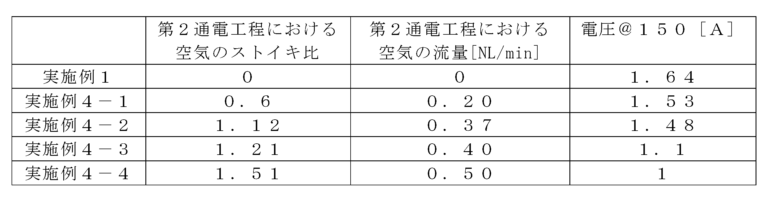
- Example 4 In Example 4, the activation time, the number of repetitions, and the interval time were the same as in Example 1, and the flow rate of air in the second energization process was changed as shown in Table 4 below.
- the air flow rate in the second energization step was 0.20 [NL/min]
- Example 4-2 the air flow rate in the second energization step was 0.37 [NL/min].
- Example 4-3 the flow rate of air in the second energization process was 0.40 [NL/min]
- Example 4-4 the flow rate of air in the second energization process was 0.50 [NL/min]. min].
- the flow rates of gases such as hydrogen gas and nitrogen gas other than the flow rate of air in the second energization step are the same as those in the first embodiment.
- the stoichiometric ratio of air in the second energization step is 0.6 in Example 4-1, 1.12 in Example 4-2, 1.21 in Example 4-3, and Example 4-4. Became 1.51.
- the stoichiometric ratio of the air in the second energization step means the ratio to the theoretical air flow rate required for performing normal power generation in the fuel cell stack 1 while supplying hydrogen gas to the anode gas flow channel 27. It refers to the ratio of the flow rate of air in the two energizing steps (flow rate of air in the second energizing step/theoretical air flow rate).
- the voltage of the fuel cell stack after activation is higher in the order of Example 4-4, Example 4-3, Example 4-2, Example 4-1, and Example 1. .. That is, in the activation method according to the present invention, as the flow rate of air in the second energizing step is decreased, in other words, the flow rate of air and nitrogen gas in the cathode side gas supplied to the cathode side gas passage 28 in the second energizing step. It can be said that the smaller the ratio (flow rate of air/flow rate of nitrogen gas), the more efficiently the activation can be performed in a shorter time. In particular, according to the results of Table 4 above, a large difference in the effect of activation is recognized between Example 4-2 and Example 4-3.
- the flow rate of the air supplied to the cathode side gas passage 28 in the second energization step is set to be smaller than the flow rate of the air supplied to the cathode side gas passage 28 in the first energization step, and the stoichiometric ratio is set to 1.12. It can be said that the following is preferable.
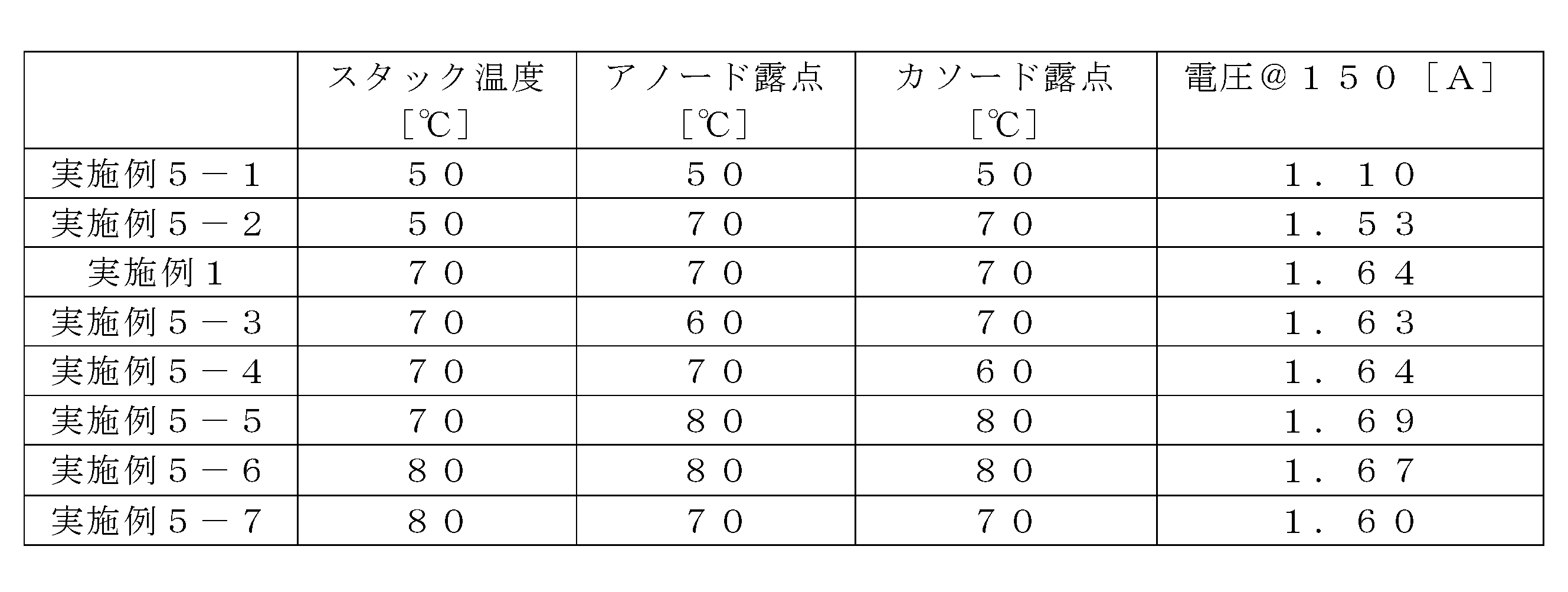
- Example 5 In Example 5, the activation time, the number of repetitions, the interval time, and the flow rates of various gases were the same as in Example 1, and the temperature of the fuel cell stack (stack temperature), the dew point of the anode gas (anode dew point), and the cathode were used.
- the combination of side gas dew points (cathode dew points) was changed as shown in Table 5 below.
- the stack temperature was 50[° C.]
- the anode dew point was 50[° C.]
- the cathode dew point was 50[° C.]
- Example 5-2 the stack temperature was 50[° C.], the anode dew point.
- Example 5-3 the stack temperature is 70[° C.], the anode dew point is 60[° C.], and the cathode dew point is 70[° C.].
- Example 5-4 the stack temperature was 70 [°C], the anode dew point was 70 [°C], and the cathode dew point was 60 [°C].
- Example 5-5 the stack temperature was 70 [°C] and the anode dewpoint was
- Example 5-6 the stack temperature was 80 [° C.], the anode dew point was 80 [° C.], and the cathode dew point was 80 [° C.].
- the stack temperature was 80 [° C.], the anode dew point was 70 [° C.], and the cathode dew point was 70 [° C.].
- Example 5-1 the voltage of the fuel cell stack after activation was determined as follows: Example 5-1, Example 5-2, Example 5-7, Example 5-3, Example 1, Example 5 -4, Example 5-6, and Example 5-5 in this order.
- Example 5-1 a large difference in the effect of activation is recognized between Example 5-1 and Example 5-2. Therefore, it can be said that it is preferable that the dew point of the anode gas is higher than 50 [°C] and the dew point of the cathode gas is higher than 50 [°C].
- the activation method of the present invention efficiently activates the fuel cell stack in a short time by adjusting the stack temperature, the anode dew point, and the cathode dew point according to the specifications of the fuel cell stack to be activated. it can.
- Fuel cell stack fuel cell
- Fuel cell fuel cell
- Fuel cell fuel cell
- Electrolyte membrane electrolyte layer
- Anode electrode 26
- Activation device 4 Anode side gas supply device 41
- Hydrogen gas supply source 42
- Hydrogen gas supply path 5
- Cathode side gas supply device 51 Air pump (oxidant gas supply source)
- Nitrogen gas supply source inert gas supply source
- Control device (switching means) 54
- Cathode side gas supply path cathode side gas supply path
- 6 External electrical load (external electrical load) 7
- Cell voltage sensor voltage sensor
Landscapes
- Life Sciences & Earth Sciences (AREA)
- Engineering & Computer Science (AREA)
- Manufacturing & Machinery (AREA)
- Sustainable Development (AREA)
- Sustainable Energy (AREA)
- Chemical & Material Sciences (AREA)
- Chemical Kinetics & Catalysis (AREA)
- Electrochemistry (AREA)
- General Chemical & Material Sciences (AREA)
- Fuel Cell (AREA)
Abstract
Description
始めにS1では、燃料電池スタック1のアノード電極25とカソード電極26とを外部電気負荷6によって電気的に接続する。次にS2では、温度調整装置8によって燃料電池スタック1の冷媒流路29へ所定の温度に調整した伝熱媒体を供給することにより、燃料電池スタック1を所定の温度に維持する。
(1)本実施形態に係る活性化方法では、アノード電極25に水素ガスを供給するとともにカソード電極26に空気を供給することにより両電極25,26の間に電位差を生じさせた状態で両電極25,26を、外部電気負荷6を介して電気的に接続し通電する第1通電工程と、アノード電極25に水素ガスを供給するとともにカソード電極26に窒素ガスを供給することにより両電極25,26の間に電位差を生じさせた状態で両電極を、外部電気負荷6を介して電気的に接続し通電する第2通電工程と、を実行することにより燃料電池スタック1を活性化する。これにより、本実施形態に係る活性化方法によれば、カソード電極26へ空気を断続的に供給する従来の活性化方法と比較して、燃料電池スタック1の劣化を抑制しながら短い時間で燃料電池スタック1を活性化できる。
実施例1では、上記10セルの燃料電池スタック1に活性化装置3を接続し、図2の活性化方法に基づいて第1通電工程と第2通電工程とを交互に繰り返し実行した。この際、燃料電池スタック1の温度は、温度調整装置8を用いて70℃に保った。また実施例1では、アノード側ガス供給装置4を用いることにより、露点が70℃となるように加湿した水素ガスをアノード側ガスとしてアノード側ガス流路27に供給した。ここで水素ガスの流量は0.3[NL/min]とした。また実施例1では、カソード側ガス供給装置5を用いることにより、露点が70℃となるように加湿した空気と窒素ガスとを混合したものをカソード側ガスとしてカソード側ガス流路28に供給した。ここで空気の流量は0.7[NL/min]とし、窒素ガスの流量は1.4[NL/min]とした。また実施例1では、上記のような流量で窒素ガスを供給し続けながら、1分毎に空気の供給をオンからオフ又はオフからオンに切り替えることにより、第1通電工程及び第2通電工程を1分間ずつ交互に、それぞれ30回ずつ実行した。すなわち実施例1の活性化にかかった時間は計1時間である。また第1及び第2通電工程では、上記のようにガスを供給しながら、両電極25,26間で2[A]の電流を引き続けた。このとき、アノード側ガス供給装置4及びカソード側ガス供給装置5は、第1通電工程及び第2通電工程を行っている間、アノード側ガス流路27とカソード側ガス流路28との間の圧力差が所定値で維持されるようにアノード側ガス及びカソード側ガスを供給した。
比較例1では、上記10セルの燃料電池スタック1に活性化装置3を接続し、図2の活性化方法のうち第1通電工程のみを実行した。この際、燃料電池スタック1の温度は、温度調整装置8を用いて70℃に保った。比較例1では、アノード側ガス供給装置4を用いることにより、露点が70℃となるように加湿した水素ガスをアノード側ガスとしてアノード側ガス流路27に供給した。また比較例1では、カソード側ガス供給装置5を用いることにより、露点が70℃となるように加湿した空気をカソード側ガスとしてカソード側ガス流路28に供給した。ここで水素ガスの流量は20[NL/min]とし、空気の流量は50[NL/min]とし、計1時間にわたり、両電極25,26間で150[A]の電流を引き続けた。以上のように、活性化を行った時間は、比較例1と実施例1とで同じであるが、水素ガスの使用量や電流は、実施例1よりも比較例1の方が大きい。また比較例1は、第2通電工程を含まない点において実施例1と異なる。
比較例2では、上記10セルの燃料電池スタック1に活性化装置3を接続し、図2の活性化方法のうち第1通電工程のみを実行した。この際、燃料電池スタック1の温度は、温度調整装置8を用いて70℃に保った。比較例2では、アノード側ガス供給装置4を用いることにより、露点が70℃となるように加湿した水素ガスをアノード側ガスとしてアノード側ガス流路27に供給した。また比較例2では、カソード側ガス供給装置5を用いることにより、露点が70℃となるように加湿した空気をカソード側ガスとしてカソード側ガス流路28に供給した。ここで水素ガスの流量は0.3[NL/min]とし、空気の流量は0.7[NL/min]とし、計1時間にわたり、両電極25,26間で2[A]の電流を引き続けた。以上のように活性化を行った時間、水素ガスの使用量、及び電流は、比較例2と実施例1とで同じである。また比較例2は、第2通電工程を含まない点において実施例1と異なる。
比較例3では、上記10セルの燃料電池スタック1に活性化装置3を接続し、特開2010-267455号公報に記載の活性化方法を再現した。この際、燃料電池スタック1の温度は、温度調整装置8を用いて70℃に保った。比較例3では、アノード側ガス供給装置4を用いることにより、露点が70℃となるように加湿した水素ガスをアノード側ガスとしてアノード側ガス流路27に供給した。ここで水素ガスの流量は0.3[NL/min]とした。また比較例3では、カソード側ガス供給装置5を用いることにより、露点が70℃となるように加湿した空気をカソード側ガスとしてカソード側ガス流路28に供給した。また比較例3では、1分毎に空気の供給をオンからオフ又はオフからオンに切り替えた。ここで空気の供給をオンにしている間における空気の流量は、0.7[NL/min]とした。また比較例3では、このように空気の供給をオンとする工程と空気の供給をオフとする工程とを、1分間ずつ交互に、それぞれ30回ずつ実行した。すなわち比較例3の活性化にかかった時間は計1時間である。また比較例3では、上記のようにガスを供給しながら、両電極25,26間で2[A]の電流を引き続けた。以上のように、活性化を行った時間、水素ガスの使用量、及び電流は、比較例3と実施例1とで同じである。また比較例3は、空気の供給をオフとしている間に窒素ガスを供給していない点において、実施例1と異なる。

実施例2では、活性化を行う時間を実施例1と同じ1時間とし、第1通電工程及び第2通電工程を交互に繰り返し行う回数(繰り返し回数)並びに第1通電工程又は第2通電工程を実行する時間(インターバル時間)を下記表2に記載のように変化させた。実施例2-1では、繰り返し回数を2[回]とし、インターバル時間を15[分]とし、実施例2-2では、繰り返し回数を5[回]とし、インターバル時間を5[分]とし、実施例2-3では、繰り返し回数を10[回]とし、インターバル時間を3[分]とし、実施例2-4では、繰り返し回数を60[回]とし、インターバル時間を0.5[分]とした。

実施例3では、第1通電工程又は第2通電工程を実行する時間(インターバル時間)を実施例1と同じ1[分]とし、活性化を行う時間並びに第1通電工程及び第2通電工程を交互に繰り返し行う回数(繰り返し回数)を下記表3のように変化させた。実施例3-1では、繰り返し回数を10[回]とし、活性化時間を1/3[時間]とし、実施例3-2では、繰り返し回数を20[回]とし、活性化時間を2/3[時間]とし、実施例3-3では、繰り返し回数を60[回]とし、活性化時間を2[時間]とし、実施例3-4では、繰り返し回数を90[回]とし、活性化時間を3[時間]とした。

実施例4では、活性化時間、繰り返し回数、及びインターバル時間を実施例1と同じとし、第2通電工程における空気の流量を下記表4のように変化させた。実施例4-1では、第2通電工程における空気の流量を0.20[NL/min]とし、実施例4-2では、第2通電工程における空気の流量を0.37[NL/min]とし、実施例4-3では、第2通電工程における空気の流量を0.40[NL/min]とし、実施例4-4では、第2通電工程における空気の流量を0.50[NL/min]とした。なお第2通電工程における空気の流量以外の水素ガスや窒素ガス等のガスの流量は、何れも実施例1と同じである。また第2通電工程における空気のストイキ比は、実施例4-1では0.6となり、実施例4-2では1.12となり、実施例4-3では1.21となり、実施例4-4では1.51となった。ここで第2通電工程における空気のストイキ比とは、アノード側ガス流路27に水素ガスを供給しながら燃料電池スタック1において通常の発電を行うために必要となる理論上の空気の流量に対する第2通電工程における空気の流量の比(第2通電工程における空気の流量/理論上の空気の流量)をいう。
実施例5では、活性化時間、繰り返し回数、インターバル時間、及び各種ガスの流量を実施例1と同じとし、燃料電池スタックの温度(スタック温度)、アノード側ガスの露点(アノード露点)、及びカソード側ガスの露点(カソード露点)の組み合わせを下記表5に記載のように変化させた。実施例5-1では、スタック温度を50[℃]、アノード露点を50[℃]、及びカソード露点を50[℃]とし、実施例5-2では、スタック温度を50[℃]、アノード露点を70[℃]、及びカソード露点を70[℃]とし、実施例5-3では、スタック温度を70[℃]、アノード露点を60[℃]、及びカソード露点を70[℃]とし、実施例5-4では、スタック温度を70[℃]、アノード露点を70[℃]、及びカソード露点を60[℃]とし、実施例5-5では、スタック温度を70[℃]、アノード露点を80[℃]、及びカソード露点を80[℃]とし、実施例5-6では、スタック温度を80[℃]、アノード露点を80[℃]、及びカソード露点を80[℃]とし、実施例5-7では、スタック温度を80[℃]、アノード露点を70[℃]、及びカソード露点を70[℃]とした。
2…燃料電池セル(燃料電池)
24…電解質膜(電解質層)
25…アノード電極
26…カソード電極
3…活性化装置
4…アノード側ガス供給装置
41…水素ガス供給源
42…水素ガス供給路(アノード側ガス供給路)
5…カソード側ガス供給装置
51…エアポンプ(酸化剤ガス供給源)
52…窒素ガス供給源(不活性ガス供給源)
53…制御装置(切替手段)
54…カソード側ガス供給路(カソード側ガス供給路)
6…外部電気負荷(外部電気負荷)
7…セル電圧センサ(電圧センサ)
Claims (6)
- 固体高分子を含む電解質層と、当該電解質層の一方の面に設けられたアノード電極と、前記電解質層の他方の面に設けられたカソード電極と、を備える燃料電池の活性化方法であって、
前記アノード電極にアノード側ガスとして水素ガスを供給するとともに前記カソード電極にカソード側ガスとして酸化剤ガスを供給することにより、前記アノード電極と前記カソード電極との間に電位差を生じさせた状態で、前記アノード電極と前記カソード電極とを外部電気負荷を介して電気的に接続し通電する第1通電工程と、
前記アノード電極にアノード側ガスとして水素ガスを供給するとともに前記カソード電極にカソード側ガスとして不活性ガスを供給することにより、前記アノード電極と前記カソード電極との間に電位差を生じさせた状態で、前記アノード電極と前記カソード電極とを前記外部電気負荷を介して電気的に接続し通電する第2通電工程と、を備えることを特徴とする燃料電池の活性化方法。 - 前記第1通電工程と前記第2通電工程とを交互に複数回繰り返し行うことを特徴とする請求項1に記載の燃料電池の活性化方法。
- 前記第1通電工程では、酸化剤ガスと不活性ガスとを混合したものをカソード側ガスとして前記カソード電極に供給し、
前記第1通電工程から前記第2通電工程に移行する際には、不活性ガスの供給を継続しながら酸化剤ガスの供給をオフにすることを特徴とする請求項1又は2に記載の燃料電池の活性化方法。 - 前記第2通電工程を行っている間に前記アノード電極と前記カソード電極との間の電位差が所定電圧以下である状態が所定時間継続した後に、前記第2通電工程から前記第1通電工程に移行することを特徴とする請求項1から3に記載の燃料電池の活性化方法。
- 固体高分子を含む電解質層と、当該電解質層の一方の面に設けられたアノード電極と、前記電解質層の他方の面に設けられたカソード電極と、を備える燃料電池の活性化装置であって、
前記アノード電極と前記カソード電極とを電気的に接続する外部電気負荷と、
水素ガスを供給する水素ガス供給源と、
前記アノード電極と前記水素ガス供給源とを接続するアノード側ガス供給路と、
酸化剤ガスを供給する酸化剤ガス供給源と、
不活性ガスを供給する不活性ガス供給源と、
前記カソード電極と前記酸化剤ガス供給源及び前記不活性ガス供給源とを接続するカソード側ガス供給路と、
前記酸化剤ガス供給源から前記カソード電極への酸化剤ガスの供給を交互にオン又はオフにする制御手段と、を備えることを特徴とする燃料電池の活性化装置。 - 前記アノード電極と前記カソード電極との間の電位差を検出する電圧センサをさらに備え、
前記制御手段は、前記酸化剤ガスの供給をオフにしているときに前記電位差が所定電圧以下に低下した状態が所定時間継続した後に、前記酸化剤ガスの供給をオンにすることを特徴とする請求項5に記載の燃料電池の活性化装置。
Priority Applications (3)
| Application Number | Priority Date | Filing Date | Title |
|---|---|---|---|
| JP2020562436A JP7080348B2 (ja) | 2018-12-26 | 2019-12-26 | 燃料電池の活性化方法及び活性化装置 |
| US17/417,103 US20220052362A1 (en) | 2018-12-26 | 2019-12-26 | Fuel cell activation method and apparatus |
| CN201980085392.7A CN113228360B (zh) | 2018-12-26 | 2019-12-26 | 燃料电池的活性化方法和活性化装置 |
Applications Claiming Priority (2)
| Application Number | Priority Date | Filing Date | Title |
|---|---|---|---|
| JP2018243307 | 2018-12-26 | ||
| JP2018-243307 | 2018-12-26 |
Publications (1)
| Publication Number | Publication Date |
|---|---|
| WO2020138338A1 true WO2020138338A1 (ja) | 2020-07-02 |
Family
ID=71129526
Family Applications (1)
| Application Number | Title | Priority Date | Filing Date |
|---|---|---|---|
| PCT/JP2019/051244 Ceased WO2020138338A1 (ja) | 2018-12-26 | 2019-12-26 | 燃料電池の活性化方法及び活性化装置 |
Country Status (4)
| Country | Link |
|---|---|
| US (1) | US20220052362A1 (ja) |
| JP (1) | JP7080348B2 (ja) |
| CN (1) | CN113228360B (ja) |
| WO (1) | WO2020138338A1 (ja) |
Cited By (2)
| Publication number | Priority date | Publication date | Assignee | Title |
|---|---|---|---|---|
| CN113178598A (zh) * | 2021-04-12 | 2021-07-27 | 武汉氢能与燃料电池产业技术研究院有限公司 | 一种氢氧燃料电池活化测试的辅助启停装置和启停方法 |
| JP2022143038A (ja) * | 2021-03-17 | 2022-10-03 | 本田技研工業株式会社 | 燃料電池の製造方法 |
Families Citing this family (2)
| Publication number | Priority date | Publication date | Assignee | Title |
|---|---|---|---|---|
| CN114284529B (zh) * | 2021-12-27 | 2024-07-16 | 深圳市贝特瑞新能源技术研究院有限公司 | 电池活化方法及电池活化装置 |
| CN115064732B (zh) * | 2022-07-25 | 2024-02-23 | 中汽创智科技有限公司 | 一种质子交换膜燃料电池的活化方法 |
Citations (3)
| Publication number | Priority date | Publication date | Assignee | Title |
|---|---|---|---|---|
| JP2004349050A (ja) * | 2003-05-21 | 2004-12-09 | Aisin Seiki Co Ltd | 固体高分子型燃料電池の賦活方法 |
| JP2005135857A (ja) * | 2003-10-31 | 2005-05-26 | Espec Corp | 燃料電池評価方法、および燃料電池評価装置 |
| JP2017079194A (ja) * | 2015-10-22 | 2017-04-27 | トヨタ自動車株式会社 | 固体高分子型燃料電池の活性化方法 |
Family Cites Families (2)
| Publication number | Priority date | Publication date | Assignee | Title |
|---|---|---|---|---|
| JP4613482B2 (ja) * | 2003-08-28 | 2011-01-19 | パナソニック株式会社 | 燃料電池発電装置とその運転方法 |
| KR100513541B1 (ko) * | 2003-11-27 | 2005-09-07 | 현대자동차주식회사 | 고체 고분자 연료 전지의 초기 활성화 방법 |
-
2019
- 2019-12-26 WO PCT/JP2019/051244 patent/WO2020138338A1/ja not_active Ceased
- 2019-12-26 JP JP2020562436A patent/JP7080348B2/ja active Active
- 2019-12-26 CN CN201980085392.7A patent/CN113228360B/zh active Active
- 2019-12-26 US US17/417,103 patent/US20220052362A1/en not_active Abandoned
Patent Citations (3)
| Publication number | Priority date | Publication date | Assignee | Title |
|---|---|---|---|---|
| JP2004349050A (ja) * | 2003-05-21 | 2004-12-09 | Aisin Seiki Co Ltd | 固体高分子型燃料電池の賦活方法 |
| JP2005135857A (ja) * | 2003-10-31 | 2005-05-26 | Espec Corp | 燃料電池評価方法、および燃料電池評価装置 |
| JP2017079194A (ja) * | 2015-10-22 | 2017-04-27 | トヨタ自動車株式会社 | 固体高分子型燃料電池の活性化方法 |
Cited By (3)
| Publication number | Priority date | Publication date | Assignee | Title |
|---|---|---|---|---|
| JP2022143038A (ja) * | 2021-03-17 | 2022-10-03 | 本田技研工業株式会社 | 燃料電池の製造方法 |
| JP7290682B2 (ja) | 2021-03-17 | 2023-06-13 | 本田技研工業株式会社 | 燃料電池の製造方法 |
| CN113178598A (zh) * | 2021-04-12 | 2021-07-27 | 武汉氢能与燃料电池产业技术研究院有限公司 | 一种氢氧燃料电池活化测试的辅助启停装置和启停方法 |
Also Published As
| Publication number | Publication date |
|---|---|
| CN113228360B (zh) | 2024-12-27 |
| CN113228360A (zh) | 2021-08-06 |
| US20220052362A1 (en) | 2022-02-17 |
| JP7080348B2 (ja) | 2022-06-03 |
| JPWO2020138338A1 (ja) | 2021-10-21 |
Similar Documents
| Publication | Publication Date | Title |
|---|---|---|
| JP5526226B2 (ja) | 固体高分子型燃料電池の活性化方法 | |
| KR101601378B1 (ko) | 연료 전지 관리 방법 | |
| JP7080348B2 (ja) | 燃料電池の活性化方法及び活性化装置 | |
| US8889308B2 (en) | Fuel cell system and driving method for the same | |
| JP2010282768A (ja) | 可逆セルの運転方法 | |
| JP2000113896A (ja) | 固体高分子型燃料電池およびそのシステム | |
| JP2011216483A (ja) | 燃料電池システムの駆動方法およびシステム | |
| JP2005032652A (ja) | 燃料電池システム | |
| CN103329324B (zh) | 固体高分子型燃料电池系统的运转方法以及固体高分子型燃料电池系统 | |
| CN100388546C (zh) | 燃料电池的运转方法 | |
| JP4727642B2 (ja) | 水素製造発電システムの運転方法 | |
| JP2007141744A (ja) | 燃料電池システム | |
| US10439241B2 (en) | Methods and processes to recover the voltage loss due to anode contamination | |
| JP2007005000A (ja) | 燃料電池システムの制御方法 | |
| JP2007294291A (ja) | 燃料電池システム | |
| JP2006202718A (ja) | 燃料電池システム | |
| JP5504726B2 (ja) | 燃料電池システム及び燃料電池の特性回復方法 | |
| JP5073448B2 (ja) | 固体高分子型燃料電池の運転方法 | |
| JP5073447B2 (ja) | 固体高分子型燃料電池の運転方法 | |
| JP2005268091A (ja) | 燃料電池の運転方法および燃料電池システム | |
| JP2007128790A (ja) | 燃料電池の制御方法及びその制御装置 | |
| JP2012009182A (ja) | 燃料電池システム、燃料電池の発電方法およびフラッディング判断方法 | |
| JP5154043B2 (ja) | 燃料電池システム | |
| JP2006190571A (ja) | 燃料電池の制御装置 | |
| US20110318664A1 (en) | Fuel cell system and driving method for the same |
Legal Events
| Date | Code | Title | Description |
|---|---|---|---|
| 121 | Ep: the epo has been informed by wipo that ep was designated in this application |
Ref document number: 19903582 Country of ref document: EP Kind code of ref document: A1 |
|
| ENP | Entry into the national phase |
Ref document number: 2020562436 Country of ref document: JP Kind code of ref document: A |
|
| NENP | Non-entry into the national phase |
Ref country code: DE |
|
| 122 | Ep: pct application non-entry in european phase |
Ref document number: 19903582 Country of ref document: EP Kind code of ref document: A1 |
|
| WWG | Wipo information: grant in national office |
Ref document number: 201980085392.7 Country of ref document: CN |