WO2020138216A1 - 固体電解質組成物、全固体二次電池用シート及び全固体二次電池、並びに、全固体二次電池用シート若しくは全固体二次電池の製造方法 - Google Patents
固体電解質組成物、全固体二次電池用シート及び全固体二次電池、並びに、全固体二次電池用シート若しくは全固体二次電池の製造方法 Download PDFInfo
- Publication number
- WO2020138216A1 WO2020138216A1 PCT/JP2019/050939 JP2019050939W WO2020138216A1 WO 2020138216 A1 WO2020138216 A1 WO 2020138216A1 JP 2019050939 W JP2019050939 W JP 2019050939W WO 2020138216 A1 WO2020138216 A1 WO 2020138216A1
- Authority
- WO
- WIPO (PCT)
- Prior art keywords
- solid electrolyte
- solid
- group
- active material
- secondary battery
- Prior art date
- Legal status (The legal status is an assumption and is not a legal conclusion. Google has not performed a legal analysis and makes no representation as to the accuracy of the status listed.)
- Ceased
Links
Images


Classifications
-
- H—ELECTRICITY
- H01—ELECTRIC ELEMENTS
- H01M—PROCESSES OR MEANS, e.g. BATTERIES, FOR THE DIRECT CONVERSION OF CHEMICAL ENERGY INTO ELECTRICAL ENERGY
- H01M10/00—Secondary cells; Manufacture thereof
- H01M10/05—Accumulators with non-aqueous electrolyte
- H01M10/056—Accumulators with non-aqueous electrolyte characterised by the materials used as electrolytes, e.g. mixed inorganic/organic electrolytes
- H01M10/0561—Accumulators with non-aqueous electrolyte characterised by the materials used as electrolytes, e.g. mixed inorganic/organic electrolytes the electrolyte being constituted of inorganic materials only
- H01M10/0562—Solid materials
-
- H—ELECTRICITY
- H01—ELECTRIC ELEMENTS
- H01B—CABLES; CONDUCTORS; INSULATORS; SELECTION OF MATERIALS FOR THEIR CONDUCTIVE, INSULATING OR DIELECTRIC PROPERTIES
- H01B1/00—Conductors or conductive bodies characterised by the conductive materials; Selection of materials as conductors
- H01B1/06—Conductors or conductive bodies characterised by the conductive materials; Selection of materials as conductors mainly consisting of other non-metallic substances
-
- H—ELECTRICITY
- H01—ELECTRIC ELEMENTS
- H01M—PROCESSES OR MEANS, e.g. BATTERIES, FOR THE DIRECT CONVERSION OF CHEMICAL ENERGY INTO ELECTRICAL ENERGY
- H01M10/00—Secondary cells; Manufacture thereof
- H01M10/05—Accumulators with non-aqueous electrolyte
- H01M10/058—Construction or manufacture
- H01M10/0585—Construction or manufacture of accumulators having only flat construction elements, i.e. flat positive electrodes, flat negative electrodes and flat separators
-
- H—ELECTRICITY
- H01—ELECTRIC ELEMENTS
- H01M—PROCESSES OR MEANS, e.g. BATTERIES, FOR THE DIRECT CONVERSION OF CHEMICAL ENERGY INTO ELECTRICAL ENERGY
- H01M4/00—Electrodes
- H01M4/02—Electrodes composed of, or comprising, active material
- H01M4/13—Electrodes for accumulators with non-aqueous electrolyte, e.g. for lithium-accumulators; Processes of manufacture thereof
- H01M4/139—Processes of manufacture
-
- H—ELECTRICITY
- H01—ELECTRIC ELEMENTS
- H01M—PROCESSES OR MEANS, e.g. BATTERIES, FOR THE DIRECT CONVERSION OF CHEMICAL ENERGY INTO ELECTRICAL ENERGY
- H01M4/00—Electrodes
- H01M4/02—Electrodes composed of, or comprising, active material
- H01M4/62—Selection of inactive substances as ingredients for active masses, e.g. binders, fillers
-
- H—ELECTRICITY
- H01—ELECTRIC ELEMENTS
- H01B—CABLES; CONDUCTORS; INSULATORS; SELECTION OF MATERIALS FOR THEIR CONDUCTIVE, INSULATING OR DIELECTRIC PROPERTIES
- H01B1/00—Conductors or conductive bodies characterised by the conductive materials; Selection of materials as conductors
- H01B1/06—Conductors or conductive bodies characterised by the conductive materials; Selection of materials as conductors mainly consisting of other non-metallic substances
- H01B1/10—Conductors or conductive bodies characterised by the conductive materials; Selection of materials as conductors mainly consisting of other non-metallic substances sulfides
-
- H—ELECTRICITY
- H01—ELECTRIC ELEMENTS
- H01M—PROCESSES OR MEANS, e.g. BATTERIES, FOR THE DIRECT CONVERSION OF CHEMICAL ENERGY INTO ELECTRICAL ENERGY
- H01M10/00—Secondary cells; Manufacture thereof
- H01M10/05—Accumulators with non-aqueous electrolyte
- H01M10/052—Li-accumulators
-
- H—ELECTRICITY
- H01—ELECTRIC ELEMENTS
- H01M—PROCESSES OR MEANS, e.g. BATTERIES, FOR THE DIRECT CONVERSION OF CHEMICAL ENERGY INTO ELECTRICAL ENERGY
- H01M2300/00—Electrolytes
- H01M2300/0017—Non-aqueous electrolytes
- H01M2300/0065—Solid electrolytes
- H01M2300/0068—Solid electrolytes inorganic
-
- H—ELECTRICITY
- H01—ELECTRIC ELEMENTS
- H01M—PROCESSES OR MEANS, e.g. BATTERIES, FOR THE DIRECT CONVERSION OF CHEMICAL ENERGY INTO ELECTRICAL ENERGY
- H01M4/00—Electrodes
- H01M4/02—Electrodes composed of, or comprising, active material
- H01M4/36—Selection of substances as active materials, active masses, active liquids
- H01M4/38—Selection of substances as active materials, active masses, active liquids of elements or alloys
- H01M4/386—Silicon or alloys based on silicon
-
- H—ELECTRICITY
- H01—ELECTRIC ELEMENTS
- H01M—PROCESSES OR MEANS, e.g. BATTERIES, FOR THE DIRECT CONVERSION OF CHEMICAL ENERGY INTO ELECTRICAL ENERGY
- H01M4/00—Electrodes
- H01M4/02—Electrodes composed of, or comprising, active material
- H01M4/36—Selection of substances as active materials, active masses, active liquids
- H01M4/48—Selection of substances as active materials, active masses, active liquids of inorganic oxides or hydroxides
- H01M4/483—Selection of substances as active materials, active masses, active liquids of inorganic oxides or hydroxides for non-aqueous cells
Definitions
- the present invention relates to a solid electrolyte composition, a sheet for an all-solid secondary battery and an all-solid secondary battery, and a method for manufacturing a sheet for an all-solid secondary battery or an all-solid secondary battery.
- a lithium-ion secondary battery is a storage battery that has a negative electrode, a positive electrode, and an electrolyte sandwiched between the negative electrode and the positive electrode, and can charge and discharge by moving lithium ions back and forth between both electrodes.
- an organic electrolytic solution has been used as an electrolyte in a lithium ion secondary battery.
- the organic electrolytic solution is liable to leak, and there is a risk of short circuit inside the battery due to overcharging or overdischarging, which may cause ignition. Therefore, further improvement in safety and reliability is required. Under these circumstances, an all-solid secondary battery using an inorganic solid electrolyte instead of the organic electrolyte has been receiving attention.
- the all-solid-state secondary battery has a solid negative electrode, electrolyte, and positive electrode, and can greatly improve the safety and reliability of a battery using an organic electrolytic solution.
- an inorganic solid electrolyte, an active material, a binder (binder) and the like are contained as materials for forming constituent layers such as a negative electrode active material layer, a solid electrolyte layer and a positive electrode active material layer.
- Materials have been proposed.
- a binder (polymer) (B) having a segment a having at least one kind of bond selected from the main chain and a functional group-containing hydrocarbon polymer segment having at least one kind selected from a specific functional group group Solid electrolyte compositions are described.
- the constituent layers (solid electrolyte layer or active material layer) of the all-solid secondary battery are usually formed of inorganic solid electrolyte, binder particles, and solid particles such as active material, so that the solid particles have sufficient interfacial contact. Instead, the interfacial resistance is increased (ionic conductivity is decreased).
- the binding property between solid particles is weak
- the constituent layers are chipped, cracked, cracked or peeled off. Occurs. Further, peeling between the constituent layer and the base material also occurs.
- the present invention is a solid electrolyte composition having excellent dispersibility, which enhances the binding properties between solid particles in the all-solid-state secondary battery sheet constituent layer, and the ionic conductivity of the all-solid secondary battery sheet.
- An object of the present invention is to provide a solid electrolyte composition that can be applied at a high level and can realize an all-solid secondary battery having excellent battery performance.
- this invention makes it a subject to provide the sheet for all-solid-state secondary batteries using the above-mentioned solid electrolyte composition, all-solid secondary batteries, and these manufacturing methods.
- the present inventors have introduced at least one bond of a urethane bond, a urea bond, an amide bond, an imide bond and an ester bond into the main chain of the polymer constituting the binder, and At least one end of the main chain is sealed with a group having a molecular weight of 150 or more represented by the general formula (1) described below to improve the cohesive force of the polymer, and the polymer is adsorbed on solid particles. It was found that the dispersibility of the solid electrolyte composition can be improved by.
- this solid electrolyte composition as a material for forming a constituent layer of an all-solid secondary battery, it is possible to form a constituent layer in which solid particles are firmly bound while suppressing the interfacial resistance between the solid particles. It has been found that excellent battery performance can be imparted to all-solid-state secondary batteries.
- the present invention has been completed through further studies based on these findings.
- X represents —O—, —NR a1 — or —S—.
- Y represents -CR a2 2 -, -NR a1 -, or -S-.
- R a1 represents a hydrogen atom, an alkyl group or an aryl group
- R a2 represents a hydrogen atom or a substituent.
- L 1 represents a hydrocarbon group.
- R 1 represents a hydrogen atom or a substituent.
- Y represents —CR a2 2 —
- R 1 represents a hydrogen atom.
- the content of the group represented by the general formula (1) is 0.1 to 10 mol% in the total 100 mol% of each constituent component of the main chain of the polymer and the group represented by the general formula (1).
- ⁇ 4> The solid electrolyte composition according to any one of ⁇ 1> to ⁇ 3>, wherein Y represents —S—, and R 1 represents a group represented by the following general formula (2).
- R 11 to R 13 represent a hydrogen atom, an alkyl group or an aryl group.
- R 14 represents a hydrogen atom or a substituent.
- A represents a hydrogen atom or a substituent.
- n represents an integer of 1 to 1000.
- ⁇ 5> The solid electrolyte according to any one of ⁇ 1> to ⁇ 4>, wherein the content of the (B) binder is 0.01 to 10% by mass based on all solid components contained in the solid electrolyte composition.
- Composition. ⁇ 6> (C) The solid electrolyte composition according to any one of ⁇ 1> to ⁇ 5>, which contains an active material.
- ⁇ 7> The solid electrolyte composition according to ⁇ 6>, wherein the (C) active material is a negative electrode active material containing Si as a constituent element.
- D The solid electrolyte composition according to any one of ⁇ 1> to ⁇ 7>, which contains a conductive auxiliary agent.
- An all-solid secondary battery comprising a positive electrode active material layer, a solid electrolyte layer, and a negative electrode active material layer in this order, At least one layer of the positive electrode active material layer, the negative electrode active material layer, and the solid electrolyte layer is a layer formed of the solid electrolyte composition according to any one of ⁇ 1> to ⁇ 11>.
- Secondary battery. ⁇ 14> A method for producing a sheet for an all-solid secondary battery, comprising a step of applying the solid electrolyte composition according to any one of ⁇ 1> to ⁇ 11>.
- ⁇ 15> A method for manufacturing an all-solid secondary battery, comprising a step of applying the solid electrolyte composition according to any one of ⁇ 1> to ⁇ 11>.
- the solid electrolyte composition of the present invention has excellent dispersibility. Further, the solid electrolyte composition of the present invention, a sheet for all-solid secondary battery excellent in binding property and ionic conductivity between solid particles in the constituent layers, and an all-solid secondary battery excellent in battery performance. Can be realized. Moreover, the sheet for all-solid secondary batteries of the present invention is excellent in the binding property between solid particles in the constituent layers and the ionic conductivity. Further, the all solid state secondary battery of the present invention has excellent battery performance.
- the method for manufacturing an all-solid secondary battery sheet and the method for manufacturing an all-solid secondary battery of the present invention can provide the above-mentioned all-solid secondary battery sheet and all-solid secondary battery.
- FIG. 1 is a vertical cross-sectional view schematically showing an all-solid secondary battery according to a preferred embodiment of the present invention.
- FIG. 2 is a vertical cross-sectional view schematically showing the ion conductivity measuring test body produced in the example.
- the numerical range represented by “to” means a range including the numerical values before and after “to” as the lower limit value and the upper limit value.
- acrylic or “(meth)acrylic
- it means acrylic and/or methacrylic.
- acryloyl or “(meth)acryloyl”
- methacryloyl it means acryloyl and/or methacryloyl.
- the expression of a compound is used to mean the compound itself, a salt thereof, and an ion thereof.
- this carbon number means the carbon number of the entire group. That is, when this group is in the form of further having a substituent, it means the total number of carbon atoms including this substituent.
- substituents when there are a plurality of substituents, linking groups, etc. (hereinafter referred to as substituents) indicated by a specific symbol, or when a plurality of substituents, etc. are specified simultaneously or alternatively, It means that the substituents and the like may be the same as or different from each other. Further, even when not otherwise specified, when a plurality of substituents and the like are adjacent to each other, they may be linked to each other or condensed to form a ring.
- the mass average molecular weight (Mw) and the number average molecular weight (Mn) can be measured as a polystyrene-equivalent molecular weight by gel permeation chromatography (GPC) unless otherwise specified.
- GPC gel permeation chromatography
- a GPC device “HLC-8220” (trade name, manufactured by Tosoh Corporation) was used, G3000HXL+G2000HXL (both are trade names, manufactured by Tosoh Corporation) as a column, and a differential refraction at a measurement temperature of 23° C. and a flow rate of 1 mL/min. It shall be detected by a meter (RI detector).
- the eluent can be selected from THF (tetrahydrofuran), chloroform, NMP (N-methyl-2-pyrrolidone), and m-cresol/chloroform mixed solution (manufactured by Shonan Wako Pure Chemical Industries, Ltd.). If the measurement sample dissolves, THF will be used.
- Solid electrolyte composition The solid electrolyte composition of the present invention is also referred to as (A) an inorganic solid electrolyte having conductivity of ions of a metal belonging to Group 1 or 2 of the periodic table (hereinafter, also referred to as “(A) inorganic solid electrolyte”. ) And (B) binder.
- the solid electrolyte composition of the present invention when in a form containing (E) a dispersion medium (preferably a slurry), (B) the polarity of the polymer main chain constituting the binder is By having a large bond (at least one bond of a urethane bond, a urea bond, an amide bond, an imide bond, and an ester bond), the hydrogen bond between the bonds causes the cohesive force of the polymer in the solid electrolyte composition. It is expected to increase.
- at least one terminal of the polymer main chain is capped with a group having a molecular weight of 150 or more (terminal blocking group) represented by the general formula (1) described below, whereby the (B) binder is used.
- the dispersibility of the slurry can be improved by suppressing the aggregation of the.
- the solid electrolyte composition of the present invention contains (C) an active material, (D) a conductive auxiliary agent and the like in addition to (A) an inorganic solid electrolyte, it is considered that the dispersion stability can be similarly enhanced.
- the sheet for an all-solid-state secondary battery of the present invention and the all-solid secondary battery of the present invention have a (B) binder in the constituent layer.
- the inorganic solid electrolyte is an inorganic solid electrolyte, and the solid electrolyte is a solid electrolyte in which ions can move. Since it does not contain an organic substance as a main ion conductive material, it is an organic solid electrolyte (a polymer electrolyte typified by polyethylene oxide (PEO) or the like, an organic typified by lithium bis(trifluoromethanesulfonyl)imide (LiTFSI) or the like. Electrolyte salt) is clearly distinguished. Further, since the inorganic solid electrolyte is solid in the steady state, it is not usually dissociated or released into cations and anions.
- PEO polyethylene oxide
- LiTFSI lithium bis(trifluoromethanesulfonyl)imide
- the electrolytic solution or the inorganic electrolyte salt LiPF 6 , LiBF 4 , LiFSI, LiCl, etc.
- the inorganic solid electrolyte is not particularly limited as long as it has ion conductivity of a metal belonging to Group 1 or 2 of the periodic table, and generally has no electron conductivity.
- the inorganic solid electrolyte has ionic conductivity of a metal belonging to Group 1 or 2 of the periodic table.
- the inorganic solid electrolyte preferably has ionic conductivity of lithium ions.
- a solid electrolyte material applied to this type of product can be appropriately selected and used.
- the inorganic solid electrolyte examples include (i) sulfide-based inorganic solid electrolyte, (ii) oxide-based inorganic solid electrolyte, (iii) halide-based inorganic solid electrolyte, and (iV) hydride-based solid electrolyte.
- a sulfide-based inorganic solid electrolyte is preferably used because a good interface can be formed between the active material and the inorganic solid electrolyte.
- the sulfide-based inorganic solid electrolyte contains a sulfur atom (S), has ion conductivity of a metal belonging to Group 1 or 2 of the periodic table, and has electronic insulation. ..
- the sulfide-based inorganic solid electrolyte preferably contains at least Li, S and P as elements and has lithium ion conductivity, but other than Li, S and P depending on the purpose or case. It may contain an element.
- the sulfide-based inorganic solid electrolyte preferably has an ionic conductivity of 1 ⁇ 10 ⁇ 6 S/cm or more, more preferably 5 ⁇ 10 ⁇ 6 S/cm or more, and 1 ⁇ 10 ⁇ 5 S. /Cm or more is particularly preferable.
- the upper limit is not particularly limited, and is practically 1 ⁇ 10 ⁇ 1 S/cm or less.
- Examples of the sulfide-based inorganic solid electrolyte include a lithium ion conductive inorganic solid electrolyte satisfying the composition represented by the following formula (I).
- L represents an element selected from Li, Na and K, and Li is preferable.
- M represents an element selected from B, Zn, Sn, Si, Cu, Ga, Sb, Al and Ge.
- A represents an element selected from I, Br, Cl and F.
- a1 to e1 represent composition ratios of the respective elements, and a1:b1:c1:d1:e1 satisfies 1 to 12:0 to 5:1:2 to 12:0 to 10.
- a1 is preferably 1 to 9, and more preferably 1.5 to 7.5.
- b1 is preferably 0 to 3.
- d1 is preferably 2.5 to 10, and more preferably 3.0 to 8.5.
- e1 is preferably 0 to 5, and more preferably 0 to 3.
- composition ratio of each element can be controlled by adjusting the compounding amount of the raw material compound when producing the sulfide-based inorganic solid electrolyte as described below.
- the sulfide-based inorganic solid electrolyte may be amorphous (glass) or crystallized (glass-ceramic), or only a part thereof may be crystallized.
- glass glass
- glass-ceramic glass-ceramic
- Li—P—S based glass containing Li, P and S, or Li—P—S based glass ceramics containing Li, P and S can be used.
- the sulfide-based inorganic solid electrolyte is, for example, lithium sulfide (Li 2 S), phosphorus sulfide (eg, phosphorus pentasulfide (P 2 S 5 )), elemental phosphorus, elemental sulfur, sodium sulfide, hydrogen sulfide, lithium halide (eg, LiI, LiBr, LiCl) and a sulfide of the element represented by M (for example, SiS 2 , SnS, GeS 2 ) can be produced by a reaction of at least two raw materials.
- Li 2 S lithium sulfide
- phosphorus sulfide eg, phosphorus pentasulfide (P 2 S 5 )
- elemental phosphorus elemental sulfur
- sodium sulfide sodium sulfide
- hydrogen sulfide lithium halide
- a sulfide of the element represented by M for example, SiS 2 , S
- the ratio of Li 2 S and P 2 S 5 is, Li 2 S: at a molar ratio of P 2 S 5, preferably 60: 40 ⁇ 90:10, more preferably 68:32 to 78:22.
- the lithium ion conductivity can be increased.
- the lithium ion conductivity can be preferably 1 ⁇ 10 ⁇ 4 S/cm or more, more preferably 1 ⁇ 10 ⁇ 3 S/cm or more.
- the upper limit is not particularly limited, and is practically 1 ⁇ 10 ⁇ 1 S/cm or less.
- Li 2 S-P 2 S 5 Li 2 S-P 2 S 5 -LiCl, Li 2 S-P 2 S 5 -H 2 S, Li 2 S-P 2 S 5 -H 2 S-LiCl, Li 2 S-LiI-P 2 S 5 , Li 2 S-LiI-Li 2 O-P 2 S 5 , Li 2 S-LiBr-P 2 S 5 , Li 2 S-Li 2 O-P 2 S 5 , Li 2 S-Li 3 PO 4 -P 2 S 5 , Li 2 S-P 2 S 5 -P 2 O 5 , Li 2 S-P 2 S 5 -SiS 2 , Li 2 S-P 2 S 5 -SiS 2- LiCl, Li 2 S-P 2 S 5 -SnS, Li 2 S-P 2 S 5 -Al 2 S 3 , Li 2 S-
- amorphization method examples include a mechanical milling method, a solution method and a melt quenching method. This is because processing at room temperature is possible and the manufacturing process can be simplified.
- the oxide-based inorganic solid electrolyte is preferably a compound containing an oxygen atom (O), having the ion conductivity of a metal belonging to Group 1 or 2 of the periodic table, and having an electronic insulating property. ..
- the ionic conductivity of the oxide-based inorganic solid electrolyte is preferably 1 ⁇ 10 ⁇ 6 S/cm or more, more preferably 5 ⁇ 10 ⁇ 6 S/cm or more, and 1 ⁇ 10 ⁇ 5 S. /Cm or more is particularly preferable.
- the upper limit is not particularly limited, and is practically 1 ⁇ 10 ⁇ 1 S/cm or less.
- M bb is at least one element of Al, Mg, Ca, Sr, V, Nb, Ta, Ti, Ge, In, Sn, xb satisfies 5 ⁇ xb ⁇ 10, and yb satisfies 1 ⁇ yb ⁇ 4, zb satisfies 1 ⁇ zb ⁇ 4, mb satisfies 0 ⁇ mb ⁇ 2, and nb satisfies 5 ⁇ nb ⁇ 20.), Li xc Byc M cc zc O nc (M cc is At least one element selected from the group consisting of C, S, Al, Si, Ga, Ge, In, and Sn, xc satisfies 0 ⁇ xc ⁇ 5, yc satisfies 0 ⁇ yc ⁇ 1, and zc satisfies 0 ⁇ zc ⁇ 1 and nc satisfies 0 ⁇ nc ⁇ 6), Li xd (Al, Ga) yd (Ti, Ge) zd Si), Li
- Li 1+xh+yh (Al, Ga) xh (Ti, Ge) 2-xh Si yh P 3-yh O 12 (where 0 ⁇ xh ⁇ 1, 0 ⁇ yh ⁇ 1), Li having a garnet type crystal structure 7 La 3 Zr 2 O 12 (LLZ) and the like can be mentioned.
- a phosphorus compound containing Li, P and O is also desirable.
- lithium phosphate (Li 3 PO 4 ), LiPON and LiPOD 1 (D 1 is Ti, V, Cr, Mn, Fe, Co, Ni, Cu, Zr) in which a part of oxygen of lithium phosphate is replaced with nitrogen. , Nb, Mo, Ru, Ag, Ta, W, Pt, Au, etc.).
- LiA 1 ON (A 1 is at least one selected from Si, B, Ge, Al, C, Ga, etc.) and the like can also be preferably used.
- the halide-based inorganic solid electrolyte is preferably a compound containing a halogen atom, having ionic conductivity of a metal belonging to Group 1 or Group 2 of the periodic table, and having electronic insulation.
- the halide-based inorganic solid electrolyte is not particularly limited, and examples thereof include compounds such as LiCl, LiBr, LiI, Li 3 YBr 6 and Li 3 YCl 6 described in ADVANCED MATERIALS, 2018, 30, 1803075. Of these, Li 3 YBr 6 and Li 3 YCl 6 are preferable.
- the hydride-based inorganic solid electrolyte is preferably a compound containing a hydrogen atom, having the ion conductivity of a metal belonging to Group 1 or 2 of the periodic table, and having an electronic insulating property.
- the hydride-based inorganic solid electrolyte is not particularly limited, and examples thereof include LiBH 4 , Li 4 (BH 4 ) 3 I, 3LiBH 4 —LiCl, and the like.
- the inorganic solid electrolyte is preferably particles.
- the volume average particle size of the particulate inorganic solid electrolyte is not particularly limited and is preferably 0.01 ⁇ m or more, more preferably 0.1 ⁇ m or more.
- the upper limit is preferably 100 ⁇ m or less, and more preferably 50 ⁇ m or less.
- the average particle size of the inorganic solid electrolyte particles is measured by the following procedure.
- the inorganic solid electrolyte particles are diluted with water (heptane in the case of a substance which is unstable to water) to a dispersion of 1% by mass in a 20 ml sample bottle.
- the diluted dispersion sample is irradiated with ultrasonic waves of 1 kHz for 10 minutes, and immediately thereafter, used for the test.
- a laser diffraction/scattering particle size distribution analyzer LA-920 manufactured by HORIBA was used, and data was captured 50 times using a measuring quartz cell at a temperature of 25° C. to obtain volume average particles. Get the diameter.
- JISZ8828:2013 “Particle size analysis-dynamic light scattering method” as necessary. Five samples are prepared for each level, and the average value is adopted.
- the above inorganic solid electrolytes may be used alone or in combination of two or more.
- the content of the inorganic solid electrolyte in the solid component in the solid electrolyte composition is 100% by mass of the solid component when considering reduction of the interfacial resistance when used in an all-solid secondary battery and maintenance of the reduced interfacial resistance.
- the content is preferably 5% by mass or more, more preferably 10% by mass or more, further preferably 20% by mass or more, and further preferably 30% by mass or more.
- the upper limit is preferably 99.9% by mass or less, more preferably 99.5% by mass or less, and particularly preferably 99% by mass or less.
- the content of the inorganic solid electrolyte in the solid electrolyte composition is preferably such that the total content of the active material and the inorganic solid electrolyte is in the above range.
- the solid component means a component which does not volatilize or evaporate and disappear when subjected to a drying treatment at 170° C. for 6 hours under a nitrogen atmosphere. Typically, it refers to components other than the dispersion medium described below.
- the (B) binder contained in the solid electrolyte composition of the present invention contains a binder made of the following polymer.
- This polymer has a main chain containing at least one bond of urethane bond, urea bond, amide bond, imide bond and ester bond. Further, this polymer has a group represented by the following general formula (1) having a molecular weight of 150 or more (hereinafter, also referred to as “terminal blocking group”) on at least one terminal of the main chain.
- the main chain of a polymer means a linear molecular chain in which all the other molecular chains constituting the polymer can be regarded as branched chains or pendants with respect to the main chain.
- the longest chain among the molecular chains constituting the polymer becomes the main chain.
- the end capping group at the polymer end is not included in the main chain.
- the side chain of the polymer means a molecular chain other than the main chain, and includes a short molecular chain and a long molecular chain.
- the main chain of the polymer has at least one bond of urethane bond, urea bond, amide bond, imide bond and ester bond.
- these bonds contained in the main chain contribute to improving the binding property of the solid particles in the sheet for all-solid-state secondary battery or the constituent layers of the all-solid secondary battery as described above. Therefore, the hydrogen bond formed by these bonds may be the above bonds, or may be a partial structure other than the above bonds and the main chain. It is preferable that the above-mentioned bond has hydrogen atoms forming a hydrogen bond (the nitrogen atom of each bond is unsubstituted) from the viewpoint that hydrogen bonds can be formed with each other.
- the bond is not particularly limited as long as it is contained in the main chain of the polymer, and may be contained in the structural unit (repeating unit) and/or contained as a bond connecting different structural units. .. Moreover, the number of the above-mentioned bonds contained in the main chain is not limited to one and may be two or more. In this case, the bonding mode of the main chain is not particularly limited, and may have two or more kinds of bonds randomly, or even a main chain composed of a segment having a specific bond and a segment having another bond. Good.
- the main chain having the above-mentioned bond is not particularly limited, and a main chain having at least one segment of a urethane bond, a urea bond, an amide bond, an imide bond and an ester bond is preferable, and a chain composed of polyamide, polyurea or polyurethane. Is preferably contained in the main chain, and a main chain made of polyamide, polyurea or polyurethane is more preferable. Further, it is preferable that the main chain has a chain made of polyurethane, and the main chain made of polyurethane is more preferable.
- the main chain having the above-mentioned bond has a constitutional component represented by any one of the following formulas (I-1) to (I-4) (a constitutional component derived from a monomer) and a formula (I-5). And a combination of two or more (preferably 2 to 8 types, more preferably 2 to 4 types, further preferably 3 or 4 types) of constituent components derived from the compound (monomer) represented by any one of (I-6) Preferred backbones are The combination of each component is appropriately selected according to the above-mentioned binding.
- the urethane bond bonds the constituent component represented by formula (I-1) and the constituent component represented by formula (I-3). Due to the urea bond, the constituent component represented by the formula (I-1) and the constituent component represented by the formula (I-4) are bonded. By the amide bond, the constituent component represented by the formula (I-2) and the constituent component represented by the formula (I-4) are bonded. By the imide bond, the component derived from the compound represented by formula (I-5) and the component derived from the compound represented by formula (I-6) are bonded. The ester bond bonds the constituent component represented by formula (I-2) and the constituent component represented by formula (I-3).
- R P1 and R P2 each represent a molecular chain having a molecular weight or a mass average molecular weight of 20 or more and 200,000 or less.
- the molecular chain that can be taken as R P1 and R P2 is not particularly limited, and is preferably a hydrocarbon chain, polyalkylene oxide chain, polycarbonate chain or polyester chain, more preferably a hydrocarbon chain or polyalkylene oxide chain.
- the hydrocarbon chain which can be taken as R P1 and R P2 means a hydrocarbon chain composed of a carbon atom and a hydrogen atom, and more specifically, at least two compounds of a compound composed of a carbon atom and a hydrogen atom. It means a structure in which an atom (for example, a hydrogen atom) or a group (for example, a methyl group) is eliminated. End-capping groups that may be present at the ends of the hydrocarbon chain are not included in the hydrocarbon chain.
- This hydrocarbon chain may have a carbon-carbon unsaturated bond and may have a ring structure of an aliphatic ring and/or an aromatic ring. That is, the hydrocarbon chain may be a hydrocarbon chain composed of a hydrocarbon selected from an aliphatic hydrocarbon and an aromatic hydrocarbon.
- Such a hydrocarbon chain may be one that satisfies the above-mentioned molecular weight, and both a hydrocarbon chain having a low molecular weight and a hydrocarbon chain having a hydrocarbon polymer (also referred to as a hydrocarbon polymer chain).
- the low molecular weight hydrocarbon chain is a chain composed of a normal (specifically polymerizable) hydrocarbon group, and examples of this hydrocarbon group include an aliphatic or aromatic hydrocarbon group. Is an alkylene group (having preferably 1 to 12 carbon atoms, more preferably 1 to 6 and still more preferably 1 to 3), an arylene group (having 6 to 22 carbon atoms, preferably 6 to 14 and 6 to 10).
- the hydrocarbon group forming a low molecular weight hydrocarbon chain that can be taken as R P2 is more preferably an alkylene group, further preferably an alkylene group having 2 to 6 carbon atoms, and particularly preferably an alkylene group having 2 or 3 carbon atoms.
- the aliphatic hydrocarbon group is not particularly limited, and is a hydrogen reducing product of an aromatic hydrocarbon group represented by the following formula (M2), a partial structure of a known aliphatic diisosonate compound (for example, a group consisting of isophorone ) And the like.
- the aromatic hydrocarbon group is preferably a phenylene group or a hydrocarbon group represented by the following formula (M2).
- X represents a single bond, —CH 2 —, —C(CH 3 ) 2 —, —SO 2 —, —S—, —CO— or —O—, and is a binding point of view.
- —CH 2 — or —O— is preferable, and —CH 2 — is more preferable.
- the alkylene group exemplified here may be substituted with a halogen atom (preferably a fluorine atom).
- R M2 to R M5 each represent a hydrogen atom or a substituent, and a hydrogen atom is preferable.
- the substituent which can be taken as R M2 to R M5 is not particularly limited, and examples thereof include an alkyl group having 1 to 20 carbon atoms, an alkenyl group having 1 to 20 carbon atoms, —OR M6 , —N(R M6 ) 2 , —SR M6 (R M6 represents a substituent, preferably an alkyl group having 1 to 20 carbon atoms or an aryl group having 6 to 10 carbon atoms), halogen atom (eg, fluorine atom, chlorine atom, bromine atom) Is mentioned.
- R M6 represents a substituent, preferably an alkyl group having 1 to 20 carbon atoms or an aryl group having 6 to 10 carbon atoms
- halogen atom eg, fluorine atom, chlorine atom, bromine atom
- —N(R M6 ) 2 is an alkylamino group (having preferably 1 to 20 carbon atoms, more preferably 1 to 6) or an arylamino group (having 6 to 40 carbon atoms, preferably 6 to 20 carbon atoms). More preferred).
- the hydrocarbon polymer chain may be a polymer chain formed by polymerizing (at least two) polymerizable hydrocarbons, and a chain composed of a hydrocarbon polymer having a larger number of carbon atoms than the above-mentioned low molecular weight hydrocarbon chain.
- a chain composed of a hydrocarbon polymer composed of 30 or more, more preferably 50 or more carbon atoms is preferably a chain composed of a hydrocarbon polymer composed of 30 or more, more preferably 50 or more carbon atoms.
- the upper limit of the number of carbon atoms constituting the hydrocarbon polymer is not particularly limited and may be, for example, 3,000.
- This hydrocarbon polymer chain is preferably a chain composed of a hydrocarbon polymer whose main chain satisfies the above-mentioned number of carbon atoms and which is composed of an aliphatic hydrocarbon, and is composed of an aliphatic saturated hydrocarbon or an aliphatic unsaturated hydrocarbon. It is more preferable that the chain is a polymer (preferably elastomer) chain. Specific examples of the polymer include a diene polymer having a double bond in the main chain and a non-diene polymer having no double bond in the main chain.
- diene polymer examples include a styrene-butadiene copolymer, a styrene-ethylene-butadiene copolymer, a copolymer of isobutylene and isoprene (preferably butyl rubber (IIR)), a butadiene polymer, an isoprene polymer and ethylene.
- IIR butyl rubber
- non-diene polymer examples include olefin polymers such as ethylene-propylene copolymer and styrene-ethylene-butylene copolymer, and hydrogen reduction products of the above diene polymers.
- the hydrocarbon that becomes the hydrocarbon chain preferably has a reactive group at its terminal, and more preferably has a polycondensable terminal reactive group.
- the terminal reactive group capable of polycondensation or polyaddition forms a group bonded to R P1 to R P3 in the above formulas by polycondensation or polyaddition.
- Examples of such a terminal reactive group include an isocyanate group, a hydroxy group, a carboxy group, an amino group and an acid anhydride, and of these, a hydroxy group is preferable.
- hydrocarbon polymer having a terminal reactive group examples are, under the trade names, NISSO-PB series (manufactured by Nippon Soda Co., Ltd.), Claysol series (manufactured by Tomoe Kogyo Co., Ltd.), PolyVEST-HT series (manufactured by Evonik). , Poly-bd series (manufactured by Idemitsu Kosan Co., Ltd.), poly-ip series (manufactured by Idemitsu Kosan Co., Ltd.), EPOL (manufactured by Idemitsu Kosan Co., Ltd.) and Polytail series (manufactured by Mitsubishi Chemical Co., Ltd.) are preferably used.
- R P1 is preferably a low molecular weight hydrocarbon chain, and more preferably a hydrocarbon chain composed of an aromatic hydrocarbon group.
- R P2 is preferably a molecular chain other than a low molecular weight hydrocarbon chain or an aliphatic hydrocarbon group, and more preferably an embodiment containing a molecular chain other than a low molecular weight hydrocarbon chain and an aliphatic hydrocarbon group, respectively.
- R P2 in the component derived from the compound represented by any of the formula (I-3), the formula (I-4) and the formula (I-6), R P2 is an aliphatic hydrocarbon group. It is preferable to include at least two kinds of constituent components and constituent components in which R P2 is a molecular chain other than a low molecular weight hydrocarbon chain.
- the number of carbon atoms of the alkyleneoxy group in the polyalkylene oxide chain is preferably 1 to 10, more preferably 1 to 6, and 2 or 3 (polyethylene oxide chain or Polypropylene oxide chains) are more preferred.
- the polyalkylene oxide chain may be a chain composed of one kind of alkylene oxide or a chain composed of two or more kinds of alkylene oxide (for example, a chain composed of ethylene oxide and propylene oxide).
- Examples of the polycarbonate chain or polyester chain include known chains of polycarbonate or polyester.
- Each of the polyalkylene oxide chain, the polycarbonate chain and the polyester chain preferably has an alkyl group (having 1 to 12 carbon atoms, more preferably 1 to 6 carbon atoms) at the terminal.
- the molecular weight or mass average molecular weight of the molecular chain is preferably 30 or more, more preferably 50 or more, further preferably 100 or more, and particularly preferably 150 or more.
- the upper limit is preferably 100,000 or less, more preferably 10,000 or less.
- the molecular weight or mass average molecular weight of a molecular chain is measured for a raw material compound before being incorporated in the main chain of a polymer.
- R P3 represents an aromatic or aliphatic linking group (tetravalent), and a linking group represented by any of the following formulas (i) to (ix) is preferable.
- X 1 represents a single bond or a divalent linking group.
- the divalent linking group is preferably an alkylene group having 1 to 6 carbon atoms (eg methylene, ethylene, propylene). As propylene, 1,3-hexafluoro-2,2-propanediyl is preferable.
- L represents —CH 2 ⁇ CH 2 — or —CH 2 —.
- R X and R Y each represent a hydrogen atom or a substituent.
- * represents a binding site to the carbonyl group in formula (1-5).
- the substituent that can be used as R X and R Y is not particularly limited, and examples thereof include the substituent T described later.
- alkyl group having 1 to 12 carbon atoms, preferably 1 to 6 carbon atoms, more preferably 1 to 3 carbon atoms
- an aryl group having 6 to 22 carbon atoms, more preferably 6 to 14 carbon atoms, further preferably 6 to 10 carbon atoms
- 6 to 22 carbon atoms having 6 to 22 carbon atoms, more preferably 6 to 14 carbon atoms, further preferably 6 to 10 carbon atoms
- R b1 to R b4 represent a hydrogen atom or a substituent, and preferably a hydrogen atom. Examples of this substituent include the substituent T described later, and an alkyl group is preferable.
- the polymer constituting the binder has a structure in which R P2 is an aliphatic hydrocarbon group (preferably an ether) as a constituent component represented by formula (I-3) or formula (I-4), preferably formula (I-3). Group or a carbonyl group or both, more preferably a group having a carboxy group), and R P2 preferably has a component which is the above polyalkylene oxide chain as a molecular chain, and further R More preferably, P2 has, as a molecular chain, at least three kinds of constituent components which are the above-mentioned hydrocarbon polymer chains.
- R P2 is an aliphatic hydrocarbon group (preferably an ether) as a constituent component represented by formula (I-3) or formula (I-4), preferably formula (I-3).
- R P2 preferably has a component which is the above polyalkylene oxide chain as a molecular chain, and further R More
- the polymer constituting the binder has a constituent component represented by the following formula (I-1), a constituent component represented by the formula (I-3A) and a constituent component represented by the formula (I-3B). It is preferable that, in addition to these constitutional components, it further has a constitutional component represented by formula (I-3C).
- R P1 is as described above.
- R P2A represents an aliphatic hydrocarbon group, and preferably has an ether group or a carbonyl group, or both, and more preferably a carboxy group. Examples include bis(hydroxymethyl)acetic acid compounds such as 2,2-bis(hydroxymethyl)butyric acid.
- R P2B represents a polyalkylene oxide chain.
- R P2C represents a hydrocarbon polymer chain.
- the aliphatic hydrocarbon group that can be taken as R P2A , the polyalkylene oxide chain that can be taken as R P2B , and the hydrocarbon polymer chain that can be taken as R P2C are each an aliphatic that can be taken as R P2 in the above formula (I-3).
- the contents of the constituent components represented by the above formulas in the polymer forming the binder will be described later.
- the polymer constituting the binder may have a constituent component other than the constituent components represented by the above formulas, in addition to the terminal blocking group described below.
- Such constituents are not particularly limited as long as they can be sequentially polymerized with the raw material compounds leading to the constituents represented by the above formulas.
- the polymer constituting the binder has at least one terminal of the main chain of the polymer sealed with a group having a molecular weight of 150 or more (terminal blocking group) represented by the following general formula (1). There is. When the group contains a polymer, the molecular weight indicates the number average molecular weight.
- * represents a bonding part of the above-mentioned terminal blocking group to the polymer main chain.
- X represents —O—, —NR a1 — or —S—.
- Y represents -CR a2 2 -, -NR a1 -, or -S-.
- R a1 represents a hydrogen atom, an alkyl group or an aryl group
- R a2 represents a hydrogen atom or a substituent.
- L 1 represents a hydrocarbon group.
- R 1 represents a hydrogen atom or a substituent.
- Y represents —CR a2 2 —
- R 1 represents a hydrogen atom.
- X is preferably -O-
- Y is preferably -NR a1 -or -S-, and more preferably -S-.
- R a1 is preferably a hydrogen atom.
- Examples of the alkyl group and aryl group represented by R a1 include the alkyl group and aryl group described as the substituent T described later.
- R a2 is preferably a hydrogen atom.
- Examples of the substituent represented by R a2 include the substituent T described below.
- X, L 1 , Y and R 1 are applied in this order from the constituent component side of the group bonded to the constituent component of the main chain.
- the terminal blocking group is different from the constituent component that constitutes the polymer main chain that constitutes the (B) binder.
- the term “end-capping group (group represented by the general formula (1)) different from the constituent component constituting the main chain” means that the constituent component and the chemical structure are different, It includes both of a mode in which a part of the terminal blocking group is different and a mode in which all of the terminal blocking groups are different.
- the terminal blocking group does not become a repeating unit (constituent component) that constitutes the main chain of the polymer. It can be confirmed by, for example, 1 H-NMR that the polymer constituting the binder (B) has the above-mentioned terminal blocking group.
- the upper limit of the molecular weight of the above terminal blocking group may be smaller than the number average molecular weight of the main chain, preferably 20,000 or less, more preferably 10,000 or less, and further preferably 5,000 or less.
- the molecular weight can be determined, for example, from the alkali hydrolysis-GC/MS method and the molecular weight of the raw material compound that leads to the terminal blocking group.
- the divalent hydrocarbon group (including aliphatic and aromatic) represented by L 1 may be either a divalent chain hydrocarbon group or a divalent cyclic hydrocarbon group, and may be a divalent chain group.
- a hydrocarbon group preferably having 1 to 100 carbon atoms, more preferably 2 to 50 carbon atoms, and further preferably 4 to 12 carbon atoms is preferable.
- the divalent chain hydrocarbon group may be either a divalent saturated chain hydrocarbon group or a divalent unsaturated chain hydrocarbon group, preferably a divalent saturated chain hydrocarbon group (alkylene group). ..
- the alkylene group may be linear, branched or cyclic, and preferably has 1 to 100 carbon atoms, more preferably 2 to 50 carbon atoms, and further preferably 4 to 12 carbon atoms. Specific examples of the alkylene group include methylene, ethylene, methylethylene, isopropylene, butylene, hexylene and cyclohexylene.
- the substituent represented by R 1 is preferably a group represented by general formula (2) or (4) below, and more preferably a group represented by general formula (2).
- Y represents —S—.
- R 11 to R 13 represent a hydrogen atom, an alkyl group or an aryl group.
- R 14 represents a hydrogen atom or a substituent.
- A represents a hydrogen atom or a substituent.
- n represents an integer of 1 to 1000.
- R 11 to R 13 preferably represent a hydrogen atom.
- the alkyl group or aryl group represented by R 11 to R 13 is preferably the alkyl group or aryl group described as the substituent T described later.
- R 14 is determined by the polymerization termination condition.
- the substituent represented by R 14 is preferably a substituent having a molecular weight of 10 to 200, more preferably a substituent having a molecular weight of 15 to 100, and examples thereof include a hydroxy group, an alkoxy group, an alkyl group, an aryl group and a carboxy group.
- the substituent represented by A is preferably a group represented by the following general formula (3).
- * represents a bonding part in the general formula (2).
- R 14 represents an alkyl group, an alkenyl group, or an aryl group.
- R a3 has the same meaning as R a1 described above and the same preferable range.
- L 2 preferably represents —C( ⁇ O)—O— or —C( ⁇ O)—NR a3 —, more preferably —C( ⁇ O)—O—. It is preferable that —C( ⁇ O)—O— is an oxygen atom and bonds to R 14 , and —C( ⁇ O)—NR a3 — is a nitrogen atom that is bonded to R 14 .
- the alkyl group preferably has 1 to 30 carbon atoms, more preferably has 6 to 24 carbon atoms, and particularly preferably has 8 to 24 carbon atoms, and may be linear, branched, or cyclic. Specific examples of the alkyl group include methyl, ethyl, propyl, butyl, t-butyl, pentyl, cyclohexyl and dodecyl.
- the alkenyl group preferably has 2 to 12 carbon atoms, more preferably 2 to 6 carbon atoms, and may be linear, branched or cyclic. Specific examples of the alkenyl group include ethenyl, propenyl, butenyl, 2-methyl-1-propenyl, cyclohexenyl and the like.
- the carbon number of the aryl group is preferably 6 to 22, more preferably 6 to 14.
- Specific examples of aryl groups include benzyl and naphthyl.
- t represents 0 or an integer of 2 to 200.
- L 3 represents an alkylene group, —C( ⁇ O)—O— or —O—, or a combination of these two.
- L 4 represents an alkylene group or an “alkylene group —O—”.
- R 15 represents a substituent.
- t is preferably 0 or an integer of 2 to 100, more preferably 0 or an integer of 2 to 50.
- group represented by the general formula (4) can be interpreted as one substituent (for example, an alkyl group), t is 0.
- L 3 is preferably an alkylene group or an “alkylene group —C( ⁇ O)—O—”.
- the “alkylene group —C( ⁇ O)—O—” is preferably bonded to L 4 by an oxygen atom.
- the alkylene group may be linear, branched or cyclic and preferably has 1 to 20 carbon atoms, more preferably 2 to 10 carbon atoms, and even more preferably 2 to 6 carbon atoms. Specific examples of the alkylene group include methylene, ethylene, methylethylene, 1,1-dimethylethylene, butylene, hexylene and cyclohexylene.
- the alkylene group represented by L 4 has the same meaning as the alkylene group represented by L 3 , and the preferred range is also the same.
- the alkylene group of the alkylene group —O— represented by L 4 has the same meaning as the alkylene group represented by L 3 , and the preferred range is also the same.
- the alkylene group —O— is preferably bonded to R 15 with an oxygen atom.
- R 15 is preferably an alkyl group or an aryl group.
- the alkyl group preferably has 1 to 30 carbon atoms, more preferably has 1 to 20 carbon atoms, and particularly preferably has 1 to 10 carbon atoms, and may have a linear, branched or cyclic structure. Specific examples of the alkyl group include methyl, ethyl, propyl, butyl, t-butyl, pentyl, 2,2-dimethylpropyl, cyclohexyl and dodecyl.
- t 0, when L 3 is an alkylene group and R 15 is an alkyl group, the number of carbon atoms in the alkylene group of L 3 is the maximum.
- L 3 is an alkylene group having 7 carbon atoms and R 15 is methyl.
- the carbon number of the aryl group is preferably 6 to 30, and more preferably 6 to 20.
- aryl groups include benzyl and naphthyl.
- the aryl group preferably has one alkyl group, and the alkyl group has preferably 6 to 22 carbon atoms, more preferably 6 to 14 carbon atoms, and may be chain-like, branched or cyclic.
- SP values of the above-mentioned end capping group is not particularly limited, 14 MPa 1/2 or more 24MPa than 1/2, more preferably 15 MPa 1/2 or more 22 MPa 1/2 or less, 16 MPa 1/2 or more 21 MPa 1 / 2 or less is more preferable.
- the SP value is an index showing the property of being dispersed in an organic solvent.
- the terminal blocking group has a specific molecular weight or more, and preferably has the SP value or more to improve the binding property with the inorganic solid electrolyte, and thereby enhance the affinity with the organic solvent, It is preferable because it can be stably dispersed.
- the SP value can be calculated as follows.
- the SP value (SP P ) is represented by the following formula when the SP values of the repeating units constituting the polymer are SP 1 , SP 2, ... The value is calculated.
- SP p 2 SP 1 2 +SP 2 2 +...
- the SP value of the repeating unit is a value obtained by the Hoy method (HL Hoy Journal of Painting, 1970, Vol. 42, 76-118) unless otherwise specified.
- the end-capping group does not contain a polymer, it can be calculated in the same manner as the SP value of the above repeating unit.
- the polymer (each component) that constitutes the binder may have a substituent.
- substituents include groups selected from the following substituent T.
- the substituent T is shown below, but the substituent T is not limited thereto.
- Alkyl group preferably alkyl group having 1 to 20 carbon atoms, for example, methyl, ethyl, isopropyl, t-butyl, pentyl, heptyl, 1-ethylpentyl, benzyl, 2-ethoxyethyl, 1-carboxymethyl, etc.
- alkenyl group Preferably an alkenyl group having 2 to 20 carbon atoms such as vinyl, allyl, oleyl etc.
- an alkynyl group preferably an alkynyl group having 2 to 20 carbon atoms such as ethynyl, butadiynyl, phenylethynyl etc.
- a cycloalkyl group preferably al
- a cycloalkyl group having 3 to 20 carbon atoms for example, cyclopropyl, cyclopentyl, cyclohexyl, 4-methylcyclohexyl, etc.
- an aryl group preferably an aryl group having 6 to 26 carbon atoms, for example, phenyl, 1-naphthyl) , 4-methoxyphenyl, 2-chlorophenyl, 3-methylphenyl, etc.
- a heterocyclic group preferably a heterocyclic group having 2 to 20 carbon atoms, and preferably having at least one oxygen atom, sulfur atom, nitrogen atom
- a 5- or 6-membered heterocyclic group which includes an aromatic heterocyclic group (heteroaryl group) and an aliphatic heterocyclic group, for example, tetrahydropyran ring group, tetrahydrofuran ring group, 2-pyridyl group , 4-pyridyl, 2-imidazolyl,
- benzoyloxy, etc. a carbamoyl group (preferably a carbamoyl group having 1 to 20 carbon atoms, for example N,N-dimethylcarbamoyl, N-phenylcarbamoyl etc.), an acylamino group (preferably acylamino having 1 to 20 carbon atoms).
- alkylthio groups preferably alkylthio groups having 1 to 20 carbon atoms such as methylthio, ethylthio, isopropylthio, benzylthio, etc.
- arylthio groups preferably having 6 to 26 carbon atoms.
- Arylthio groups such as phenylthio, 1-naphthylthio, 3-methylphenylthio, 4-methoxyphenylthio, etc., heterocyclic thio groups (groups in which an —S— group is bonded to the above heterocyclic group), alkylsulfonyl groups (preferably Is an alkylsulfonyl group having 1 to 20 carbon atoms, such as methylsulfonyl, ethylsulfonyl, etc., an arylsulfonyl group (preferably an arylsulfonyl group having 6 to 22 carbon atoms, such as benzenesulfonyl, etc.), an alkylsilyl group (preferably An alkylsilyl group having 1 to 20 carbon atoms such as monomethylsilyl, dimethylsilyl, trimethylsilyl, triethylsilyl, etc., an arylsilyl group (preferably an
- the compound, the substituent, the linking group and the like include an alkyl group, an alkylene group, an alkenyl group, an alkenylene group, an alkynyl group and/or an alkynylene group, these may be cyclic or linear, or linear or branched. Good.
- the total content of urethane bonds, urea bonds, amide bonds, imide bonds and ester bonds in the main chain of the polymer constituting the binder (B) is preferably 2.0 to 4.5 mmol/g, More preferably, it is 3.0 to 4.0 mmol/g.
- the (total) content of the component derived from the compound represented by any one of (I-6) and the terminal blocking group is not particularly limited, and is preferably 5 to 100% by mass, and 10 to 100% by mass. %, more preferably 50 to 100% by mass, still more preferably 80 to 100% by mass.
- the upper limit of this content may be, for example, 90% by mass or less, regardless of the above 100% by mass.
- the content of the constituent components other than the constituent components represented by the above formulas in the polymer constituting the binder is not particularly limited and is preferably 50% by mass or less.
- the content of the carboxylic acid dianhydride-derived constituent component is not particularly limited, and is preferably 10 to 50 mol %, more preferably 20 to 50 mol %, and 30 to 50 mol %. More preferably, Constituents derived from the compound represented by formula (I-3), formula (I-4) or formula (I-6) in the total of the constituents of the polymer constituting the binder and the content of the terminal blocking group.
- the content of is not particularly limited, and is preferably 10 to 50 mol %, more preferably 20 to 50 mol %, and further preferably 30 to 50 mol %.
- the content of the terminal blocking group in the total content of the constituent components of the polymer constituting the binder and the content of the terminal blocking group is not particularly limited, and is preferably 0.1 to 10 mol %. It is more preferably from 2 to 5 mol %, further preferably from 0.4 to 5 mol %, further preferably from 0.7 to 3 mol %.
- the content (mol %) of the end-capping group is the ratio of the moles of the end-capping group in 100 moles of the total of the content of each component constituting the polymer and the end-capping group.
- the content of constituents in which R P2 is an aliphatic hydrocarbon group in the polymer constituting the binder is particularly limited. However, for example, it is preferably 0 to 50 mol %, more preferably 1 to 30 mol %, further preferably 2 to 20 mol %, further preferably 4 to 10 mol %. preferable.
- the content of the constituent in which R P2 is the above polyalkylene oxide chain as a molecular chain in the polymer constituting the binder is there is no particular limitation, and for example, 0 to 50 mol% is preferable, 10 to 45 mol% is more preferable, and 20 to 43 mol% is further preferable.
- the content of the constituent component in which R P2 is the hydrocarbon polymer chain as a molecular chain in the polymer constituting the binder is there is no particular limitation, and for example, it is preferably 0 to 50 mol %, more preferably 1 to 45 mol %, further preferably 3 to 40 mol %, and further preferably 3 to 30 mol %. Is more preferable, 3 to 20 mol% is more preferable, and 3 to 10 mol% is further preferable.
- the above-mentioned polymer is synthesized by selecting a raw material compound according to a known method according to the type of bond in the main chain, and subjecting this raw material compound to polyaddition or polycondensation of the raw material compound leading to the terminal blocking group. be able to.
- a raw material compound for example, International Publication No. 2018/151118 can be referred to.
- the introduction of the above-mentioned end capping group into the polymer can be confirmed by, for example, 1 H-NMR.
- the raw material compound (diisocyanate compound) that leads to the constituent component represented by the formula (I-1) is not particularly limited, and examples thereof include the diisocyanate represented by the formula (M1) described in International Publication No. 2018/020827. A compound and its specific example are mentioned.
- the starting compound (carboxylic acid or its acid chloride, etc.) leading to the constituent component represented by the above formula (I-2) is not particularly limited, and examples thereof include the compounds described in WO2018/020827 and their compounds. Specific examples are given.
- Raw material compounds (diol compounds or diamine compounds) that lead the constituent components represented by the above formula (I-3) or formula (I-4) are not particularly limited, and are described in, for example, International Publication No. WO 2018/020827.
- the compounds described above and specific examples thereof are listed, and further dihydroxyoxamide is also listed.
- the carboxylic acid dianhydride represented by the above formula (I-5) and the raw material compound (diamine compound) represented by the above formula (I-6) are not particularly limited, and include, for example, International Publication WO2018 /020827 and WO2015/046313, and the specific examples thereof.
- R P1 , R P2, and R P3 may each have a substituent.
- the substituent is not particularly limited, and examples thereof include the substituent T described later, and the above-mentioned substituent that can be adopted as R M2 is preferably exemplified.
- the raw material compound leading to the above-mentioned end capping group is preferably a compound represented by the following general formula (1a).
- X, L 1 , Y and R 1 are the same as those in formula (1), and the preferable ranges are also the same.
- the compound represented by the general formula (1a) can be synthesized by a conventional method.
- the above-mentioned polymer may be soluble in the dispersion medium, but is preferably (insoluble in) the dispersion medium in terms of ion conductivity.
- being insoluble in the dispersion medium means that the polymer is added to the dispersion medium at 30° C. (the amount used is 10 times the mass of the polymer), and the polymer is dispersed in the dispersion medium even if left standing for 24 hours. It means that the dissolved amount is 3% by mass or less, preferably 2% by mass or less, and more preferably 1% by mass or less.
- the amount of dissolution here is defined as the ratio of the mass of the polymer added to the dispersion medium to the mass of the polymer obtained by solid-liquid separation from the dispersion medium after 24 hours.
- the above-mentioned polymer (binder) may be present in the solid electrolyte composition by being dissolved in the dispersion medium, or may be present in a solid state (preferably dispersed) without being dissolved in the dispersion medium (solid). Binder that exists in the form of a particulate binder.).
- the polymer (binder) is preferably a particulate binder in the solid electrolyte composition and further in the solid electrolyte layer or the active material layer (coating dried layer) from the viewpoint of battery resistance and cycle characteristics.
- the shape thereof is not particularly limited and may be flat, amorphous or the like, but spherical or granular is preferable.
- the average particle diameter of the particulate binder is not particularly limited, but is preferably 1000 nm or less, more preferably 500 nm or less, and further preferably 300 nm or less.
- the lower limit value is 1 nm or more, preferably 5 nm or more, more preferably 10 nm or more, and further preferably 50 nm or more.
- the average particle size can be measured in the same manner as the average particle size of the inorganic solid electrolyte.
- the weight average molecular weight of the polymer is not particularly limited. For example, 15,000 or more is preferable, 30,000 or more is more preferable, and 50,000 or more is further preferable.
- the upper limit is substantially 400000 or less, but 200000 or less is preferable, and 100000 or less is more preferable.
- the polymer may be a non-crosslinked polymer or a crosslinked polymer. Further, when the cross-linking of the polymer progresses by heating or application of voltage, the molecular weight may be larger than the above molecular weight. It is preferable that the polymer has a mass average molecular weight in the above range at the start of use of the all-solid secondary battery.
- the water concentration of the polymer is preferably 100 ppm (mass basis) or less.
- the polymer may be crystallized and dried, or the polymer dispersion may be used as it is.
- the polymer constituting the (B) binder used in the present invention is shown below, but the present invention is not limited thereto.
- the following exemplary compounds show a form in which the terminal blocking group exists at the ends of the main chain, or a form in which the terminal blocking groups exist at both ends of the main chain. Further, the total content of each constituent component and the terminal blocking group is 100 mol %.
- the content of the (B) binder in the solid electrolyte composition is 100% in terms of solid component 100 in terms of both binding properties with solid particles such as inorganic solid electrolyte particles, active materials and conductive aids, and ion conductivity.
- mass% 1 mass% or more is preferable, 2 mass% or more is more preferable, 3 mass% or more is further preferable, and 3.5 mass% or more is further preferable.
- the upper limit is preferably 20% by mass or less, more preferably 16% by mass or less, and further preferably 12% by mass or less.
- the mass ratio of the total mass (total amount) of the inorganic solid electrolyte and the active material to the mass of the (B) binder is preferably in the range of 1,000 to 1. This ratio is more preferably 500 to 2, and even more preferably 100 to 5.
- the solid electrolyte composition of the present invention may contain the binder (B) alone or in combination of two or more.
- the solid electrolyte composition of the present invention may contain an active material capable of inserting and releasing ions of a metal element belonging to Group 1 or 2 of the periodic table.
- the active material include a positive electrode active material and a negative electrode active material, and a transition metal oxide that is a positive electrode active material or a metal oxide that is a negative electrode active material is preferable.
- a solid electrolyte composition containing an active material (a positive electrode active material and a negative electrode active material) may be referred to as an electrode composition (a positive electrode composition and a negative electrode composition).
- the positive electrode active material that may be contained in the solid electrolyte composition of the present invention is preferably one that can reversibly insert and release lithium ions.
- the material is not particularly limited as long as it has the above-mentioned characteristics, and may be an element capable of forming a complex with Li such as a transition metal oxide, an organic substance, or sulfur, or a complex of sulfur and a metal.
- the element M b (elements of Group 1 (Ia), elements of Group 2 (IIa), Al, Ga, In, Ge, Sn, Pb of the metal periodic table other than lithium, Elements such as Sb, Bi, Si, P or B) may be mixed.
- the mixing amount is preferably 0 ⁇ 30 mol% relative to the amount of the transition metal element M a (100mol%). That the molar ratio of li / M a was synthesized were mixed so that 0.3 to 2.2, more preferably.
- transition metal oxide examples include (MA) a transition metal oxide having a layered rock salt type structure, (MB) a transition metal oxide having a spinel type structure, (MC) a lithium-containing transition metal phosphate compound, (MD) ) Lithium-containing transition metal halogenated phosphoric acid compounds and (ME) lithium-containing transition metal silicic acid compounds.
- MA a transition metal oxide having a layered rock salt type structure
- MB transition metal oxide having a spinel type structure
- MC lithium-containing transition metal phosphate compound
- MD Lithium-containing transition metal halogenated phosphoric acid compounds
- ME lithium-containing transition metal silicic acid compounds.
- transition metal oxide having a (MA) layered rock salt structure examples include LiCoO 2 (lithium cobalt oxide [LCO]), LiNi 2 O 2 (lithium nickelate), LiNi 0.85 Co 0.10 Al 0. 05 O 2 (lithium nickel cobalt aluminum oxide [NCA]), LiNi 1/3 Co 1/3 Mn 1/3 O 2 (lithium nickel manganese cobalt oxide [NMC]) and LiNi 0.5 Mn 0.5 O 2 ( Lithium manganese nickelate).
- transition metal oxide having a (MB) spinel structure examples include LiMn 2 O 4 (LMO), LiCoMnO 4 , Li 2 FeMn 3 O 8 , Li 2 CuMn 3 O 8 , Li 2 CrMn 3 O 8 and Li.
- Examples of the (MC) lithium-containing transition metal phosphate compound include olivine-type iron phosphate salts such as LiFePO 4 and Li 3 Fe 2 (PO 4 ) 3 , iron pyrophosphates such as LiFeP 2 O 7 , LiCoPO 4, and the like. And the monoclinic naconic vanadium phosphate salts such as Li 3 V 2 (PO 4 ) 3 (lithium vanadium phosphate).
- (MD) as the lithium-containing transition metal halogenated phosphate compound for example, Li 2 FePO 4 F such fluorinated phosphorus iron salt, Li 2 MnPO 4 hexafluorophosphate manganese salts such as F and Li 2 CoPO 4 F And the like, such as cobalt fluorophosphates.
- the (ME) lithium-containing transition metal silicic acid compound include Li 2 FeSiO 4 , Li 2 MnSiO 4, and Li 2 CoSiO 4 .
- a transition metal oxide having a (MA) layered rock salt structure is preferable, and LCO, LMO, NCA or NMC is more preferable.
- the shape of the positive electrode active material is not particularly limited, but a particulate shape is preferable.
- the volume average particle diameter (sphere-converted average particle diameter) of the positive electrode active material is not particularly limited. For example, it can be 0.1 to 50 ⁇ m.
- An ordinary crusher or classifier may be used to make the positive electrode active material have a predetermined particle size.
- the positive electrode active material obtained by the firing method may be used after washing with water, an acidic aqueous solution, an alkaline aqueous solution, or an organic solvent.
- the volume average particle diameter (sphere-converted average particle diameter) of the positive electrode active material particles can be measured using a laser diffraction/scattering particle size distribution measuring device LA-920 (trade name, manufactured by HORIBA).
- the positive electrode active material may be used alone or in combination of two or more.
- the mass (mg) (unit weight) of the positive electrode active material per unit area (cm 2 ) of the positive electrode active material layer is not particularly limited. It can be appropriately determined according to the designed battery capacity.
- the content of the positive electrode active material in the solid electrolyte composition is not particularly limited, and is preferably 10 to 95% by mass, more preferably 30 to 90% by mass, and further preferably 50 to 85% by mass based on 100% by mass of the solid content. It is preferably 55 to 80% by mass, and particularly preferably.
- the negative electrode active material that may be contained in the solid electrolyte composition of the present invention is preferably one that can reversibly insert and release lithium ions.
- the material is not particularly limited as long as it has the above characteristics, carbonaceous materials, metal oxides such as tin oxide, silicon oxide, metal composite oxides, simple lithium and lithium alloys such as lithium aluminum alloys, and , Sn, Si, Al, In, and other metals capable of forming an alloy with lithium. Above all, a carbonaceous material or a lithium composite oxide is preferably used from the viewpoint of reliability. Further, the metal composite oxide is preferably capable of inserting and extracting lithium.
- the material is not particularly limited, and it is preferable that titanium and/or lithium is contained as a constituent component from the viewpoint of high current density charge/discharge characteristics.
- the carbonaceous material used as the negative electrode active material is a material that substantially consists of carbon.
- petroleum pitch carbon black such as acetylene black (AB), graphite (natural graphite, artificial graphite such as vapor-grown graphite), and PAN (polyacrylonitrile)-based resin or furfuryl alcohol resin
- a carbonaceous material obtained by firing a resin can be used.
- various carbon fibers such as PAN-based carbon fibers, cellulose-based carbon fibers, pitch-based carbon fibers, vapor-grown carbon fibers, dehydrated PVA (polyvinyl alcohol)-based carbon fibers, lignin carbon fibers, glassy carbon fibers and activated carbon fibers. Examples thereof include mesophase microspheres, graphite whiskers, and flat graphite.
- an amorphous oxide is particularly preferable, and chalcogenite, which is a reaction product of a metal element and an element of Group 16 of the periodic table, is also preferably used.
- amorphous as used herein means an X-ray diffraction method that uses CuK ⁇ rays and has a broad scattering band having an apex in the region of 20° to 40° at a 2 ⁇ value. May have.
- amorphous oxides of metalloid elements and chalcogenides are more preferable, and elements of Group 13 (IIIB) to 15 (VB) of the periodic table are Al and Al. , Ga, Si, Sn, Ge, Pb, Sb and Bi alone or a combination of two or more thereof, and chalcogenide are particularly preferable.
- preferable amorphous oxides and chalcogenides include Ga 2 O 3 , SiO, GeO, SnO, SnO 2 , PbO, PbO 2 , Pb 2 O 3 , Pb 2 O 4 , Pb 3 O 4 , and Sb 2 O 3, Sb 2 O 4, Sb 2 O 8 Bi 2 O 3, Sb 2 O 8 Si 2 O 3, Bi 2 O 4, SnSiO 3, GeS, SnS, SnS 2, PbS, PbS 2, Sb 2
- Preferable examples are S 3 , Sb 2 S 5 and SnSiS 3 . Further, these may be composite oxides with lithium oxide, for example, Li 2 SnO 2 .
- the negative electrode active material contains a titanium atom. More specifically, Li 4 Ti 5 O 12 (lithium titanate [LTO]) is excellent in rapid charging/discharging characteristics because of its small volume fluctuation during storage/release of lithium ions, and suppresses deterioration of the electrodes to prevent lithium ion secondary It is preferable in that the life of the battery can be improved.
- Li 4 Ti 5 O 12 lithium titanate [LTO]
- a Si-based negative electrode it is also preferable to apply a Si-based negative electrode.
- a Si negative electrode can occlude more Li ions than a carbon negative electrode (graphite, acetylene black, etc.). That is, the storage amount of Li ions per unit mass increases. Therefore, the battery capacity can be increased. As a result, there is an advantage that the battery drive time can be lengthened.
- Specific examples of the negative electrode active material used for the Si negative electrode include Si and SiOx (0 ⁇ x ⁇ 1).
- the shape of the negative electrode active material is not particularly limited, but a particulate shape is preferable.
- the average particle diameter of the negative electrode active material is preferably 0.1 to 60 ⁇ m.
- An ordinary crusher or classifier is used to obtain a predetermined particle size.
- a mortar, a ball mill, a sand mill, a vibrating ball mill, a satellite ball mill, a planetary ball mill, a swirling airflow type jet mill or a sieve is preferably used.
- wet pulverization in which water or an organic solvent such as methanol is allowed to coexist can be carried out as necessary.
- the classification method is not particularly limited, and a sieve, an air classifier, or the like can be used as necessary. Classification can be performed both dry and wet.
- the average particle diameter of the negative electrode active material particles can be measured by the same method as the method for measuring the volume average particle diameter of the positive electrode active material described above.
- the chemical formula of the compound obtained by the above calcination method can be calculated from the mass difference of the powder before and after calcination as a simple method, and as a simple method.
- the negative electrode active material may be used alone or in combination of two or more.
- the mass (mg) (unit weight) of the negative electrode active material per unit area (cm 2 ) of the negative electrode active material layer is not particularly limited. It can be appropriately determined according to the designed battery capacity.
- the content of the negative electrode active material in the solid electrolyte composition is not particularly limited, and is preferably 10 to 80% by mass, and more preferably 20 to 80% by mass based on 100% by mass of the solid content.
- the surfaces of the positive electrode active material and the negative electrode active material may be surface-coated with another metal oxide.
- the surface coating agent include metal oxides containing Ti, Nb, Ta, W, Zr, Al, Si or Li.
- Specific examples include spinel titanate, tantalum-based oxides, niobium-based oxides, lithium niobate-based compounds, and the like, and specifically, Li 4 Ti 5 O 12 , Li 2 Ti 2 O 5 , and LiTaO 3.
- the surface of the electrode containing the positive electrode active material or the negative electrode active material may be surface-treated with sulfur or phosphorus. Furthermore, the surface of the particles of the positive electrode active material or the negative electrode active material may be surface-treated with active rays or active gas (plasma etc.) before and after the surface coating.
- the solid electrolyte composition of the present invention may contain a conductive auxiliary agent.
- the conductive aid is not particularly limited, and those known as general conductive aids can be used.
- electronic conductive materials such as graphites such as natural graphite and artificial graphite, carbon blacks such as acetylene black, Ketjen black and furnace black, amorphous carbon such as needle coke, vapor grown carbon fiber or carbon nanotube.
- a negative electrode active material and a conductive auxiliary agent are used in combination, a material that does not function as a negative electrode active material without causing insertion and release of Li when a battery is charged and discharged is used as a conductive auxiliary agent.
- the content of the conductive additive is preferably 0 to 10% by mass, and more preferably 3 to 7% by mass, based on 100% by mass of the solid content in the solid electrolyte composition.
- the solid electrolyte composition of the present invention preferably contains a dispersion medium for dispersing the solid component.
- the dispersion medium may be any one as long as it can disperse each of the above components, and examples thereof include various organic solvents. The following may be mentioned as specific examples of the dispersion medium.
- Examples of the alcohol compound solvent include methyl alcohol, ethyl alcohol, 1-propyl alcohol, 2-butanol, ethylene glycol, propylene glycol, glycerin, 1,6-hexanediol, 1,3-butanediol and 1,4-butane. Examples include diols.
- alkylene glycol alkyl ether ethylene glycol monomethyl ether, ethylene glycol monobutyl ether, diethylene glycol, dipropylene glycol, propylene glycol monomethyl ether, diethylene glycol monomethyl ether, triethylene glycol, polyethylene glycol, propylene glycol dimethyl ether, dipropylene glycol Monomethyl ether, tripropylene glycol monomethyl ether, diethylene glycol monobutyl ether, diethylene glycol dibutyl ether, etc.), dialkyl ether (dimethyl ether, diethyl ether, dibutyl ether, etc.), tetrahydrofuran and dioxane (1,2-, 1,3- and 1,4-) (Including each isomer of).
- alkylene glycol alkyl ether ethylene glycol monomethyl ether, ethylene glycol monobutyl ether, diethylene glycol, dipropylene glycol, propylene glycol monomethyl ether, diethylene glycol monomethyl ether,
- amide compound solvent examples include N,N-dimethylformamide, 1-methyl-2-pyrrolidone, 2-pyrrolidinone, 1,3-dimethyl-2-imidazolidinone, 2-pyrrolidinone, ⁇ -caprolactam, formamide, N -Methylformamide, acetamide, N-methylacetamide, N,N-dimethylacetamide, N-methylpropanamide and hexamethylphosphoric triamide.
- amino compound solvent examples include triethylamine and tributylamine.
- ketone compound solvent examples include acetone, methyl ethyl ketone, diethyl ketone, dipropyl ketone and dibutyl ketone.
- ester compound solvent for example, methyl acetate, ethyl acetate, propyl acetate, butyl acetate, pentyl acetate, hexyl acetate, methyl propionate, ethyl propionate, propyl propionate, butyl propionate, methyl butyrate, ethyl butyrate, butyric acid
- ester compound solvent for example, methyl acetate, ethyl acetate, propyl acetate, butyl acetate, pentyl acetate, hexyl acetate, methyl propionate, ethyl propionate, propyl propionate, butyl propionate, methyl butyrate, ethyl butyrate, butyric acid
- examples include propyl, butyl butyrate, pentyl butyrate, methyl valerate, ethyl valerate, propyl valerate, butyl vale
- aromatic compound solvent examples include benzene, toluene, ethylbenzene, xylene and mesitylene.
- aliphatic compound solvent examples include hexane, heptane, cyclohexane, methylcyclohexane, ethylcyclohexane, octane, nonane, decane, pentane, cyclopentane, decalin and cyclooctane.
- nitrile compound solvent examples include acetonitrile, propyronitrile and butyronitrile.
- the dispersion medium has a boiling point at atmospheric pressure (1 atm) of preferably 50°C or higher, more preferably 70°C or higher.
- the upper limit is preferably 250°C or lower, and more preferably 220°C or lower.
- the dispersion medium may be used alone or in combination of two or more.
- the SP value of the dispersion medium is preferably 18 to 21 MPa 1/2 .
- Specific examples of the dispersion medium having an SP value in the above range include butyl acetate, heptane, cyclooctane, dibutyl ketone and dibutyl ether.
- the difference between the SP value of the dispersion medium and the SP value of the end-capping group represented by the general formula (1) is preferably 0.1 to 5 MPa 1/2 , and more preferably 0.1 to 3 MPa 1/2 in order to further improve the dispersibility of the solid electrolyte composition.
- the calculation method of the SP value is the same as the calculation method of the above-mentioned “when the terminal blocking group does not contain a polymer”.
- the content of the dispersion medium in the solid electrolyte composition is not particularly limited and may be 0% by mass or more.
- the content thereof is preferably 20 to 80% by mass, more preferably 30 to 70% by mass, and particularly preferably 40 to 60% by mass.
- the solid electrolyte composition of the present invention may contain a lithium salt.
- the lithium salt is not particularly limited, and for example, the lithium salts described in paragraphs 0082 to 0085 of JP-A-2005-088486 are preferable.
- the content of the lithium salt is preferably 0 parts by mass or more and more preferably 2 parts by mass or more with respect to 100 parts by mass of the solid content in the solid electrolyte composition.
- the upper limit is preferably 20 parts by mass or less, more preferably 10 parts by mass or less.
- the solid electrolyte composition of the present invention may contain a commonly used binder in addition to the above-mentioned (B) binder within a range that does not impair the effects of the present invention.
- An organic polymer is mentioned as a binder usually used, for example, the binder consisting of the resin described below is preferably used.
- fluorine-containing resin examples include polytetrafluoroethylene (PTFE), polyvinylene difluoride (PVdF), and a copolymer of polyvinylene difluoride and hexafluoropropylene (PVdF-HFP).
- hydrocarbon-based thermoplastic resin examples include polyethylene, polypropylene, styrene-butadiene rubber (SBR), hydrogenated styrene-butadiene rubber (HSBR), butylene rubber, acrylonitrile-butadiene rubber, polybutadiene and polyisoprene.
- acrylic resin examples include various (meth)acrylic monomers, (meth)acrylamide monomers, and copolymers of monomers constituting these resins (preferably, copolymers of acrylic acid and methyl acrylate). To be Further, copolymers with other vinyl monomers are also preferably used.
- other resins include polyurethane resins, polyurea resins, polyamide resins, polyimide resins, polyester resins, polyether resins, polycarbonate resins, and cellulose derivative resins. These may be used alone or in combination of two or more.
- binder can also be prepared by a conventional method.
- the solid electrolyte composition of the present invention is prepared by mixing (A) an inorganic solid electrolyte and (B) a binder and, if necessary, (E) a dispersion medium or another component with, for example, various mixers. It can be prepared. Preferably, it can be prepared as a slurry in which (A) the inorganic solid electrolyte and (B) binder, (E) dispersion medium and, if necessary, other components are dispersed in the dispersion medium.
- the slurry of the solid electrolyte composition can be prepared by using various mixers.
- the mixing device is not particularly limited, and examples thereof include a ball mill, a bead mill, a planetary mixer, a blade mixer, a roll mill, a kneader and a disc mill.
- the mixing conditions are not particularly limited, but when a ball mill is used, for example, it is preferable to mix at 150 to 700 rpm (rotation per minute) for 1 to 24 hours.
- the solid electrolyte composition may be added and mixed at the same time as the above-mentioned dispersion step (A) of the inorganic solid electrolyte, or may be separately added and mixed.
- the (B) binder may be added and mixed at the same time as the dispersion step of the components such as (A) the inorganic solid electrolyte and/or (C) the active material or (D) the conductive additive, or separately added and mixed. May be.
- the form of the (B) binder when added and/or mixed to the solid electrolyte composition of the present invention may be either the (B) binder itself or the (B) binder solution, (B) It may be a binder dispersion (non-aqueous solvent dispersion of polymer).
- the dispersion liquid of the binder is preferable from the viewpoint that the decomposition of the inorganic solid electrolyte can be suppressed, and the active material and the inorganic solid electrolyte can be scattered on the particle surfaces to ensure the ionic conductivity.
- the sheet for an all-solid secondary battery of the present invention comprises a layer containing (A) an inorganic solid electrolyte having ion conductivity of a metal belonging to Group 1 or 2 of the periodic table, and (B) a binder.
- A an inorganic solid electrolyte having ion conductivity of a metal belonging to Group 1 or 2 of the periodic table
- B a binder.
- the (B) binder has the same meaning as the (B) binder in the solid electrolyte composition of the present invention, unless otherwise specified.
- the sheet for an all-solid secondary battery of the present invention produced by using the solid electrolyte composition of the present invention contains (B) a binder, and therefore has excellent binding properties and ionic conductivity.
- the all-solid secondary battery incorporating the sheet for all-solid secondary batteries of the present invention has high ionic conductivity and can improve cycle characteristics.
- the sheet for all-solid secondary batteries can be manufactured by the roll-to-roll method, moreover, defects are unlikely to occur in the solid electrolyte layer or the active material layer, and the active material or the inorganic solid electrolyte is removed from the active material or the solid electrolyte layer. Hard to drop off.
- the sheet for all-solid-state secondary batteries of the present invention can be suitably used for all-solid-state secondary batteries, and includes various modes depending on the application.
- a sheet that is preferably used for a solid electrolyte layer also referred to as a solid electrolyte sheet for an all-solid secondary battery or a solid electrolyte sheet
- a sheet that is preferably used for an electrode or a laminate of an electrode and a solid electrolyte layer all-solid secondary battery
- Electrode sheet and the like.
- these various sheets may be collectively referred to as an all-solid-state secondary battery sheet.
- the sheet for an all-solid secondary battery may be a sheet having a solid electrolyte layer or an active material layer (electrode layer), and may be a sheet having a solid electrolyte layer or active material layer (electrode layer) formed on a substrate. Alternatively, it may be a sheet having no base material and formed of a solid electrolyte layer or an active material layer (electrode layer).
- a sheet having a solid electrolyte layer or an active material layer (electrode layer) on a substrate will be described in detail as an example.
- This all-solid-state secondary battery sheet may have other layers as long as it has a solid electrolyte layer or an active material layer, but one containing an active material is an all-solid secondary battery electrode sheet. are categorized. Examples of the other layer include a protective layer, a current collector, and a conductor layer. Examples of the solid electrolyte sheet for an all-solid secondary battery include a sheet having a solid electrolyte layer and optionally a protective layer on a substrate in this order.
- the base material is not particularly limited as long as it can support the solid electrolyte layer, and examples thereof include sheet materials (plate-like materials) such as materials, organic materials, and inorganic materials described in the current collector below.
- sheet materials plate-like materials
- examples of the organic material include various polymers, and specific examples thereof include polyethylene terephthalate, polypropylene, polyethylene and cellulose.
- examples of the inorganic material include glass and ceramics.
- the solid electrolyte layer and the active material layer are preferably those in the solid content of the solid electrolyte composition, unless otherwise specified, regarding the component species to be contained and the content ratio thereof. Is the same as.
- the layer thickness of the solid electrolyte layer of the sheet for all solid state secondary batteries is the same as the layer thickness of the solid electrolyte layer described in the all solid state secondary battery of the present invention.
- This sheet comprises a solid electrolyte composition of the present invention, preferably a solid electrolyte composition containing (A) an inorganic solid electrolyte, (B) a binder, and (E) a dispersion medium on a substrate (other layers). May be used) to form a film (coating and drying) on the substrate to form a solid electrolyte layer on the substrate. Details will be described later.
- the solid electrolyte composition of the present invention can be prepared by the above method.
- the electrode sheet for an all-solid secondary battery of the present invention (also simply referred to as “electrode sheet”) is a sheet for forming an active material layer of an all-solid secondary battery, and is on a metal foil as a current collector. It is an electrode sheet having an active material layer in the interior.
- This electrode sheet is usually a sheet having a current collector and an active material layer, but an embodiment having a current collector, an active material layer and a solid electrolyte layer in this order, and a current collector, an active material layer and a solid electrolyte. A mode having a layer and an active material layer in this order is also included.
- each layer constituting the electrode sheet are the same as the constitution and layer thickness of each layer described later in the all-solid secondary battery of the present invention.
- the electrode sheet is obtained by forming (coating and drying) the solid electrolyte composition of the present invention containing an active material on a metal foil to form an active material layer on the metal foil. Details will be described later.
- the all-solid secondary battery of the present invention has a positive electrode, a negative electrode facing the positive electrode, and a solid electrolyte layer between the positive electrode and the negative electrode.
- the positive electrode has a positive electrode active material layer on the positive electrode current collector.
- the negative electrode has a negative electrode active material layer on the negative electrode current collector. At least one layer of the negative electrode active material layer, the positive electrode active material layer, and the solid electrolyte layer is formed using the solid electrolyte composition of the present invention, and contains (A) an inorganic solid electrolyte and (B) a binder.
- the active material layer and/or the solid electrolyte layer formed using the solid electrolyte composition is preferably, in the solid content of the solid electrolyte composition, unless otherwise specified, regarding the component species to be contained and the content ratio thereof. It is the same as the one.
- the all-solid-state secondary battery of the present invention may be of a laminated type, and this laminated-type all-solid-state secondary battery has 1 to 100 units of the negative electrode active material layer, the solid electrolyte layer and the positive electrode active material layer as one unit.
- the form is preferable, and the form having 2 to 50 units is more preferable.
- FIG. 1 is a sectional view schematically showing an all-solid-state secondary battery (lithium ion secondary battery) according to a preferred embodiment of the present invention.
- the all-solid secondary battery 10 of the present embodiment has a negative electrode current collector 1, a negative electrode active material layer 2, a solid electrolyte layer 3, a positive electrode active material layer 4, and a positive electrode current collector 5 in this order when viewed from the negative electrode side. ..
- the layers are in contact with each other and have a laminated structure. By adopting such a structure, during charging, electrons (e ⁇ ) are supplied to the negative electrode side, and lithium ions (Li + ) are accumulated there.
- the solid electrolyte composition of the present invention can be preferably used as a material for forming the negative electrode active material layer, the positive electrode active material layer, and the solid electrolyte layer.
- the sheet for all-solid secondary batteries of the present invention is suitable as the above-mentioned negative electrode active material layer, positive electrode active material layer, and solid electrolyte layer.
- the all-solid secondary battery having the layer structure shown in FIG. 1 may be referred to as an all-solid secondary battery sheet.
- the positive electrode active material layer (hereinafter, also referred to as positive electrode layer) and the negative electrode active material layer (hereinafter, also referred to as negative electrode layer) may be collectively referred to as an electrode layer or an active material layer. Further, either or both of the positive electrode active material and the negative electrode active material may be simply referred to as an active material or an electrode active material.
- any one of the positive electrode active material layer, the solid electrolyte layer, and the negative electrode active material layer is manufactured using the solid electrolyte composition of the present invention. That is, when the solid electrolyte layer 3 is produced using the solid electrolyte composition of the present invention, the solid electrolyte layer 3 contains (A) an inorganic solid electrolyte and (B) a binder.
- the solid electrolyte layer usually does not contain a positive electrode active material and/or a negative electrode active material.
- the positive electrode active material layer 4 and/or the negative electrode active material layer 2 are produced by using the solid electrolyte composition of the present invention containing an active material
- the positive electrode active material layer 4 and the negative electrode active material layer 2 are, respectively, , A positive electrode active material or a negative electrode active material, and further includes (A) an inorganic solid electrolyte and (B) a binder.
- the active material layer contains an inorganic solid electrolyte, ionic conductivity can be improved.
- the (A) inorganic solid electrolyte and (B) binder contained in the positive electrode active material layer 4, the solid electrolyte layer 3, and the negative electrode active material layer 2 may be the same or different from each other.
- any one of the negative electrode active material layer, the positive electrode active material layer and the solid electrolyte layer in the all solid state secondary battery contains (A) an inorganic solid electrolyte and (B) a binder. Is a layer containing (A) an inorganic solid electrolyte and (B) a binder.
- the negative electrode active material layer, the positive electrode active material layer and the solid electrolyte layer in the all solid state secondary battery are all made of the above solid electrolyte composition.
- the thicknesses of the positive electrode active material layer 4, the solid electrolyte layer 3, and the negative electrode active material layer 2 are not particularly limited. Considering the dimensions of a general battery, the thickness of each layer is preferably 10 to 1,000 ⁇ m, and more preferably 20 ⁇ m or more and less than 500 ⁇ m. In the all solid state secondary battery of the present invention, the thickness of at least one of the positive electrode active material layer 4, the solid electrolyte layer 3, and the negative electrode active material layer 2 is more preferably 50 ⁇ m or more and less than 500 ⁇ m.
- the positive electrode current collector 5 and the negative electrode current collector 1 are preferably electron conductors. In the present invention, either or both of the positive electrode current collector and the negative electrode current collector may be simply referred to as a current collector.
- the material for forming the positive electrode current collector is aluminum, aluminum alloy, stainless steel, nickel, titanium, etc., as well as aluminum or stainless steel whose surface is treated with carbon, nickel, titanium or silver (a thin film is formed). The above) are preferable, and among them, aluminum and aluminum alloys are more preferable.
- the material for forming the negative electrode current collector in addition to aluminum, copper, copper alloy, stainless steel, nickel, titanium, etc., carbon, nickel, titanium or silver is treated on the surface of aluminum, copper, copper alloy or stainless steel.
- the shape of the current collector is usually a film sheet, but a net, a punch, a lath, a porous body, a foam, a molded body of fibers, and the like can also be used.
- the thickness of the current collector is not particularly limited, but is preferably 1 to 500 ⁇ m. Further, it is also preferable that the surface of the current collector is made uneven by surface treatment.
- a functional layer or member is appropriately interposed or disposed between or outside each layer of the negative electrode current collector, the negative electrode active material layer, the solid electrolyte layer, the positive electrode active material layer and the positive electrode current collector. You may. Each layer may be composed of a single layer or multiple layers.
- the basic structure of the all-solid-state secondary battery can be manufactured. Depending on the application, it may be used as it is as an all-solid-state secondary battery, but in order to obtain a dry battery form, it is further enclosed in a suitable casing for use.
- the housing may be made of metal or resin (plastic).
- a metallic thing an aluminum alloy thing and a stainless steel thing can be mentioned, for example.
- the metallic casing is preferably divided into a casing on the positive electrode side and a casing on the negative electrode side and electrically connected to the positive electrode current collector and the negative electrode current collector, respectively. It is preferable that the housing on the positive electrode side and the housing on the negative electrode side are joined and integrated via a gasket for preventing a short circuit.
- the sheet for all-solid-state secondary batteries of the present invention may have the solid electrolyte composition of the present invention (preferably containing the dispersion medium (E)) on a substrate (through other layers such as a conductor layer). It is obtained by forming a solid electrolyte layer on the base material by coating (coating and drying). According to the above aspect, a sheet for an all-solid-state secondary battery having (A) an inorganic solid electrolyte and (B) a binder (containing a solid electrolyte layer) on a substrate can be produced.
- the substrate can be peeled off from the produced sheet for all-solid-state secondary battery to produce the sheet for all-solid-state secondary battery including the solid electrolyte layer.
- the method described in the production of the all-solid-state secondary battery described below can be used.
- the constituent layer of the sheet for an all-solid secondary battery may contain (E) a dispersion medium within a range that does not affect the battery performance. Specifically, 1 ppm or more and 10000 ppm or less may be contained in the total mass of each constituent layer.
- the content of the (E) dispersion medium in the sheet for an all-solid secondary battery of the present invention can be measured by the following method. A sheet for an all-solid secondary battery is punched out in a 20 mm square and immersed in heavy tetrahydrofuran in a glass bottle. The obtained eluate is filtered with a syringe filter and quantitatively operated by 1 H-NMR. The correlation between the 1 H-NMR peak area and the amount of solvent is determined by preparing a calibration curve.
- the all-solid secondary battery and the electrode sheet for the all-solid secondary battery can be manufactured by a conventional method. Specifically, an all-solid secondary battery and an electrode sheet for an all-solid secondary battery can be produced by forming the above layers using the solid electrolyte composition of the present invention. The details will be described below.
- the all-solid secondary battery of the present invention includes a step of applying the solid electrolyte composition of the present invention onto a substrate (for example, a metal foil serving as a current collector) to form a coating film (film formation) ( Via a method).
- a solid electrolyte composition containing a positive electrode active material is applied as a material for a positive electrode (composition for a positive electrode) onto a metal foil that is a positive electrode current collector to form a positive electrode active material layer.
- a positive electrode sheet for batteries is produced.
- a solid electrolyte composition for forming a solid electrolyte layer is applied onto the positive electrode active material layer to form a solid electrolyte layer.
- a solid electrolyte composition containing a negative electrode active material is applied as a negative electrode material (negative electrode composition) on the solid electrolyte layer to form a negative electrode active material layer.
- a negative electrode current collector metal foil
- each layer is reversed, and the negative electrode active material layer, the solid electrolyte layer, and the positive electrode active material layer are formed on the negative electrode current collector, and the positive electrode current collector is stacked to manufacture an all-solid secondary battery. You can also do it.
- Another method is as follows. That is, the positive electrode sheet for all solid state secondary batteries is produced as described above.
- a solid electrolyte composition containing a negative electrode active material is applied as a negative electrode material (negative electrode composition) onto a metal foil that is a negative electrode current collector to form a negative electrode active material layer, and an all solid secondary A negative electrode sheet for batteries is prepared.
- the solid electrolyte layer is formed on one of the active material layers of these sheets as described above.
- the other of the positive electrode sheet for all-solid secondary battery and the negative electrode sheet for all-solid secondary battery is laminated on the solid electrolyte layer so that the solid electrolyte layer and the active material layer are in contact with each other. In this way, the all solid state secondary battery can be manufactured.
- the following method can be given as another method. That is, the positive electrode sheet for all-solid secondary batteries and the negative electrode sheet for all-solid secondary batteries are produced as described above. Separately from this, a solid electrolyte composition is applied onto a substrate to prepare a solid electrolyte sheet for an all-solid secondary battery including a solid electrolyte layer. Further, the positive electrode sheet for all-solid secondary battery and the negative electrode sheet for all-solid secondary battery are laminated so as to sandwich the solid electrolyte layer peeled from the base material. In this way, the all solid state secondary battery can be manufactured.
- the all solid state secondary battery can be manufactured by combining the above forming methods.
- the positive electrode sheet for all-solid secondary battery, the negative electrode sheet for all-solid secondary battery, and the solid electrolyte sheet for all-solid secondary battery are prepared, respectively.
- the solid electrolyte layer peeled from the substrate on the negative electrode sheet for all-solid secondary battery it is possible to manufacture an all-solid secondary battery by laminating with the positive electrode sheet for all-solid secondary battery it can.
- the solid electrolyte layer may be laminated on the positive electrode sheet for an all-solid secondary battery and laminated with the negative electrode sheet for an all-solid secondary battery.
- the method for applying the solid electrolyte composition is not particularly limited and can be appropriately selected. Examples thereof include coating (preferably wet coating), spray coating, spin coating, dip coating, slit coating, stripe coating and bar coating.
- the solid electrolyte composition may be subjected to a drying treatment after coating, or may be subjected to a multilayer treatment and then drying treatment.
- the drying temperature is not particularly limited.
- the lower limit is preferably 30° C. or higher, more preferably 60° C. or higher, even more preferably 80° C. or higher.
- the upper limit is preferably 300°C or lower, more preferably 250°C or lower, and further preferably 200°C or lower.
- the (E) dispersion medium By heating in such a temperature range, the (E) dispersion medium can be removed and a solid state can be obtained. It is also preferable because the temperature is not raised too high and each member of the all solid state secondary battery is not damaged. As a result, in the all-solid secondary battery, excellent overall performance can be obtained and good binding property can be obtained.
- each layer or the all-solid-state secondary battery After producing the applied solid electrolyte composition or the all-solid-state secondary battery. It is also preferable to apply pressure in a state where the layers are laminated.
- the pressurizing method include a hydraulic cylinder press machine.
- the applied pressure is not particularly limited, and generally, it is preferably in the range of 50 to 1500 MPa.
- the applied solid electrolyte composition may be heated simultaneously with the pressurization.
- the heating temperature is not particularly limited and is generally in the range of 30 to 300°C. It is also possible to press at a temperature higher than the glass transition temperature of the inorganic solid electrolyte.
- the pressurization may be performed in a state where the coating solvent or the dispersion medium is dried in advance, or may be performed in a state in which the solvent or the dispersion medium remains.
- Each composition may be coated at the same time, or the coating and drying press may be performed simultaneously and/or sequentially. After coating on different substrates, they may be laminated by transfer.
- the atmosphere during pressurization is not particularly limited, and may be air, dry air (dew point ⁇ 20° C. or lower), inert gas (eg, argon gas, helium gas, nitrogen gas).
- the pressing time may be a short time (for example, within several hours) and high pressure may be applied, or a long time (one day or more) and medium pressure may be applied.
- a retainer for all-solid-state secondary batteries can be used in order to continue to apply a medium pressure.
- the pressing pressure may be uniform or different with respect to the pressed portion such as the sheet surface.
- the pressing pressure can be changed according to the area or film thickness of the pressed portion. It is also possible to change the same site stepwise with different pressures.
- the pressed surface may be smooth or roughened.
- the all-solid-state secondary battery manufactured as described above is preferably initialized after manufacturing or before use.
- the initialization is not particularly limited, and can be performed, for example, by performing initial charge/discharge with the press pressure being increased, and then releasing the pressure until the pressure becomes the general working pressure of the all-solid secondary battery.
- the all-solid secondary battery of the present invention can be applied to various uses.
- the application mode is not particularly limited.
- a laptop computer a pen input computer
- a mobile computer an electronic book player
- a mobile phone a cordless phone handset
- a pager a handy terminal
- a mobile fax a mobile copy.
- Portable printer headphone stereo, video movie, LCD TV, handy cleaner, portable CD, mini disk, electric shaver, transceiver, electronic organizer, calculator, portable tape recorder, radio, backup power supply, memory card, etc.
- consumer products include automobiles (electric vehicles, etc.), electric vehicles, motors, lighting equipment, toys, game devices, road conditioners, clocks, strobes, cameras, medical devices (pacemakers, hearing aids, shoulder scuffers, etc.), etc. .. Further, it can be used for various military purposes and for space. It can also be combined with a solar cell.
- the all-solid secondary battery refers to a secondary battery in which the positive electrode, the negative electrode, and the electrolyte are all solid. In other words, it is distinguished from an electrolytic solution type secondary battery in which a carbonate-based solvent is used as the electrolyte.
- the present invention is premised on an inorganic all solid state secondary battery.
- the all-solid-state secondary battery includes an organic (polymer) all-solid-state secondary battery that uses a polymer compound such as polyethylene oxide as an electrolyte, and an inorganic all-solid-state battery that uses the above Li-PS glass, LLT, LLZ, or the like. It is classified as a secondary battery.
- the inorganic solid electrolyte is distinguished from an electrolyte (polymer electrolyte) using the above-described polymer compound as an ion conductive medium, and the inorganic compound serves as an ion conductive medium. Specific examples thereof include the above-mentioned Li-PS glass, LLT or LLZ.
- the inorganic solid electrolyte itself does not release cations (Li ions), but exhibits an ion transport function.
- electrolyte a material that is added to the electrolytic solution or the solid electrolyte layer and serves as a supply source of ions that release cations (Li ions) may be referred to as an electrolyte.
- electrolyte salt When distinguished from the above-mentioned electrolyte as the ion transport material, this is referred to as an "electrolyte salt" or a “supporting electrolyte".
- electrolyte salt include LiTFSI.
- composition means a mixture in which two or more components are uniformly mixed. However, it is sufficient that the uniformity is substantially maintained, and a part of the particles may be aggregated or unevenly distributed within a range in which a desired effect is obtained.
- Li 2 S lithium sulfide
- P 2 S diphosphorus pentasulfide
- Binder Polymer S-1 [(B) Synthesis of Polymer Constituting Binder (Binder Polymer)] ⁇ Synthesis of Binder Polymer S-1>
- polyethylene glycol manufactured by FUJIFILM Wako Pure Chemical Industries, trade name: polyethylene glycol 200
- 2,2-bis(hydroxymethyl)butyric acid manufactured by Tokyo Kasei 0.55 g
- NISSO- 5.58 g of PB GI-1000 (trade name, manufactured by Nippon Soda Co., Ltd.) was added and dissolved in 74 g of THF (tetrahydrofuran).
- Component M1 Component represented by formula (I-1)
- Component M2 Component represented by formula (I-3B)
- Component M3 Component represented by formula (I-3A) or formula In the constituent represented by (I-3A), constituents in which oxygen atoms at both ends are changed to NHs
- Constituent M4 constituent represented by the formula (I-3C)
- Each constituent of the binder polymer T-6 The components are listed in order in each component column.
- MDI diphenylmethane diisocyanate H12 MDI: dicyclohexylmethane 4,4'-diisocyanate
- PEG200 polyethylene glycol 200 (trade name, manufactured by Fujifilm Wako Pure Chemical Industries, Ltd.)
- PEG400 Polyethylene glycol 400 (trade name, manufactured by Fujifilm Wako Pure Chemical Industries, Ltd.)
- PEG2000 Polyethylene glycol 2000 (trade name, manufactured by Fujifilm Wako Pure Chemical Industries, Ltd.)
- PPG3000 polypropylene glycol, diol type, 3000 (trade name, manufactured by Fujifilm Wako Pure Chemical Industries, Ltd.)
- DMBA 2,2-bis(hydroxymethyl)butyric acid
- NISSO-PB GI1000 trade name manufactured by Nippon Soda Co., Ltd., both-end hydroxylated hydrogenated polybutadiene EPOL (registered trademark of Idemitsu Kosan Co., Ltd.): hydroxyl-terminated liquid polyolefin PEGME
- Bonding amount (mmol/g): Total content of urethane bond, urea bond, amide bond, imide bond and ester bond in the main chain of the polymer that constitutes the binder
- Example 1 ⁇ Preparation of Solid Electrolyte Composition, Positive Electrode Composition and Negative Electrode Composition>
- the solid electrolyte composition, the positive electrode composition and the negative electrode composition described in Table 2 below were prepared using the above-synthesized binder polymer as follows.
- composition for positive electrode or negative electrode 180 zirconia beads having a diameter of 5 mm were placed in a zirconia 45 mL container (manufactured by Fritsch), 2.7 g of the above-synthesized LPS, the binder polymer dispersion or solution shown in Table 1, and the dispersion medium were placed.
- This container was set in a planetary ball mill P-7 (trade name) manufactured by Fritsch Co., and stirred at 25° C. at a rotation speed of 150 rpm for 10 minutes. After that, the active material was charged, and similarly, the container was set in the planetary ball mill P-7, and mixing was continued for 5 minutes at 25° C. and a rotation speed of 100 rpm to prepare a positive electrode composition PK-1 and a negative electrode composition NK-. 1 to NK-12 and NKc21 to NKc24 were prepared.
- Dispersion stability test> The prepared solid electrolyte composition was added to a glass test tube having a diameter of 10 mm and a height of 15 cm up to a height of 10 cm and allowed to stand at 25° C. for 2 hours, and then the height of the separated supernatant was visually confirmed and measured. The ratio of the height of the supernatant to the total amount (height 10 cm) of the solid electrolyte composition: the height of the supernatant/the height of the total amount was determined. The dispersibility (dispersion stability) of the solid electrolyte composition was evaluated depending on which of the following evaluation ranks this ratio was included in.
- the total amount refers to the total amount (10 cm) of the solid electrolyte composition charged in the glass test tube, and the height of the supernatant refers to the solid component of the solid electrolyte composition settling (solid-liquid separation).
- the amount of the supernatant (cm). In this test, the smaller the above ratio, the better the dispersibility, and the evaluation level “D” or higher is the pass level.
- LLT Li 0.33 La 0.55 TiO 3 (average particle size 3.25 ⁇ m, manufactured by Toyoshima Seisakusho)
- Li-PS Li-PS glass synthesized above
- NMC LiNi 1/3 Co 1/3 Mn 1/3 O 2 (lithium nickel manganese cobalt oxide)
- AB acetylene black
- VGCF trade name, carbon nanofiber manufactured by Showa Denko KK Si: Si powder (trade name APS: 1 to 5 ⁇ m, manufactured by Alfa Aesar)
- Graphite CGB20 (trade name, average particle size 20 ⁇ m, manufactured by Nippon Graphite Co., Ltd.)
- Example 2 ⁇ Preparation of sheet for all solid state secondary battery> In the following manner, the solid electrolyte sheet for all-solid secondary battery and the electrode sheet for all-solid secondary battery described in Table 3 below were produced.
- the composition for a positive electrode or a negative electrode obtained above was applied onto a 20 ⁇ m-thick aluminum foil (positive electrode current collector) or copper foil (negative electrode current collector) using a baker-type applicator (trade name: SA-201, manufactured by Tester Sangyo Co., Ltd.). ), was heated at 80° C. for 2 hours, and was dried (dispersion medium was removed). Then, using a heat press, the dried positive electrode or negative electrode composition was pressed at 25° C. (10 MPa, 1 minute) to prepare each sheet having a positive electrode or negative electrode active material layer having a film thickness of 80 ⁇ m.
- a test sample for measuring ionic conductivity was prepared as follows. (1) Production of ionic conductivity measurement test sample using solid electrolyte sheet for all solid state secondary battery The solid electrolyte sheet for all solid state secondary battery obtained above was cut into a disk shape having a diameter of 14.5 mm, The solid electrolyte sheet 12 for all-solid secondary battery was put in the 2032 type coin case 11 shown in FIG. Specifically, an aluminum foil (not shown in FIG. 2) cut into a disk shape having a diameter of 15 mm is brought into contact with the solid electrolyte layer, a spacer and a washer (both not shown in FIG. 2) are incorporated, and a stainless steel 2032 is used. It was put in the coin case 11. By caulking the 2032 type coin case 11, an ion conductivity measuring test body 13 clamped with a force of 8 Newton (N) was produced.
- N 8 Newton
- Electrode sheet for all two sheets of all solid state secondary battery prepared above (of the electrode sheet for all solid state secondary battery, Disc-shaped sheets each having a diameter of 14.5 mm were cut out from the aluminum foil on the solid electrolyte layer side).
- the cut-out solid electrolyte layers of two disc-shaped sheets are attached to each other to form a laminate (collector-collector-electrode active material layer-solid electrolyte layer-solid electrolyte layer-electrode active material layer-collector) )12 was produced.
- a spacer and a washer (not shown in FIG.
- the ionic conductivity was measured using the ionic conductivity measuring test body 13 obtained as the ionic conductivity measuring test body. Specifically, for the ion conductivity measurement test body 13, an AC impedance measurement up to a voltage amplitude of 5 mV and a frequency of 1 MHz to 1 Hz was performed using a 1255B FREQUENCY RESPONSE ANALYZER (trade name, manufactured by SOLARTRON) in a constant temperature bath of 30°C. did. Thereby, the resistance in the layer thickness direction of the sample for measuring ionic conductivity was calculated, and the ionic conductivity was calculated by the following formula (1).
- Ionic conductivity ⁇ (mS/cm) 1000 x sample layer thickness (cm)/[resistance ( ⁇ ) x sample area (cm 2 )]
- the sample layer thickness is measured before the laminated body 12 is put into the 2032 type coin case 11, and the value obtained by subtracting the thickness of the two current collectors (the layer thickness of the solid electrolyte layer or the solid electrolyte layer). And the total layer thickness of the electrode active material layer).
- the sample area is the area of a disc-shaped sheet having a diameter of 14.5 mm.
- the ratio of the area of the defect part to the area of the observation target is 0% to 10% or less
- C The ratio of the area of the defect part to the area of the observation target is 10% to 30% or less
- D The observation object The ratio of the area of the defective part to the area of 30% or more and 50% or less
- E The ratio of the area of the defective part to the area of observation is 50% or more and 70% or less
- F To the area of observation The ratio of the area of the defective portion exceeds 70%
- the area of the defective portion is an area (projected area) converted into the surface area of the solid electrolyte layer.
- the solid electrolyte sheet and the negative electrode sheet produced from the solid electrolyte composition which did not satisfy the requirements of the present invention failed in both ionic conductivity and bending resistance.
- the solid electrolyte sheet, the positive electrode sheet, and the negative electrode sheet satisfying the requirements of the present invention passed the ionic conductivity and the bending resistance.
- An all-solid-state secondary battery (No. 101) having the layer structure shown in FIG. 1 was produced as follows.
- the positive electrode sheet for an all-solid secondary battery obtained above was cut into a disk shape having a diameter of 14.5 mm, and put into a stainless steel 2032 type coin case 11 incorporating a spacer and a washer (not shown in FIG. 2).
- a lithium foil cut into 15 mm ⁇ was laid on the solid electrolyte layer. After the stainless steel foil was further stacked thereon, and the 2032 type coin case 11 was caulked, the No. 2 shown in FIG. 101 of the all-solid-state secondary battery 13 was produced.
- the all-solid-state secondary battery manufactured in this manner has the layer structure shown in FIG. 1 (however, the lithium foil corresponds to the negative electrode active material layer 2 and the negative electrode current collector 1).
- An all-solid secondary battery (No. 102) having the layer structure shown in FIG. 1 was produced as follows.
- a negative electrode sheet was produced in the same manner as above using the solid electrolyte composition K-2 and the negative electrode composition NK-2 shown in Table 4.
- the positive electrode composition prepared as described below was applied onto the solid electrolyte layer of the negative electrode sheet with a Baker type applicator (trade name: SA-201, manufactured by Tester Sangyo Co., Ltd.), and heated at 80° C. for 2 hours and dried. By removing (dispersion medium), a positive electrode active material layer was formed to obtain a laminate.
- This laminated body was cut into a disk shape having a diameter of 14.5 mm, put in a stainless steel 2032 type coin case 11 incorporating a spacer and a washer (not shown in FIG. 2), and cut into 15 mm ⁇ on the positive electrode active material layer.
- An aluminum foil was overlaid to prepare a laminate for an all-solid secondary battery.
- the all-solid secondary battery 13 of 102 was produced.
- the positive electrode composition used for producing the all solid state secondary battery (No. 102) was prepared. 180 pieces of zirconia beads having a diameter of 5 mm were put into a zirconia 45 mL container (Fritsch), 2.7 g of LPS synthesized above, KYNAR FLEX 2500-20 (trade name, PVdF-HFP: polyvinylidene fluoride hexafluoro). 0.3 g of a propylene copolymer (manufactured by Arkema) as a solid content and 22 g of butyl butyrate were added. This container was set in a planetary ball mill P-7 (trade name) manufactured by Fritsch Co., and stirred at 25° C.
- All solid state secondary battery No. except that the composition of the solid electrolyte and the composition for the negative electrode were changed to the compositions shown in Table 4 below. Similarly to No. 102, all-solid-state secondary battery No. 103-120 and c101-c106 were made.
- the discharge capacity retention ratios of 101 to 116 and c101 to c104 were measured to evaluate the cycle characteristics.
- the discharge capacity retention rate of each all-solid-state secondary battery was measured by a charge/discharge evaluation device: TOSCAT-3000 (trade name, manufactured by Toyo System Co., Ltd.). Charging was performed at a current density of 0.1 mA/cm 2 until the battery voltage reached 3.6V. The discharge was performed at a current density of 0.1 mA/cm 2 until the battery voltage reached 2.5V.
- the all-solid secondary battery was initialized by repeating charge and discharge for three cycles with one charge and one discharge as one cycle of charge and discharge.
Landscapes
- Chemical & Material Sciences (AREA)
- Chemical Kinetics & Catalysis (AREA)
- Electrochemistry (AREA)
- General Chemical & Material Sciences (AREA)
- Engineering & Computer Science (AREA)
- Manufacturing & Machinery (AREA)
- Inorganic Chemistry (AREA)
- Materials Engineering (AREA)
- Condensed Matter Physics & Semiconductors (AREA)
- General Physics & Mathematics (AREA)
- Physics & Mathematics (AREA)
- Secondary Cells (AREA)
- Battery Electrode And Active Subsutance (AREA)
Abstract
Description
このような状況下、有機電解液に代えて、無機固体電解質を用いた全固体二次電池が注目されている。全固体二次電池は負極、電解質及び正極の全てが固体からなり、有機電解液を用いた電池の安全性及び信頼性を大きく改善することができる。
例えば、特許文献1には、周期律表第1族若しくは第2族に属する金属のイオンの伝導性を有する無機固体電解質(A)と、ウレタン結合、ウレア結合、アミド結合、イミド結合及びエステル結合から選ばれる少なくとも1種の結合を主鎖に有するセグメントaと、特定の官能基群から選ばれる少なくとも1種を有する官能基含有炭化水素ポリマーセグメントとを有するバインダ(ポリマー)(B)とを含有する固体電解質組成物が記載されている。
<1>
(A)周期律表第1族若しくは第2族に属する金属のイオン伝導性を有する無機固体電解質と、(B)バインダとを含有し、
上記(B)バインダを構成するポリマーが、ウレタン結合、ウレア結合、アミド結合、イミド結合及びエステル結合のうちの少なくとも1つの結合を主鎖に有し、かつ、この主鎖の少なくとも1つの末端が、下記一般式(1)で表される分子量150以上の、上記主鎖を構成する構成成分とは異なる基で封止された、固体電解質組成物。

<2>
上記一般式(1)で表される基のSP値が14MPa1/2以上24MPa1/2未満である、<1>に記載の固体電解質組成物。
<3>
上記一般式(1)で表される基の含有量が、上記ポリマーの主鎖の各構成成分及び上記一般式(1)で表される基の合計100モル%中0.1~10モル%である、<1>又は<2>に記載の固体電解質組成物。
<4>
上記Yが-S-を示し、上記R1が下記一般式(2)で表される基を示す、<1>~<3>のいずれか1つに記載の固体電解質組成物。

上記(B)バインダの含有量が、上記固体電解質組成物が含有する全固形成分中、0.01~10質量%である、<1>~<4>のいずれか1つに記載の固体電解質組成物。
<6>
(C)活物質を含む、<1>~<5>のいずれか1つに記載の固体電解質組成物。
<7>
上記(C)活物質が構成元素にSiを含む負極活物質である、<6>に記載の固体電解質組成物。
<8>
(D)導電助剤を含む、<1>~<7>のいずれか1つに記載の固体電解質組成物。
<9>
(E)分散媒を含む、<1>~<8>のいずれか1つに記載の固体電解質組成物。
<10>
上記(E)分散媒のSP値が14~22MPa1/2である、<9>に記載の固体電解質組成物。
上記(A)無機固体電解質が硫化物系無機固体電解質である、<1>~<10>のいずれか1つに記載の固体電解質組成物。
<12>
<1>~<11>のいずれか1つに記載の固体電解質組成物で形成した層を有する、全固体二次電池用シート。
<13>
正極活物質層と固体電解質層と負極活物質層とをこの順で具備する全固体二次電池であって、
上記正極活物質層、上記負極活物質層及び上記固体電解質層の少なくとも1層が、<1>~<11>のいずれか1つに記載の固体電解質組成物で形成した層である、全固体二次電池。
<14>
<1>~<11>のいずれか1つに記載の固体電解質組成物を塗布する工程を含む、全固体二次電池用シートの製造方法。
<15>
<1>~<11>のいずれか1つに記載の固体電解質組成物を塗布する工程を含む、全固体二次電池の製造方法。
本明細書において、単に「アクリル」又は「(メタ)アクリル」と記載するときは、アクリル及び/又はメタアクリルを意味する。また、単に「アクリロイル」又は「(メタ)アクリロイル」と記載するときは、アクリロイル及び/又はメタクリロイルを意味する。
本明細書において、化合物の表示(例えば、化合物と末尾に付して呼ぶとき)については、この化合物そのものの他、その塩、そのイオンを含む意味に用いる。
本発明の固体電解質組成物は、(A)周期律表第1族若しくは第2族に属する金属のイオンの伝導性を有する無機固体電解質(以下、「(A)無機固体電解質」とも記載する。)と、(B)バインダとを含有する。
推定を含むが、本発明の固体電解質組成物を(E)分散媒を含む形態とした場合(好ましくは、スラリーである場合)には、(B)バインダを構成するポリマー主鎖中の極性の大きい結合(ウレタン結合、ウレア結合、アミド結合、イミド結合及びエステル結合のうちの少なくとも1つの結合)を有することにより、固体電解質組成物中で、上記結合間の水素結合により上記ポリマーの凝集力が高まるものと考えられる。本発明では、上記ポリマー主鎖の少なくとも1つの末端を、後記一般式(1)で表される分子量150以上の基(末端封止基)で封止したものとすることにより、(B)バインダの凝集を抑制して、スラリーの分散性を向上させることができると考えられる。本発明の固体電解質組成物が、(A)無機固体電解質以外に(C)活物質、(D)導電助剤等を含む場合も同様に、分散安定性を高めることができると考えられる。
このような本発明の固体電解質組成物から構成層を形成することで、本発明の全固体二次電池用シート及び本発明の全固体二次電池は、その構成層中で、(B)バインダを構成するポリマーが密着した固体粒子の結着性及び均一性が高められていることにより、上記シートのイオン伝導度、上記構成層中の固体粒子等の結着性及び全固体二次電池の電池性能の向上を図ることができると考えられる。
以下に、好ましい実施形態について説明する。
無機固体電解質とは、無機の固体電解質のことであり、固体電解質とは、その内部においてイオンを移動させることができる固体状の電解質のことである。主たるイオン伝導性材料として有機物を含むものではないことから、有機固体電解質(ポリエチレンオキシド(PEO)などに代表される高分子電解質、リチウムビス(トリフルオロメタンスルホニル)イミド(LiTFSI)などに代表される有機電解質塩)とは明確に区別される。また、無機固体電解質は定常状態では固体であるため、通常カチオン及びアニオンに解離又は遊離していない。この点で、電解液、又は、ポリマー中でカチオン及びアニオンが解離若しくは遊離している無機電解質塩(LiPF6、LiBF4、LiFSI、LiClなど)とも明確に区別される。無機固体電解質は周期律表第1族若しくは第2族に属する金属のイオンの伝導性を有するものであれば特に限定されず電子伝導性を有さないものが一般的である。
上記無機固体電解質は、この種の製品に適用される固体電解質材料を適宜選定して用いることができる。例えば、無機固体電解質としては、(i)硫化物系無機固体電解質、(ii)酸化物系無機固体電解質、(iii)ハロゲン化物系無機固体電解質、及び、(iV)水素化物系固体電解質が挙げられる。本発明において、活物質と無機固体電解質との間により良好な界面を形成することができるため、硫化物系無機固体電解質が好ましく用いられる。
硫化物系無機固体電解質は、硫黄原子(S)を含有し、かつ、周期律表第1族若しくは第2族に属する金属のイオン伝導性を有し、かつ、電子絶縁性を有するものが好ましい。硫化物系無機固体電解質は、元素として少なくともLi、S及びPを含有し、リチウムイオン伝導性を有しているものが好ましいが、目的又は場合に応じて、Li、S及びP以外の他の元素を含んでもよい。
硫化物系無機固体電解質は、イオン伝導度として、1×10⁻⁶S/cm以上であることが好ましく、5×10-6S/cm以上であることがより好ましく、1×10-5S/cm以上であることが特に好ましい。上限は特に限定されず、1×10-1S/cm以下であることが実際的である。
硫化物系無機固体電解質として、例えば、下記式(I)で示される組成を満たすリチウムイオン伝導性無機固体電解質が挙げられる。
式中、LはLi、Na及びKから選択される元素を示し、Liが好ましい。Mは、B、Zn、Sn、Si、Cu、Ga、Sb、Al及びGeから選択される元素を示す。Aは、I、Br、Cl及びFから選択される元素を示す。a1~e1は各元素の組成比を示し、a1:b1:c1:d1:e1は1~12:0~5:1:2~12:0~10を満たす。a1は1~9が好ましく、1.5~7.5がより好ましい。b1は0~3が好ましい。d1は2.5~10が好ましく、3.0~8.5がより好ましい。e1は0~5が好ましく、0~3がより好ましい。
硫化物系無機固体電解質は、例えば硫化リチウム(Li2S)、硫化リン(例えば五硫化二燐(P2S5))、単体燐、単体硫黄、硫化ナトリウム、硫化水素、ハロゲン化リチウム(例えばLiI、LiBr、LiCl)及び上記Mであらわされる元素の硫化物(例えばSiS2、SnS、GeS2)の中の少なくとも2つ以上の原料の反応により製造することができる。
酸化物系無機固体電解質は、酸素原子(O)を含有し、かつ、周期律表第1族若しくは第2族に属する金属のイオン伝導性を有し、かつ、電子絶縁性を有する化合物が好ましい。
酸化物系無機固体電解質は、イオン伝導度として、1×10⁻⁶S/cm以上であることが好ましく、5×10-6S/cm以上であることがより好ましく、1×10-5S/cm以上であることが特に好ましい。上限は特に限定されず、1×10-1S/cm以下であることが実際的である。
また、Li、P及びOを含むリン化合物も望ましい。例えばリン酸リチウム(Li3PO4)、リン酸リチウムの酸素の一部を窒素で置換したLiPON、LiPOD1(D1は、Ti、V、Cr、Mn、Fe、Co、Ni、Cu、Zr、Nb、Mo、Ru、Ag、Ta、W、Pt、Au等から選ばれる少なくとも1種)等が挙げられる。
更に、LiA1ON(A1は、Si、B、Ge、Al、C、Ga等から選ばれる少なくとも1種)等も好ましく用いることができる。
ハロゲン化物系無機固体電解質は、ハロゲン原子を含有し、かつ、周期律表第1族若しくは第2族に属する金属のイオン伝導性を有し、かつ、電子絶縁性を有する化合物が好ましい。
ハロゲン化物系無機固体電解質としては、特に制限されず、例えば、LiCl、LiBr、LiI、ADVANCED MATERIALS,2018,30,1803075に記載のLi3YBr6、Li3YCl6等の化合物が挙げられる。中でも、Li3YBr6、Li3YCl6を好ましい。
水素化物系無機固体電解質は、水素原子を含有し、かつ、周期律表第1族若しくは第2族に属する金属のイオン伝導性を有し、かつ、電子絶縁性を有する化合物が好ましい。
水素化物系無機固体電解質としては、特に制限されず、例えば、LiBH4、Li4(BH4)3I、3LiBH4-LiCl等が挙げられる。
ただし、固体電解質組成物が後述する活物質を含有する場合、固体電解質組成物中の無機固体電解質の含有量は、活物質と無機固体電解質との合計含有量が上記範囲であることが好ましい。
本明細書において、固形成分(固形分)とは、窒素雰囲気下170℃で6時間乾燥処理を行ったときに、揮発ないし蒸発して消失しない成分をいう。典型的には、後述の分散媒以外の成分を指す。
本発明の固体電解質組成物が含有する(B)バインダは、下記のポリマーからなるバインダを含んでいる。
このポリマーは、ウレタン結合、ウレア結合、アミド結合、イミド結合及びエステル結合のうちの少なくとも1つの結合を含む主鎖を有している。また、このポリマーは、主鎖の少なくとも1つの末端に、分子量150以上の後記一般式(1)で表される基(以下、「末端封止基」ともいう。)を有している。
ポリマーの主鎖は、ウレタン結合、ウレア結合、アミド結合、イミド結合及びエステル結合のうちの少なくとも1つの結合を有している。主鎖が含むこれら結合は、水素結合を形成することにより、上述のように全固体二次電池用シート又は全固体二次電池の構成層中の固体粒子等の結着性向上に寄与する。したがって、これらの結合が形成する水素結合は、上記結合同士であってもよく、上記結合と主鎖が有するそれ以外の部分構造であってもよい。上記結合は、互いに水素結合を形成可能な点で、水素結合を形成する水素原子を有していること(各結合の窒素原子が無置換であること)が好ましい。
ウレア結合により、式(I-1)で表される構成成分と式(I-4)で表される構成成分とが結合する。
アミド結合により、式(I-2)で表される構成成分と式(I-4)で表される構成成分とが結合する。
イミド結合により、式(I-5)で表される化合物由来の構成成分と式(I-6)で表される化合物由来の構成成分とが結合する。
エステル結合により、式(I-2)で表される構成成分と式(I-3)で表される構成成分とが結合する。
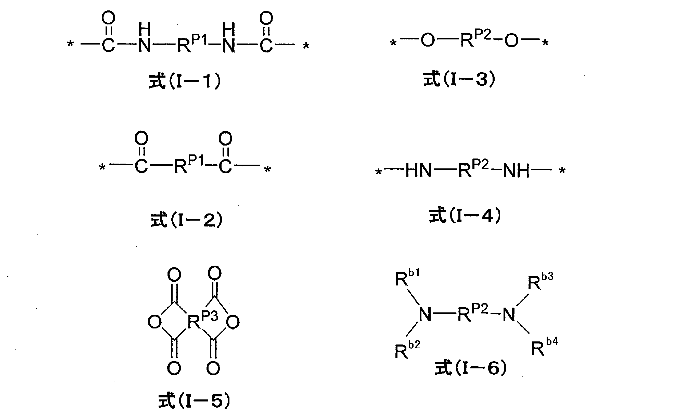
RP1及びRP2としてとりうる上記分子鎖は、特に制限されず、炭化水素鎖、ポリアルキレンオキシド鎖、ポリカーボネート鎖又はポリエステル鎖が好ましく、炭化水素鎖又はポリアルキレンオキシド鎖がより好ましい。
低分子量の炭化水素鎖は、通常の(比重合性の)炭化水素基からなる鎖であり、この炭化水素基としては、例えば、脂肪族若しくは芳香族の炭化水素基が挙げられ、具体的には、アルキレン基(炭素数は1~12が好ましく、1~6がより好ましく、1~3が更に好ましい)、アリーレン基(炭素数は6~22が好ましく、6~14が好ましく、6~10がより好ましい)、又はこれらの組み合わせからなる基が好ましい。RP2としてとりうる低分子量の炭化水素鎖を形成する炭化水素基としては、アルキレン基がより好ましく、炭素数2~6のアルキレン基が更に好ましく、炭素数2又は3のアルキレン基が特に好ましい。
芳香族の炭化水素基は、フェニレン基又は下記式(M2)で表される炭化水素基が好ましい。

RM2~RM5は、それぞれ、水素原子又は置換基を示し、水素原子が好ましい。RM2~RM5としてとりうる置換基としては、特に制限されないが、例えば、炭素数1~20のアルキル基、炭素数1~20のアルケニル基、-ORM6、―N(RM6)2、-SRM6(RM6は置換基を示し、好ましくは炭素数1~20のアルキル基又は炭素数6~10のアリール基を示す。)、ハロゲン原子(例えば、フッ素原子、塩素原子、臭素原子)が挙げられる。―N(RM6)2としては、アルキルアミノ基(炭素数は、1~20が好ましく、1~6がより好ましい)又はアリールアミノ基(炭素数は、6~40が好ましく、6~20がより好ましい)が挙げられる。
末端反応性基を有する炭化水素ポリマーとしては、例えば、いずれも商品名で、NISSO-PBシリーズ(日本曹達社製)、クレイソールシリーズ(巴工業社製)、PolyVEST-HTシリーズ(エボニック社製)、poly-bdシリーズ(出光興産社製)、poly-ipシリーズ(出光興産社製)、EPOL(出光興産社製)及びポリテールシリーズ(三菱化学社製)等が好適に用いられる。
ポリカーボネート鎖又はポリエステル鎖としては、公知のポリカーボネート又はポリエステルからなる鎖が挙げられる。
ポリアルキレンオキシド鎖、ポリカーボネート鎖又はポリエステル鎖は、それぞれ、末端にアルキル基(炭素数は1~12が好ましく、1~6がより好ましい)を有することが好ましい。
上記分子鎖の分子量又は質量平均分子量は、30以上が好ましく、50以上がより好ましく、100以上が更に好ましく、150以上が特に好ましい。上限としては、100,000以下が好ましく、10,000以下がより好ましい。分子鎖の分子量又は質量平均分子量は、ポリマーの主鎖に組み込む前の原料化合物について測定する。
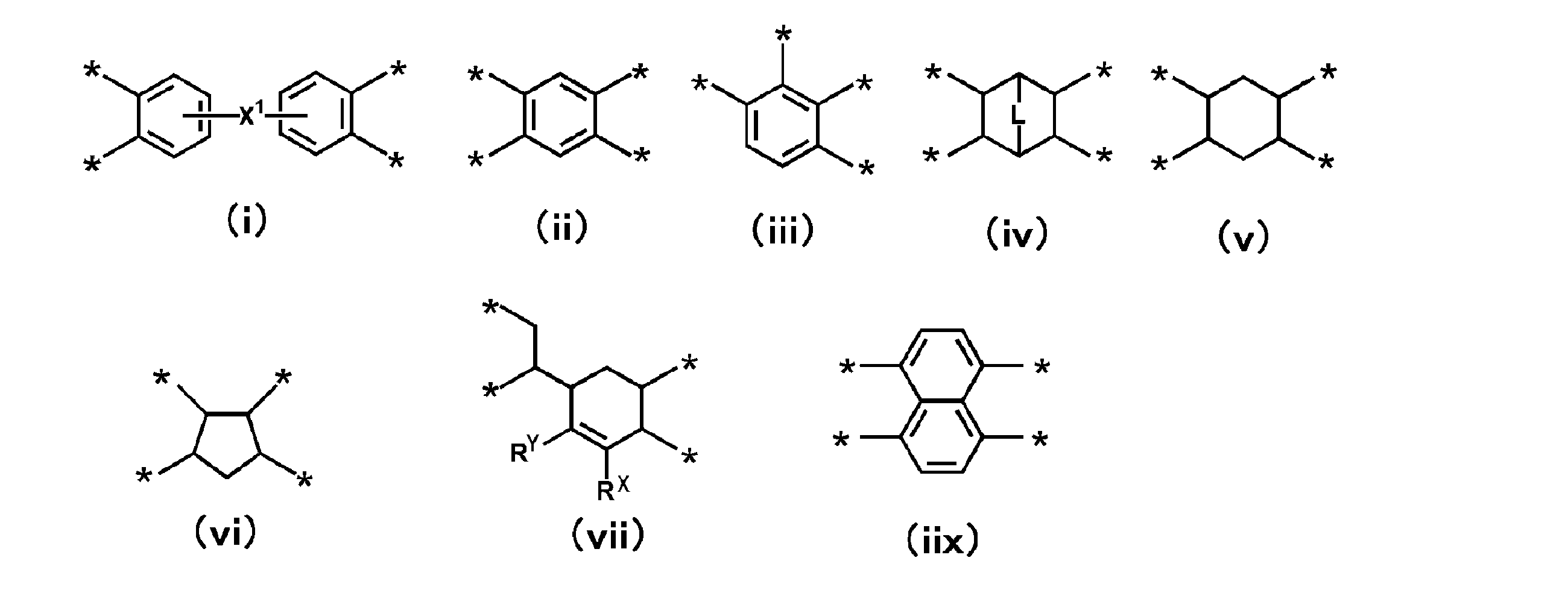

なお、バインダを構成するポリマー中における上記各式で表される構成成分の含有量は後述する。
(B)バインダを構成するポリマーは、このポリマーが有する上記主鎖の少なくとも1つの末端が、下記一般式(1)で表される分子量150以上の基(末端封止基)で封止されている。この基が重合体を含んでいる場合、上記分子量は数平均分子量を示す。

Xは-O-が好ましく、Yは-NRa1-又は-S-が好ましく、-S-がより好ましい。
Ra1で示されるアルキル基及びアリール基として、後述の置換基Tとして記載されたアルキル基及びアリール基が挙げられる。
Ra2で示される置換基として、後述の置換基Tが挙げられる。
(B)バインダを構成するポリマーが上記末端封止基を有することは、例えば、1H-NMRにより確認できる。
上記分子量は、例えば、アルカリ加水分解-GC/MS法及び上記末端封止基を導く原料化合物の分子量から求めることができる。

R11~R13で示されるアルキル基又はアリール基は、後述の置換基Tとして記載されたアルキル基又はアリール基が好ましい。
R14で示される置換基は、分子量10~200の置換基が好ましく、分子量15~100の置換基がより好ましく、例えば、ヒドロキシ基、アルコキシ基、アルキル基、アリール基及びカルボキシ基が挙げられる。

R14は、アルキル基、アルケニル基、又はアリール基を示す。
なお、-C(=O)-O-は、酸素原子でR14に結合することが好ましく、-C(=O)-NRa3-は、窒素原子でR14に結合することが好ましい。

L3はアルキレン基、-C(=O)-O-若しくは-O-又はこれら2つの組合わせを示す。L4はアルキレン基又は「アルキレン基-O-」を示す。R15は置換基を示す。
ただし、一般式(4)で表される基が1つの置換基(例えばアルキル基)と解釈できる場合、tは0とする。
アルキレン基は、直鎖、分岐及び環状のいずれでもよく、炭素数は1~20が好ましく、2~10がより好ましく、2~6がさらに好ましい。アルキレン基の具体例は、メチレン、エチレン、メチルエチレン、1,1-ジメチルエチレン、ブチレン、へキシレン及びシクロへキシレンが挙げられる。
アルキル基の炭素数は、1~30が好ましく、1~20がより好ましく、1~10が特に好ましく、直鎖、分岐及び環状のいずれでもよい。アルキル基の具体例として、メチル、エチル、プロピル、ブチル、t-ブチル、ペンチル、2,2-ジメチルプロピル、シクロヘキシル及びドデシルが挙げられる。
tが0である場合、L3がアルキレン基、R15がアルキル基を採るとき、L3のアルキレン基の炭素数が最大となるように解釈する。例えば、実施例で合成した末端封止基を導入するための原料化合物A-5では、L3が炭素数7のアルキレン基で、R15がメチルと解釈する。

SP値は有機溶剤に分散する特性を示す指標となる。ここで、末端封止基を特定の分子量以上とし、好ましくは上記SP値以上とすることで、無機固体電解質との結着性を向上させ、かつ、これにより有機溶剤との親和性を高め、安定に分散させることができ好ましい。SP値は以下のようにして算出することができる。
SPp 2=SP1 2+SP2 2+・・・
ここで、繰り返し単位のSP値は、特に断らない限り、Hoy法によって求めた値(H.L.Hoy Journal of Painting,1970,Vol.42,76-118)とする。
アルキル基(好ましくは炭素数1~20のアルキル基、例えばメチル、エチル、イソプロピル、t-ブチル、ペンチル、ヘプチル、1-エチルペンチル、ベンジル、2-エトキシエチル、1-カルボキシメチル等)、アルケニル基(好ましくは炭素数2~20のアルケニル基、例えば、ビニル、アリル、オレイル等)、アルキニル基(好ましくは炭素数2~20のアルキニル基、例えば、エチニル、ブタジイニル、フェニルエチニル等)、シクロアルキル基(好ましくは炭素数3~20のシクロアルキル基、例えば、シクロプロピル、シクロペンチル、シクロヘキシル、4-メチルシクロヘキシル等)、アリール基(好ましくは炭素数6~26のアリール基、例えば、フェニル、1-ナフチル、4-メトキシフェニル、2-クロロフェニル、3-メチルフェニル等)、ヘテロ環基(好ましくは炭素数2~20のヘテロ環基で、好ましくは、少なくとも1つの酸素原子、硫黄原子、窒素原子を有する5又は6員環のヘテロ環基である。ヘテロ環基には芳香族ヘテロ環基(ヘテロアリール基)及び脂肪族ヘテロ環基を含む。例えば、テトラヒドロピラン環基、テトラヒドロフラン環基、2-ピリジル、4-ピリジル、2-イミダゾリル、2-ベンゾイミダゾリル、2-チアゾリル、2-オキサゾリル等)、アルコキシ基(好ましくは炭素数1~20のアルコキシ基、例えば、メトキシ、エトキシ、イソプロピルオキシ、ベンジルオキシ等)、アリールオキシ基(好ましくは炭素数6~26のアリールオキシ基、例えば、フェノキシ、1-ナフチルオキシ、3-メチルフェノキシ、4-メトキシフェノキシ等)、ヘテロ環オキシ基(上記ヘテロ環基に-O-基が結合した基)、アルコキシカルボニル基(好ましくは炭素数2~20のアルコキシカルボニル基、例えば、エトキシカルボニル、2-エチルヘキシルオキシカルボニル、ドデシルオキシカルボニル等)、アリールオキシカルボニル基(好ましくは炭素数6~26のアリールオキシカルボニル基、例えば、フェノキシカルボニル、1-ナフチルオキシカルボニル、3-メチルフェノキシカルボニル、4-メトキシフェノキシカルボニル等)、アミノ基(好ましくは炭素数0~20のアミノ基、アルキルアミノ基、アリールアミノ基を含み、例えば、アミノ(-NH2)、N,N-ジメチルアミノ、N,N-ジエチルアミノ、N-エチルアミノ、アニリノ等)、スルファモイル基(好ましくは炭素数0~20のスルファモイル基、例えば、N,N-ジメチルスルファモイル、N-フェニルスルファモイル等)、アシル基(アルキルカルボニル基、アルケニルカルボニル基、アルキニルカルボニル基、アリールカルボニル基、ヘテロ環カルボニル基を含み、好ましくは炭素数1~20のアシル基、例えば、アセチル、プロピオニル、ブチリル、オクタノイル、ヘキサデカノイル、アクリロイル、メタクリロイル、クロトノイル、ベンゾイル、ナフトイル、ニコチノイル等)、アシルオキシ基(アルキルカルボニルオキシ基、アルケニルカルボニルオキシ基、アルキニルカルボニルオキシ基、アリールカルボニルオキシ基、ヘテロ環カルボニルオキシ基を含み、好ましくは炭素数1~20のアシルオキシ基、例えば、アセチルオキシ、プロピオニルオキシ、ブチリルオキシ、オクタノイルオキシ、ヘキサデカノイルオキシ、アクリロイルオキシ、メタクリロイルオキシ、クロトノイルオキシ、ベンゾイルオキシ、ナフトイルオキシ、ニコチノイルオキシ等)、アリーロイルオキシ基(好ましくは炭素数7~23のアリーロイルオキシ基、例えば、ベンゾイルオキシ等)、カルバモイル基(好ましくは炭素数1~20のカルバモイル基、例えば、N,N-ジメチルカルバモイル、N-フェニルカルバモイル等)、アシルアミノ基(好ましくは炭素数1~20のアシルアミノ基、例えば、アセチルアミノ、ベンゾイルアミノ等)、アルキルチオ基(好ましくは炭素数1~20のアルキルチオ基、例えば、メチルチオ、エチルチオ、イソプロピルチオ、ベンジルチオ等)、アリールチオ基(好ましくは炭素数6~26のアリールチオ基、例えば、フェニルチオ、1-ナフチルチオ、3-メチルフェニルチオ、4-メトキシフェニルチオ等)、ヘテロ環チオ基(上記ヘテロ環基に-S-基が結合した基)、アルキルスルホニル基(好ましくは炭素数1~20のアルキルスルホニル基、例えば、メチルスルホニル、エチルスルホニル等)、アリールスルホニル基(好ましくは炭素数6~22のアリールスルホニル基、例えば、ベンゼンスルホニル等)、アルキルシリル基(好ましくは炭素数1~20のアルキルシリル基、例えば、モノメチルシリル、ジメチルシリル、トリメチルシリル、トリエチルシリル等)、アリールシリル基(好ましくは炭素数6~42のアリールシリル基、例えば、トリフェニルシリル等)、ホスホリル基(好ましくは炭素数0~20のリン酸基、例えば、-OP(=O)(RP)2)、ホスホニル基(好ましくは炭素数0~20のホスホニル基、例えば、-P(=O)(RP)2)、ホスフィニル基(好ましくは炭素数0~20のホスフィニル基、例えば、-P(RP)2)、スルホ基(スルホン酸基)、カルボキシ基、ヒドロキシ基、スルファニル基、シアノ基、ハロゲン原子(例えばフッ素原子、塩素原子、臭素原子、ヨウ素原子等)が挙げられる。RPは、水素原子又は置換基(好ましくは置換基Tから選択される基)である。
また、これらの置換基Tで挙げた各基は、上記置換基Tが更に置換していてもよい。
バインダを構成するポリマー中の、上記各式で表される構成成分以外の構成成分の含有量は、特に限定されず、50質量%以下であることが好ましい。
バインダを構成するポリマーの構成成分及び末端封止基の含有量の合計中の、式(I-3)、式(I-4)又は式(I-6)で表される化合物由来の構成成分の含有量は、特に制限されず、10~50モル%であることが好ましく、20~50モル%であることがより好ましく、30~50モル%であることが更に好ましい。
バインダを構成するポリマーの構成成分及び末端封止基の含有量の合計中の、末端封止基の含有量は、特に制限されず、0.1~10モル%であることが好ましく、0.2~5モル%であることがより好ましく、0.4~5モル%であることが更に好ましく、0.7~3モル%であることが更に好ましい。末端封止基の含有量(モル%)とは、ポリマーを構成する各構成成分及び末端封止基の含有量の合計を100モル中の末端封止基のモルの割合である。
なお、バインダを構成するポリマーが各式で表される構成成分を複数有する場合、各構成成分の上記含有量は合計含有量とする。
式(I-3)又は式(I-4)で表される構成成分のうち、RP2が分子鎖として上記ポリアルキレンオキシド鎖である構成成分の、バインダを構成するポリマー中の含有量は、特に制限されず、例えば、0~50モル%であることが好ましく、10~45モル%であることがより好ましく、20~43モル%であることが更に好ましい。
式(I-3)又は式(I-4)で表される構成成分のうち、RP2が分子鎖として上記炭化水素ポリマー鎖である構成成分の、バインダを構成するポリマー中の含有量は、特に制限されず、例えば、0~50モル%であることが好ましく、1~45モル%であることがより好ましく、3~40モル%であることが更に好ましく、3~30モル%であることが更に好ましく、3~20モル%であることが更に好ましく、3~10モル%であることが更に好ましい。
上記式(I-3)又は式(I-4)で表される構成成分を導く原料化合物(ジオール化合物又はジアミン化合物)は、それぞれ、特に制限されず、例えば、国際公開第2018/020827号に記載の各化合物及びその具体例が挙げられ、更にジヒドロキシオキサミドも挙げられる。
上記式(I-5)で表されるカルボン酸二無水物、及び上記式(I-6)で表される原料化合物(ジアミン化合物)は、それぞれ、特に制限されず、例えば、国際公開第2018/020827号及び国際公開第2015/046313号に記載の各化合物及びその具体例が挙げられる。

上述のポリマー(ポリマーからなるバインダ)は、分散媒に対して可溶であってもよいが、特にイオン伝導性の点で、分散媒に対して不溶(の粒子)であることが好ましい。
本発明において、分散媒に対して不溶であるとは、ポリマーを30℃の分散媒(使用量はポリマーの質量に対して10倍)に添加し、24時間静置しても、分散媒への溶解量が3質量%以下であることを意味し、2質量%以下であることが好ましく、1質量%以下であることがより好ましい。ここの溶解量は、分散媒に添加したポリマー質量に対する、24時間経過後に分散媒から固液分離して得られるポリマー質量の割合とする。
粒子状バインダの平均粒径は、特に制限されないが、1000nm以下であることが好ましく、500nm以下であることがより好ましく、300nm以下であることが更に好ましい。下限値は1nm以上であり、5nm以上であることが好ましく、10nm以上であることがより好ましく、50nm以上であることが更に好ましい。平均粒径は、上記無機固体電解質の平均粒径と同様にして測定できる。
上記ポリマーの質量平均分子量は、特に制限されない。例えば、15000以上が好ましく、30000以上がより好ましく、50000以上が更に好ましい。上限としては、400000以下が実質的であるが、200000以下が好ましく、100000以下がより好ましい。
上記ポリマーの水分濃度は、100ppm(質量基準)以下が好ましい。また、このポリマーは、晶析させて乾燥させてもよく、ポリマー分散液をそのまま用いてもよい。
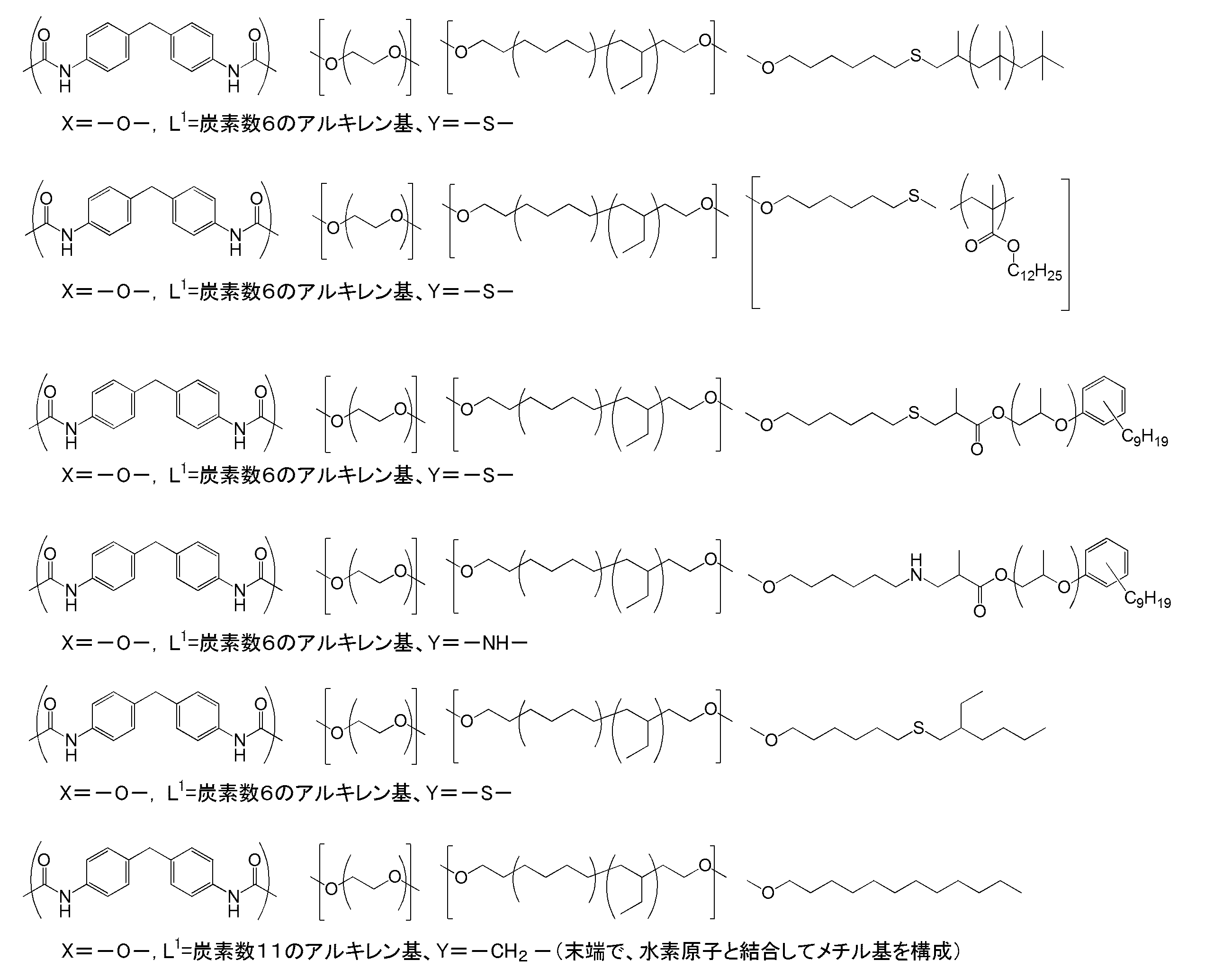
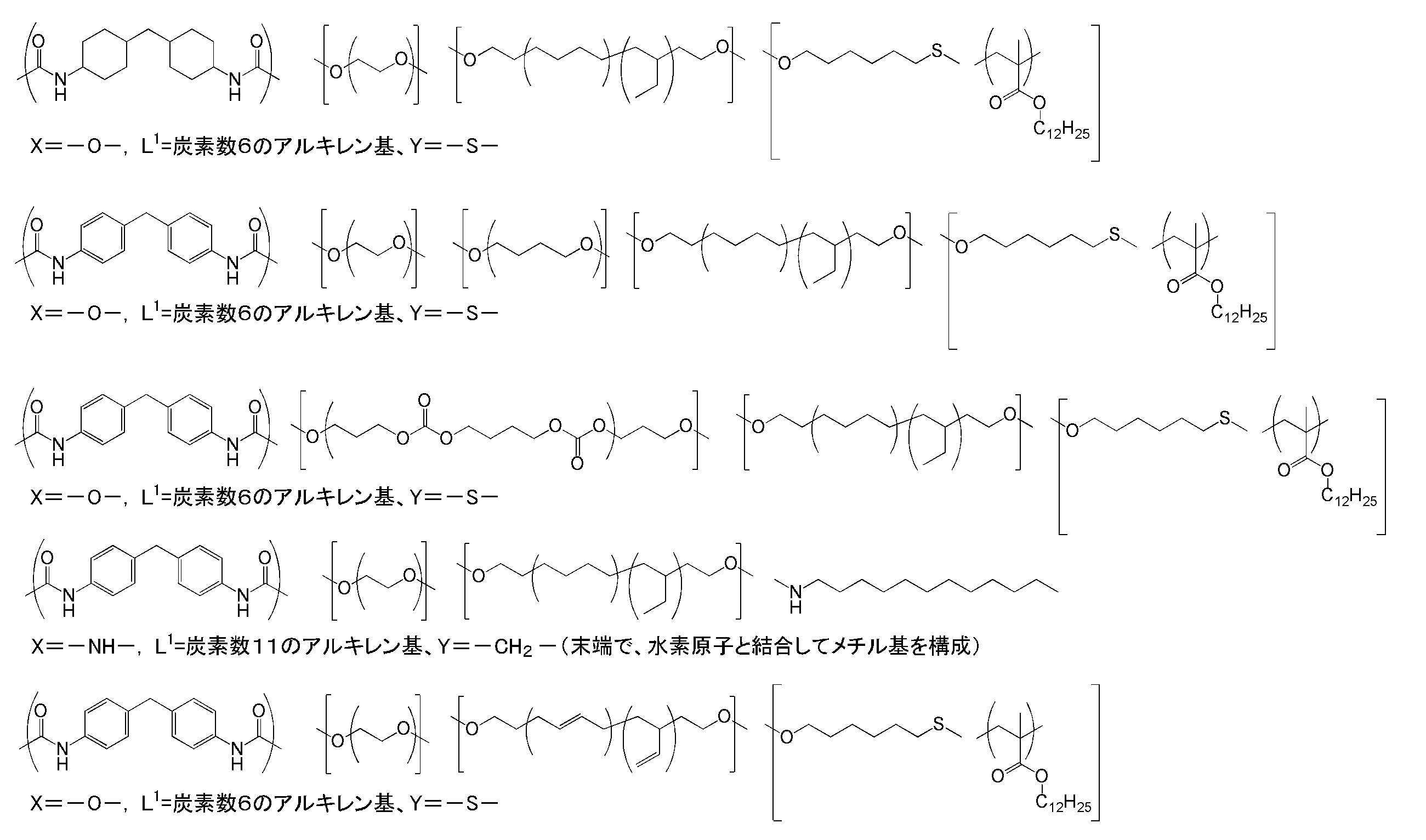

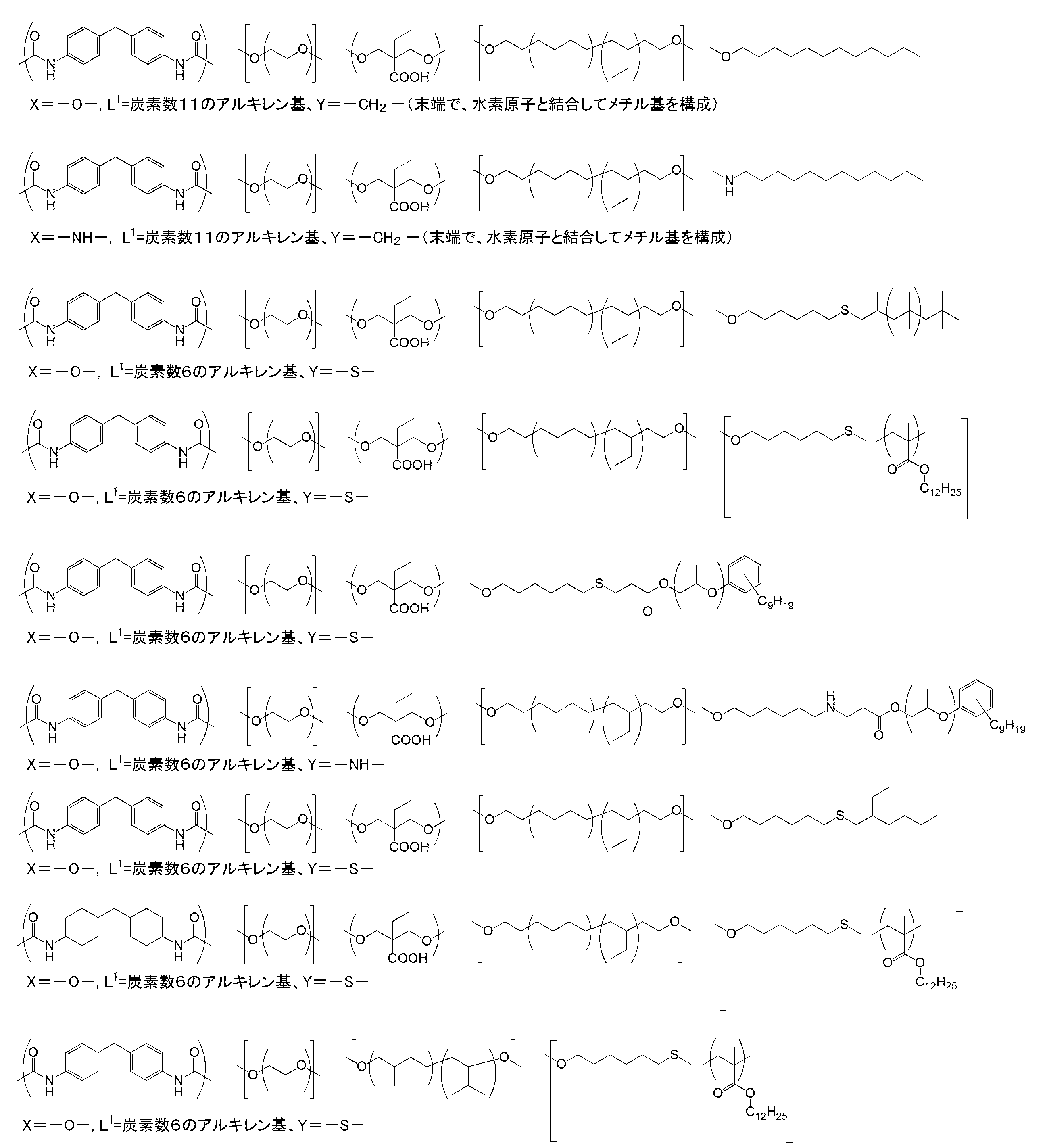
本発明の固体電解質組成物において、(B)バインダの質量に対する、無機固体電解質と活物質の合計質量(総量)の質量比[(無機固体電解質の質量+活物質の質量)/(バインダの質量)]は、1,000~1の範囲が好ましい。この比率は500~2がより好ましく、100~5が更に好ましい。
本発明の固体電解質組成物は、周期律表第1族若しくは第2族に属する金属元素のイオンの挿入放出が可能な活物質を含有してもよい。
活物質としては、正極活物質及び負極活物質が挙げられ、正極活物質である遷移金属酸化物、又は、負極活物質である金属酸化物が好ましい。
本発明において、活物質(正極活物質及び負極活物質)を含有する固体電解質組成物を、電極用組成物(正極用組成物及び負極用組成物)ということがある。
本発明の固体電解質組成物が含有してもよい正極活物質は、可逆的にリチウムイオンを挿入及び放出できるものが好ましい。その材料は、上記特性を有するものであれば、特に制限はなく、遷移金属酸化物、有機物、硫黄などのLiと複合化できる元素、又は、硫黄と金属の複合物などでもよい。
中でも、正極活物質としては、遷移金属酸化物を用いることが好ましく、遷移金属元素Ma(Co、Ni、Fe、Mn、Cu及びVから選択される1種以上の元素)を有する遷移金属酸化物がより好ましい。また、この遷移金属酸化物に元素Mb(リチウム以外の金属周期律表の第1(Ia)族の元素、第2(IIa)族の元素、Al、Ga、In、Ge、Sn、Pb、Sb、Bi、Si、P又はBなどの元素)を混合してもよい。混合量としては、遷移金属元素Maの量(100mol%)に対して0~30mol%が好ましい。Li/Maのモル比が0.3~2.2になるように混合して合成されたものが、より好ましい。
遷移金属酸化物の具体例としては、(MA)層状岩塩型構造を有する遷移金属酸化物、(MB)スピネル型構造を有する遷移金属酸化物、(MC)リチウム含有遷移金属リン酸化合物、(MD)リチウム含有遷移金属ハロゲン化リン酸化合物及び(ME)リチウム含有遷移金属ケイ酸化合物等が挙げられる。
(MB)スピネル型構造を有する遷移金属酸化物の具体例として、LiMn2O4(LMO)、LiCoMnO4、Li2FeMn3O8、Li2CuMn3O8、Li2CrMn3O8及びLi2NiMn3O8が挙げられる。
(MC)リチウム含有遷移金属リン酸化合物としては、例えば、LiFePO4及びLi3Fe2(PO4)3等のオリビン型リン酸鉄塩、LiFeP2O7等のピロリン酸鉄類、LiCoPO4等のリン酸コバルト類並びにLi3V2(PO4)3(リン酸バナジウムリチウム)等の単斜晶ナシコン型リン酸バナジウム塩が挙げられる。
(MD)リチウム含有遷移金属ハロゲン化リン酸化合物としては、例えば、Li2FePO4F等のフッ化リン酸鉄塩、Li2MnPO4F等のフッ化リン酸マンガン塩及びLi2CoPO4F等のフッ化リン酸コバルト類が挙げられる。
(ME)リチウム含有遷移金属ケイ酸化合物としては、例えば、Li2FeSiO4、Li2MnSiO4及びLi2CoSiO4等が挙げられる。
本発明では、(MA)層状岩塩型構造を有する遷移金属酸化物が好ましく、LCO、LMO、NCA又はNMCがより好ましい。
正極活物質層を形成する場合、正極活物質層の単位面積(cm2)当たりの正極活物質の質量(mg)(目付量)は特に限定されるものではない。設計された電池容量に応じて、適宜に決めることができる。
本発明の固体電解質組成物が含有してもよい負極活物質は、可逆的にリチウムイオンを挿入及び放出できるものが好ましい。その材料は、上記特性を有するものであれば、特に制限はなく、炭素質材料、酸化錫等の金属酸化物、酸化ケイ素、金属複合酸化物、リチウム単体及びリチウムアルミニウム合金等のリチウム合金、並びに、Sn、Si、Al及びIn等のリチウムと合金形成可能な金属等が挙げられる。中でも、炭素質材料又はリチウム複合酸化物が信頼性の点から好ましく用いられる。また、金属複合酸化物としては、リチウムを吸蔵及び放出可能であることが好ましい。その材料は、特には制限されず、構成成分としてチタン及び/又はリチウムを含有していることが、高電流密度充放電特性の観点で好ましい。
Si負極に用いられる負極活物質の具体例として、Si及びSiOx(0<x≦1)が挙げられる。
負極活物質層を形成する場合、負極活物質層の単位面積(cm2)当たりの負極活物質の質量(mg)(目付量)は特に限定されるものではない。設計された電池容量に応じて、適宜に決めることができる。
また、正極活物質又は負極活物質を含む電極表面は硫黄又はリンで表面処理されていてもよい。
更に、正極活物質又は負極活物質の粒子表面は、上記表面被覆の前後において活性光線又は活性気体(プラズマ等)により表面処理を施されていてもよい。
本発明の固体電解質組成物は、導電助剤を含有してもよい。導電助剤としては、特に制限はなく、一般的な導電助剤として知られているものを用いることができる。例えば、電子伝導性材料である、天然黒鉛、人造黒鉛などの黒鉛類、アセチレンブラック、ケッチェンブラック、ファーネスブラックなどのカーボンブラック類、ニードルコークスなどの無定形炭素、気相成長炭素繊維若しくはカーボンナノチューブなどの炭素繊維類、グラフェン若しくはフラーレンなどの炭素質材料であってもよいし、銅、ニッケルなどの金属粉、金属繊維でもよく、ポリアニリン、ポリピロール、ポリチオフェン、ポリアセチレン、ポリフェニレン誘導体など導電性高分子を用いてもよい。またこれらの内1種を用いてもよいし、2種以上を用いてもよい。
本発明において、負極活物質と導電助剤とを併用する場合、電池を充放電した際にLiの挿入と放出が起きず、負極活物質として機能しないものを導電助剤とする。したがって、導電助剤の中でも、電池を充放電した際に負極活物質層中において負極活物質として機能しうるものは、導電助剤ではなく負極活物質に分類する。電池を充放電した際に負極活物質として機能するか否かは、一義的に言うことができず、負極活物質との組み合わせにおいて決定される。
導電助剤の含有量は、固体電解質組成物中の固形分100質量%に対して、0~10質量%が好ましく、3~7質量%がより好ましい。
本発明の固体電解質組成物は、固形成分を分散させるため分散媒を含有することが好ましい。
分散媒体は、上記の各成分を分散させるものであればよく、例えば、各種の有機溶媒が挙げられる。分散媒の具体例としては下記のものが挙げられる。
上記分散媒は、1種を単独で用いても、2種以上を組み合わせて用いてもよい。
また、固体電解質組成物の分散性をより向上させるため、分散媒のSP値が18~21MPa1/2であることが好ましい。SP値が上記範囲にある分散媒の具体例として、酢酸ブチル、ヘプタン、シクロオクタン、ジブチルケトン及びジブチルエーテルが挙げられる。
また、分散媒のSP値と上記一般式(1)で表される末端封止基のSP値との差(分散媒のSP値-上記一般式(1)で表される末端封止基のSP値)は、固体電解質組成物の分散性をより向上させるため、0.1~5MPa1/2であることが好ましく、0.1~3MPa1/2であることがより好ましい。
なお、SP値の算出方法は、上述の「末端封止基が重合体を含まない場合」の算出方法と同様である。
本発明の固体電解質組成物は、リチウム塩を含有してもよい。
リチウム塩としては、特に制限はなく、例えば、特開2015-088486号公報の段落0082~0085記載のリチウム塩が好ましい。
リチウム塩の含有量は、固体電解質組成物中の固形分100質量部に対して、0質量部以上が好ましく、2質量部以上がより好ましい。上限としては、20質量部以下が好ましく、10質量部以下がより好ましい。
本発明の固体電解質組成物は、本発明の効果を損なわない範囲内で、上述の(B)バインダの他に、通常用いられるバインダを含有してもよい。
通常用いられるバインダとしては有機ポリマーが挙げられ、例えば、以下に述べる樹脂からなるバインダが好ましく使用される。
炭化水素系熱可塑性樹脂としては、例えば、ポリエチレン、ポリプロピレン、スチレンブタジエンゴム(SBR)、水素添加スチレンブタジエンゴム(HSBR)、ブチレンゴム、アクリロニトリル-ブタジエンゴム、ポリブタジエン、ポリイソプレンが挙げられる。アクリル樹脂としては、各種の(メタ)アクリルモノマー類、(メタ)アクリルアミドモノマー類、及びこれら樹脂を構成するモノマーの共重合体(好ましくは、アクリル酸とアクリル酸メチルとの共重合体)が挙げられる。
また、その他のビニル系モノマーとの共重合体(コポリマー)も好適に用いられる。
その他の樹脂としては例えばポリウレタン樹脂、ポリウレア樹脂、ポリアミド樹脂、ポリイミド樹脂、ポリエステル樹脂、ポリエーテル樹脂、ポリカーボネート樹脂、セルロース誘導体樹脂等が挙げられる。
これらは1種を単独で用いても、2種以上を組み合わせて用いてもよい。
本発明の固体電解質組成物は、(A)無機固体電解質及び(B)バインダ、必要により、(E)分散媒又は他の成分を、例えば、各種の混合機を用いて、混合することにより、調製することができる。好ましくは、(A)無機固体電解質及び(B)バインダと、必要により(E)分散媒、他の成分を分散媒に分散させたスラリーとして、調製できる。
固体電解質組成物のスラリーは、各種の混合機を用いて調製できる。混合装置としては、特に限定されないが、例えば、ボールミル、ビーズミル、プラネタリミキサ―、ブレードミキサ―、ロールミル、ニーダー及びディスクミルが挙げられる。混合条件は特に制限されないが、例えば、ボールミルを用いた場合、150~700rpm(rotation per minute)で1時間~24時間混合することが好ましい。
分散媒を含有しない固体電解質組成物を調製する場合には、上記の(A)無機固体電解質の分散工程と同時に添加及び混合してもよく、別途添加及び混合してもよい。なお、(B)バインダは、(A)無機固体電解質及び/又は(C)活物質若しくは(D)導電助剤等の成分の分散工程と同時に添加及び混合してもよく、別途添加及び混合してもよい。また、本発明の固体電解質組成物に添加及び/又は混合する際の(B)バインダの形態は、(B)バインダそのものであっても、(B)バインダの溶液であっても、(B)バインダの分散液(ポリマーの非水溶媒分散物)であってもよい。中でも、無機固体電解質の分解を抑制し、かつ、活物質と無機固体電解質の粒子表面に点在化してイオン伝導度を担保できる点からは、バインダの分散液が好ましい。
本発明の全固体二次電池用シートは、(A)周期律表第1族若しくは第2族に属する金属のイオンの伝導性を有する無機固体電解質と、(B)バインダとを含有する層を有する。この(B)バインダは、特に断りがない限り、本発明の固体電解質組成物における(B)バインダと同義である。
この全固体二次電池用シートは、固体電解質層又は活物質層を有していれば、他の層を有してもよいが、活物質を含有するものは全固体二次電池用電極シートに分類される。他の層としては、例えば、保護層、集電体、導電体層等が挙げられる。
全固体二次電池用固体電解質シートとして、例えば、固体電解質層と、必要により保護層とを基材上に、この順で有するシートが挙げられる。
全固体二次電池用シートの固体電解質層の層厚は、本発明の全固体二次電池において説明する固体電解質層の層厚と同じである。
このシートは、本発明の固体電解質組成物、好ましくは、(A)無機固体電解質と、(B)バインダと、(E)分散媒とを含有する固体電解質組成物を基材上(他の層を介していてもよい)に製膜(塗布乾燥)して、基材上に固体電解質層を形成することにより、得られる。詳細は後述する。
ここで、本発明の固体電解質組成物は、上記の方法によって、調製できる。
電極シートを構成する各層の構成及び層厚は、後記の、本発明の全固体二次電池において説明した各層の構成及び層厚と同じである。
電極シートは、本発明の、活物質を含有する固体電解質組成物を金属箔上に製膜(塗布乾燥)して、金属箔上に活物質層を形成することにより、得られる。詳細は後述する。
本発明の全固体二次電池は、正極と、この正極に対向する負極と、正極及び負極の間の固体電解質層とを有する。正極は、正極集電体上に正極活物質層を有する。負極は、負極集電体上に負極活物質層を有する。
負極活物質層、正極活物質層及び固体電解質層の少なくとも1つの層は、本発明の固体電解質組成物を用いて形成され、(A)無機固体電解質と(B)バインダとを含有する。
固体電解質組成物を用いて形成された活物質層及び/又は固体電解質層は、好ましくは、含有する成分種及びその含有量比について、特段の断りをしない限り、固体電解質組成物の固形分におけるものと同じである。
本発明の全固体二次電池は積層型であってもよく、この積層型全固体二次電池は、負極活物質層、固体電解質層及び正極活物質層を1ユニットとして、1~100ユニット有する形態が好ましく、2~50ユニット有する形態がより好ましい。
本明細書において、正極活物質層(以下、正極層とも称す。)と負極活物質層(以下、負極層とも称す。)を合わせて電極層又は活物質層と称することがある。また、正極活物質及び負極活物質のいずれか、又は両方を合わせて、単に、活物質又は電極活物質と称することがある。
全固体二次電池10においては、正極活物質層、固体電解質層及び負極活物質層のいずれかが本発明の固体電解質組成物を用いて作製されている。
すなわち、固体電解質層3が本発明の固体電解質組成物を用いて作製されている場合、固体電解質層3は、(A)無機固体電解質と(B)バインダとを含む。固体電解質層は、通常、正極活物質及び/又は負極活物質を含まない。
正極活物質層4及び/又は負極活物質層2が、活物質を含有する本発明の固体電解質組成物を用いて作製されている場合、正極活物質層4及び負極活物質層2は、それぞれ、正極活物質又は負極活物質を含み、更に、(A)無機固体電解質と(B)バインダとを含む。活物質層が無機固体電解質を含有するとイオン伝導度を向上させることができる。
正極活物質層4、固体電解質層3及び負極活物質層2が含有する(A)無機固体電解質及び(B)バインダは、それぞれ、互いに同種であっても異種であってもよい。
本発明において、全固体二次電池における負極活物質層、正極活物質層及び固体電解質層が、いずれも、上記固体電解質組成物で作製されることが好ましい態様の1つである。
正極集電体5及び負極集電体1は、電子伝導体が好ましい。
本発明において、正極集電体及び負極集電体のいずれか、又は、両方を合わせて、単に、集電体と称することがある。
正極集電体を形成する材料としては、アルミニウム、アルミニウム合金、ステンレス鋼、ニッケル、チタンなどの他に、アルミニウム又はステンレス鋼の表面にカーボン、ニッケル、チタンあるいは銀を処理させたもの(薄膜を形成したもの)が好ましく、その中でも、アルミニウム及びアルミニウム合金がより好ましい。
負極集電体を形成する材料としては、アルミニウム、銅、銅合金、ステンレス鋼、ニッケル、チタンなどの他に、アルミニウム、銅、銅合金又はステンレス鋼の表面にカーボン、ニッケル、チタンあるいは銀を処理させたものが好ましく、アルミニウム、銅、銅合金及びステンレス鋼がより好ましい。
集電体の厚みは、特に限定されないが、1~500μmが好ましい。また、集電体表面は、表面処理により凹凸を付けることも好ましい。
上記の各層を配置して全固体二次電池の基本構造を作製することができる。用途によってはこのまま全固体二次電池として使用してもよいが、乾電池の形態とするためには更に適当な筐体に封入して用いる。筐体は、金属性のものであっても、樹脂(プラスチック)製のものであってもよい。金属性のものを用いる場合には、例えば、アルミニウム合金及びステンレス鋼製のものを挙げることができる。金属性の筐体は、正極側の筐体と負極側の筐体に分けて、それぞれ正極集電体及び負極集電体と電気的に接続させることが好ましい。正極側の筐体と負極側の筐体とは、短絡防止用のガスケットを介して接合され、一体化されることが好ましい。
本発明の全固体二次電池用シートは、本発明の固体電解質組成物(好ましくは(E)分散媒を含有する。)を基材上(導電体層等の他の層を介していてもよい)に製膜(塗布乾燥)して、基材上に固体電解質層を形成することにより、得られる。
上記態様により、(A)無機固体電解質と(B)バインダとを(含有する固体電解質層を)基材上に有する全固体二次電池用シートを作製することができる。また、作製した全固体二次電池用シートから基材を剥がし、固体電解質層からなる全固体二次電池用シートを作製することもできる。
その他、塗布等の工程については、下記全固体二次電池の製造に記載の方法を使用することができる。
本発明の全固体二次電池用シート中の(E)分散媒の含有割合は、以下の方法で測定することができる。
全固体二次電池用シートを20mm角で打ち抜き、ガラス瓶中で重テトラヒドロフランに浸漬させる。得られた溶出物をシリンジフィルターでろ過して1H-NMRにより定量操作を行う。1H-NMRピーク面積と溶媒の量の相関性は検量線を作成して求める。
全固体二次電池及び全固体二次電池用電極シートの製造は、常法によって行うことができる。具体的には、全固体二次電池及び全固体二次電池用電極シートは、本発明の固体電解質組成物等を用いて、上記の各層を形成することにより、製造できる。以下詳述する。
例えば、正極集電体である金属箔上に、正極用材料(正極用組成物)として、正極活物質を含有する固体電解質組成物を塗布して正極活物質層を形成し、全固体二次電池用正極シートを作製する。次いで、この正極活物質層の上に、固体電解質層を形成するための固体電解質組成物を塗布して、固体電解質層を形成する。更に、固体電解質層の上に、負極用材料(負極用組成物)として、負極活物質を含有する固体電解質組成物を塗布して、負極活物質層を形成する。負極活物質層の上に、負極集電体(金属箔)を重ねることにより、正極活物質層と負極活物質層の間に固体電解質層が挟まれた構造の全固体二次電池を得ることができる。必要によりこれを筐体に封入して所望の全固体二次電池とすることができる。
また、各層の形成方法を逆にして、負極集電体上に、負極活物質層、固体電解質層及び正極活物質層を形成し、正極集電体を重ねて、全固体二次電池を製造することもできる。
また別の方法として、次の方法が挙げられる。すなわち、上記のようにして、全固体二次電池用正極シート及び全固体二次電池用負極シートを作製する。また、これとは別に、固体電解質組成物を基材上に塗布して、固体電解質層からなる全固体二次電池用固体電解質シートを作製する。更に、全固体二次電池用正極シート及び全固体二次電池用負極シートで、基材から剥がした固体電解質層を挟むように積層する。このようにして、全固体二次電池を製造することができる。
固体電解質組成物の塗布方法は、特に限定されず、適宜に選択できる。例えば、塗布(好ましくは湿式塗布)、スプレー塗布、スピンコート塗布、ディップコート、スリット塗布、ストライプ塗布及びバーコート塗布が挙げられる。
このとき、固体電解質組成物は、それぞれ塗布した後に乾燥処理を施してもよいし、重層塗布した後に乾燥処理をしてもよい。乾燥温度は特に限定されない。下限は30℃以上が好ましく、60℃以上がより好ましく、80℃以上が更に好ましい。上限は、300℃以下が好ましく、250℃以下がより好ましく、200℃以下が更に好ましい。このような温度範囲で加熱することで、(E)分散媒を除去し、固体状態にすることができる。また、温度を高くしすぎず、全固体二次電池の各部材を損傷せずに済むため好ましい。これにより、全固体二次電池において、優れた総合性能を示し、かつ良好な結着性を得ることができる。
また、塗布した固体電解質組成物は、加圧と同時に加熱してもよい。加熱温度としては、特に限定されず、一般的には30~300℃の範囲である。無機固体電解質のガラス転移温度よりも高い温度でプレスすることもできる。
加圧は塗布溶媒又は分散媒をあらかじめ乾燥させた状態で行ってもよいし、溶媒又は分散媒が残存している状態で行ってもよい。
各組成物は同時に塗布してもよいし、塗布乾燥プレスを同時及び/又は逐次行ってもよい。別々の基材に塗布した後に、転写により積層してもよい。
プレス時間は短時間(例えば数時間以内)で高い圧力をかけてもよいし、長時間(1日以上)かけて中程度の圧力をかけてもよい。全固体二次電池用シート以外、例えば全固体二次電池の場合には、中程度の圧力をかけ続けるために、全固体二次電池の拘束具(ネジ締め圧等)を用いることもできる。
プレス圧はシート面等の被圧部に対して均一であっても異なる圧であってもよい。
プレス圧は被圧部の面積又は膜厚に応じて変化させることができる。また同一部位を段階的に異なる圧力で変えることもできる。
プレス面は平滑であっても粗面化されていてもよい。
上記のようにして製造した全固体二次電池は、製造後又は使用前に初期化を行うことが好ましい。初期化は、特に限定されず、例えば、プレス圧を高めた状態で初充放電を行い、その後、全固体二次電池の一般使用圧力になるまで圧力を開放することにより、行うことができる。
本発明の全固体二次電池は種々の用途に適用することができる。適用態様には特に限定はなく、例えば、電子機器に搭載する場合、ノートパソコン、ペン入力パソコン、モバイルパソコン、電子ブックプレーヤー、携帯電話、コードレスフォン子機、ページャー、ハンディーターミナル、携帯ファックス、携帯コピー、携帯プリンター、ヘッドフォンステレオ、ビデオムービー、液晶テレビ、ハンディークリーナー、ポータブルCD、ミニディスク、電気シェーバー、トランシーバー、電子手帳、電卓、携帯テープレコーダー、ラジオ、バックアップ電源、メモリーカードなどが挙げられる。その他民生用として、自動車(電気自動車等)、電動車両、モーター、照明器具、玩具、ゲーム機器、ロードコンディショナー、時計、ストロボ、カメラ、医療機器(ペースメーカー、補聴器、肩もみ機など)などが挙げられる。更に、各種軍需用、宇宙用として用いることができる。また、太陽電池と組み合わせることもできる。
無機固体電解質とは、上述した高分子化合物をイオン伝導媒体とする電解質(高分子電解質)とは区別されるものであり、無機化合物がイオン伝導媒体となるものである。具体例としては、上記のLi-P-S系ガラス、LLT若しくはLLZが挙げられる。無機固体電解質は、それ自体が陽イオン(Liイオン)を放出するものではなく、イオンの輸送機能を示すものである。これに対して、電解液ないし固体電解質層に添加して陽イオン(Liイオン)を放出するイオンの供給源となる材料を電解質と呼ぶことがある。上記のイオン輸送材料としての電解質と区別する際には、これを「電解質塩」又は「支持電解質」と呼ぶ。電解質塩としては、例えばLiTFSIが挙げられる。
本発明において「組成物」というときには、2種以上の成分が均一に混合された混合物を意味する。ただし、実質的に均一性が維持されていればよく、所望の効果を奏する範囲で、一部において凝集又は偏在が生じていてもよい。
硫化物系無機固体電解質として、T.Ohtomo,A.Hayashi,M.Tatsumisago,Y.Tsuchida,S.HamGa,K.Kawamoto,Journal of Power Sources,233,(2013),pp231-235及びA.Hayashi,S.Hama,H.Morimoto,M.Tatsumisago,T.Minami,Chem.Lett.,(2001),pp872-873の非特許文献を参考にして、Li-P-S系ガラスを合成した。
ジルコニア製45mL容器(フリッチュ社製)に、直径5mmのジルコニアビーズを66g投入し、上記の硫化リチウムと五硫化二リンの混合物全量を投入し、アルゴン雰囲気下で容器を密閉した。フリッチュ社製遊星ボールミルP-7(商品名、フリッチュ社製)に容器をセットし、温度25℃で、回転数510rpmで20時間メカニカルミリングを行うことで、黄色粉体の硫化物系無機固体電解質(Li-P-S系ガラス、LPSと表記することがある。)6.20gを得た。
<バインダポリマーS-1の合成>
200mL3つ口フラスコに、ポリエチレングリコール(富士フイルム和光純薬社製、商品名 ポリエチレングリコール 200)4.46gと、2,2-ビス(ヒドロキシメチル)酪酸(東京化成社製)0.55g、NISSO-PB GI-1000(商品名、日本曹達社製)5.58gとを加え、THF(テトラヒドロフラン)74gに溶解した。この溶液に、ジフェニルメタンジイソシアネート(和光純薬社製)7.76gを加えて60℃で撹拌し、均一に溶解させた。得られた溶液に、ネオスタンU-600(商品名、日東化成社製)560mgを添加して60℃で5時間攪伴し、粘性ポリマー溶液を得た。このポリマー溶液に1-ドデカノール(和光純薬社製)0.23gを加えてポリマー末端を封止して、重合反応を停止し、ポリマーS-1の20質量%THF溶液(ポリマー溶液)を得た。
次に、上記で得られたポリマー溶液に対してTHF74gを加えた溶液に、150rpmで撹拌しながら、ヘプタン222gを10分間かけて滴下し、ポリマーS-1の乳化液を得た。窒素ガスをフローしながらこの乳化液を85℃で120分加熱した。得られた残留物後にヘプタン50gを加えて更に85℃で60分加熱した。この操作を4回繰り返し、THFを除去した。こうして、ポリマーS-1からなるバインダーのヘプタン分散液を得た。
バインダポリマーS-1の合成において、下記表1に記載の原料化合物の組成を採用したこと以外は、バインダポリマーS-1と同様にして、バインダポリマーS-2~S-15及びT-1~T-6を合成した。
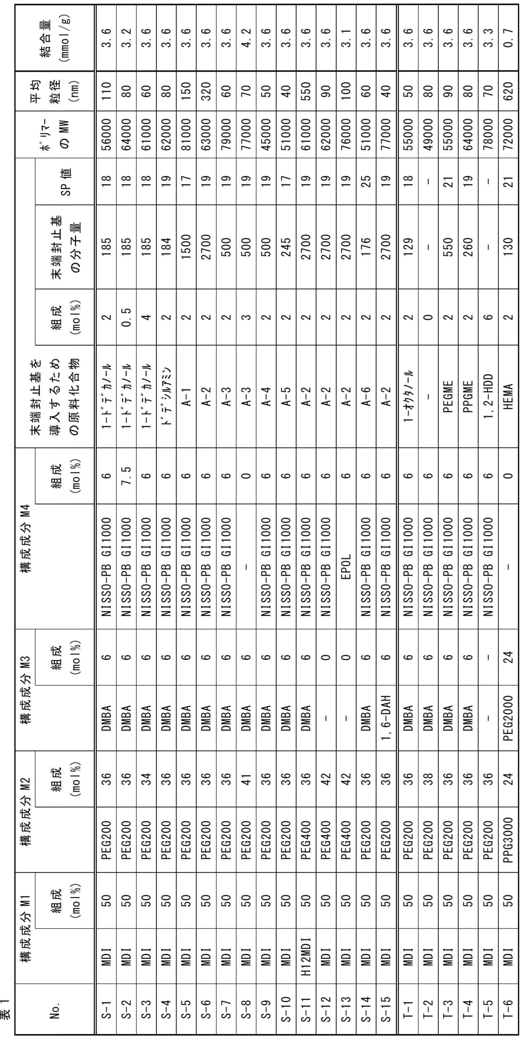
構成成分M2:式(I-3B)で表される構成成分
構成成分M3:式(I-3A)で表される構成成分又は式(I-3A)で表される構成成分において両末端の酸素原子をNHに変更した構成成分
構成成分M4:式(I-3C)で表される構成成分
なお、バインダポリマーT-6の各構成成分は各構成成分欄に順に記載した。
MDI:ジフェニルメタンジイソシアネート
H12MDI:ジシクロヘキシルメタン4,4'-ジイソシアナート
PEG200:ポリエチレングリコール 200(商品名、富士フイルム和光純薬社製)
PEG400:ポリエチレングリコール 400(商品名、富士フイルム和光純薬社製)
PEG2000:ポリエチレングリコール 2000(商品名、富士フイルム和光純薬社製)
PPG3000:ポリプロピレングリコール、ジオール型、3000(商品名、富士フイルム和光純薬社製)
DMBA:2,2-ビス(ヒドロキシメチル)酪酸
NISSO-PB GI1000:日本曹達社製商品名、両末端水酸基水素化ポリブタジエン
EPOL(出光興産社、登録商標):水酸基末端液状ポリオレフィン
PEGME:ポリエチレングリコールモノメチルエーテル
PPGME:ポリプロピレングリコールモノメチルエーテル
1,6-DAH:1,6-ジアミノヘキサン
1,2-HDD:1,2-ヘキサデカンジオール
HEMA:メタクリル酸2-ヒドロキシエチル
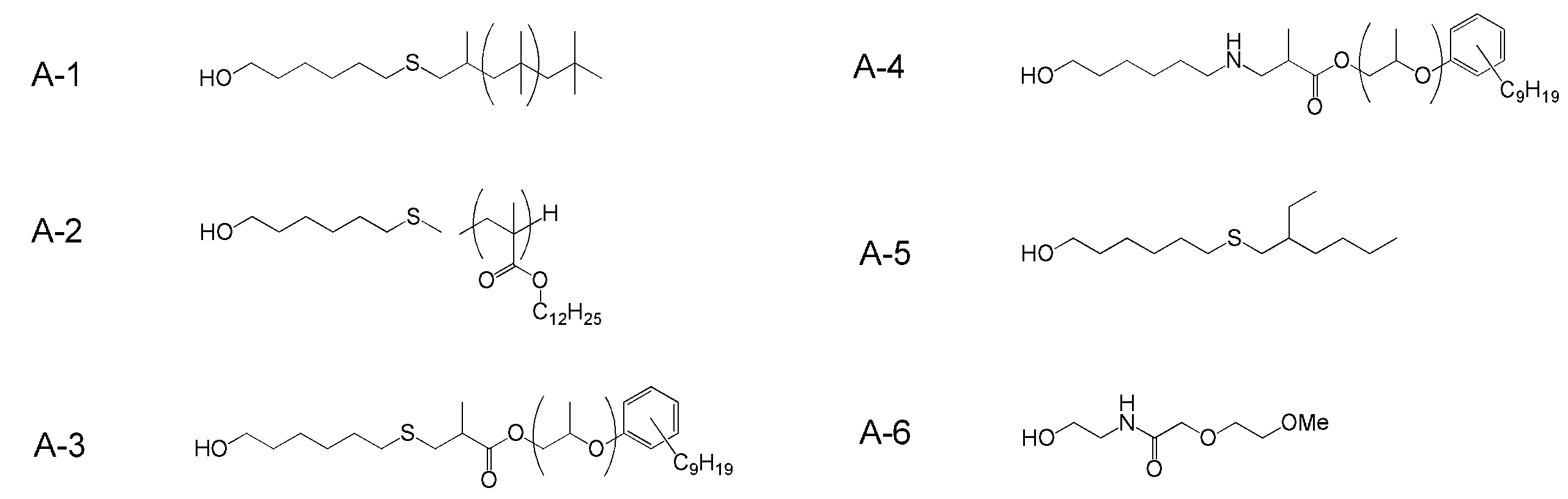
<固体電解質組成物、正極用組成物及び負極用組成物の調製>
上記合成したバインダポリマーを用いて以下のようにして、後記表2に記載する、固体電解質組成物、正極用組成物及び負極用組成物を調製した。
ジルコニア製45mL容器(フリッチュ社製)に、直径5mmのジルコニアビーズを180個投入し、下記表2に記載の組成で各成分を投入した。その後に、この容器をフリッチュ社製遊星ボールミルP-7(商品名)にセットし、温度25℃、回転数150rpmで10分間混合を続けて、固体電解質組成物K-1~K-18及びKc11~Kc16を調製した。
ジルコニア製45mL容器(フリッチュ社製)に、直径5mmのジルコニアビーズを180個投入し、上記合成したLPSを2.7g、表1に示すバインダポリマーの分散液又は溶液、及び分散媒を投入した。フリッチュ社製遊星ボールミルP-7(商品名)にこの容器をセットし、25℃で、回転数150rpmで10分間攪拌した。その後、活物質を投入し、同様にして、遊星ボールミルP-7に容器をセットし、25℃、回転数100rpmで5分間混合を続け、正極用組成物PK-1、負極用組成物NK-1~NK-12、NKc21~NKc24をそれぞれ調製した。
上記調製した固体電解質組成物に対して下記分散安定性試験を行った。結果を後記表1に記載する。
調製した固体電解質組成物を直径10mm、高さ15cmのガラス試験管に高さ10cmまで加え、25℃で2時間静置した後に、分離した上澄みの高さを目視で確認して測定した。固体電解質組成物の全量(高さ10cm)に対する上澄みの高さの比:上澄みの高さ/全量の高さを求めた。この比が下記評価ランクのいずれに含まれるかにより、固体電解質組成物の分散性(分散安定性)を評価した。上記比を算出するに際し、全量とはガラス試験管に投入した固体電解質組成物の全量(10cm)をいい、上澄みの高さとは固体電解質組成物の固形成分が沈降して生じた(固液分離した)上澄み液の量(cm)をいう。
本試験において、上記比が小さいほど、分散性に優れることを示し、評価ランク「D」以上が合格レベルである。
-評価基準-
A: 上澄みの高さ/全量の高さ<0.1
B:0.1≦上澄みの高さ/全量の高さ<0.3
C:0.3≦上澄みの高さ/全量の高さ<0.5
D:0.5≦上澄みの高さ/全量の高さ<0.7
E:0.7≦上澄みの高さ/全量の高さ<0.9
F:0.9≦上澄みの高さ/全量の高さ


LLT:Li0.33La0.55TiO3(平均粒径3.25μm豊島製作所製)
Li-P-S:上記で合成したLi-P-S系ガラス
NMC:LiNi1/3Co1/3Mn1/3O2(ニッケルマンガンコバルト酸リチウム)
AB:アセチレンブラック
VGCF:商品名、昭和電工社製カーボンナノファイバー
Si:Siパウダー(商品名APS:1~5μm、Alfa Aesar社製)
黒鉛:CGB20(商品名、平均粒径20μm、日本黒鉛社製)
<全固体二次電池用シートの作製>
以下のようにして、後記表3に記載する全固体二次電池用固体電解質シート及び全固体二次電池用電極シートを作製した。
上記で得られた各固体電解質組成物を厚み20μmのアルミ箔上に、アプリケーター(商品名:SA-201ベーカー式アプリケーター、テスター産業社製)により塗布し、80℃で2時間加熱し、固体電解質組成物を乾燥させた。その後、ヒートプレス機を用いて、120℃の温度及び600MPaの圧力で10秒間、乾燥させた固体電解質組成物を加熱及び加圧し、全固体二次電池用固体電解質シート101~118及びc11~c16を作製した。固体電解質層の膜厚は50μmであった。
上記で得られた正極又は負極用組成物を厚み20μmのアルミニウム箔(正極集電体)又は銅箔(負極集電体)上に、ベーカー式アプリケーター(商品名:SA-201、テスター産業社製)により塗布し、80℃で2時間加熱し、乾燥(分散媒を除去)した。その後、ヒートプレス機を用いて、乾燥させた正極又は負極用組成物を25℃で加圧(10MPa、1分)し、膜厚80μmの正極又は負極活物質層を有する各シートを作製した。
次いで、各シートの活物質層上に、上記で作製した全固体二次電池用シートを固体電解質層が正極又は負極活物質層に接するように重ね、プレス機を用いて25℃で50MPa加圧して転写(積層)した後に、25℃で600MPa加圧することで、膜厚50μmの固体電解質層を備えた全固体二次電池用正極シート117、全固体二次電池用負極シート118~131及びc21~c24をそれぞれ作製した。
上記で作製した全固体二次電池用シートについて、以下の試験を行った。以下に試験方法を記載し、結果を下記表3にまとめて記載する。
以下のようにして、イオン伝導度測定用試験体を作製した。
(1)全固体二次電池用固体電解質シートを用いたイオン伝導度測定用試験体の作製
上記で得られた全固体二次電池用固体電解質シートを直径14.5mmの円板状に切り出し、この全固体二次電池用固体電解質シート12を図2に示す2032型コインケース11に入れた。具体的には、直径15mmの円板状に切り出したアルミ箔(図2に図示しない)を固体電解質層と接触させ、スペーサーとワッシャー(ともに図2において図示しない)を組み込んで、ステンレス製の2032型コインケース11に入れた。2032型コインケース11をかしめることで、8ニュートン(N)の力で締め付けられた、イオン伝導度測定用試験体13を作製した。
上記で作製した2枚の全固体二次電池用電極シート(全固体二次電池用電極シートのうち、固体電解質層側のアルミニウム箔は剥離済み)から、それぞれ、直径14.5mmの円板状シートを切り出した。切り出した2枚の円盤状シートの固体電解質層同士を貼り合わせて、積層体(集電体-電極活物質層-固体電解質層-固体電解質層-電極活物質層-集電体からなる積層体)12を作製した。この積層体12をイオン伝導度測定用試料として、スペーサーとワッシャー(図2に示しない)を組み込んで、ステンレス製の2032型コインケース11に入れた。2032型コインケース11をかしめることで、8ニュートン(N)の力で締め付けられた、図2に示す構成を有するイオン伝導度測定用試験体13を作製した。
式(1):イオン伝導度σ(mS/cm)=
1000×試料層厚(cm)/[抵抗(Ω)×試料面積(cm2)]
式(1)において、試料層厚は、積層体12を2032型コインケース11に入れる前に測定し、2枚の集電体の厚みを差し引いた値(固体電解質層の層厚又は固体電解質層及び電極活物質層の合計層厚)である。試料面積は、直径14.5mmの円板状シートの面積である。
本試験におけるイオン伝導度は、評価ランク「D」以上が合格である。
-イオン伝導度の評価ランク-
A:0.60≦σ
B:0.50≦σ<0.60
C:0.40≦σ<0.50
D:0.30≦σ<0.40
E:0.20≦σ<0.30
F: σ<0.20
上記で得た各シートから3cm×14cmの長方形の試験片を切り出した。切り出した試験片を、円筒形マンドレル試験機「商品コード056」(マンドレル直径10mm、Allgood社製)を用いての日本工業規格(JIS) K5600-5-1(耐屈曲性(円筒形マンドレル:タイプ2の試験装置を用いた試験)、国際標準規格(ISO)1519と同試験。)に従って、屈曲させた。固体電解質層をマンドレルとは逆側(基材をマンドレル側)にセットした。
屈曲後、屈曲部分を含む3cm×8cmの範囲を目視にて観察し、欠陥の発生状態を調べた、欠陥の発生状態を下記評価基準に当てはめて、シートの強度を評価した。「C」以上が合格である。なお、「A」~「C」では構成層と基材との剥離も生じなかった。
-マンドレル試験評価基準-
A:欠陥(欠け、割れ、ヒビ、剥がれ)が全く見られなかった。
B:観測対象とした面積に占める欠陥部分の面積の割合が、0%越え10%以下
C:観測対象とした面積に占める欠陥部分の面積の割合が、10%越え30%以下
D:観測対象とした面積に占める欠陥部分の面積の割合が、30%越え50%以下
E:観測対象とした面積に占める欠陥部分の面積の割合が、50%越え70%以下
F:観測対象とした面積に占める欠陥部分の面積の割合が、70%越え
欠陥部分の面積は、固体電解質層の表面積に換算した面積(投影面積)である。

バインダーポリマーNo.:各組成物に含まれるバインダーポリマーのNo.を示す。
<全固体二次電池の作製>
以下のようにして、図1に示す層構成を有する全固体二次電池(No.101)を作製した。
上記で得られた全固体二次電池用正極シートを直径14.5mmの円板状に切り出し、スペーサーとワッシャー(図2において図示せず)を組み込んだステンレス製の2032型コインケース11に入れ、固体電解質層上に15mmφに切り出したリチウム箔を重ねた。その上にさらにステンレス箔を重ねた後、2032型コインケース11をかしめることで、図2に示すNo.101の全固体二次電池13を作製した。
このようにして製造した全固体二次電池は、図1に示す層構成を有する(ただし、リチウム箔が、負極活物質層2及び負極集電体1に相当する)。
表4に記載の固体電解質組成物K-2及び負極用組成物NK-2を用いて上記と同様にして負極シートを作製した。この負極シートの固体電解質層上に下記のようにして調製した正極用組成物をベーカー式アプリケーター(商品名:SA-201、テスター産業社製)により塗布し、80℃で2時間加熱し、乾燥(分散媒を除去)することにより正極活物質層を形成して積層体を得た。この積層体を直径14.5mmの円板状に切り出し、スペーサーとワッシャー(図2において図示せず)を組み込んだステンレス製の2032型コインケース11に入れ、正極活物質層上に15mmφに切り出したアルミニウム箔を重ね、全固体二次電池用積層体を作製した。2032型コインケース11をかしめることで、図2に示すNo.102の全固体二次電池13を作製した。
ジルコニア製45mL容器(フリッチュ社製)に、直径5mmのジルコニアビーズを180個投入し、上記で合成したLPSを2.7g、KYNAR FLEX 2500-20(商品名、PVdF-HFP:ポリフッ化ビニリデンヘキサフルオロプロピレン共重合体、アルケマ社製)を固形分質量として0.3g、及び酪酸ブチルを22g投入した。フリッチュ社製遊星ボールミルP-7(商品名)にこの容器をセットし、25℃で、回転数300rpmで60分間攪拌した。その後、正極活物質としてLiNi1/3Co1/3Mn1/3O2(NMC)7.0gを投入し、同様にして、遊星ボールミルP-7に容器をセットし、25℃、回転数100rpmで5分間混合を続け、正極用組成物を調製した。
上記で作製した全固体二次電池について、以下の試験を行った。以下に試験方法を記載し、結果を下記表4に記載する。
上記のようにして作製した全固体二次電池No.101~116及びc101~c104について、その放電容量維持率を測定して、サイクル特性を評価した。
具体的には、各全固体二次電池の放電容量維持率を、充放電評価装置:TOSCAT-3000(商品名、東洋システム社製)により測定した。充電は、電流密度0.1mA/cm2で電池電圧が3.6Vに達するまで行った。放電は、電流密度0.1mA/cm2で電池電圧が2.5Vに達するまで行った。この充電1回と放電1回とを充放電1サイクルとして3サイクル充放電を繰り返して、全固体二次電池を初期化した。初期化後の充放電1サイクル目の放電容量(初期放電容量)を100%としたときに、放電容量維持率(初期放電容量に対する放電容量)が80%に達した際の充放電サイクル数が、下記評価ランクのいずれに含まれるかにより、サイクル特性を評価した。下記評価ランクにおいて、「C」以上が合格である。
-放電容量維持率の評価ランク-
A:500サイクル以上
B:300サイクル以上、500サイクル未満
C:200サイクル以上、300サイクル未満
D:100サイクル以上、200サイクル未満
E: 50サイクル以上、100サイクル未満
F: 50サイクル未満

2 負極活物質層
3 固体電解質層
4 正極活物質層
5 正極集電体
6 作動部位
10 全固体二次電池
11 2032型コインケース
12 全固体二次電池用固体電解質シート、積層体又は全固体二次電池用積層体
13 イオン伝導度測定用試験体
Claims (15)
- (A)周期律表第1族若しくは第2族に属する金属のイオン伝導性を有する無機固体電解質と、(B)バインダとを含有し、
前記(B)バインダを構成するポリマーが、ウレタン結合、ウレア結合、アミド結合、イミド結合及びエステル結合のうちの少なくとも1つの結合を主鎖に有し、かつ、当該主鎖の少なくとも1つの末端が、下記一般式(1)で表される分子量150以上の、前記主鎖を構成する構成成分とは異なる基で封止された、固体電解質組成物。

- 前記一般式(1)で表される基のSP値が14MPa1/2以上24MPa1/2未満である、請求項1に記載の固体電解質組成物。
- 前記一般式(1)で表される基の含有量が、前記ポリマーの主鎖の各構成成分及び上記一般式(1)で表される基の合計100モル%中0.1~10モル%である、請求項1又は2に記載の固体電解質組成物。
- 前記Yが-S-を示し、前記R1が下記一般式(2)で表される基を示す、請求項1~3のいずれか1項に記載の固体電解質組成物。

- 前記(B)バインダの含有量が、前記固体電解質組成物が含有する全固形成分中、0.01~10質量%である、請求項1~4のいずれか1項に記載の固体電解質組成物。
- (C)活物質を含む、請求項1~5のいずれか1項に記載の固体電解質組成物。
- 前記(C)活物質が構成元素にSiを含む負極活物質である、請求項6に記載の固体電解質組成物。
- (D)導電助剤を含む、請求項1~7のいずれか1項に記載の固体電解質組成物。
- (E)分散媒を含む、請求項1~8のいずれか1項に記載の固体電解質組成物。
- 前記(E)分散媒のSP値が14~22MPa1/2である、請求項9に記載の固体電解質組成物。
- 前記(A)無機固体電解質が硫化物系無機固体電解質である、請求項1~10のいずれか1項に記載の固体電解質組成物。
- 請求項1~11のいずれか1項に記載の固体電解質組成物で形成した層を有する、全固体二次電池用シート。
- 正極活物質層と固体電解質層と負極活物質層とをこの順で具備する全固体二次電池であって、
前記正極活物質層、前記負極活物質層及び前記固体電解質層の少なくとも1層が、請求項1~11のいずれか1項に記載の固体電解質組成物で形成した層である、全固体二次電池。 - 請求項1~11のいずれか1項に記載の固体電解質組成物を塗布する工程を含む、全固体二次電池用シートの製造方法。
- 請求項1~11のいずれか1項に記載の固体電解質組成物を塗布する工程を含む、全固体二次電池の製造方法。
Priority Applications (3)
| Application Number | Priority Date | Filing Date | Title |
|---|---|---|---|
| JP2020563373A JP7096367B2 (ja) | 2018-12-26 | 2019-12-25 | 固体電解質組成物、全固体二次電池用シート及び全固体二次電池、並びに、全固体二次電池用シート若しくは全固体二次電池の製造方法 |
| KR1020217018254A KR20210089758A (ko) | 2018-12-26 | 2019-12-25 | 고체 전해질 조성물, 전고체 이차 전지용 시트와 전고체 이차 전지, 및 전고체 이차 전지용 시트 혹은 전고체 이차 전지의 제조 방법 |
| CN201980083673.9A CN113196521A (zh) | 2018-12-26 | 2019-12-25 | 固体电解质组合物、全固态二次电池用片材及全固态二次电池、以及全固态二次电池用片材或全固态二次电池的制造方法 |
Applications Claiming Priority (2)
| Application Number | Priority Date | Filing Date | Title |
|---|---|---|---|
| JP2018-243609 | 2018-12-26 | ||
| JP2018243609 | 2018-12-26 |
Publications (1)
| Publication Number | Publication Date |
|---|---|
| WO2020138216A1 true WO2020138216A1 (ja) | 2020-07-02 |
Family
ID=71127193
Family Applications (1)
| Application Number | Title | Priority Date | Filing Date |
|---|---|---|---|
| PCT/JP2019/050939 Ceased WO2020138216A1 (ja) | 2018-12-26 | 2019-12-25 | 固体電解質組成物、全固体二次電池用シート及び全固体二次電池、並びに、全固体二次電池用シート若しくは全固体二次電池の製造方法 |
Country Status (4)
| Country | Link |
|---|---|
| JP (1) | JP7096367B2 (ja) |
| KR (1) | KR20210089758A (ja) |
| CN (1) | CN113196521A (ja) |
| WO (1) | WO2020138216A1 (ja) |
Cited By (2)
| Publication number | Priority date | Publication date | Assignee | Title |
|---|---|---|---|---|
| JP2022146892A (ja) * | 2021-03-22 | 2022-10-05 | 株式会社リコー | 液体組成物、電極の製造方法、及び電気化学素子の製造方法 |
| WO2025204666A1 (ja) * | 2024-03-29 | 2025-10-02 | 本田技研工業株式会社 | 固体電池 |
Citations (4)
| Publication number | Priority date | Publication date | Assignee | Title |
|---|---|---|---|---|
| WO2016136089A1 (ja) * | 2015-02-27 | 2016-09-01 | 富士フイルム株式会社 | 固体電解質組成物、電池用電極シート及びその製造方法、並びに全固体二次電池及びその製造方法 |
| WO2017018456A1 (ja) * | 2015-07-30 | 2017-02-02 | 富士フイルム株式会社 | 固体電解質組成物、全固体二次電池用電極シートおよび全固体二次電池ならびに全固体二次電池用電極シートおよび全固体二次電池の製造方法 |
| JP2017130264A (ja) * | 2016-01-18 | 2017-07-27 | 富士フイルム株式会社 | 固体電解質組成物、全固体二次電池用固体電解質シート、全固体二次電池用電極シート、全固体二次電池及び分岐状ポリマーの製造方法 |
| JP2018206703A (ja) * | 2017-06-08 | 2018-12-27 | 三洋化成工業株式会社 | 全固体電池用バインダー、電極、固体電解質及び全固体電池 |
Family Cites Families (3)
| Publication number | Priority date | Publication date | Assignee | Title |
|---|---|---|---|---|
| JP6110823B2 (ja) * | 2013-09-25 | 2017-04-05 | 富士フイルム株式会社 | 固体電解質組成物および全固体二次電池用のバインダー、ならびにこれらを用いた電池用電極シートおよび全固体二次電池 |
| JP6059743B2 (ja) * | 2014-02-17 | 2017-01-11 | 富士フイルム株式会社 | 固体電解質組成物、これを用いた電池用電極シートおよび全固体二次電池、ならびにそれらの製造方法 |
| WO2018151118A1 (ja) | 2017-02-16 | 2018-08-23 | 富士フイルム株式会社 | 固体電解質組成物、固体電解質含有シート及びその製造方法、全固体二次電池及びその製造方法、並びに、ポリマー及びその非水溶媒分散物 |
-
2019
- 2019-12-25 WO PCT/JP2019/050939 patent/WO2020138216A1/ja not_active Ceased
- 2019-12-25 JP JP2020563373A patent/JP7096367B2/ja active Active
- 2019-12-25 KR KR1020217018254A patent/KR20210089758A/ko not_active Abandoned
- 2019-12-25 CN CN201980083673.9A patent/CN113196521A/zh active Pending
Patent Citations (4)
| Publication number | Priority date | Publication date | Assignee | Title |
|---|---|---|---|---|
| WO2016136089A1 (ja) * | 2015-02-27 | 2016-09-01 | 富士フイルム株式会社 | 固体電解質組成物、電池用電極シート及びその製造方法、並びに全固体二次電池及びその製造方法 |
| WO2017018456A1 (ja) * | 2015-07-30 | 2017-02-02 | 富士フイルム株式会社 | 固体電解質組成物、全固体二次電池用電極シートおよび全固体二次電池ならびに全固体二次電池用電極シートおよび全固体二次電池の製造方法 |
| JP2017130264A (ja) * | 2016-01-18 | 2017-07-27 | 富士フイルム株式会社 | 固体電解質組成物、全固体二次電池用固体電解質シート、全固体二次電池用電極シート、全固体二次電池及び分岐状ポリマーの製造方法 |
| JP2018206703A (ja) * | 2017-06-08 | 2018-12-27 | 三洋化成工業株式会社 | 全固体電池用バインダー、電極、固体電解質及び全固体電池 |
Cited By (2)
| Publication number | Priority date | Publication date | Assignee | Title |
|---|---|---|---|---|
| JP2022146892A (ja) * | 2021-03-22 | 2022-10-05 | 株式会社リコー | 液体組成物、電極の製造方法、及び電気化学素子の製造方法 |
| WO2025204666A1 (ja) * | 2024-03-29 | 2025-10-02 | 本田技研工業株式会社 | 固体電池 |
Also Published As
| Publication number | Publication date |
|---|---|
| KR20210089758A (ko) | 2021-07-16 |
| JPWO2020138216A1 (ja) | 2021-09-30 |
| CN113196521A (zh) | 2021-07-30 |
| JP7096367B2 (ja) | 2022-07-05 |
Similar Documents
| Publication | Publication Date | Title |
|---|---|---|
| US11967681B2 (en) | Method of manufacturing all-solid state secondary battery, electrode sheet for all-solid state secondary battery, and method of manufacturing electrode sheet for all-solid state secondary battery | |
| KR102224536B1 (ko) | 고체 전해질 조성물, 바인더 입자, 전고체 이차 전지용 시트, 전고체 이차 전지용 전극 시트 및 전고체 이차 전지와, 이들의 제조 방법 | |
| US10833351B2 (en) | Solid electrolyte composition, solid electrolyte-containing sheet, all-solid state secondary battery, and methods for manufacturing solid electrolyte composition, solid electrolyte-containing sheet, all-solid state secondary battery | |
| JP7008080B2 (ja) | 固体電解質組成物、固体電解質含有シート及び全固体二次電池並びに固体電解質含有シート及び全固体二次電池の製造方法 | |
| WO2017099247A1 (ja) | 固体電解質組成物、全固体二次電池用シート、全固体二次電池用電極シート及びその製造方法、並びに、全固体二次電池及びその製造方法 | |
| US20210143472A1 (en) | Solid electrolyte composition, solid electrolyte-containing sheet, electrode sheet for all-solid state secondary battery, all-solid state secondary battery, method of manufacturing solid electrolyte-containing sheet, method of manufacturing all-solid state secondary battery, and method of manufacturing particle binder | |
| JP7373577B2 (ja) | 無機固体電解質含有組成物、全固体二次電池用シート、全固体二次電池用電極シート及び全固体二次電池、並びに、全固体二次電池用シート及び全固体二次電池の製造方法 | |
| JP7320062B2 (ja) | 無機固体電解質含有組成物、全固体二次電池用シート、全固体二次電池用電極シート及び全固体二次電池、並びに、全固体二次電池用シート及び全固体二次電池の製造方法 | |
| CN110249468A (zh) | 固体电解质组合物、含固体电解质的片材及其制造方法、全固态二次电池及其制造方法、以及聚合物及其非水溶剂分散物及二醇化合物 | |
| CN114303258A (zh) | 含有无机固体电解质的组合物、全固态二次电池用片材及全固态二次电池、以及全固态二次电池用片材及全固态二次电池的制造方法 | |
| JP6621443B2 (ja) | 固体電解質組成物、固体電解質含有シートおよび全固体二次電池ならびに固体電解質含有シートおよび全固体二次電池の製造方法 | |
| WO2018016544A1 (ja) | 固体電解質組成物、固体電解質含有シートおよび全固体二次電池ならびに固体電解質含有シートおよび全固体二次電池の製造方法 | |
| JPWO2020075749A1 (ja) | 固体電解質組成物、全固体二次電池用シート、全固体二次電池用電極シート及び全固体二次電池 | |
| WO2020138122A1 (ja) | 固体電解質組成物、固体電解質含有シート及び全固体二次電池、並びに、固体電解質含有シート及び全固体二次電池の製造方法 | |
| WO2020067108A1 (ja) | 全固体二次電池の負極用組成物、全固体二次電池用負極シート及び全固体二次電池、並びに、全固体二次電池用負極シート及び全固体二次電池の製造方法 | |
| JP7218441B2 (ja) | 無機固体電解質含有組成物、全固体二次電池用シート及び全固体二次電池、並びに、全固体二次電池用シート及び全固体二次電池の各製造方法 | |
| JP7165750B2 (ja) | 固体電解質組成物、固体電解質含有シート及び全固体二次電池、並びに、固体電解質含有シート及び全固体二次電池の製造方法 | |
| JP7096367B2 (ja) | 固体電解質組成物、全固体二次電池用シート及び全固体二次電池、並びに、全固体二次電池用シート若しくは全固体二次電池の製造方法 | |
| WO2023054455A1 (ja) | 電極用シート及び全固体二次電池、並びに、電極用シート、電極シート及び全固体二次電池の製造方法 | |
| WO2023054425A1 (ja) | 電極組成物、全固体二次電池用電極シート及び全固体二次電池、並びに、電極組成物、全固体二次電池用電極シート及び全固体二次電池の製造方法 | |
| JP2018044111A (ja) | ポリマー、固体電解質、固体電解質組成物、無機固体電解質組成物、固体電解質含有シート、二次電池、全固体二次電池、固体電解質含有シートの製造方法、無機固体電解質含有シートの製造方法、二次電池の製造方法および全固体二次電池の製造方法 | |
| US12620619B2 (en) | Inorganic solid electrolyte-containing composition, sheet for all-solid state secondary battery, and all-solid state secondary battery, and manufacturing methods for sheet for all-solid state secondary battery and all-solid state secondary battery | |
| JP7791170B2 (ja) | 無機固体電解質含有組成物、全固体二次電池用シート及び全固体二次電池、並びに、全固体二次電池用シート及び全固体二次電池の製造方法 | |
| US20230261257A1 (en) | Inorganic solid electrolyte-containing composition, sheet for all-solid state secondary battery, and all-solid state secondary battery, and manufacturing methods for sheet for all-solid state secondary battery and all-solid state secondary battery |
Legal Events
| Date | Code | Title | Description |
|---|---|---|---|
| 121 | Ep: the epo has been informed by wipo that ep was designated in this application |
Ref document number: 19905025 Country of ref document: EP Kind code of ref document: A1 |
|
| ENP | Entry into the national phase |
Ref document number: 2020563373 Country of ref document: JP Kind code of ref document: A |
|
| ENP | Entry into the national phase |
Ref document number: 20217018254 Country of ref document: KR Kind code of ref document: A |
|
| NENP | Non-entry into the national phase |
Ref country code: DE |
|
| 122 | Ep: pct application non-entry in european phase |
Ref document number: 19905025 Country of ref document: EP Kind code of ref document: A1 |