WO2020138057A1 - 複合シートの製造方法、吸収性物品の製造方法、複合シートおよび吸収性物品 - Google Patents
複合シートの製造方法、吸収性物品の製造方法、複合シートおよび吸収性物品 Download PDFInfo
- Publication number
- WO2020138057A1 WO2020138057A1 PCT/JP2019/050561 JP2019050561W WO2020138057A1 WO 2020138057 A1 WO2020138057 A1 WO 2020138057A1 JP 2019050561 W JP2019050561 W JP 2019050561W WO 2020138057 A1 WO2020138057 A1 WO 2020138057A1
- Authority
- WO
- WIPO (PCT)
- Prior art keywords
- sheet
- composite sheet
- composite
- absorbent article
- continuous
- Prior art date
- Legal status (The legal status is an assumption and is not a legal conclusion. Google has not performed a legal analysis and makes no representation as to the accuracy of the status listed.)
- Ceased
Links
Images


Classifications
-
- A—HUMAN NECESSITIES
- A61—MEDICAL OR VETERINARY SCIENCE; HYGIENE
- A61F—FILTERS IMPLANTABLE INTO BLOOD VESSELS; PROSTHESES; DEVICES PROVIDING PATENCY TO, OR PREVENTING COLLAPSING OF, TUBULAR STRUCTURES OF THE BODY, e.g. STENTS; ORTHOPAEDIC, NURSING OR CONTRACEPTIVE DEVICES; FOMENTATION; TREATMENT OR PROTECTION OF EYES OR EARS; BANDAGES, DRESSINGS OR ABSORBENT PADS; FIRST-AID KITS
- A61F13/00—Bandages or dressings; Absorbent pads
- A61F13/15—Absorbent pads, e.g. sanitary towels, swabs or tampons for external or internal application to the body; Supporting or fastening means therefor; Tampon applicators
- A61F13/45—Absorbent pads, e.g. sanitary towels, swabs or tampons for external or internal application to the body; Supporting or fastening means therefor; Tampon applicators characterised by the shape
- A61F13/49—Absorbent pads, e.g. sanitary towels, swabs or tampons for external or internal application to the body; Supporting or fastening means therefor; Tampon applicators characterised by the shape specially adapted to be worn around the waist, e.g. diapers or nappies
-
- A—HUMAN NECESSITIES
- A61—MEDICAL OR VETERINARY SCIENCE; HYGIENE
- A61F—FILTERS IMPLANTABLE INTO BLOOD VESSELS; PROSTHESES; DEVICES PROVIDING PATENCY TO, OR PREVENTING COLLAPSING OF, TUBULAR STRUCTURES OF THE BODY, e.g. STENTS; ORTHOPAEDIC, NURSING OR CONTRACEPTIVE DEVICES; FOMENTATION; TREATMENT OR PROTECTION OF EYES OR EARS; BANDAGES, DRESSINGS OR ABSORBENT PADS; FIRST-AID KITS
- A61F13/00—Bandages or dressings; Absorbent pads
- A61F13/15—Absorbent pads, e.g. sanitary towels, swabs or tampons for external or internal application to the body; Supporting or fastening means therefor; Tampon applicators
- A61F13/51—Absorbent pads, e.g. sanitary towels, swabs or tampons for external or internal application to the body; Supporting or fastening means therefor; Tampon applicators characterised by the outer layers of the pads
-
- B—PERFORMING OPERATIONS; TRANSPORTING
- B05—SPRAYING OR ATOMISING IN GENERAL; APPLYING FLUENT MATERIALS TO SURFACES, IN GENERAL
- B05D—PROCESSES FOR APPLYING FLUENT MATERIALS TO SURFACES, IN GENERAL
- B05D7/00—Processes, other than flocking, specially adapted for applying liquids or other fluent materials to particular surfaces or for applying particular liquids or other fluent materials
- B05D7/24—Processes, other than flocking, specially adapted for applying liquids or other fluent materials to particular surfaces or for applying particular liquids or other fluent materials for applying particular liquids or other fluent materials
-
- B—PERFORMING OPERATIONS; TRANSPORTING
- B32—LAYERED PRODUCTS
- B32B—LAYERED PRODUCTS, i.e. PRODUCTS BUILT-UP OF STRATA OF FLAT OR NON-FLAT, e.g. CELLULAR OR HONEYCOMB, FORM
- B32B5/00—Layered products characterised by the non- homogeneity or physical structure, i.e. comprising a fibrous, filamentary, particulate or foam layer; Layered products characterised by having a layer differing constitutionally or physically in different parts
- B32B5/22—Layered products characterised by the non- homogeneity or physical structure, i.e. comprising a fibrous, filamentary, particulate or foam layer; Layered products characterised by having a layer differing constitutionally or physically in different parts characterised by the presence of two or more layers which are next to each other and are fibrous, filamentary, formed of particles or foamed
- B32B5/24—Layered products characterised by the non- homogeneity or physical structure, i.e. comprising a fibrous, filamentary, particulate or foam layer; Layered products characterised by having a layer differing constitutionally or physically in different parts characterised by the presence of two or more layers which are next to each other and are fibrous, filamentary, formed of particles or foamed one layer being a fibrous or filamentary layer
- B32B5/26—Layered products characterised by the non- homogeneity or physical structure, i.e. comprising a fibrous, filamentary, particulate or foam layer; Layered products characterised by having a layer differing constitutionally or physically in different parts characterised by the presence of two or more layers which are next to each other and are fibrous, filamentary, formed of particles or foamed one layer being a fibrous or filamentary layer another layer next to it also being fibrous or filamentary
-
- B—PERFORMING OPERATIONS; TRANSPORTING
- B32—LAYERED PRODUCTS
- B32B—LAYERED PRODUCTS, i.e. PRODUCTS BUILT-UP OF STRATA OF FLAT OR NON-FLAT, e.g. CELLULAR OR HONEYCOMB, FORM
- B32B7/00—Layered products characterised by the relation between layers; Layered products characterised by the relative orientation of features between layers, or by the relative values of a measurable parameter between layers, i.e. products comprising layers having different physical, chemical or physicochemical properties; Layered products characterised by the interconnection of layers
- B32B7/04—Interconnection of layers
- B32B7/12—Interconnection of layers using interposed adhesives or interposed materials with bonding properties
Definitions
- the present invention relates to a composite sheet used for absorbent articles and the like, a method for manufacturing the composite sheet, an absorbent article having the composite sheet, and a method for manufacturing the absorbent article.
- Patent Document 1 discloses a composite sheet that constitutes a waist belt of an absorbent article.
- the composite sheet of Patent Document 1 includes an inner layer sheet, an outer layer sheet laminated with the inner layer sheet, a thread-like stretchable member arranged between the inner layer sheet and the outer layer sheet, and a joint portion in which the inner layer sheet and the outer layer sheet are joined. And have.
- a plurality of elastic members extend in the width direction and are arranged at intervals in the front-rear direction.
- a plurality of joints are arranged at intervals in the width direction and the front-rear direction. When the stretchable member contracts, the sheets between the adjacent joints are deformed so as to swell in the thickness direction, and folds made of the sheet are formed between the adjacent joints.
- the joint portion of the composite sheet of Patent Document 1 joins the inner layer sheet and the outer layer sheet by heat welding.
- the elastic member is arranged between the inner layer sheet and the outer layer sheet, and then the joint portion is formed by heat welding.
- the joint portion is formed so as to overlap the stretchable member, the stretchability of the stretchable member may be impaired due to the process of forming the joint portion by heat welding. Therefore, the joint portion must be formed in a region that does not overlap with the stretchable member, the arrangement of the joint portion and the stretchable member is limited, the folds cannot be formed in the intended shape at the intended position, and the desired cushioning property is obtained.
- it aims at improving the flexibility of arrangement
- a method for manufacturing a composite sheet includes a first sheet forming step of forming a first continuous sheet body by using a laminated continuous body in which continuous sheets are stacked in a transport direction, and a second sheet continuous in a transport direction.
- An elastic member arranging step of adhering an elastic member is included, and the first sheet forming step forms a plurality of joints on the continuous laminated body at intervals in a plan view.
- a method for manufacturing an absorbent article according to one aspect is a method for manufacturing an absorbent article having a front waistline region, a crotch region, and a rear waistline region, using a composite sheet obtained by the method for manufacturing a composite sheet, A belt forming step of forming a waist belt arranged in at least one of the waistline region and the rear waistline region.
- the composite sheet according to one aspect includes a first sheet having a laminated body in which two or more sheets are laminated, a second sheet arranged so as to overlap the first sheet, the first sheet, and the second sheet. And a stretchable member that is stretched in a first direction and that is disposed between the first sheet and the second sheet so that a joining portion that joins the sheets forming the laminate does not reach the second sheet. It is provided in one sheet, and a plurality of the joint portions are provided at intervals in a plan view.
- the absorbent article according to one aspect is a front and rear direction, a width direction orthogonal to the front and rear direction, a front waistline region, a rear waistline region, and a crotch region disposed between the front waistline region and the rear waistline region. And an absorptive body disposed across the crotch region, the front waistline region and the rear waistline region, and non-skin of the absorbent body in at least one of the front waistline region and the rear waistline region.
- An absorbent article having a waist belt arranged on the surface side, wherein the waist belt has a composite sheet.
- FIG. 3 is a cross-sectional view taken along the line AA of the absorbent article shown in FIG. 2. It is a top view of the composite sheet in the B section shown in FIG.
- FIG. 5 is a cross-sectional view of the composite sheet shown in FIG. 4, taken along the line CC. It is a figure which shows the modification of a composite sheet. It is a figure for demonstrating the manufacturing method of a composite sheet. It is a top view of the composite sheet which concerns on a modification.
- a method for manufacturing a composite sheet includes a first sheet forming step of forming a first continuous sheet body by using a laminated continuous body in which continuous sheets are stacked in a transport direction, and a second continuous sheet in the transport direction.
- An elastic member arranging step of adhering the elastic member is included, and in the first sheet forming step, a plurality of joint portions are formed in the continuous laminated body at intervals in a plan view.
- the contraction of the stretchable member causes the first and second sheet continuums to contract. Due to the contraction of the stretchable member, the region between the joints in the first sheet continuum is deformed so as to expand in the thickness direction, and the folds made of the first sheet continuum can be formed between the adjacent joints.
- a fold is formed on the second sheet due to the contraction of the elastic member. Therefore, the composite sheet obtained by the manufacturing method has folds formed on its surface, and the cushioning property is enhanced. Therefore, a composite sheet having a high cushioning property can be obtained by the joint portion and the elastic member.
- the stretchable member is adhered to the first sheet continuum having the joint portion formed therein, the stretchability of the stretchable member is not hindered due to the step of forming the joint portion. Therefore, there are less restrictions on the arrangement of the joint and the elastic member, and the degree of freedom of arrangement of the joint and the elastic member can be improved.
- a fold can be formed in an intended shape in an intended position, and a composite sheet having a desired cushioning property can be obtained.
- the joint portions are formed at intervals in the transport direction, and in the elastic member arranging step, the elastic member stretched in the transport direction is formed. May be glued.
- the joints By providing the joints at intervals in the transport direction, it is possible to alternately form folds depending on the presence or absence of the joints in the transport direction.
- the stretchable member shrinks in the transport direction, the folds of the first sheet continuum are formed finer.
- a joint portion extending in the orthogonal direction is provided in a region straddling a plurality of elastic members arranged at intervals in an orthogonal direction orthogonal to the transport direction. May be formed.
- the folds formed by the joint portion extend in the orthogonal direction.
- the folds can be formed by contraction of a plurality of elastic members, the precision of the folds can be improved, and the shape of the folds can be easily maintained.
- the joining portion may be formed by ultrasonic welding or embossing in the first sheet forming step.
- Ultrasonic welding and embossing can form a joint part while conveying a continuous laminated body at high speed.
- the degree of freedom in arranging the joint portion is relatively high, and the fold can be formed in a more intended position and with an intended shape.
- an adhesive may be applied by coater coating to form the joint portion.
- the area to which the adhesive is applied by the coater coating has high rigidity due to the adhesive.
- the adhesive applying step may apply the adhesive to the elastic member.
- the adhesive is less likely to exude to the outer surface of the composite sheet, and the adhesion of the adhesive to the transport path of the composite sheet can be suppressed. .. Further, the adhesive hardly leaks to the surface of the composite sheet obtained by the production method, and the touch of the absorbent article having the composite sheet can be improved.
- the first sheet continuous body and the second sheet continuous body may be brought into contact with each other in a region that does not overlap the elastic member in the thickness direction.
- a region where no member other than the stretchable member is arranged is provided between the first continuous sheet body and the second continuous sheet body.
- the method includes a laminated body forming step of folding a continuous sheet in the conveying direction with a folding line along the conveying direction as a base point to form a laminated continuum
- the first sheet forming step includes It may be performed after the step of forming the laminate.
- the laminated continuous body in the laminated body forming step, may be formed such that the folded sheets can be separated from each other.
- a gap is easily formed between the sheets constituting the laminated continuous body, the cushioning property of the laminated continuous body is improved, and the cushioning property of the composite sheet obtained by the manufacturing method can be further improved.
- the lamination is performed via an adhesive having a grammage lower than that of an adhesive provided between the first sheet continuum and the second sheet continuum.
- the sheets forming the continuous body may be joined together. Since the basis weight of the adhesive provided between the first continuous sheet body and the second continuous sheet body is high, the bonding strength of the elastic member to the first continuous sheet body and the second continuous sheet body is increased, and the elastic member is provided. Of the sheet is easily transmitted to the first sheet continuum and the second sheet continuum. In addition, since the basis weight of the adhesive of the continuous laminated body is low, the sheet forming the continuous continuous body is easily deformed flexibly, and folds are easily formed in the continuous continuous body. Therefore, the cushioning property of the laminated continuous body is improved, and the cushioning property of the composite sheet obtained by the manufacturing method can be improved. Further, the material cost of the adhesive can be reduced, and the manufacturing process can be simplified.
- the thread-shaped or band-shaped elastic members may be arranged at intervals in a direction orthogonal to the transport direction.
- the stretchability of the stretchable member is not hindered due to the step of forming the joint portion, and the degree of freedom in disposing the stretchable member 73 can be increased.
- By increasing the degree of freedom of arrangement of the elastic member it is possible to form a fold in an intended shape at an intended position and obtain a composite sheet having a desired cushioning property.
- a method for manufacturing an absorbent article is a method for manufacturing an absorbent article having a front waistline region, a crotch region, and a rear waistline region, using a composite sheet obtained by the method for manufacturing a composite sheet described above. And a belt forming step of forming a waist belt arranged in at least one of the front waistline region and the rear waistline region.
- the waist belt may be formed by arranging the first sheet continuum side of the composite sheet on the skin surface side of the absorbent article. Since the folds are more easily formed on the side of the first sheet continuum, the cushioning property on the side in contact with the skin can be improved, and the feel of the wearer can be improved.
- an absorbent core having an absorbent material, a skin side sheet arranged on the skin side of the absorption core, and a non-skin side sheet arranged on the non-skin side of the absorption core.
- a belt joining step of joining the absorbent main body obtained by the absorbent body forming step and the waist belt obtained by the belt forming step. And may have.
- the waist belt and the absorbent main body are manufactured separately, so that the waist belt and the absorbent main body can be manufactured stably with intended specifications.
- the composite sheet includes a first sheet having a laminated body in which two or more sheets are laminated, a second sheet arranged so as to overlap the first sheet, the first sheet, and the second sheet. Between the first sheet and the second sheet, and a stretchable member that expands and contracts in the first direction between, and a joining portion that joins the sheets forming the laminate is It is provided in the first sheet so as not to reach the second sheet, and the plurality of joint portions are provided at intervals in a plan view. In the composite sheet, the contraction of the stretchable member causes the first sheet and the second sheet to contract in the first direction.
- the region between the joints of the first sheet is deformed so as to expand in the thickness direction, and the folds of the first sheet can be formed between the adjacent joints.
- the contraction of the stretchable member also contracts the second sheet, and folds are formed on the second sheet. Therefore, the composite sheet has folds formed on its surface, and the cushioning property is improved.
- the stretchability of the stretchable member is not hindered due to the step of forming the joint portion. Therefore, there are less restrictions on the arrangement of the joint and the elastic member, and the degree of freedom of arrangement of the joint and the elastic member can be improved.
- a fold can be formed in an intended shape in an intended position, and a composite sheet having a desired cushioning property can be obtained. Further, since the joining portion of the first sheet is not formed on the second sheet, the folds formed on the first sheet and the folds formed on the second sheet are formed at different positions and modes. The cushioning property is further enhanced as compared with the configuration in which the folds formed on the first sheet and the folds formed on the second sheet are integrated.
- the plurality of elastic members are provided at intervals in the second direction orthogonal to the first direction, and the joint portion extends across the plurality of elastic members. It may be arranged.
- the folds can be formed by contraction of the plurality of elastic members, the accuracy of the folds can be improved, and the shape of the folds can be easily maintained.
- the first sheet and the second sheet may have an abutting area where they abut.
- An area where no member other than the elastic member is arranged is provided between the first sheet and the second sheet.
- the edge of the laminated body may be provided with a fold line formed by folding a sheet forming the laminated body.
- the number of parts can be reduced as compared with the laminated body in which separate sheets are laminated.
- the positional deviation of the laminated sheets does not occur.
- the positional deviation of the sheets forming the laminate is suppressed, and the accuracy of the absorbent article can be improved.
- the sheets forming the laminate are joined together via an adhesive, and the stretchable member is interposed between the first sheet and the second sheet via an adhesive.
- the basis weight of the adhesive that is joined and that joins the laminate may be lower than the basis weight of the adhesive that joins the first sheet and the second sheet. Since the basis weight of the adhesive provided between the first sheet and the second sheet is high, the bonding strength of the elastic member with respect to the first sheet and the second sheet is high, and the contraction of the elastic member causes the contraction of the first sheet and the second sheet. 2 sheets can be easily transmitted. Further, since the basis weight of the adhesive of the laminate is low, the sheets forming the laminate are easily deformed flexibly, and folds are easily formed on the laminate. Therefore, the cushioning property of the laminate is improved, and the cushioning property of the composite sheet obtained by the manufacturing method can be improved.
- the plurality of elastic members are provided at intervals in a second direction orthogonal to the first direction, and the plurality of joints are provided at intervals in the second direction.
- the pitch of the joint portions in the second direction may be shorter than the pitch of the elastic members in the second direction. Since the plurality of joint portions are arranged at intervals in the second direction, the folds extending in the second direction can be formed. In addition, since the pitch of the joint portion is short, it is possible to form in a mode in which a finer fold is intended.
- the absorbent article according to one aspect is a front and rear direction, a width direction orthogonal to the front and rear direction, a front waistline region, a rear waistline region, and a crotch region disposed between the front waistline region and the rear waistline region. And an absorptive body disposed across the crotch region, the front waistline region and the rear waistline region, and the absorbent body in the thickness direction in at least one of the front waistline region and the rear waistline region.
- a waist belt that overlaps with the above, the waist belt may include the composite sheet described above.
- the first sheet of the composite sheet may be located closer to the skin surface than the second sheet. Since the folds are more easily formed on the first sheet, the cushioning property of the side that comes into contact with the skin can be improved, and the wearer's feel can be improved.
- the first sheet and the second sheet are made of a non-woven fabric or a woven fabric having fibers, and the basis weight of the fibers of the first sheet is the basis weight of the fibers of the second sheet. It may be higher than the quantity. Since the grammage of the first sheet is high, the folds formed on the first sheet are less likely to be crushed and the wrinkles are easily maintained. Therefore, the cushioning property of the first sheet is further improved, and the touch can be improved.
- a first fold line in which the sheets forming the laminated body are folded is provided on the outer edge of the first sheet in the front-rear direction along the width direction.
- the fold line may be arranged outside the front-rear direction outer edge of the absorbent body in the front-rear direction.
- a gap is likely to be formed between the sheets folded down via the first fold, and the thickness of the first sheet is likely to be large.
- a region outside the outer edge of the absorbent main body in the front-rear direction is more likely to have a thickness difference with respect to the thickness than the region in which the absorbent main body is arranged, but the thickness difference is caused by the first fold of the first sheet. It can be filled with the thickness of the neighboring region. Therefore, the difference in thickness of the waist belt is reduced, and the touch can be improved.
- a second fold in which the second sheet is folded is provided along the width direction at an outer edge of the second sheet in the front-rear direction, and the second fold is
- the first fold of the first sheet is arranged between the second sheets that are disposed outside the outer edge of the absorbent main body in the front-rear direction in the front-rear direction, and are folded via the second fold. It may be arranged.
- a region outside the outer edge of the absorbent main body in the front-rear direction is more likely to have a thickness difference with respect to the thickness than the region in which the absorbent main body is arranged, but the thickness difference is caused by the second fold of the second sheet. It can be further filled by the thickness of the nearby region.
- the second fold is overlapped with the bulge of the sheet near the first fold.
- a bulge in the vicinity can be provided.
- the difference in the thickness of the waist belt is reduced, and the touch can be improved.
- FIG. 1 is a schematic front view of an absorbent article 10 according to this embodiment.
- FIG. 1 is a schematic front view of an absorbent article 10 according to this embodiment.
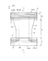
- FIG. 2 is a schematic plan view of the disposable diaper 10 according to this embodiment.
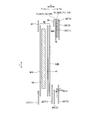
- FIG. 3 is a sectional view taken along the line AA shown in FIG.
- FIGS. 2 and 3 show an expanded state in which the absorbent article 10 is expanded to a state in which wrinkles are not formed in a state in which the side joint portion 60 described later is expanded.
- the respective members are shown separated in the thickness direction T for convenience of description, but they are in contact with each other in the thickness direction T in an actual product.
- the absorbent article 10 has a front-back direction L and a width direction W that are orthogonal to each other.
- the front-rear direction L is defined by the direction extending to the front side of the body and the back side of the body.
- the front-back direction L is a direction extending in the front-back direction in the expanded absorbent article 10.
- the absorbent article 10 has the thickness directions orthogonal to both the front-rear direction L and the width direction W.
- the absorbent article 10 has a front waistline region S1, a back waistline region S2, and a crotch region S3.
- the front waistline region S1 is a region facing the front waistline (abdomen) of the wearer.
- the rear waistline region S2 is a region facing the rear waistline (back part) of the wearer.
- the crotch region S3 is a region located at the crotch of the wearer and arranged between the front waistline region S1 and the rear waistline region S2.
- the crotch region S3 is a region in which leg openings 66 (see FIG. 1) described later are formed.
- the boundary on the crotch region side of the front waistline region S1 is the front end edge of the leg waist opening 66
- the boundary on the crotch region side of the rear waistline region S2 is the rear end edge of the leg waist opening 66.
- the absorbent article 10 may include an absorbent main body 40 and a waist belt 15.
- the waist belt 15 overlaps the absorbent main body 40 in the thickness direction.
- the waist belt 15 may include a front waist belt 20 and a rear waist belt 30.
- the front waist belt 20 is arranged in a region that overlaps the absorbent main body 40 and a region that does not overlap the absorbent main body 40 in the front waistline region S1.
- the rear waist belt 30 is separated from the front waist belt 20 in the front-rear direction L.
- the rear waist belt 30 is arranged in a region that overlaps with the absorbent main body 40 and a region that does not overlap with the absorbent main body 40 in the rear waistline region S2.
- the front waist belt 20 and the rear waist belt 30 may be integrated, and the waist belt 15 may be provided from the front waistline region S1 to the rear waistline region S2.
- the front waist belt 20 includes a front cover sheet 27 arranged on the skin surface side T1 of the absorbent main body 40 and a front first outer cover arranged on the non-skin surface side T2 of the absorbent main body 40.
- the front cover sheet 27, the front first exterior sheet 25, the exterior stretch sheet 28, and the front second exterior sheet 26 are sequentially laminated from the skin surface side T1 toward the non-skin surface side T2. , Joined to each other.
- the front cover sheet 27, the front first exterior sheet 25, and the front second exterior sheet 26 may be formed of separate sheets, or may be formed of the same folded sheet.
- the front cover sheet 27, the front first exterior sheet 25, the front second exterior sheet 26, and the exterior stretch sheet 28 may constitute the composite sheet 70 of the present invention.
- the front cover sheet 27 and the front first exterior sheet 25 constitute a first sheet 71 of the present invention
- the front second exterior sheet 26 constitutes a second sheet 72 of the present invention
- the exterior elastic sheet 28 is a book.
- the stretchable member 73 of the invention may be configured.
- the composite sheet 70 will be described in detail later.
- the rear waist belt 30 includes a rear cover sheet 37 arranged on the skin surface side T1 of the absorbent main body 40 and a rear first exterior member arranged on the non-skin surface side T2 of the absorbent main body 40.
- the rear cover sheet 37, the rear first exterior sheet 35, the rear thread rubber 38, and the rear second exterior sheet 36 are sequentially laminated from the skin surface side T1 toward the non-skin surface side T2. And may be joined together.
- the rear third exterior sheet 39 may be arranged on the skin side of the rear first exterior sheet 35.
- the rear cover sheet 37, the rear third exterior sheet 39, the rear first exterior sheet 35, the rear thread rubber 38, and the rear second exterior sheet 36 are from the skin surface side T1.
- the layers may be sequentially stacked toward the non-skin surface side T2 and bonded to each other.
- the rear cover sheet 37, the rear first exterior sheet 35, the rear second exterior sheet 36, and the rear third exterior sheet 39 may be separate sheets, or may be the same folded sheet. May be In the present embodiment, the rear second exterior sheet 36 and the rear third exterior sheet 39 are made of the same sheet folded at the waistline opening 62.
- the rear first exterior sheet 35, the rear second exterior sheet 36, and the rear thread rubber 38 may form the composite sheet 70 of the present invention.
- the rear first exterior sheet 35 constitutes the first sheet 71 of the present invention
- the front second exterior sheet 26 constitutes the second sheet 72 of the present invention
- the rear thread rubber 38 is the stretchable material of the present invention.
- the member 73 may be configured.
- a side joint 60 may be provided that joins the end of the front waistline region S1 in the width direction W and the end of the rear waistline region S2 in the width direction W.
- the side joint portion 60 is defined by a portion in which an end portion of the front waistline region S1 in the width direction W and an end portion of the rear waistline region S2 in the width direction W are locked to each other.
- the outer portion in the present invention is a portion that occupies a certain range in the width direction W including the outer edge in the width direction W, and the outer edge is the outer edge in the width direction W.
- the inner portion in the present invention is a portion that occupies a certain range in the width direction W including the inner edge in the width direction W, and the inner edge is the inner edge in the width direction W.
- the front end portion and the rear end portion in the present invention are portions that occupy a certain range in the front-rear direction L including the edges in the front-rear direction L, and the front end edge and the rear end edge are edges in the front-rear direction L.
- the outer end portion includes a front end portion and a rear end portion, and the outer end edge includes a front end edge and a rear end edge.
- the absorbent article 10 has a waistline opening 62 through which the wearer's torso passes and a pair of legs into which the wearer's legs are inserted.
- the leg openings 66 are formed.
- the waistline opening 62 may be defined by a front edge S1F of the front waistline region S1 and a rear edge S2R of the rear waistline region S2.
- FIG. 2 shows a state in which the joining at the side joining portion 60 is released and the absorbent article 10 is expanded.
- the side joint portion 60 may extend along the front-rear direction L in each of the front waist belt 20 and the rear waist belt 30.
- the boundary between the front waistline region S1 and the crotch region S3 may be defined by the rear end edge of the side joint portion 60 provided on the front waist belt 20.
- the boundary between the rear waistline region S2 and the crotch region S3 may be defined by the front end edge of the side joint portion 60 provided on the rear waist belt 30.
- a stretchable member that can stretch in the width direction W may be arranged in the front waistline region S1.
- the elastic member may be composed of at least one of the front side thread rubber 22 that can expand and contract in the width direction W and the exterior elastic sheet 28 that can expand and contract in the width direction W.
- the stretchable member may be configured by the front waist belt 20 itself configured by a stretchable sheet, for example.
- An elastic member that can expand and contract in the width direction W may be arranged in the rear waistline region S2.
- the stretchable member may be configured by at least one of the rear thread rubber 38 that is stretchable in the width direction W and the exterior stretchable sheet that is stretchable in the width direction W.
- the stretchable member may be configured by the rear waist belt 30 itself which is configured by a stretchable sheet, for example.
- the absorbent main body 40 is arranged so as to straddle the front waist belt 20 and the rear waist belt 30. That is, the absorbent main body 40 extends over the front waistline region S1, the rear waistline region S2, and the crotch region S3.
- the absorbent body 40 may be configured separately from the front waist belt 20 and the rear waist belt 30. In this case, the absorbent main body 40 may be joined to the front waist belt 20 and the rear waist belt 30 in the front waist region S1 and the back waist region S2, respectively.
- the absorbent body 40 includes at least an absorbent core 50.
- the absorbent core 50 may include, for example, ground pulp or super absorbent polymer (SAP), or a mixture thereof.
- the absorbent core 50 is arranged at least in the crotch region S3.
- the absorbent core 50 may extend in the front-rear direction L from the front waistline region S1 to the rear waistline region S2.
- the absorbent core 50 may be covered by a core wrap.
- the absorbent main body 40 includes a skin surface sheet 42A arranged on the skin surface side of the absorbent core, and a liquid impermeable sheet 41 arranged on the non-skin surface side of the absorbent core 50.
- the main body sheet 42B arranged on the non-skin surface side T2 with respect to the liquid impermeable sheet 41 may be included.
- the skin surface sheet 42A, the liquid impermeable sheet 41, and the main body sheet 42B are arranged in this order from the skin surface side T1 to the non-skin surface side T2. It is located at. In the region overlapping with the absorbent core 50, the skin surface sheet 42A, the absorbent core 50, the liquid impermeable sheet 41, and the main body sheet 42B are arranged in this order from the skin surface side T1 to the non-skin surface side T2. ..
- the skin surface sheet 42A and the liquid impermeable sheet 41 may be arranged so as to sandwich the absorbent core 50 in the thickness direction T.
- the liquid-impermeable sheet 41 may be liquid-impermeable and may be formed of, for example, a film.
- the skin sheet 42A and the main body sheet 42B may be liquid-permeable and may be made of, for example, a nonwoven fabric.
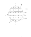
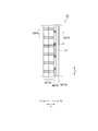
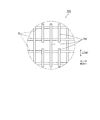
- FIG. 4 is a plan view of the composite sheet in the portion B shown in FIG. 2, and FIG. 5 is a cross-sectional view taken along the line CC shown in FIG. 4 and 5 show the composite sheet in the stretched state. 4 and 5, the composite sheet in the portion B is shown, and the rear cover sheet 37 and the rear third exterior sheet 39 among the members constituting the rear waist belt 30 are omitted.
- the composite sheet of the rear waist belt will be described.
- the front waist belt 20 may also have the composite sheet, and the configuration of the composite sheet in the rear waist belt is applicable to the composite sheet in the front waist belt 20.
- the composite sheet 70 includes a first sheet 71 having a laminated body 76 in which two or more layers are laminated, a second sheet 72 arranged so as to overlap the first sheet 71, a first sheet 71 and a second sheet 72. And a stretchable member 73 that is disposed between and that stretches in the first direction D1.
- the rear first exterior sheet 35 constitutes the first sheet 71
- the rear second exterior sheet 36 constitutes the second sheet 72
- the rear thread rubber 38 constitutes the elastic member 73. doing.
- the rear first exterior sheet 35 as the first sheet 71 has a laminated body 76 in which two or more layers are laminated.
- the sheet forming the first sheet 71 is not limited, but may be, for example, a nonwoven fabric.
- the rear first exterior sheet 35 may be composed of only the laminated body 76 or may include other sheets.
- the laminate 76 may have three or more layers as long as the same or different sheets are overlapped.
- the first sheet 71 may be provided with a joining portion 75 that joins the sheets forming the laminated body 76.
- the joining portion 75 may be provided so as not to reach the second sheet 72, may be provided over the entire area in the thickness direction T of the first sheet 71, or may be provided in one portion of the thickness direction T of the first sheet 71. It may be provided in the section.
- examples include a welded portion formed by welding the sheets forming the first sheet 71 by heat or ultrasonic waves, an embossed portion formed by compressing the sheets in the thickness direction, and an adhesive portion formed by joining the sheets with an adhesive.
- a plurality of the joint portions 75 are provided at intervals in a plan view. That is, the joint portions 75 are arranged at intervals in at least one of the front-rear direction L and the width direction.
- the rear thread rubber 38 as a stretchable member is configured to be stretchable in the width direction W as the first direction.
- the rear side rubber thread 38 is stretched in the width direction and is located between the rear first exterior sheet 35 (first sheet 71) and the rear second exterior sheet 36 (second sheet 72). 35 and the second rear exterior sheet 36.
- the fixing means of the rear side thread rubber 38 is not limited, but for example, an adhesive can be used.
- the stretchable member 73 may be made of rubber thread, or may be in the form of a sheet like the exterior stretchable sheet 28.
- the rear side thread rubber 38 of the embodiment is formed of a plurality of thread rubbers, and is arranged at intervals in the second direction D2 (front-rear direction L) orthogonal to the first direction D1.
- the rear second exterior sheet 36 as the second sheet 72 covers the stretchable member 73.
- the first sheet 71 is arranged on one side of the elastic member 73 in the thickness direction T, and the second sheet 72 is arranged on the other side.
- the sheet forming the second sheet 72 is not limited, but may be, for example, a non-woven fabric.
- the second sheet 72 does not have the joining portion 75 formed on the first sheet 71, and is joined to the first sheet 71 and/or the elastic member 73 by a joining means different from the joining portion 75. ..
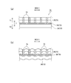
- FIG. 6 is a diagram for explaining a modified mode of the composite sheet 70, which is based on the cross section taken along the line DD of FIG.
- FIG. 6A shows an expanded state
- FIG. 6B shows a contracted state in which the elastic member contracts.
- the contraction of the elastic member 73 causes the first sheet 71 and the second sheet 72 to contract in the first direction D1. Due to the contraction of the elastic member 73, the region between the joint portions 75 of the first sheet 71 is deformed so as to expand in the thickness direction T, and the folds formed of the first sheet 71 can be formed between the adjacent joint portions 75.
- the contraction of the stretchable member also contracts the second sheet 72, and the folds are formed on the second sheet 72. Therefore, the folds are formed on the surface of the composite sheet 70, and the cushioning property is improved. Further, since the joint portion of the first sheet 71 is not formed on the second sheet, the folds formed on the first sheet 71 and the folds formed on the second sheet are formed at different positions and modes. It The cushioning property is further enhanced as compared with the configuration in which the folds formed on the first sheet 71 and the folds formed on the second sheet are integrated.
- the composite sheet 70 may have a contact area 77 where the first sheet 71 and the second sheet 72 contact.
- the contact region 77 is a region in which other members are not arranged between the first sheet 71 and the second sheet 72 in a region that does not overlap the elastic member 73. In FIG. 5, the contact area 77 is shown. Since no sheets other than the stretchable member 73 are arranged between the first sheet 71 and the second sheet 72, the contracting force of the stretchable member 73 is greater than that in the case where members other than the stretchable member are arranged. Is easily transmitted, and the cushioning property of the composite sheet 70 can be further enhanced.
- a fold line FL76 obtained by folding a sheet forming the laminated body 76 may be provided on an edge of the laminated body 76.
- the number of parts can be reduced as compared with the laminated body 76 in which separate sheets are laminated.
- the positional deviation of the laminated sheets does not occur.
- the positional deviation of the sheets forming the laminated body 76 is suppressed, and the accuracy of the absorbent article 10 can be improved.
- a gap is easily formed between the sheets, the cushioning property of the laminate 76 is improved, and the cushioning property of the composite sheet 70 can be further improved.
- the method of joining the sheets forming the laminate 76 is not limited, and examples thereof include welding by heat or ultrasonic waves, embossing, and an adhesive.
- the joining of the sheets forming the laminate and the joining of the first sheet 71 and the second sheet 72 may be joined by an adhesive.
- the basis weight of the adhesive that bonds the laminate may be lower than the basis weight of the adhesive that bonds the first sheet 71 and the second sheet 72. Since the basis weight of the adhesive provided between the first sheet 71 and the second sheet 72 is high, the bonding strength of the elastic member 73 to the first sheet 71 and the second sheet 72 is high, and the elastic member 73 contracts. Is easily transmitted to the first sheet 71 and the second sheet 72.
- the basis weight of the adhesive of the laminated body 76 is low, the sheets forming the laminated body 76 are easily deformed flexibly, and the folds are easily formed on the laminated body 76. Therefore, the cushioning property of the laminated body 76 is improved, and the cushioning property of the composite sheet 70 obtained by the manufacturing method can be improved.
- a plurality of elastic members 73 are provided at intervals in a second direction D2 that is orthogonal to the first direction D1 that is the expansion/contraction direction, and the joint portions 75 are provided at intervals in the second direction D2. Multiple may be provided.
- the pitch D275 of the joint portions 75 in the second direction D2 may be shorter than the pitch D273 of the elastic members 73 in the second direction D2. Since the plurality of joint portions 75 are arranged at intervals in the second direction D2, the folds extending in the second direction D2 can be formed. Further, since the pitch of the joint portions 75 is short, it is possible to form finer folds.
- the composite sheet 70 has a cushioning property, and it is particularly preferable to dispose the composite sheet 70 in a region where the touch is desired to be improved.
- the composite sheet 70 is arranged on the front waist belt 20 and the rear waist belt 30. By providing the waist belt 15 including the composite sheet 70 having high cushioning properties, the feel of the waist can be improved.
- the composite sheet may be arranged on the leg flaps arranged along the circumference of the wearer's legs. According to the modified example, the feel of the wearer around the legs can be improved.
- the first sheet 71 of the composite sheet may be located closer to the skin surface side T1 than the second sheet 72.
- the cushioning property of the side that comes into contact with the skin can be improved, and the feel of the wearer can be improved.
- the first sheet 71 of the composite sheet 70 may be provided on the most skin-side surface of the absorbent article 10, that is, the surface that directly contacts the wearer. With such a configuration, the feel of the wearer can be improved.
- the front cover sheet 27 forming the first sheet 71 in the front waist belt 20 is provided on the surface that directly contacts the wearer.
- the first sheet 71 and the second sheet 72 are made of a non-woven fabric or a woven fabric having fibers, and the basis weight of the fibers of the first sheet 71 may be higher than the basis weight of the fibers of the second sheet 72. Since the basis weight of the first sheet 71 is high, the folds formed on the first sheet 71 are less likely to be crushed and the wrinkles are easily maintained. Therefore, the cushioning property of the first sheet 71 is further improved, and the touch can be improved. Further, in a modified example, the basis weight of the fibers of the first sheet 71 may be lower than the basis weight of the fibers of the second sheet 72. Since the basis weight of the first sheet is relatively low, the first sheet is likely to be deformed and folds are easily formed on the first sheet. Therefore, the cushioning property of the first sheet 71 is further improved, and the touch can be improved.
- a first fold FL71 in which the sheet is folded may be provided on the outer edge of the first sheet 71 in the front-rear direction L along the width direction.
- the first fold FL71 may be arranged outside the front-rear outer edge of the absorbent main body in the front-rear direction.
- the rear first exterior sheet 35 is provided with a fold line FL76 in which the sheets forming the laminated body are folded.
- the fold line FL76 constitutes the first fold line FL71.
- the first fold FL71 is located at the rear edge 71R of the first sheet 71 and extends along the width direction W.
- the first fold FL71 is separated from the rear end edge 40R of the absorbent main body 40 and is located rearward of the rear end edge 40R of the absorbent main body 40.
- a gap is likely to be formed between the sheets folded down via the first fold FL71, and the thickness of the first sheet 71 is likely to be thick.
- a region outside the outer edge of the absorbent main body 40 in the front-rear direction is more likely to have a thickness difference with respect to the thickness than the region in which the absorbent main body is arranged. It can be filled by the thickness of the region near the fold. Therefore, the difference in thickness of the waist belt is reduced, and the touch can be improved.
- the outer edge of the second sheet 72 in the front-rear direction may be provided with a second fold FL72 in which the second sheet 72 is folded along the width direction.
- the second fold FL72 may be arranged outside the outer edge of the absorbent main body 40 in the front-rear direction L in the front-rear direction.
- the outer side in the front-rear direction of the absorbent body 40 in the front-rear direction L is an area between the rear edge 40R of the absorbent body 40 and the rear edge 10R of the absorbent article, and the absorbent body 40. It is a region between the front edge 40F and the front edge 10F of the absorbent article.
- the rear second exterior sheet 36 is folded back and forth at the fold line FL36.
- the folded portion constitutes the rear third exterior sheet 39.
- the fold FL36 of the rear second exterior sheet 36 constitutes a second fold FL72.
- the second fold FL72 is located at the rear edge of the second sheet 72 and extends along the width direction W.
- the second fold line FL72 is separated from the rear end edge 40R of the absorbent main body 40 and is located rearward of the rear end edge 40R of the absorbent main body 40.
- the rear edge 72R of the second sheet 72 constitutes the rear edge of the composite sheet 70 and may be located at the rear edge of the rear waist belt 30.
- a region outside the outer edge of the absorbent main body 40 in the front-rear direction L is more likely to have a thickness difference with respect to the thickness than the region in which the absorbent main body 40 is arranged. It can be further filled by the thickness of the region near the second fold.
- the first fold of the first sheet 71 may be arranged between the second sheets 72 folded via the second fold FL 72.
- the first fold FL71 is arranged between the rear second exterior sheet 36 and the rear third exterior sheet 39. Since the first fold of the first sheet 71 is arranged between the second sheets 72 folded through the second fold FL72, the second fold FL72 is overlapped with the bulge of the sheet near the first fold FL71. A bulge in the vicinity of can be provided. The difference in the thickness of the waist belt is reduced, and the touch can be improved.
- the composite sheet manufacturing method S100 may include a first sheet forming step S11, a second sheet conveying step S21, an adhesive applying step S31, and a stretchable member arranging step S41.
- the first sheet forming step S11 the first continuous sheet body C71 is formed by using the continuous laminated body C76 in which continuous sheets are stacked in the transport direction MD.
- the stacked continuous body C76 is formed by stacking two or more sheets and is continuous in the transport direction MD.
- a plurality of joint portions 75 are formed on the continuous laminate C76 at intervals in a plan view.
- the joining portions 75 may be arranged at intervals in a plan view, may be arranged at intervals in the transport direction MD, or may be spaced in the orthogonal direction CD orthogonal to the transport direction MD. They may be arranged, or may be arranged at intervals in the transport direction MD and the orthogonal direction CD.
- the second sheet carrying step S21 carries the second sheet continuum C72 continuous in the carrying direction MD.
- an adhesive for adhering the stretchable member 73 provided between the first sheet continuum C71 and the second sheet continuum C72 is used for the first sheet continuum C71 and the second sheet continuum. It is given to at least one of C72 and the elastic member.
- the order of the first sheet forming step S11, the second sheet conveying step S21, and the adhesive applying step S31 is not limited as long as the adhesive applying step S31 is performed after the first sheet forming step S11.
- the elastic member arranging step S41 is performed after the first sheet forming step S11, the second sheet conveying step S21, and the adhesive applying step S31, and between the first sheet continuous body C71 and the second sheet continuous body C72.
- the stretchable member 73 in the stretched state is bonded via an adhesive.
- the expansion/contraction direction of the elastic member 73 is not limited, but may be preferably along the transport direction MD. Since the stretchable direction of the stretchable member 73 is along the transport direction MD of the first continuous sheet C71 and the second continuous sheet C72, the manufacturing process and equipment can be simplified.
- the stretchable member in the stretched state is bonded between the first sheet continuum C71 and the second sheet continuum C72, and the first sheet continuum is contracted by contraction of the stretchable member.
- the body C71 and the second sheet continuous body C72 contract. Due to the contraction of the elastic member, the region between the joints of the first sheet is deformed so as to expand in the thickness direction, and the folds of the first sheet can be formed between the adjacent joints. In addition, a fold is formed on the second sheet due to the contraction of the elastic member. Therefore, the composite sheet obtained by the manufacturing method has folds formed on its surface, and the cushioning property is enhanced.
- the stretchability of the stretchable member is not hindered due to the step of forming the joint portion 75. Therefore, there are less restrictions on the arrangement of the joint and the elastic member, and the degree of freedom of arrangement of the joint and the elastic member can be improved.
- a fold can be formed in an intended shape in an intended position, and a composite sheet having a desired cushioning property can be obtained.
- the first sheet forming step S11 may form the joint portions 75 at intervals in the transport direction MD, and the elastic member arranging step S41 may bond the elastic member 73 stretched in the transport direction MD.
- the joint portions 75 of the first sheet continuum C71 may be provided at intervals in the transport direction MD, folds depending on the presence or absence of the joint portions 75 can be alternately formed in the transport direction MD.
- the elastic member 73 contracts in the transport direction MD, the folds of the first sheet continuum C71 can be formed more finely.
- the joint portion 75 extending in the orthogonal direction CD is formed in a region straddling the plurality of elastic members 73 arranged at intervals in the orthogonal direction CD orthogonal to the transport direction MD. May be formed.
- FIG. 8 is a plan view of the composite sheet 70X manufactured by the manufacturing method according to the modification.
- the joint portion 75X according to the modified example is provided so as to straddle the stretchable members arranged at intervals in the orthogonal direction. Therefore, the folds extending in the orthogonal direction can be formed by contraction of the plurality of elastic members, the precision of the folds can be improved, and the shape of the folds can be easily maintained.
- the joining means of the joining portion 75 in the first sheet forming step S11 is not particularly limited.
- the joint may be formed by ultrasonic welding or embossing.
- the ultrasonic welding and embossing can form the joint portion 75 while conveying the laminated continuous body C76 at high speed.
- the degree of freedom in arranging the joint portion 75 is high, and the degree of freedom in design and the accuracy of the position of the folds can be improved.
- an adhesive may be applied by coater coating to form a joint.
- the coater coating is a contact coating, and the adhesive can be arranged on the surface as compared with a non-contact coating method.
- the area to which the adhesive is applied by the coater coating has high rigidity due to the adhesive.
- the elastic member 73 may be applied with an adhesive.
- the adhesive does not easily exude to the outer surface of the composite sheet 70, and the adhesive adheres to the transport path of the composite sheet 70 Can be suppressed. Further, the adhesive hardly leaks to the surface of the composite sheet 70 obtained by the manufacturing method, and the touch of the absorbent article 10 having the composite sheet 70 can be improved.
- the first sheet continuum C71 and the second sheet continuous body C72 may be brought into contact with each other in a region that does not overlap the elastic member 73 in the thickness direction T. That is, no sheet or the like other than the stretchable member 73 is arranged between the first continuous sheet C71 and the second continuous sheet C72. Compared to the configuration in which members other than the elastic member are arranged, the contracting force of the elastic member 73 is easily transmitted, and the cushioning property of the composite sheet 70 can be further enhanced.
- the composite sheet manufacturing method may include a laminated body forming step S51 before the first sheet forming step S11.
- a sheet continuous in the transport direction MD is folded around a fold line along the transport direction MD as a base point to form a continuous laminate C76.
- the laminated continuous body formed by folding the sheets has a fold line at one end in the orthogonal direction, and at the one end, the positional deviation of the laminated sheets in the orthogonal direction does not occur.
- the laminated continuum C76 may be formed so that the folded sheets can be separated from each other.
- the laminated continuum C76 may be formed without providing an adhesive between the folded sheets.
- a gap is easily formed between the sheets forming the laminated continuous body C76, the cushioning property of the laminated continuous body C76 is improved, and the cushioning property of the composite sheet obtained by the manufacturing method can be further improved.
- the region where the folded sheets can be separated from each other may be a part of the continuous laminate.
- the folded sheets may be joined together via an adhesive.
- the sheets forming the laminated continuum are joined together via an adhesive having a grammage lower than that of the adhesive provided between the first sheet continuum C71 and the second sheet continuum C72.
- You can A gap is easily formed between the sheets that form the laminated continuum C76, the cushioning properties of the laminated continuum C76 are improved, and the cushioning properties of the composite sheet obtained by the manufacturing method can be further improved. Further, the material cost of the adhesive can be reduced, and the manufacturing process can be simplified.
- the thread-shaped or strip-shaped elastic members 73 may be arranged at intervals in the orthogonal direction CD.
- the stretchability of the stretchable member 73 is not hindered due to the step of forming the joint portion 75, and the degree of freedom in disposing the stretchable member 73 can be increased.
- By increasing the degree of freedom of arrangement of the elastic member it is possible to form a fold in an intended shape at an intended position and obtain a composite sheet having a desired cushioning property.
- the method of manufacturing the absorbent article includes a belt forming step of forming a waist belt using the composite sheet 70 obtained by the method of manufacturing the composite sheet 70.
- the second sheet 72 is folded back with the second fold FL72 as a base point to form the rear third exterior sheet 39. Then, the rear cover sheet 37 is arranged with the absorbent main body 40 interposed therebetween.
- the first belt continuum C71 side of the composite sheet may be arranged on the skin surface side of the absorbent article to form the waist belt 15. The cushioning property of the side that comes into contact with the skin can be improved, and the feel of the wearer can be improved. More preferably, the waist belt 15 may be formed so that the first sheet 71 of the composite sheet 70 is located on the most skin-side surface of the absorbent article. With such a configuration, the feel of the wearer can be improved.
- the waist belt 15 may be formed by arranging the second sheet continuum C72 side of the composite sheet 70 on the skin side of the absorbent article. It is possible to improve the touch when the absorbent article 10 is touched from the outside, and it is possible to enhance the sense of security when the wearer touches the absorbent article 10 from the outside. More preferably in the modified example, the waist belt 15 may be formed so that the first sheet 71 of the composite sheet 70 is located on the most non-skin side surface of the absorbent article. With such a configuration, the touch of the absorbent article when touched from the outside can be further improved.
- the method for manufacturing an absorbent article may include an absorbent main body forming step and a belt joining step.
- the absorbent main body forming step includes an absorbent core having a scavenging material, a skin side sheet arranged on the skin side of the absorption core, and a non-skin side sheet arranged on the non-skin side of the absorption core. Laminate to form the absorbent body.
- the belt joining step joins the absorbent main body obtained by the absorbent main body forming step and the waist belt obtained by the belt forming step.
Landscapes
- Health & Medical Sciences (AREA)
- Engineering & Computer Science (AREA)
- Life Sciences & Earth Sciences (AREA)
- Heart & Thoracic Surgery (AREA)
- Epidemiology (AREA)
- Biomedical Technology (AREA)
- Vascular Medicine (AREA)
- Animal Behavior & Ethology (AREA)
- General Health & Medical Sciences (AREA)
- Public Health (AREA)
- Veterinary Medicine (AREA)
- Wood Science & Technology (AREA)
- Absorbent Articles And Supports Therefor (AREA)
- Application Of Or Painting With Fluid Materials (AREA)
- Laminated Bodies (AREA)
Abstract
複合シートにおける接合部と伸縮性部材の配置の自由度を向上させ、高いクッション性を有する複合シートを得る。複合シートの製造方法(S100)は、搬送方向に連続するシートが積層された積層連続体(C76)を用いて第1シート連続体(C71)を形成する第1シート形成工程(S11)と、第2シート連続体(C72)を搬送する第2シート搬送工程(S21)と、第1シート連続体と第2シート連続体の間に設けられる伸縮性部材(73)を接着するための接着剤を、第1シート連続体、第2シート連続体及び伸縮性部材の少なくともいずれかに付与する接着剤付与工程(S31)と、第1シート連続体と第2シート連続体の間に、接着剤を介して伸長状態の伸縮性部材を接着する伸縮性部材配置工程(S41)と、を有する。第1シート形成工程は、平面視にて間隔を空けて複数の接合部を積層連続体に形成する。
Description
本発明は、吸収性物品等に用いられる複合シート及び複合シートの製造方法、複合シートを有する吸収性物品及び吸収性物品の製造方法に関する。
特許文献1には、吸収性物品のウエストベルトを構成する複合シートが開示されている。特許文献1の複合シートは、内層シートと、内層シートと積層された外層シートと、内層シートと外層シートの間に配置された糸状の伸縮性部材と、内層シートと外層シートを接合した接合部と、を有している。伸縮性部材は、幅方向に延び、かつ前後方向に間隔を空けて複数配置されている。接合部は、幅方向及び前後方向に間隔を空けて複数配置されている。伸縮性部材が収縮することにより、隣り合う接合部間のシートが、それぞれ厚み方向に膨らむように変形して、隣接する接合部間にシートからなる襞が形成でされる。
特許文献1の複合シートの接合部は、熱溶着によって内層シートと外層シートを接合している。このように構成された複合シートを製造するためには、内層シートと外層シートの間に伸縮性部材を配置し、その後に熱溶着によって接合部を形成する。例えば、伸縮性部材に重なるように接合部を形成すると、熱溶着による接合部を形成する過程に起因して伸縮性部材の伸縮性が阻害されるおそれがある。そのため、伸縮性部材と重ならない領域に接合部を形成しなければならず、接合部及び伸縮性部材の配置が制限され、意図した位置に意図した形状で襞を形成できず、所望のクッション性を有する複合シートを得ることができなかった。そこで、複合シートにおける接合部と伸縮性部材の配置の自由度を向上させ、高いクッション性を有する複合シートを得ることを目的とする。
一態様に係る複合シートの製造方法は、搬送方向に連続するシートが積層された積層連続体を用いて第1シート連続体を形成する第1シート形成工程と、搬送方向に連続する第2シート連続体を搬送する第2シート搬送工程と、前記第1シート連続体と前記第2シート連続体の間に設けられる伸縮性部材を接着するための接着剤を、前記第1シート連続体、前記第2シート連続体及び前記伸縮性部材の少なくともいずれかに付与する接着剤付与工程と、前記第1シート連続体と前記第2シート連続体の間に、前記接着剤を介して伸長状態の前記伸縮性部材を接着する伸縮性部材配置工程と、を有し、前記第1シート形成工程は、平面視にて間隔を空けて複数の接合部を前記積層連続体に形成する。
一態様に係る吸収性物品の製造方法は、前胴回り域、股下域及び後胴回り域を有する吸収性物品の製造方法であって、複合シートの製造方法によって得られる複合シートを用いて、前記前胴回り域及び前記後胴回り域の少なくともいずれか一方に配置されるウエストベルトを形成するベルト形成工程を有する。
一態様に係る複合シートは、2層以上のシートが積層された積層体を有する第1シートと、前記第1シートと重ねて配置された第2シートと、前記第1シートと前記第2シートの間に配置され、かつ第1方向に伸縮する伸縮性部材と、を有する複合シートであって、前記積層体を構成するシートを接合する接合部が前記第2シートに到達しないように前記第1シート内に設けられており、前記接合部は、平面視にて間隔を空けて複数設けられている。
一態様に係る吸収性物品は、前後方向及び前記前後方向に直交する幅方向と、前胴回り域と、後胴回り域と、前記前胴回り域と前記後胴回り域との間に配置された股下域と、前記股下域、前記前胴回り域及び前記後胴回り域に跨がって配置された吸収性本体と、前記前胴回り域及び前記後胴回り域の少なくともいずれか一方において前記吸収性本体の非肌面側に配置されたウエストベルトと、を有する吸収性物品であって、前記ウエストベルトは、複合シートを有する。
(1)実施形態の概要
本明細書及び添付図面の記載により、少なくとも以下の事項が明らかとなる。
一態様に係る複合シートの製造方法は、搬送方向に連続するシートが積層された積層連続体を用いて第1シート連続体を形成する第1シート形成工程と、前記搬送方向に連続する第2シート連続体を搬送する第2シート搬送工程と、前記第1シート連続体と前記第2シート連続体の間に設けられる伸縮性部材を接着するための接着剤を、前記第1シート連続体、前記第2シート連続体及び前記伸縮性部材の少なくともいずれかに付与する接着剤付与工程と、前記第1シート連続体と前記第2シート連続体の間に、前記接着剤を介して伸長状態の前記伸縮性部材を接着する伸縮性部材配置工程と、を有し、前記第1シート形成工程は、平面視にて間隔を空けて複数の接合部を前記積層連続体に形成する。伸縮性部材の収縮によって第1シート連続体と第2シート連続体が収縮する。この伸縮性部材の収縮により、第1シート連続体における接合部間の領域が厚み方向に膨らむように変形して、隣接する接合部間に第1シート連続体からなる襞を形成できる。加えて、第2シートには、伸縮性部材の収縮によって襞が形成される。よって、当該製造方法によって得られた複合シートは、その表面に襞が形成され、クッション性が高まる。よって、接合部と伸縮性部材によって高いクッション性を有する複合シートを得ることができる。また、接合部が形成された第1シート連続体と伸縮性部材を接着するため、接合部の形成工程に起因して伸縮性部材の伸縮性が阻害されることがない。よって、接合部及び伸縮性部材の配置の制限が少なくなり、接合部と伸縮性部材の配置の自由度を向上させることができる。意図した位置に意図した形状で襞を形成でき、所望のクッション性を有する複合シートを得ることができる。
好ましい一態様によれば、前記第1シート形成工程は、前記搬送方向に間隔を空けて前記接合部を形成し、前記伸縮性部材配置工程は、前記搬送方向に伸長させた前記伸縮性部材を接着してよい。搬送方向に間隔を空けて接合部を設けることにより、接合部の有無による襞を搬送方向に交互に形成できる。加えて、伸縮性部材が搬送方向に収縮するため、第1シート連続体の襞がより細かく形成される。
好ましい一態様によれば、前記第1シート形成工程は、前記搬送方向と直交する直交方向に間隔を空けて配置された複数の伸縮性部材を跨がる領域に、前記直交方向に延びる接合部を形成してよい。直交方向に間隔を空けて配置された伸縮性部材を跨がって接合部を設けることにより、接合部による襞が直交方向に延びる。襞を複数の伸縮性部材の収縮によって形成でき、襞の精度を向上できるとともに襞の形状を維持し易くなる。
好ましい一態様によれば、前記第1シート形成工程は、超音波溶着又はエンボス加工によって前記接合部を形成してよい。超音波溶着及びエンボス加工は、高速で積層連続体を搬送しつつ接合部を形成できる。また、接合部の配置の自由度が比較的高く、より意図した位置に意図した形状で襞を形成できる。
他の形態によれば、前記第1シート形成工程は、コーター塗工によって接着剤を塗布し、前記接合部を形成してよい。コーター塗工によって接着剤が塗布された領域は、接着剤によって剛性が高くなる。第1シートの剛性が高くなることにより、第1シートのたくれが抑制され、意図した襞を形成し易くなる。
好ましい一態様によれば、前記接着剤付与工程は、前記伸縮性部材に前記接着剤を塗布してよい。第1シート連続体及び第2シート連続体に接着剤を塗布する形態と比較して、複合シートの外面に接着剤が滲み出し難く、複合シートの搬送経路に接着剤が付着することを抑制できる。また、当該製造方法によって得られた複合シートの表面に接着剤が滲み出しにくく、当該複合シートを有する吸収性物品の肌触りを向上できる。
好ましい一態様によれば、前記伸縮性部材配置工程は、厚み方向において前記伸縮性部材と重ならない領域で前記第1シート連続体と前記第2シート連続体を当接させてよい。本態様によれば、第1シート連続体及び第2シート連続体の間に伸縮性部材以外の部材が配置されていない領域が設けられる。伸縮性部材以外の部材が配置される形態と比較して、伸縮性部材による収縮力が第1シート連続体及び第2シート連続体に対して伝わり易い。よって、伸縮性部材の収縮によって襞を複合シートに形成し、高いクッション性を有する複合シートを得ることができる。
好ましい一態様によれば、前記搬送方向に連続するシートを、前記搬送方向に沿った折り線を基点に折り畳み、積層連続体を形成する積層体形成工程を有し、前記第1シート形成工程は、前記積層体形成工程の後に行われてよい。シートを折り畳んで積層連続体を形成することにより、別体のシートを積層して積層連続体を形成する構成と比較して、部品点数を低減でき、部品の管理工数を削減できる。また、シートが折り畳まれて形成された積層連続体は、直交方向の一端が折り目であり、当該一端においては、積層されたシートの直交方向の位置ズレが生じない。よって、別体のシートを積層して積層連続体を形成する構成と比較して、積層されたシートの直交方向の位置ずれを抑制できる。加えて、積層連続体を構成するシート間の空気が抜けにくく、シート間に隙間が形成され易く、積層連続体のクッション性が向上し、当該製造方法によって得られた複合シートのクッション性を更に向上できる。
好ましい一態様によれば、前記積層体形成工程は、前記折り畳まれたシート同士が離間可能に、前記積層連続体を形成してよい。積層連続体を構成するシート間に隙間が形成され易く、積層連続体のクッション性が向上し、当該製造方法によって得られた複合シートのクッション性を更に向上できる。
他の形態によれば、前記積層体形成工程は、前記第1シート連続体と前記第2シート連続体の間に設けられる接着剤の坪量よりも低い坪量の接着剤を介して前記積層連続体を構成するシート同士を接合してよい。第1シート連続体と第2シート連続体の間に設けられる接着剤の坪量が高いため、第1シート連続体及び第2シート連続体に対する伸縮性部材の接合強度が高くなり、伸縮性部材の収縮が第1シート連続体及び第2シート連続体に伝わり易くなる。また、積層連続体の接着剤の坪量が低いため、積層連続体を構成するシートが柔軟に変形し易く、積層連続体に襞を形成し易い。よって、積層連続体のクッション性が向上し、当該製造方法によって得られた複合シートのクッション性を向上できる。また、接着剤の資材コストを低減でき、製造工程を簡素化できる。
好ましい一態様によれば、前記伸縮性部材配置工程は、糸状又は帯状の前記伸縮性部材を、前記搬送方向と直交する直交方向に間隔を空けて配置してよい。接合部の形成工程に起因して伸縮性部材の伸縮性が阻害されることがなく、伸縮性部材73の配置の自由度を高めることができる。伸縮性部材の配置の自由度を向上させることにより、意図した位置に意図した形状で襞を形成でき、所望のクッション性を有する複合シートを得ることができる。
一態様に係る吸収性物品の製造方法は、前胴回り域、股下域及び後胴回り域を有する吸収性物品の製造方法であって、上述に記載の複合シートの製造方法によって得られる複合シートを用いて、前記前胴回り域及び前記後胴回り域の少なくともいずれか一方に配置されるウエストベルトを形成するベルト形成工程を有する。高いクッション性を有する複合シートを有するウエストベルトを備えることにより、腰周りに対する肌触りを向上できる。
好ましい一態様によれば、前記ベルト形成工程は、前記複合シートの前記第1シート連続体側を前記吸収性物品の肌面側に配置して、前記ウエストベルトを形成してよい。第1シート連続体側に襞をより形成し易いため、肌に触れる面側のクッション性を向上でき、着用者の肌触りを向上できる。
好ましい一態様によれば、前記ベルト形成工程は、前記複合シートの前記第2シート連続体側を前記吸収性物品の肌面側に配置して、前記ウエストベルトを形成してよい。第1シート連続体側に襞をより形成し易いため、吸収性物品を外側から触れた際の肌触りを向上できる。
好ましい一態様によれば、吸収材料を有する吸収コアと、前記吸収コアの肌面側に配置される肌面側シートと、前記吸収コアの非肌面側に配置される非肌面側シートと、を積層して吸収性本体を形成する吸収性本体形成工程と、前記吸収性本体形成工程によって得られる前記吸収性本体と、前記ベルト形成工程によって得られるウエストベルトと、を接合するベルト接合工程と、を有してよい。本態様によれば、ウエストベルトと吸収性本体を別々に製造することにより、それぞれを意図した仕様で安定して製造できる。高いクッション性を有する複合シートを有するウエストベルトを備えることにより、肌触りの優れた吸収性物品を得ることができる。
一態様に係る複合シートは、2層以上のシートが積層された積層体を有する第1シートと、前記第1シートと重ねて配置された第2シートと、前記第1シートと前記第2シートの間において前記第1シートと前記第2シートに接合され、かつ第1方向に伸縮する伸縮性部材と、を有する複合シートであって、前記積層体を構成するシートを接合する接合部が前記第2シートに到達しないように前記第1シート内に設けられており、前記接合部は、平面視にて間隔を空けて複数設けられている。複合シートは、伸縮性部材の収縮によって第1シートと第2シートが第1方向に収縮する。この伸縮性部材の収縮により、第1シートにおける接合部間の領域が厚み方向に膨らむように変形して、隣接する接合部間に第1シートからなる襞を形成できる。加えて、伸縮性部材の収縮によって第2シートも収縮し、第2シートに襞が形成される。よって、複合シートは、その表面に襞が形成され、クッション性が向上する。また、第1シートの接合部は、第2シートに形成されていないため、接合部の形成工程に起因して伸縮性部材の伸縮性が阻害されることがない。よって、接合部及び伸縮性部材の配置の制限が少なくなり、接合部と伸縮性部材の配置の自由度を向上させることができる。意図した位置に意図した形状で襞を形成でき、所望のクッション性を有する複合シートを得ることができる。また、第1シートの接合部は、第2シートに形成されていないため、第1シートに形成される襞と、第2シートに形成される襞と、が異なる位置及び態様で形成される。第1シートに形成される襞と第2シートに形成される襞が一体化した構成と比較して、よりクッション性が高まる。
好ましい一態様によれば、前記伸縮性部材は、前記第1方向と直交する第2方向に間隔を空けて複数設けられており、前記接合部は、前記複数の伸縮性部材を跨がって配置されてよい。複数の伸縮性部材を跨がって接合部を設けることにより、襞を複数の伸縮性部材の収縮によって形成でき、襞の精度を向上できるとともに襞の形状を維持し易くなる。
好ましい一態様によれば、前記第1シートと前記第2シートが当接する当接領域を有してよい。第1シート及び第2シートの間に伸縮性部材以外の部材が配置されていない領域が設けられる。伸縮性部材以外の部材が配置される形態と比較して、伸縮性部材による収縮力が第1シート及び第2シートに対して伝わり易い。よって、伸縮性部材の収縮によって襞を複合シートに形成し、高いクッション性を有する複合シートを得ることができる。
好ましい一態様によれば、前記積層体の端縁には、前記積層体を構成するシートを折り畳んだ折り目が設けられてよい。折り畳まれたシートによって積層体を構成することにより、別体のシートが積層された積層体と比較して、部品点数を低減できる。また、積層体の折り目が設けられた端縁では、積層されたシートの位置ズレが生じない。積層体を構成するシートの位置ズレが抑制され、吸収性物品の精度を向上できる。加えて、積層体を構成するシート間の空気が抜け難い。シート間に隙間が形成され易く、積層体のクッション性が向上し、複合シートのクッション性を更に向上できる。
好ましい一態様によれば、前記積層体を構成するシート同士は、接着剤を介して接合されており、前記伸縮性部材は、前記第1シートと前記第2シートの間に接着剤を介して接合されており、前記積層体を接合する前記接着剤の坪量は、前記第1シートと前記第2シートを接合する接着剤の坪量よりも低くてよい。第1シートと第2シートの間に設けられる接着剤の坪量が高いため、第1シート及び第2シートに対する伸縮性部材の接合強度が高くなり、伸縮性部材の収縮が第1シート及び第2シートに伝わり易くなる。また、積層体の接着剤の坪量が低いため、積層体を構成するシートが柔軟に変形し易く、積層体に襞を形成し易い。よって、積層体のクッション性が向上し、当該製造方法によって得られた複合シートのクッション性を向上できる。
好ましい一態様によれば、前記伸縮性部材は、前記第1方向と直交する第2方向に間隔を空けて複数設けられており、前記接合部は、前記第2方向に間隔を空けて複数設けられており、前記第2方向における前記接合部のピッチは、前記第2方向における前記伸縮性部材のピッチよりも短くてよい。接合部が第2方向に間隔を空けて複数配置されているため、第2方向に延びる襞を形成できる。また、接合部のピッチが短いため、より細かい襞を意図した態様で形成できる。
一態様に係る吸収性物品は、前後方向及び前記前後方向に直交する幅方向と、前胴回り域と、後胴回り域と、前記前胴回り域と前記後胴回り域との間に配置された股下域と、前記股下域、前記前胴回り域及び前記後胴回り域に跨がって配置された吸収性本体と、前記前胴回り域及び前記後胴回り域の少なくともいずれか一方において前記吸収性本体と厚み方向に重なるウエストベルトと、を有する吸収性物品であって、前記ウエストベルトは、上述に記載の複合シートを有してよい。高いクッション性を有する複合シートを有するウエストベルトを備えることにより、腰周りに対する肌触りを向上できる。
好ましい一態様によれば、前記複合シートの前記第1シートは、前記第2シートよりも肌面側に位置してよい。第1シートに襞をより形成し易いため、肌に触れる面側のクッション性を向上でき、着用者の肌触りを向上できる。
好ましい一態様によれば、前記第1シート及び前記第2シートは、繊維を有する不織布又は織布によって構成されており、前記第1シートの繊維の坪量は、前記第2シートの繊維の坪量よりも高くてよい。第1シートの坪量が高いため、第1シートに形成された襞が潰れ難く、当該皺を維持し易い。よって、第1シートのクッション性がより向上し、肌触りを向上できる。
好ましい一態様によれば、前記第1シートの前後方向の外端縁には、前記積層体を構成するシートが折り畳まれた第1折り目が前記幅方向に沿って設けられており、前記第1折り目は、前記吸収性本体の前記前後方向の外端縁よりも前記前後方向の外側に配置されてよい。第1シートにおける第1折り目の近傍の領域は、第1折り目を介して降り畳まれたシート間に隙間が形成され易く、第1シートの厚みが厚くなり易い。吸収性本体の外端縁よりも前後方向の外側の領域は、吸収性本体が配置された領域よりも厚みに対して厚み差が生じやすいが、当該厚み差を第1シートの第1折り目の近傍の領域の厚みによって埋めることができる。よって、ウエストベルトにおける厚み差が少なくなり、肌触りを向上できる。
好ましい一態様によれば、前記第2シートの前後方向の外端縁には、前記第2シートが折り畳まれた第2折り目が前記幅方向に沿って設けられており、前記第2折り目は、前記吸収性本体の前記前後方向の外側縁よりも前記前後方向の外側に配置されており、前記第2折り目を介して折り畳まれた第2シート間に、前記第1シートの前記第1折り目が配置されてよい。吸収性本体の外端縁よりも前後方向の外側の領域は、吸収性本体が配置された領域よりも厚みに対して厚み差が生じやすいが、当該厚み差を第2シートの第2折り目の近傍の領域の厚みによって更に埋めることができる。また、第2折り目を介して折り畳まれた第2シート間に、前記第1シートの前記第1折り目が配置されているため、第1折り目の近傍のシートの膨らみに重なるように第2折り目の近傍の膨らみを設けることができる。ウエストベルトにおける厚み差がより少なくなり、肌触りを向上できる。
(2)吸収性物品の全体概略構成
以下、図面を参照して、実施形態に係る吸収性物品について説明する。なお、以下の図面の記載において、同一又は類似の部分には、同一又は類似の符号を付している。ただし、図面は模式的なものであり、各寸法の比率等は現実のものとは異なることに留意すべきである。したがって、具体的な寸法等は、以下の説明を参酌して判断すべきである。また、図面相互間においても互いの寸法の関係や比率が異なる部分が含まれ得る。吸収性物品は、テープ型であってもよいし、パンツ型であってもよい。吸収性物品は、使い捨ておむつであってもよいし、ショーツ型の生理用ナプキンであってよい。実施形態の吸収性物品は、パンツ型の使い捨ておむつである。図1は、本実施形態に係る吸収性物品10の模式正面図である。図2は、本実施形態に係る使い捨ておむつ10の模式平面図である。図3は、図2に示すA-A線に沿った断面図である。図2及び図3では、後述するサイド接合部60を展開した状態において吸収性物品10を皺が形成されない状態まで伸長させた伸長状態を示している。また、図3に示す断面図では、説明の便宜上、各部材を厚み方向Tにおいて離間して示しているが、実際の製品においては厚み方向Tに接している。
以下、図面を参照して、実施形態に係る吸収性物品について説明する。なお、以下の図面の記載において、同一又は類似の部分には、同一又は類似の符号を付している。ただし、図面は模式的なものであり、各寸法の比率等は現実のものとは異なることに留意すべきである。したがって、具体的な寸法等は、以下の説明を参酌して判断すべきである。また、図面相互間においても互いの寸法の関係や比率が異なる部分が含まれ得る。吸収性物品は、テープ型であってもよいし、パンツ型であってもよい。吸収性物品は、使い捨ておむつであってもよいし、ショーツ型の生理用ナプキンであってよい。実施形態の吸収性物品は、パンツ型の使い捨ておむつである。図1は、本実施形態に係る吸収性物品10の模式正面図である。図2は、本実施形態に係る使い捨ておむつ10の模式平面図である。図3は、図2に示すA-A線に沿った断面図である。図2及び図3では、後述するサイド接合部60を展開した状態において吸収性物品10を皺が形成されない状態まで伸長させた伸長状態を示している。また、図3に示す断面図では、説明の便宜上、各部材を厚み方向Tにおいて離間して示しているが、実際の製品においては厚み方向Tに接している。
吸収性物品10は、互いに直交する前後方向L及び幅方向Wを有する。前後方向Lは、身体前側と身体後側とに延びる方向によって規定される。言い換えると、前後方向Lは、展開された吸収性物品10において前後に延びる方向である。また、吸収性物品10は、前後方向Lと幅方向Wの両方の直交する厚み方向を有する。吸収性物品10は、前胴回り域S1と、後胴回り域S2と、股下域S3と、を有する。前胴回り域S1は、着用者の前胴回り(腹部)に対向する領域である。後胴回り域S2は、着用者の後胴回り(背部)に対向する領域である。股下域S3は、着用者の股下に位置し、前胴回り域S1と後胴回り域S2との間に配置された領域である。股下域S3は、後述する脚回り開口部66(図1参照)が形成された領域である。前胴回り域S1の股下域側の境界は、脚回り開口部66の前端縁であり、後胴回り域S2の股下域側の境界は、脚回り開口部66の後端縁である。
吸収性物品10は、吸収性本体40と、ウエストベルト15と、を有していてよい。ウエストベルト15は、吸収性本体40と厚み方向に重なっている。ウエストベルト15は、前ウエストベルト20と、後ウエストベルト30と、を有してよい。前ウエストベルト20は、前胴回り域S1において、吸収性本体40と重なる領域と、吸収性本体40と重ならない領域と、に配置されている。後ウエストベルト30は、前ウエストベルト20と前後方向Lに離間している。後ウエストベルト30は、後胴回り域S2において、吸収性本体40と重なる領域と、吸収性本体40と重ならない領域と、に配置されている。なお、他の実施形態において、ウエストベルト15は、前ウエストベルト20及び後ウエストベルト30が一体化され、かつ前胴回り域S1から後胴回り域S2に亘って設けられていてもよい。
図3に示すように、前ウエストベルト20は、吸収性本体40の肌面側T1に配置された前カバーシート27と、吸収性本体40の非肌面側T2に配置された前第1外装シート25と、前第1外装シート25の非肌面側T2に位置する前第2外装シート26と、前第1外装シート25と前第2外装シート26の間に配置された外装伸縮シート28と、を有してよい。吸収性本体40と重ならない領域では、前カバーシート27、前第1外装シート25、外装伸縮シート28及び前第2外装シート26が肌面側T1から非肌面側T2に向かって順に積層され、互いに接合されている。なお、前カバーシート27、前第1外装シート25及び前第2外装シート26は、別々のシートによって構成されていてもよいし、折り返された同一のシートによって構成されていてもよい。前カバーシート27、前第1外装シート25、前第2外装シート26及び外装伸縮シート28は、本発明の複合シート70を構成してよい。前カバーシート27と前第1外装シート25は、本発明の第1シート71を構成し、前第2外装シート26は、本発明の第2シート72を構成し、外装伸縮シート28は、本発明の伸縮性部材73を構成してよい。なお、複合シート70については、後述にて詳細に説明する。
図3に示すように、後ウエストベルト30は、吸収性本体40の肌面側T1に配置された後カバーシート37と、吸収性本体40の非肌面側T2に配置された後第1外装シート35と、後第1外装シート35の非肌面側T2に位置する後第2外装シート36と、後第1外装シート35と後第2外装シート36の間に配置された後側糸ゴム38と、を有してよい。吸収性本体40と重ならない領域では、後カバーシート37、後第1外装シート35、後側糸ゴム38及び後第2外装シート36が肌面側T1から非肌面側T2に向かって順に積層され、互いに接合されてよい。また、後第1外装シート35の肌面側には、後第3外装シート39が配置されてよい。後第3外装シート39が配置された領域では、後カバーシート37、後第3外装シート39、後第1外装シート35、後側糸ゴム38及び後第2外装シート36が肌面側T1から非肌面側T2に向かって順に積層され、互いに接合されてよい。なお、後カバーシート37、後第1外装シート35、後第2外装シート36及び後第3外装シート39は、別々のシートによって構成されていてもよいし、折り返された同一のシートによって構成されていてもよい。本実施の形態では、後第2外装シート36及び後第3外装シート39は、胴回り開口部62において折り返された同一のシートによって構成されている。後第1外装シート35、後第2外装シート36及び後側糸ゴム38は、本発明の複合シート70を構成してよい。後第1外装シート35は、本発明の第1シート71を構成し、前第2外装シート26は、本発明の第2シート72を構成し、後側糸ゴム38は、本発明の伸縮性部材73を構成してよい。
図1に示すように、幅方向Wにおける前胴回り域S1の端部と、幅方向Wにおける後胴回り域S2の端部と、を接合したサイド接合部60が設けられていてよい。サイド接合部60は、幅方向Wにおける前胴回り域S1の端部と、幅方向Wにおける後胴回り域S2の端部とを互いに係止した部分によって規定される。なお、本発明における外側部とは、幅方向Wにおける外縁を含む幅方向Wに一定の範囲を占める部分であり、外側縁とは、幅方向Wにおける外縁である。本発明における内側部とは、幅方向Wにおける内縁を含む幅方向Wに一定の範囲を占める部分であり、内側縁とは、幅方向Wにおける内縁である。また、本発明における前端部及び後端部は、前後方向Lにおける縁を含む前後方向Lに一定の範囲を占める部分であり、前端縁及び後端縁は、前後方向Lにおける縁である。外端部は、前端部及び後端部を含んでおり、外端縁は、前端縁及び後端縁を含んでいる。
図1に示すように、サイド接合部60が形成された状態で、吸収性物品10には、着用者の胴が通される胴回り開口部62と、着用者の脚がそれぞれ挿入される一対の脚回り開口部66と、が形成される。胴回り開口部62は、前胴回り域S1の前端縁S1Fと、後胴回り域S2の後端縁S2Rとによって規定されていてよい。ここで、図2は、サイド接合部60における接合を解除し、吸収性物品10を展開した状態を示している。サイド接合部60は、前ウエストベルト20及び後ウエストベルト30のそれぞれにおいて、前後方向Lに沿って延びていてよい。パンツ型の吸収性物品においては、前胴回り域S1と股下域S3との境界は、前ウエストベルト20に設けられたサイド接合部60の後端縁によって規定されていてよい。同様に、後胴回り域S2と股下域S3との境界は、後ウエストベルト30に設けられたサイド接合部60の前端縁によって規定されていてよい。
図3に示すように、前胴回り域S1には、幅方向Wに伸縮可能な伸縮性部材が配置されてよい。伸縮性部材は、幅方向Wに伸縮可能な前側糸ゴム22、及び幅方向Wに伸縮可能な外装伸縮シート28の少なくともいずれかによって構成されていてよい。この代わりに、伸縮性部材は、例えば伸縮可能なシートにより構成された前ウエストベルト20自体によって構成されていてもよい。後胴回り域S2には、幅方向Wに伸縮可能な伸縮性部材が配置されてよい。伸縮性部材は、幅方向Wに伸縮可能な後側糸ゴム38、及び幅方向Wに伸縮可能な外装伸縮シートの少なくともいずれかによって構成されていてよい。この代わりに、伸縮性部材は、例えば伸縮可能なシートにより構成された後ウエストベルト30自体によって構成されていてもよい。
吸収性本体40は、前ウエストベルト20と後ウエストベルト30とに跨って配置されている。すなわち、吸収性本体40は、前胴回り域S1、後胴回り域S2及び股下域S3にわたって延びている。吸収性本体40は、前ウエストベルト20及び後ウエストベルト30とは別体として構成されていてよい。この場合、吸収性本体40は、前胴回り域S1及び後胴回り域S2において、それぞれ前ウエストベルト20及び後ウエストベルト30と接合されていてよい。吸収性本体40は、少なくとも吸収コア50を含んでいる。吸収コア50は、例えば粉砕パルプもしくは高吸収性ポリマー(SAP)、又はこれらの混合物を含んでいてよい。吸収コア50は、少なくとも股下域S3に配置されている。好ましくは、吸収コア50は、前後方向Lにおいて、前胴回り域S1から後胴回り域S2にわたって延びていてよい。吸収コア50は、コアラップによって覆われていてよい。さらに、図3に示すように、吸収性本体40は、吸収コアの肌面側に配置された肌面シート42Aと、吸収コア50の非肌面側に配置された液不透過シート41と、液不透過シート41よりも非肌面側T2に配置された本体シート42Bと、を有していてよい。
本実施の形態の吸収性本体40は、吸収コアよりも前側の領域において、肌面側T1から非肌面側T2に向かって、肌面シート42A、液不透過シート41、本体シート42Bの順で配置されている。また、吸収コア50と重なった領域では、肌面側T1から非肌面側T2に向かって、肌面シート42A、吸収コア50、液不透過シート41、本体シート42Bの順で配置されている。肌面シート42Aと液不透過シート41は、厚み方向Tにおいて吸収コア50を挟んで配置されてよい。液不透過シート41は、透不液性であればよく、例えば、フィルムによって構成されてよい。肌面シート42A及び本体シート42Bは、透液性であればよく、例えば不織布によって構成されていてよい。
(3)複合シートの構成
次いで、図3から図5に基づいて、複合シート70の構成について詳細に説明する。図4は、図2に示すB部分における複合シートの平面図であり、図5は、図4に示すC-C線に沿った断面図である。図4及び図5は、伸長状態の複合シートを示している。図4及び図5では、B部分における複合シートを示しており、後ウエストベルト30を構成する部材のうち、後カバーシート37及び後第3外装シート39を省略している。なお、以下の説明では、後ウエストベルトにおける複合シートを説明する。しかし、上述のように、前ウエストベルト20も複合シートを有していてよく、後ウエストベルトにおける複合シートの構成は、前ウエストベルト20における複合シートにも適用可能である。
次いで、図3から図5に基づいて、複合シート70の構成について詳細に説明する。図4は、図2に示すB部分における複合シートの平面図であり、図5は、図4に示すC-C線に沿った断面図である。図4及び図5は、伸長状態の複合シートを示している。図4及び図5では、B部分における複合シートを示しており、後ウエストベルト30を構成する部材のうち、後カバーシート37及び後第3外装シート39を省略している。なお、以下の説明では、後ウエストベルトにおける複合シートを説明する。しかし、上述のように、前ウエストベルト20も複合シートを有していてよく、後ウエストベルトにおける複合シートの構成は、前ウエストベルト20における複合シートにも適用可能である。
複合シート70は、2層以上のシートが積層された積層体76を有する第1シート71と、第1シート71と重ねて配置された第2シート72と、第1シート71と第2シート72の間に配置され、かつ第1方向D1に伸縮する伸縮性部材73と、を有する。上述のように、後第1外装シート35は、第1シート71を構成し、後第2外装シート36は、第2シート72を構成し、後側糸ゴム38は、伸縮性部材73を構成している。
第1シート71としての後第1外装シート35は、2層以上のシートが積層された積層体76を有する。第1シート71を構成するシートは、限定されないが、例えば、不織布を例示できる。後第1外装シート35は、積層体76のみによって構成されていてもよいし、他のシートを含んでいてもよい。積層体76は、同一又は別体のシートが重なっていればよく、3層以上であってもよい。第1シート71には、積層体76を構成するシートを接合する接合部75が設けられてよい。接合部75は、第2シート72に到達しないように設けられていればよく、第1シート71の厚み方向Tの全域に設けられていてもよいし、第1シート71の厚み方向Tの一部に設けられていてもよい。具体的には、第1シート71を構成するシート同士を熱又は超音波によって溶着した溶着部、シート同士を厚み方向に圧縮したエンボス部、シート同士を接着剤で接合した接着部を例示できる。接合部75は、平面視にて間隔を空けて複数設けられている。すなわち、接合部75は、前後方向L及び幅方向のうち少なくとも一方において間隔を空けて配置されている。
伸縮性部材としての後側糸ゴム38は、第1方向としての幅方向Wに伸縮可能に構成されている。後側糸ゴム38は、幅方向に伸長された状態で、後第1外装シート35(第1シート71)と後第2外装シート36(第2シート72)の間において、後第1外装シート35と後第2外装シート36に接合されている。後側糸ゴム38の固定手段は、限定されないが、例えば、接着剤を例示できる。また、伸縮性部材73は、糸ゴムによって構成されていてもよいし、外装伸縮シート28のように、シート状であってもよい。実施の形態の後側糸ゴム38は、複数の糸ゴムによって構成されており、第1方向D1と直交する第2方向D2(前後方向L)において間隔を空けて配置されている。第2シート72としての後第2外装シート36は、伸縮性部材73を覆っている。伸縮性部材73の厚み方向Tの一方側には、第1シート71が配置され、他方側には、第2シート72が配置される。第2シート72を構成するシートは、限定されないが、例えば、不織布を例示できる。第2シート72は、第1シート71に形成された接合部75が形成されてなく、当該接合部75とは別の接合手段によって第1シート71及び/又は伸縮性部材73に接合されている。
このように構成された複合シート70の収縮時の変形態様について説明する。図6は、複合シート70の変形態様を説明するための図であり、図4のD―D線に沿った断面を基準としている。図6(a)は、伸長状態であり、図6(b)は、伸縮性部材が収縮した収縮状態を示している。複合シート70は、伸縮性部材73の収縮によって第1シート71と第2シート72が第1方向D1に収縮する。この伸縮性部材73の収縮により、第1シート71における接合部75間の領域が厚み方向Tに膨らむように変形して、隣接する接合部75間に第1シート71からなる襞を形成できる。加えて、伸縮性部材の収縮によって第2シート72も収縮し、第2シート72に襞が形成される。よって、複合シート70は、その表面に襞が形成され、クッション性が向上する。また、第1シート71の接合部は、第2シートに形成されていないため、第1シート71に形成される襞と、第2シートに形成される襞と、が異なる位置及び態様で形成される。第1シート71に形成される襞と第2シートに形成される襞が一体化した構成と比較して、よりクッション性が高まる。
複合シート70は、第1シート71と第2シート72が当接する当接領域77を有してよい。当接領域77は、伸縮性部材73と重ならない領域において、第1シート71と第2シート72との間に他の部材が配置されていない領域である。図5において、当接領域77を示す。第1シート71と第2シート72の間に伸縮性部材73以外のシート等が配置されていないため、伸縮性部材以外の部材が配置される形態と比較して、伸縮性部材73による収縮力が伝わり易くなり、複合シート70のクッション性をより高めることができる。
積層体76の端縁には、積層体76を構成するシートを折り畳んだ折り目FL76が設けられてよい。折り畳まれたシートによって積層体76を構成することにより、別体のシートが積層された積層体76と比較して、部品点数を低減できる。また、積層体76の折り目FL76が設けられた端縁では、積層されたシートの位置ズレが生じない。積層体76を構成するシートの位置ズレが抑制され、吸収性物品10の精度を向上できる。加えて、積層体76を構成するシート間の空気が抜け難い。シート間に隙間が形成され易く、積層体76のクッション性が向上し、複合シート70のクッション性を更に向上できる。
積層体76を構成するシート同士の接合方法は、限定されず、熱又は超音波による溶着、エンボス加工、及び接着剤を例示できる。積層体を構成するシート同士の接合及び第1シート71と第2シート72の接合は、接着剤によって接合されてよい。この形態においては、積層体を接合する接着剤の坪量は、第1シート71と第2シート72を接合する接着剤の坪量よりも低くてよい。第1シート71と第2シート72の間に設けられる接着剤の坪量が高いため、第1シート71及び第2シート72に対する伸縮性部材73の接合強度が高くなり、伸縮性部材73の収縮が第1シート71及び第2シート72に伝わり易くなる。また、積層体76の接着剤の坪量が低いため、積層体76を構成するシートが柔軟に変形し易く、積層体76に襞を形成し易い。よって、積層体76のクッション性が向上し、当該製造方法によって得られた複合シート70のクッション性を向上できる。
図5に示すように、伸縮性部材73は、伸縮方向である第1方向D1と直交する第2方向D2に間隔を空けて複数設けられ、接合部75は、第2方向D2に間隔を空けて複数設けられてよい。この形態においては、第2方向D2における接合部75のピッチD275は、第2方向D2における伸縮性部材73のピッチD273よりも短くてよい。接合部75が第2方向D2に間隔を空けて複数配置されているため、第2方向D2に延びる襞を形成できる。また、接合部75のピッチが短いため、より細かい襞を形成できる。
(4)複合シートを有する吸収性物品の構成
次いで、上述の複合シート70を有する吸収性物品10の構成について説明する。複合シート70はクッション性を有しており、特に肌触りを向上させたい領域に配置することが好ましい。本実施の形態では、前ウエストベルト20と後ウエストベルト30に複合シート70が配置されている。高いクッション性を有する複合シート70を有するウエストベルト15を備えることにより、腰周りに対する肌触りを向上できる。変形例として、着用者の脚回りに沿って配置されるレッグフラップに複合シートが配置されていてもよい。変形例によれば、着用者の脚回りに対する肌触りを向上できる。
次いで、上述の複合シート70を有する吸収性物品10の構成について説明する。複合シート70はクッション性を有しており、特に肌触りを向上させたい領域に配置することが好ましい。本実施の形態では、前ウエストベルト20と後ウエストベルト30に複合シート70が配置されている。高いクッション性を有する複合シート70を有するウエストベルト15を備えることにより、腰周りに対する肌触りを向上できる。変形例として、着用者の脚回りに沿って配置されるレッグフラップに複合シートが配置されていてもよい。変形例によれば、着用者の脚回りに対する肌触りを向上できる。
複合シートの第1シート71は、第2シート72よりも肌面側T1に位置してよい。肌に触れる面側のクッション性を向上でき、着用者の肌触りを向上できる。より好適には、複合シート70の第1シート71は、吸収性物品10において最も肌側に位置する面、すなわち着用者に直接触れる面に設けられてよい。このような構成によれば、着用者の肌触りを向上できる。本実施の形態では、前ウエストベルト20において第1シート71を構成する前カバーシート27は、着用者に直接触れる面に設けられている。
第1シート71及び第2シート72は、繊維を有する不織布又は織布によって構成されており、第1シート71の繊維の坪量は、第2シート72の繊維の坪量よりも高くてよい。第1シート71の坪量が高いため、第1シート71に形成された襞が潰れ難く、当該皺を維持し易い。よって、第1シート71のクッション性がより向上し、肌触りを向上できる。また、変形例において、第1シート71の繊維の坪量は、第2シート72の繊維の坪量よりも低くてよい。第1シートの坪量が比較的低いため、第1シートが変形し易く、第1シートに襞が形成され易い。よって、第1シート71のクッション性がより向上し、肌触りを向上できる。
第1シート71の前後方向Lの外端縁には、シートが折り畳まれた第1折り目FL71が幅方向に沿って設けられてよい。第1折り目FL71は、吸収性本体の前後方向の外端縁よりも前後方向の外側に配置されてよい。具体的には、後第1外装シート35は、積層体を構成するシートが折り畳まれた折り目FL76が設けられている。折り目FL76は、第1折り目FL71を構成する。第1折り目FL71は、第1シート71の後端縁71Rに位置し、幅方向Wに沿って延びている。第1折り目FL71は、吸収性本体40の後端縁40Rと離間し、吸収性本体40の後端縁40Rよりも後側に位置する。第1シート71における第1折り目FL71の近傍の領域は、第1折り目FL71を介して降り畳まれたシート間に隙間が形成され易く、第1シート71の厚みが厚くなり易い。吸収性本体40の外端縁よりも前後方向の外側の領域は、吸収性本体が配置された領域よりも厚みに対して厚み差が生じやすいが、当該厚み差を第1シート71の第1折り目の近傍の領域の厚みによって埋めることができる。よって、ウエストベルトにおける厚み差が少なくなり、肌触りを向上できる。
第2シート72の前後方向の外端縁には、第2シート72が折り畳まれた第2折り目FL72が幅方向に沿って設けられてよい。第2折り目FL72は、吸収性本体40の前後方向Lの外端縁よりも前後方向の外側に配置されてよい。吸収性本体40の前後方向Lの外端縁よりも前後方向の外側とは、吸収性本体40の後端縁40Rと吸収性物品の後端縁10Rの間の領域、及び吸収性本体40の前端縁40Fと吸収性物品の前端縁10Fの間の領域である。
本実施の形態では、後第2外装シート36は、折り目FL36において前後方向に折り畳まれている。折り畳まれた部分は、後第3外装シート39を構成している。後第2外装シート36の折り目FL36は、第2折り目FL72を構成する。第2折り目FL72は、第2シート72の後端縁に位置し、幅方向Wに沿って延びている。第2折り目FL72は、吸収性本体40の後端縁40Rと離間し、吸収性本体40の後端縁40Rよりも後側に位置する。第2シート72の後端縁72Rは、複合シート70の後端縁を構成し、後ウエストベルト30の後端縁に位置してよい。吸収性本体40の外端縁よりも前後方向Lの外側の領域は、吸収性本体40が配置された領域よりも厚みに対して厚み差が生じやすいが、当該厚み差を第2シート72の第2折り目の近傍の領域の厚みによって更に埋めることができる。
好適には、第2折り目FL72を介して折り畳まれた第2シート72間に、第1シート71の第1折り目が配置されてよい。具体的には、後第2外装シート36と後第3外装シート39の間に、第1折り目FL71が配置されている。第2折り目FL72を介して折り畳まれた第2シート72間に、第1シート71の第1折り目が配置されているため、第1折り目FL71の近傍のシートの膨らみに重なるように第2折り目FL72の近傍の膨らみを設けることができる。ウエストベルトにおける厚み差がより少なくなり、肌触りを向上できる。
(5)複合シートの製造方法
次いで、図7を参照して、このように構成された複合シートの製造方法について説明する。複合シートの製造方法S100は、第1シート形成工程S11と、第2シート搬送工程S21と、接着剤付与工程S31と、伸縮性部材配置工程S41と、を有してよい。第1シート形成工程S11は、搬送方向MDに連続するシートが積層された積層連続体C76を用いて第1シート連続体C71を形成する。積層連続体C76は、2層の以上のシートが積層されており、搬送方向MDに連続している。
次いで、図7を参照して、このように構成された複合シートの製造方法について説明する。複合シートの製造方法S100は、第1シート形成工程S11と、第2シート搬送工程S21と、接着剤付与工程S31と、伸縮性部材配置工程S41と、を有してよい。第1シート形成工程S11は、搬送方向MDに連続するシートが積層された積層連続体C76を用いて第1シート連続体C71を形成する。積層連続体C76は、2層の以上のシートが積層されており、搬送方向MDに連続している。
第1シート形成工程S11では、平面視にて間隔を空けて複数の接合部75を積層連続体C76に形成する。接合部75は、平面視にて間隔を空けて配置されていればよく、搬送方向MDにおいて間隔を空けて配置されていてもよいし、搬送方向MDと直交する直交方向CDにおいて間隔を空けて配置されていてもよいし、搬送方向MD及び直交方向CDにおいて間隔を空けて配置されていてもよい。
第2シート搬送工程S21は、搬送方向MDに連続する第2シート連続体C72を搬送する。接着剤付与工程S31は、第1シート連続体C71と第2シート連続体C72の間に設けられる伸縮性部材73を接着するための接着剤を、第1シート連続体C71、第2シート連続体C72及び伸縮性部材の少なくともいずれかに付与する。なお、第1シート形成工程S11、第2シート搬送工程S21及び接着剤付与工程S31の順序は、第1シート形成工程S11の後に接着剤付与工程S31が行われればよく、その他は、制限されない。
伸縮性部材配置工程S41は、第1シート形成工程S11、第2シート搬送工程S21、及び接着剤付与工程S31の後に行われ、第1シート連続体C71と第2シート連続体C72の間に、接着剤を介して伸長状態の伸縮性部材73を接着する。伸縮性部材73の伸縮方向は、限定されないが、好適には、搬送方向MDに沿ってよい。伸縮性部材73の伸縮方向が、第1シート連続体C71及び第2シート連続体C72の搬送方向MDに沿うため、製造工程及び設備を簡略化できる。
このような複合シートの製造方法によれば、第1シート連続体C71と第2シート連続体C72の間に伸長状態の伸縮性部材を接着しており、伸縮性部材の収縮によって第1シート連続体C71と第2シート連続体C72が収縮する。この伸縮性部材の収縮により、第1シートにおける接合部間の領域が厚み方向に膨らむように変形して、隣接する接合部間に第1シートからなる襞を形成できる。加えて、第2シートには、伸縮性部材の収縮によって襞が形成される。よって、当該製造方法によって得られた複合シートは、その表面に襞が形成され、クッション性が高まる。また、接合部75が形成された第1シート連続体C71と伸縮性部材73を接着するため、接合部75の形成工程に起因して伸縮性部材の伸縮性が阻害されることがない。よって、接合部及び伸縮性部材の配置の制限が少なくなり、接合部と伸縮性部材の配置の自由度を向上させることができる。意図した位置に意図した形状で襞を形成でき、所望のクッション性を有する複合シートを得ることができる。
また、第1シート形成工程S11は、搬送方向MDに間隔を空けて接合部75を形成し、伸縮性部材配置工程S41は、搬送方向MDに伸長させた伸縮性部材73を接着してよい。第1シート連続体C71の接合部75を、搬送方向MDに間隔を空けて設けることにより、接合部75の有無による襞を搬送方向MDに交互に形成できる。加えて、伸縮性部材73が搬送方向MDに収縮するため、第1シート連続体C71の襞をより細かく形成できる。
変形例において、第1シート形成工程S11は、搬送方向MDと直交する直交方向CDに間隔を空けて配置された複数の伸縮性部材73を跨がる領域に、直交方向CDに延びる接合部75を形成してよい。図8は、変形例に係る製造方法によって製造された複合シート70Xの平面図である。変形例に係る接合部75Xは、直交方向に間隔を空けて配置された伸縮性部材を跨がって設けられている。そのため、直交方向に延びる襞を複数の伸縮性部材の収縮によって形成でき、襞の精度を向上できるとともに襞の形状を維持し易くなる。
第1シート形成工程S11における接合部75の接合手段は、特に限定されない。一実施形態として、超音波溶着又はエンボス加工によって接合部を形成してよい。超音波溶着及びエンボス加工は、積層連続体C76を高速で搬送しつつ接合部75を形成できる。また、接合部75の配置の自由度が高く、設計の自由度及び襞の位置の精度を向上できる。
他の形態として、第1シート形成工程S11は、コーター塗工によって接着剤を塗布し、接合部を形成してよい。コーター塗工は、接触塗工であり、非接触の塗工方式と比較して接着剤を面で配置できる。コーター塗工によって接着剤が塗布された領域は、接着剤によって剛性が高くなる。第1シートの剛性が高くなることにより、第1シートのたくれが抑制され、意図した襞を形成し易くなる。
接着剤付与工程S31は、伸縮性部材73に接着剤を塗布してよい。第1シート連続体C71及び第2シート連続体C72に接着剤を塗布する形態と比較して、複合シート70の外面に接着剤が滲み出し難く、複合シート70の搬送経路に接着剤が付着することを抑制できる。また、当該製造方法によって得られた複合シート70の表面に接着剤が滲み出しにくく、当該複合シート70を有する吸収性物品10の肌触りを向上できる。
伸縮性部材配置工程S41は、厚み方向Tにおいて伸縮性部材73と重ならない領域で第1シート連続体C71と第2シート連続体C72を当接させてよい。すなわち、第1シート連続体C71と第2シート連続体C72の間に、伸縮性部材73以外のシート等を配置しない。伸縮性部材以外の部材が配置される形態と比較して、伸縮性部材73による収縮力が伝わり易くなり、複合シート70のクッション性をより高めることができる。
複合シートの製造方法は、第1シート形成工程S11の前に、積層体形成工程S51を有してよい。積層体形成工程S51は、搬送方向MDに連続するシートを、搬送方向MDに沿った折り線を基点に折り畳み、積層連続体C76を形成する。シートを折り畳んで積層連続体C76を形成することにより、別体のシートを積層して積層連続体を形成する構成と比較して、部品点数を低減でき、部品の管理工数を削減できる。また、シートが折り畳まれて形成された積層連続体は、直交方向の一端が折り目であり、当該一端においては、積層されたシートの直交方向の位置ズレが生じない。よって、別体のシートを積層して積層連続体を形成する構成と比較して、積層されたシートの直交方向の位置ずれを抑制できる。加えて、積層連続体を構成するシート間の空気が抜けにくく、シート間に隙間が形成され易く、積層連続体のクッション性が向上し、当該製造方法によって得られた複合シートのクッション性を更に向上できる。
積層体形成工程S51は、折り畳まれたシート同士が離間可能に、積層連続体C76を形成してよい。具体的には、折り畳まれたシート間に接着剤を設けずに積層連続体C76を形成してよい。積層連続体C76を構成するシート間に隙間が形成され易く、積層連続体C76のクッション性が向上し、当該製造方法によって得られた複合シートのクッション性を更に向上できる。なお、折り畳まれたシート同士が離間可能になる領域は、積層連続体の一部であってもよい。しかし、積層連続体全面のクッション性を向上させるために、積層連続体の全面に接着剤を設けないことが好ましい。接着剤の資材コストを低減できるとともに、接着剤を塗布する工程が不要となり、製造工程を簡素化できる。
また、変形例において、積層体形成工程S51は、接着剤を介して折り畳まれたシート同士を接合してもよい。変形例においては、第1シート連続体C71と第2シート連続体C72の間に設けられる接着剤の坪量よりも低い坪量の接着剤を介して積層連続体を構成するシート同士を接合してよい。積層連続体C76を構成するシート間に隙間が形成され易く、積層連続体C76のクッション性が向上し、当該製造方法によって得られた複合シートのクッション性を更に向上できる。また、接着剤の資材コストを低減でき、製造工程を簡素化できる。
伸縮性部材配置工程S41は、糸状又は帯状の伸縮性部材73を、直交方向CDに間隔を空けて配置してよい。接合部75の形成工程に起因して伸縮性部材73の伸縮性が阻害されることがなく、伸縮性部材73の配置の自由度を高めることができる。伸縮性部材の配置の自由度を向上させることにより、意図した位置に意図した形状で襞を形成でき、所望のクッション性を有する複合シートを得ることができる。
(6)吸収性物品の製造方法
次いで、上述の複合シート70を備える吸収性物品10の製造方法について説明する。なお、以下にて説明する工程以外については、従来の吸収性物品の製造方法の工程を用いることができる。吸収性物品の製造方法は、複合シート70の製造方法によって得られる複合シート70を用いてウエストベルトを形成するベルト形成工程を備える。高いクッション性を有する複合シートを有するウエストベルトを備えることにより、腰周りに対する肌触りを向上できる。
次いで、上述の複合シート70を備える吸収性物品10の製造方法について説明する。なお、以下にて説明する工程以外については、従来の吸収性物品の製造方法の工程を用いることができる。吸収性物品の製造方法は、複合シート70の製造方法によって得られる複合シート70を用いてウエストベルトを形成するベルト形成工程を備える。高いクッション性を有する複合シートを有するウエストベルトを備えることにより、腰周りに対する肌触りを向上できる。
本実施の形態の後ウエストベルト30のベルト形成工程は、複合シートの製造方法によって得られる複合シートにおいて、第2折り目FL72を基点に第2シート72を折り返して、後第3外装シート39を形成し、かつ吸収性本体40を挟んで後カバーシート37を配置する。ベルト形成工程は、複合シートの第1シート連続体C71側を吸収性物品の肌面側に配置して、ウエストベルト15を形成してよい。肌に触れる面側のクッション性を向上でき、着用者の肌触りを向上できる。より好適には、複合シート70の第1シート71が、吸収性物品において最も肌側に位置する面に位置するように、ウエストベルト15を形成してよい。このような構成によれば、着用者の肌触りを向上できる。
変形例において、ベルト形成工程は、複合シート70の第2シート連続体C72側を吸収性物品の肌面側に配置して、ウエストベルト15を形成してよい。吸収性物品10を外側から触れた際の肌触りを向上でき、装着補助者が外側から触れた際の安心感を高めることができる。変形例においてより好適には、複合シート70の第1シート71が、吸収性物品において最も非肌側に位置する面に位置するように、ウエストベルト15を形成してよい。このような構成によれば、吸収性物品を外側から触れた際の肌触りをより向上できる。
吸収性物品の製造方法は、吸収性本体形成工程と、ベルト接合工程と、を有してよい。吸収性本体形成工程は、収材料を有する吸収コアと、吸収コアの肌面側に配置される肌面側シートと、吸収コアの非肌面側に配置される非肌面側シートと、を積層して吸収性本体を形成する。ベルト接合工程は、吸収性本体形成工程によって得られる吸収性本体と、ベルト形成工程によって得られるウエストベルトと、を接合する。ウエストベルト15と吸収性本体40を別々に製造することにより、それぞれを意図した仕様で安定して製造できる。高いクッション性を有する複合シート70を有するウエストベルト15を備えることにより、肌触りの優れた吸収性物品を得ることができる。
以上、上述の実施形態を用いて本発明について詳細に説明したが、当業者にとっては、本発明が本明細書中に説明した実施形態に限定されるものではないということは明らかである。本発明は、特許請求の範囲の記載により定まる本発明の趣旨及び範囲を逸脱することなく修正及び変更態様として実施することができる。したがって、本明細書の記載は、例示説明を目的とするものであり、本発明に対して何ら制限的な意味を有するものではない。
なお、2018年12月28日に出願された日本国特許出願第2018-248071号の全内容が、参照により、本明細書に組み込まれる。
複合シートにおける接合部と伸縮性部材の配置の自由度を向上させ、高いクッション性を有する複合シート及び吸収性物品を得ることができる。
10:吸収性物品、20:前ウエストベルト、22:前側糸ゴム、25:前第1外装シート(第1シート)、26:前第2外装シート(第2シート)、27:前カバーシート(第1シート)、28:外装伸縮シート(伸縮性部材)、30:後ウエストベルト、35:後第1外装シート(第1シート)、36:後第2外装シート(第2シート)、37:後カバーシート、38:後側糸ゴム(伸縮性部材)、39:後第3外装シート、40:吸収性本体、40R:後端縁、41:液不透過シート、42A:肌面シート、42B:本体シート、50:吸収コア、60:サイド接合部、70:複合シート、71:第1シート、71R:後端縁、72:第2シート、72R:後端縁、73:伸縮性部材、75:接合部、77:当接領域、C71:第1シート連続体、C72:第2シート連続体、C76:積層連続体、D1:第1方向、D2:第2方向、FL71:第1折り目、FL72:第2折り目、S1:前胴回り域、S2:後胴回り域、S3:股下域、S100:複合シートの製造方法、S11:第1シート形成工程、S21:第2シート搬送工程、S31:接着剤付与工程、S41:伸縮性部材配置工程、L:前後方向、T:厚み方向、T1:肌面側、T2:非肌面側、W:幅方向
Claims (26)
- 搬送方向に連続するシートが積層された積層連続体を用いて第1シート連続体を形成する第1シート形成工程と、
前記搬送方向に連続する第2シート連続体を搬送する第2シート搬送工程と、
前記第1シート連続体と前記第2シート連続体の間に設けられる伸縮性部材を接着するための接着剤を、前記第1シート連続体、前記第2シート連続体及び前記伸縮性部材の少なくともいずれかに付与する接着剤付与工程と、
前記第1シート連続体と前記第2シート連続体の間に、前記接着剤を介して伸長状態の前記伸縮性部材を接着する伸縮性部材配置工程と、を有し、
前記第1シート形成工程は、平面視にて間隔を空けて複数の接合部を前記積層連続体に形成する、複合シートの製造方法。 - 前記第1シート形成工程は、前記搬送方向に間隔を空けて前記接合部を形成し、
前記伸縮性部材配置工程は、前記搬送方向に伸長させた前記伸縮性部材を接着する、請求項1に記載の複合シートの製造方法。 - 前記第1シート形成工程は、前記搬送方向と直交する直交方向に間隔を空けて配置された複数の伸縮性部材を跨がる領域に、前記直交方向に延びる接合部を形成する、請求項1に記載の複合シートの製造方法。
- 前記第1シート形成工程は、超音波溶着又はエンボス加工によって前記接合部を形成する、請求項1から請求項3のいずれか1項に記載の複合シートの製造方法。
- 前記第1シート形成工程は、コーター塗工によって接着剤を塗布し、前記接合部を形成する、請求項1から請求項3のいずれか1項に記載の複合シートの製造方法。
- 前記接着剤付与工程は、前記伸縮性部材に前記接着剤を塗布する、請求項1から請求項5のいずれか1項に記載の複合シートの製造方法。
- 前記伸縮性部材配置工程は、厚み方向において前記伸縮性部材と重ならない領域で前記第1シート連続体と前記第2シート連続体を当接させる、請求項1から請求項6のいずれか1項に記載の複合シートの製造方法。
- 前記搬送方向に連続するシートを、前記搬送方向に沿った折り線を基点に折り畳み、積層連続体を形成する積層体形成工程を有し、
前記第1シート形成工程は、前記積層体形成工程の後に行われる、請求項1から請求項7のいずれか1項に記載の複合シートの製造方法。 - 前記積層体形成工程は、前記折り畳まれたシート同士が離間可能に、前記積層連続体を形成する、請求項8に記載の複合シートの製造方法。
- 前記積層体形成工程は、前記第1シート連続体と前記第2シート連続体の間に設けられる接着剤の坪量よりも低い坪量の接着剤を介して前記積層連続体を構成するシート同士を接合する、請求項8に記載の複合シートの製造方法。
- 前記伸縮性部材配置工程は、糸状又は帯状の前記伸縮性部材を、前記搬送方向と直交する直交方向に間隔を空けて配置する、請求項1から請求項10のいずれか1項に記載の複合シートの製造方法。
- 前胴回り域、股下域及び後胴回り域を有する吸収性物品の製造方法であって、
請求項1から請求項11のいずれか1項に記載の複合シートの製造方法によって得られる複合シートを用いて、前記前胴回り域及び前記後胴回り域の少なくともいずれか一方に配置されるウエストベルトを形成するベルト形成工程を有する、吸収性物品の製造方法。 - 前記ベルト形成工程は、前記複合シートの前記第1シート連続体側を前記吸収性物品の肌面側に配置して、前記ウエストベルトを形成する、請求項12に記載の吸収性物品の製造方法。
- 前記ベルト形成工程は、前記複合シートの前記第2シート連続体側を前記吸収性物品の肌面側に配置して、前記ウエストベルトを形成する、請求項12に記載の吸収性物品の製造方法。
- 吸収材料を有する吸収コアと、前記吸収コアの肌面側に配置される肌面側シートと、前記吸収コアの非肌面側に配置される非肌面側シートと、を積層して吸収性本体を形成する吸収性本体形成工程と、
前記吸収性本体形成工程によって得られる前記吸収性本体と、前記ベルト形成工程によって得られるウエストベルトと、を接合するベルト接合工程と、を有する、請求項12から請求項14のいずれか1項に記載の吸収性物品の製造方法。 - 2層以上のシートが積層された積層体を有する第1シートと、
前記第1シートと重ねて配置された第2シートと、
前記第1シートと前記第2シートの間において前記第1シートと前記第2シートに接合され、かつ第1方向に伸縮する伸縮性部材と、を有する複合シートであって、
前記積層体を構成するシートを接合する接合部が前記第2シートに到達しないように前記第1シート内に設けられており、
前記接合部は、平面視にて間隔を空けて複数設けられている、複合シート。 - 前記伸縮性部材は、前記第1方向と直交する第2方向に間隔を空けて複数設けられており、
前記接合部は、前記複数の伸縮性部材を跨がって配置されている、請求項16に記載の複合シート。 - 前記第1シートと前記第2シートが当接する当接領域を有する、請求項16又は請求項17に記載の複合シート。
- 前記積層体の端縁には、前記積層体を構成するシートを折り畳んだ折り目が設けられている、請求項16から請求項18のいずれか1項に記載の複合シート。
- 前記積層体を構成するシート同士は、接着剤を介して接合されており、
前記伸縮性部材は、前記第1シートと前記第2シートの間に接着剤を介して接合されており、
前記積層体を接合する前記接着剤の坪量は、前記第1シートと前記第2シートを接合する接着剤の坪量よりも低い、請求項16から請求項19のいずれか1項に記載の複合シート。 - 前記伸縮性部材は、前記第1方向と直交する第2方向に間隔を空けて複数設けられており、
前記接合部は、前記第2方向に間隔を空けて複数設けられており、
前記第2方向における前記接合部のピッチは、前記第2方向における前記伸縮性部材のピッチよりも短い、請求項16から請求項20のいずれか1項に記載の複合シート。 - 前後方向及び前記前後方向に直交する幅方向と、
前胴回り域と、
後胴回り域と、
前記前胴回り域と前記後胴回り域との間に配置された股下域と、
前記股下域、前記前胴回り域及び前記後胴回り域に跨がって配置された吸収性本体と、
前記前胴回り域及び前記後胴回り域の少なくともいずれか一方において前記吸収性本体と厚み方向に重なるウエストベルトと、を有する吸収性物品であって、
前記ウエストベルトは、請求項16から請求項21のいずれか1項の記載の複合シートを有する、吸収性物品。 - 前記複合シートの前記第1シートは、前記第2シートよりも肌面側に位置する、請求項22に記載の吸収性物品。
- 前記第1シート及び前記第2シートは、繊維を有する不織布又は織布によって構成されており、
前記第1シートの繊維の坪量は、前記第2シートの繊維の坪量よりも高い、請求項22又は請求項23に記載の吸収性物品。 - 前記第1シートの前後方向の外端縁には、前記積層体を構成するシートが折り畳まれた第1折り目が前記幅方向に沿って設けられており、
前記第1折り目は、前記吸収性本体の前記前後方向の外端縁よりも前記前後方向の外側に配置されている、請求項22から請求項24のいずれか1項に記載の吸収性物品。 - 前記第2シートの前後方向の外端縁には、前記第2シートが折り畳まれた第2折り目が前記幅方向に沿って設けられており、
前記第2折り目は、前記吸収性本体の前記前後方向の外側縁よりも前記前後方向の外側に配置されており、
前記第2折り目を介して折り畳まれた第2シート間に、前記第1シートの前記第1折り目が配置されている、請求項25に記載の吸収性物品。
Priority Applications (1)
| Application Number | Priority Date | Filing Date | Title |
|---|---|---|---|
| CN201980086231.XA CN113260342A (zh) | 2018-12-28 | 2019-12-24 | 复合片的制造方法、吸收性物品的制造方法、复合片及吸收性物品 |
Applications Claiming Priority (2)
| Application Number | Priority Date | Filing Date | Title |
|---|---|---|---|
| JP2018248071A JP7145756B2 (ja) | 2018-12-28 | 2018-12-28 | 吸収性物品 |
| JP2018-248071 | 2018-12-28 |
Publications (1)
| Publication Number | Publication Date |
|---|---|
| WO2020138057A1 true WO2020138057A1 (ja) | 2020-07-02 |
Family
ID=71127191
Family Applications (1)
| Application Number | Title | Priority Date | Filing Date |
|---|---|---|---|
| PCT/JP2019/050561 Ceased WO2020138057A1 (ja) | 2018-12-28 | 2019-12-24 | 複合シートの製造方法、吸収性物品の製造方法、複合シートおよび吸収性物品 |
Country Status (3)
| Country | Link |
|---|---|
| JP (1) | JP7145756B2 (ja) |
| CN (1) | CN113260342A (ja) |
| WO (1) | WO2020138057A1 (ja) |
Citations (3)
| Publication number | Priority date | Publication date | Assignee | Title |
|---|---|---|---|---|
| JP2015198915A (ja) * | 2014-03-31 | 2015-11-12 | 大王製紙株式会社 | 吸収性物品の伸縮構造の製造方法、パンツタイプ使い捨ておむつの製造方法及びパンツタイプ使い捨ておむつ |
| WO2018097772A1 (en) * | 2016-11-23 | 2018-05-31 | Essity Hygiene And Health Aktiebolag | Array of gender-specific absorbent articles |
| JP2018114131A (ja) * | 2017-01-19 | 2018-07-26 | 王子ホールディングス株式会社 | 使い捨ておむつ |
Family Cites Families (2)
| Publication number | Priority date | Publication date | Assignee | Title |
|---|---|---|---|---|
| JP5896187B1 (ja) * | 2014-08-20 | 2016-03-30 | 王子ホールディングス株式会社 | 使い捨ておむつ及びクッションシート |
| JP6353024B2 (ja) * | 2016-12-22 | 2018-07-04 | 花王株式会社 | 使い捨ておむつ |
-
2018
- 2018-12-28 JP JP2018248071A patent/JP7145756B2/ja active Active
-
2019
- 2019-12-24 CN CN201980086231.XA patent/CN113260342A/zh active Pending
- 2019-12-24 WO PCT/JP2019/050561 patent/WO2020138057A1/ja not_active Ceased
Patent Citations (3)
| Publication number | Priority date | Publication date | Assignee | Title |
|---|---|---|---|---|
| JP2015198915A (ja) * | 2014-03-31 | 2015-11-12 | 大王製紙株式会社 | 吸収性物品の伸縮構造の製造方法、パンツタイプ使い捨ておむつの製造方法及びパンツタイプ使い捨ておむつ |
| WO2018097772A1 (en) * | 2016-11-23 | 2018-05-31 | Essity Hygiene And Health Aktiebolag | Array of gender-specific absorbent articles |
| JP2018114131A (ja) * | 2017-01-19 | 2018-07-26 | 王子ホールディングス株式会社 | 使い捨ておむつ |
Also Published As
| Publication number | Publication date |
|---|---|
| JP7145756B2 (ja) | 2022-10-03 |
| JP2020103828A (ja) | 2020-07-09 |
| CN113260342A (zh) | 2021-08-13 |
Similar Documents
| Publication | Publication Date | Title |
|---|---|---|
| JP6212484B2 (ja) | 使い捨て着用物品の製造方法 | |
| JP5173003B2 (ja) | 使い捨て着用物品の製造方法 | |
| JP5913594B2 (ja) | 複合伸縮部材を用いた着用物品及び該着用物品の製造方法 | |
| WO2020235495A1 (ja) | 複合伸縮部材およびそれを用いた着用物品 | |
| KR20120023802A (ko) | 흡수성 물품 | |
| JP5995870B2 (ja) | 使い捨て着用物品およびその製造方法 | |
| JP2015164476A (ja) | 吸収体の製造方法 | |
| JP5777271B2 (ja) | 着用物品 | |
| JP6448139B2 (ja) | 使い捨て着用物品の製造方法 | |
| CN113840586B (zh) | 内裤型一次性尿布及制造内裤型一次性尿布的方法 | |
| WO2016181774A1 (ja) | パンツ型着用物品およびその製造方法 | |
| WO2005097023A1 (ja) | 使い捨ておむつの連続的製造方法 | |
| JP5978654B2 (ja) | 使い捨ておむつ及び使い捨ておむつの製造方法 | |
| WO2020256004A1 (ja) | 吸収性物品の製造方法 | |
| JP4392937B2 (ja) | 生理用ナプキン | |
| JP7145756B2 (ja) | 吸収性物品 | |
| JP6489688B2 (ja) | 使い捨て着用物品 | |
| CN114080206B (zh) | 吸收性物品以及吸收性物品制造方法 | |
| JP2008161366A (ja) | 吸収性物品 | |
| CN111511323B (zh) | 吸收性物品 | |
| JP7285073B2 (ja) | 複合シート、吸収性物品、及び複合シートの製造方法 | |
| WO2015122059A1 (ja) | パンツ型の吸収性物品 | |
| CN111511324B (zh) | 吸收性物品 | |
| JP6825045B2 (ja) | 吸収性物品の製造方法 | |
| CN213047731U (zh) | 短裤型吸收性物品 |
Legal Events
| Date | Code | Title | Description |
|---|---|---|---|
| 121 | Ep: the epo has been informed by wipo that ep was designated in this application |
Ref document number: 19904070 Country of ref document: EP Kind code of ref document: A1 |
|
| NENP | Non-entry into the national phase |
Ref country code: DE |
|
| 122 | Ep: pct application non-entry in european phase |
Ref document number: 19904070 Country of ref document: EP Kind code of ref document: A1 |