WO2020138049A1 - 集電板ユニットおよびレドックスフロー電池 - Google Patents
集電板ユニットおよびレドックスフロー電池 Download PDFInfo
- Publication number
- WO2020138049A1 WO2020138049A1 PCT/JP2019/050548 JP2019050548W WO2020138049A1 WO 2020138049 A1 WO2020138049 A1 WO 2020138049A1 JP 2019050548 W JP2019050548 W JP 2019050548W WO 2020138049 A1 WO2020138049 A1 WO 2020138049A1
- Authority
- WO
- WIPO (PCT)
- Prior art keywords
- current collector
- electrode
- collector plate
- cell frame
- current
- Prior art date
Links
Images


Classifications
-
- H—ELECTRICITY
- H01—ELECTRIC ELEMENTS
- H01M—PROCESSES OR MEANS, e.g. BATTERIES, FOR THE DIRECT CONVERSION OF CHEMICAL ENERGY INTO ELECTRICAL ENERGY
- H01M4/00—Electrodes
- H01M4/86—Inert electrodes with catalytic activity, e.g. for fuel cells
-
- H—ELECTRICITY
- H01—ELECTRIC ELEMENTS
- H01M—PROCESSES OR MEANS, e.g. BATTERIES, FOR THE DIRECT CONVERSION OF CHEMICAL ENERGY INTO ELECTRICAL ENERGY
- H01M8/00—Fuel cells; Manufacture thereof
- H01M8/02—Details
- H01M8/0202—Collectors; Separators, e.g. bipolar separators; Interconnectors
-
- H—ELECTRICITY
- H01—ELECTRIC ELEMENTS
- H01M—PROCESSES OR MEANS, e.g. BATTERIES, FOR THE DIRECT CONVERSION OF CHEMICAL ENERGY INTO ELECTRICAL ENERGY
- H01M8/00—Fuel cells; Manufacture thereof
- H01M8/02—Details
- H01M8/0202—Collectors; Separators, e.g. bipolar separators; Interconnectors
- H01M8/0247—Collectors; Separators, e.g. bipolar separators; Interconnectors characterised by the form
-
- H—ELECTRICITY
- H01—ELECTRIC ELEMENTS
- H01M—PROCESSES OR MEANS, e.g. BATTERIES, FOR THE DIRECT CONVERSION OF CHEMICAL ENERGY INTO ELECTRICAL ENERGY
- H01M8/00—Fuel cells; Manufacture thereof
- H01M8/02—Details
- H01M8/0202—Collectors; Separators, e.g. bipolar separators; Interconnectors
- H01M8/0258—Collectors; Separators, e.g. bipolar separators; Interconnectors characterised by the configuration of channels, e.g. by the flow field of the reactant or coolant
- H01M8/026—Collectors; Separators, e.g. bipolar separators; Interconnectors characterised by the configuration of channels, e.g. by the flow field of the reactant or coolant characterised by grooves, e.g. their pitch or depth
-
- H—ELECTRICITY
- H01—ELECTRIC ELEMENTS
- H01M—PROCESSES OR MEANS, e.g. BATTERIES, FOR THE DIRECT CONVERSION OF CHEMICAL ENERGY INTO ELECTRICAL ENERGY
- H01M8/00—Fuel cells; Manufacture thereof
- H01M8/02—Details
- H01M8/0271—Sealing or supporting means around electrodes, matrices or membranes
- H01M8/0273—Sealing or supporting means around electrodes, matrices or membranes with sealing or supporting means in the form of a frame
-
- H—ELECTRICITY
- H01—ELECTRIC ELEMENTS
- H01M—PROCESSES OR MEANS, e.g. BATTERIES, FOR THE DIRECT CONVERSION OF CHEMICAL ENERGY INTO ELECTRICAL ENERGY
- H01M8/00—Fuel cells; Manufacture thereof
- H01M8/18—Regenerative fuel cells, e.g. redox flow batteries or secondary fuel cells
-
- H—ELECTRICITY
- H01—ELECTRIC ELEMENTS
- H01M—PROCESSES OR MEANS, e.g. BATTERIES, FOR THE DIRECT CONVERSION OF CHEMICAL ENERGY INTO ELECTRICAL ENERGY
- H01M8/00—Fuel cells; Manufacture thereof
- H01M8/24—Grouping of fuel cells, e.g. stacking of fuel cells
- H01M8/2455—Grouping of fuel cells, e.g. stacking of fuel cells with liquid, solid or electrolyte-charged reactants
-
- Y—GENERAL TAGGING OF NEW TECHNOLOGICAL DEVELOPMENTS; GENERAL TAGGING OF CROSS-SECTIONAL TECHNOLOGIES SPANNING OVER SEVERAL SECTIONS OF THE IPC; TECHNICAL SUBJECTS COVERED BY FORMER USPC CROSS-REFERENCE ART COLLECTIONS [XRACs] AND DIGESTS
- Y02—TECHNOLOGIES OR APPLICATIONS FOR MITIGATION OR ADAPTATION AGAINST CLIMATE CHANGE
- Y02E—REDUCTION OF GREENHOUSE GAS [GHG] EMISSIONS, RELATED TO ENERGY GENERATION, TRANSMISSION OR DISTRIBUTION
- Y02E60/00—Enabling technologies; Technologies with a potential or indirect contribution to GHG emissions mitigation
- Y02E60/30—Hydrogen technology
- Y02E60/50—Fuel cells
Definitions
- the present invention relates to a current collector unit and a redox flow battery.
- the present application claims priority based on Japanese Patent Application No. 2018-244992 filed in Japan on Dec. 27, 2018, the contents of which are incorporated herein by reference.
- Redox flow batteries are known as large-capacity storage batteries. Some redox flow batteries have an ion exchange membrane, a current collector, an electrode arranged between the ion exchange membrane and the current collector, and a cell frame surrounding the current collector and the outer circumference of the electrode. .. In a redox flow battery, charging and discharging are performed by simultaneously promoting an oxidation reaction and a reduction reaction at electrodes.
- the redox flow battery includes an electrode having a main electrode layer in which an electrolytic solution flows from the surface of the current collector plate side to the surface of the ion exchange membrane side, and the main electrode layer is composed of a plurality of main electrode pieces juxtaposed in the plane direction.
- the following are proposed (for example, refer to Patent Document 1).
- a redox flow battery using an electrode for a redox flow battery having an electrolyte solution flow groove that is not continuous at the downstream end from which the electrolyte solution is discharged is known, starting from the upstream end portion where the electrolyte solution is introduced. (See, for example, Patent Document 2).
- the conventional redox flow battery has a disadvantage that the amount of the electrolyte solution supplied from the cell frame and discharged without being supplied to the electrodes is large.
- the electrolytic solution discharged without being supplied to the electrodes does not contribute to charge/discharge. Therefore, in the conventional redox flow battery, it has been required to reduce the amount of electrolyte solution (leakage amount) discharged without being supplied to the electrodes to improve the liquid capacity density (kWh/m 3 ).
- the present invention has been made in view of the above circumstances, and when used as a current collector plate and a cell frame of a redox flow battery, the electrolyte solution supplied from the cell frame is discharged without being supplied to the electrodes.
- An object of the present invention is to provide a current collector unit capable of suppressing the amount (leakage amount) and obtaining a redox flow battery having a high liquid capacity density.
- Another object of the present invention is to provide a redox flow battery that includes the current collector unit of the present invention, has a small leak amount, and a high liquid capacity density.
- the present inventor has made intensive studies by paying attention to the flow of the electrolytic solution supplied from the cell frame and discharged without being supplied to the electrodes. As a result, it has been found that it is effective to reduce the amount of electrolyte leaking from between the cell frame and the current collector, which has not been studied as an electrolyte to be discharged without being supplied to the electrodes. ..
- the present inventor has made repeated studies in order to suppress the amount of electrolytic solution leaking between the cell frame and the current collector plate. Then, the frame opening portion of the cell frame supply pipe for supplying the electrolytic solution from the cell frame to the current collecting plate and the current collecting plate inlet for allowing the electrolytic solution to flow into the current collecting plate are joined through the seal member. It was confirmed that the electrolytic solution leaking between the cell frame and the current collector plate can be reduced, and the present invention has been completed. That is, the present invention relates to the following matters.
- a collector plate unit is an electrode arranged between an ion exchange membrane and a collector plate, and has a frame shape surrounding the collector plate and the outer peripheral surface of the electrode.
- a current collector unit used in a redox flow battery having a cell frame The current collector unit is formed by integrating the current collector and the cell frame,
- the current collector plate has a flow path formed of a groove formed in a concave shape on a surface facing the electrode, and a current collector supply pipe that penetrates the current collector plate and supplies an electrolytic solution to the flow path.
- the current collector supply pipe has a current collector inlet opening on the outer peripheral surface facing the cell frame, On a surface of the cell frame facing the current collector inlet, a frame opening for supplying the electrolytic solution to the current collector inlet is provided.
- the current collector inlet and the frame opening are joined via a seal member.
- the surface of the cell frame facing the current collector inlet has an area larger than the cross-sectional area of the seal member and has a thickness larger than that of the seal member.
- a thin groove may be provided.
- the current collector has a rectangular shape in plan view, Along the edge of the surface of the current collector plate facing the electrode, a current collector discharge path for discharging the electrolytic solution is provided,
- the current collecting plate discharge path has a current collecting plate discharge port on a second outer peripheral surface which is arranged in parallel with the first outer peripheral surface where the current collecting plate inlet is opened, and the current collecting plate discharge path.
- the starting point of the discharge path may be arranged at a position separated from the first outer peripheral surface in plan view.
- the electrode is formed by stacking a first electrode, a second electrode, and a liquid outflow layer in order from the current collector plate side.
- the liquid permeability of the electrode and the liquid outflow layer may be higher than that of the second electrode.
- the side surface of the second electrode and the surface of the liquid outflow layer on the current collector plate side may also serve as a part of the inner wall of the current collector plate discharge passage. .. (6)
- the distance between the starting point of the current collector plate discharge path and the first outer peripheral surface in plan view may be equal to or greater than the thickness of the second electrode.
- a recess for accommodating the electrode is provided in a region of the current collector facing the electrode and spaced from an edge, and a bottom surface of the recess.
- the flow path may be disposed in the.
- the depth of the recess may be equal to or less than the thickness of the electrode.
- the current collector discharge path may be provided on each of two parallel sides of the current collector.
- a distance between the starting point of the current collector plate discharge path and the first outer peripheral surface in a plan view may be 0.25 mm or more and 4 mm or less.
- the redox flow battery according to the second aspect of the present invention includes an electrode arranged between the ion exchange membrane and the current collector, and a frame-shaped cell frame surrounding the outer peripheral surface of the current collector. It is a redox flow battery that has, The collector plate unit according to any one of (1) to (10) is provided as the collector plate and the cell frame.
- the current collecting plate inlet and the frame opening are joined via the seal member. Therefore, by using the current collecting plate unit of the present invention as a redox flow battery provided as a current collecting plate and a cell frame, it is possible to suppress the amount of electrolytic solution leaking from between the cell frame and the current collecting plate. As a result, it is possible to provide a redox flow battery that has a small amount (leak amount) of the electrolytic solution supplied from the cell frame without being supplied to the electrodes and has a high liquid capacity density (kWh/m 3 ).
- FIG. 2B is a cross-sectional view of the first flow path C1 taken along the line a1-a1 of FIG. 2A.
- FIG. 2B is a cross-sectional view of the second flow path C2 taken along the line a2-a2 of FIG. 2A.
- FIG. 2B is a cross-sectional view of the current collector plate discharge path 23 taken along the line a3-a3 of FIG. 2A.
- FIG. 3 is a schematic cross-sectional view of the current collector plate of the redox flow battery shown in FIG.
- FIG. 2 is a plan view of a current collector plate unit included in the redox flow battery shown in FIG. 1 as seen in a stacking direction, and is a view for explaining a joint portion between a cell frame and a current collector.
- FIG. 5B is a cross-sectional view of the cell frame supply pipe 53 taken along the line b1-b1 of FIG. 5A, showing the size of the cell frame supply pipe 53 in the column width direction and the height in the stacking direction.
- FIG. 5B is a cross-sectional view of the cell frame discharge path 57 taken along the line b2-b2 of FIG.
- FIG. 3 is a schematic cross-sectional view of the redox flow battery shown in FIG. 2 taken along the plane AA.
- 6 is a graph showing the relationship between the distance d and the leak rate. 6 is a graph showing the relationship between the distance d and the liquid volume density.
- FIG. 1 to 6 are diagrams for explaining the redox flow battery of the present embodiment as an example of the redox flow battery of the present invention. 1 to 6, the same members are denoted by the same reference numerals, and description thereof may be omitted.
- FIG. 1 is a schematic sectional view showing the redox flow battery of the present embodiment.
- FIG. 2A is a plan view of a current collector plate unit included in the redox flow battery shown in FIG. 2B is a cross-sectional view of the first flow path C1 taken along the line a1-a1 of FIG. 2A.
- FIG. 2B shows the size of the first channel C1 in the column width direction and the height in the stacking direction.
- FIG. 1 is a schematic sectional view showing the redox flow battery of the present embodiment.
- FIG. 2A is a plan view of a current collector plate unit included in the redox flow battery shown in FIG. 2B is a cross-sectional view of the first flow path C1 taken along the line
- FIG. 2C is a cross-sectional view of the second flow path C2 taken along the line a2-a2 of FIG. 2A.
- FIG. 2C shows the size of the second channel C2 in the column longitudinal direction and the height in the stacking direction.
- FIG. 2D is a cross-sectional view of the current collector plate discharge path 23 taken along the line a3-a3 of FIG. 2A.
- FIG. 2D shows the size of the current collector discharge path 23 in the column width direction and the height in the stacking direction.
- FIG. 3 is a schematic sectional view of the current collector plate of the redox flow battery shown in FIG. 2A, taken along the plane AA.
- FIG. 4 is a schematic cross-sectional view of one cell in the redox flow battery shown in FIG. 1 viewed from the column width direction. That is, it is a schematic cross-sectional view of one cell in the redox flow battery as viewed parallel to the extending direction of the first flow path C1.
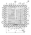
- FIG. 5A is a plan view of a current collecting plate unit included in the redox flow battery shown in FIG. 1 as seen in a plan view from the stacking direction, and is a view for explaining a joint portion between the cell frame and the current collecting plate. ..
- FIG. 5B is a cross-sectional view of the cell frame supply pipe 53 taken along the line b1-b1 of FIG. 5A.
- FIG. 5C is a cross-sectional view of the cell frame discharge path 57 taken along the line b2-b2 of FIG. 5A.
- FIG. 6 is a schematic cross-sectional view of the redox flow battery shown in FIG. 2A taken along the plane AA.
- the redox flow battery 100 of this embodiment includes an ion exchange membrane 10, a current collector 20, an electrode 30, and a cell frame 40.
- the cell frame 40 illustrated in FIG. 1 has a frame shape and is installed so as to surround the outer peripheral surfaces of the current collector plate 20 and the electrode 30.
- the electrode 30 is arranged between the ion exchange membrane 10 and the current collector plate 20.
- the electrode 30 is provided in an electrode chamber formed by the ion exchange membrane 10, the current collector 20 and the cell frame 40.
- the redox flow battery 100 of this embodiment has a cell stack structure in which a plurality of cells CE are stacked.
- one cell CE includes an ion exchange membrane 10, two electrodes 30 functioning as a positive electrode and a negative electrode sandwiching the ion exchange membrane 10, and two electrodes 30 sandwiching the ion exchange membrane 10. And a current collector plate 20 sandwiching it.
- a redox flow battery 100 in which a practical voltage can be obtained is obtained.
- the number of stacked cells CE can be appropriately changed according to the application of the redox flow battery 100, and may be only a single cell.
- the stacking direction of the cell stack structure in which the cells CE are stacked may be simply referred to as the “stacking direction”, and the plane direction perpendicular to the stacking direction of the cell stack structure may be referred to as the “in-plane direction”.
- a current collector unit 200 is provided as the current collector 20 and the cell frame 40.
- the current collector 20 and the cell frame 40 are integrated.
- the ion exchange membrane 10 As the ion exchange membrane 10, it is preferable to use a cation exchange membrane.
- the material for the cation exchange membrane include a perfluorocarbon polymer having a sulfo group, a hydrocarbon-based polymer compound having a sulfo group, a polymer compound doped with an inorganic acid such as phosphoric acid, and a part thereof.
- examples include organic/inorganic hybrid polymers in which is substituted with a proton-conductive functional group, and a proton conductor obtained by impregnating a polymer matrix with a phosphoric acid solution or a sulfuric acid solution.
- the material for the ion exchange membrane 10 is preferably a perfluorocarbon polymer having a sulfo group, more preferably Nafion (registered trademark).
- the collector plate 20 has a role of giving and receiving electrons to and from the electrode 30.
- the current collector plate 20 may have the electrodes 30 arranged on only one surface, or may have the electrodes arranged on both surfaces.
- the collector plate on which the electrodes 30 are arranged on both sides is sometimes called a bipolar plate.
- a conductive material is used as the material of the current collector plate 20.
- the conductive material include a material containing carbon.
- the material containing carbon include a resin containing a carbon material and the like. Specifically, a conductive resin containing graphite and an organic polymer compound, a part of graphite of this conductive resin is carbon black and diamond.
- a conductive resin in which at least one of the like carbons has been substituted can be used.
- the collector plate 20 is preferably a molded body obtained by kneading and molding a carbon material and a resin.
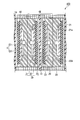
- the current collector plate 20 as viewed in a plan view from the stacking direction has sides extending in the column width direction (left and right direction in FIG. 2A) and sides extending in the column longitudinal direction (up and down direction in FIG. 2A). It has a rectangular shape.
- the current collector plate 20 has a flow path C formed of a groove formed in a concave shape on the surface facing the electrode 30, and the electrolyte solution is supplied to the flow path C through the current collection plate 20. It has a collector plate supply pipe C3.
- the current collector supply pipe C3 has a current collector inlet 21i opened on the outer peripheral surface 201 facing the cell frame 40.
- the current collector plate unit 200 has the current collector plate 20 in which a groove is formed in a concave shape as the channel C on the surface facing the electrode 30. Further, the current collector plate 20 has a current collector plate supply pipe C3 whose outer peripheral surface 201 facing the cell frame 40 is open.
- the flow path C facilitates the supply of the electrolytic solution to the entire surface of the current collector plate 20 facing the electrode 30.
- the flow channel C has a rib-like planar shape and has a first flow channel C1 and a second flow channel C2. That is, the current collector plate 20 has the first flow path C1 and the second flow path C2.
- the first flow path C1 shown in FIG. 2A is a groove having a rectangular cross-section, and only one groove is provided.
- the first flow path C1 extends from the collector plate supply pipe C3 in the extending direction of the collector plate supply pipe C3 (column longitudinal direction in the example shown in FIG. 2A).
- the cross-sectional dimension of the first flow path C1 is preferably set to a value that satisfies a flow rate of 2.0 to 2.5 m/sec, which is an economical guideline for reducing the loss of the hydraulic pipeline.
- the cross-sectional shape of the first flow path C1 can be rectangular as shown in FIG. 2B.
- the second flow channel C2 is a groove having a shallower depth than the first flow channel C1 and having a rectangular cross-section.
- a plurality of second flow paths C2 are provided. Each of the plurality of second flow paths C2 is connected to the first flow path C1 and extends in a direction intersecting with the first flow path C1 (column width direction in the example shown in FIG. 2A). They are arranged symmetrically with respect to C1.
- FIG. 2C is a cross-sectional view of the second flow path C2 taken along the line a2-a2.
- the cross-sectional dimension of the second flow path C2 is preferably set to a value that satisfies the flow rate of 2.0 to 2.5 m/sec, which is an economical guideline for reducing the loss of the hydraulic pipeline.
- the cross-sectional shape of the second flow path C2 can be rectangular as shown in FIG. 2C.
- the symbol P1 is the pitch in the lengthwise direction of the first channel C1 of the second channel C2.
- Reference numeral E1 is a central position between the outflow tips of the second flow passage C2 extending from the first flow passage C1 to both sides.
- Reference numeral E2 is an outflow front end of the second flow path C2.
- Reference symbol E3 is the central position between the outflow tips of the adjacent second flow paths C2.
- a concave portion 20A for accommodating the electrode 30 is concave in a region separated from the edge portion (the outer peripheral surface 201 in plan view). It is provided in.
- the peripheral wall 21 that defines the recess 20A is provided on the surface of the current collector plate 20 facing the electrode 30.
- a channel C is arranged on the bottom surface of the recess 20A.
- An inner wall 22 is formed at a position corresponding to between the grooves of the flow path C. In other words, the flow path C is formed between the inner walls 22.
- the concave portion 20A is provided on the surface of the current collector plate 20 facing the electrode 30, the second electrode 32 having a lower liquid permeability than the first electrode 31 described later and the concave portion 20A.
- the electrolytic solution supplied from the flow path C easily spreads in the in-plane direction. This makes it easier for the electrolytic solution to flow more uniformly over the entire surface of the second electrode 32.
- the depth of the recess 20A is preferably equal to or less than the thickness of the electrode 30.
- the process of manufacturing the redox flow battery 100 of the present embodiment usually includes a process of tightening a plurality of stacked cells CE with bolts. When the electrodes 30 included in each cell CE are crushed by tightening with the bolts, the contact resistance between the current collector plate 20 and the electrodes 30 becomes small. When the depth of the recess 20A is equal to or less than the thickness of the electrode 30, the electrode 30 is easily crushed by the pressing force from the current collector plate 20 by tightening the cell CE with a bolt, and the contact resistance due to the crushing of the electrode 30.
- the effect of reducing In the present embodiment, electrons are generated by the reaction between the surface of the second electrode 32 and the electrolytic solution, and the electrons are transmitted from the second electrode 32 to the first electrode 31 and the current collector plate 20.
- the contact resistance with the electrode 30 is preferably small.
- the effect of reducing the thickness of the electrode 30 by crushing the electrode 30 can be sufficiently obtained. As a result, the moving distance of the ions moving through the ion exchange membrane 10 becomes short, and the cell resistivity decreases, which is preferable.
- current collecting plate discharge paths 23 and 24 for discharging the electrolytic solution are provided along the edges of the surface of the current collecting plate 20 facing the electrode 30.
- the current collector discharge paths 23 and 24 are provided, the discharge of the electrolytic solution from the current collector 20 is promoted, and the electrolytic solution can be supplied to the electrode 30 more uniformly.
- the current collector discharge paths 23 are provided on two parallel sides of the current collector 20 that is rectangular in plan view.
- the current collector discharge passage 24 is provided along the first outer peripheral surface 201a and the second outer peripheral surface 201b.
- the first outer peripheral surface 201a is a surface of the outer peripheral surface 201 where the current collector inlet 21i of the current collector 20 is formed.
- the second outer peripheral surface 201b is a surface of the outer peripheral surface 201 that is arranged in parallel with the first outer peripheral surface 201a in a plan view.
- the collector plate discharge paths 23, 24 are part of the inner wall forming the collector plate discharge paths 23, 24 (in the example shown in FIG. 4, the upper surface and the inside of the collector plate 20). Is preferably the outer surface of the electrode 30. That is, in the current collector unit 200 of the present embodiment, as shown in FIGS. 4 and 6, the side surface of the second electrode 32 described later and the surface of the liquid outflow layer 33 on the current collector 20 side are the current collectors. It also serves as part of the inner walls of the discharge paths 23 and 24.
- the second electrode 32 has a lower liquid permeability than the first electrode 31 and the liquid outflow layer 33, as described later.
- the electrolytic solution supplied from the first electrode 31 to the second electrode 32 is difficult to be discharged from the side surface of the second electrode 32 to the current collector discharge paths 23 and 24, and the electrolytic solution is passed through the second electrode 32 before being discharged. It is likely to be discharged to the current collector plate discharge paths 23, 24 via the outflow layer 33. Therefore, when the side surface of the second electrode 32 and the surface of the liquid outflow layer 33 on the side of the current collector plate 20 also serve as part of the inner walls of the current collector plate discharge paths 23 and 24, the second electrode 32 is used. The charge/discharge reaction can be performed efficiently. Moreover, the flow of the electrolytic solution from the first outer peripheral surface 201a to the collector plate discharge passage 23 can be suppressed.
- FIG. 2D is a cross-sectional view of the current collector plate discharge paths 23 and 24 taken along the line a3-a3.
- the cross-sectional dimensions of the current collector plate discharge passages 23 and 24 are preferably values satisfying a flow rate of 2.0 to 2.5 m/sec, which is an economical index for reducing the loss of the hydraulic pipeline.
- the cross-sectional shape of the current collector discharge paths 23, 24 can be rectangular as shown in FIG. 2D.
- the collector plate discharge paths 23 and 24 have a function of uniformly supplying the electrolyte solution to the electrodes 30 by promoting discharge of the electrolyte solution from the collector plate 20.
- the current collecting plate discharge path 23 has a current collecting plate discharge port 23b on a second outer peripheral surface 201b that is arranged in parallel with the first outer peripheral surface 201a where the current collecting plate inlet 21i is opened. That is, the current collector plate discharge passage 23 has a first outer peripheral surface 201a having the current collector plate inlet 21i formed therein and a second outer peripheral surface 201b having the current collector plate outlet 23b formed therein.
- the starting point 23a of the current collector discharge path 23 is arranged at a position separated from the first outer peripheral surface 201a in a plan view.
- the current collector plate discharge path 24 is arranged so as to connect between the current collector plate discharge ports 23b provided in the two current collector plate discharge paths 23, respectively.
- the distance d in plan view between the starting point 23a of the current collector discharge path 23 and the first outer peripheral surface 201a is more preferably 0.25 mm or more and 4.00 mm or less, and 1.50 mm or more. More preferably, it is 3.00 mm or less. If the distance d is 0.25 mm or more, a seal member 51, which will be described later, has a problem for some reason, and water tightness at the joint between the current collector inlet 21i and the frame opening 53a cannot be sufficiently ensured. Also in the case, the amount of electrolytic solution leaking between the cell frame 40 and the current collector plate 20 can be suppressed more effectively, which is preferable. In addition, it is preferable that the distance d is 4.00 mm or less, because the effect of uniformly providing the electrolytic solution to the electrode 30 due to the provision of the current collector plate discharge passage 23 is obtained.
- the distance d in plan view between the starting point 23a of the current collector discharge path 23 and the first outer peripheral surface 201a is preferably equal to or greater than the thickness of the second electrode 32 described later.
- the second electrode 32 is arranged between the starting point 23a of the current collector discharge path 23 and the first outer peripheral surface 201a in a plan view.
- the second electrode 32 has a lower liquid permeability than the first electrode 31 and the liquid outflow layer 33, as described later. Therefore, when the distance d is equal to or larger than the thickness of the second electrode 32, the electrolytic solution supplied from the current collector plate 20 to the electrode 30 (electrode chamber) and passed through the first electrode 31 causes the current collector plate discharge path.
- the electrolytic solution that has passed through the first electrode 31 is between the starting point 23a of the current collector plate discharge path 23 and the first outer peripheral surface 201a.
- the electrolytic solution easily flows from the first outer peripheral surface 201a to the current collector plate discharge passage 23.
- the distance d in plan view between the starting point 23a of the current collector discharge path 23 and the first outer peripheral surface 201a is more preferably equal to or more than the total thickness of the second electrode 32 and the liquid outflow layer 33 described later. .. In this case, the flow of the electrolytic solution from the first outer peripheral surface 201a to the collector plate discharge passage 23 can be suppressed more effectively.
- the cell frame 40 has a function of preventing the electrolytic solution supplied to the electrode chamber formed by the ion exchange membrane 10, the current collector 20 and the cell frame 40 from leaking out of the electrode chamber.
- plastic such as vinyl chloride resin, polypropylene, polyethylene, fluororesin, epoxy resin or the like may be used, or rubber may be used.
- the cell frame 40 is provided with a cell frame supply pipe 53 and a cell frame discharge path 57.
- the cell frame supply pipe 53 supplies the electrolytic solution to the current collector inlet 21i from the outside such as the electrolytic solution tank.
- the cell frame discharge passage 57 discharges the electrolytic solution supplied to the electrode chamber in which the electrode 30 is formed.
- the cross-sectional shapes of the cell frame supply pipe 53 and the cell frame discharge passage 57 can be appropriately selected, and the dimensions thereof are a flow rate of 2.0 to 2.5 m/sec which is an economical guideline for reducing the loss of the hydraulic pipeline. It is preferable to set the value to satisfy.
- FIG. 5B is a sectional view of the cell frame supply pipe 53 taken along the line b1-b1.
- FIG. 5B shows the size w4 in the column width direction and the height h4 in the stacking direction of the cell frame supply pipe 53.
- the cross-sectional shape of the cell frame supply pipe 53 may be rectangular as shown in FIG. 5B.
- FIG. 5C is a cross-sectional view of the cell frame discharge path 57 taken along the line b2-b2.
- FIG. 5C shows the size w5 in the column width direction and the height h5 in the stacking direction.
- the cross-sectional shape of the cell frame discharge path 57 can be rectangular as shown in FIG. 5C.
- a frame opening 53a for supplying the electrolytic solution from the cell frame supply pipe 53 to the current collector inlet 21i is provided on the surface of the cell frame 40 facing the current collector inlet 21i. That is, a frame opening 53a is formed in the cell frame 40.
- the current collector inlet 21i of the current collector 20 and the frame opening 53a of the cell frame 40 are joined via the seal member 51, so that the current collector 20 and the cell frame 40 are integrated.
- An opening of the cell frame discharge path 57 is provided on the surface of the cell frame 40 facing the current collector discharge port 23b, and is joined to the current collector discharge port 23b.
- a groove having a larger area than the cross-sectional area of the seal member 51 and a thinner thickness than the seal member 51 is formed on the surface of the cell frame 40 facing the current collector inlet 21i. 54 is provided. That is, the current collector plate unit 200 has the cell frame 40 in which the groove 54 is formed on the surface facing the current collector inlet 21i. In this case, since a part of the seal member 51 enters the groove 54, as compared with the case where the groove 54 is not provided, the outer peripheral surface 201a of the current collector plate 20 in which the current collector plate inlet 21i is opened. The gap 52 between the cell frame 40 and the cell frame 40 is narrowed, and the current collector plate unit 200 with less distortion can be obtained.
- the groove 54 is provided, it is possible to prevent the displacement of the seal member 51 when the cell frame 40 and the current collector plate 20 are joined. Furthermore, the widthwise deformation of the seal member 51 caused by the compression of the seal member 51 sandwiched between the cell frame 40 and the current collector plate 20 in the thickness direction is suppressed. As a result, the amount of the electrolytic solution leaking between the cell frame 40 and the current collector plate 20 can be suppressed more effectively.
- An O-ring or the like can be used as the seal member 51.
- an elastic material used for packing such as an O-ring can be used.
- Specific examples of the material of the seal member 51 include rubbers such as ethylene-propylene-diene rubber (EPDM), fluororubber and silicone rubber, and may be appropriately selected according to the application.
- EPDM ethylene-propylene-diene rubber
- fluororubber fluororubber
- silicone rubber such as ethylene-propylene-diene rubber (EPDM), fluororubber and silicone rubber
- the current collector inlet 21 i of the current collector 20 and the frame opening 53 a of the cell frame 40 are arranged to face each other with the seal member 51 interposed therebetween.
- the current collector plate 20 is fitted inside the frame-shaped cell frame 40.
- the seal member 51 is crushed and elastically deformed, water tightness is secured at the joint between the current collector inlet 21i and the frame opening 53a, and the current collector 20 and the cell frame 40 are integrated. Be converted.
- the electrode 30 has liquid permeability.
- the electrode 30 includes a first electrode 31, a second electrode 32, and a liquid outflow layer 33 in order from the current collector 20 side. It is equipped.
- the first electrode 31 is formed so as to fit into the recess 20A of the current collector 20 and cover the flow path C.
- the first electrode 31 exists inside the first surface 21 a of the peripheral wall 21. More specifically, the first electrode 31 is fitted in a region of the recess 20A surrounded by the side surface of the peripheral wall 21 and the first surface 22a of the inner wall 22.
- the first surface 21 a of the peripheral wall 21 is also referred to as a surface on the side facing the electrode 30.
- a flow path C is arranged on the bottom surface of the recess 20A (the first surface 22a of the inner wall 22). Therefore, the electrolytic solution is uniformly supplied from the current collector plate 20 to the first electrode 31. Further, in the present embodiment, the electrolytic solution is likely to be supplied also to the first region D3 immediately above the inner wall 22. Therefore, the difference in the supply state of the electrolytic solution between the first region D3 immediately above the inner wall 22 and the second region D4 between the two inner walls 22 can be reduced.
- the thickness of the first electrode 31 is preferably 0.25 to 0.60 mm, more preferably 0.25 to 0.40 mm.
- the electrolytic solution tends to spread in the in-plane direction, and the flow of the electrolytic solution tends to be more uniform.
- the thickness of the first electrode 31 is 0.60 mm or less, the thickness of the cell CE can be reduced, which is preferable.
- the second electrode 32 is formed over the entire surface of the first electrode 31 on the ion exchange membrane 10 side. Further, as shown in FIGS. 4 and 6, the second electrode 32 is formed so as to cover a part of the first surface 21a of the peripheral wall 21, and is provided on the side of the current collector 20 other than the current collector inlet 21i side. It is provided apart from the edge portion (outer peripheral surface 201 except the first outer peripheral surface 201a of the current collector plate 20 in plan view). As a result, at the edge portion other than the side of the current collector inlet 21i, as shown in FIGS. 4 and 6, the current collector discharge path 23 including the space sandwiched between the second electrode 32 and the cell frame 40, 24 are formed.
- the second electrode 32 is The first electrode 31 is provided continuously from the surface on the ion exchange membrane 10 side so as to cover the first surface 21 a of the peripheral wall 21. Further, as shown in FIG. 6, the second electrode 32 is provided at one edge portion 21b (edge portion on the side of the current collector plate inlet 21i) in the column longitudinal direction of the first surface 21a of the peripheral wall 21. It is provided continuously from the surface of the first electrode 31 on the ion exchange membrane 10 side so as to cover the first surface 21 a of the peripheral wall 21.
- the thickness of the second electrode 32 is preferably 0.01 to 0.80 mm, more preferably 0.02 to 0.50 mm.
- the thickness of the second electrode 32 is 0.01 mm or more, the conductivity of the second electrode 32 becomes good, which is preferable.
- the thickness of the second electrode 32 is 0.80 mm or less, the liquid resistance of the electrolytic solution in the second electrode 32 does not become too large, and good liquid permeability can be obtained.
- the liquid outflow layer 33 is formed on the surface of the second electrode 32 on the ion exchange membrane 10 side, and is arranged in contact with the ion exchange membrane 10.
- the liquid outflow layer 33 is provided so as to spread over the entire area surrounded by the cell frame 40.
- the thickness of the liquid outflow layer 33 is preferably 0.10 to 0.35 mm, more preferably 0.10 to 0.20 mm. When the thickness of the liquid outflow layer 33 is 0.10 mm or more, the effect of discharging the electrolytic solution becomes remarkable, and the pressure required to pass the electrolytic solution through the electrode 30 is small, which is preferable.
- the thickness of the liquid outflow layer 33 is 0.35 mm or less, the distance between the second electrode 32 and the ion exchange membrane 10 does not become too wide (the mobility of ions does not become too large), and the cell resistance is low. It is preferable because the increase in the rate is suppressed.
- a conductive sheet containing carbon fibers can be used as a material for the electrodes 30 (first electrode 31, second electrode 32, liquid outflow layer 33).
- the carbon fiber referred to here is fibrous carbon, and specific examples thereof include carbon fiber and carbon nanotube.
- the electrically conductive sheet containing carbon fibers for example, carbon felt, carbon paper, carbon nanotube sheet or the like can be used.
- the electrode 30 made of a conductive sheet containing carbon fiber By using the electrode 30 made of a conductive sheet containing carbon fiber, a highly reactive redox flow battery 100 in which the contact area between the electrolytic solution and the electrode 30 is sufficiently secured can be obtained.
- the electrode 30 includes carbon nanotubes having a fiber diameter of 1 ⁇ m or less, the fiber diameter of the carbon nanotubes is sufficiently small, so that the contact area between the electrolytic solution and the electrode 30 can be increased more effectively, which is preferable.
- a conductive sheet containing carbon fibers having a fiber diameter of 1 ⁇ m or more has high strength and is not easily broken. Therefore, when the electrode 30 contains carbon fibers having a fiber diameter of 1 ⁇ m or more, the redox flow battery 100 has high strength, which is preferable.
- the liquid outflow layer 33 may be porous (porous) having a large number of holes through which the electrolytic solution passes, and may have conductivity, or may not have conductivity. Good. When the liquid outflow layer 33 has conductivity, the cell CE having even lower resistance is obtained, which is preferable.
- the first electrode 31 preferably has higher liquid permeability than the second electrode 32.
- the liquid permeability of the first electrode 31 is higher than the liquid permeability of the second electrode 32, the flow of the electrolytic solution flowing into the first electrode 31 is blocked by the second electrode 32 and easily spreads in the in-plane direction. This makes it easier for the electrolytic solution to flow more uniformly over the entire surface of the second electrode 32.
- the transmittance of the first electrode 31 is preferably 100 times or more, more preferably 300 times or more, and 1000 times or more, as compared with the transmittance of the second electrode 32. Is more preferable.
- a carbon felt or a carbon paper made of carbon fiber or the like having a fiber diameter of 1 ⁇ m or more is used as the first electrode 31, and a carbon nanotube having a fiber diameter of 1 ⁇ m or less is used as the second electrode 32.
- the case where a carbon nanotube sheet or the like constituted by The transmittance of the first electrode 31 means the transmittance in the in-plane direction.
- the transmittance of the second electrode 32 means the transmittance in the stacking direction (the normal direction to the in-plane direction).
- the liquid outflow layer 33 has a function of guiding the electrolytic solution flowing out from the second electrode 32 to the discharge path. Therefore, the liquid outflow layer 33 preferably has higher liquid permeability than the second electrode 32.
- the liquid permeability of the liquid outflow layer 33 in the in-plane direction is higher than the liquid permeability of the second electrode 32 in the stacking direction, the electrolytic solution is quickly discharged to the current collector plate discharge paths 23, 24 through the liquid outflow layer 33.
- the difference in the flow of the electrolytic solution in the vicinity of the collector plate discharge paths 23, 24 of the second electrode 32 is reduced.
- the charge/discharge reaction can be efficiently performed using the entire surface of the second electrode 32, and the cell CE having low resistance is obtained, which is preferable.
- the transmittance of the liquid outflow layer 33 is preferably 50 times or more, more preferably 100 times or more, and 300 times or more as compared with the transmittance of the second electrode 32. Is more preferable and 1000 times or more is particularly preferable.
- a carbon felt or carbon paper made of carbon fiber or the like having a fiber diameter of 1 ⁇ m or more is used, and the second electrode 32 is used.
- a carbon nanotube sheet composed of carbon nanotubes having a fiber diameter of 1 ⁇ m or less is used.
- the transmittance of the liquid outflow layer 33 means the transmittance in the in-plane direction.
- the electrode 30 has a first electrode 31, a second electrode 32, and a liquid outflow layer 33 stacked in this order from the current collector 20 side.
- the liquid permeability of the first electrode 31 and the liquid outflow layer 33 is higher than that of the second electrode 32. Therefore, the entire surface of the second electrode 32 can be used to efficiently perform the charge/discharge reaction.
- the liquid permeability of the electrode 30 can be evaluated by the transmittance of the Darcy's law (hereinafter, simply referred to as transmittance).
- the Darcy's law is commonly used to describe the permeability of porous media.
- the Darcy's law can be applied to members other than the porous material for convenience. At that time, for the non-uniform and anisotropic member, the transmittance in the direction having the lowest transmittance is adopted.
- the transmittance k(m 2 ) is the cross-sectional area S(m 2 ) of a member through which a liquid having a viscosity ⁇ (Pa ⁇ sec) is passed, the length L(m) of the member, and the flow rate Q(m 3 / sec) is calculated from the differential pressure ⁇ P (Pa) between the liquid inflow side and the liquid outflow side of the member when the liquid has passed through, from the relationship of the liquid permeation flux (m/sec) represented by the following equation.
- Electrolytic solution As the electrolytic solution, a known electrolytic solution that can be used as an electrolytic solution of a redox flow battery can be used. For example, a vanadium sulfate aqueous solution can be used as the electrolytic solution.
- the electrolytic solution supplied into the electrode 30 reacts with the electrode 30. Ions generated during the reaction flow between the electrodes 30 via the ion exchange membrane 10 to charge and discharge.
- the electrolytic solution after the reaction is discharged to the cell frame discharge path 57 of the cell frame 40 from the current collector discharge port 23b via the collector plate discharge paths 23 and 24 of the collector plate 20.
- the electrolytic solution supplied from the current collector inlet 21i to the current collector supply pipe C3 flows along the first flow path C1 of the flow path C (flow f11). , Branched from the first flow path C1 and flows along the second flow path C2 (flow f12). That is, the electrolytic solution is spread and flowed in the in-plane direction of the recess 20A.
- the electrolytic solution that has spread over the entire surface of the recess 20A through the flow path C passes through the electrode 30 while reacting, and is discharged through the current collector plate discharge paths 23 and 24 (flow f13).
- the electrode 30 is used over the entire in-plane direction. As a result, the resistance of the cell CE of the redox flow battery 100 is reduced, and the charge/discharge characteristics are improved.
- the current collector inlet 21i and the frame opening 53a are joined via the seal member 51. Therefore, it is possible to prevent the electrolytic solution from leaking into the gap 52 between the cell frame 40 and the first outer peripheral surface 201a of the current collector plate 20, which is caused by fitting the current collector plate 20 into the frame-shaped cell frame 40. it can. As a result, the gap 52 between the current collector plate 20 and the cell frame 40 serves as a flow path, and the amount of the electrolytic solution discharged without the reaction at the electrodes is suppressed.
- the redox flow battery 100 of the present embodiment which is provided with the current collector unit 200 of the present embodiment as the current collector 20 and the cell frame 40, has the amount of electrolyte leaked from between the cell frame 40 and the current collector 20. Is suppressed. Therefore, in the redox flow battery 100 of the present embodiment, the amount (leak amount) of the electrolyte solution supplied from the cell frame 40 that is not supplied to the electrodes 30 and discharged is small, and the liquid capacity density (kWh/m). 3 ) High.
- the shape of the current collector plate 20 is not limited to the configurations shown in FIGS. 1 to 6.
- the planar shape and cross-sectional shape of the flow path C of the current collector plate 20 are not limited to the shapes shown in FIGS. 2A to 6, but the size of the current collector plate 20 and the current collector plate unit may be different. It can be appropriately determined according to the application of the redox flow battery provided, and is not particularly limited.
- the electrode 30 is not limited to the one in which the first electrode 31, the second electrode 32, and the liquid outflow layer 33 are stacked in this order from the side of the current collector plate 20 shown in FIG. 4.
- the electrode may be composed of one layer, two layers, or four or more layers.
- the differential equation (continuous equation, momentum conservation law) used in the discrete computational fluid dynamics analysis of this system is referred to as "treated as a laminar flow” as a calculation method that does not perform time averaging of the flow velocity.
- the differential equation to be handled will include the equation of the turbulence effect. This case is called “treated as turbulent flow”.
- the distance d and the width of the gap shown in Table 1 are as shown below.
- Distance d a distance in plan view between the starting point 23a of the current collector discharge path 23 shown in FIG. 2A and the outer peripheral surface (first outer peripheral surface 201a) of the current collector 20 in which the current collector inlet 21i is opened.
- Is. Width of gap A gap 52 between the current collector plate 20 and the cell frame 40 shown in FIG. 2A, and the dimension calculated from the fitting tolerance between these was set to 0.01 mm.
- Condition 1 to 6 shown in Table 1 are cases where the seal member 51 is not installed.
- Condition 7 was a case where the seal member 51 was installed, and there was no electrolytic solution leaking between the cell frame 40 and the current collector plate 20 (no leak).
- W1 The length of the second flow path C2.
- W2 The distance between the first flow path C1 and the current collector plate discharge path 23.
- W3 The length of the first surface 21a of the peripheral wall 21 in the column width direction.
- W4 Column width.
- L1 The length of the first flow path C1.
- L2 Length in the column longitudinal direction.
- the cross-sectional shapes of the cell frame supply pipe 53 and the cell frame discharge passage 57 are as shown below, and correspond to the reference numerals in FIGS. 5B and 5C.
- the electrolytic solution was a vanadium sulfate aqueous solution (V concentration 1.8 mol/L, sulfuric acid concentration 4.5 mol/L).
- the flow rate (Q) (hereinafter referred to as “total flow rate”) flowing into the column width (W4) ⁇ length in the column longitudinal direction (L2) was set to 25 mL/min, and the flow velocity in the normal direction of the electrode central cross section was kept constant. The flow rate was adjusted to keep it.
- the outflow condition of the electrolytic solution was free outflow.
- the thickness of the first electrode was 0.37 mm, and the transmittance in the in-plane direction was 7.1 ⁇ 10 ⁇ 11 [m 2 ].
- the thickness of the second electrode was 0.40 mm, and the transmittance in the stacking direction (in-plane normal direction) was 2.7 ⁇ 10 ⁇ 13 [m 2 ].
- the thickness of the liquid outflow layer was 0.11 mm, and the transmittance in the in-plane direction was 4.1 ⁇ 10 ⁇ 11 [m 2 ].
- the transmittance of each layer was calculated using the Darcy's law.
- the total sum of the flow rates of the obtained regions was divided by the cross-sectional area (width 1.0 mm, height 0.5 mm) of the current collector plate supply pipe C3 to obtain the flow rate of the current collector plate supply pipe C3. This value was defined as the flow rate (Q2) introduced into the cell. Since the total flow rate (Q) was 25 mL/min, the leak amount was calculated from the difference (Q-Q2) between them.
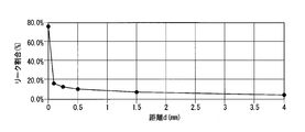
- FIG. 7 is a graph showing the relationship between the distance d and the leak rate.
- the vertical axis represents the leak rate and the horizontal axis represents the distance d.
- the distance d is preferably 0.10 mm or more and 4.00 mm or less, and is 0.25 mm or more and 2.00 mm or less. Is more preferable. Further, it is desirable that the distance d is 0.50 mm or more and 1.50 mm or less from the viewpoint of uniformity of the supply of the electrolytic solution to the second electrode.
- FIG. 8 is a graph showing the relationship between the distance d and the liquid volume density (relative value).
- the vertical axis represents the liquid volume density (relative value)
- the horizontal axis represents the distance d.
- the distance d is preferably 0.10 mm or more and 4.00 mm or less, and 0.25 mm or more and 2 More preferably, it is 0.000 mm or less. Further, it is desirable that the distance d is 0.50 mm or more and 1.50 mm or less from the viewpoint of uniformity of the supply of the electrolytic solution to the second electrode.
- the charge/discharge curve always has the charge curve at the top and the discharge curve at the bottom. This is due to the internal resistance of the battery. That is, at the time of discharging, the voltage drop (overvoltage) corresponding to the internal resistance of the battery becomes the discharging voltage with respect to the open end voltage (voltage when no current is flowing). On the other hand, in charging, the voltage increase (overvoltage) corresponding to the internal resistance of the battery becomes the charging voltage with respect to the open circuit voltage.
- the voltage (V 1 ) at 1/2 of the charge capacity obtained from the charge curve is the charging voltage.
- the voltage (V 2 ) at 1/2 of the discharge capacity obtained from the discharge curve is used as the discharge voltage in the method of calculating the cell resistivity [ ⁇ cm 2 ] by the midpoint method.
- the circulating electrolytic solution can be effectively supplied to the electrodes. Therefore, in the redox flow battery of the present invention, the electrodes can be efficiently utilized to the maximum during charging and discharging. Therefore, the redox flow battery of the present invention is suitable as a redox flow battery of a large capacity storage battery.
- 10 ion exchange membrane 20 current collector, 20A recess, 21 peripheral wall, 21a first surface, 21i current collector inlet, 22 inner wall, 22a first surface of inner wall, 23, 24 current collector discharge path, 23a starting point, 23b current collector discharge port, 30 electrode, 31 first electrode, 32 second electrode, 33 liquid outflow layer, 40 cell frame, 51 seal member, 52 gap, 53 cell frame supply pipe, 53a frame opening, 54 groove, 57 cell frame discharge passage, 100 redox flow battery, 200 current collector plate unit, 201 outer peripheral surface, 201a first outer peripheral surface, 201b second outer peripheral surface, CE cell, C flow path, C1 first flow path, C2 second flow path, C3 collector plate supply pipe
Landscapes
- Chemical & Material Sciences (AREA)
- Chemical Kinetics & Catalysis (AREA)
- Electrochemistry (AREA)
- General Chemical & Material Sciences (AREA)
- Life Sciences & Earth Sciences (AREA)
- Engineering & Computer Science (AREA)
- Manufacturing & Machinery (AREA)
- Sustainable Development (AREA)
- Sustainable Energy (AREA)
- Fuel Cell (AREA)
Abstract
この集電板ユニットは、イオン交換膜と集電板との間に配置された電極と、集電板および電極の外周面を囲む枠状のセルフレームとを有するレドックスフロー電池に用いられる集電板ユニットであり、集電板ユニット(200)は、集電板(20)とセルフレーム(40)とが一体化されてなり、集電板は、電極との対向面に凹状に形成された溝からなる流路と、集電板を貫通して流路に電解液を供給する集電板供給管とを有し、集電板供給管は、セルフレームと対向する外周面に開口された集電板流入口を有し、セルフレームの集電板流入口との対向面には、集電板流入口に電解液を供給するフレーム開口部が設けられ、集電板流入口(21i)とフレーム開口部(53a)とが、シール部材(51)を介して接合されている。
Description
本発明は、集電板ユニットおよびレドックスフロー電池に関する。
本願は、2018年12月27日に日本に出願された特願2018-244992に基づき優先権を主張し、その内容をここに援用する。
本願は、2018年12月27日に日本に出願された特願2018-244992に基づき優先権を主張し、その内容をここに援用する。
大容量蓄電池として、レドックスフロー電池が知られている。レドックスフロー電池としては、イオン交換膜と、集電板と、イオン交換膜と集電板との間に配置された電極と、集電板および電極の外周を囲むセルフレームとを有するものがある。レドックスフロー電池では、電極で酸化反応と還元反応とを同時に進めることにより充放電が行われる。
レドックスフロー電池としては、電解液が集電板側の面からイオン交換膜側の面に流れる主電極層を有する電極を備え、主電極層は、面方向に並置された複数の主電極片からなるものが提案されている(例えば、特許文献1参照。)。
また、電解液が導入される上流側端部を起点とし、電解液が排出される下流側端部に連続しない電解液の流通溝を有するレドックスフロー電池用電極を用いたレドックスフロー電池が知られている(例えば、特許文献2参照。)。
また、電解液が導入される上流側端部を起点とし、電解液が排出される下流側端部に連続しない電解液の流通溝を有するレドックスフロー電池用電極を用いたレドックスフロー電池が知られている(例えば、特許文献2参照。)。
しかしながら、従来のレドックスフロー電池では、セルフレームから供給される電解液のうち、電極に供給されずに排出される電解液の量が多いという不都合があった。電極に供給されずに排出される電解液は、充放電に寄与しない。このため、従来のレドックスフロー電池では、電極に供給されずに排出される電解液量(リーク量)を低減させて、液容量密度(kWh/m3)を向上させることが要求されていた。
本発明は、上記事情を鑑みてなされたものであり、レドックスフロー電池の集電板およびセルフレームとして用いることにより、セルフレームから供給される電解液のうち、電極に供給されずに排出される量(リーク量)を抑制でき、液容量密度が高いレドックスフロー電池が得られる集電板ユニットを提供することを課題とする。
また、本発明は、本発明の集電板ユニットが備えられ、リーク量が少なく、液容量密度が高いレドックスフロー電池を提供することを課題とする。
また、本発明は、本発明の集電板ユニットが備えられ、リーク量が少なく、液容量密度が高いレドックスフロー電池を提供することを課題とする。
本発明者は、上記課題を解決するために、セルフレームから供給される電解液のうち、電極に供給されずに排出される電解液の流れに着目して、鋭意検討を重ねた。
その結果、従来、電極に供給されずに排出される電解液として検討されていなかった、セルフレームと集電板との間から漏れる電解液量を低減することが効果的であることを見出した。
その結果、従来、電極に供給されずに排出される電解液として検討されていなかった、セルフレームと集電板との間から漏れる電解液量を低減することが効果的であることを見出した。
より詳細には、レドックスフロー電池を製造する際には、通常、集電板をセルフレームに嵌め込む方法を用いている。このため、セルフレームと集電板との間には、これらの分解および組み立てを行うために必要な嵌めあい公差に起因する隙間が存在する。本発明者は、この隙間が、電極に供給されずに排出される電解液の発生源になっているとともに、電極で反応を行うことなしに電解液が排出される流路となっていることを見出した。
そこで、本発明者は、セルフレームと集電板との間から漏れる電解液量を抑制すべく、検討を重ねた。そして、セルフレームから集電板に電解液を供給するセルフレーム供給管のフレーム開口部と、集電板に電解液を流入させる集電板流入口とを、シール部材を介して接合することで、セルフレームと集電板との間から漏れる電解液を低減できることを確認し、本発明を完成するに至った。
すなわち、本発明は以下の事項に関する。
すなわち、本発明は以下の事項に関する。
(1)本発明の第一の態様にかかる集電板ユニットは、イオン交換膜と集電板との間に配置された電極と、前記集電板および前記電極の外周面を囲む枠状のセルフレームとを有するレドックスフロー電池に用いられる集電板ユニットであり、
前記集電板ユニットは、前記集電板と前記セルフレームとが一体化されてなり、
前記集電板は、前記電極との対向面に凹状に形成された溝からなる流路と、前記集電板を貫通して前記流路に電解液を供給する集電板供給管とを有し、前記集電板供給管は、前記セルフレームと対向する前記外周面に開口された集電板流入口を有し、
前記セルフレームの前記集電板流入口との対向面には、前記集電板流入口に前記電解液を供給するフレーム開口部が設けられ、
前記集電板流入口と前記フレーム開口部とが、シール部材を介して接合されている。
前記集電板ユニットは、前記集電板と前記セルフレームとが一体化されてなり、
前記集電板は、前記電極との対向面に凹状に形成された溝からなる流路と、前記集電板を貫通して前記流路に電解液を供給する集電板供給管とを有し、前記集電板供給管は、前記セルフレームと対向する前記外周面に開口された集電板流入口を有し、
前記セルフレームの前記集電板流入口との対向面には、前記集電板流入口に前記電解液を供給するフレーム開口部が設けられ、
前記集電板流入口と前記フレーム開口部とが、シール部材を介して接合されている。
(2)上記態様にかかる集電板ユニットは、前記セルフレームの前記集電板流入口との対向面に、前記シール部材の断面積よりも広い面積を有し、前記シール部材よりも厚みの薄い溝が設けられていてもよい。
(3)上記態様にかかる集電板ユニットは、前記集電板は、平面視矩形であり、
前記集電板の前記電極との対向面の縁部に沿って、前記電解液を排出する集電板排出路が設けられ、
前記集電板排出路は、前記集電板流入口が開口されている第1外周面と平面視で並行に配置された第2外周面に集電板排出口を有し、前記集電板排出路の起点は、前記第1外周面と平面視で離間する位置に配置されていてもよい。
前記集電板の前記電極との対向面の縁部に沿って、前記電解液を排出する集電板排出路が設けられ、
前記集電板排出路は、前記集電板流入口が開口されている第1外周面と平面視で並行に配置された第2外周面に集電板排出口を有し、前記集電板排出路の起点は、前記第1外周面と平面視で離間する位置に配置されていてもよい。
(4)上記態様にかかる集電板ユニットは、前記電極が、前記集電板側から順に、第1電極と、第2電極と、液流出層とが積層されたものであり、前記第1電極および前記液流出層の通液性が前記第2電極よりも高くてもよい。
(5)上記態様にかかる集電板ユニットは、前記第2電極の側面および前記液流出層の集電板側の面が、前記集電板排出路の内壁の一部を兼ねていてもよい。
(6)上記態様にかかる集電板ユニットは、前記集電板排出路の起点と、前記第1外周面との平面視での距離が、前記第2電極の厚み以上であってもよい。
(6)上記態様にかかる集電板ユニットは、前記集電板排出路の起点と、前記第1外周面との平面視での距離が、前記第2電極の厚み以上であってもよい。
(7)上記態様にかかる集電板ユニットは、前記集電板の前記電極との対向面であって縁部から離間した領域に、前記電極が収納される凹部が設けられ、前記凹部の底面に前記流路が配置されていてもよい。
(8)上記態様にかかる集電板ユニットは、前記凹部の深さが、前記電極の厚さ以下であってもよい。
(8)上記態様にかかる集電板ユニットは、前記凹部の深さが、前記電極の厚さ以下であってもよい。
(9)上記態様にかかる集電板ユニットは、前記集電板排出路が、前記集電板の平行な2辺にそれぞれ設けられていてもよい。
(10)上記態様にかかる集電板ユニットは、前記集電板排出路の起点と、前記第1外周面との平面視での距離が、0.25mm以上4mm以下であってもよい。
(10)上記態様にかかる集電板ユニットは、前記集電板排出路の起点と、前記第1外周面との平面視での距離が、0.25mm以上4mm以下であってもよい。
(11)本発明の第二の態様にかかるレドックスフロー電池は、イオン交換膜と集電板との間に配置された電極と、前記集電板の外周面を囲む枠状のセルフレームとを有するレドックスフロー電池であり、
前記集電板および前記セルフレームとして、(1)~(10)のいずれかに記載の集電板ユニットが備えられている。
前記集電板および前記セルフレームとして、(1)~(10)のいずれかに記載の集電板ユニットが備えられている。
本発明の集電板ユニットでは、集電板流入口とフレーム開口部とが、シール部材を介して接合されている。このため、本発明の集電板ユニットを、集電板およびセルフレームとして備えたレドックスフロー電池とすることで、セルフレームと集電板との間から漏れる電解液量を抑制できる。その結果、セルフレームから供給される電解液のうち、電極に供給されずに排出される量(リーク量)が少なく、液容量密度(kWh/m3)の高いレドックスフロー電池を提供できる。
以下、本発明の集電板ユニットおよびレドックスフロー電池の好ましい実施形態について、図面を参照しながら詳細に説明する。なお、以下の説明で用いる図面は、本発明の特徴をわかりやすくするために便宜上特徴となる部分を拡大して示している場合がある、このため、各構成要素の寸法比率などは実際とは異なっていることがある。また、以下の説明において例示される材質、寸法、数値や量や比率や特性等は一例である。したがって、本発明は、以下に示す実施形態のみに限定されず、本発明の要件を変更しない範囲で適宜変更して実施できる。例えば、本発明の主旨を逸脱しない範囲で材質、寸法、数値や量や比率や特性等を省略、追加および変更などをしてもよい。
図1~図6は、本発明のレドックスフロー電池の一例として、本実施形態のレドックスフロー電池を説明するための図である。図1~図6について、同じ部材には同じ符号を付しており、説明を省略している場合がある。
図1は、本実施形態のレドックスフロー電池を示した断面模式図である。
図2Aは、図1に示すレドックスフロー電池に備えられている集電板ユニットを積層方向から平面視した平面図である。図2Bは、図2Aのa1-a1矢視で切断した第1流路C1の断面図である。図2Bは、第1流路C1のカラム幅方向の大きさおよび積層方向の高さを示す。図2Cは、図2Aのa2-a2矢視で切断した第2流路C2の断面図である。図2Cは、第2流路C2のカラム長手方向の大きさおよび積層方向の高さを示す。図2Dは、図2Aのa3-a3矢視で切断した集電板排出路23の断面図である。図2Dは、集電板排出路23のカラム幅方向の大きさおよび積層方向の高さを示す。
図3は、図2Aで示されるレドックスフロー電池の集電板をA-A面で切断した断面模式図である。
図4は、図1に示すレドックスフロー電池における1つのセルをカラム幅方向から見た断面模式図である。すなわち、レドックスフロー電池における1つのセルを、第1流路C1の延びる方向と平行に見た断面模式図である。
図5Aは、図1に示すレドックスフロー電池に備えられている集電板ユニットを積層方向から平面視した平面図であり、セルフレームと集電板との接合部を説明するための図である。図5Bは、図5Aのb1-b1矢視で切断したセルフレーム供給管53の断面図である。図5Cは、図5Aのb2-b2矢視で切断したセルフレーム排出路57の断面図である。
図6は、図2Aで示されるレドックスフロー電池をA-A面で切断した断面模式図である。
図1に示すように、本実施形態のレドックスフロー電池100は、イオン交換膜10と、集電板20と、電極30と、セルフレーム40とを有する。図1に示すセルフレーム40は、枠状であり、集電板20および電極30の外周面を囲むように設置されている。
図1および図4に示すように、電極30は、イオン交換膜10と集電板20との間に配置されている。電極30は、図1に示すように、イオン交換膜10と集電板20とセルフレーム40によって形成された電極室内に設けられている。
図1および図4に示すように、電極30は、イオン交換膜10と集電板20との間に配置されている。電極30は、図1に示すように、イオン交換膜10と集電板20とセルフレーム40によって形成された電極室内に設けられている。
図1に示すように、本実施形態のレドックスフロー電池100は、複数のセルCEが積層されたセルスタック構造を有する。図1および図4に示すように、1つのセルCEは、イオン交換膜10と、イオン交換膜10を挟む正極及び負極として機能する2つの電極30と、イオン交換膜10を挟む2つの電極30を挟む集電板20とを有する。図1および図4に示すセルCEを、複数直列接続することにより、実用的な電圧が得られるレドックスフロー電池100となる。セルCEの積層数は、レドックスフロー電池100の用途などに応じて適宜変更することができ、単セルのみであってもよい。
以下、セルCEが積層されるセルスタック構造の積層方向を単に「積層方向」、セルスタック構造の積層方向に垂直な面方向を「面内方向」と言うことがある。
本実施形態のレドックスフロー電池100では、図2Aに示すように、集電板20およびセルフレーム40として、集電板ユニット200が備えられている。集電板ユニット200は、集電板20とセルフレーム40とが一体化されている。
「イオン交換膜」
イオン交換膜10としては、陽イオン交換膜を用いることが好ましい。陽イオン交換膜の材料としては、具体的には、スルホ基を有するパーフルオロカーボン重合体、スルホ基を有する炭化水素系高分子化合物、リン酸などの無機酸をドープさせた高分子化合物、一部がプロトン伝導性の官能基で置換された有機/無機ハイブリッドポリマー、高分子マトリックスにリン酸溶液や硫酸溶液を含浸させたプロトン伝導体等が挙げられる。イオン交換膜10の材料としては、上記の中でも特に、スルホ基を有するパーフルオロカーボン重合体が好ましく、ナフィオン(登録商標)がより好ましい。
イオン交換膜10としては、陽イオン交換膜を用いることが好ましい。陽イオン交換膜の材料としては、具体的には、スルホ基を有するパーフルオロカーボン重合体、スルホ基を有する炭化水素系高分子化合物、リン酸などの無機酸をドープさせた高分子化合物、一部がプロトン伝導性の官能基で置換された有機/無機ハイブリッドポリマー、高分子マトリックスにリン酸溶液や硫酸溶液を含浸させたプロトン伝導体等が挙げられる。イオン交換膜10の材料としては、上記の中でも特に、スルホ基を有するパーフルオロカーボン重合体が好ましく、ナフィオン(登録商標)がより好ましい。
「集電板」
集電板20は、電極30に電子を授受する役割を持つ。集電板20は、一方の面にのみ電極30が配置されるものであってもよいし、両面に電極が配置されるものであってもよい。両面に電極30が配置される集電板は、双極板と言われることもある。
集電板20は、電極30に電子を授受する役割を持つ。集電板20は、一方の面にのみ電極30が配置されるものであってもよいし、両面に電極が配置されるものであってもよい。両面に電極30が配置される集電板は、双極板と言われることもある。
集電板20の材料としては、導電性材料が用いられる。導電性材料としては、例えば、炭素を含有する材料などが挙げられる。炭素を含有する材料としては、炭素材料を含む樹脂などが挙げられ、具体的には、黒鉛と有機高分子化合物とを有する導電性樹脂、この導電性樹脂の黒鉛の一部をカーボンブラックとダイヤモンドライクカーボンの少なくとも1つに置換した導電性樹脂などが挙げられる。
集電板20は、炭素材料と樹脂とを混練成形した成形体であることが好ましい。
集電板20は、炭素材料と樹脂とを混練成形した成形体であることが好ましい。
図2Aに示すように、積層方向から平面視した集電板20は、カラム幅方向(図2Aにおける左右方向)に延びる辺と、カラム長手方向(図2Aにおける上下方向)に延びる辺とを有する矩形形状である。
集電板20は、図2Aに示すように、電極30との対向面に凹状に形成された溝からなる流路Cと、集電板20を貫通して流路Cに電解液を供給する集電板供給管C3とを有する。集電板供給管C3は、セルフレーム40と対向する外周面201に開口された集電板流入口21iを有する。すなわち集電板ユニット200は、電極30と対向面に、流路Cとして凹状に溝が形成された集電板20を有する。また、集電板20は、セルフレーム40と対向する外周面201が開口している集電板供給管C3を有する。
集電板20は、図2Aに示すように、電極30との対向面に凹状に形成された溝からなる流路Cと、集電板20を貫通して流路Cに電解液を供給する集電板供給管C3とを有する。集電板供給管C3は、セルフレーム40と対向する外周面201に開口された集電板流入口21iを有する。すなわち集電板ユニット200は、電極30と対向面に、流路Cとして凹状に溝が形成された集電板20を有する。また、集電板20は、セルフレーム40と対向する外周面201が開口している集電板供給管C3を有する。
流路Cは、集電板20の電極30との対向面全面に電解液が供給されやすくする。流路Cは、図2Aに示すように、あばら骨状の平面形状であり、第1流路C1と第2流路C2とを有する。すなわち、集電板20は第1流路C1と第2流路C2とが形成されている。
図2Aに示す第1流路C1は、断面視矩形の溝であり、1本のみ設けられている。
第1流路C1は、集電板供給管C3から集電板供給管C3の延在方向(図2Aに示す例ではカラム長手方向)に延在している。
図2Bは、a1-a1矢視で切断した第1流路C1の断面図である。第1流路C1の断面寸法は、水力学の管路の損失を小さくする経済的な目安とされる流量2.0~2.5m/secを満たす値とすることが好ましい。第1流路C1の断面形状は、図2Bに示すように矩形とすることができる。
図2Aに示す第1流路C1は、断面視矩形の溝であり、1本のみ設けられている。
第1流路C1は、集電板供給管C3から集電板供給管C3の延在方向(図2Aに示す例ではカラム長手方向)に延在している。
図2Bは、a1-a1矢視で切断した第1流路C1の断面図である。第1流路C1の断面寸法は、水力学の管路の損失を小さくする経済的な目安とされる流量2.0~2.5m/secを満たす値とすることが好ましい。第1流路C1の断面形状は、図2Bに示すように矩形とすることができる。
図2A、図3、図4に示すように、第2流路C2は、第1流路C1よりも深さの浅い断面視矩形の溝である。第2流路C2は、複数本設けられている。複数の第2流路C2のそれぞれは、第1流路C1に繋がっており、第1流路C1から交差する方向(図2Aに示す例ではカラム幅方向)に延在し、第1流路C1に対して対称に配置されている。
図2Cは、a2-a2矢視で切断した第2流路C2の断面図である。第2流路C2の断面寸法は、水力学の管路の損失を小さくする経済的な目安とされる流量2.0~2.5m/secを満たす値とすることが好ましい。第2流路C2の断面形状は、図2Cに示すように矩形とすることができる。
図2Cは、a2-a2矢視で切断した第2流路C2の断面図である。第2流路C2の断面寸法は、水力学の管路の損失を小さくする経済的な目安とされる流量2.0~2.5m/secを満たす値とすることが好ましい。第2流路C2の断面形状は、図2Cに示すように矩形とすることができる。
図2Aにおいて、符号P1は、第2流路C2の第1流路C1の長さ方向ピッチである。符号E1は、第1流路C1から両側に伸びる第2流路C2の流出先端間の中央位置である。符号E2は、第2流路C2の流出先端である。符号E3は、隣り合う第2流路C2の流出先端間の中央位置である。
図2Aおよび図3に示すように、集電板20の電極30との対向面には、縁部(平面視で外周面201)から離間した領域に、電極30が収納される凹部20Aが凹状に設けられている。言い換えると、集電板20の電極30との対向面側には、凹部20Aを画成する周縁壁21が設けられている。
凹部20Aの底面には、流路Cが配置されている。流路Cの溝の間に当る位置には、内部壁22が形成されている。言い換えると、内部壁22と内部壁22の間に流路Cが形成されている。
凹部20Aの底面には、流路Cが配置されている。流路Cの溝の間に当る位置には、内部壁22が形成されている。言い換えると、内部壁22と内部壁22の間に流路Cが形成されている。
本実施形態では、集電板20の電極30との対向面に凹部20Aが設けられているので、後述する第1電極31と比較して通液性が低い第2電極32と、凹部20Aとに囲まれた領域に設けられた第1電極31内で、流路Cから供給された電解液が面内方向に広がりやすくなる。このことにより、第2電極32全面に電解液をより均一に流入させやすくなる。
また、本実施形態では、凹部20Aの深さが、電極30の厚さ以下であることが好ましい。本実施形態のレドックスフロー電池100を製造する工程には、通常、積層された複数のセルCEをボルトにより締め付ける工程が含まれている。ボルトにより締め付けることにより、各セルCEに含まれる電極30が押しつぶされると、集電板20と電極30との接触抵抗が小さくなる。凹部20Aの深さが、電極30の厚さ以下であると、セルCEをボルトで締め付けることによる集電板20からの押圧力によって、電極30が押しつぶされやすく、電極30を押しつぶすことによる接触抵抗の低減効果が十分に得られ、好ましい。本実施形態では、第2電極32の表面と電解液との間の反応により電子が生成され、第2電極32から第1電極31および集電板20に電子が伝わるため、集電板20と電極30との接触抵抗は小さいことが好ましい。しかも、各セルCEに含まれる電極30が押しつぶされやすいと、電極30を押しつぶすことによる電極30の厚み低減効果が十分に得られる。その結果、イオン交換膜10を介して移動するイオンの移動距離が短くなり、セル抵抗率が低減し、好ましい。
図2A、図4~図6に示すように、集電板20の電極30との対向面の縁部に沿って、電解液を排出する集電板排出路23、24が設けられている。本実施形態では、集電板排出路23、24が設けられているので、集電板20からの電解液の排出が促進され、電極30に電解液をより一層均一に供給できる。
集電板排出路23は、平面視矩形の集電板20における平行な2辺にそれぞれ設けられている。集電板排出路24は、第1外周面201aと、第2外周面201bと、に沿って設けられている。第1外周面201aは、外周面201のうち、集電板20における集電板流入口21iが形成されている面である。第2外周面201bは、外周面201のうち、平面視で第1外周面201aと並行に配置されている面である。
集電板排出路23は、平面視矩形の集電板20における平行な2辺にそれぞれ設けられている。集電板排出路24は、第1外周面201aと、第2外周面201bと、に沿って設けられている。第1外周面201aは、外周面201のうち、集電板20における集電板流入口21iが形成されている面である。第2外周面201bは、外周面201のうち、平面視で第1外周面201aと並行に配置されている面である。
集電板排出路23、24は、図4に示すように、集電板排出路23、24を形成している内壁のうち一部(図4に示す例では上面と集電板20の内側の側面)が電極30の外面であることが好ましい。すなわち、本実施形態の集電板ユニット200では、図4および図6に示すように、後述する第2電極32の側面、および液流出層33の集電板20側の面が、集電板排出路23、24の内壁の一部を兼ねている。第2電極32は、後述するように、第1電極31および液流出層33と比較して通液性が低い。このため、第1電極31から第2電極32に供給された電解液は、第2電極32の側面から集電板排出路23、24に排出されにくく、第2電極32を通過してから液流出層33を介して集電板排出路23、24に排出されやすい。よって、第2電極32の側面、および液流出層33の集電板20側の面が、集電板排出路23、24の内壁の一部を兼ねている場合、第2電極32を用いて効率よく充放電反応を行うことができる。しかも、第1外周面201aから集電板排出路23への電解液の流れを抑制できる。
図2Dは、a3-a3矢視で切断した集電板排出路23、24の断面図である。集電板排出路23、24の断面寸法は、水力学の管路の損失を小さくする経済的な目安とされる流量2.0~2.5m/secを満たす値とすることが好ましい。集電板排出路23、24の断面形状は、図2Dに示すように矩形とすることができる。
集電板排出路23、24は、集電板20からの電解液の排出を促進することにより、電極30に電解液を均一に供給する機能を有する。
集電板排出路23は、集電板流入口21iが開口されている第1外周面201aと平面視で並行に配置された第2外周面201bに、集電板排出口23bを有する。すなわち、集電板排出路23は、集電板流入口21iが形成された第1外周面201aと、集電板排出口23bが形成された第2外周面201bと、を有する。集電板排出路23の起点23aは、第1外周面201aと平面視で離間する位置に配置されていることが好ましい。このことにより、例えば、何らかの原因で後述するシール部材51に不具合が生じて、集電板流入口21iとフレーム開口部53aとの接合部における水密性が十分に確保できなくなった場合にも、セルフレーム40と集電板20との間から漏れる電解液の量を抑制できる。
集電板排出路24は、2本の集電板排出路23にそれぞれ設けられた集電板排出口23b間をつなぐように配置されている。
本実施形態では、集電板排出路23の起点23aと、第1外周面201aとの平面視での距離dが、0.25mm以上4.00mm以下であることがより好ましく、1.50mm以上3.00mm以下であることがさらに好ましい。上記距離dが0.25mm以上であると、何らかの原因で後述するシール部材51に不具合が生じて、集電板流入口21iとフレーム開口部53aとの接合部における水密性が十分に確保できなくなった場合にも、セルフレーム40と集電板20との間から漏れる電解液量をより一層効果的に抑制でき、好ましい。また、上記距離dが4.00mm以下であると、集電板排出路23を有することによる電極30に電解液を均一に供給する効果が十分に得られるため、好ましい。
また、集電板排出路23の起点23aと、第1外周面201aとの平面視での距離dは、後述する第2電極32の厚み以上であることが好ましい。本実施形態では、平面視で集電板排出路23の起点23aと第1外周面201aとの間には、第2電極32が配置されている。第2電極32は、後述するように、第1電極31および液流出層33と比較して通液性が低い。このため、上記距離dが第2電極32の厚み以上であると、集電板20から電極30(電極室)に供給されて第1電極31を通液した電解液が、集電板排出路23の起点23aと第1外周面201aとの間に配置されている第2電極32内において、ダルシー則に基づく圧力損失により積層方向に流れやすくなる。したがって、第1外周面201aから集電板排出路23への電解液の流れが抑制される。その結果、セルフレーム40から供給される電解液のうち、電極30に供給されずに排出される量(リーク量)をより一層少なくできる。
これに対し、上記距離dが第2電極32の厚み未満であると、第1電極31を通液した電解液が、集電板排出路23の起点23aと第1外周面201aとの間に配置されている第2電極32内において、面内方向に流れやすくなる。よって、第1外周面201aから集電板排出路23に電解液が流れやすくなる。
また、集電板排出路23の起点23aと、第1外周面201aとの平面視での距離dは、後述する第2電極32と液流出層33との合計厚み以上であることがより好ましい。この場合、第1外周面201aから集電板排出路23への電解液の流れをより効果的に抑制できる。
また、集電板排出路23の起点23aと、第1外周面201aとの平面視での距離dは、後述する第2電極32と液流出層33との合計厚み以上であることがより好ましい。この場合、第1外周面201aから集電板排出路23への電解液の流れをより効果的に抑制できる。
「セルフレーム」
セルフレーム40は、イオン交換膜10と集電板20とセルフレーム40によって形成された電極室に供給された電解液が、電極室の外に漏れだすのを防ぐ機能を有する。
セルフレーム40の材料としては、例えば、塩化ビニル樹脂、ポリプロピレン、ポリエチレン、フッ素樹脂、エポキシ樹脂などのプラスチックを用いてもよいし、ゴムを用いてもよい。
セルフレーム40は、イオン交換膜10と集電板20とセルフレーム40によって形成された電極室に供給された電解液が、電極室の外に漏れだすのを防ぐ機能を有する。
セルフレーム40の材料としては、例えば、塩化ビニル樹脂、ポリプロピレン、ポリエチレン、フッ素樹脂、エポキシ樹脂などのプラスチックを用いてもよいし、ゴムを用いてもよい。
図2Aおよび図5Aに示すように、セルフレーム40には、セルフレーム供給管53と、セルフレーム排出路57とが設けられている。セルフレーム供給管53は、電解液タンクなどの外部から集電板流入口21iに電解液を供給する。セルフレーム排出路57は、電極30の形成される電極室に供給された電解液を排出する。セルフレーム供給管53およびセルフレーム排出路57の断面形状は適宜選択可能とし、その寸法は水力学の管路の損失を小さくする経済的な目安とされる流量2.0~2.5m/secを満たす値とすることが好ましい。
図5Bは、b1-b1矢視で切断したセルフレーム供給管53の断面図である。図5Bは、セルフレーム供給管53のカラム幅方向の大きさw4および積層方向の高さh4を示す。セルフレーム供給管53の断面形状は、図5Bに示すように矩形とすることができる。図5Cは、b2-b2矢視で切断したセルフレーム排出路57の断面図である。図5Cは、カラム幅方向の大きさw5および積層方向の高さh5を示す。セルフレーム排出路57の断面形状は、図5Cに示すように矩形とすることができる。
セルフレーム40の集電板流入口21iとの対向面には、セルフレーム供給管53からの集電板流入口21iに電解液を供給するフレーム開口部53aが設けられている。すなわちセルフレーム40にはフレーム開口部53aが形成される。本実施形態の集電板ユニット200では、集電板20の集電板流入口21iとセルフレーム40のフレーム開口部53aとが、シール部材51を介して接合されていることにより、集電板20とセルフレーム40とが一体化されている。
また、セルフレーム40の集電板排出口23bとの対向面には、セルフレーム排出路57の開口部が設けられ、集電板排出口23bと接合されている。
また、セルフレーム40の集電板排出口23bとの対向面には、セルフレーム排出路57の開口部が設けられ、集電板排出口23bと接合されている。
本実施形態の集電板ユニット200では、セルフレーム40の集電板流入口21iとの対向面に、シール部材51の断面積よりも広い面積を有し、シール部材51よりも厚みの薄い溝54が設けられている。すなわち、集電板ユニット200は、集電板流入口21iとの対向面に、溝54が形成されたセルフレーム40を有する。この場合、シール部材51の一部が溝54内に入り込むため、溝54が設けられていない場合と比較して、集電板流入口21iが開口されている集電板20の外周面201aと、セルフレーム40との間の隙間52が狭くなり、歪みの少ない集電板ユニット200が得られる。また、溝54が設けられていることにより、セルフレーム40と集電板20とを接合する際におけるシール部材51の位置ずれを抑止できる。さらに、セルフレーム40と集電板20との間に挟まれたシール部材51が、厚み方向に圧縮されることによって生じるシール部材51の幅方向の変形が抑止される。その結果、セルフレーム40と集電板20との間から漏れる電解液の量をより一層効果的に抑制できる。
シール部材51としては、Oリングなどを用いることができる。
シール部材51の材料としては、Oリングなどのパッキンに用いられる弾性材料を用いることができる。シール部材51の材料としては、具体的には、例えば、エチレン-プロピレン-ジエンゴム(EPDM)、フッ素ゴム、シリコーンゴムなどのゴムが挙げられ、用途に応じて適宜選択すればよい。シール部材51の材料としては、耐電解液性に優れるEPDMまたはフッ素ゴムを選択することが好ましい。
シール部材51の材料としては、Oリングなどのパッキンに用いられる弾性材料を用いることができる。シール部材51の材料としては、具体的には、例えば、エチレン-プロピレン-ジエンゴム(EPDM)、フッ素ゴム、シリコーンゴムなどのゴムが挙げられ、用途に応じて適宜選択すればよい。シール部材51の材料としては、耐電解液性に優れるEPDMまたはフッ素ゴムを選択することが好ましい。
次に、本実施形態の集電板ユニット200の製造方法として、集電板20とセルフレーム40とを一体化させる方法について例を挙げて説明する。
まず、集電板20の集電板流入口21iと、セルフレーム40のフレーム開口部53aとを、シール部材51を介して対向配置する。次に、第1外周面201aをセルフレーム40に押し付けながら、枠状のセルフレーム40の内側に集電板20を嵌め込む。このことにより、シール部材51が押しつぶされて弾性変形し、集電板流入口21iとフレーム開口部53aとの接合部における水密性が確保されるとともに、集電板20とセルフレーム40とが一体化される。
まず、集電板20の集電板流入口21iと、セルフレーム40のフレーム開口部53aとを、シール部材51を介して対向配置する。次に、第1外周面201aをセルフレーム40に押し付けながら、枠状のセルフレーム40の内側に集電板20を嵌め込む。このことにより、シール部材51が押しつぶされて弾性変形し、集電板流入口21iとフレーム開口部53aとの接合部における水密性が確保されるとともに、集電板20とセルフレーム40とが一体化される。
「電極」
電極30は、通液性を有する。本実施形態のレドックスフロー電池100では、図4および図6に示すように、電極30は、集電板20側から順に、第1電極31と、第2電極32と、液流出層33とが備えられている。
電極30は、通液性を有する。本実施形態のレドックスフロー電池100では、図4および図6に示すように、電極30は、集電板20側から順に、第1電極31と、第2電極32と、液流出層33とが備えられている。
図2A、図4、図6に示すように、第1電極31は、集電板20の凹部20Aに嵌合して流路Cを覆うように形成される。第1電極31は、周縁壁21の第1面21aよりも内側に存在する。より詳細には、凹部20Aのうち、周縁壁21の側面と内部壁22の第1面22aとに囲まれた領域に、第1電極31が嵌合されている。なお、周縁壁21の第1面21aは、電極30との対向面側の面とも言う。
図2Aに示すように、凹部20Aの底面(内部壁22の第1面22a)には、流路Cが配置されている。そのため、集電板20から第1電極31に均一に電解液が供給される。また、本実施形態では、内部壁22の直上の第1領域D3にも電解液が供給されやすい。そのため、内部壁22の直上の第1領域D3と、二つの内部壁22の間の第2領域D4との間の電解液の供給状態の違いを小さくできる。
第1電極31の厚さは、0.25~0.60mmとすることが好ましく、0.25~0.40mmとすることがより好ましい。第1電極31の厚さが、0.25mm以上であると、電解液が面内方向に広がりやすくなり、電解液の流れがより一層均一になりやすくなる。また、第1電極31の厚さが、0.60mm以下であると、セルCEの厚さを薄くでき、好ましい。
図4および図6に示すように、第2電極32は、第1電極31のイオン交換膜10側の面上の全域に形成されている。さらに、第2電極32は、図4および図6に示すように、周縁壁21の第1面21aの一部を覆うように形成され、集電板20の集電板流入口21i側以外の縁部(平面視で集電板20の第1外周面201aを除く外周面201)から離間して設けられている。このことにより、集電板流入口21i側以外の縁部に、図4および図6に示すように、第2電極32とセルフレーム40とに挟まれた空間からなる集電板排出路23、24が形成されている。なお、カラム幅方向の縁部のうち、集電板排出路23の起点23aとなる位置から第1外周面201aまでの部分(図2Aに示す距離d)には、第2電極32が、第1電極31のイオン交換膜10側の面上から連続して、周縁壁21の第1面21aを覆うように設けられている。また、周縁壁21の第1面21aのうち、カラム長手方向の一方の縁部21b(集電板流入口21i側の縁部)には、図6に示すように、第2電極32が、第1電極31のイオン交換膜10側の面上から連続して、周縁壁21の第1面21aを覆うように設けられている。
第2電極32の厚さは、0.01~0.80mmとすることが好ましく、0.02~0.50mmとすることがより好ましい。第2電極32の厚さが、0.01mm以上であると、第2電極32の導電性が良好となり、好ましい。また、第2電極32の厚さが、0.80mm以下であると、第2電極32における電解液の通液抵抗が大きくなりすぎず、良好な通液性が得られる。
図4および図6に示すように、液流出層33は、第2電極32のイオン交換膜10側の面上に形成され、イオン交換膜10と接して配置されている。液流出層33は、セルフレーム40で囲まれる領域全面に広がって設けられている。
液流出層33の厚さは、0.10~0.35mmとすることが好ましく、0.10~0.20mmとすることがより好ましい。液流出層33の厚さが、0.10mm以上であると、電解液を排出する効果が顕著となり、電極30に電解液を通過させるために必要な圧力が少なくて済むため、好ましい。また、液流出層33の厚さが、0.35mm以下であると、第2電極32とイオン交換膜10との間隔が広くなりすぎず(イオンの移動度が大きくなりすぎず)、セル抵抗率の増加が抑制されるため、好ましい。
液流出層33の厚さは、0.10~0.35mmとすることが好ましく、0.10~0.20mmとすることがより好ましい。液流出層33の厚さが、0.10mm以上であると、電解液を排出する効果が顕著となり、電極30に電解液を通過させるために必要な圧力が少なくて済むため、好ましい。また、液流出層33の厚さが、0.35mm以下であると、第2電極32とイオン交換膜10との間隔が広くなりすぎず(イオンの移動度が大きくなりすぎず)、セル抵抗率の増加が抑制されるため、好ましい。
電極30(第1電極31、第2電極32、液流出層33)の材料としては、例えば、炭素繊維を含む導電性シートを用いることができる。ここで言う炭素繊維とは、繊維状炭素であり、具体的には、例えば、カーボンファイバー、カーボンナノチューブなどが挙げられる。炭素繊維を含む導電性のシートとしては、例えば、カーボンフェルト、カーボンペーパー、カーボンナノチューブシート等を用いることができる。
炭素繊維を含む導電性シートからなる電極30を用いることにより、電解液と電極30との接触面積が十分に確保された反応性の高いレドックスフロー電池100が得られる。特に、電極30が、繊維径1μm以下のカーボンナノチューブを含む場合、カーボンナノチューブの繊維径が十分に小さいため、電解液と電極30との接触面積をより効果的に大きくでき、好ましい。一方、繊維径1μm以上のカーボンファイバーを含む導電性シートは、強度が強く破れにくい。このため、電極30が、繊維径1μm以上のカーボンファイバーを含む場合、強度の高いレドックスフロー電池100となり、好ましい。
液流出層33は、電解液が通液する多数の孔を有する多孔性(多孔質)のものであればよく、導電性を有するものであってもよいし、導電性を有していなくてもよい。液流出層33が、導電性を有する場合、より一層、抵抗の低いセルCEとなり、好ましい。
第1電極31は、第2電極32より通液性が高いことが好ましい。第1電極31の通液性が第2電極32の通液性より高いと、第1電極31に流入した電解液の流れが、第2電極32によって阻まれて面内方向に広がりやすくなる。このことにより、第2電極32全面に電解液をより均一に流入させやすくなる。
具体的には、第1電極31の透過率は、第2電極32の透過率と比べて、100倍以上であることが好ましく、300倍以上であることがより好ましく、1000倍以上であることがさらに好ましい。
当該関係を実現できる具体的な例としては、第1電極31として繊維径1μm以上の炭素繊維等により構成されたカーボンフェルト、カーボンペーパーなどを用い、第2電極32として繊維径1μm以下のカーボンナノチューブにより構成されたカーボンナノチューブシートなどを用いる場合が挙げられる。
なお、第1電極31の透過率とは、面内方向の透過率を意味する。第2電極32の透過率とは、積層方向(面内方向の法線方向)の透過率を意味する。
当該関係を実現できる具体的な例としては、第1電極31として繊維径1μm以上の炭素繊維等により構成されたカーボンフェルト、カーボンペーパーなどを用い、第2電極32として繊維径1μm以下のカーボンナノチューブにより構成されたカーボンナノチューブシートなどを用いる場合が挙げられる。
なお、第1電極31の透過率とは、面内方向の透過率を意味する。第2電極32の透過率とは、積層方向(面内方向の法線方向)の透過率を意味する。
液流出層33は、第2電極32より流出した電解液を排出路へと導く機能を有する。そのため、液流出層33は、第2電極32より通液性が高いことが好ましい。液流出層33の面内方向の通液性が第2電極32の積層方向の通液性より高いと、電解液が速やかに液流出層33を介して集電板排出路23、24に排出され、第2電極32の集電板排出路23、24近傍における電解液の流れの差が少なくなる。その結果、第2電極32の全面を用いて効率よく充放電反応を行うことができるとともに、抵抗の低いセルCEとなり、好ましい。
具体的には、液流出層33の透過率は、第2電極32の透過率と比べて、50倍以上であることが好ましく、100倍以上であることがより好ましく、300倍以上であることがさらに好ましく、1000倍以上であることが特に好ましい。
当該関係を実現できる具体的な例としては、液流出層33として第1電極31と同様に、繊維径1μm以上の炭素繊維等により構成されたカーボンフェルト、カーボンペーパーなどを用い、第2電極32として繊維径1μm以下のカーボンナノチューブにより構成されたカーボンナノチューブシートなどを用いる場合が挙げられる。
なお、液流出層33の透過率とは、面内方向の透過率を意味する。
当該関係を実現できる具体的な例としては、液流出層33として第1電極31と同様に、繊維径1μm以上の炭素繊維等により構成されたカーボンフェルト、カーボンペーパーなどを用い、第2電極32として繊維径1μm以下のカーボンナノチューブにより構成されたカーボンナノチューブシートなどを用いる場合が挙げられる。
なお、液流出層33の透過率とは、面内方向の透過率を意味する。
本実施形態のレドックスフロー電池100では、電極30が、集電板20側から順に、第1電極31と、第2電極32と、液流出層33とが積層されている。また、第1電極31および液流出層33の通液性が第2電極32よりも高い。このため、第2電極32の全面を用いて効率よく充放電反応を行うことができる。
電極30(第1電極31、第2電極32、液流出層33)の通液性は、ダルシー則の透過率(以下、単に透過率と言うことがある。)により評価できる。ダルシー則は、多孔性媒体の透過率を表すのに用いられるのが一般的である。ダルシー則は、便宜上、多孔性材料以外の部材にも適用できる。その際、不均一で異方性のある部材については、最も低い透過率となる方向の透過率を採用する。
ダルシー則の透過率k(m2)は、粘度μ(Pa・sec)の液を通液させる部材の断面積S(m2)、部材の長さL(m)、流量Q(m3/sec)を通液した際の部材の液流入側と液流出側の差圧ΔP(Pa)から、次式で表される液体の透過流束(m/sec)の関係より算出される。

「電解液」
電解液としては、レドックスフロー電池の電解液として使用できる公知のものを用いることができる。例えば、電解液として、硫酸バナジウム水溶液を用いることができる。
電解液としては、レドックスフロー電池の電解液として使用できる公知のものを用いることができる。例えば、電解液として、硫酸バナジウム水溶液を用いることができる。
「レドックスフロー電池の動作」
次に、本実施形態のレドックスフロー電池100の動作の一例について、図5Aを用いて説明する。
図1に示すレドックスフロー電池100の電極30には、図5Aに示すように、セルフレーム40に設けられたセルフレーム供給管53のフレーム開口部53aから、集電板20の集電板供給管C3に、集電板流入口21iを介して電解液が供給される。
次に、本実施形態のレドックスフロー電池100の動作の一例について、図5Aを用いて説明する。
図1に示すレドックスフロー電池100の電極30には、図5Aに示すように、セルフレーム40に設けられたセルフレーム供給管53のフレーム開口部53aから、集電板20の集電板供給管C3に、集電板流入口21iを介して電解液が供給される。
電極30内に供給された電解液は、電極30と反応する。反応時に生じたイオンは、イオン交換膜10を介して電極30間を流通し、充放電を行う。
反応後の電解液は、集電板20の有する集電板排出路23、24を介して集電板排出口23bから、セルフレーム40のセルフレーム排出路57に排出される。
反応後の電解液は、集電板20の有する集電板排出路23、24を介して集電板排出口23bから、セルフレーム40のセルフレーム排出路57に排出される。
本実施形態では、図5Aに示すように、集電板流入口21iから集電板供給管C3に供給された電解液は、流路Cの第1流路C1に沿って流れ(流れf11)、第1流路C1から分岐して第2流路C2に沿って流れる(流れf12)。すなわち、電解液は、凹部20Aの面内方向に広がって流される。流路Cを介して凹部20Aの全面に広がった電解液は、電極30を反応しながら通過し、集電板排出路23、24を介して排出される(流れf13)。
本実施形態では、図5Aに示すように、電解液が凹部20Aの面内方向に広がって全面に行き渡るため、電極30が面内方向全面にわたって利用される。その結果、レドックスフロー電池100のセルCEの抵抗が小さくなるとともに、充放電特性が向上する。
本実施形態の集電板ユニット200では、図5Aに示すように、集電板流入口21iとフレーム開口部53aとが、シール部材51を介して接合されている。したがって、枠状のセルフレーム40の内に集電板20を嵌め込むことにより生じる、集電板20の第1外周面201aとセルフレーム40との間の隙間52に電解液が漏れることを防止できる。その結果、集電板20とセルフレーム40との間の隙間52が流路となって、電極で反応を行うことなしに排出される電解液量が抑制される。
よって、本実施形態の集電板ユニット200を、集電板20およびセルフレーム40として備えた本実施形態のレドックスフロー電池100は、セルフレーム40と集電板20との間から漏れる電解液量が抑制される。このため、本実施形態のレドックスフロー電池100は、セルフレーム40から供給される電解液のうち、電極30に供給されずに排出される量(リーク量)が少なく、液容量密度(kWh/m3)の高い。
以上、本発明の好ましい実施の形態について詳述したが、本発明は特定の実施の形態に限定されるものではない。本発明は、特許請求の範囲内に記載された本発明の要件の範囲内において、種々の変形・変更が可能である。
(他の例)
集電板20の形状は、図1~図6に示す構成に限定されるものではない。具体的には、集電板20の流路Cの平面形状および断面形状は、図2A~図6に示す形状に限定されるものではなく、集電板20の大きさ、集電板ユニットを備えるレドックスフロー電池の用途などに応じて適宜決定でき、特に限定されない。
また、電極30は、図4に示す集電板20側から順に第1電極31と、第2電極32と、液流出層33とが積層されたものに限定されない。例えば、電極は、1層からなるものであってもよいし、2層からなるものであってもよいし、4層以上積層されたものであってもよい。
集電板20の形状は、図1~図6に示す構成に限定されるものではない。具体的には、集電板20の流路Cの平面形状および断面形状は、図2A~図6に示す形状に限定されるものではなく、集電板20の大きさ、集電板ユニットを備えるレドックスフロー電池の用途などに応じて適宜決定でき、特に限定されない。
また、電極30は、図4に示す集電板20側から順に第1電極31と、第2電極32と、液流出層33とが積層されたものに限定されない。例えば、電極は、1層からなるものであってもよいし、2層からなるものであってもよいし、4層以上積層されたものであってもよい。
以下に示す条件で、図2Aに示す集電板ユニットに電解液を供給した場合の流体解析を行った。
「流体解析条件」
シミュレーション解析ソフト(アンシス・ジャパン株式会社製、ANSYS CFX)を用いて、表1に示す条件1~7の寸法条件を満たす図2Aに示す集電板ユニット200について、電解液を供給した場合の流体解析を実行した。なお、計算は層流として扱った。
なお、電解液の粘性、集電板の溝幅または径、流速よりレイノルズ数Reを算出し、その値が臨界値(Re=2000)以下となる場合を層流とよぶ。この系を離散化数値流体解析する際に使用する微分方程式(連続の式、運動量保存則)にて、流速の時間平均を行わない計算方法とすることを「層流として扱った」とする。一方、速度の時間平均を採用すると、扱う微分方程式に乱流効果の式を含めるものとなる。この場合を「乱流として扱った」とよぶ。

表1に示す距離dおよび隙間の広さは、以下に示すとおりである。
距離d:図2Aに示す集電板排出路23の起点23aと、集電板流入口21iが開口されている集電板20の外周面(第1外周面201a)との平面視での距離である。
隙間の広さ:図2Aに示す集電板20とセルフレーム40との間の隙間52であり、これらの嵌めあい公差から算出される寸法として0.01mmとした。
距離d:図2Aに示す集電板排出路23の起点23aと、集電板流入口21iが開口されている集電板20の外周面(第1外周面201a)との平面視での距離である。
隙間の広さ:図2Aに示す集電板20とセルフレーム40との間の隙間52であり、これらの嵌めあい公差から算出される寸法として0.01mmとした。
表1に示す条件1~条件6は、シール部材51を設置していない場合である。
条件7は、シール部材51を設置した場合であり、セルフレーム40と集電板20との間から漏れる電解液はないもの(リーク無)とした。
条件7は、シール部材51を設置した場合であり、セルフレーム40と集電板20との間から漏れる電解液はないもの(リーク無)とした。
表1に示す以下の符号は、以下に示すとおりであり、図2A~図2D中の符号と対応する。
W1:第2流路C2の長さである。
W2:第1流路C1と集電板排出路23の間の距離である。
W3:周縁壁21の第1面21aのカラム幅方向の長さである。
W4:カラム幅である。
L1:第1流路C1の長さである。
L2:カラム長手方向の長さである。
A1:a1-a1矢視で切断した第1流路C1の断面積(幅w1=1.3mm、高さh1=1.3mm)である。
A2:a2-a2矢視で切断した第2流路C2の断面積(幅w2=0.8mm、高さh2=0.8mm)である。
A3:a3-a3矢視で切断した集電板排出路23の断面積(幅w3=1.1mm、高さh3=1.1mm)である。
W1:第2流路C2の長さである。
W2:第1流路C1と集電板排出路23の間の距離である。
W3:周縁壁21の第1面21aのカラム幅方向の長さである。
W4:カラム幅である。
L1:第1流路C1の長さである。
L2:カラム長手方向の長さである。
A1:a1-a1矢視で切断した第1流路C1の断面積(幅w1=1.3mm、高さh1=1.3mm)である。
A2:a2-a2矢視で切断した第2流路C2の断面積(幅w2=0.8mm、高さh2=0.8mm)である。
A3:a3-a3矢視で切断した集電板排出路23の断面積(幅w3=1.1mm、高さh3=1.1mm)である。
セルフレーム供給管53およびセルフレーム排出路57の断面形状は、以下に示すとおりであり、図5Bおよび図5C中の符号と対応する。
セルフレーム供給管53の断面形状は、幅w4=1.0mm、高さh4=0.5mmの矩形とした。
セルフレーム排出路57の断面形状は、幅w5=0.5mm、高さh5=1.0mmとした。
セルフレーム供給管53の断面形状は、幅w4=1.0mm、高さh4=0.5mmの矩形とした。
セルフレーム排出路57の断面形状は、幅w5=0.5mm、高さh5=1.0mmとした。
(電解液流入流出条件)
電解液を、硫酸バナジウム水溶液(V濃度1.8mol/L、硫酸濃度4.5mol/L)とした。
カラム幅(W4)×カラム長手方向の長さ(L2)に流入させる流量(Q)(以下、「全流量」という。)を25mL/minとし、電極中央断面の法線方向の流速を一定に保つように流量を調整した。電解液の流出条件は、自由流出とした。
電解液を、硫酸バナジウム水溶液(V濃度1.8mol/L、硫酸濃度4.5mol/L)とした。
カラム幅(W4)×カラム長手方向の長さ(L2)に流入させる流量(Q)(以下、「全流量」という。)を25mL/minとし、電極中央断面の法線方向の流速を一定に保つように流量を調整した。電解液の流出条件は、自由流出とした。
(電極条件)
第1電極の厚みは0.37mmとし、面内方向の透過率は7.1×10⁻¹¹[m2]とした。
第2電極の厚みは0.40mmとし、積層方向(面内方向の法線方向)透過率は2.7×10⁻¹³[m2]とした。
液流出層の厚みは0.11mmとし、面内方向の透過率は4.1×10⁻¹¹[m2]とした。
各層の透過率は、ダルシー則を用いて算出した。
第1電極の厚みは0.37mmとし、面内方向の透過率は7.1×10⁻¹¹[m2]とした。
第2電極の厚みは0.40mmとし、積層方向(面内方向の法線方向)透過率は2.7×10⁻¹³[m2]とした。
液流出層の厚みは0.11mmとし、面内方向の透過率は4.1×10⁻¹¹[m2]とした。
各層の透過率は、ダルシー則を用いて算出した。
「セル内に導入される流量の算出」
表1に示す条件1~条件7の各集電板ユニットについて、以下に示す方法により、図2Aに示す集電板流入口21iを介して集電板供給管C3から供給される流量として、集電板流入口21iから4mm下流側の位置を流れる集電板供給管C3の流量を求めた。
まず、集電板供給管C3の断面を格子状に分割して略9等分し、分割した各領域の中央部の流速を求め、各領域の面積を用いて各領域ごとに流量を算出した。得られた各領域の流量の総和を、集電板供給管C3の断面積(幅1.0mm、高さ0.5mm)で除し、集電板供給管C3の流量とした。
この数値をセル内に導入される流量(Q2)とした。全流量(Q)は25mL/minであるので、それらの差(Q-Q2)からリーク量を算出した。
「リーク割合の算出」
下記式を用いて、上記リーク量(Q-Q2)を導入全流量(Q)で除して、リーク割合を算出した。その結果を表2および図8に示す。
表2に示す条件7(セルフレーム40と集電板20との間から漏れる電解液はない(リーク無))の「流量総計/A4」は、集電板供給管C3内(幅1.0mm、高さ0.5mm)の流速({全流量(Q)25mL/min/(1.0mm×0.5mm)}=0.83m/s)である。また、表2に示す条件1~7の「流量総計/A4」は、条件7の「流量総計/A4」からリーク割合分の流量を除いた場合の集電板供給管C3内の流速である。
下記式を用いて、上記リーク量(Q-Q2)を導入全流量(Q)で除して、リーク割合を算出した。その結果を表2および図8に示す。
表2に示す条件7(セルフレーム40と集電板20との間から漏れる電解液はない(リーク無))の「流量総計/A4」は、集電板供給管C3内(幅1.0mm、高さ0.5mm)の流速({全流量(Q)25mL/min/(1.0mm×0.5mm)}=0.83m/s)である。また、表2に示す条件1~7の「流量総計/A4」は、条件7の「流量総計/A4」からリーク割合分の流量を除いた場合の集電板供給管C3内の流速である。

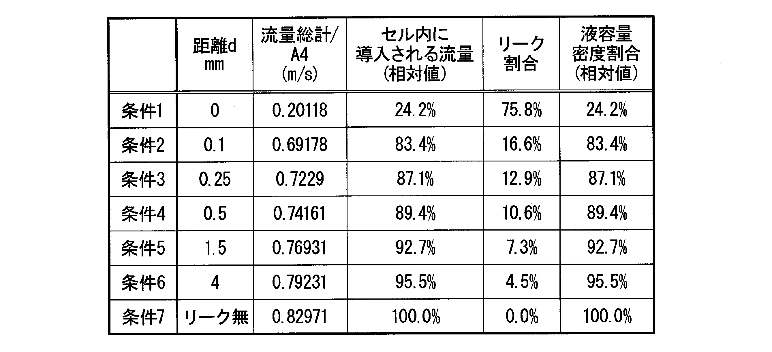
図7は、距離dとリーク割合との関係を示したグラフである。図7において、縦軸はリーク割合であり、横軸は距離dである。
図7に示すように、距離dが僅かでも大きくなると、リーク割合が激減する。このことから、上記の流体解析条件である場合にリーク割合を低減するには、距離dを0.10mm以上、4.00mm以下とすることが好ましく、0.25mm以上、2.00mm以下とすることがより好ましい。さらに、第2電極への電解液供給の均一性の点から、距離dを0.50mm以上、1.50mm以下とすることが望ましい。
図7に示すように、距離dが僅かでも大きくなると、リーク割合が激減する。このことから、上記の流体解析条件である場合にリーク割合を低減するには、距離dを0.10mm以上、4.00mm以下とすることが好ましく、0.25mm以上、2.00mm以下とすることがより好ましい。さらに、第2電極への電解液供給の均一性の点から、距離dを0.50mm以上、1.50mm以下とすることが望ましい。
「液容量密度の算出」
下記式を用いて、セル内に導入される流量(Q2)を導入全流量(Q)で除して液容量密度(相対値)を算出した。その結果を表2および図9に示す。
下記式を用いて、セル内に導入される流量(Q2)を導入全流量(Q)で除して液容量密度(相対値)を算出した。その結果を表2および図9に示す。

図8は、距離dと液容量密度(相対値)との関係を示したグラフである。図8において、縦軸は液容量密度(相対値)であり、横軸は距離dである。
図8に示すように、距離dが僅かでも大きくなると、液容量密度(相対値)が激増する。このことから、上記の流体解析条件である場合に液容量密度(相対値)を高くするには、距離dを0.10mm以上、4.00mm以下とすることが好ましく、0.25mm以上、2.00mm以下とすることがより好ましい。さらに、第2電極への電解液供給の均一性の点から、距離dを0.50mm以上、1.50mm以下とすることが望ましい。
図8に示すように、距離dが僅かでも大きくなると、液容量密度(相対値)が激増する。このことから、上記の流体解析条件である場合に液容量密度(相対値)を高くするには、距離dを0.10mm以上、4.00mm以下とすることが好ましく、0.25mm以上、2.00mm以下とすることがより好ましい。さらに、第2電極への電解液供給の均一性の点から、距離dを0.50mm以上、1.50mm以下とすることが望ましい。
「セル抵抗率の算出」
セル抵抗率〔Ω・cm2〕は、充放電を行って充放電曲線を得た後に、中点法を用いて、以下の式(4)から算出した。充電と放電は同じ電流で行う。
ρS,cell = S ×(V1-V2)/(2×I) ・・・(4)
ここで、
ρS,cell:セル抵抗率〔Ω・cm2〕
S:電極面積〔cm2〕
V1:充電曲線の中点電圧〔V〕
V2:放電曲線の中点電圧〔V〕
I:充放電電流〔A〕
である。
セル抵抗率〔Ω・cm2〕は、充放電を行って充放電曲線を得た後に、中点法を用いて、以下の式(4)から算出した。充電と放電は同じ電流で行う。
ρS,cell = S ×(V1-V2)/(2×I) ・・・(4)
ここで、
ρS,cell:セル抵抗率〔Ω・cm2〕
S:電極面積〔cm2〕
V1:充電曲線の中点電圧〔V〕
V2:放電曲線の中点電圧〔V〕
I:充放電電流〔A〕
である。
この算出方法をより詳細に説明する。
充放電曲線では必ず、充電曲線が上になり、放電曲線が下になる。これは、電池の内部抵抗に起因する。すなわち、放電の際には、開放端電圧(電流が流れていないときの電圧)に対して、電池の内部抵抗の分の電圧降下(過電圧)分が放電電圧となる。
一方、充電は開放端電圧に対して、電池の内部抵抗の分の電圧上昇(過電圧)分が充電電圧となる。これを式にすると;
充電電圧(V)=開放端電圧(V)+過電圧(V) ・・・(1-a)
放電電圧(V)=開放端電圧(V)-過電圧(V) ・・・(1-b)
過電圧(V)=電池の内部抵抗(Ω)×充放電電流(I) ・・・(1-c)
(1-a)~(1-c)から、
電池の内部抵抗(Ω)={充電電圧(V)-放電電圧(V)}/2×充放電電流(I)、が得られる。ここで、充放電電流(I)を電流密度にすると、セル抵抗率〔Ω・cm2〕の式が得られる。
ここで、充放電曲線(横軸:電気容量(Ah)、縦軸:電池電圧(V))において、充電曲線から得られた充電容量の1/2での電圧(V1)を充電電圧とし、及び、放電曲線から得られた放電容量の1/2での電圧(V2)を放電電圧としたものが中点法によるセル抵抗率〔Ω・cm2〕の算出方法である。
本発明の集電板ユニットを備えるレドックスフロー電池では、循環する電解液を効果的に電極に供給できる。このため、本発明のレドックスフロー電池では、充放電時に電極を効率よく最大限利用できる。したがって、本発明のレドックスフロー電池は、大容量蓄電池のレドックスフロー電池として好適である。
10 イオン交換膜、20 集電板、20A 凹部、21 周縁壁、21a 第1面、21i 集電板流入口、22 内部壁、22a 内部壁の第1面、
23、24 集電板排出路、23a 起点、23b 集電板排出口、30 電極、31 第1電極、32 第2電極、33 液流出層、40 セルフレーム、
51 シール部材、52 隙間、53 セルフレーム供給管、
53a フレーム開口部、54 溝、57 セルフレーム排出路、
100 レドックスフロー電池、200 集電板ユニット、201 外周面、
201a 第1外周面、201b 第2外周面、CE セル、C 流路、
C1 第1流路、C2 第2流路、C3 集電板供給管
23、24 集電板排出路、23a 起点、23b 集電板排出口、30 電極、31 第1電極、32 第2電極、33 液流出層、40 セルフレーム、
51 シール部材、52 隙間、53 セルフレーム供給管、
53a フレーム開口部、54 溝、57 セルフレーム排出路、
100 レドックスフロー電池、200 集電板ユニット、201 外周面、
201a 第1外周面、201b 第2外周面、CE セル、C 流路、
C1 第1流路、C2 第2流路、C3 集電板供給管
Claims (11)
- イオン交換膜と集電板との間に配置された電極と、前記集電板および前記電極の外周面を囲む枠状のセルフレームとを有するレドックスフロー電池に用いられる集電板ユニットであり、
前記集電板ユニットは、前記集電板と前記セルフレームとが一体化されてなり、
前記集電板は、前記電極との対向面に凹状に形成された溝からなる流路と、前記集電板を貫通して前記流路に電解液を供給する集電板供給管とを有し、前記集電板供給管は、前記セルフレームと対向する前記外周面に開口された集電板流入口を有し、
前記セルフレームの前記集電板流入口との対向面には、前記集電板流入口に前記電解液を供給するフレーム開口部が設けられ、
前記集電板流入口と前記フレーム開口部とが、シール部材を介して接合されている集電板ユニット。 - 前記セルフレームの前記集電板流入口との対向面に、前記シール部材の断面積よりも広い面積を有し、前記シール部材よりも厚みの薄い溝が設けられている請求項1に記載の集電板ユニット。
- 前記集電板は、平面視矩形であり、
前記集電板の前記電極との対向面の縁部に沿って、前記電解液を排出する集電板排出路が設けられ、
前記集電板排出路は、前記集電板流入口が開口されている第1外周面と平面視で並行に配置された第2外周面に集電板排出口を有し、前記集電板排出路の起点は、前記第1外周面と平面視で離間する位置に配置されている請求項1または請求項2に記載の集電板ユニット。 - 前記電極は、前記集電板側から順に、第1電極と、第2電極と、液流出層とが積層されており、前記第1電極および前記液流出層の通液性が前記第2電極よりも高い請求項3に記載の集電板ユニット。
- 前記第2電極の側面および前記液流出層の集電板側の面が、前記集電板排出路の内壁の一部を兼ねる請求項4に記載の集電板ユニット。
- 前記集電板排出路の起点と、前記第1外周面との平面視での距離が、前記第2電極の厚み以上である請求項5に記載の集電板ユニット。
- 前記集電板の前記電極との対向面であって縁部から離間した領域に、前記電極が収納される凹部が設けられ、前記凹部の底面に前記流路が配置されている請求項1~請求項6のいずれか一項に記載の集電板ユニット。
- 前記凹部の深さが、前記電極の厚さ以下である請求項7に記載の集電板ユニット。
- 前記集電板排出路が、前記集電板の平行な2辺にそれぞれ設けられている請求項3~請求項8のいずれか一項に記載の集電板ユニット。
- 前記集電板排出路の起点と、前記第1外周面との平面視での距離が、0.25mm以上4mm以下である請求項3~請求項9のいずれか一項に記載の集電板ユニット。
- イオン交換膜と集電板との間に配置された電極と、前記集電板の外周面を囲む枠状のセルフレームとを有するレドックスフロー電池であり、
前記集電板および前記セルフレームとして、請求項1~請求項10のいずれか一項に記載の集電板ユニットが備えられているレドックスフロー電池。
Applications Claiming Priority (2)
| Application Number | Priority Date | Filing Date | Title |
|---|---|---|---|
| JP2018244992 | 2018-12-27 | ||
| JP2018-244992 | 2018-12-27 |
Publications (1)
| Publication Number | Publication Date |
|---|---|
| WO2020138049A1 true WO2020138049A1 (ja) | 2020-07-02 |
Family
ID=71125757
Family Applications (1)
| Application Number | Title | Priority Date | Filing Date |
|---|---|---|---|
| PCT/JP2019/050548 WO2020138049A1 (ja) | 2018-12-27 | 2019-12-24 | 集電板ユニットおよびレドックスフロー電池 |
Country Status (1)
| Country | Link |
|---|---|
| WO (1) | WO2020138049A1 (ja) |
Citations (6)
| Publication number | Priority date | Publication date | Assignee | Title |
|---|---|---|---|---|
| JP2012099368A (ja) * | 2010-11-02 | 2012-05-24 | Sumitomo Electric Ind Ltd | セルスタック、セルフレーム、レドックスフロー電池、およびセルスタックの製造方法 |
| WO2016072192A1 (ja) * | 2014-11-06 | 2016-05-12 | 住友電気工業株式会社 | 電池セル、およびレドックスフロー電池 |
| WO2018026005A1 (ja) * | 2016-08-04 | 2018-02-08 | 昭和電工株式会社 | レドックスフロー電池 |
| WO2018062356A1 (ja) * | 2016-09-30 | 2018-04-05 | 昭和電工株式会社 | レドックスフロー電池 |
| WO2018105648A1 (ja) * | 2016-12-06 | 2018-06-14 | 昭和電工株式会社 | 集電板及びレドックスフロー電池 |
| JP2018107080A (ja) * | 2016-12-28 | 2018-07-05 | 昭和電工株式会社 | レドックスフロー電池の製造方法 |
-
2019
- 2019-12-24 WO PCT/JP2019/050548 patent/WO2020138049A1/ja active Application Filing
Patent Citations (6)
| Publication number | Priority date | Publication date | Assignee | Title |
|---|---|---|---|---|
| JP2012099368A (ja) * | 2010-11-02 | 2012-05-24 | Sumitomo Electric Ind Ltd | セルスタック、セルフレーム、レドックスフロー電池、およびセルスタックの製造方法 |
| WO2016072192A1 (ja) * | 2014-11-06 | 2016-05-12 | 住友電気工業株式会社 | 電池セル、およびレドックスフロー電池 |
| WO2018026005A1 (ja) * | 2016-08-04 | 2018-02-08 | 昭和電工株式会社 | レドックスフロー電池 |
| WO2018062356A1 (ja) * | 2016-09-30 | 2018-04-05 | 昭和電工株式会社 | レドックスフロー電池 |
| WO2018105648A1 (ja) * | 2016-12-06 | 2018-06-14 | 昭和電工株式会社 | 集電板及びレドックスフロー電池 |
| JP2018107080A (ja) * | 2016-12-28 | 2018-07-05 | 昭和電工株式会社 | レドックスフロー電池の製造方法 |
Similar Documents
| Publication | Publication Date | Title |
|---|---|---|
| EP3346537B1 (en) | Bipolar plate, cell frame and cell stack, and redox flow battery | |
| JP5582193B2 (ja) | 燃料電池用セパレータ、燃料電池、燃料電池の製造方法 | |
| WO2015162954A1 (ja) | 双極板、レドックスフロー電池、及び双極板の製造方法 | |
| US11476472B2 (en) | Separator plate for an electrochemical system | |
| WO2016072191A1 (ja) | 電池セル、およびレドックスフロー電池 | |
| TWI648903B (zh) | 氧化還原液流電池 | |
| WO2018105648A1 (ja) | 集電板及びレドックスフロー電池 | |
| TW201830760A (zh) | 氧化還原液流電池 | |
| JPWO2018116467A1 (ja) | セルフレーム、セルスタック、およびレドックスフロー電池 | |
| KR102173663B1 (ko) | 연료 전지 셀 | |
| WO2018105646A1 (ja) | 集電板及びレドックスフロー電池 | |
| WO2020138049A1 (ja) | 集電板ユニットおよびレドックスフロー電池 | |
| JP2020107481A (ja) | 集電板ユニットおよびレドックスフロー電池 | |
| WO2020158624A1 (ja) | 電池セル、セルスタック、及びレドックスフロー電池 | |
| WO2020158623A1 (ja) | 電池セル、セルスタック、及びレドックスフロー電池 | |
| WO2018105647A1 (ja) | 集電板及びレドックスフロー電池 | |
| WO2018105634A1 (ja) | 集電板及びレドックスフロー電池 | |
| WO2020158625A1 (ja) | 電池セル、セルスタック、及びレドックスフロー電池 | |
| JP2014241222A (ja) | 燃料電池 | |
| CN112771700B (zh) | 流体引导流路及具备该流体引导流路的燃料电池 | |
| JP2013222698A (ja) | 燃料電池 | |
| JP5781969B2 (ja) | 燃料電池 | |
| CN116565254A (zh) | 一种燃料电池 | |
| JP2020129502A (ja) | 電池セル、セルスタック、及びレドックスフロー電池 | |
| JP2020123530A (ja) | 燃料電池 |
Legal Events
| Date | Code | Title | Description |
|---|---|---|---|
| 121 | Ep: the epo has been informed by wipo that ep was designated in this application |
Ref document number: 19901631 Country of ref document: EP Kind code of ref document: A1 |
|
| NENP | Non-entry into the national phase |
Ref country code: DE |
|
| 122 | Ep: pct application non-entry in european phase |
Ref document number: 19901631 Country of ref document: EP Kind code of ref document: A1 |
|
| NENP | Non-entry into the national phase |
Ref country code: JP |