WO2020137858A1 - 車両搭載機器の制御装置 - Google Patents
車両搭載機器の制御装置 Download PDFInfo
- Publication number
- WO2020137858A1 WO2020137858A1 PCT/JP2019/050046 JP2019050046W WO2020137858A1 WO 2020137858 A1 WO2020137858 A1 WO 2020137858A1 JP 2019050046 W JP2019050046 W JP 2019050046W WO 2020137858 A1 WO2020137858 A1 WO 2020137858A1
- Authority
- WO
- WIPO (PCT)
- Prior art keywords
- data
- sensor
- sensor data
- microprocessor
- unit
- Prior art date
- Legal status (The legal status is an assumption and is not a legal conclusion. Google has not performed a legal analysis and makes no representation as to the accuracy of the status listed.)
- Ceased
Links
Images


Classifications
-
- B—PERFORMING OPERATIONS; TRANSPORTING
- B60—VEHICLES IN GENERAL
- B60W—CONJOINT CONTROL OF VEHICLE SUB-UNITS OF DIFFERENT TYPE OR DIFFERENT FUNCTION; CONTROL SYSTEMS SPECIALLY ADAPTED FOR HYBRID VEHICLES; ROAD VEHICLE DRIVE CONTROL SYSTEMS FOR PURPOSES NOT RELATED TO THE CONTROL OF A PARTICULAR SUB-UNIT
- B60W50/00—Details of control systems for road vehicle drive control not related to the control of a particular sub-unit, e.g. process diagnostic or vehicle driver interfaces
- B60W50/02—Ensuring safety in case of control system failures, e.g. by diagnosing, circumventing or fixing failures
- B60W50/0205—Diagnosing or detecting failures; Failure detection models
-
- B—PERFORMING OPERATIONS; TRANSPORTING
- B60—VEHICLES IN GENERAL
- B60W—CONJOINT CONTROL OF VEHICLE SUB-UNITS OF DIFFERENT TYPE OR DIFFERENT FUNCTION; CONTROL SYSTEMS SPECIALLY ADAPTED FOR HYBRID VEHICLES; ROAD VEHICLE DRIVE CONTROL SYSTEMS FOR PURPOSES NOT RELATED TO THE CONTROL OF A PARTICULAR SUB-UNIT
- B60W40/00—Estimation or calculation of non-directly measurable driving parameters for road vehicle drive control systems not related to the control of a particular sub unit, e.g. by using mathematical models
- B60W40/08—Estimation or calculation of non-directly measurable driving parameters for road vehicle drive control systems not related to the control of a particular sub unit, e.g. by using mathematical models related to drivers or passengers
- B60W40/09—Driving style or behaviour
-
- B—PERFORMING OPERATIONS; TRANSPORTING
- B62—LAND VEHICLES FOR TRAVELLING OTHERWISE THAN ON RAILS
- B62D—MOTOR VEHICLES; TRAILERS
- B62D5/00—Power-assisted or power-driven steering
- B62D5/04—Power-assisted or power-driven steering electrical, e.g. using an electric servo-motor connected to, or forming part of, the steering gear
- B62D5/0457—Power-assisted or power-driven steering electrical, e.g. using an electric servo-motor connected to, or forming part of, the steering gear characterised by control features of the drive means as such
- B62D5/0481—Power-assisted or power-driven steering electrical, e.g. using an electric servo-motor connected to, or forming part of, the steering gear characterised by control features of the drive means as such monitoring the steering system, e.g. failures
- B62D5/0484—Power-assisted or power-driven steering electrical, e.g. using an electric servo-motor connected to, or forming part of, the steering gear characterised by control features of the drive means as such monitoring the steering system, e.g. failures for reaction to failures, e.g. limp home
-
- B—PERFORMING OPERATIONS; TRANSPORTING
- B62—LAND VEHICLES FOR TRAVELLING OTHERWISE THAN ON RAILS
- B62D—MOTOR VEHICLES; TRAILERS
- B62D5/00—Power-assisted or power-driven steering
- B62D5/04—Power-assisted or power-driven steering electrical, e.g. using an electric servo-motor connected to, or forming part of, the steering gear
- B62D5/0457—Power-assisted or power-driven steering electrical, e.g. using an electric servo-motor connected to, or forming part of, the steering gear characterised by control features of the drive means as such
- B62D5/0481—Power-assisted or power-driven steering electrical, e.g. using an electric servo-motor connected to, or forming part of, the steering gear characterised by control features of the drive means as such monitoring the steering system, e.g. failures
- B62D5/049—Power-assisted or power-driven steering electrical, e.g. using an electric servo-motor connected to, or forming part of, the steering gear characterised by control features of the drive means as such monitoring the steering system, e.g. failures detecting sensor failures
-
- G—PHYSICS
- G01—MEASURING; TESTING
- G01D—MEASURING NOT SPECIALLY ADAPTED FOR A SPECIFIC VARIABLE; ARRANGEMENTS FOR MEASURING TWO OR MORE VARIABLES NOT COVERED IN A SINGLE OTHER SUBCLASS; TARIFF METERING APPARATUS; MEASURING OR TESTING NOT OTHERWISE PROVIDED FOR
- G01D3/00—Indicating or recording apparatus with provision for the special purposes referred to in the subgroups
- G01D3/028—Indicating or recording apparatus with provision for the special purposes referred to in the subgroups mitigating undesired influences, e.g. temperature, pressure
- G01D3/036—Indicating or recording apparatus with provision for the special purposes referred to in the subgroups mitigating undesired influences, e.g. temperature, pressure on measuring arrangements themselves
- G01D3/0365—Indicating or recording apparatus with provision for the special purposes referred to in the subgroups mitigating undesired influences, e.g. temperature, pressure on measuring arrangements themselves the undesired influence being measured using a separate sensor, which produces an influence related signal
-
- G—PHYSICS
- G01—MEASURING; TESTING
- G01L—MEASURING FORCE, STRESS, TORQUE, WORK, MECHANICAL POWER, MECHANICAL EFFICIENCY, OR FLUID PRESSURE
- G01L25/00—Testing or calibrating of apparatus for measuring force, torque, work, mechanical power, or mechanical efficiency
- G01L25/003—Testing or calibrating of apparatus for measuring force, torque, work, mechanical power, or mechanical efficiency for measuring torque
-
- G—PHYSICS
- G01—MEASURING; TESTING
- G01L—MEASURING FORCE, STRESS, TORQUE, WORK, MECHANICAL POWER, MECHANICAL EFFICIENCY, OR FLUID PRESSURE
- G01L5/00—Apparatus for, or methods of, measuring force, work, mechanical power, or torque, specially adapted for specific purposes
- G01L5/22—Apparatus for, or methods of, measuring force, work, mechanical power, or torque, specially adapted for specific purposes for measuring the force applied to control members, e.g. control members of vehicles, triggers
- G01L5/221—Apparatus for, or methods of, measuring force, work, mechanical power, or torque, specially adapted for specific purposes for measuring the force applied to control members, e.g. control members of vehicles, triggers to steering wheels, e.g. for power assisted steering
-
- B—PERFORMING OPERATIONS; TRANSPORTING
- B60—VEHICLES IN GENERAL
- B60W—CONJOINT CONTROL OF VEHICLE SUB-UNITS OF DIFFERENT TYPE OR DIFFERENT FUNCTION; CONTROL SYSTEMS SPECIALLY ADAPTED FOR HYBRID VEHICLES; ROAD VEHICLE DRIVE CONTROL SYSTEMS FOR PURPOSES NOT RELATED TO THE CONTROL OF A PARTICULAR SUB-UNIT
- B60W50/00—Details of control systems for road vehicle drive control not related to the control of a particular sub-unit, e.g. process diagnostic or vehicle driver interfaces
- B60W50/02—Ensuring safety in case of control system failures, e.g. by diagnosing, circumventing or fixing failures
- B60W50/0205—Diagnosing or detecting failures; Failure detection models
- B60W2050/0215—Sensor drifts or sensor failures
Definitions
- the present invention relates to a control device for a vehicle-mounted device.
- Patent Document 1 discloses a power steering device having a plurality of sensors, a plurality of microprocessors, and the same number of output devices as the plurality of microprocessors.
- a control device for a vehicle-mounted device is a sensor unit, and includes a first sensor and a second sensor, the first sensor detecting a driving state of a vehicle, and the first sensor.
- a sensor unit that outputs data, the second sensor detects a driving state of the vehicle that is the same detection target as the first sensor, and outputs second sensor data;
- a first microprocessor and a second microprocessor are included, the second microprocessor includes a second sensor data request signal generation unit, and the second sensor data request signal generation unit generates a second sensor data request signal.
- the second sensor data request signal includes information requesting the second sensor to transmit the second sensor data to the microprocessor unit, and the second sensor data request signal from the second microprocessor
- the first microprocessor is a data signal transmitted multiple times within a predetermined period, the first microprocessor, the first sensor data request signal generation unit, the first data comparison unit, the first abnormality determination And a first command signal generation unit, the first sensor data request signal generation unit generates a first sensor data request signal, the first sensor data request signal, the first to the microprocessor unit Includes information requesting the first sensor to transmit sensor data, the first microprocessor to the first sensor is a data signal transmitted multiple times within a predetermined period, the first The data comparison unit, in response to the second sensor data request signal, the first comparison data selected from the plurality of first sensor data transmitted to the microprocessor unit a plurality of times, and the second sensor.
- the second comparison data selected from the plurality of second sensor data transmitted a plurality of times to the microprocessor unit is compared, and the first abnormality determination unit Based on the comparison result of the first data comparison unit, to determine the presence or absence of abnormality of the sensor unit, the first command signal generation unit, based on the first sensor data, a first command signal for driving control of the actuator. Generating the microprocessor.
- FIG. 9 is a time chart showing a method of calculating an estimated value of one data in the redundant comparison of the second embodiment. 9 is a time chart showing an example of redundancy comparison according to the second embodiment.
- 7 is a configuration diagram of a control system of a steering device 1 of Embodiment 3.
- FIG. 9 is a configuration diagram of a control system of a steering device 1 according to a fourth embodiment.
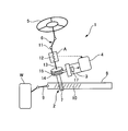
- FIG. 1 is a configuration diagram of a steering device diagram to which the present invention is applied.
- the steering device 1 (equipment mounted on a vehicle) is mounted on a vehicle powered by an engine.
- the steering device 1 has a steering mechanism 2, an electric motor (actuator) 3, and a control device 4.
- the steering mechanism 2 steers the front wheels W, which are steered wheels.
- the steering mechanism 2 has a steering wheel 5, a steering shaft 6, a pinion 7, a rack bar 8 and a tie rod 9.
- the steering torque input to the steering wheel 5 is transmitted from the steering shaft 6 to the pinion 7 and converted into thrust of the rack bar 8 by the rack 10 meshing with the pinion 7.
- the linear motion of the rack bar 8 is transmitted to the tie rods 9, and the front wheels W are steered.
- the steering shaft 6 has an input shaft 11, a torsion bar 12, and a pinion shaft 13.
- the input shaft 11 and the pinion shaft 13 can rotate relative to each other due to the torsion of the torsion bar
- the electric motor 3 is, for example, a three-phase brushless motor.
- the assist torque output from the electric motor 3 is transmitted to the pinion 7 via the worm shaft 14 and the worm wheel 15.
- the steering shaft 6 is provided with a sensor unit A that straddles the input shaft 11 and the pinion shaft 13 and detects steering torque.
- the sensor unit A has a plurality of torque sensors that detect the twist of the torsion bar 12, and is composed of at least a first torque sensor (first sensor) A1 and a second torque sensor (second sensor) A2 (FIG. 2).
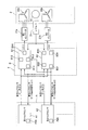
- FIG. 2 is a configuration diagram of a control system of the steering device 1.
- the electric motor 3 is a double three-phase brushless motor in which the first stator coil 20a and the second stator coil 20b are provided on the outer circumference of one rotor 19.
- the maximum motor output when only the first stator coil 20a is energized and the maximum motor output when only the second stator coil 20b is energized are the same.
- the electric motor 3 outputs the assist torque according to the current supplied from the first inverter 21a and the second inverter 21b.
- the microprocessor unit B constituting the control device 4 has a plurality of microprocessors, and includes a first microprocessor B1 that supplies power to the first stator coil 20a and a second microprocessor B1 that supplies power to the second stator coil 20b. It has a processor B2 and has at least two control systems.
- the first microprocessor B1 includes a first torque sensor data request signal generation unit (first sensor data request signal generation unit) B11, a first torque sensor data comparison unit (first data comparison unit) B12, and a first abnormality determination.
- the unit B13 and the first command signal generation unit B14 are provided.
- the first torque sensor data request signal generation unit B11 generates a first torque sensor data request signal (first sensor data request signal) ⁇ 1.
- the first torque sensor data comparison unit B12 outputs the plurality of first torque sensor data (first sensor data) ⁇ 1 transmitted a plurality of times to the first microprocessor B1 based on the first torque sensor data request signal ⁇ 1. Based on the one first comparison data ⁇ 1 selected from among the two and the second torque sensor data request signal (second sensor data request signal) ⁇ 2, the plurality of the plurality of first data transmitted to the first microprocessor B1 are transmitted a plurality of times. Redundant comparison is performed with one second comparison data ⁇ 2 selected from the two torque sensor data (second sensor data) ⁇ 2.
- the first torque sensor data comparison unit B12 may select two or more torque sensor data items from the plurality of first torque sensor data items ⁇ 1 and the plurality of second torque sensor data items ⁇ 2.
- the first abnormality determination unit B13 determines whether or not there is an abnormality in the sensor unit A based on the comparison result of the first torque sensor data comparison unit B12.
- the first command signal generator B14 generates a first command signal ⁇ 1 for driving and controlling the electric motor 3 based on the first torque sensor data ⁇ 1.
- the second microprocessor B2 includes a second torque sensor data request signal generation unit (second sensor data request signal generation unit) B21, a second torque sensor data comparison unit B22, a second abnormality determination unit B23, and a second command signal generation unit. It is equipped with B24.
- the second torque sensor data request signal generator B21 generates the second torque sensor data request signal ⁇ 2.
- the second torque sensor data comparison unit B22 selects one of the plurality of second torque sensor data ⁇ 2 transmitted a plurality of times to the second microprocessor B2 based on the second torque sensor data request signal ⁇ 2. One first selected from the plurality of first torque sensor data ⁇ 1 transmitted a plurality of times to the second microprocessor B2 based on the first first comparison data ⁇ 2 and the first torque sensor data request signal ⁇ 1. 1 Redundant comparison is made with the comparison data ⁇ 1.
- the second abnormality determination unit B23 determines whether or not there is an abnormality in the sensor unit A based on the comparison result of the second torque sensor data comparison unit B22.
- the second command signal generator B24 generates a second command signal ⁇ 2 for controlling the drive of the electric motor 3 based on the second torque sensor data ⁇ 2.
- the first torque sensor A1 and the second torque sensor A2 are also divided into two systems as described above.
- the first torque sensor A1 and the second torque sensor A2 respectively include a first torque sensor self-diagnosis unit (first sensor self-diagnosis unit) A1a and a second torque sensor that determine whether the first torque sensor A1 is abnormal.
- a second torque sensor self-diagnosis unit (second sensor self-diagnosis unit) A2a for determining whether or not there is an abnormality in A2 is provided.
- the first torque sensor data ⁇ 1 includes first self-diagnosis data ⁇ 1 which is a diagnosis result by the first torque sensor self-diagnosis unit A1a, and the second torque sensor data ⁇ 2 is diagnosed by the second torque sensor self-diagnosis unit A2a.
- the result includes the second self-diagnosis data ⁇ 2. Therefore, the first torque sensor data comparison unit B12 and the second torque sensor data comparison unit B22 use the first torque sensor data ⁇ 1 including the first self-diagnosis data ⁇ 1 indicating the abnormality of the first torque sensor A1 as the first comparison data.
- the second torque sensor data ⁇ 2 which is not selected as ⁇ 1 and includes the second self-diagnosis data ⁇ 2 indicating the abnormality of the second torque sensor A2, is not selected as the second comparison data ⁇ 2. Accordingly, in the first torque sensor data comparison unit B12 and the second torque sensor data comparison unit B22, unnecessary calculation load can be reduced, and since the comparison is not performed based on the abnormality data, the first abnormality determination unit B13. And the risk of erroneous determination in the second abnormality determination unit B23 can be further reduced.
- the first torque sensor A1 outputs a first torque sensor data signal ⁇ 1 corresponding to the steering torque to the first microprocessor B1 and the second microprocessor B2.
- the second torque sensor A2 outputs a second torque sensor data signal ⁇ 2 corresponding to the steering torque to the second microprocessor B2 and the first microprocessor B1.
- a resolver 17 that detects the rotation angle of the rotor 19 is installed inside the electric motor 3.
- the resolver 17 outputs a motor rotation angle signal according to the rotation angle of the rotor 19 to the first microprocessor B1 and the second microprocessor B2.
- the first microprocessor B1 and the second microprocessor B2 of the microprocessor unit B calculate the target assist torque according to the torque signal, the motor rotation angle signal, and other signals indicating the vehicle state (vehicle speed signal, etc.), and drive the motor.
- Power steering control is performed to control the electric power supplied to the electric motor 3 so that the output torque of the motor 3 becomes the target assist torque. That is, the first microprocessor B1 outputs the first command signal ⁇ 1 generated by the first command signal generator B14 to the first inverter 21a, and the second microprocessor B2 is generated by the second command signal generator B24.
- the electric power supplied to the electric motor 3 is controlled by outputting the generated second command signal ⁇ 2 to the second inverter 21b.
- the inverters 21a and 21b convert DC power from a battery (not shown) into AC power based on the command signals ⁇ 1 and ⁇ 2, and supply the AC power to the first stator coil 20a and the second stator coil 20b of the electric motor 3.
- Each of the inverters 21a and 21b has a three-phase bridge circuit using two MOSFETs, which are switching elements, for each phase. ON/OFF of each MOSFET is controlled by a motor command signal input to the control terminal (gate terminal) of the MOSFET.
- the first torque sensor A1 and the second torque sensor A2 of the sensor unit A are, for example, magnetostrictive type and have a Hall IC that outputs a torque signal according to the steering torque.
- the first torque sensor A1 and the second torque sensor A2 of the sensor unit A hold the analog signal output from the Hall IC at a predetermined cycle, encode the digital signal into the first microprocessor B1 and the second microprocessor B2.
- the first torque sensor A1 and the second torque sensor A2 of the sensor unit A encode the analog signal into a SENT message based on the so-called SENT (Single Edge Nibble Transmission) protocol that complies with the American Society of Automotive Engineers standard SAE-J2716. Output.
- SENT Single Edge Nibble Transmission
- the SENT protocol is an asynchronous serial communication in which a transmitter (sensor) connects to a receiver (microprocessor unit B) on a point-to-point basis. That is, when the first torque sensor A1 receives the first torque sensor data request signal ⁇ 1 from the first microprocessor B1 which is a data signal transmitted a plurality of times within a predetermined period, the first torque sensor A1 receives the signal. The timing first torque sensor data ⁇ 1 is transmitted to the first microprocessor B1 and the second microprocessor B2. Similarly, when the second torque sensor A2 receives the second torque sensor data request signal ⁇ 2 from the second microprocessor B2, which is a data signal transmitted a plurality of times within a predetermined period, the second torque sensor A2 receives the reception. The second torque sensor data ⁇ 2 having the above timing is transmitted to the second microprocessor B2 and the first microprocessor B1. The second torque sensor data request signal ⁇ 2 from the second microprocessor B2 is also transmitted to the first microprocessor B1.
- the first torque sensor data comparison unit B12 detects the first torque sensor data ⁇ 1 of the first torque sensor A1 and the second torque sensor data ⁇ 2 of the second torque sensor A2 based on the second torque sensor data request signal ⁇ 2.
- the first comparison data ⁇ 1 and the second comparison data ⁇ 2, which are the sensor data having the closest timings, are redundantly compared. It is preferable to compare the closest torque sensor data with each other, but it is not always necessary to compare the closest torque sensor data with each other. As a result, it is possible to reduce the risk that the first abnormality determination unit B13 makes an erroneous determination that the sensor unit A is abnormal, although the first torque sensor A1 and the second torque sensor A2 are normal. ..
- control device for a vehicle-mounted device has the operational effects listed below.
- the first torque sensor data comparison unit B12 of the first microprocessor B1 is based on the second torque sensor data request signal ⁇ 2, and the sensor data of the detection timings of the first torque sensor A1 and the second torque sensor A2 are close to each other.
- the first comparison data ⁇ 1 and the second comparison data ⁇ 2 are redundantly compared. Therefore, although the first torque sensor A1 and the second torque sensor A2 are normal, it is possible to reduce the risk that the first abnormality determination unit B13 makes an erroneous determination that the sensor unit A is abnormal.
- the first torque sensor data comparison unit B12 of the first microprocessor B1 and the second torque sensor data comparison unit B22 of the second microprocessor B2 output the first self-diagnosis data ⁇ 1 indicating an abnormality of the first torque sensor A1.
- the first torque sensor data signal ⁇ 1 including the second torque sensor data ⁇ 1 is not selected as the first comparison data ⁇ 1
- the second torque sensor data ⁇ 2 including the second self-diagnosis data ⁇ 2 indicating the abnormality of the second torque sensor A2 is the second comparison data. It was not selected as ⁇ 2.
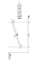
- FIG. 3 is a time chart showing a method of calculating an estimated value of one data in the redundant comparison of the second embodiment.
- the vertical axis represents the torque sensor data value
- the horizontal axis represents time.
- the first torque sensor data comparison unit B12 based on the second torque sensor data request signal ⁇ 2, the first torque sensor data ⁇ 1 of the first torque sensor A1 and the second torque sensor data of the second torque sensor A2.
- the first comparison data ⁇ 1 and the second comparison data ⁇ 2 which are torque sensor data whose ⁇ 2 detection timings are close to each other, are compared
- the first torque sensor data comparison unit B12 is the first microprocessor B1.
- the timing t2 (T1) at which the second torque sensor A2 outputs the second torque sensor data 1 ⁇ 2 as the second comparison data ⁇ 2 is estimated based on the timing at which the second torque sensor data request signal ⁇ 2 is received. Further, the first torque sensor data comparison unit B12 linearly interpolates between the first torque sensor data 1 ⁇ 1 at the timing t1 and the first torque sensor data 2 ⁇ 1 at the timing t3, so that the first comparison data ⁇ 1 corresponding to the timing t2. Estimate and generate. Since the other configurations are the same as those of the first embodiment, the same reference numerals are given to the same configurations and the description thereof will be omitted.
- the estimated and generated first comparison data ⁇ 1 and the second torque sensor data 1 ⁇ 2 as the second comparison data ⁇ 2 are redundantly compared.
- the first torque sensor data request generation unit B11 changes the first torque sensor data request signal ⁇ 1 to the first torque based on the reception of the second torque sensor data request signal ⁇ 2 by the first microprocessor B1.
- the first torque sensor data ⁇ 1 at the timing t2 may be acquired by transmitting to the sensor A1. Accordingly, even when each of the first microprocessor B1 and the second microprocessor B2 outputs the first torque sensor data request signal ⁇ 1 and the second torque sensor data request signal ⁇ 2 at its own timing, it is appropriate.
- the first comparison data ⁇ 1 and the second comparison data ⁇ 2 can be selected, and the detection timings of the first comparison data ⁇ 1 and the second comparison data ⁇ 2 can be brought closer to each other, thereby increasing the risk of erroneous determination in the first abnormality determination unit B13. It can be further reduced.
- FIG. 4 is a time chart showing an example of redundancy comparison according to the second embodiment.
- the vertical axis represents the torque sensor data value, and the horizontal axis represents time.
- the time-series data of the first torque sensor data ⁇ 1 transmitted within the predetermined period is set to three data including the first torque sensor data 1 ⁇ 1 to the first torque sensor data 3 ⁇ 1 and similarly transmitted within the predetermined period.
- the time-series data of the second torque sensor data ⁇ 2 is set to three data including the second torque sensor data 1 ⁇ 2 and the second torque sensor data 3 ⁇ 2.
- the first torque sensor data comparison unit B12 selects the second torque sensor data 1 ⁇ 2 at the timing tb as the second comparison data ⁇ 2 based on the second torque sensor data request signal ⁇ 2, and all the data of the second torque sensor data 1 ⁇ 2.
- the first torque sensor data comparison unit B12 waits until the first microprocessor B1 acquires all the data of the second torque sensor data 1 ⁇ 2 (timing t ⁇ ).
- the first torque sensor data 1 ⁇ 1 at the timing ta and the first torque sensor data 2 ⁇ 1 at the timing tc are linearly interpolated and estimated, and the generated first comparison data ⁇ 1 at the timing tb and the second comparison data ⁇ 1 at the timing tb are generated.
- the second torque sensor data 1 ⁇ 2 as the comparison data ⁇ 2 is compared.
- the signal transmission method is SENT
- the first microprocessor B1 causes the second torque sensor to operate at the detection timing tc of the first torque sensor data 2 ⁇ 1.
- the first torque sensor data comparison unit B12 Since the first torque sensor data ⁇ 1 and the second torque sensor data ⁇ 2 are compared with each other, it is possible to suppress omission of the comparison data ⁇ .
- the control device for a vehicle-mounted device has the following operation effects in addition to the operation effects of the first embodiment.
- the first torque sensor data comparison unit B12 linearly interpolates between the first torque sensor data 1 ⁇ 1 at the timing t1 and the first torque sensor data 2 ⁇ 1 at the timing t2 so as to correspond to the timing t2(T1). 1 comparison data ⁇ 1 is estimated and generated, and the estimated and generated first comparison data ⁇ 1 and the second torque sensor data 1 ⁇ 2 as the second comparison data ⁇ 2 are redundantly compared, or the first torque sensor data request generation is performed.
- the part B11 transmits the first torque sensor data request signal ⁇ 1 to the first torque sensor A1 based on the reception of the second torque sensor data request signal ⁇ 2 by the first microprocessor B1, and the timing t2 (T1) is reached.
- the first torque sensor data ⁇ 1 as the one comparison data ⁇ 1 is acquired and the redundant comparison is performed. Therefore, even when each of the first microprocessor B1 and the second microprocessor B2 outputs the first torque sensor data request signal ⁇ 1 and the second torque sensor data request signal ⁇ 2 at its own timing, it is appropriate.
- the first comparison data ⁇ 1 and the second comparison data ⁇ 2 can be selected, and the detection timings of the first comparison data ⁇ 1 and the second comparison data ⁇ 2 can be made closer to each other, further increasing the risk of erroneous determination in the first abnormality determination unit B13. It can be reduced.
- the first torque sensor data comparison unit B12 selects the second torque sensor data 1 ⁇ 2 as the second comparison data ⁇ 2 based on the second torque sensor data request signal ⁇ 2, and all the data of the second torque sensor data 1 ⁇ 2.
- the first torque sensor data comparison unit B12 waits for acquisition of all data of the second torque sensor data 1 ⁇ 2 by the first microprocessor B1 (timing t ⁇ ).
- the first torque sensor data 1 ⁇ 1 and the first torque sensor data 2 ⁇ 1 at the timing tc are linearly interpolated and estimated, and the second comparison data ⁇ 1 at the timing tb and the second comparison data ⁇ 2 at the timing tb are generated.
- the torque sensor data 1 ⁇ 2 was compared.
- the signal transmission method is SENT
- the first microprocessor B1 causes the second torque sensor data to be detected even at the detection timing tc of the first torque sensor data 2 ⁇ 1.
- the first microprocessor B1 waits for the acquisition of all the data of the second torque sensor data 1 ⁇ 2 (timing t ⁇ ), and then the first torque sensor data comparison unit B12 executes Since the redundant comparison between the torque sensor data ⁇ 1 and the second torque sensor data ⁇ 2 is performed, the omission of the comparison data ⁇ can be suppressed.
- FIG. 5 is a configuration diagram of a control system of the steering device 1 according to the third embodiment.
- the electric motor 3 is a triple three-phase brushless motor in which the first stator coil 20a, the second stator coil 20b, and the third stator coil 20c are provided on the outer circumference of one rotor 19.
- a torque sensor self-diagnosis unit A3a is provided, and a third torque sensor A3 that detects the twist of the torsion bar 12 and outputs the third torque sensor data (third sensor data) ⁇ 3 to the third microprocessor B3 is additionally provided. ing.
- the third microprocessor B3 also receives the first torque sensor data ⁇ 1, and the third torque sensor data comparison unit B32 redundantly compares the third torque sensor data ⁇ 3 and the first torque sensor data ⁇ 1.
- the first microprocessor B1 includes a third torque sensor data request signal generation unit (third sensor data request signal generation unit) B15, and the third torque sensor data request signal generation unit B15 is used for the third torque sensor data request.
- a signal (third sensor data request signal) ⁇ 3 is generated.
- the third torque sensor data request signal ⁇ 3 includes information requesting the third torque sensor A3 to transmit the third torque sensor data ⁇ 3 to the first microprocessor B1 and is a data signal transmitted a plurality of times within a predetermined period. Is.
- the first data comparison unit B12 selects the third comparison based on the third torque sensor data request signal ⁇ 3 from the plurality of third torque sensor data ⁇ 3 transmitted to the first microprocessor B1 a plurality of times.
- the data ⁇ 3 is redundantly compared with the first comparison data ⁇ 1 and the second comparison data ⁇ 2 to make a majority decision. Since the other configurations are the same as those of the first embodiment, the same reference numerals are given to the same configurations and the description thereof will be omitted. As a result, by making a majority decision among three or more comparison data ⁇ , it is possible to identify an abnormal point and perform drive control of the electric motor 3 based on normal data.
- the control device for a vehicle-mounted device has the following operation effects in addition to the operation effects of the first embodiment.
- the first data comparison unit B12 is selected from the plurality of third torque sensor data ⁇ 3 transmitted a plurality of times to the first microprocessor B1 based on the third torque sensor data request signal ⁇ 3.
- the third comparison data ⁇ 3 is redundantly compared with the first comparison data ⁇ 1 and the second comparison data ⁇ 2 to make a majority decision. Therefore, by making a majority decision among three or more pieces of comparison data ⁇ , it is possible to identify an abnormal point and perform drive control of the electric motor 3 based on normal data.
- FIG. 6 is a configuration diagram of a control system of the steering device 1 according to the fourth embodiment.
- the first torque sensor data request signal ⁇ 1 from the first torque sensor data request signal generation unit B11 of the first microprocessor B1 is not only the first torque sensor A1 but also the second microprocessor B2. Will also be sent. Since the other configurations are the same as those of the first embodiment, the same reference numerals are given to the same configurations and the description thereof will be omitted.
- the first torque sensor data request signal ⁇ 1 from the first torque sensor data request signal generator B11 of the first microprocessor B1 is transmitted not only to the first torque sensor A1 but also to the second microprocessor B2. I chose Therefore, in addition to the first microprocessor B1, in the second microprocessor B2 as well, although the first torque sensor A1 and the second torque sensor A2 are normal, the sensor unit A in the second abnormality determination unit B23 is If it is abnormal, the risk of misjudgment can be reduced.
- the present invention is not limited to the above-described embodiment, but includes various modifications.
- the above-described embodiments have been described in detail in order to explain the present invention in an easy-to-understand manner, and are not necessarily limited to those having all the configurations described.
- a part of the configuration of one embodiment can be replaced with the configuration of another embodiment, and the configuration of another embodiment can be added to the configuration of one embodiment.
- a sensor unit A1 first torque sensor (first sensor) A1a first torque sensor self-diagnosis unit (first sensor self-diagnosis unit) A2 second torque Sensor (second sensor) A2a Second torque sensor self-diagnosis unit (second sensor self-diagnosis unit) A3 Third torque sensor (third sensor) B Microprocessor unit B1, First microprocessor B11 First torque sensor data request signal generation Part (first sensor data request signal generation part) B12 first torque sensor data comparison part (first data comparison part) B13 first abnormality determination part B14 first command signal generation part B15 third torque sensor data request signal generation part ( Third sensor data request signal generation unit) B2 Second microprocessor B21 Second torque sensor data request signal generation unit (second sensor data request signal generation unit) B22 Second torque sensor data comparison unit (second data comparison unit) B23 Second abnormality determination unit B24 Second command signal generation unit B3 Third microprocessor B31 Third torque sensor data request signal generation unit (third sensor data request signal generation unit) B34 Third command signal signal
Landscapes
- Engineering & Computer Science (AREA)
- Automation & Control Theory (AREA)
- Mechanical Engineering (AREA)
- Transportation (AREA)
- Physics & Mathematics (AREA)
- General Physics & Mathematics (AREA)
- Human Computer Interaction (AREA)
- Chemical & Material Sciences (AREA)
- Combustion & Propulsion (AREA)
- Mathematical Physics (AREA)
- Steering Control In Accordance With Driving Conditions (AREA)
- Power Steering Mechanism (AREA)
- Force Measurement Appropriate To Specific Purposes (AREA)
- Testing Or Calibration Of Command Recording Devices (AREA)
Abstract
本発明の車両搭載機器の制御装置は、センサデータを出力する第1センサ、第2センサ、第1マイクロプロセッサ、第2マイクロプロセッサを備え、第2マイクロプロセッサの第2センサデータ要求信号生成部は、第2センサデータ要求信号を生成し、前記第1マイクロプロセッサは、第1センサデータ要求信号生成部と、第1データ比較部と、第1異常判断部と、第1指令信号生成部を含み、前記第1センサデータ要求信号生成部は、第1センサデータ要求信号を生成し、前記第1データ比較部は、複数の前記第1センサデータの中から選択された第1比較データと、複数の前記第2センサデータの中から選択された第2比較データと、を比較し、前記第1異常判断部は、前記第1データ比較部の比較結果に基づき、前記センサ部の異常の有無を判断するようにした。
Description
本発明は、車両搭載機器の制御装置に関する。
この種の技術としては、下記の特許文献1に記載の技術が開示されている。特許文献1には、複数のセンサ、複数のマイクロプロセッサおよび、複数のマイクロプロセッサの数と同数の出力装置を有するパワーステアリング装置が開示されている。
特許文献1に記載の技術では、複数のセンサの内、少なくとも1つの信号が、複数のマイクロプロセッサに共通に入力されている。
このため、それぞれのセンサの信号取得タイミングを1つのマイクロプロセッサによって制御することができないため、それぞれのマイクロプロセッサは、複数のセンサの同一時間のデータを取得することができないので、冗長比較するうえで、比較するデータの取得タイミングがずれてしまい、精度よく比較することができないといった課題が生じる。
このため、それぞれのセンサの信号取得タイミングを1つのマイクロプロセッサによって制御することができないため、それぞれのマイクロプロセッサは、複数のセンサの同一時間のデータを取得することができないので、冗長比較するうえで、比較するデータの取得タイミングがずれてしまい、精度よく比較することができないといった課題が生じる。
本発明の目的の一つは、精度を向上した冗長比較をすることができる車両搭載機器の制御装置を提供することを一つの目的とする。
本発明の一実施形態では、車両搭載機器の制御装置は、センサ部であって、第1センサと、第2センサを含み、前記第1センサは、車両の運転状態を検出し、第1センサデータを出力し、前記第2センサは、前記第1センサと同じ検出対象である前記車両の運転状態を検出し、第2センサデータを出力する、前記センサ部と、マイクロプロセッサ部であって、第1マイクロプロセッサと、第2マイクロプロセッサを含み、前記第2マイクロプロセッサは、第2センサデータ要求信号生成部を含み、前記第2センサデータ要求信号生成部は、第2センサデータ要求信号を生成し、前記第2センサデータ要求信号は、前記マイクロプロセッサ部に前記第2センサデータを送信するように前記第2センサに対して要求する情報を含み、前記第2マイクロプロセッサから前記第2センサおよび前記第1マイクロプロセッサに対し、所定期間内において複数回送信されるデータ信号であり、前記第1マイクロプロセッサは、第1センサデータ要求信号生成部と、第1データ比較部と、第1異常判断部と、第1指令信号生成部を含み、前記第1センサデータ要求信号生成部は、第1センサデータ要求信号を生成し、前記第1センサデータ要求信号は、前記マイクロプロセッサ部に前記第1センサデータを送信するように前記第1センサに対して要求する情報を含み、前記第1マイクロプロセッサから前記第1センサに対し、所定期間内において複数回送信されるデータ信号であり、前記第1データ比較部は、前記第2センサデータ要求信号に応じて、前記マイクロプロセッサ部に対し複数回送信された複数の前記第1センサデータの中から選択された第1比較データと、前記第2センサデータ要求信号に応じて、前記マイクロプロセッサ部に対し複数回送信された複数の前記第2センサデータの中から選択された第2比較データと、を比較し、前記第1異常判断部は、前記第1データ比較部の比較結果に基づき、前記センサ部の異常の有無を判断し、前記第1指令信号生成部は、前記第1センサデータに基づき、前記アクチュエータを駆動制御する第1指令信号を生成する、前記マイクロプロセッサと、を有する。
本発明の一実施形態では、車両搭載機器の制御装置は、センサ部であって、第1センサと、第2センサを含み、前記第1センサは、車両の運転状態を検出し、第1センサデータを出力し、前記第2センサは、前記第1センサと同じ検出対象である前記車両の運転状態を検出し、第2センサデータを出力する、前記センサ部と、マイクロプロセッサ部であって、第1マイクロプロセッサと、第2マイクロプロセッサを含み、前記第2マイクロプロセッサは、第2センサデータ要求信号生成部を含み、前記第2センサデータ要求信号生成部は、第2センサデータ要求信号を生成し、前記第2センサデータ要求信号は、前記マイクロプロセッサ部に前記第2センサデータを送信するように前記第2センサに対して要求する情報を含み、前記第2マイクロプロセッサから前記第2センサおよび前記第1マイクロプロセッサに対し、所定期間内において複数回送信されるデータ信号であり、前記第1マイクロプロセッサは、第1センサデータ要求信号生成部と、第1データ比較部と、第1異常判断部と、第1指令信号生成部を含み、前記第1センサデータ要求信号生成部は、第1センサデータ要求信号を生成し、前記第1センサデータ要求信号は、前記マイクロプロセッサ部に前記第1センサデータを送信するように前記第1センサに対して要求する情報を含み、前記第1マイクロプロセッサから前記第1センサに対し、所定期間内において複数回送信されるデータ信号であり、前記第1データ比較部は、前記第2センサデータ要求信号に応じて、前記マイクロプロセッサ部に対し複数回送信された複数の前記第1センサデータの中から選択された第1比較データと、前記第2センサデータ要求信号に応じて、前記マイクロプロセッサ部に対し複数回送信された複数の前記第2センサデータの中から選択された第2比較データと、を比較し、前記第1異常判断部は、前記第1データ比較部の比較結果に基づき、前記センサ部の異常の有無を判断し、前記第1指令信号生成部は、前記第1センサデータに基づき、前記アクチュエータを駆動制御する第1指令信号を生成する、前記マイクロプロセッサと、を有する。
よって、本発明の一実施形態によれば、精度を向上した冗長比較をすることができる。
〔実施形態1〕 図1は、本発明が適用されるステアリング装置図の構成図である。
ステアリング装置1(車両搭載機器)は、エンジンを動力源とする車両に搭載されている。ステアリング装置1は、操舵機構2、電動モータ(アクチュエータ)3および制御装置4を有する。
操舵機構2は、転舵輪である前輪Wを転舵させる。操舵機構2は、ステアリングホイール5、操舵軸6、ピニオン7、ラックバー8およびタイロッド9を有する。
ステアリングホイール5に入力された操舵トルクは、操舵軸6からピニオン7へ伝達され、ピニオン7と噛み合うラック10によりラックバー8の推力へ変換される。ラックバー8の直線運動はタイロッド9へ伝達され、前輪Wが転舵される。
操舵軸6は、インプットシャフト11、トーションバー12およびピニオンシャフト13を有する。インプットシャフト11およびピニオンシャフト13は、トーションバー12の捩れにより互いに相対回転可能である。
電動モータ3は、例えば、三相ブラシレスモータである。電動モータ3から出力されるアシストトルクは、ウォームシャフト14およびウォームホイール15を介してピニオン7へ伝達される。
操舵軸6には、インプットシャフト11とピニオンシャフト13とを跨ぎ、操舵トルクを検出するセンサ部Aが設置されている。
センサ部Aは、トーションバー12の捩れを検出する複数のトルクセンサを有し、少なくとも第1トルクセンサ(第1センサ)A1と第2トルクセンサ(第2センサ)A2から構成されている(図2参照)。
操舵軸6には、インプットシャフト11とピニオンシャフト13とを跨ぎ、操舵トルクを検出するセンサ部Aが設置されている。
センサ部Aは、トーションバー12の捩れを検出する複数のトルクセンサを有し、少なくとも第1トルクセンサ(第1センサ)A1と第2トルクセンサ(第2センサ)A2から構成されている(図2参照)。
[制御系の構成] 図2は、ステアリング装置1の制御系の構成図である。
電動モータ3は、1つのロータ19の外周に第1ステータコイル20aおよび第2ステータコイル20bが設けられた二重三相ブラシレスモータである。
第1ステータコイル20aのみを通電したときの最大モータ出力と、第2ステータコイル20bのみを通電したときの最大モータ出力は同一である。
電動モータ3は、第1インバータ21a、第2インバータ21bから供給される電流に応じてアシストトルクを出力する。
制御装置4を構成するマイクロプロセッサ部Bは、複数のマイクロプロセッサを有し、第1ステータコイル20aに電力を供給する第1マイクロプロセッサB1と、第2ステータコイル20bに電力を供給する第2マイクロプロセッサB2とを有して、少なくとも2つの制御系統を持つ。
なお、第1マイクロプロセッサB1は、第1トルクセンサデータ要求信号生成部(第1センサデータ要求信号生成部)B11、第1トルクセンサデータ比較部(第1データ比較部)B12、第1異常判断部B13、第1指令信号生成部B14を備えている。
第1トルクセンサデータ要求信号生成部B11は、第1トルクセンサデータ要求信号(第1センサデータ要求信号)α1を生成する。
第1トルクセンサデータ比較部B12は、第1トルクセンサデータ要求信号α1に基づき、第1マイクロプロセッサB1に対し、複数回、送信された複数の第1トルクセンサデータ(第1センサデータ)β1の中から選択された1つの第1比較データγ1と、第2トルクセンサデータ要求信号(第2センサデータ要求信号)α2に基づき、第1マイクロプロセッサB1に対し、複数回、送信された複数の第2トルクセンサデータ(第2センサデータ)β2の中から選択された1つの第2比較データγ2とを冗長比較する。
なお、第1トルクセンサデータ比較部B12は、複数の第1トルクセンサデータβ1、複数の第2トルクセンサデータβ2から、それぞれ2つ以上のトルクセンサデータを選択してもよい。
第1異常判断部B13は、第1トルクセンサデータ比較部B12の比較結果に基づき、センサ部Aの異常の有無を判断する。
第1指令信号生成部B14は、第1トルクセンサデータβ1に基づき、電動モータ3を駆動制御する第1指令信号δ1を生成する。
第2マイクロプロセッサB2は、第2トルクセンサデータ要求信号生成部(第2センサデータ要求信号生成部)B21、第2トルクセンサデータ比較部B22、第2異常判断部B23、第2指令信号生成部B24を備えている。
第2トルクセンサデータ要求信号生成部B21は、第2トルクセンサデータ要求信号α2を生成する。
第2トルクセンサデータ比較部B22は、第2トルクセンサデータ要求信号α2に基づき、第2マイクロプロセッサB2に対し、複数回、送信された複数の第2トルクセンサデータβ2の中から選択された1つの第1比較データγ2と、第1トルクセンサデータ要求信号α1に基づき、第2マイクロプロセッサB2に対し、複数回、送信された複数の第1トルクセンサデータβ1の中から選択された1つの第1比較データγ1とを冗長比較する。
第2異常判断部B23は、第2トルクセンサデータ比較部B22の比較結果に基づき、センサ部Aの異常の有無を判断する。
第2指令信号生成部B24は、第2トルクセンサデータβ2に基づき、電動モータ3を駆動制御する第2指令信号δ2を生成する。
また、センサ部Aについても、前述したように第1トルクセンサA1と第2トルクセンサA2とで2系統化している。
なお、第1トルクセンサA1と第2トルクセンサA2は、それぞれ、第1トルクセンサA1の異常の有無を判断する第1トルクセンサ自己診断部(第1センサ自己診断部)A1aと第2トルクセンサA2の異常の有無を判断する第2トルクセンサ自己診断部(第2センサ自己診断部)A2aを備えている。
また、第1トルクセンサデータβ1は、第1トルクセンサ自己診断部A1aによる診断結果である第1自己診断データμ1を含み、第2トルクセンサデータβ2は、第2トルクセンサ自己診断部A2aによる診断結果である第2自己診断データμ2を含んでいる。
このため、第1トルクセンサデータ比較部B12および第2トルクセンサデータ比較部B22は、第1トルクセンサA1の異常を示す第1自己診断データμ1を含む第1トルクセンサデータβ1を第1比較データγ1として選択せず、また、第2トルクセンサA2の異常を示す第2自己診断データμ2を含む第2トルクセンサデータβ2は、第2比較データγ2として選択しない。
これにより、第1トルクセンサデータ比較部B12および第2トルクセンサデータ比較部B22において、不要な演算負荷を低減することができるとともに、異常データに基づき比較を行わないので、第1異常判断部B13および第2異常判断部B23における誤判断のリスクを更に低減することができる。
第1トルクセンサA1は、操舵トルクに応じた第1トルクセンサデータ信号β1を第1マイクロプロセッサB1および第2マイクロプロセッサB2へ出力する。
第2トルクセンサA2は、操舵トルクに応じた第2トルクセンサデータ信号β2を第2マイクロプロセッサB2および第1マイクロプロセッサB1へ出力する。
電動モータ3の内部には、ロータ19の回転角度を検出するレゾルバ17が設置されている。レゾルバ17は、ロータ19の回転角度に応じたモータ回転角度信号を第1マイクロプロセッサB1および第2マイクロプロセッサB2へ出力する。
マイクロプロセッサ部Bの第1マイクロプロセッサB1および第2マイクロプロセッサB2は、トルク信号、モータ回転角度信号や他の車両状態を示す信号(車速信号等)に応じて、目標アシストトルクを演算し、電動モータ3の出力トルクが目標アシストトルクとなるように電動モータ3に供給する電力を制御する、パワーステアリング制御を実施する。
すなわち、第1マイクロプロセッサB1は、第1指令信号生成部B14で生成された第1指令信号δ1を第1インバータ21aへ出力し、第2マイクロプロセッサB2は、第2指令信号生成部B24で生成された第2指令信号δ2を第2インバータ21bへ出力することにより、電動モータ3に供給する電力を制御する。
インバータ21a、21bは、指令信号δ1、δ2に基づき、図外のバッテリからの直流電力を交流電力に変換し、電動モータ3の第1ステータコイル20aおよび第2ステータコイル20bへ供給する。
インバータ21a、21bは、スイッチング素子であるMOSFETを各相二組ずつ用いた三相ブリッジ回路を有する。各MOSFETのオン/オフは、MOSFETの制御端子(ゲート端子)に入力されるモータ指令信号により制御される。
センサ部Aの第1トルクセンサA1、第2トルクセンサA2は、例えば磁歪式であり、操舵トルクに応じたトルク信号を出力するホールICを有する。
センサ部Aの第1トルクセンサA1、第2トルクセンサA2は、ホールICから出力されたアナログ信号を所定周期で保持し、デジタル信号にエンコードして第1マイクロプロセッサB1および第2マイクロプロセッサB2へ送信する。
センサ部Aの第1トルクセンサA1、第2トルクセンサA2は、アナログ信号を、米国自動車技術会規格SAE-J2716に準拠した、いわゆるSENT(Single Edge Nibble Transmission)プロトコルに基づくSENTメッセージにエンコードして出力する。SENTプロトコルは、トランスミッタ(センサ)からレシーバ(マイクロプロセッサ部B)へポイント・ツー・ポイントで接続する非同期のシリアル通信である。
すなわち、所定期間内において複数回送信されるデータ信号である第1マイクロプロセッサB1からの第1トルクセンサデータ要求信号α1を第1トルクセンサA1が受信したら、第1トルクセンサA1は、その受信したタイミングの第1トルクセンサデータβ1を第1マイクロプロセッサB1および第2マイクロプロセッサB2に送信する。
同様に、所定期間内において複数回送信されるデータ信号である第2マイクロプロセッサB2からの第2トルクセンサデータ要求信号α2を第2トルクセンサA2が受信したら、第2トルクセンサA2は、その受信したタイミングの第2トルクセンサデータβ2を第2マイクロプロセッサB2および第1マイクロプロセッサB1に送信する。
なお、第2マイクロプロセッサB2からの第2トルクセンサデータ要求信号α2は、第1マイクロプロセッサB1へも送信される。
また、第1トルクセンサデータ比較部B12は、第2トルクセンサデータ要求信号α2に基づき、第1トルクセンサA1の第1トルクセンサデータβ1と第2トルクセンサA2の第2トルクセンサデータβ2の検出タイミングが最も近い同士のセンサデータである第1比較データγ1と第2比較データγ2とを冗長比較する。
なお、最も近いトルクセンサデータ同士を比較することが好ましいが、必ずしも、検出タイミングが最も近いトルクセンサデータ同士でなくてもよい。
これにより、第1トルクセンサA1と第2トルクセンサA2が正常であるにも拘らず、第1異常判断部B13において、センサ部Aが異常であると、誤判断するリスクを低減することができる。
なお、最も近いトルクセンサデータ同士を比較することが好ましいが、必ずしも、検出タイミングが最も近いトルクセンサデータ同士でなくてもよい。
これにより、第1トルクセンサA1と第2トルクセンサA2が正常であるにも拘らず、第1異常判断部B13において、センサ部Aが異常であると、誤判断するリスクを低減することができる。
次に、作用効果を説明する。
実施形態1の車両搭載機器の制御装置においては、以下に列挙する作用効果を奏する。
実施形態1の車両搭載機器の制御装置においては、以下に列挙する作用効果を奏する。
(1)第1マイクロプロセッサB1の第1トルクセンサデータ比較部B12は、第2トルクセンサデータ要求信号α2に基づき、第1トルクセンサA1と第2トルクセンサA2の検出タイミングが近い同士のセンサデータである第1比較データγ1と第2比較データγ2とを冗長比較するようにした。
よって、第1トルクセンサA1と第2トルクセンサA2が正常であるにも拘らず、第1異常判断部B13において、センサ部Aが異常であると、誤判断するリスクを低減することができる。
よって、第1トルクセンサA1と第2トルクセンサA2が正常であるにも拘らず、第1異常判断部B13において、センサ部Aが異常であると、誤判断するリスクを低減することができる。
(2)第1マイクロプロセッサB1の第1トルクセンサデータ比較部B12および第2マイクロプロセッサB2の第2トルクセンサデータ比較部B22は、第1トルクセンサA1の異常を示す第1自己診断データμ1を含む第1トルクセンサデータ信号β1を第1比較データγ1として選択せず、また、第2トルクセンサA2の異常を示す第2自己診断データμ2を含む第2トルクセンサデータβ2は、第2比較データγ2として選択しないようにした。
よって、第1トルクセンサデータ比較部B12および第2トルクセンサデータ比較部B22において、不要な演算負荷を低減することができるとともに、異常データに基づき比較を行わないので、第1異常判断部B13および第2異常判断部B23における誤判断のリスクを更に低減することができる。
よって、第1トルクセンサデータ比較部B12および第2トルクセンサデータ比較部B22において、不要な演算負荷を低減することができるとともに、異常データに基づき比較を行わないので、第1異常判断部B13および第2異常判断部B23における誤判断のリスクを更に低減することができる。
〔実施形態2〕 図3は、実施形態2の冗長比較の一方のデータの推定値の演算方法を示すタイムチャートである。
縦軸は、トルクセンサデータ値、横軸は、時間である。
実施形態1では、第1トルクセンサデータ比較部B12は、第2トルクセンサデータ要求信号α2に基づき、第1トルクセンサA1の第1トルクセンサデータβ1と第2トルクセンサA2の第2トルクセンサデータβ2の検出タイミングが近い同士のトルクセンサデータである第1比較データγ1と第2比較データγ2を比較したが、実施形態2では、第1トルクセンサデータ比較部B12は、第1マイクロプロセッサB1が第2トルクセンサデータ要求信号α2を受信したタイミングに基づき、第2トルクセンサA2が第2比較データγ2としての第2トルクセンサデータ1β2を出力したタイミングt2(T1)を推定する。
さらに、第1トルクセンサデータ比較部B12は、タイミングt1の第1トルクセンサデータ1β1とタイミングt3の第1トルクセンサデータ2β1の間を線形補間することにより、タイミングt2に対応する第1比較データγ1を推定し、生成する。
その他の構成は、実施形態1と同じ構成であるため、同じ構成には同一符号を付して、説明は省略する。
この推定し、生成した第1比較データγ1と第2比較データγ2としての第2トルクセンサデータ1β2とを冗長比較する。
また、線形補間に代えて、第1トルクセンサデータ要求生成部B11が、第1マイクロプロセッサB1による第2トルクセンサデータ要求信号α2の受信に基づき、第1トルクセンサデータ要求信号α1を第1トルクセンサA1に対し送信して、タイミングt2の第1トルクセンサデータβ1を取得してもよい。
これにより、第1マイクロプロセッサB1と第2マイクロプロセッサB2のそれぞれが独自のタイミングで第1トルクセンサデータ要求信号α1と第2トルクセンサデータ要求信号α2のそれぞれを出力している場合においても、適切な第1比較データγ1と第2比較データγ2を選択できるとともに、第1比較データγ1と第2比較データγ2の検出タイミングをより近づけることができ、第1異常判断部B13における誤判断のリスクを更に低減することができる。
図4は、実施形態2の冗長比較の1例を示すタイムチャートである。
縦軸は、トルクセンサデータ値、横軸は、時間である。
所定期間内において送信される第1トルクセンサデータβ1の時系列データを、第1トルクセンサデータ1β1から始まり第1トルクセンサデータ3β1までを含む3個のデータとし、同様に、所定期間内において送信される第2トルクセンサデータβ2の時系列データを、第2トルクセンサデータ1β2から始まり第2トルクセンサデータ3β2までを含む3個のデータとする。
そこで、図に示すように、第1トルクセンサA1における第1トルクセンサデータβ1の時系列データの検出タイミングと第2トルクセンサA2における第2トルクセンサデータβ2の時系列データの検出タイミングの関係が、第1トルクセンサデータ1β1、第2トルクセンサデータ1β2、第1トルクセンサデータ2β1、第2トルクセンサデータ2β2、第1トルクセンサデータ3β1、第2トルクセンサデータ3β2の順番であるときに、第1トルクセンサデータ比較部B12は、第2トルクセンサデータ要求信号α2に基づき、第2比較データγ2としてタイミングtbでの第2トルクセンサデータ1β2を選択し、かつ第2トルクセンサデータ1β2の全データを第1マイクロプロセッサB1が取得していないときには、第1マイクロプロセッサB1による第2トルクセンサデータ1β2の全データの取得(タイミングtα)を待って、第1トルクセンサデータ比較部B12は、前述したようにタイミングtaでの第1トルクセンサデータ1β1とタイミングtcでの第1トルクセンサデータ2β1とを線形補間して推定し、生成したタイミングtbでの第1比較データγ1とタイミングtbでの第2比較データγ2としての第2トルクセンサデータ1β2とを比較する。
これにより、信号の送信方式がSENTの場合、データの値が大きいと、データ通信期間が長くかかり、第1トルクセンサデータ2β1の検出タイミングtcにおいても、第1マイクロプロセッサB1が、第2トルクセンサデータ1β2の全データが取得できない場合であっても、第1マイクロプロセッサB1による第2トルクセンサデータ1β2の全データの取得(タイミングtα)を待って、第1トルクセンサデータ比較部B12において、第1トルクセンサデータβ1と第2トルクセンサデータβ2の比較を行うので、比較データγの抜けを抑制することができる。
次に、作用効果を説明する。
実施形態2の車両搭載機器の制御装置においては、実施形態1の作用効果に加え、以下に列挙する作用効果を奏する。
実施形態2の車両搭載機器の制御装置においては、実施形態1の作用効果に加え、以下に列挙する作用効果を奏する。
(1)第1トルクセンサデータ比較部B12は、タイミングt1の第1トルクセンサデータ1β1とタイミングt2の第1トルクセンサデータ2β1の間を線形補間することにより、タイミングt2(T1)に対応する第1比較データγ1を推定し、生成し、この推定し生成した第1比較データγ1と第2比較データγ2としての第2トルクセンサデータ1β2とを冗長比較する、あるいは、第1トルクセンサデータ要求生成部B11が、第1マイクロプロセッサB1による第2トルクセンサデータ要求信号α2の受信に基づき、第1トルクセンサデータ要求信号α1を第1トルクセンサA1に対し送信して、タイミングt2(T1)の第1比較データγ1としての第1トルクセンサデータβ1を取得し、冗長比較するようにした。
よって、第1マイクロプロセッサB1と第2マイクロプロセッサB2のそれぞれが独自のタイミングで第1トルクセンサデータ要求信号α1と第2トルクセンサデータ要求信号α2のそれぞれを出力している場合においても、適切な第1比較データγ1と第2比較データγ2を選択できるとともに、第1比較データγ1と第2比較データγ2の検出タイミングをより近づけることができ、第1異常判断部B13における誤判断のリスクを更に低減することができる。
よって、第1マイクロプロセッサB1と第2マイクロプロセッサB2のそれぞれが独自のタイミングで第1トルクセンサデータ要求信号α1と第2トルクセンサデータ要求信号α2のそれぞれを出力している場合においても、適切な第1比較データγ1と第2比較データγ2を選択できるとともに、第1比較データγ1と第2比較データγ2の検出タイミングをより近づけることができ、第1異常判断部B13における誤判断のリスクを更に低減することができる。
(2)第1トルクセンサデータ比較部B12は、第2トルクセンサデータ要求信号α2に基づき、第2比較データγ2として第2トルクセンサデータ1β2を選択し、かつ第2トルクセンサデータ1β2の全データを第1マイクロプロセッサB1が取得していないときには、第1マイクロプロセッサB1による第2トルクセンサデータ1β2の全データの取得(タイミングtα)を待って、第1トルクセンサデータ比較部B12は、タイミングtaの第1トルクセンサデータ1β1とタイミングtcの第1トルクセンサデータ2β1を線形補間して推定し、生成したタイミングtbでの第1比較データγ1とタイミングtbでの第2比較データγ2としての第2トルクセンサデータ1β2とを比較するようにした。
よって、信号の送信方式がSENTの場合、データの値が大きいと、データ通信期間が長くかかり、第1トルクセンサデータ2β1の検出タイミングtcにおいても、第1マイクロプロセッサB1が、第2トルクセンサデータ1β2の全データが取得できない場合であっても、第1マイクロプロセッサB1による第2トルクセンサデータ1β2の全データの取得(タイミングtα)を待って、第1トルクセンサデータ比較部B12において、第1トルクセンサデータβ1と第2トルクセンサデータβ2との冗長比較を行うので、比較データγの抜けを抑制することができる。
よって、信号の送信方式がSENTの場合、データの値が大きいと、データ通信期間が長くかかり、第1トルクセンサデータ2β1の検出タイミングtcにおいても、第1マイクロプロセッサB1が、第2トルクセンサデータ1β2の全データが取得できない場合であっても、第1マイクロプロセッサB1による第2トルクセンサデータ1β2の全データの取得(タイミングtα)を待って、第1トルクセンサデータ比較部B12において、第1トルクセンサデータβ1と第2トルクセンサデータβ2との冗長比較を行うので、比較データγの抜けを抑制することができる。
〔実施形態3〕 図5は、実施形態3のステアリング装置1の制御系の構成図である。
実施形態1とは、異なり、電動モータ3は、1つのロータ19の外周に第1ステータコイル20aおよび第2ステータコイル20b、第3ステータコイル20cが設けられた三重三相ブラシレスモータである。
このため、第3インバータ21c、第3トルクセンサデータ要求信号α3を生成する第3トルクセンサデータ要求信号生成部(第3センサデータ要求信号生成部)B31、第3トルクセンサデータ比較部B32、第3異常判断部B33、電動モータ3を駆動制御する第3指令信号δ3を生成する第3指令信号生成部B34を備え、第3ステータコイル20cに電力を供給する第3マイクロプロセッサB3と、第3トルクセンサ自己診断部A3aを備え、トーションバー12の捩れを検出し、第3トルクセンサデータ(第3センサデータ)β3を、第3マイクロプロセッサB3に出力する第3トルクセンサA3を追加で有している。
なお、第3マイクロプロセッサB3は、第1トルクセンサデータβ1も受信しており、第3トルクセンサデータ比較部B32は、第3トルクセンサデータβ3と第1トルクセンサデータβ1とを冗長比較している。
さらに、第1マイクロプロセッサB1は、第3トルクセンサデータ要求信号生成部(第3センサデータ要求信号生成部)B15を含み、第3トルクセンサデータ要求信号生成部B15は、第3トルクセンサデータ要求信号(第3センサデータ要求信号)α3を生成する。
第3トルクセンサデータ要求信号α3は、第3トルクセンサA3が第1マイクロプロセッサB1に第3トルクセンサデータβ3を送信するように要求する情報を含み、所定期間内において複数回送信されるデータ信号である。
第1データ比較部B12は、第3トルクセンサデータ要求信号α3に基づき、第1マイクロプロセッサB1に対し、複数回、送信された複数の第3トルクセンサデータβ3の中から選択された第3比較データγ3と第1比較データγ1、第2比較データγ2とを冗長比較して、多数決判断を行う。
その他の構成は、実施形態1と同じ構成であるため、同じ構成には同一符号を付して、説明は省略する。
これにより、3つ以上の比較データγの中で、多数決判断を行うことにより、異常個所の特定をすることができ、正常なデータに基づく電動モータ3の駆動制御を行うことができる。
次に、作用効果を説明する。
実施形態3の車両搭載機器の制御装置においては、実施形態1の作用効果に加え、以下に列挙する作用効果を奏する。
実施形態3の車両搭載機器の制御装置においては、実施形態1の作用効果に加え、以下に列挙する作用効果を奏する。
(1)第1データ比較部B12は、第3トルクセンサデータ要求信号α3に基づき、第1マイクロプロセッサB1に対し、複数回、送信された複数の第3トルクセンサデータβ3の中から選択された第3比較データγ3と第1比較データγ1、第2比較データγ2とを冗長比較して、多数決判断を行うようにした。
よって、3つ以上の比較データγの中で、多数決判断を行うことにより、異常個所の特定をすることができ、正常なデータに基づく電動モータ3の駆動制御を行うことができる。
よって、3つ以上の比較データγの中で、多数決判断を行うことにより、異常個所の特定をすることができ、正常なデータに基づく電動モータ3の駆動制御を行うことができる。
〔実施形態4〕 図6は、実施形態4のステアリング装置1の制御系の構成図である。
実施形態1とは、異なり、第1マイクロプロセッサB1の第1トルクセンサデータ要求信号生成部B11からの第1トルクセンサデータ要求信号α1が、第1トルクセンサA1だけではなく、第2マイクロプロセッサB2にも送信される。
その他の構成は、実施形態1と同じ構成であるため、同じ構成には同一符号を付して、説明は省略する。
実施形態1とは、異なり、第1マイクロプロセッサB1の第1トルクセンサデータ要求信号生成部B11からの第1トルクセンサデータ要求信号α1が、第1トルクセンサA1だけではなく、第2マイクロプロセッサB2にも送信される。
その他の構成は、実施形態1と同じ構成であるため、同じ構成には同一符号を付して、説明は省略する。
実施形態4の車両搭載機器の制御装置においては、実施形態1の作用効果に加え、以下に列挙する作用効果を奏する。
(1)第1マイクロプロセッサB1の第1トルクセンサデータ要求信号生成部B11からの第1トルクセンサデータ要求信号α1が、第1トルクセンサA1だけではなく、第2マイクロプロセッサB2にも送信するようにした。
よって、第1マイクロプロセッサB1に加え、第2マイクロプロセッサB2においても、第1トルクセンサA1と第2トルクセンサA2が正常であるにも拘らず、第2異常判断部B23において、センサ部Aが異常であると、誤判断するリスクを低減することができる。
よって、第1マイクロプロセッサB1に加え、第2マイクロプロセッサB2においても、第1トルクセンサA1と第2トルクセンサA2が正常であるにも拘らず、第2異常判断部B23において、センサ部Aが異常であると、誤判断するリスクを低減することができる。
〔他の実施例〕 以上、本発明を実施形態1―4に基づいて説明してきたが、各発明の具体的な構成は実施形態1―4に限定されるものではなく、発明の要旨を逸脱しない範囲の設計変更等があっても、本発明に含まれる。
すなわち、本発明は上記した実施形態に限定されるものではなく、様々な変形例が含まれる。例えば、上記した実施形態は本発明を分かりやすく説明するために詳細に説明したものであり、必ずしも説明した全ての構成を備えるものに限定されるものではない。また、ある実施形態の構成の一部を他の実施形態の構成に置き換えることが可能であり、また、ある実施形態の構成に他の実施形態の構成を加えることも可能である。また、各実施形態の構成の一部について、他の構成の追加・削除・置換をすることが可能である。
本願は、2018年12月27日付出願の日本国特許出願第2018-245201号に基づく優先権を主張する。2018年12月27日付出願の日本国特許出願第2018-245201号の明細書、特許請求の範囲、図面、および要約書を含む全開示内容は、参照により本願に全体として組み込まれる。
1 ステアリング装置(車両搭載機器)3 電動モータ(アクチュエータ)4 制御装置A センサ部A1 第1トルクセンサ(第1センサ)A1a 第1トルクセンサ自己診断部(第1センサ自己診断部)A2 第2トルクセンサ(第2センサ)A2a 第2トルクセンサ自己診断部(第2センサ自己診断部)A3 第3トルクセンサ(第3センサ)B マイクロプロセッサ部B1 第1マイクロプロセッサB11 第1トルクセンサデータ要求信号生成部(第1センサデータ要求信号生成部)B12 第1トルクセンサデータ比較部(第1データ比較部)B13 第1異常判断部B14 第1指令信号生成部B15 第3トルクセンサデータ要求信号生成部(第3センサデータ要求信号生成部)B2 第2マイクロプロセッサB21 第2トルクセンサデータ要求信号生成部(第2センサデータ要求信号生成部)B22 第2トルクセンサデータ比較部(第2データ比較部)B23 第2異常判断部B24 第2指令信号生成部B3 第3マイクロプロセッサB31 第3トルクセンサデータ要求信号生成部(第3センサデータ要求信号生成部)B34 第3指令信号生成部T1 第2トルクセンサデータの出力タイミング(第2センサデータの出力タイミング)α1 第1トルクセンサデータ要求信号(第1センサデータ要求信号)α2 第2トルクセンサデータ要求信号(第2センサデータ要求信号)α3 第3トルクセンサデータ要求信号(第3センサデータ要求信号)β1 第1トルクセンサデータ(第1センサデータ)β2 第2トルクセンサデータ(第2センサデータ)β3 第3トルクセンサデータ(第3センサデータ)γ1 第1比較データγ2 第2比較データγ3 第3比較データδ1 第1指令信号δ2 第2指令信号δ3 第3指令信号μ1 第1自己診断データμ2 第2自己診断データ
Claims (8)
- アクチュエータを含む車両搭載機器の制御装置であって、
センサ部であって、第1センサと、第2センサを含み、
前記第1センサは、車両の運転状態を検出し、第1センサデータを出力し、
前記第2センサは、前記第1センサと同じ検出対象である前記車両の運転状態を検出し、第2センサデータを出力する、
前記センサ部と、
マイクロプロセッサ部であって、第1マイクロプロセッサと、第2マイクロプロセッサを含み、
前記第2マイクロプロセッサは、第2センサデータ要求信号生成部を含み、
前記第2センサデータ要求信号生成部は、第2センサデータ要求信号を生成し、
前記第2センサデータ要求信号は、前記マイクロプロセッサ部に前記第2センサデータを送信するように前記第2センサに対して要求する情報を含み、前記第2マイクロプロセッサから前記第2センサおよび前記第1マイクロプロセッサに対し、所定期間内において複数回送信されるデータ信号であり、
前記第1マイクロプロセッサは、第1センサデータ要求信号生成部と、第1データ比較部と、第1異常判断部と、第1指令信号生成部を含み、
前記第1センサデータ要求信号生成部は、第1センサデータ要求信号を生成し、
前記第1センサデータ要求信号は、前記マイクロプロセッサ部に前記第1センサデータを送信するように前記第1センサに対して要求する情報を含み、前記第1マイクロプロセッサから前記第1センサに対し、所定期間内において複数回送信されるデータ信号であり、
前記第1データ比較部は、前記第1センサデータ要求信号に応じて、前記マイクロプロセッサ部に対し複数回送信された複数の前記第1センサデータの中から選択された第1比較データと、前記第2センサデータ要求信号に応じて、前記マイクロプロセッサ部に対し複数回送信された複数の前記第2センサデータの中から選択された第2比較データとを比較し、
前記第1異常判断部は、前記第1データ比較部の比較結果に基づき、前記センサ部の異常の有無を判断し、
前記第1指令信号生成部は、前記第1センサデータに基づき、前記アクチュエータを駆動制御する第1指令信号を生成する、
前記マイクロプロセッサと、
を有する車両搭載機器の制御装置。 - 請求項1に記載の車両搭載機器の制御装置であって、
前記第1データ比較部は、前記第1マイクロプロセッサが前記第2センサデータ要求信号を受信したタイミングに基づき、前記第2センサが前記第2比較データの前記第2センサデータを出力したタイミングT1を推定する、
車両搭載機器の制御装置。 - 請求項2に記載の車両搭載機器の制御装置であって、
前記第1データ比較部は、複数の前記第1センサデータ同士の間を線形補間することにより、前記タイミングT1に対応する前記第1比較データを生成する、
車両搭載機器の制御装置。 - 請求項1に記載の車両搭載機器の制御装置であって、
前記第1センサは、前記第1センサの異常の有無を判断する第1センサ自己診断部を含み、
前記第1センサデータは、前記第1センサ自己診断部による診断結果である第1自己診断データを含み、
前記第2センサは、前記第2センサの異常の有無を判断する第2センサ自己診断部を含み、
前記第2センサデータは、前記第2センサ自己診断部による診断結果である第2自己診断データを含み、
前記第1データ比較部は、前記第1センサの異常を示す前記第1自己診断データを含む前記第1センサデータを、前記第1比較データとして選択せず、また、前記第2センサの異常を示す前記第2自己診断データを含む前記第2センサデータを、前記第2比較データとして選択しない、
車両搭載機器の制御装置。 - 請求項1に記載の車両搭載機器の制御装置であって、
前記センサ部は、更に第3センサを含み、
前記第3センサは、前記第1センサと同じ検出対象である前記車両の運転状態を検出し、第3センサデータを出力し、
前記第1マイクロプロセッサは、第3センサデータ要求信号生成部を含み、
前記第3センサデータ要求信号生成部は、第3センサデータ要求信号を生成し、
前記第3センサデータ要求信号は、前記マイクロプロセッサ部に前記第3センサデータを送信するように前記第3センサに対して要求する情報を含み、前記第1マイクロプロセッサから前記第3センサに対し、所定期間内において複数回送信されるデータ信号であり、
前記第1データ比較部は、前記第3センサデータ要求信号に応じて、前記マイクロプロセッサ部に対し複数回送信された複数の前記第3センサデータの中から選択された第3比較データと、前記第1比較データと、前記第2比較データとの間で多数決判断を行う、
車両搭載機器の制御装置。 - 請求項5に記載の車両搭載機器の制御装置であって、
前記第1センサデータおよび前記第3センサデータは、前記第1マイクロプロセッサに送信され、
前記第2センサデータは、前記第1マイクロプロセッサおよび前記第2マイクロプロセッサに送信される、
車両搭載機器の制御装置。 - 請求項1に記載の車両搭載機器の制御装置であって、
前記第1センサデータ要求信号生成部は、前記第1マイクロプロセッサによる前記第2センサデータ要求信号の受信に応じて、前記第1センサデータ要求信号を前記第1センサに対し送信する、
車両搭載機器の制御装置。 - 請求項1に記載の車両搭載機器の制御装置であって、
前記所定期間内において送信される前記第1センサデータβ1の時系列データを、第1センサデータ1β1から第1センサデータnβ1までを含むn個のデータとし、
前記所定期間内において送信される前記第2センサデータβ2の時系列データを、第2センサデータ1β2から第2センサデータnβ2までを含むn個のデータとし、
前記第1センサにおける前記第1センサデータの時系列データの検出タイミングと前記第2センサにおける前記第2センサデータの時系列データの検出タイミングの関係が、前記第1センサデータ1β1、前記第2センサデータ1β2、第1センサデータ2β1、第2センサデータ2β2、第1センサデータ3β1、第2センサデータ3β2の順番であるとき、
前記第1データ比較部は、前記第2センサデータ要求信号に応じて、前記第2比較データとして前記第2センサデータ1β2を選択し、かつ前記第2センサデータ1β2の全データを前記第1マイクロプロセッサが取得していないとき、前記第1マイクロプロセッサによる前記第2センサデータ1β2の全データの取得を待って、前記第1比較データと、前記第2比較データとしての前記第2センサデータ1β2とを比較する、
車両搭載機器の制御装置。
Priority Applications (2)
| Application Number | Priority Date | Filing Date | Title |
|---|---|---|---|
| US17/418,591 US11807211B2 (en) | 2018-12-27 | 2019-12-20 | Control apparatus for in-vehicle apparatus |
| CN201980086527.1A CN113316712A (zh) | 2018-12-27 | 2019-12-20 | 车辆搭载设备的控制装置 |
Applications Claiming Priority (2)
| Application Number | Priority Date | Filing Date | Title |
|---|---|---|---|
| JP2018-245201 | 2018-12-27 | ||
| JP2018245201A JP7093298B2 (ja) | 2018-12-27 | 2018-12-27 | 車両搭載機器の制御装置 |
Publications (1)
| Publication Number | Publication Date |
|---|---|
| WO2020137858A1 true WO2020137858A1 (ja) | 2020-07-02 |
Family
ID=71128642
Family Applications (1)
| Application Number | Title | Priority Date | Filing Date |
|---|---|---|---|
| PCT/JP2019/050046 Ceased WO2020137858A1 (ja) | 2018-12-27 | 2019-12-20 | 車両搭載機器の制御装置 |
Country Status (4)
| Country | Link |
|---|---|
| US (1) | US11807211B2 (ja) |
| JP (1) | JP7093298B2 (ja) |
| CN (1) | CN113316712A (ja) |
| WO (1) | WO2020137858A1 (ja) |
Cited By (1)
| Publication number | Priority date | Publication date | Assignee | Title |
|---|---|---|---|---|
| US11427246B2 (en) * | 2018-12-21 | 2022-08-30 | Jtekt Corporation | Steering system |
Families Citing this family (6)
| Publication number | Priority date | Publication date | Assignee | Title |
|---|---|---|---|---|
| JP7093298B2 (ja) | 2018-12-27 | 2022-06-29 | 日立Astemo株式会社 | 車両搭載機器の制御装置 |
| WO2020149035A1 (ja) * | 2019-01-18 | 2020-07-23 | 日立オートモティブシステムズ株式会社 | 車両搭載機器の制御装置 |
| DE102019132278A1 (de) * | 2019-11-28 | 2021-06-02 | Infineon Technologies Ag | Sensorvorrichtung, Steuerung sowie Verfahren zur Kommunikation zwischen einer Sensorvorrichtung und einer Steuerung |
| EP4400390A4 (en) * | 2021-09-26 | 2024-10-30 | Huawei Technologies Co., Ltd. | SIGNAL DETECTION CIRCUIT, DETECTION METHOD, APPARATUS AND VEHICLE |
| SE2250437A1 (en) * | 2022-04-06 | 2023-10-07 | Chassis Autonomy Sba Ab | Electrical steering system and related method |
| KR20240111502A (ko) * | 2023-01-10 | 2024-07-17 | 현대모비스 주식회사 | 전동식 조향 시스템의 토크센서 고장 진단 장치 및 방법 |
Citations (4)
| Publication number | Priority date | Publication date | Assignee | Title |
|---|---|---|---|---|
| US20140236427A1 (en) * | 2013-02-20 | 2014-08-21 | Mando Corporation | Electric power steering control apparatus and method |
| JP2018106513A (ja) * | 2016-12-27 | 2018-07-05 | 株式会社デンソー | 検出装置 |
| JP2018146512A (ja) * | 2017-03-08 | 2018-09-20 | 株式会社ショーワ | トルク検出装置、故障診断方法、電動パワーステアリング装置 |
| WO2018173561A1 (ja) * | 2017-03-23 | 2018-09-27 | 日立オートモティブシステムズ株式会社 | 車両制御装置 |
Family Cites Families (10)
| Publication number | Priority date | Publication date | Assignee | Title |
|---|---|---|---|---|
| US5360077A (en) | 1992-06-01 | 1994-11-01 | Koyo Seiko Co., Ltd. | Electric power steering apparatus |
| JP3096793B2 (ja) | 1992-07-28 | 2000-10-10 | 光洋精工株式会社 | 電動パワーステアリング装置 |
| US8022552B2 (en) | 2006-06-27 | 2011-09-20 | Megica Corporation | Integrated circuit and method for fabricating the same |
| JP4998836B2 (ja) | 2009-09-30 | 2012-08-15 | 株式会社デンソー | 多相回転機の制御装置、および、これを用いた電動パワーステアリング装置 |
| JP6579006B2 (ja) | 2016-03-17 | 2019-09-25 | 株式会社デンソー | センサ装置、および、これを用いた電動パワーステアリング装置 |
| JP6759858B2 (ja) | 2016-08-26 | 2020-09-23 | 株式会社デンソー | センサ装置 |
| US11084523B2 (en) | 2016-09-15 | 2021-08-10 | Hitachi Astemo, Ltd. | Vehicle-mounted device actuator and power steering device |
| JP6838215B2 (ja) | 2016-12-21 | 2021-03-03 | 日立Astemo株式会社 | 電子制御装置、制御システム、リセット判定方法 |
| JP7093298B2 (ja) | 2018-12-27 | 2022-06-29 | 日立Astemo株式会社 | 車両搭載機器の制御装置 |
| WO2020149035A1 (ja) | 2019-01-18 | 2020-07-23 | 日立オートモティブシステムズ株式会社 | 車両搭載機器の制御装置 |
-
2018
- 2018-12-27 JP JP2018245201A patent/JP7093298B2/ja active Active
-
2019
- 2019-12-20 CN CN201980086527.1A patent/CN113316712A/zh active Pending
- 2019-12-20 WO PCT/JP2019/050046 patent/WO2020137858A1/ja not_active Ceased
- 2019-12-20 US US17/418,591 patent/US11807211B2/en active Active
Patent Citations (4)
| Publication number | Priority date | Publication date | Assignee | Title |
|---|---|---|---|---|
| US20140236427A1 (en) * | 2013-02-20 | 2014-08-21 | Mando Corporation | Electric power steering control apparatus and method |
| JP2018106513A (ja) * | 2016-12-27 | 2018-07-05 | 株式会社デンソー | 検出装置 |
| JP2018146512A (ja) * | 2017-03-08 | 2018-09-20 | 株式会社ショーワ | トルク検出装置、故障診断方法、電動パワーステアリング装置 |
| WO2018173561A1 (ja) * | 2017-03-23 | 2018-09-27 | 日立オートモティブシステムズ株式会社 | 車両制御装置 |
Cited By (1)
| Publication number | Priority date | Publication date | Assignee | Title |
|---|---|---|---|---|
| US11427246B2 (en) * | 2018-12-21 | 2022-08-30 | Jtekt Corporation | Steering system |
Also Published As
| Publication number | Publication date |
|---|---|
| JP2020106391A (ja) | 2020-07-09 |
| CN113316712A (zh) | 2021-08-27 |
| US20220063643A1 (en) | 2022-03-03 |
| US11807211B2 (en) | 2023-11-07 |
| JP7093298B2 (ja) | 2022-06-29 |
Similar Documents
| Publication | Publication Date | Title |
|---|---|---|
| JP7093298B2 (ja) | 車両搭載機器の制御装置 | |
| CN112351933B (zh) | 具有冗余配置的控制单元的机动车辆转向系统 | |
| US9759582B2 (en) | Motor rotational angle detection device and electric power steering device using motor rotational angle detection device | |
| US10717462B2 (en) | Sensor device and electric power steering device using same | |
| JP5974997B2 (ja) | 電子制御システム | |
| US9043089B2 (en) | Actuator control apparatus | |
| US10053141B2 (en) | Communication system | |
| JP7172797B2 (ja) | 検出ユニット | |
| CN107107948B (zh) | 用于机动车的自动驾驶的转向系统 | |
| JP6747367B2 (ja) | 舵角検出装置、および、これを用いた電動パワーステアリング装置 | |
| JPWO2011158876A1 (ja) | 電子制御装置 | |
| JP7163842B2 (ja) | 検出ユニット | |
| US11820444B2 (en) | Control device for vehicle-mounted equipment | |
| JP2020040437A (ja) | パワーステアリング装置 | |
| JP2018038176A (ja) | モータ制御装置 | |
| JP2013257165A (ja) | 回転角検出装置 | |
| US10527676B2 (en) | Abnormality diagnosing device and abnormality diagnosing method | |
| JP2020078107A (ja) | モータ制御装置 | |
| US10444288B2 (en) | Abnormality diagnosing device and abnormality diagnosing method | |
| CN111409460A (zh) | 一种用于电动汽车的驱动电机旋转状态监控方法及系统 | |
| WO2020170654A1 (ja) | 車両搭載機器の制御装置 | |
| JP6458674B2 (ja) | 通信システム | |
| JP2023070085A (ja) | モータ制御装置、電動パワーステアリング用モータ制御システム及び操舵アクチュエータシステム | |
| JP7226687B2 (ja) | モータ制御装置 | |
| JP6755763B2 (ja) | 2軸型インバータ装置 |
Legal Events
| Date | Code | Title | Description |
|---|---|---|---|
| 121 | Ep: the epo has been informed by wipo that ep was designated in this application |
Ref document number: 19902617 Country of ref document: EP Kind code of ref document: A1 |
|
| NENP | Non-entry into the national phase |
Ref country code: DE |
|
| 122 | Ep: pct application non-entry in european phase |
Ref document number: 19902617 Country of ref document: EP Kind code of ref document: A1 |