WO2020121752A1 - 摺動部材、およびそれを用いた軸受、モータ、並びに駆動装置 - Google Patents
摺動部材、およびそれを用いた軸受、モータ、並びに駆動装置 Download PDFInfo
- Publication number
- WO2020121752A1 WO2020121752A1 PCT/JP2019/045268 JP2019045268W WO2020121752A1 WO 2020121752 A1 WO2020121752 A1 WO 2020121752A1 JP 2019045268 W JP2019045268 W JP 2019045268W WO 2020121752 A1 WO2020121752 A1 WO 2020121752A1
- Authority
- WO
- WIPO (PCT)
- Prior art keywords
- silicon nitride
- nitride crystal
- sliding member
- crystal grains
- less
- Prior art date
- Legal status (The legal status is an assumption and is not a legal conclusion. Google has not performed a legal analysis and makes no representation as to the accuracy of the status listed.)
- Ceased
Links
Images


Classifications
-
- H—ELECTRICITY
- H02—GENERATION; CONVERSION OR DISTRIBUTION OF ELECTRIC POWER
- H02K—DYNAMO-ELECTRIC MACHINES
- H02K5/00—Casings; Enclosures; Supports
- H02K5/04—Casings or enclosures characterised by the shape, form or construction thereof
- H02K5/16—Means for supporting bearings, e.g. insulating supports or means for fitting bearings in the bearing-shields
- H02K5/173—Means for supporting bearings, e.g. insulating supports or means for fitting bearings in the bearing-shields using bearings with rolling contact, e.g. ball bearings
- H02K5/1732—Means for supporting bearings, e.g. insulating supports or means for fitting bearings in the bearing-shields using bearings with rolling contact, e.g. ball bearings radially supporting the rotary shaft at both ends of the rotor
-
- C—CHEMISTRY; METALLURGY
- C04—CEMENTS; CONCRETE; ARTIFICIAL STONE; CERAMICS; REFRACTORIES
- C04B—LIME, MAGNESIA; SLAG; CEMENTS; COMPOSITIONS THEREOF, e.g. MORTARS, CONCRETE OR LIKE BUILDING MATERIALS; ARTIFICIAL STONE; CERAMICS; REFRACTORIES; TREATMENT OF NATURAL STONE
- C04B35/00—Shaped ceramic products characterised by their composition; Ceramics compositions; Processing powders of inorganic compounds preparatory to the manufacturing of ceramic products
- C04B35/515—Shaped ceramic products characterised by their composition; Ceramics compositions; Processing powders of inorganic compounds preparatory to the manufacturing of ceramic products based on non-oxide ceramics
- C04B35/58—Shaped ceramic products characterised by their composition; Ceramics compositions; Processing powders of inorganic compounds preparatory to the manufacturing of ceramic products based on non-oxide ceramics based on borides, nitrides, i.e. nitrides, oxynitrides, carbonitrides or oxycarbonitrides or silicides
- C04B35/584—Shaped ceramic products characterised by their composition; Ceramics compositions; Processing powders of inorganic compounds preparatory to the manufacturing of ceramic products based on non-oxide ceramics based on borides, nitrides, i.e. nitrides, oxynitrides, carbonitrides or oxycarbonitrides or silicides based on silicon nitride
- C04B35/587—Fine ceramics
-
- C—CHEMISTRY; METALLURGY
- C04—CEMENTS; CONCRETE; ARTIFICIAL STONE; CERAMICS; REFRACTORIES
- C04B—LIME, MAGNESIA; SLAG; CEMENTS; COMPOSITIONS THEREOF, e.g. MORTARS, CONCRETE OR LIKE BUILDING MATERIALS; ARTIFICIAL STONE; CERAMICS; REFRACTORIES; TREATMENT OF NATURAL STONE
- C04B35/00—Shaped ceramic products characterised by their composition; Ceramics compositions; Processing powders of inorganic compounds preparatory to the manufacturing of ceramic products
- C04B35/515—Shaped ceramic products characterised by their composition; Ceramics compositions; Processing powders of inorganic compounds preparatory to the manufacturing of ceramic products based on non-oxide ceramics
- C04B35/58—Shaped ceramic products characterised by their composition; Ceramics compositions; Processing powders of inorganic compounds preparatory to the manufacturing of ceramic products based on non-oxide ceramics based on borides, nitrides, i.e. nitrides, oxynitrides, carbonitrides or oxycarbonitrides or silicides
- C04B35/584—Shaped ceramic products characterised by their composition; Ceramics compositions; Processing powders of inorganic compounds preparatory to the manufacturing of ceramic products based on non-oxide ceramics based on borides, nitrides, i.e. nitrides, oxynitrides, carbonitrides or oxycarbonitrides or silicides based on silicon nitride
- C04B35/593—Shaped ceramic products characterised by their composition; Ceramics compositions; Processing powders of inorganic compounds preparatory to the manufacturing of ceramic products based on non-oxide ceramics based on borides, nitrides, i.e. nitrides, oxynitrides, carbonitrides or oxycarbonitrides or silicides based on silicon nitride obtained by pressure sintering
-
- C—CHEMISTRY; METALLURGY
- C04—CEMENTS; CONCRETE; ARTIFICIAL STONE; CERAMICS; REFRACTORIES
- C04B—LIME, MAGNESIA; SLAG; CEMENTS; COMPOSITIONS THEREOF, e.g. MORTARS, CONCRETE OR LIKE BUILDING MATERIALS; ARTIFICIAL STONE; CERAMICS; REFRACTORIES; TREATMENT OF NATURAL STONE
- C04B35/00—Shaped ceramic products characterised by their composition; Ceramics compositions; Processing powders of inorganic compounds preparatory to the manufacturing of ceramic products
- C04B35/515—Shaped ceramic products characterised by their composition; Ceramics compositions; Processing powders of inorganic compounds preparatory to the manufacturing of ceramic products based on non-oxide ceramics
- C04B35/58—Shaped ceramic products characterised by their composition; Ceramics compositions; Processing powders of inorganic compounds preparatory to the manufacturing of ceramic products based on non-oxide ceramics based on borides, nitrides, i.e. nitrides, oxynitrides, carbonitrides or oxycarbonitrides or silicides
- C04B35/584—Shaped ceramic products characterised by their composition; Ceramics compositions; Processing powders of inorganic compounds preparatory to the manufacturing of ceramic products based on non-oxide ceramics based on borides, nitrides, i.e. nitrides, oxynitrides, carbonitrides or oxycarbonitrides or silicides based on silicon nitride
- C04B35/593—Shaped ceramic products characterised by their composition; Ceramics compositions; Processing powders of inorganic compounds preparatory to the manufacturing of ceramic products based on non-oxide ceramics based on borides, nitrides, i.e. nitrides, oxynitrides, carbonitrides or oxycarbonitrides or silicides based on silicon nitride obtained by pressure sintering
- C04B35/5935—Shaped ceramic products characterised by their composition; Ceramics compositions; Processing powders of inorganic compounds preparatory to the manufacturing of ceramic products based on non-oxide ceramics based on borides, nitrides, i.e. nitrides, oxynitrides, carbonitrides or oxycarbonitrides or silicides based on silicon nitride obtained by pressure sintering obtained by gas pressure sintering
-
- C—CHEMISTRY; METALLURGY
- C04—CEMENTS; CONCRETE; ARTIFICIAL STONE; CERAMICS; REFRACTORIES
- C04B—LIME, MAGNESIA; SLAG; CEMENTS; COMPOSITIONS THEREOF, e.g. MORTARS, CONCRETE OR LIKE BUILDING MATERIALS; ARTIFICIAL STONE; CERAMICS; REFRACTORIES; TREATMENT OF NATURAL STONE
- C04B35/00—Shaped ceramic products characterised by their composition; Ceramics compositions; Processing powders of inorganic compounds preparatory to the manufacturing of ceramic products
- C04B35/622—Forming processes; Processing powders of inorganic compounds preparatory to the manufacturing of ceramic products
-
- C—CHEMISTRY; METALLURGY
- C04—CEMENTS; CONCRETE; ARTIFICIAL STONE; CERAMICS; REFRACTORIES
- C04B—LIME, MAGNESIA; SLAG; CEMENTS; COMPOSITIONS THEREOF, e.g. MORTARS, CONCRETE OR LIKE BUILDING MATERIALS; ARTIFICIAL STONE; CERAMICS; REFRACTORIES; TREATMENT OF NATURAL STONE
- C04B35/00—Shaped ceramic products characterised by their composition; Ceramics compositions; Processing powders of inorganic compounds preparatory to the manufacturing of ceramic products
- C04B35/622—Forming processes; Processing powders of inorganic compounds preparatory to the manufacturing of ceramic products
- C04B35/626—Preparing or treating the powders individually or as batches ; preparing or treating macroscopic reinforcing agents for ceramic products, e.g. fibres; mechanical aspects section B
- C04B35/62605—Treating the starting powders individually or as mixtures
- C04B35/6261—Milling
-
- C—CHEMISTRY; METALLURGY
- C04—CEMENTS; CONCRETE; ARTIFICIAL STONE; CERAMICS; REFRACTORIES
- C04B—LIME, MAGNESIA; SLAG; CEMENTS; COMPOSITIONS THEREOF, e.g. MORTARS, CONCRETE OR LIKE BUILDING MATERIALS; ARTIFICIAL STONE; CERAMICS; REFRACTORIES; TREATMENT OF NATURAL STONE
- C04B35/00—Shaped ceramic products characterised by their composition; Ceramics compositions; Processing powders of inorganic compounds preparatory to the manufacturing of ceramic products
- C04B35/622—Forming processes; Processing powders of inorganic compounds preparatory to the manufacturing of ceramic products
- C04B35/626—Preparing or treating the powders individually or as batches ; preparing or treating macroscopic reinforcing agents for ceramic products, e.g. fibres; mechanical aspects section B
- C04B35/63—Preparing or treating the powders individually or as batches ; preparing or treating macroscopic reinforcing agents for ceramic products, e.g. fibres; mechanical aspects section B using additives specially adapted for forming the products, e.g.. binder binders
-
- C—CHEMISTRY; METALLURGY
- C04—CEMENTS; CONCRETE; ARTIFICIAL STONE; CERAMICS; REFRACTORIES
- C04B—LIME, MAGNESIA; SLAG; CEMENTS; COMPOSITIONS THEREOF, e.g. MORTARS, CONCRETE OR LIKE BUILDING MATERIALS; ARTIFICIAL STONE; CERAMICS; REFRACTORIES; TREATMENT OF NATURAL STONE
- C04B35/00—Shaped ceramic products characterised by their composition; Ceramics compositions; Processing powders of inorganic compounds preparatory to the manufacturing of ceramic products
- C04B35/622—Forming processes; Processing powders of inorganic compounds preparatory to the manufacturing of ceramic products
- C04B35/626—Preparing or treating the powders individually or as batches ; preparing or treating macroscopic reinforcing agents for ceramic products, e.g. fibres; mechanical aspects section B
- C04B35/63—Preparing or treating the powders individually or as batches ; preparing or treating macroscopic reinforcing agents for ceramic products, e.g. fibres; mechanical aspects section B using additives specially adapted for forming the products, e.g.. binder binders
- C04B35/632—Organic additives
- C04B35/636—Polysaccharides or derivatives thereof
-
- C—CHEMISTRY; METALLURGY
- C04—CEMENTS; CONCRETE; ARTIFICIAL STONE; CERAMICS; REFRACTORIES
- C04B—LIME, MAGNESIA; SLAG; CEMENTS; COMPOSITIONS THEREOF, e.g. MORTARS, CONCRETE OR LIKE BUILDING MATERIALS; ARTIFICIAL STONE; CERAMICS; REFRACTORIES; TREATMENT OF NATURAL STONE
- C04B35/00—Shaped ceramic products characterised by their composition; Ceramics compositions; Processing powders of inorganic compounds preparatory to the manufacturing of ceramic products
- C04B35/622—Forming processes; Processing powders of inorganic compounds preparatory to the manufacturing of ceramic products
- C04B35/64—Burning or sintering processes
- C04B35/645—Pressure sintering
-
- C—CHEMISTRY; METALLURGY
- C04—CEMENTS; CONCRETE; ARTIFICIAL STONE; CERAMICS; REFRACTORIES
- C04B—LIME, MAGNESIA; SLAG; CEMENTS; COMPOSITIONS THEREOF, e.g. MORTARS, CONCRETE OR LIKE BUILDING MATERIALS; ARTIFICIAL STONE; CERAMICS; REFRACTORIES; TREATMENT OF NATURAL STONE
- C04B35/00—Shaped ceramic products characterised by their composition; Ceramics compositions; Processing powders of inorganic compounds preparatory to the manufacturing of ceramic products
- C04B35/622—Forming processes; Processing powders of inorganic compounds preparatory to the manufacturing of ceramic products
- C04B35/64—Burning or sintering processes
- C04B35/645—Pressure sintering
- C04B35/6455—Hot isostatic pressing
-
- F—MECHANICAL ENGINEERING; LIGHTING; HEATING; WEAPONS; BLASTING
- F16—ENGINEERING ELEMENTS AND UNITS; GENERAL MEASURES FOR PRODUCING AND MAINTAINING EFFECTIVE FUNCTIONING OF MACHINES OR INSTALLATIONS; THERMAL INSULATION IN GENERAL
- F16C—SHAFTS; FLEXIBLE SHAFTS; ELEMENTS OR CRANKSHAFT MECHANISMS; ROTARY BODIES OTHER THAN GEARING ELEMENTS; BEARINGS
- F16C19/00—Bearings with rolling contact, for exclusively rotary movement
- F16C19/02—Bearings with rolling contact, for exclusively rotary movement with bearing balls essentially of the same size in one or more circular rows
-
- F—MECHANICAL ENGINEERING; LIGHTING; HEATING; WEAPONS; BLASTING
- F16—ENGINEERING ELEMENTS AND UNITS; GENERAL MEASURES FOR PRODUCING AND MAINTAINING EFFECTIVE FUNCTIONING OF MACHINES OR INSTALLATIONS; THERMAL INSULATION IN GENERAL
- F16C—SHAFTS; FLEXIBLE SHAFTS; ELEMENTS OR CRANKSHAFT MECHANISMS; ROTARY BODIES OTHER THAN GEARING ELEMENTS; BEARINGS
- F16C19/00—Bearings with rolling contact, for exclusively rotary movement
- F16C19/52—Bearings with rolling contact, for exclusively rotary movement with devices affected by abnormal or undesired conditions
-
- F—MECHANICAL ENGINEERING; LIGHTING; HEATING; WEAPONS; BLASTING
- F16—ENGINEERING ELEMENTS AND UNITS; GENERAL MEASURES FOR PRODUCING AND MAINTAINING EFFECTIVE FUNCTIONING OF MACHINES OR INSTALLATIONS; THERMAL INSULATION IN GENERAL
- F16C—SHAFTS; FLEXIBLE SHAFTS; ELEMENTS OR CRANKSHAFT MECHANISMS; ROTARY BODIES OTHER THAN GEARING ELEMENTS; BEARINGS
- F16C19/00—Bearings with rolling contact, for exclusively rotary movement
- F16C19/52—Bearings with rolling contact, for exclusively rotary movement with devices affected by abnormal or undesired conditions
- F16C19/527—Bearings with rolling contact, for exclusively rotary movement with devices affected by abnormal or undesired conditions related to vibration and noise
-
- F—MECHANICAL ENGINEERING; LIGHTING; HEATING; WEAPONS; BLASTING
- F16—ENGINEERING ELEMENTS AND UNITS; GENERAL MEASURES FOR PRODUCING AND MAINTAINING EFFECTIVE FUNCTIONING OF MACHINES OR INSTALLATIONS; THERMAL INSULATION IN GENERAL
- F16C—SHAFTS; FLEXIBLE SHAFTS; ELEMENTS OR CRANKSHAFT MECHANISMS; ROTARY BODIES OTHER THAN GEARING ELEMENTS; BEARINGS
- F16C33/00—Parts of bearings; Special methods for making bearings or parts thereof
- F16C33/02—Parts of sliding-contact bearings
- F16C33/04—Brasses; Bushes; Linings
- F16C33/24—Brasses; Bushes; Linings with different areas of the sliding surface consisting of different materials
-
- F—MECHANICAL ENGINEERING; LIGHTING; HEATING; WEAPONS; BLASTING
- F16—ENGINEERING ELEMENTS AND UNITS; GENERAL MEASURES FOR PRODUCING AND MAINTAINING EFFECTIVE FUNCTIONING OF MACHINES OR INSTALLATIONS; THERMAL INSULATION IN GENERAL
- F16C—SHAFTS; FLEXIBLE SHAFTS; ELEMENTS OR CRANKSHAFT MECHANISMS; ROTARY BODIES OTHER THAN GEARING ELEMENTS; BEARINGS
- F16C33/00—Parts of bearings; Special methods for making bearings or parts thereof
- F16C33/30—Parts of ball or roller bearings
- F16C33/303—Parts of ball or roller bearings of hybrid bearings, e.g. rolling bearings with steel races and ceramic rolling elements
-
- F—MECHANICAL ENGINEERING; LIGHTING; HEATING; WEAPONS; BLASTING
- F16—ENGINEERING ELEMENTS AND UNITS; GENERAL MEASURES FOR PRODUCING AND MAINTAINING EFFECTIVE FUNCTIONING OF MACHINES OR INSTALLATIONS; THERMAL INSULATION IN GENERAL
- F16C—SHAFTS; FLEXIBLE SHAFTS; ELEMENTS OR CRANKSHAFT MECHANISMS; ROTARY BODIES OTHER THAN GEARING ELEMENTS; BEARINGS
- F16C33/00—Parts of bearings; Special methods for making bearings or parts thereof
- F16C33/30—Parts of ball or roller bearings
- F16C33/32—Balls
-
- H—ELECTRICITY
- H02—GENERATION; CONVERSION OR DISTRIBUTION OF ELECTRIC POWER
- H02K—DYNAMO-ELECTRIC MACHINES
- H02K7/00—Arrangements for handling mechanical energy structurally associated with dynamo-electric machines, e.g. structural association with mechanical driving motors or auxiliary dynamo-electric machines
- H02K7/08—Structural association with bearings
- H02K7/083—Structural association with bearings radially supporting the rotary shaft at both ends of the rotor
-
- C—CHEMISTRY; METALLURGY
- C04—CEMENTS; CONCRETE; ARTIFICIAL STONE; CERAMICS; REFRACTORIES
- C04B—LIME, MAGNESIA; SLAG; CEMENTS; COMPOSITIONS THEREOF, e.g. MORTARS, CONCRETE OR LIKE BUILDING MATERIALS; ARTIFICIAL STONE; CERAMICS; REFRACTORIES; TREATMENT OF NATURAL STONE
- C04B2235/00—Aspects relating to ceramic starting mixtures or sintered ceramic products
- C04B2235/02—Composition of constituents of the starting material or of secondary phases of the final product
- C04B2235/30—Constituents and secondary phases not being of a fibrous nature
- C04B2235/32—Metal oxides, mixed metal oxides, or oxide-forming salts thereof, e.g. carbonates, nitrates, (oxy)hydroxides, chlorides
- C04B2235/3217—Aluminum oxide or oxide forming salts thereof, e.g. bauxite, alpha-alumina
-
- C—CHEMISTRY; METALLURGY
- C04—CEMENTS; CONCRETE; ARTIFICIAL STONE; CERAMICS; REFRACTORIES
- C04B—LIME, MAGNESIA; SLAG; CEMENTS; COMPOSITIONS THEREOF, e.g. MORTARS, CONCRETE OR LIKE BUILDING MATERIALS; ARTIFICIAL STONE; CERAMICS; REFRACTORIES; TREATMENT OF NATURAL STONE
- C04B2235/00—Aspects relating to ceramic starting mixtures or sintered ceramic products
- C04B2235/02—Composition of constituents of the starting material or of secondary phases of the final product
- C04B2235/30—Constituents and secondary phases not being of a fibrous nature
- C04B2235/32—Metal oxides, mixed metal oxides, or oxide-forming salts thereof, e.g. carbonates, nitrates, (oxy)hydroxides, chlorides
- C04B2235/3217—Aluminum oxide or oxide forming salts thereof, e.g. bauxite, alpha-alumina
- C04B2235/3222—Aluminates other than alumino-silicates, e.g. spinel (MgAl2O4)
-
- C—CHEMISTRY; METALLURGY
- C04—CEMENTS; CONCRETE; ARTIFICIAL STONE; CERAMICS; REFRACTORIES
- C04B—LIME, MAGNESIA; SLAG; CEMENTS; COMPOSITIONS THEREOF, e.g. MORTARS, CONCRETE OR LIKE BUILDING MATERIALS; ARTIFICIAL STONE; CERAMICS; REFRACTORIES; TREATMENT OF NATURAL STONE
- C04B2235/00—Aspects relating to ceramic starting mixtures or sintered ceramic products
- C04B2235/02—Composition of constituents of the starting material or of secondary phases of the final product
- C04B2235/30—Constituents and secondary phases not being of a fibrous nature
- C04B2235/32—Metal oxides, mixed metal oxides, or oxide-forming salts thereof, e.g. carbonates, nitrates, (oxy)hydroxides, chlorides
- C04B2235/3224—Rare earth oxide or oxide forming salts thereof, e.g. scandium oxide
- C04B2235/3225—Yttrium oxide or oxide-forming salts thereof
-
- C—CHEMISTRY; METALLURGY
- C04—CEMENTS; CONCRETE; ARTIFICIAL STONE; CERAMICS; REFRACTORIES
- C04B—LIME, MAGNESIA; SLAG; CEMENTS; COMPOSITIONS THEREOF, e.g. MORTARS, CONCRETE OR LIKE BUILDING MATERIALS; ARTIFICIAL STONE; CERAMICS; REFRACTORIES; TREATMENT OF NATURAL STONE
- C04B2235/00—Aspects relating to ceramic starting mixtures or sintered ceramic products
- C04B2235/02—Composition of constituents of the starting material or of secondary phases of the final product
- C04B2235/30—Constituents and secondary phases not being of a fibrous nature
- C04B2235/32—Metal oxides, mixed metal oxides, or oxide-forming salts thereof, e.g. carbonates, nitrates, (oxy)hydroxides, chlorides
- C04B2235/3231—Refractory metal oxides, their mixed metal oxides, or oxide-forming salts thereof
- C04B2235/3232—Titanium oxides or titanates, e.g. rutile or anatase
-
- C—CHEMISTRY; METALLURGY
- C04—CEMENTS; CONCRETE; ARTIFICIAL STONE; CERAMICS; REFRACTORIES
- C04B—LIME, MAGNESIA; SLAG; CEMENTS; COMPOSITIONS THEREOF, e.g. MORTARS, CONCRETE OR LIKE BUILDING MATERIALS; ARTIFICIAL STONE; CERAMICS; REFRACTORIES; TREATMENT OF NATURAL STONE
- C04B2235/00—Aspects relating to ceramic starting mixtures or sintered ceramic products
- C04B2235/02—Composition of constituents of the starting material or of secondary phases of the final product
- C04B2235/30—Constituents and secondary phases not being of a fibrous nature
- C04B2235/32—Metal oxides, mixed metal oxides, or oxide-forming salts thereof, e.g. carbonates, nitrates, (oxy)hydroxides, chlorides
- C04B2235/3231—Refractory metal oxides, their mixed metal oxides, or oxide-forming salts thereof
- C04B2235/3244—Zirconium oxides, zirconates, hafnium oxides, hafnates, or oxide-forming salts thereof
-
- C—CHEMISTRY; METALLURGY
- C04—CEMENTS; CONCRETE; ARTIFICIAL STONE; CERAMICS; REFRACTORIES
- C04B—LIME, MAGNESIA; SLAG; CEMENTS; COMPOSITIONS THEREOF, e.g. MORTARS, CONCRETE OR LIKE BUILDING MATERIALS; ARTIFICIAL STONE; CERAMICS; REFRACTORIES; TREATMENT OF NATURAL STONE
- C04B2235/00—Aspects relating to ceramic starting mixtures or sintered ceramic products
- C04B2235/02—Composition of constituents of the starting material or of secondary phases of the final product
- C04B2235/30—Constituents and secondary phases not being of a fibrous nature
- C04B2235/38—Non-oxide ceramic constituents or additives
- C04B2235/3817—Carbides
- C04B2235/3826—Silicon carbides
-
- C—CHEMISTRY; METALLURGY
- C04—CEMENTS; CONCRETE; ARTIFICIAL STONE; CERAMICS; REFRACTORIES
- C04B—LIME, MAGNESIA; SLAG; CEMENTS; COMPOSITIONS THEREOF, e.g. MORTARS, CONCRETE OR LIKE BUILDING MATERIALS; ARTIFICIAL STONE; CERAMICS; REFRACTORIES; TREATMENT OF NATURAL STONE
- C04B2235/00—Aspects relating to ceramic starting mixtures or sintered ceramic products
- C04B2235/02—Composition of constituents of the starting material or of secondary phases of the final product
- C04B2235/30—Constituents and secondary phases not being of a fibrous nature
- C04B2235/38—Non-oxide ceramic constituents or additives
- C04B2235/3817—Carbides
- C04B2235/3839—Refractory metal carbides
-
- C—CHEMISTRY; METALLURGY
- C04—CEMENTS; CONCRETE; ARTIFICIAL STONE; CERAMICS; REFRACTORIES
- C04B—LIME, MAGNESIA; SLAG; CEMENTS; COMPOSITIONS THEREOF, e.g. MORTARS, CONCRETE OR LIKE BUILDING MATERIALS; ARTIFICIAL STONE; CERAMICS; REFRACTORIES; TREATMENT OF NATURAL STONE
- C04B2235/00—Aspects relating to ceramic starting mixtures or sintered ceramic products
- C04B2235/02—Composition of constituents of the starting material or of secondary phases of the final product
- C04B2235/30—Constituents and secondary phases not being of a fibrous nature
- C04B2235/38—Non-oxide ceramic constituents or additives
- C04B2235/3852—Nitrides, e.g. oxynitrides, carbonitrides, oxycarbonitrides, lithium nitride, magnesium nitride
- C04B2235/3865—Aluminium nitrides
-
- C—CHEMISTRY; METALLURGY
- C04—CEMENTS; CONCRETE; ARTIFICIAL STONE; CERAMICS; REFRACTORIES
- C04B—LIME, MAGNESIA; SLAG; CEMENTS; COMPOSITIONS THEREOF, e.g. MORTARS, CONCRETE OR LIKE BUILDING MATERIALS; ARTIFICIAL STONE; CERAMICS; REFRACTORIES; TREATMENT OF NATURAL STONE
- C04B2235/00—Aspects relating to ceramic starting mixtures or sintered ceramic products
- C04B2235/02—Composition of constituents of the starting material or of secondary phases of the final product
- C04B2235/30—Constituents and secondary phases not being of a fibrous nature
- C04B2235/38—Non-oxide ceramic constituents or additives
- C04B2235/3852—Nitrides, e.g. oxynitrides, carbonitrides, oxycarbonitrides, lithium nitride, magnesium nitride
- C04B2235/3873—Silicon nitrides, e.g. silicon carbonitride, silicon oxynitride
-
- C—CHEMISTRY; METALLURGY
- C04—CEMENTS; CONCRETE; ARTIFICIAL STONE; CERAMICS; REFRACTORIES
- C04B—LIME, MAGNESIA; SLAG; CEMENTS; COMPOSITIONS THEREOF, e.g. MORTARS, CONCRETE OR LIKE BUILDING MATERIALS; ARTIFICIAL STONE; CERAMICS; REFRACTORIES; TREATMENT OF NATURAL STONE
- C04B2235/00—Aspects relating to ceramic starting mixtures or sintered ceramic products
- C04B2235/02—Composition of constituents of the starting material or of secondary phases of the final product
- C04B2235/50—Constituents or additives of the starting mixture chosen for their shape or used because of their shape or their physical appearance
- C04B2235/54—Particle size related information
- C04B2235/5418—Particle size related information expressed by the size of the particles or aggregates thereof
- C04B2235/5436—Particle size related information expressed by the size of the particles or aggregates thereof micrometer sized, i.e. from 1 to 100 micron
-
- C—CHEMISTRY; METALLURGY
- C04—CEMENTS; CONCRETE; ARTIFICIAL STONE; CERAMICS; REFRACTORIES
- C04B—LIME, MAGNESIA; SLAG; CEMENTS; COMPOSITIONS THEREOF, e.g. MORTARS, CONCRETE OR LIKE BUILDING MATERIALS; ARTIFICIAL STONE; CERAMICS; REFRACTORIES; TREATMENT OF NATURAL STONE
- C04B2235/00—Aspects relating to ceramic starting mixtures or sintered ceramic products
- C04B2235/02—Composition of constituents of the starting material or of secondary phases of the final product
- C04B2235/50—Constituents or additives of the starting mixture chosen for their shape or used because of their shape or their physical appearance
- C04B2235/54—Particle size related information
- C04B2235/5418—Particle size related information expressed by the size of the particles or aggregates thereof
- C04B2235/5445—Particle size related information expressed by the size of the particles or aggregates thereof submicron sized, i.e. from 0,1 to 1 micron
-
- C—CHEMISTRY; METALLURGY
- C04—CEMENTS; CONCRETE; ARTIFICIAL STONE; CERAMICS; REFRACTORIES
- C04B—LIME, MAGNESIA; SLAG; CEMENTS; COMPOSITIONS THEREOF, e.g. MORTARS, CONCRETE OR LIKE BUILDING MATERIALS; ARTIFICIAL STONE; CERAMICS; REFRACTORIES; TREATMENT OF NATURAL STONE
- C04B2235/00—Aspects relating to ceramic starting mixtures or sintered ceramic products
- C04B2235/65—Aspects relating to heat treatments of ceramic bodies such as green ceramics or pre-sintered ceramics, e.g. burning, sintering or melting processes
- C04B2235/656—Aspects relating to heat treatments of ceramic bodies such as green ceramics or pre-sintered ceramics, e.g. burning, sintering or melting processes characterised by specific heating conditions during heat treatment
- C04B2235/6562—Heating rate
-
- C—CHEMISTRY; METALLURGY
- C04—CEMENTS; CONCRETE; ARTIFICIAL STONE; CERAMICS; REFRACTORIES
- C04B—LIME, MAGNESIA; SLAG; CEMENTS; COMPOSITIONS THEREOF, e.g. MORTARS, CONCRETE OR LIKE BUILDING MATERIALS; ARTIFICIAL STONE; CERAMICS; REFRACTORIES; TREATMENT OF NATURAL STONE
- C04B2235/00—Aspects relating to ceramic starting mixtures or sintered ceramic products
- C04B2235/65—Aspects relating to heat treatments of ceramic bodies such as green ceramics or pre-sintered ceramics, e.g. burning, sintering or melting processes
- C04B2235/656—Aspects relating to heat treatments of ceramic bodies such as green ceramics or pre-sintered ceramics, e.g. burning, sintering or melting processes characterised by specific heating conditions during heat treatment
- C04B2235/6567—Treatment time
-
- C—CHEMISTRY; METALLURGY
- C04—CEMENTS; CONCRETE; ARTIFICIAL STONE; CERAMICS; REFRACTORIES
- C04B—LIME, MAGNESIA; SLAG; CEMENTS; COMPOSITIONS THEREOF, e.g. MORTARS, CONCRETE OR LIKE BUILDING MATERIALS; ARTIFICIAL STONE; CERAMICS; REFRACTORIES; TREATMENT OF NATURAL STONE
- C04B2235/00—Aspects relating to ceramic starting mixtures or sintered ceramic products
- C04B2235/65—Aspects relating to heat treatments of ceramic bodies such as green ceramics or pre-sintered ceramics, e.g. burning, sintering or melting processes
- C04B2235/66—Specific sintering techniques, e.g. centrifugal sintering
- C04B2235/661—Multi-step sintering
-
- C—CHEMISTRY; METALLURGY
- C04—CEMENTS; CONCRETE; ARTIFICIAL STONE; CERAMICS; REFRACTORIES
- C04B—LIME, MAGNESIA; SLAG; CEMENTS; COMPOSITIONS THEREOF, e.g. MORTARS, CONCRETE OR LIKE BUILDING MATERIALS; ARTIFICIAL STONE; CERAMICS; REFRACTORIES; TREATMENT OF NATURAL STONE
- C04B2235/00—Aspects relating to ceramic starting mixtures or sintered ceramic products
- C04B2235/70—Aspects relating to sintered or melt-casted ceramic products
- C04B2235/74—Physical characteristics
- C04B2235/78—Grain sizes and shapes, product microstructures, e.g. acicular grains, equiaxed grains, platelet-structures
- C04B2235/782—Grain size distributions
-
- C—CHEMISTRY; METALLURGY
- C04—CEMENTS; CONCRETE; ARTIFICIAL STONE; CERAMICS; REFRACTORIES
- C04B—LIME, MAGNESIA; SLAG; CEMENTS; COMPOSITIONS THEREOF, e.g. MORTARS, CONCRETE OR LIKE BUILDING MATERIALS; ARTIFICIAL STONE; CERAMICS; REFRACTORIES; TREATMENT OF NATURAL STONE
- C04B2235/00—Aspects relating to ceramic starting mixtures or sintered ceramic products
- C04B2235/70—Aspects relating to sintered or melt-casted ceramic products
- C04B2235/74—Physical characteristics
- C04B2235/78—Grain sizes and shapes, product microstructures, e.g. acicular grains, equiaxed grains, platelet-structures
- C04B2235/785—Submicron sized grains, i.e. from 0,1 to 1 micron
-
- C—CHEMISTRY; METALLURGY
- C04—CEMENTS; CONCRETE; ARTIFICIAL STONE; CERAMICS; REFRACTORIES
- C04B—LIME, MAGNESIA; SLAG; CEMENTS; COMPOSITIONS THEREOF, e.g. MORTARS, CONCRETE OR LIKE BUILDING MATERIALS; ARTIFICIAL STONE; CERAMICS; REFRACTORIES; TREATMENT OF NATURAL STONE
- C04B2235/00—Aspects relating to ceramic starting mixtures or sintered ceramic products
- C04B2235/70—Aspects relating to sintered or melt-casted ceramic products
- C04B2235/74—Physical characteristics
- C04B2235/78—Grain sizes and shapes, product microstructures, e.g. acicular grains, equiaxed grains, platelet-structures
- C04B2235/786—Micrometer sized grains, i.e. from 1 to 100 micron
-
- C—CHEMISTRY; METALLURGY
- C04—CEMENTS; CONCRETE; ARTIFICIAL STONE; CERAMICS; REFRACTORIES
- C04B—LIME, MAGNESIA; SLAG; CEMENTS; COMPOSITIONS THEREOF, e.g. MORTARS, CONCRETE OR LIKE BUILDING MATERIALS; ARTIFICIAL STONE; CERAMICS; REFRACTORIES; TREATMENT OF NATURAL STONE
- C04B2235/00—Aspects relating to ceramic starting mixtures or sintered ceramic products
- C04B2235/70—Aspects relating to sintered or melt-casted ceramic products
- C04B2235/80—Phases present in the sintered or melt-cast ceramic products other than the main phase
- C04B2235/85—Intergranular or grain boundary phases
-
- C—CHEMISTRY; METALLURGY
- C04—CEMENTS; CONCRETE; ARTIFICIAL STONE; CERAMICS; REFRACTORIES
- C04B—LIME, MAGNESIA; SLAG; CEMENTS; COMPOSITIONS THEREOF, e.g. MORTARS, CONCRETE OR LIKE BUILDING MATERIALS; ARTIFICIAL STONE; CERAMICS; REFRACTORIES; TREATMENT OF NATURAL STONE
- C04B2235/00—Aspects relating to ceramic starting mixtures or sintered ceramic products
- C04B2235/70—Aspects relating to sintered or melt-casted ceramic products
- C04B2235/96—Properties of ceramic products, e.g. mechanical properties such as strength, toughness, wear resistance
-
- C—CHEMISTRY; METALLURGY
- C04—CEMENTS; CONCRETE; ARTIFICIAL STONE; CERAMICS; REFRACTORIES
- C04B—LIME, MAGNESIA; SLAG; CEMENTS; COMPOSITIONS THEREOF, e.g. MORTARS, CONCRETE OR LIKE BUILDING MATERIALS; ARTIFICIAL STONE; CERAMICS; REFRACTORIES; TREATMENT OF NATURAL STONE
- C04B2235/00—Aspects relating to ceramic starting mixtures or sintered ceramic products
- C04B2235/70—Aspects relating to sintered or melt-casted ceramic products
- C04B2235/96—Properties of ceramic products, e.g. mechanical properties such as strength, toughness, wear resistance
- C04B2235/963—Surface properties, e.g. surface roughness
-
- F—MECHANICAL ENGINEERING; LIGHTING; HEATING; WEAPONS; BLASTING
- F16—ENGINEERING ELEMENTS AND UNITS; GENERAL MEASURES FOR PRODUCING AND MAINTAINING EFFECTIVE FUNCTIONING OF MACHINES OR INSTALLATIONS; THERMAL INSULATION IN GENERAL
- F16C—SHAFTS; FLEXIBLE SHAFTS; ELEMENTS OR CRANKSHAFT MECHANISMS; ROTARY BODIES OTHER THAN GEARING ELEMENTS; BEARINGS
- F16C19/00—Bearings with rolling contact, for exclusively rotary movement
- F16C19/02—Bearings with rolling contact, for exclusively rotary movement with bearing balls essentially of the same size in one or more circular rows
- F16C19/04—Bearings with rolling contact, for exclusively rotary movement with bearing balls essentially of the same size in one or more circular rows for radial load mainly
- F16C19/06—Bearings with rolling contact, for exclusively rotary movement with bearing balls essentially of the same size in one or more circular rows for radial load mainly with a single row or balls
-
- F—MECHANICAL ENGINEERING; LIGHTING; HEATING; WEAPONS; BLASTING
- F16—ENGINEERING ELEMENTS AND UNITS; GENERAL MEASURES FOR PRODUCING AND MAINTAINING EFFECTIVE FUNCTIONING OF MACHINES OR INSTALLATIONS; THERMAL INSULATION IN GENERAL
- F16C—SHAFTS; FLEXIBLE SHAFTS; ELEMENTS OR CRANKSHAFT MECHANISMS; ROTARY BODIES OTHER THAN GEARING ELEMENTS; BEARINGS
- F16C2202/00—Solid materials defined by their properties
- F16C2202/02—Mechanical properties
-
- F—MECHANICAL ENGINEERING; LIGHTING; HEATING; WEAPONS; BLASTING
- F16—ENGINEERING ELEMENTS AND UNITS; GENERAL MEASURES FOR PRODUCING AND MAINTAINING EFFECTIVE FUNCTIONING OF MACHINES OR INSTALLATIONS; THERMAL INSULATION IN GENERAL
- F16C—SHAFTS; FLEXIBLE SHAFTS; ELEMENTS OR CRANKSHAFT MECHANISMS; ROTARY BODIES OTHER THAN GEARING ELEMENTS; BEARINGS
- F16C2202/00—Solid materials defined by their properties
- F16C2202/02—Mechanical properties
- F16C2202/04—Hardness
-
- F—MECHANICAL ENGINEERING; LIGHTING; HEATING; WEAPONS; BLASTING
- F16—ENGINEERING ELEMENTS AND UNITS; GENERAL MEASURES FOR PRODUCING AND MAINTAINING EFFECTIVE FUNCTIONING OF MACHINES OR INSTALLATIONS; THERMAL INSULATION IN GENERAL
- F16C—SHAFTS; FLEXIBLE SHAFTS; ELEMENTS OR CRANKSHAFT MECHANISMS; ROTARY BODIES OTHER THAN GEARING ELEMENTS; BEARINGS
- F16C2206/00—Materials with ceramics, cermets, hard carbon or similar non-metallic hard materials as main constituents
- F16C2206/40—Ceramics, e.g. carbides, nitrides, oxides, borides of a metal
- F16C2206/58—Ceramics, e.g. carbides, nitrides, oxides, borides of a metal based on ceramic nitrides
- F16C2206/60—Silicon nitride (Si3N4)l
-
- F—MECHANICAL ENGINEERING; LIGHTING; HEATING; WEAPONS; BLASTING
- F16—ENGINEERING ELEMENTS AND UNITS; GENERAL MEASURES FOR PRODUCING AND MAINTAINING EFFECTIVE FUNCTIONING OF MACHINES OR INSTALLATIONS; THERMAL INSULATION IN GENERAL
- F16C—SHAFTS; FLEXIBLE SHAFTS; ELEMENTS OR CRANKSHAFT MECHANISMS; ROTARY BODIES OTHER THAN GEARING ELEMENTS; BEARINGS
- F16C2240/00—Specified values or numerical ranges of parameters; Relations between them
- F16C2240/90—Surface areas
-
- F—MECHANICAL ENGINEERING; LIGHTING; HEATING; WEAPONS; BLASTING
- F16—ENGINEERING ELEMENTS AND UNITS; GENERAL MEASURES FOR PRODUCING AND MAINTAINING EFFECTIVE FUNCTIONING OF MACHINES OR INSTALLATIONS; THERMAL INSULATION IN GENERAL
- F16C—SHAFTS; FLEXIBLE SHAFTS; ELEMENTS OR CRANKSHAFT MECHANISMS; ROTARY BODIES OTHER THAN GEARING ELEMENTS; BEARINGS
- F16C2326/00—Articles relating to transporting
- F16C2326/01—Parts of vehicles in general
- F16C2326/06—Drive shafts
-
- F—MECHANICAL ENGINEERING; LIGHTING; HEATING; WEAPONS; BLASTING
- F16—ENGINEERING ELEMENTS AND UNITS; GENERAL MEASURES FOR PRODUCING AND MAINTAINING EFFECTIVE FUNCTIONING OF MACHINES OR INSTALLATIONS; THERMAL INSULATION IN GENERAL
- F16C—SHAFTS; FLEXIBLE SHAFTS; ELEMENTS OR CRANKSHAFT MECHANISMS; ROTARY BODIES OTHER THAN GEARING ELEMENTS; BEARINGS
- F16C2360/00—Engines or pumps
-
- F—MECHANICAL ENGINEERING; LIGHTING; HEATING; WEAPONS; BLASTING
- F16—ENGINEERING ELEMENTS AND UNITS; GENERAL MEASURES FOR PRODUCING AND MAINTAINING EFFECTIVE FUNCTIONING OF MACHINES OR INSTALLATIONS; THERMAL INSULATION IN GENERAL
- F16C—SHAFTS; FLEXIBLE SHAFTS; ELEMENTS OR CRANKSHAFT MECHANISMS; ROTARY BODIES OTHER THAN GEARING ELEMENTS; BEARINGS
- F16C2380/00—Electrical apparatus
- F16C2380/26—Dynamo-electric machines or combinations therewith, e.g. electro-motors and generators
-
- H—ELECTRICITY
- H02—GENERATION; CONVERSION OR DISTRIBUTION OF ELECTRIC POWER
- H02K—DYNAMO-ELECTRIC MACHINES
- H02K11/00—Structural association of dynamo-electric machines with electric components or with devices for shielding, monitoring or protection
- H02K11/30—Structural association with control circuits or drive circuits
- H02K11/33—Drive circuits, e.g. power electronics
-
- H—ELECTRICITY
- H02—GENERATION; CONVERSION OR DISTRIBUTION OF ELECTRIC POWER
- H02K—DYNAMO-ELECTRIC MACHINES
- H02K2213/00—Specific aspects, not otherwise provided for and not covered by codes H02K2201/00 - H02K2211/00
- H02K2213/03—Machines characterised by numerical values, ranges, mathematical expressions or similar information
Definitions
- the embodiment relates to a sliding member, a bearing using the sliding member, a motor, and a driving device.
- Abrasion resistant sliding members made of sintered silicon nitride are used for various rolling materials such as rolling, engine parts such as cam rollers, bearing members, compressor vanes, gas turbine blades, friction stirrers. It is used in various fields such as joining tool members. These are used as members that slide with respect to the mating member.
- the silicon nitride sintered body is required to have strength and abrasion resistance.
- Patent Document 1 discloses a silicon nitride sintered body in which silicon nitride crystal grain size and void size are controlled. The silicon nitride sintered body of Patent Document 1 can improve both strength and abrasion resistance.
- Patent Document 1 a rolling life of 600 hours or more is obtained.
- electric vehicles have become popular.
- Inverters are the mainstream of motors installed in electric vehicles.
- the rotation speed of the motor can be changed by changing the frequency of the power supply that drives the motor. That is, in the inverter drive system, the rotation speed of the motor can be changed.
- Inverter-driven motors are spreading to various fields such as electric vehicles and industrial equipment. By adopting the inverter drive, the rotation speed of the motor can be changed from 1000 rpm to the maximum speed of 15000 rpm.
- the inverter drive is a drive method capable of changing the rotation speed of the motor.
- the durability test of the bearing balls was performed under conditions of a maximum contact pressure of 5.9 MPa and a rotation speed of 1200 rpm.
- a normal durability test is performed at a constant rotation speed. With the spread of inverter drive, it is increasing to drive the motor while changing the rotation speed. If the rotational speed changes, the load on the bearing balls and bearings will not be constant.
- the conventional bearing balls made of a silicon nitride sintered body the durability varies in the use environment while the load changes. In addition, there is a problem that electrolytic corrosion occurs.
- the present invention addresses such a problem, and an object thereof is to provide a sliding member that exhibits stable durability even when the load changes.
- the sliding member according to the embodiment includes a silicon nitride sintered body having silicon nitride crystal grains and a grain boundary phase, and has a whole contour in an observation region 50 ⁇ m ⁇ 50 ⁇ m of an arbitrary cross section or surface of the silicon nitride sintered body.
- the ratio of the number of the above-mentioned silicon nitride crystal particles having a dislocation defect portion inside any arbitrary 50 visible silicon nitride crystal particles is 0% or more and 10% or less.
- the sliding member according to the embodiment reduces the proportion of silicon nitride crystal particles having dislocation defects. As a result, excellent durability can be obtained even if sliding conditions change, such as changes in the number of rotations. Moreover, the occurrence of electrolytic corrosion can be suppressed.
- the conceptual diagram which illustrates the silicon nitride crystal grain which has a dislocation defect part.
- the conceptual diagram which illustrates the major axis of a silicon nitride crystal grain.
- the conceptual diagram which shows an example of a bearing.
- the conceptual diagram which shows an example of a motor and a drive device provided with the same.
- the sliding member according to the embodiment reduces the proportion of silicon nitride crystal particles having dislocation defects. As a result, excellent durability can be obtained even if sliding conditions change, such as changes in the number of rotations. Moreover, the occurrence of electrolytic corrosion can be suppressed.
- the silicon nitride sintered body has silicon nitride crystal grains and a grain boundary phase.
- the grain boundary phase is mainly composed of components of a sintering aid.
- the grain boundary phase is formed by the reaction of the sintering aid in the sintering process. The reaction occurs between the sintering aids, between the sintering aids and silicon nitride, or between the sintering aids and the impurity oxygen.
- the silicon nitride crystal grains having dislocation defects inside the arbitrary 50 silicon nitride crystal grains whose entire contour can be seen in an observation region 50 ⁇ m ⁇ 50 ⁇ m of an arbitrary cross section or surface. It is characterized in that the ratio of the number of is 0% or more and 10% or less.
- any cross section or surface of the silicon nitride sintered body is used for observing dislocation defects.
- an arbitrary section or surface of a silicon nitride sintered body is processed by ion milling or FIB (focused ion beam) processing so that the surface roughness Ra is 1 ⁇ m or less.
- the processed cross section or surface is used as the evaluation surface.
- the evaluation surface is observed with a transmission electron microscope (TEM). The magnification at the time of evaluation by TEM is set to 10,000 times or more.
- the area of the evaluation surface is set to 50 ⁇ m ⁇ 50 ⁇ m. When the area of 50 ⁇ m ⁇ 50 ⁇ m cannot be observed in one visual field, the evaluation surface may be divided into a plurality of areas for observation.
- the dislocation defect part For example, it may be observed in a visual field of 10 ⁇ m ⁇ 10 ⁇ m or less.
- one observation region 50 ⁇ m ⁇ 50 ⁇ m
- another region distant from that region by 1000 ⁇ m or more is observed. That is, two or more 50 ⁇ m ⁇ 50 ⁇ m regions are observed to calculate the ratio of the number of silicon nitride crystal grains (defect grains) having dislocation defects.
- the presence or absence of dislocation defects is determined by observing the dark field and bright field of the TEM observation image. The dislocation defects appear white in the dark field, and appear reversed in black in the bright field. In this way, a portion where the color of the pixel is inverted when the dark field and the bright field are switched is defined as a dislocation defect part.
- FIG. 1 is a conceptual diagram illustrating silicon nitride crystal grains having dislocation defects.
- 1 is a silicon nitride crystal grain.
- 2 is a dislocation defect part.
- the dislocation defect portion 2 may exist inside the silicon nitride crystal grain 1. If there are dislocation defects in the silicon nitride crystal grains, the durability will deteriorate when the sliding conditions change.
- the dislocation defect portion is a crystal defect included in the crystal.
- the crystal defect is also referred to as a lattice defect (Lattice Defect). Crystal defects are caused by disorder of atomic arrangement or impurities. The dislocation defects cause defects in the stable crystal structure.
- the rotation speed of a motor using an inverter drive changes in the range of 0 rpm to 15000 rpm.
- the rotation speed of 0 rpm is a state in which the motor is stopped.
- the motor driven by the inverter can be driven while changing the rotation speed to about 50 to 15,000 rpm.
- the load on the bearing balls used for the bearing of the motor also changes. It was found that when a strong load such as a bearing ball is applied to the silicon nitride sintered body, the dislocation defects affect the deterioration of durability.
- the silicon nitride sintered body is a material having high strength and high wear resistance.
- the vibration frequency changes.
- the load on the rolling elements increases.
- the rotation speed changes, the sliding condition changes.
- the dislocation defect portion is a crystal defect. The problem does not occur if the load applied to the silicon nitride sintered body is small, but the effect appears if the load applied to the silicon nitride sintered body is large. This is because the silicon nitride sintered body having the dislocation defect portion and the silicon nitride sintered body not having the dislocation defect portion receive stress differently.
- the ratio of the number of silicon nitride crystal grains having a dislocation defect portion is 0% or more and 10% or less in an arbitrary minute region of 50 ⁇ m ⁇ 50 ⁇ m.
- the fact that the ratio is 0% or more and 10% or less in an arbitrary observation region 50 ⁇ m ⁇ 50 ⁇ m indicates that the ratio of the number is 0% or more and 10% or less no matter which region of 50 ⁇ m ⁇ 50 ⁇ m is observed. ing.
- the ratio of the number of silicon nitride crystal grains having dislocation defects exceeds 10%, electrolytic corrosion is likely to occur.
- the bearing When the bearing is arranged near the device that drives the inverter or the device that generates high frequency, current flows in the bearing due to the influence of electromagnetic noise. The phenomenon in which the raceway surface of the bearing is damaged by this current is called electrolytic corrosion.
- the inside of the bearing is insulated by grease, etc., a discharge phenomenon occurs when the current exceeds a certain amount.
- the dislocation defect portion of the silicon nitride crystal grain is a crystal defect. Since the potential difference is likely to occur in the crystal defect portion, it is considered that it is likely to serve as a discharge flow path.
- the dislocation defect portion serves as a discharge flow path in the silicon nitride sintered body, and as a result, electrolytic corrosion is likely to occur on the raceway surface of the bearing. Become.
- the inside of the bearing (between the inner ring and the outer ring) is filled with grease.
- Grease can improve the lubricity, heat resistance, water resistance, etc. of the bearing.
- a voltage is generated on the rotating shaft. This voltage causes dielectric breakdown of the grease inside the bearing, causing electrolytic corrosion.
- the silicon nitride sintered body is an insulator, and its volume resistance value is 1 ⁇ 10 14 ⁇ cm or more at room temperature. Insulators polarize when an electric field is applied. In the inverter drive, the rotation speed can be changed by changing the frequency. Therefore, an AC electric field is generated in the inverter.
- the dislocation defect portion has a defect.
- the ratio of the number of silicon nitride crystal grains having a dislocation defect portion inside is 0% or more and 10% or less, and further 0% or more and 3% or less. Preferably. Most preferably, the percentage is 0%. That is, since there are no silicon nitride crystal grains having dislocation defects, the effects of improving durability and suppressing electrolytic corrosion can be enhanced. It should be noted that two or more regions separated from each other by 1000 ⁇ m or more are the observation targets.
- the silicon nitride crystal grains whose outlines are not completely reflected are not used in the calculation of the number ratio.
- a silicon nitride crystal grain whose contour is cut off at the edge of the photograph is not used for calculating the number ratio.
- the ratio of the number of silicon nitride crystal grains having a dislocation defect portion to the 50 silicon nitride crystal grains is calculated. In other words, the observation is performed until 50 silicon nitride crystal particles having all the contours can be confirmed.
- the ratio of the number of silicon nitride crystal grains having a dislocation defect portion to any 50 silicon nitride crystal grains is 0% or more and 10% or less. This is because when more than 50 silicon nitride crystal grains are reflected in the observation region of 50 ⁇ m ⁇ 50 ⁇ m, no matter which 50 silicon nitride crystal grains are selected, the ratio of the number of silicon nitride crystal grains having a dislocation defect portion is determined. Indicates 0% or more and 10% or less.
- the components other than silicon, oxygen and nitrogen are not agglomerates of 1 ⁇ m 2 or more. Further, it is preferable that 10 mol% or more of components other than silicon, oxygen and nitrogen are not detected in the dislocation defect portion.
- the components excluding silicon, oxygen and nitrogen are the components forming the grain boundary phase.
- the grain boundary phase is mainly composed of a sintering aid. Therefore, the components other than silicon, oxygen and nitrogen correspond to the metal components of the sintering aid.
- Y 2 O 3 yttrium oxide
- the component excluding silicon, oxygen and nitrogen is yttrium (Y).
- the fact that the components other than silicon, oxygen and nitrogen are not agglomerates of 1 ⁇ m 2 or more means that the metal component forming the grain boundary phase is less than 1 ⁇ m 2 (including 0 ⁇ m 2 ) in the dislocation defect portion. It indicates that Further, even when a plurality of sintering aids are used, it is preferable that the components except silicon, oxygen and nitrogen do not form a lump of 1 ⁇ m 2 or more. This indicates that the sintering additive component is not the nucleus of the dislocation defect portion.
- the fact that 10 mol% or more of components other than silicon, oxygen and nitrogen are not detected means that the metal component of the sintering aid is less than 10 mol% (including 0 mol%) in the dislocation defect portion.
- the metal component of the sintering aid is less than 10 mol% (including 0 mol%) in the dislocation defect portion.
- Y 2 O 3 yttrium oxide
- the total of metal components of the sintering aids is less than 10 mol %. This indicates that the sintering additive component does not serve as the nucleus of the dislocation defect portion.
- the dislocation defect portion has a metal component forming the grain boundary phase of less than 1 ⁇ m 2 (including 0 ⁇ m 2 ) and less than 10 mol% (including 0 mol%).
- the sintering aid component does not serve as the nucleus of the dislocation defect portion, durability against electrolytic corrosion is improved. In addition, heat is generated when a discharge phenomenon that leads to electrolytic corrosion occurs. Since the sintering aid component forms a compound with a low melting point, internal breakdown of the silicon nitride crystal grains is likely to occur. Therefore, it is preferable that the sintering additive component does not serve as the nucleus of the dislocation defect portion.
- the analysis of the size and concentration of the components other than silicon, oxygen and nitrogen in the dislocation defects is performed by EDX (energy dispersive X-ray analysis) or WDS (wavelength dispersive X-ray analysis). Analysis may be performed by combining EPMA (electron beam microanalyzer).
- the ratio of the number of silicon nitride crystal grains having an area occupied by dislocation defects of 5% or less to the number of silicon nitride crystal grains having dislocation defects is preferably 70% or more. As described above, if the number of silicon nitride crystal grains having dislocation defects is small, it does not cause electrolytic corrosion. On the other hand, if one silicon nitride crystal grain has a large dislocation defect, mechanical durability may be reduced. Therefore, the occupied area ratio of dislocation defects in one silicon nitride crystal grain is preferably 5% or less.
- the ratio of the number of silicon nitride crystal grains having an occupied area ratio of dislocation defects of 5% or less to the number of silicon nitride crystal grains having dislocation defects is 70% or more, durability is improved and electrolytic corrosion is improved. The suppressing effect can be enhanced.
- This ratio is also obtained in the observation area of 50 ⁇ m ⁇ 50 ⁇ m. That is, first, in one observation region of 50 ⁇ m ⁇ 50 ⁇ m, arbitrary 50 silicon nitride crystal grains having all contours are observed. Next, it is confirmed whether or not each of the 50 observed silicon nitride crystal grains has a dislocation defect portion. The ratio of the number of silicon nitride crystal particles having dislocation defects to the observed 50 silicon nitride crystal particles is calculated.
- This ratio is preferably 0% or more and 10% or less. Then, when there are silicon nitride crystal grains having dislocation defects, the occupied area ratio of the dislocation defects is calculated for each of the silicon nitride crystal grains. The ratio of the number of silicon nitride crystal grains having an occupied area ratio of dislocation defects of 5% or less to the number of silicon nitride crystal grains having dislocation defects is calculated. This ratio is preferably 70% or more. When there are no 50 silicon nitride crystal grains having the entire contour in one observation region 50 ⁇ m ⁇ 50 ⁇ m, 50 silicon nitride crystal grains having the entire contour are searched for in another observation region 50 ⁇ m ⁇ 50 ⁇ m.
- the ratio of the number of silicon nitride crystal grains having dislocation defects and the occupied area ratio of dislocation defects in a certain observation region 50 ⁇ m ⁇ 50 ⁇ m is 0% or more and 10% or less in any observation region 50 ⁇ m ⁇ 50 ⁇ m of any cross section. Is. Further, the ratio of the number of silicon nitride crystal grains having an occupied area ratio of dislocation defects of 5% or less is 70% or more. In other words, the size of the dislocation defect portion of the silicon nitride crystal grain is controlled even in the minute region of 50 ⁇ m ⁇ 50 ⁇ m.
- the dark field image of the above-mentioned TEM photograph is used for measuring the occupied area ratio of the dislocation defect portion in one silicon nitride crystal grain.
- the dislocation defect part is observed as white.
- the total area of white and black areas is defined as the area of the silicon nitride crystal grain.
- the area of the region that appears white in the dark field image is the area of the dislocation defect.
- the area ratio of dislocation defects is defined as (area of dislocation defects/area of silicon nitride crystal grains) ⁇ 100(%).
- Image processing software is used to measure the occupied area ratio.
- the ratio of the number of silicon nitride crystal grains in which the dislocation defect portion occupies an area ratio of 5% or less is calculated by photographing 50 silicon nitride crystal grains having all the contours in a certain observation region of 50 ⁇ m ⁇ 50 ⁇ m. ..
- the major axis of the silicon nitride crystal grains is preferably 25 ⁇ m or less.
- the average major axis of the silicon nitride crystal grains is preferably in the range of 1 ⁇ m or more and 10 ⁇ m or less.
- the area of each grain boundary phase is preferably 9 ⁇ m 2 or less.
- the area of the grain boundary phase means the area of a region surrounded by a plurality of silicon nitride crystal grains.
- the fact that the major axis of the silicon nitride crystal particles is 25 ⁇ m or less means that there is no silicon nitride crystal particle whose major axis exceeds 25 ⁇ m. That is, it shows a state in which there are no coarse particles exceeding 25 ⁇ m.
- the major axis of the silicon nitride crystal particles is preferably 25 ⁇ m or less, more preferably 15 ⁇ m or less.
- the average major axis of the silicon nitride crystal grains is preferably in the range of 1 ⁇ m or more and 10 ⁇ m or less. If the average of the major axes is less than 1 ⁇ m, the silicon nitride crystal particles may be too small and the durability may be reduced. If the average of the major axes exceeds 10 ⁇ m, the gap between the silicon nitride crystal grains becomes large, and the strength may decrease.
- the area of each grain boundary phase is preferably 9 ⁇ m 2 or less. If the area of the grain boundary phase exceeds 9 ⁇ m 2 , it may cause variations in insulation.
- the grain boundary phase and the silicon nitride crystal grains have different insulating properties. For this reason, when the grain boundary phase is too large, the effect of suppressing the dislocation defect portion of the silicon nitride crystal grain becomes small. Therefore, the area of each grain boundary phase is preferably 9 ⁇ m 2 or less, and more preferably 5 ⁇ m 2 or less. Most preferably, the area of each grain boundary phase is 1 ⁇ m 2 or less.
- the major axis of the silicon nitride crystal grains and the area of the grain boundary phase are measured using SEM photographs. Take a SEM picture of any cross section of the silicon nitride substrate.
- the cross section is a polished surface having a surface roughness Ra of 1 ⁇ m or less.
- the magnification of the SEM photograph is set to 1000 times or more.
- the recommended SEM photograph magnification is 4000 ⁇ . When a region of 300 ⁇ m ⁇ 300 ⁇ m cannot be photographed in one visual field, the region of 300 ⁇ m ⁇ 300 ⁇ m may be divided into a plurality of portions and photographed.
- the length in one direction of the cross section is less than 300 ⁇ m, the length of the observation region in the one direction is made as long as possible, and then the observation region of 90,000 ⁇ m 2 is observed.
- the major axis of the silicon nitride crystal particles is measured based on the observation result in the observation area of 90,000 ⁇ m 2 . As shown in FIG. 2, the major axis is the length of the longest line segment among the line segments obtained by connecting any two points on the outer edge of one silicon nitride crystal grain. In FIG. 2, 3 indicates the major axis of the silicon nitride crystal particles 1.
- the average of the major axes of the individual silicon nitride crystal grains shown in the SEM photograph of the observation region of 300 ⁇ m ⁇ 300 ⁇ m is measured. Silicon nitride crystal grains whose contours are cut off at the edges of the SEM photograph and not entirely visible are excluded from the count.
- the major axis is obtained only by using the silicon nitride crystal grains capable of observing the longest line segment.
- the silicon nitride crystal grains and the grain boundary phase can be identified by the difference in contrast.
- the silicon nitride crystal grains appear dark gray and the grain boundary phase appears light gray.
- the area of the grain boundary phase can be obtained by image analysis of the SEM photograph.
- the binarized image is analyzed by image analysis software.
- the silicon nitride crystal grains are black and the grain boundary phase is white.
- the area surrounded by three or more silicon nitride crystal grains is taken as the grain boundary phase, and the area is obtained. That is, the area is determined by excluding the grain boundary phase existing between two grains of silicon nitride crystal grains.
- image analysis software Image-j or one having a resolution equal to or higher than that is used.
- the silicon nitride sintered body can have a three-point bending strength of 900 MPa or more and a fracture toughness of 5.5 MPa ⁇ m 1/2 or more. That is, durability and electrolytic corrosion resistance can be further improved while maintaining the strength as a material.
- the three-point bending strength is measured according to JIS-R-1601.
- the fracture toughness is measured by the Niihara's formula according to the IF method of JIS-R-1607.
- ISO 14704 can be referred to.
- JIS-R-1607 ISO 15732 can be referred to.
- the content of the sintering aid is preferably 20% by mass or less in terms of oxide.
- the content of the sintering aid exceeds 20% by mass, the proportion of grain boundary phase increases.
- the grain boundary phase increases, the three-point bending strength or fracture toughness value may decrease. Further, the effect of reducing the proportion of silicon nitride crystal grains having dislocation defects is reduced.
- the silicon nitride sintered body contains 20 mass% or less of an additive component other than silicon nitride, and the additive component is selected from Y, a lanthanoid element, Al, Mg, Si, Ti, Hf, Mo and C 3. It is preferable to contain one or more elements.
- the silicon nitride sintered body contains 20 mass% or less of the additive component.
- the additive component means a component other than silicon nitride.
- the additive component other than silicon nitride means a sintering aid component.
- the sintering aid component constitutes the grain boundary phase. If the additive component exceeds 20 mass% and is excessively large, the grain boundary phase becomes excessive.
- the silicon nitride sintered body has a structure in which elongated ⁇ -silicon nitride crystal grains are intricately entangled with each other.
- An increase in the amount of the sintering aid component is not desirable because a portion of the silicon nitride crystal grains that does not have a complicatedly entangled structure is formed. By having more intricately entangled structures, the three-point bending strength and fracture toughness value can be improved.
- the amount of the additive component is preferably 3% by mass or more and 15% by mass or less. If the additive component is less than 3% by mass, the grain boundary phase may be too small and the density of the silicon nitride sintered body may decrease.
- the grain boundary phase is a component that fills the gaps between the silicon nitride crystal grains. Therefore, by defining the additive component to be 3% by mass or more, it becomes easy to form the relative density of the sintered body to 95% or more. Further, by defining the additive component to be 5 mass% or more, it becomes easy to form the relative density of the sintered body to 98% or more.
- the silicon nitride sintered body has three or more kinds of elements selected from Y, a lanthanoid element, Al, Mg, Si, Ti, Hf, Mo and C as an additive component.
- Y yttrium
- lanthanoid element Al (aluminum), Mg (magnesium), Si (silicon), Ti (titanium), Hf (hafnium), Mo (molybdenum), C (carbon) as constituent elements
- the lanthanoid element is preferably one selected from Yb (ytterbium), Er (erbium), Lu (ruthenium), and Ce (cerium).
- oxides including complex oxides
- nitrides including complex nitrides
- carbides composite carbides
- Y element yttrium oxide
- the lanthanoid element is preferably one selected from ytterbium oxide (Yb 2 O 3 ), erbium oxide (Er 2 O 3 ), ruthenium oxide (Lu 2 O 3 ), and cerium oxide (CeO 2 ).
- the Y element and the lanthanoid element can promote the formation of elongated columnar ⁇ -silicon nitride crystal grains.
- Al element aluminum oxide (Al 2 O 3 ), aluminum nitride (AlN), MgO ⁇ Al 2 O 3 spinel, or mullite (Al 2 O 3 —SiO 2 ) is preferable.
- Mg element magnesium oxide (MgO), MgO.Al 2 O 3 spinel, or talc (MgO—SiO 2 ) is preferable.
- Si element silicon oxide (SiO 2 ) or silicon carbide (SiC) is preferable.
- Al element, Mg element and Si element have the effect of lowering the sintering temperature and improving the firing property.
- Ti element titanium oxide (TiO 2 ) or titanium nitride (TiN) is preferable.
- Hafnium oxide (HfO 2 ) is preferred when the Hf element is used.
- Mo molybdenum oxide (MoO 2 ) or molybdenum carbide (Mo 2 C) is preferable.
- the C element is preferably added as silicon carbide (SiC), titanium carbide (TiC), or titanium carbonitride (TiCN).
- the Ti element, Hf element, Mo element, and C element function as components that strengthen the grain boundary phase. Thereby, the silicon nitride sintered body can have high strength or high toughness.
- a grain boundary phase comprising three or more kinds of elements selected from Y, a lanthanoid element, Al, Mg, Si, Ti, Hf, Mo and C is formed. be able to.
- the following combinations are preferable as the combination of the sintering aids added in the manufacturing process.
- the first combination contains 2 to 8 wt% Y 2 O 3 , 1 to 6 wt% Al 2 O 3 , 1 to 6 wt% AlN and 0.5 to 4 wt% TiO 2 .
- Al 2 O 3 and AlN are added, the component added to the silicon nitride sintered body is counted as one Al element. Therefore, according to the first combination, three types of Y, Al, and Ti are added.
- the second combination is 2 to 8% by mass of Y 2 O 3 , 0.1 to 3% by mass of Al 2 O 3 , 1 to 6% by mass of AlN, 0.5 to 3% by mass of HfO 2 , and Mo. It contains 0.1 to 3% by mass of 2 C. According to the second combination, five types of Y, Al, Hf, Mo and C are added.
- the third combination is 2 to 8% by mass of Y 2 O 3 , 1 to 5% by mass of Al 2 O 3 , 1 to 6% by mass of AlN, 0.5 to 3% by mass of HfO 2 , and Mo 2 C. 0.1 to 3 mass% and SiC 1 to 6 mass %.
- Y 2 O 3 is 0.2 to 3% by mass
- MgO.Al 2 O 3 spinel is 0.5 to 5% by mass
- AlN is 2 to 6% by mass
- HfO 2 is 0.5% by mass.
- 6 types of Y, Mg, Al, Hf, Mo and C are added.
- an oxide of a lanthanoid element may be used instead of Y 2 O 3 .
- the total content of the sintering aid components is 15% by mass or less.
- the first combination uses Al 2 O 3 and AlN together as the Al element. This facilitates the formation of a Y-Al-Si-O-N compound in the grain boundary phase.
- the Y-Al-Si-O-N compound is a reaction product of Y 2 O 3 , Al 2 O 3 , AlN and silicon nitride (Si 3 N 4 ). That is, the reaction between the sintering aid powder and the silicon nitride powder can be promoted by the sintering process. Further, by adding AlN, the impurity oxygen in the silicon nitride powder can be utilized for forming the Y—Al—Si—O—N compound.
- the three-point bending strength can be 1000 MPa or more, and the fracture toughness value can be 6.5 MPa ⁇ m 1/2 or more.
- HfO 2 is added.
- HfO 2 can react with Y 2 O 3 to form a Hf-Al-YO compound. This acts as a liquid phase with a low melting point and leads to improvement in sinterability. For this reason, formation of dislocation defects in the silicon nitride crystal grains can be suppressed.
- Mo 2 C or SiC functions as a component that strengthens the grain boundary phase.
- a silicon nitride sintered body having a three-point bending strength of 900 MPa or more and a fracture toughness value of 5.5 MPa ⁇ m 1/2 or more can be obtained.
- the first combination has an average value of the three-point bending strength higher than that of the second to fourth combinations by about 100 MPa or more.
- TiO 2 is converted into TiN (titanium nitride) particles. Therefore, fine dispersion of 1 ⁇ m or less is possible.
- TiO 2 , Mo 2 C and SiC are dispersed in the grain boundary phase in the form of particles. Since TiO 2 is accompanied by the change to TiN (titanium nitride) particles, it is easy to disperse it as fine particles in the grain boundary phase in the silicon nitride sintered body. This makes it possible to reduce the size of the grain boundary phase and strengthen the grain boundary phase.
- the area of the grain boundary phase can be 5 ⁇ m 2 or less, further 1 ⁇ m 2 or less.
- a silicon nitride sintered body having the desired strength and fracture toughness value can be used.
- the sliding surface of the silicon nitride sintered body preferably has a surface roughness Ra of 1 ⁇ m or less.
- the sliding member including the silicon nitride sintered body as described above exhibits excellent durability.
- the sliding member also has electrolytic corrosion resistance.
- Examples of the sliding member include a bearing member, a roll member, a compressor member, a pump member, an engine member, a friction stir welding apparatus member, and the like.
- the bearing includes a combination of rolling elements and races.
- the rolling element has a spherical shape or a roller shape.
- the rolling elements are called bearing balls.
- the spherical shape is a ball and the roller shape is a cylinder.
- a bearing using spherical rolling elements is called a ball bearing.
- a bearing that uses roller-shaped rolling elements is called a roller bearing.
- Roller bearings also include needle bearings, tapered roller bearings and spherical roller bearings.
- the bearing ring includes an outer ring and an inner ring.
- examples of the roll member include a rolling roller and a roller for feeding parts of electronic devices.
- a vane etc. are mentioned as a compressor member or a pump member.
- the compressor is distinguished from the one which raises the pressure
- the pump is distinguished from the one which lowers the pressure.
- examples of the engine member include a cam roller, a cylinder, a piston, and a check ball.
- the friction stir welding apparatus member include a friction stir welding apparatus tool member. Since the sliding member according to the embodiment has excellent durability, it can be applied to various fields as described above. Regarding the sliding member in the above field, at least one of the sliding member and the mating member slides with respect to the other.
- the position of the rolling element in the bearing does not change.
- a part of the surface of the rolling element contacts a part of the surface of the mating member, and a part of the surface of the rolling element slides on the mating member.
- the sliding member according to the embodiment has excellent durability due to few dislocation defects.
- the sliding member according to the embodiment is suitable as a sliding member that slides on a surface. Further, it is preferably used in a use environment where sliding conditions change.
- An example of such a sliding member is a bearing mounted on an inverter-driven motor.
- JIS-B-1518 defines a method for measuring the dynamic load rating and the rated life of rolling bearings.
- the rated load is used in the formula for calculating the rated life of JIS-B-1518.
- ISO 281 can be referred to.
- the motor synchronous speed is Ns (r/min)
- the motor rated speed (r/min) is N
- the slip (%) is s
- the power supply frequency (Hz) is f
- the number of poles of the motor is p. ..
- the rotor (rotor) generates torque at a rotational speed slightly slipping from the synchronous speed Ns. A load corresponding to this torque is applied to the bearing.
- the unit r/min is rpm.
- the method of measuring the sliding noise is effective for measuring the durability of the bearing in a use environment in which the sliding condition changes.
- JIS-B-1548 defines a method for measuring the noise level of rolling bearings.
- the torque changes in the motor driven by the inverter. Changes in torque lead to changes in stress on the bearing ball surface. If the surface of the bearing ball is damaged, the sliding noise will change. Therefore, the change in the sliding sound is effective as a method for measuring the durability of the bearing balls.
- the sliding member according to the embodiment has few dislocation defects. For this reason, even when the sliding member according to the embodiment is used for applications in which sliding conditions change, damage to the sliding member or occurrence of electrolytic corrosion can be suppressed, and sliding characteristics are excellent.
- the motor can be driven by an inverter while changing the rotation speed of the motor within a range of about 50 to 15,000 rpm.
- the sliding member according to the embodiment exhibits excellent durability even under use conditions in which the rotation speed changes by 1000 rpm or more.
- the sliding member is not particularly limited in its manufacturing method as long as it has the above configuration.
- the following example will be given as a method for obtaining the sliding member according to the embodiment with good yield.
- a raw material powder is prepared.
- the raw material powder includes silicon nitride powder and sintering aid powder.
- the above-mentioned sintering aids are preferably used.
- the sintering aid preferably satisfies any one of the first combination to the fourth combination.
- the total amount of the metal simple substance is converted into oxide, and the total amount is 20% by mass or less.
- the lower limit of the addition amount of the sintering aid is preferably 2% by mass or more.
- the silicon nitride powder preferably has an ⁇ -conversion rate of 80% by mass or more, an average particle size of 0.4 to 2.5 ⁇ m, and an impurity oxygen content of 2% by mass or less.
- the impurity oxygen content is preferably 2% by mass or less, and more preferably 1.0% by mass or less. More preferably, the impurity oxygen content is 0.1 to 0.8 mass %.
- the average particle diameter D 50 of the sintering aid powder is preferably 1.0 ⁇ m or less, and more preferably 0.4 ⁇ m or less.
- the sintering aid powder is preferably in the form of fine powder.
- the above raw material powders are mixed and a binder is further added to prepare a raw material mixture.
- the raw material powder is a mixed powder of silicon nitride powder and sintering aid powder.
- the raw material mixture obtained by adding the binder to the mixed powder becomes a slurry.
- the mixed powders are uniformly mixed.
- a crusher such as a ball mill is used for crushing and mixing. At this time, if the crushing stress is too large, dislocation defects are formed in the silicon nitride powder, and the dislocation defects are likely to remain in the silicon nitride particles after sintering.
- the silicon nitride powder be crushed so that the average particle diameter D 50 is 1 ⁇ m or less under soft stress so that dislocation defect portions are not formed in the silicon nitride powder.
- the mixing step under soft stress include a method in which the average particle diameter D 50 is 1 ⁇ m or less over 20 hours or more.
- a crusher such as a ball mill
- the media is loaded into the grinder with the mixed powder. By using the media, the mixed powder can be efficiently crushed. For this reason, the media is also called crushed media.
- the rotation speed of the crusher is preferably 20% or more and 40% or less of the critical rotation speed.
- Nc is a critical rotation speed (rpm)
- D is a pot inner diameter (m).
- This theoretical formula is defined as a critical state in which the gravity and centrifugal force on the ball are balanced at the top of the mill cylinder. It is said that the optimum rotation speed of a general ball mill is about 55 to 85% of the critical rotation speed.
- the rotation speed of the crusher is preferably 40% or less of the critical rotation speed, and more preferably 20% or more and 40% or less.
- the amount of media is preferably 10% by mass or less with respect to 100% by mass of the mixed powder of silicon nitride powder and sintering aid powder.
- the medium has a specific gravity of 4 times or less of the specific gravity of the slurry.
- a molding step of molding the raw material mixture is performed.
- a method for forming the raw material mixture a die pressing method, a cold isostatic pressing (CIP) method, a sheet forming method, or the like can be applied.
- the sheet forming method include a doctor blade method and a roll forming method. These molding methods may be combined.
- the raw material mixture may be mixed with a solvent such as toluene, ethanol or butanol.
- the raw material mixture may be mixed with an organic binder.
- the organic binder include butyl methacrylate, polyvinyl butyral, polymethyl methacrylate and the like.
- the addition amount of the organic binder is preferably 3 to 17% by mass. If the added amount of the organic binder is less than 3% by mass, the amount of the binder is too small, and it becomes difficult to maintain the shape of the molded body. Further, if the amount of the organic binder added exceeds 17% by mass, the voids in the molded body (molded body after the degreasing treatment) become large after the degreasing step, and a dense sintered body cannot be obtained. Next, a degreasing process for the molded body is performed.
- the degreasing step most of the organic binder added in advance is degreased by heating in a non-oxidizing atmosphere at a temperature of 500 to 800° C. for 1 to 4 hours.
- the non-oxidizing atmosphere include a nitrogen gas atmosphere and an argon gas atmosphere. If necessary, the amount of organic substances remaining in the degreased body may be controlled by treating in an oxidizing atmosphere such as an air atmosphere.
- the degreased body (degreased molded body) is housed in a firing container and subjected to a sintering step in a firing furnace in a non-oxidizing atmosphere.
- the temperature in the sintering step is preferably in the range of 1650°C or higher and 2000°C or lower.
- the non-oxidizing atmosphere is preferably a nitrogen gas atmosphere or a reducing atmosphere containing nitrogen gas.
- the pressure in the firing furnace is preferably a pressurized atmosphere.
- the degreased body is sintered at a low temperature of less than 1650° C., the grain growth of silicon nitride crystal particles is not sufficient, and it is difficult to obtain a dense sintered body.
- the degreased body is sintered at a sintering temperature higher than 2000° C., it may decompose into Si and N 2 when the atmospheric pressure in the furnace is low. Therefore, the sintering temperature is preferably controlled within the above range. Further, the sintering time is preferably in the range of 3 hours or more and 12 hours or less.
- the temperature rising rate in the range of 1300° C. or more and 1500° C. or less is 50° C./h or less.
- a liquid phase mainly containing the sintering aid is generated.
- diffusion to the surface of the silicon nitride crystal particles can be promoted.
- the rate of temperature increase from 1500° C. to the sintering temperature is preferably 50° C./h or less.
- the amount of change in pressure is preferably 0.3 MPa or less. By suppressing the amount of change in pressure, formation of dislocation defects in the silicon nitride crystal grains can also be suppressed.
- the change in pressure affects the grain growth of silicon nitride crystal grains. Whether the sintering process is performed under normal pressure or under pressure, the amount of change in pressure is preferably 0.3 MPa or less, and more preferably 0.1 MPa or less. In order to control the amount of change in pressure, it is effective to control the gas pressure in the sintering atmosphere. Gas is easily generated during the sintering process of the silicon nitride sintered body.
- the binder in the compact, the sintering aid, the impurity oxygen in the silicon nitride powder, and the like become gas components.
- the pressure of the sintering atmosphere changes depending on the generated gas component. That is, even in the case of normal pressure sintering in which no pressure is applied, the pressure of the sintering atmosphere changes depending on the generated gas component. Therefore, it is effective to control the generated gas components so that the atmospheric pressure does not change during the sintering process.
- the maximum value of the major axis of the silicon nitride crystal grains can be controlled to 25 ⁇ m or less in the observation region 300 ⁇ m ⁇ 300 ⁇ m of the arbitrary section of the silicon nitride sintered body. Further, in the observation region 300 ⁇ m ⁇ 300 ⁇ m of an arbitrary cross section of the silicon nitride sintered body, the average major axis of the silicon nitride crystal grains can be controlled within the range of 1 ⁇ m or more and 10 ⁇ m or less.
- the area of each grain boundary phase can be controlled to 9 ⁇ m 2 or less, further 5 ⁇ m 2 or less in the observation region 300 ⁇ m ⁇ 300 ⁇ m of an arbitrary cross section of the silicon nitride sintered body. .. Further, it is preferable to perform HIP (hot isostatic pressing) treatment on the sintered body after the sintering step.
- HIP hot isostatic pressing
- the step of sintering the degreased body is referred to as a first sintering step
- the step of HIPing the sintered body is referred to as a second sintering step.
- the HIP treatment is preferably performed at a temperature of 1600° C. or more and 1900° C.
- the HIP process can reduce the pores in the sintered body. As a result, a dense sintered body can be obtained. If the pressure is less than 80 MPa, the effect of applying pressure is insufficient. Further, if the pressure exceeds 200 MPa and is high, the load on the manufacturing apparatus may increase.
- the heat treatment temperature of the second sintering step is preferably lower than the heat treatment temperature of the first sintering step.
- the heat treatment temperature of the second sintering step is preferably lower than the heat treatment temperature of the first sintering step.
- Processing includes surface polishing, cutting, cutting, electric discharge machining, and the like.
- a portion which becomes a sliding surface of the silicon nitride sintered body is processed so that the surface roughness Ra is 1 ⁇ m or less.
- the surface roughness Ra of the sliding surface is 1 ⁇ m or less, further 0.2 ⁇ m or less, the durability of the sliding member is improved. Further, since the attacking property on the mating member can be reduced, the durability is improved from that point as well.
- FIG. 3 shows an example of the bearing.
- 10 is a bearing
- 11 is a bearing ball
- 12 is an inner ring
- 13 is an outer ring.
- the bearing 10 has a structure in which a bearing ball 11 is arranged between an inner ring 12 and an outer ring 13.
- the sliding member according to the embodiment is used for the bearing ball (rolling element) 11.
- Bearing steel SUJ2 is used for the bearing rings (inner ring 12 and outer ring 13).
- the bearing 10 is constituted by these members.
- the bearing ball has a sliding surface on the entire surface of the sphere. Therefore, the entire surface of the sphere is polished. By reducing the surface roughness Ra of the bearing ball, it is possible to reduce the aggressiveness to the bearing ring. That is, it is possible to prevent the sliding surface of the bearing ring from being scraped as the bearing ball slides. Therefore, the durability of the entire bearing can be improved.
- FIG. 4 shows a motor using a bearing and a driving device using the motor.
- 20 is a motor
- 10 is a bearing
- 14 is a rotating shaft
- 15 is a rotor
- 16 is a stator
- 17 is a case.
- 30 is a driving device
- 25 is a control unit.
- the motor 20 according to the embodiment has the bearing 10 according to the embodiment.
- the drive device 30 according to the embodiment includes the motor 20 and the control unit 25 according to the embodiment.
- the bearing is provided around one end and the other end of the rotating shaft. With the rotation of the rotating shaft, the inner ring of the bearing rotates and the inner ring slides on the surface of the bearing ball. Further, the bearing ball rotates, and the surface of the bearing ball slides on the outer ring.
- a rotor is further provided around the rotation axis.
- the rotor is located between the bearings.
- a stator is provided around the rotor.
- the bearing, a part of the rotary shaft, the rotor, and the stator are housed inside the case.
- the stator is fixed to the case.
- the rotor is fixed to the rotating shaft, and the rotating shaft and the rotor rotate inside the stator.
- the control unit is electrically connected to the stator.
- the control unit supplies an alternating current to the stator.
- the rotating shaft of the motor is driven by the inverter.
- the rotation speed of the motor can be changed by changing the frequency of the alternating current.
- the motor and drive device according to the embodiment have bearings with improved durability.
- the rotation speed of the motor corresponds to the rotation speeds of the bearing, the rotating shaft, and the rotor.
- Example 1 (Examples 1 to 7, Comparative Example 1) A mixed raw material powder was prepared by mixing silicon nitride powder and sintering aid powder. Next, the mixed raw material powders were crushed and mixed to prepare mixed raw material powders 1 to 6. The crushing and mixing was performed with a ball mill. The mixed raw material powders 1 to 5 were subjected to a crushing process for 20 hours or more until the average particle diameter D 50 became 1 ⁇ m or less. Further, the mixed raw material powder 6 was subjected to a crushing step in a short time of 10 hours. The first combination was used for the mixed raw material powders 1 to 2 and the mixed raw material powder 6. The second combination was used for the mixed raw material powder 3. The third combination was used for the mixed raw material powder 4. The fourth combination was used for the mixed raw material powder 5. The results are shown in Table 1.
- a binder 5 to 10 wt% of a binder was added to the mixed raw material powder to prepare a mixed raw material paste. Molding was performed using the mixed raw material paste. The molded body was subjected to a degreasing process at 500 to 800° C. for 1 to 4 hours to prepare a degreased body. Next, the first sintering step shown in Table 2 was performed in a nitrogen atmosphere. The pressure of 0.1 MPa indicates normal pressure.
- the second sintering step was HIP processing.
- the HIP processing conditions are as shown in Table 3.
- the obtained silicon nitride sintered body was surface-polished to have a surface roughness Ra of 0.01 ⁇ m or less. Further, a silicon nitride sintered body having a sample size defined by JIS was produced, and the three-point bending strength and the fracture toughness value were measured. Further, a bearing ball made of a silicon nitride sintered body having a diameter of 9.525 mm (3/8 inch) was manufactured and tested for abrasion resistance.
- dislocation defects, major axis of silicon nitride crystal grains, area of grain boundary phase, 3-point bending strength, and fracture toughness were measured.
- a surface obtained by processing an arbitrary cross section to a surface roughness Ra of 1 ⁇ m or less by ion milling was used as an evaluation surface.
- the evaluation surface was observed by TEM. With the TEM, a region of 50 ⁇ m ⁇ 50 ⁇ m on the evaluation surface was observed and photographed. Further, another region 1000 ⁇ m apart from one observation region was observed and photographed. That is, the dislocation defect portions were measured in two areas in total.
- the magnification of the TEM photograph was set to 10,000 times, and a bright field image and a dark field image were taken. Areas that appear white in the dark field image were dislocation defects. By comparing the bright-field image and the dark-field image, the presence/absence of dislocation defects in one silicon nitride crystal grain and the occupied area ratio were obtained. The silicon nitride crystal grains that were cut off at the end of the TEM photograph (those in which the outlines of the silicon nitride crystal grains were not shown) were excluded from the count. The occupied area ratio of dislocation defects was measured by binarizing the dark field image with image processing software and determining the area ratio between the white area and the black area.
- the element forming the nucleus of the dislocation defect portion was analyzed.
- the dislocation defects were analyzed using EDX. Thus, it was measured whether or not elements other than silicon, oxygen, and nitrogen were lumps of 1 ⁇ m 2 or more in the dislocation defect portion, and detected at 10 mol% or more.
- the durability test is carried out by "50 rpm for 1 hour” ⁇ "50 rpm to 1000 rpm over 1 hour” ⁇ "1000 rpm for 1 hour” ⁇ "1000 rpm up to 10000 rpm for 1 hour” ⁇ "10000 rpm for 1 hour”->"Continuous drive was performed under the condition that one set was "Reduce 10000 rpm to 50 rpm over 1 hour”.
- the change rate of the sliding sound when the continuous driving was 400 hours or 800 hours with respect to the sliding sound when the continuous driving was 100 hours was obtained.
- the increase in sliding noise was 10% or less, it was the best ( ⁇ ), when it was more than 10% and less than 20%, it was good ( ⁇ ), and when it was more than 20%, it was poor (x).
- the bearing balls according to the examples were excellent in durability and electrolytic corrosion resistance.
- Examples 1 to 4 in which the sintering aid was the first combination were excellent in both durability and electrolytic corrosion resistance.
- Comparative Example 1 the durability test was equivalent for about 400 hours, but decreased after 800 hours.
- electrolytic corrosion occurred. The existence of a predetermined amount of dislocation defects has changed that the sliding characteristics can be affected in a use environment in which the rotation speed changes.
Landscapes
- Engineering & Computer Science (AREA)
- Chemical & Material Sciences (AREA)
- Ceramic Engineering (AREA)
- Manufacturing & Machinery (AREA)
- General Engineering & Computer Science (AREA)
- Structural Engineering (AREA)
- Materials Engineering (AREA)
- Organic Chemistry (AREA)
- Mechanical Engineering (AREA)
- Inorganic Chemistry (AREA)
- Power Engineering (AREA)
- Microelectronics & Electronic Packaging (AREA)
- Rolling Contact Bearings (AREA)
- Ceramic Products (AREA)
- Motor Or Generator Frames (AREA)
Abstract
Description
例えば、特許第5380277号公報(特許文献1)には、窒化珪素結晶粒子サイズとボイドサイズを制御した窒化珪素焼結体が開示されている。特許文献1の窒化珪素焼結体は、強度と耐磨耗性の両方を向上させることができている。これにより、特許文献1では、600時間以上の転がり寿命が得られている。
近年、電気自動車が普及している。電気自動車に搭載されたモータについては、インバータ駆動が主流となっている。インバータ駆動の方式では、モータを駆動する電源の周波数を変えることにより、モータの回転速度を変えることができる。つまり、インバータ駆動の方式では、モータの回転速度を変えることができる。インバータ駆動のモータは、電気自動車、産業機器など様々な分野に広がりを見せている。
インバータ駆動を採用することにより、モータの回転速度は1000rpmから最速15000rpm程度まで変えることが可能となっていた。
本発明は、このような問題に対処するためのものであり、負荷が変化したとしても安定した耐久性を示す摺動部材を提供することを目的とする。
実施形態に係る摺動部材は、任意の断面又は表面の観察領域50μm×50μmにおいて、全輪郭がみえる任意の50個の前記窒化珪素結晶粒子における、内部に転位欠陥部を有する前記窒化珪素結晶粒子の数の割合が、0%以上10%以下であることを特徴とする。
まず、イオンミリング加工またはFIB(集束イオンビーム)加工で、表面粗さRaが1μm以下になるように、窒化珪素焼結体の任意の断面または表面を加工する。加工した断面または表面を、評価面とする。
次に、評価面を透過型電子顕微鏡(TEM)で観察する。TEMによる評価時の倍率は、10000倍以上に設定する。評価面の面積は、50μm×50μmに設定する。一視野で50μm×50μmの領域が観察できないときは、評価面を複数に分けて観察しても良い。例えば、10μm×10μmまたはそれ以下の視野で観察してもよい。評価では、一つの観察領域(50μm×50μm)を観察した後、その領域から1000μm以上離れた別の領域を観察する。つまり、50μm×50μmの領域を2箇所以上観察して、転位欠陥部を有する窒化珪素結晶粒子(欠陥粒子)の数の割合を算出する。
転位欠陥部の有無は、TEMの観察画像の暗視野と明視野の観察により判別する。転位欠陥部は、暗視野では白く見え、明視野では黒く反転して見える。このように、暗視野と明視野を切り替えたときに画素の色が反転する部位を、転位欠陥部とする。
窒化珪素結晶粒子内に転位欠陥部があると、摺動条件が変化したときの耐久性が低下する。転位欠陥部は、結晶中に含まれる結晶欠陥である。結晶欠陥は、格子欠陥(Lattice Defect)とも呼ばれる。結晶欠陥は、原子配列の乱れまたは不純物によって起きる。転位欠陥部は、安定した結晶構造に欠陥を生じさせる。
例えば、インバータ駆動を用いたモータの回転速度は、0rpm~15000rpm程度の範囲で変化する。回転速度0rpmとはモータが停止した状態である。インバータ駆動するモータは、回転速度を50~15000rpm程度に変えながら駆動させることができる。これに伴い、モータの軸受に使われるベアリングボールへの負荷も変化する。ベアリングボールのように強い負荷が窒化珪素焼結体に加わると、転位欠陥部が耐久性の低下に影響することが分かった。
窒化珪素焼結体は、高強度で耐磨耗性の高い材料である。特許文献1のように、一定の回転速度で摺動部材の表面が相手部材に対して摺動しているときには問題が無い。しかしながら、負荷のかかり方が変化しながら摺動部材が摺動すると、摺動部材の長期寿命に影響があることが分かった。
モータの振動周波数は、回転速度に依存して変化する。つまり、回転速度が変化すると、振動周波数も変化する。モータの振動は、軸受の振動につながる。軸受は特定の振動周波数で、共振を起こす。共振とは、固有振動数と等しい振動が外部から振動体に加わると、振動の幅が大きくなる現象である。軸受の振動周波数が、軸受の固有振動数に近いと共振が起きる。共振下では、転動体(ベアリングボール)への負荷が大きくなる。インバータ駆動のモータでは、振動周波数が変化する。振動周波数の変化の過程で軸受の共振を起こす振動周波数帯を通過すると、転動体の負荷が大きくなる。このように、回転速度が変化すると、摺動条件が変化するのである。
前述のように転位欠陥部は、結晶欠陥である。窒化珪素焼結体に加わる負荷が小さいと問題は生じないが、窒化珪素焼結体に加わる負荷が大きいと影響が現れる。これは、転位欠陥部を有する窒化珪素焼結体と転位欠陥部を有さない窒化珪素焼結体とでは、応力の受け方が異なるためである。
実施形態にかかる摺動部材の窒化珪素焼結体では、任意の50μm×50μmという微小領域において、転位欠陥部を有する窒化珪素結晶粒子の数の割合が0%以上10%以下である。任意の観察領域50μm×50μmにおける前記割合が0%以上10%以下ということは、どこの50μm×50μmの領域を観察したとしても、その数の割合が0%以上10%以下であることを示している。
窒化珪素結晶粒子の転位欠陥部は、結晶欠陥である。電位差は結晶欠陥部に生じ易いため、放電の流路となり易いと考えられる。転位欠陥部を有する窒化珪素結晶粒子の数の割合が10%を超えると、窒化珪素焼結体において転位欠陥部が放電の流路となり、この結果、軸受の軌道面で電食が発生し易くなる。
このため、観察領域50μm×50μmに存在する窒化珪素結晶粒子において、内部に転位欠陥部を有する窒化珪素結晶粒子の数の割合が0%以上10%以下、さらには0%以上3%以下であることが好ましい。最も好ましくは、前記割合が0%である。つまり、転位欠陥部を有する窒化珪素結晶粒子がないことにより、耐久性向上および電食抑制の効果を高めることができる。なお、互いに1000μm以上離れた2箇所以上の領域を、観察対象とする。また、観察領域50μm×50μmの少なくとも一部を写したTEM写真において、輪郭が全て写っていない窒化珪素結晶粒子は、数の割合の計算には用いない。例えば、輪郭が写真の端で切れている窒化珪素結晶粒子は、数の割合の計算には用いない。また、全ての輪郭が写っている窒化珪素結晶粒子が50個確認できたときに、その50個の窒化珪素結晶粒子における、転位欠陥部を有する窒化珪素結晶粒子の数の割合を求める。つまり、輪郭がすべて写っている窒化珪素結晶粒子が50個確認できるまで観察する。1つの観察領域50μm×50μmにおいて、全輪郭が写っている50個の窒化珪素結晶粒子を観察できないときは、別の観察領域50μm×50μmにおいて、全輪郭が写っている50個の窒化珪素結晶粒子を観察する。観察領域50μm×50μmに50個を超える窒化珪素結晶粒子が写っているときには、任意の50個の窒化珪素結晶粒子が選択される。また、個々の窒化珪素結晶粒子をTEM観察する倍率は10000倍とする。一個の窒化珪素結晶粒子が一つの画像に収まらないときは複数に分けて撮影してもよい。実施形態にかかる摺動部材の窒化珪素焼結体では、任意の50個の窒化珪素結晶粒子における、転位欠陥部を有する窒化珪素結晶粒子の数の割合が、0%以上10%以下である。これは、観察領域50μm×50μmに50個を超える窒化珪素結晶粒子が写っているときには、どの50個の窒化珪素結晶粒子を選択したとしても、転位欠陥部を有する窒化珪素結晶粒子の数の割合が0%以上10%以下であることを示す。
珪素、酸素および窒素を除く成分とは粒界相を構成する成分のことである。粒界相は、主に焼結助剤から構成される。このため、珪素、酸素および窒素を除く成分は焼結助剤の金属成分に対応する。例えば、焼結助剤として酸化イットリウム(Y2O3)を用いた場合、珪素、酸素および窒素を除く成分はイットリウム(Y)である。
また、珪素、酸素および窒素を除く成分が1μm2以上の塊になっていないということは、転位欠陥部において、粒界相を構成している金属成分が1μm2未満(0μm2含む)になっていることを示している。また、複数の焼結助剤を用いた場合であっても、珪素、酸素および窒素を除く成分が1μm2以上の塊になっていないことが好ましい。これは、焼結助剤成分が転位欠陥部の核になっていないことを示している。
また、珪素、酸素および窒素を除く成分が10mol%以上検出されないこととは、転位欠陥部において、焼結助剤の金属成分が10mol%未満(0mol%含む)であることを示す。例えば、焼結助剤として酸化イットリウム(Y2O3)を用いた場合、転位欠陥部ではイットリウム(Y)が10mol%未満(0mol%含む)であることを示す。また、複数の焼結助剤を用いた場合は、焼結助剤の金属成分の合計が10mol%未満になっていることが好ましい。これは焼結助剤成分が転位欠陥部の核になっていないことを示している。
また、転位欠陥部は粒界相を構成している金属成分が1μm2未満(0μm2含む)かつ10mol%未満(0mol%含む)になっていることが好ましい。
転位欠陥部の珪素、酸素および窒素を除く成分のサイズおよび濃度の分析は、EDX(エネルギー分散型X線分析)またはWDS(波長分散型X線分析)で行う。EPMA(電子線マイクロアナライザー)を組合せて分析を行ってもよい。
つまり、最初に、1つの観察領域50μm×50μmにおいて、全ての輪郭が写っている任意の50個の窒化珪素結晶粒子を観察する。次に、観察した50個の窒化珪素結晶粒子のそれぞれに、転位欠陥部が存在するか確認する。観察した50個の窒化珪素結晶粒子における、転位欠陥部を有する窒化珪素結晶粒子の数の割合を計算する。この割合が、0%以上10%以下であることが好ましい。続いて、転位欠陥部を有する窒化珪素結晶粒子が存在する場合には、それらの窒化珪素結晶粒子のそれぞれについて、転位欠陥部の占有面積率を計算する。転位欠陥部を有する窒化珪素結晶粒子の数に対する、転位欠陥部の占有面積率が5%以下である窒化珪素結晶粒子の数の割合を計算する。この割合が、70%以上であることが好ましい。1つの観察領域50μm×50μmにおいて、全輪郭がみえる50個の窒化珪素結晶粒子が無いときは、別の観察領域50μm×50μmにおいて、全輪郭がみえる50個の窒化珪素結晶粒子を探す。ある観察領域50μm×50μmにおいて、転位欠陥部を有する窒化珪素結晶粒子の数の割合、転位欠陥部の占有面積率などを測定した後は、その観察領域から1000μm以上離れた別の観察領域50μm×50μmを観察する。実施形態にかかる摺動部材の窒化珪素焼結体では、任意の断面のいずれの観察領域50μm×50μmにおいても、転位欠陥部を有する窒化珪素結晶粒子の数の前記割合が0%以上10%以下である。また、転位欠陥部の占有面積率が5%以下である窒化珪素結晶粒子の数の前記割合が、70%以上である。言い換えると、50μm×50μmの微小な領域においても、窒化珪素結晶粒子の転位欠陥部のサイズを制御しているのである。
また、転位欠陥部の占有面積率が5%以下である窒化珪素結晶粒子の数の割合は、ある観察領域50μm×50μmにおいて、輪郭がすべて写る50個の窒化珪素結晶粒子を撮影して算出する。
窒化珪素結晶粒子の長径が25μm以下であるということは、長径が25μm以上を超えた窒化珪素結晶粒子がないことを示す。つまり、25μmを超えた粗大粒がない状態を示す。前述のように、転位欠陥部を少なくすることにより、耐久性と耐電食特性を向上させている。大きな粗大粒を存在させないことにより、部分的な機械的強度のばらつきを抑制することができる。このため、窒化珪素結晶粒子の長径は、25μm以下、さらには15μm以下が好ましい。
また、窒化珪素結晶粒子の長径の平均は、1μm以上10μm以下の範囲内であることが好ましい。長径の平均が1μm未満では、窒化珪素結晶粒子が小さすぎてしまい耐久性が低下する可能性がある。また、長径の平均が10μmを超えると、窒化珪素結晶粒子同士の隙間が大きくなり、強度が低下する可能性がある。
また、窒化珪素焼結体の任意の断面の観察領域300μm×300μmにおいて、個々の粒界相の面積は、9μm2以下であることが好ましい。粒界相の面積が9μm2を超えると、絶縁性のばらつきの原因となる可能性がある。粒界相と窒化珪素結晶粒子は、絶縁性が異なる。このため、あまり粒界相が大きいと、窒化珪素結晶粒子の転位欠陥部を抑制した効果が小さくなる。このため、個々の粒界相の面積は、9μm2以下、さらには5μm2以下が好ましい。最も好ましくは、個々の粒界相の面積は、1μm2以下である。
図2に示すように、長径は、一つの窒化珪素結晶粒子の外縁上の任意の2点を結んで得られる線分のうち、最も長い線分の長さである。図2において、3は、窒化珪素結晶粒子1の長径を示す。また、観察領域300μm×300μmのSEM写真に写る個々の窒化珪素結晶粒子の長径の平均を測定する。輪郭がSEM写真の端で切れて全体が写っていない窒化珪素結晶粒子は、カウントから除く。SEM写真の中で、最も長い線分を観察できる窒化珪素結晶粒子のみを使って長径を求める。
SEM写真において、窒化珪素結晶粒子と粒界相は、コントラストの違いで判別できる。窒化珪素結晶粒子は濃い灰色、粒界相は薄い灰色に写る。SEM写真を画像解析することにより、粒界相の面積を求めることができる。具体的には、2値化した画像を、画像解析ソフトにより解析する。二値画像では、窒化珪素結晶粒子は黒色、粒界相は白色で表わされる。3個以上の窒化珪素結晶粒子で囲われた領域を粒界相として、その面積を求める。つまり、窒化珪素結晶粒子の2粒子間に存在する粒界相は除いて面積を求める。また、画像解析ソフトとして、Image-jまたはそれと同等以上の解像度を有するものを用いる。
また、焼結助剤の含有量は、酸化物換算で20質量%以下が好ましい。焼結助剤の含有量が20質量%を超えると、粒界相の割合が増える。粒界相が増えると、3点曲げ強度又は破壊靱性値が低下する可能性がある。また、転位欠陥部を有する窒化珪素結晶粒子の割合を低減する効果が低下する。
Y元素およびランタノイド元素は、細長い柱状のβ-窒化珪素結晶粒子の形成を促進することができる。
また、Al元素、Mg元素およびSi元素は焼結温度を下げて、焼成性を向上させる効果がある。
Ti元素、Hf元素、Mo元素、C元素は、粒界相を強化する成分として機能する。これにより、窒化珪素焼結体を高強度化又は高靭性化できる。
また、製造工程において添加する焼結助剤の組合せとしては、次に示す組合せが好ましい。
第三の組合せは、Y2O3を2~8質量%、Al2O3を1~5質量%、AlNを1~6質量%、HfO2を0.5~3質量%、Mo2Cを0.1~3質量%、SiCを1~6質量%含む。第三の組合せによれば、Y、Al、Hf、Mo、C、Siの6種類が添加される。
第四の組合せは、Y2O3を0.2~3質量%と、MgO・Al2O3スピネルを0.5~5質量%、AlNを2~6質量%、HfO2を0.5~3質量%、Mo2Cを0.1~3質量%含む。第四の組合せによれば、Y、Mg、Al、Hf、Mo、Cの6種類が添加される。
第一ないし第四の組合せにおいて、Y2O3に代えてランタノイド元素の酸化物を用いてもよい。第一ないし第四の組合せにおいて、焼結助剤成分の含有量は、合計で15質量%以下とする。
第一の組合せは、Al元素として、Al2O3とAlNを併用している。これにより、粒界相にY-Al-Si-O-N化合物が形成され易くなる。Y-Al-Si-O-N化合物は、Y2O3、Al2O3、AlNおよび窒化珪素(Si3N4)の反応物である。つまり、焼結工程により、焼結助剤粉末と窒化珪素粉末の反応を促進することができる。また、AlNを添加することにより、窒化珪素粉末中の不純物酸素を、Y-Al-Si-O-N化合物の形成に活用できる。これにより、窒化珪素結晶粒子に転位欠陥部が形成されることを抑制できる。
また、TiO2は、焼結工程により、TiN(窒化チタン)になる。TiN粒子は、粒界相を強化する成分として機能する。また、窒化珪素結晶粒子の長径が異常粒成長を抑制できる。これにより、緻密な焼結体を得ることができる。
このため、第一の組合せによれば、3点曲げ強度を1000MPa以上、破壊靱性値を6.5MPa・m1/2以上とすることができる。
これにより、第二ないし第四の組合せによれば、3点曲げ強度900MPa以上、破壊靱性値5.5MPa・m1/2以上の窒化珪素焼結体を得ることができる。
なお、第一の組合せの方が、第二ないし第四の組合せに比べて、3点曲げ強度の平均値が約100MPa以上高くなる。第一の組合せによれば、TiO2がTiN(窒化チタン)粒子に変化する。このため、1μm以下の微細分散も可能である。
TiO2、Mo2C、SiCは粒界相中に粒子状に分散する。TiO2はTiN(窒化チタン)粒子への変化を伴うため、窒化珪素焼結体中の粒界相中に微細粒子として分散させ易い。これにより、粒界相のサイズを小さくした上で粒界相を強化できる。第一の組合せによれば、粒界相の面積を5μm2以下、さらには1μm2以下にすることができる。
摺動部材の使用環境に応じて、目的とする強度や破壊靱性値を有する窒化珪素焼結体を用いることができる。また、窒化珪素焼結体の摺動面は、表面粗さRaが1μm以下であることが好ましい。
軸受は、転動体および軌道輪の組み合わせを含む。転動体は、球体形状またはころ形状である。ここでは、転動体のことをベアリングボールと呼んでいる。球体形状は玉であり、ころ形状は円柱である。また、球体形状の転動体を使った軸受は、玉軸受と呼ばれる。ころ形状の転動体を使った軸受は、ころ軸受と呼ばれる。ころ軸受には、針軸受、円すいころ軸受、球面ころ軸受も含まれる。また、軌道輪は、外輪及び内輪を含む。
また、ロール部材として、圧延用ローラ、電子機器の送り部品用ローラなどが挙げられる。コンプレッサ部材またはポンプ部材としては、ベーンなどが挙げられる。ここでは、コンプレッサは圧力を上昇させるもの、ポンプは圧力を低下させるものとして区別する。また、エンジン部材としては、カムローラ、シリンダ、ピストン、チェックボールなどが挙げられる。また、摩擦攪拌接合装置用部材としては、摩擦攪拌接合装置用ツール部材などが挙げられる。
実施形態に係る摺動部材は、優れた耐久性を有するため、上記のような様々な分野に適用することができる。上記分野の摺動部材に関して、摺動部材と相手部材の少なくとも一方が他方に対して摺動する。例えば、軸受では、転動体の軸受における位置は変化しない。しかし、転動体の表面の一部が相手部材の表面の一部に接し、転動体の表面の一部が相手部材に対して摺動する。実施形態に係る摺動部材は、少ない転位欠陥部により優れた耐久性を有する。特に、実施形態に係る摺動部材は、面摺動する摺動部材に適している。また、摺動条件が変化する使用環境で好適に用いられる。このような摺動部材として、インバータ駆動するモータに搭載される軸受が挙げられる。
ここで、インバータ駆動するモータのトルクについて説明する。モータの同期速度をNs(r/min)、モータの定格回転数(r/min)をN、すべり(%)をs、電源の周波数(Hz)をf、モータの極数をp、とする。モータの同期速度Nsは、Ns=(2f/p)×60、で示される。ロータ(回転子)は、同期速度Nsよりわずかに滑った回転速度でトルクを発生する。このトルクに応じた負荷が軸受にかかる。
モータの定格回転数N(r/min)は、N=Ns(1-s)=(120f/p)(1-s)、で示される。すべりs(%)はs=((Ns-N)/Ns)×100、で示される。これら式から分かるように、インバータ駆動するモータの回転数を変えるには、電源の周波数を変化させることが有効である。なお、単位r/minは、rpmのことである。
摺動条件が変化する使用環境での軸受の耐久性の測定には、摺動音を測定する方法が有効である。JIS-B-1548では、転がり軸受の騒音レベルの測定方法が定められている。前述のように、インバータ駆動するモータでは、トルクが変化する。トルクの変化は、ベアリングボール表面への応力の変化につながる。ベアリングボール表面にダメージがあると、摺動音に変化が生じる。このため、摺動音の変化は、ベアリングボールの耐久性を測定する方法として有効である。
実施形態に係る摺動部材は、少ない転位欠陥部を有する。このため、実施形態に係る摺動部材を摺動条件が変化する用途に用いた場合であっても、摺動部材の損傷又は電食の発生を抑制でき、摺動特性に優れている。例えば、モータの回転速度を50~15000rpm程度の範囲内で変化させながら、モータをインバータ駆動させることができる。回転速度が1000rpm以上変化する使用条件であっても、実施形態に係る摺動部材は優れた耐久性を示す。
まずは、原料粉末を用意する。原料粉末は、窒化珪素粉末および焼結助剤粉末を含む。前述に示した焼結助剤が好適に用いられる。焼結助剤は、第一の組合せないし第四の組合せのいずれかを満たすことが好ましい。
また、焼結助剤について、それぞれ金属単体を酸化物に換算して、合計量が20質量%以下にする。焼結助剤の添加量の下限値は、2質量%以上であることが好ましい。
粉砕機の回転速度は、臨界回転速度の20%以上40%以下が好ましい。例えば、ボールミル粉砕機の臨界回転速度は、Nc=42.3・D-1/2の理論式で示される。Ncは臨界回転速度(rpm)、Dはポット内径(m)である。この理論式は、ミル円筒の頂点でボールに対する重力と遠心力がつりあった状態を臨界状態として定義した式である。一般的なボールミルの回転速度は、臨界回転速度の55~85%程度が最適といわれている。回転速度を臨界回転速度の40%以下にすることにより、ソフトな応力下で混合工程を実行できる。また、回転速度が臨界回転速度の20%未満であってもソフトな応力となるが、混合時間が長くなり過ぎて量産性が低下する。このため、粉砕機の回転速度は臨界回転速度の40%以下、特に20%以上40%以下が好ましい。
また、メディア量は、窒化珪素粉末と焼結助剤粉末の混合粉末の質量を100質量%に対し、10質量%以下が好ましい。軽いメディアを用いるときは、スラリーの比重に対し、4倍以下の比重を有するメディアであることが好ましい。メディア量を少なくすることや比重を小さくすることによって、ソフトな応力を実現できる。
上記の「20時間以上かけること」「臨界回転速度の40%以下にすること」「メディア量を少なくすること」「比重の小さいメディアを使うこと」は、それぞれ組合せて実行しても良い。
有機バインダの添加量が3質量%未満では、バインダ量が少なすぎて成形体の形状を維持するのが困難となる。また、有機バインダの添加量が17質量%を超えると、脱脂工程後に成形体(脱脂処理後の成形体)における空隙が大きくなり、緻密な焼結体が得られなくなる。
次に、成形体の脱脂工程を行う。脱脂工程では、非酸化性雰囲気中、温度500~800℃で1~4時間加熱して、予め添加していた大部分の有機バインダの脱脂を行う。非酸化性雰囲気としては、窒素ガス雰囲気中、アルゴンガス雰囲気中などが挙げられる。必要であれば大気雰囲気などの酸化雰囲気で処理し、脱脂体に残存する有機物量を制御しても良い。
次に、脱脂体(脱脂処理された成形体)は、焼成容器内に収容され焼成炉内において非酸化性雰囲気中で焼結工程を行う。焼結工程での温度は、1650℃以上2000℃以下の範囲内であることが好ましい。非酸化性雰囲気としては、窒素ガス雰囲気、または窒素ガスを含む還元性雰囲気が好ましい。また、焼成炉内圧力は、加圧雰囲気であることが好ましい。
1500℃から焼結温度までの昇温速度を50℃/h以下にすることが好ましい。昇温速度を50℃/h以下にすることにより、均一な粒成長が促進され粗大粒の生成を抑制できるとともに、窒化珪素結晶粒子に転位欠陥部が形成されることを抑制できる。
さらに圧力の変化量が0.3MPa以下であることが好ましい。圧力の変化量を抑制することによっても、窒化珪素結晶粒子に転位欠陥部が形成されることを抑制できる。圧力の変化は、窒化珪素結晶粒子の粒成長に影響を与える。焼結工程を常圧で行う場合も加圧で行う場合も、圧力の変化量を0.3MPa以下、さらには0.1MPa以下にすることが好ましい。
圧力の変化量を制御するためには、焼結雰囲気中のガス圧を制御することが有効である。窒化珪素焼結体の焼結工程中には、ガスが発生し易い。焼結工程においては、成形体中のバインダ、焼結助剤、窒化珪素粉末中の不純物酸素などがガス成分となる。発生したガス成分により、焼結雰囲気の圧力が変化する。つまり、特に圧力を負荷しない常圧焼結であっても、発生したガス成分によっては焼結雰囲気の圧力が変化する。このため、焼結工程中の雰囲気圧力が変化しないように、発生したガス成分を除去するなどの制御が有効である。
これにより、窒化珪素焼結体の任意の断面の観察領域300μm×300μmにおいて、窒化珪素結晶粒子の長径の最大値を25μm以下に制御することができる。また、窒化珪素焼結体の任意の断面の観察領域300μm×300μmにおいて、窒化珪素結晶粒子の長径の平均を1μm以上10μm以下の範囲内に制御することができる。また、異常粒成長を抑制できるので、窒化珪素焼結体の任意の断面の観察領域300μm×300μmにおいて、個々の粒界相の面積を9μm2以下、さらには5μm2以下に制御することができる。
また、上記焼結工程の後に、焼結体に対してHIP(熱間静水圧プレス)処理を行うことが好ましい。ここでは、前述の脱脂体を焼結する工程を第一焼結工程、焼結体をHIP処理する工程を第二焼結工程と呼ぶ。HIP処理は、温度を1600℃以上1900℃以下、圧力を80MPa以上200MPa以下の範囲内で実行することが好ましい。HIP処理することにより、焼結体内のポアを減少させることができる。これにより、緻密な焼結体を得ることができる。圧力が80MPa未満であると、圧力を負荷する効果が不十分である。また、圧力が200MPaを超えて高いと、製造装置の負荷が高くなる可能性がある。
また、上記製造方法によれば、第一焼結工程で転位欠陥部の形成が抑制される。そのため、圧力を負荷するHIP処理を行ったとしても、転位欠陥部の増加を抑制できる。言い換えると、第一焼結工程で窒化珪素結晶粒子に転位欠陥部が形成されないようにすることが重要である。
また、得られた窒化珪素焼結体を摺動部材に加工する。加工は、表面研磨加工、切断加工、切削加工、放電加工などが挙げられる。表面研磨加工では、窒化珪素焼結体の摺動面となる箇所を、表面粗さRaが1μm以下になるように加工する。摺動面の表面粗さRaが1μm以下、さらには0.2μm以下とすることにより、摺動部材の耐久性が向上する。また、相手部材への攻撃性も低減できるので、その点からも耐久性が向上する。
例えば、ベアリングボール(転動体)11に実施形態に係る摺動部材を用いる。軌道輪(内輪12および外輪13)に軸受鋼SUJ2を用いる。これらの部材により軸受10を構成する。ベアリングボールは、球体全面が摺動面となる。このため、球体全面を研磨加工する。ベアリングボールの表面粗さRaを小さくすることにより、軌道輪への攻撃性を低減することができる。つまり、ベアリングボールの摺動に伴って軌道輪の摺動面が削れて行くことを抑制できる。このため、軸受全体の耐久性を向上させることができる。
軸受は、回転軸の一端の周り及び他端の周りに設けられている。回転軸の回転に伴い、軸受の内輪が回転し、ベアリングボールの表面に対して内輪が摺動する。また、ベアリングボールが回転し、ベアリングボールの表面が外輪に対して摺動する。回転軸の周りには、さらにロータが設けられている。ロータは、軸受同士の間に位置している。ロータの周りには、ステータが設けられている。軸受、回転軸の一部、ロータ、ステータは、ケースの内部に収納されている。ステータは、ケースに対して固定されている。ロータは、回転軸に対して固定されており、回転軸及びロータがステータの内側において回転する。
制御部は、ステータと電気的に接続される。制御部は、ステータに交流電流を供給する。これにより、モータの回転軸がインバータ駆動される。また、交流の周波数を変化させることで、モータの回転速度を変化させることができる。
実施形態に係るモータ及び駆動装置は、耐久性が向上した軸受を有する。これにより、モータ及び駆動装置の寿命を延ばし、信頼性を向上させることができる。
また、モータの回転速度は、軸受、回転軸、及びロータの回転速度に対応する。実施形態に係る摺動部材をベアリングボールに適用することで、軸受の回転速度が50rpm以上であるモータ及び駆動装置の信頼性を向上させることができる。軸受の回転速度が1000rpm以上変化するようにモータ及び駆動装置が構成されている場合でも、モータ及び駆動装置の信頼性を向上させることができる。
(実施例1~7、比較例1)
窒化珪素粉末と焼結助剤粉末を混合した混合原料粉末を用意した。次に混合原料粉末を解砕混合し、混合原料粉末1~6を調製した。なお、解砕混合はボールミルにより行った。
混合原料粉末1~5については、平均粒径D50が1μm以下になるまでの解砕工程を、20時間以上かけて行った。また、混合原料粉末6については、解砕工程を10時間と短い時間で行った。
また、混合原料粉末1~2および混合原料粉末6には、第一の組合せを用いた。混合原料粉末3には第二の組合せを用いた。混合原料粉末4には第三の組合せを用いた。混合原料粉末5には第四の組合せを用いた。その結果を表1に示す。

次に表2に示した第一焼結工程を窒素雰囲気中で実施した。圧力の0.1MPaは、常圧を示している。
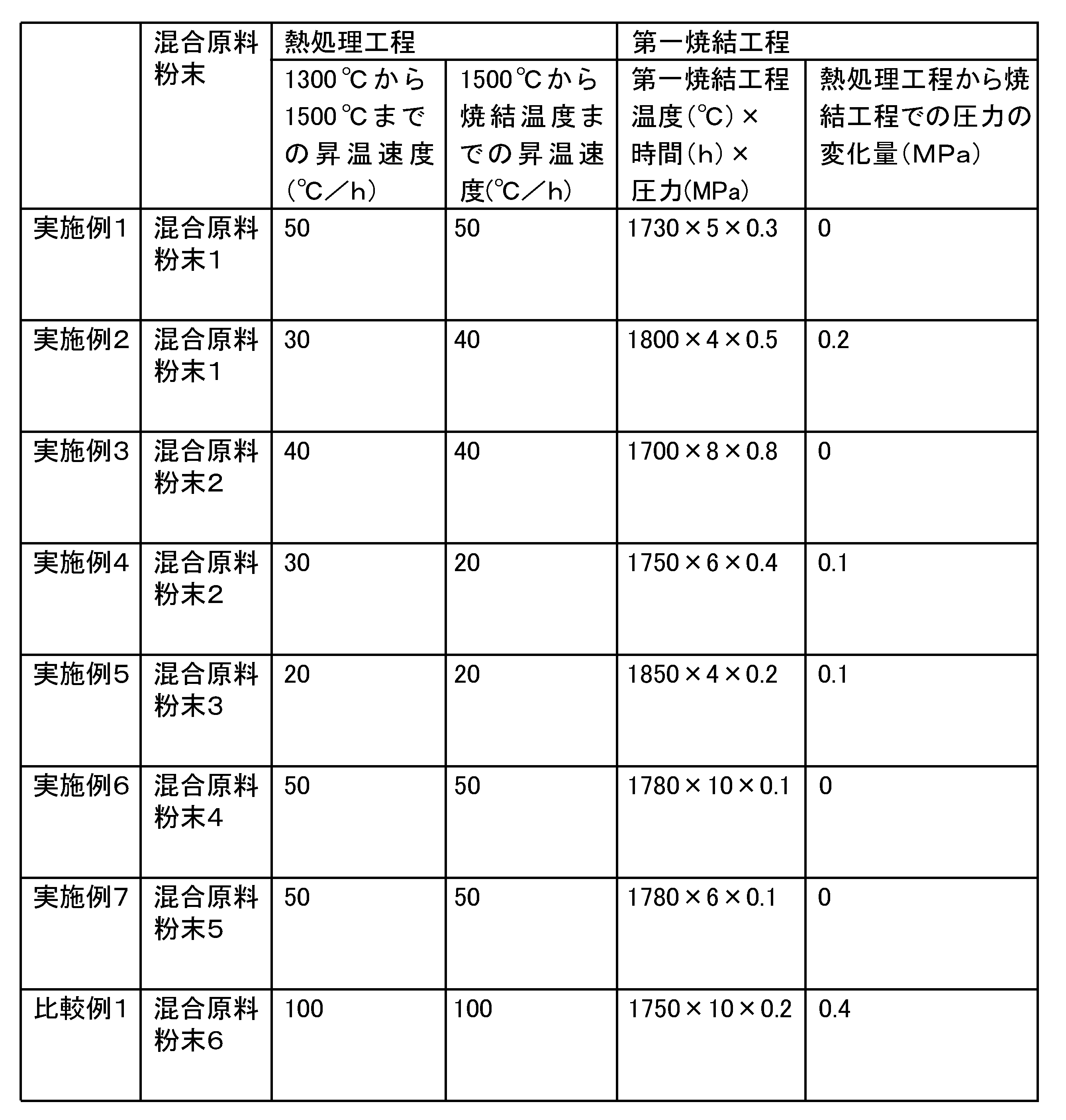
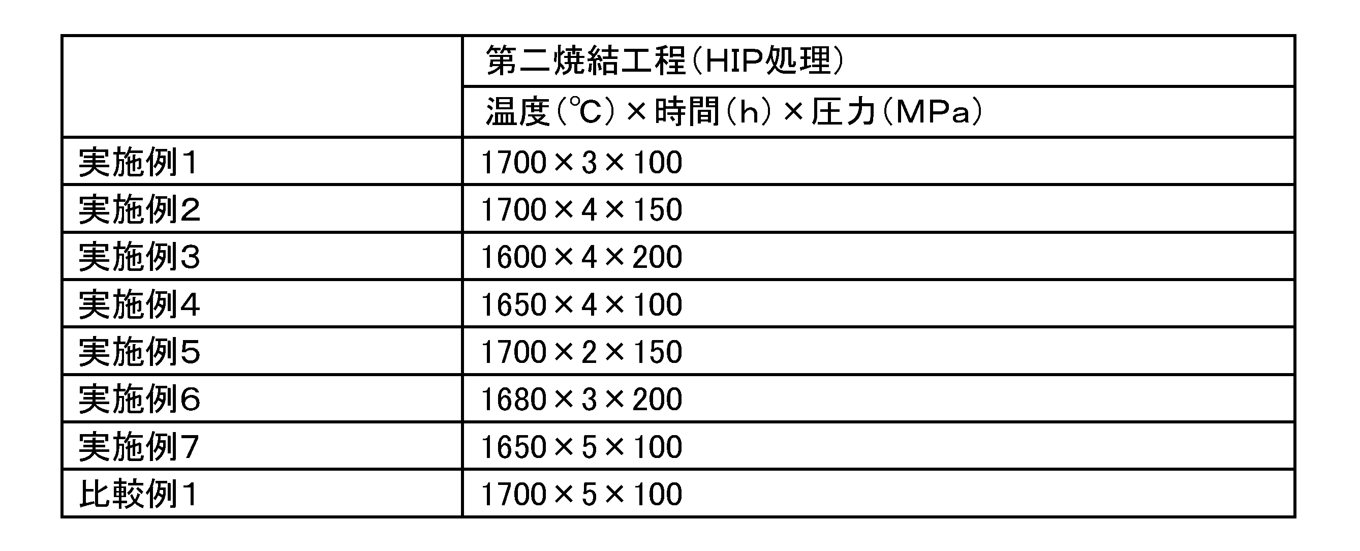
転位欠陥部の測定では、任意の断面をイオンミリング加工で表面粗さRaを1μm以下に加工した面を評価面とした。評価面をTEM観察した。TEMでは、評価面における50μm×50μmの領域を観察及び撮影した。また、一つの観察領域から1000μm離れた別の領域も観察及び撮影した。すなわち、合計2箇所の領域について、転位欠陥部を測定した。TEM写真の倍率は10000倍に設定し、明視野像および暗視野像を撮影した。暗視野像で白く見える領域を転位欠陥部とした。明視野像と暗視野像を対比することにより、一つの窒化珪素結晶粒子内の転位欠陥部の有無、占有面積率を求めた。なお、TEM写真の端部で見切れている窒化珪素結晶粒子(窒化珪素結晶粒子の輪郭がすべて写っていないもの)は、カウントから除外した。また、転位欠陥部の占有面積率は、暗視野像を画像処理ソフトにて2値化し、白い領域と黒い領域の面積比を求めることにより測定した。
また、転位欠陥部の核となっている元素を分析した。転位欠陥部はEDXを用いて分析した。これにより、転位欠陥部で、珪素、酸素および窒素以外の元素が1μm2以上の塊になっているか否か、10mol%以上に検出されるか否かを測定した。
3点曲げ強度はJIS-R-1601に準じて行った。破壊靱性はJIS-R-1607のIF法に準じて行い、新原の式を用いて求めた。
その結果を表4、表5に示した。

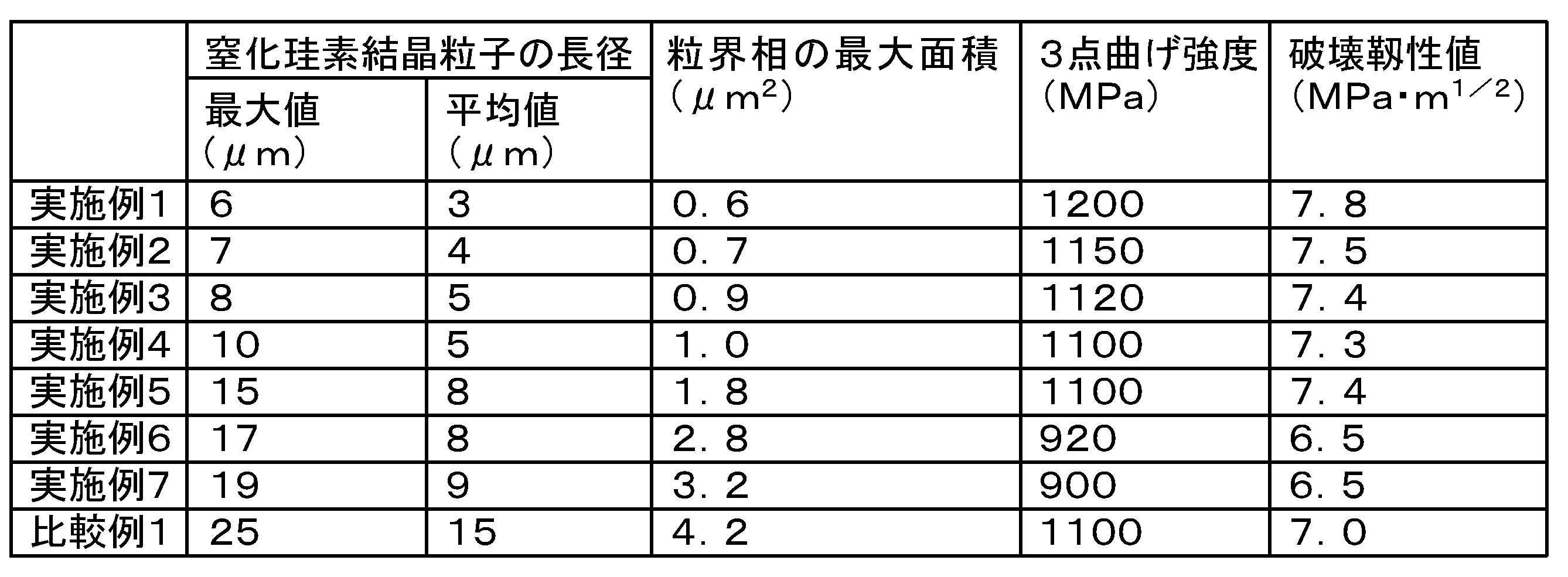
次に、ベアリングボールとしての耐久性試験を実施した。ベアリングボール16個を一組として、軌道輪(内輪及び外輪)に組み込み、軸受を作製した。各軸受の耐久性および耐電食特性を調べた。
耐久性試験は、軸受を「50rpmで1時間」→「1時間かけて50rpmから1000rpmに上げる」→「1000rpmで1時間」→「1時間かけて1000rpmを10000rpmに上げる」→「10000rpmで1時間」→「1時間かけて10000rpmを50rpmに下げる」を1セットとする条件で連続駆動させた。連続駆動が100時間の摺動音に対する、連続駆動が400時間又は800時間の摺動音の変化率を求めた。
摺動音の増加が10%以下を最良(◎)、10%を超えて20%未満を良好(○)、20%を超えたら不良(×)とした。この試験は、ベアリングボールの破損又は軌道輪の焼付けによる摺動状態の変化を調べたものである。なお、摺動音の測定は、JIS-B-1548に準じて行った。
また、耐電食特性は、800時間経過後の電食の有無で調べた。その結果を表6に示す。
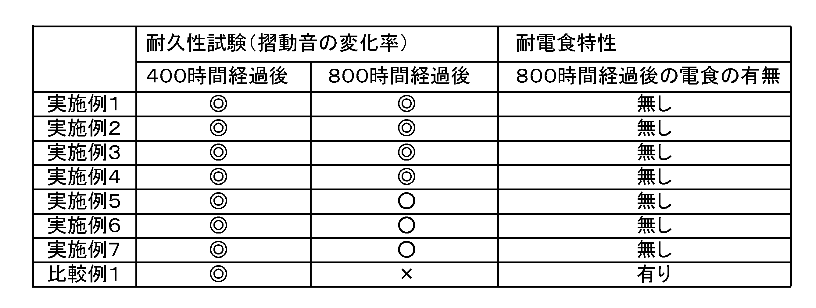
それに対し、比較例1は、耐久性試験は400時間程度では同等であったが、800時間を経過すると低下した。また、電食も発生した。転位欠陥部が所定量存在することにより、回転速度が変化する使用環境下では摺動特性に影響ができることが変わった。
2…転位欠陥部
3…窒化珪素結晶粒子の長径
10…軸受
11…ベアリングボール
12…内輪
13…外輪
14…回転軸
15…ロータ
16…ステータ
17…ケース
20…モータ
25…制御部
30…駆動装置
Claims (14)
- 窒化珪素結晶粒子及び粒界相を有する窒化珪素焼結体を備える摺動部材であって、
前記窒化珪素焼結体の任意の断面又は表面の観察領域50μm×50μmにおいて、全輪郭がみえる任意の50個の前記窒化珪素結晶粒子における、内部に転位欠陥部を有する前記窒化珪素結晶粒子の数の割合が、0%以上10%以下であることを特徴とする摺動部材。 - 前記割合が0%以上3%以下であることを特徴とする請求項1記載の摺動部材。
- 前記転位欠陥部において、珪素、酸素および窒素を除く成分が1μm2以上の塊になっていないことを特徴とする請求項1ないし請求項2のいずれか1項に記載の摺動部材。
- 前記転位欠陥部において、珪素、酸素および窒素を除く成分が10mol%以上検出されないことを特徴とする請求項1ないし請求項3のいずれか1項に記載の摺動部材。
- 前記転位欠陥部を有する前記窒化珪素結晶粒子の前記数に対する、前記転位欠陥部の占有面積率が5%以下である前記窒化珪素結晶粒子の数の割合が、70%以上であることを特徴とする請求項1ないし請求項4のいずれか1項に記載の摺動部材。
- 前記窒化珪素焼結体の任意の断面の観察領域300μm×300μmにおいて、前記窒化珪素結晶粒子の長径の最大値が25μm以下であることを特徴とする請求項1ないし請求項5のいずれか1項に記載の摺動部材。
- 前記窒化珪素焼結体の任意の断面の観察領域300μm×300μmにおいて、前記窒化珪素結晶粒子の長径の平均は1μm以上10μm以下の範囲内であることを特徴とする請求項1ないし請求項6のいずれか1項に記載の摺動部材。
- 前記窒化珪素焼結体の任意の断面の観察領域300μm×300μmにおいて、それぞれの前記粒界相の面積が9μm2以下であることを特徴とする請求項1ないし請求項7のいずれか1項に記載の摺動部材。
- 前記摺動部材は、ベアリングボールであることを特徴とする請求項1ないし請求項8のいずれか1項に記載の摺動部材。
- 請求項1ないし請求項9のいずれか1項に記載の摺動部材を具備したことを特徴とする軸受。
- 請求項10記載の軸受を具備したことを特徴とするモータ。
- 軸受の回転速度が50rpm以上となるように構成されたことを特徴とする請求項11記載のモータ。
- 軸受の回転速度が1000rpm以上変化するように構成されたことを特徴とする請求項11ないし請求項12のいずれか1項に記載のモータ。
- 請求項11ないし請求項12のいずれか1項に記載のモータと、
前記モータをインバータ駆動する制御部と、
を備えた駆動装置。
Priority Applications (6)
| Application Number | Priority Date | Filing Date | Title |
|---|---|---|---|
| CN202310221657.XA CN116161969B (zh) | 2018-12-11 | 2019-11-19 | 滑动构件及使用了其的轴承、发动机以及驱动装置 |
| JP2020559887A JP7402177B2 (ja) | 2018-12-11 | 2019-11-19 | 摺動部材、およびそれを用いた軸受、モータ、並びに駆動装置 |
| CN201980073611.XA CN112997017B (zh) | 2018-12-11 | 2019-11-19 | 滑动构件及使用了其的轴承、发动机以及驱动装置 |
| EP19895924.9A EP3896300B1 (en) | 2018-12-11 | 2019-11-19 | Bearing ball, bearing, motor and driving device using same |
| US17/236,580 US12371385B2 (en) | 2018-12-11 | 2021-04-21 | Sliding member, and bearing, motor, and drive device using the same |
| JP2023203807A JP7712996B6 (ja) | 2018-12-11 | 2023-12-01 | 窒化珪素焼結体製摺動部材の製造方法 |
Applications Claiming Priority (2)
| Application Number | Priority Date | Filing Date | Title |
|---|---|---|---|
| JP2018231856 | 2018-12-11 | ||
| JP2018-231856 | 2018-12-11 |
Related Child Applications (1)
| Application Number | Title | Priority Date | Filing Date |
|---|---|---|---|
| US17/236,580 Continuation US12371385B2 (en) | 2018-12-11 | 2021-04-21 | Sliding member, and bearing, motor, and drive device using the same |
Publications (1)
| Publication Number | Publication Date |
|---|---|
| WO2020121752A1 true WO2020121752A1 (ja) | 2020-06-18 |
Family
ID=71075628
Family Applications (1)
| Application Number | Title | Priority Date | Filing Date |
|---|---|---|---|
| PCT/JP2019/045268 Ceased WO2020121752A1 (ja) | 2018-12-11 | 2019-11-19 | 摺動部材、およびそれを用いた軸受、モータ、並びに駆動装置 |
Country Status (5)
| Country | Link |
|---|---|
| US (1) | US12371385B2 (ja) |
| EP (1) | EP3896300B1 (ja) |
| JP (2) | JP7402177B2 (ja) |
| CN (2) | CN112997017B (ja) |
| WO (1) | WO2020121752A1 (ja) |
Cited By (4)
| Publication number | Priority date | Publication date | Assignee | Title |
|---|---|---|---|---|
| WO2022210533A1 (ja) * | 2021-03-30 | 2022-10-06 | 株式会社 東芝 | 窒化珪素焼結体、耐摩耗性部材、及び窒化珪素焼結体の製造方法 |
| WO2022210539A1 (ja) * | 2021-03-30 | 2022-10-06 | 株式会社 東芝 | 窒化珪素焼結体、耐摩耗性部材、及び窒化珪素焼結体の製造方法 |
| WO2024070470A1 (ja) | 2022-09-27 | 2024-04-04 | 株式会社 東芝 | 窒化珪素焼結体、耐摩耗性部材、半導体装置用基板、及び窒化珪素焼結体の製造方法 |
| WO2024162443A1 (ja) * | 2023-02-01 | 2024-08-08 | Agc株式会社 | 窒化珪素質焼結体、ベアリング用転動体、窒化珪素質素球、及びベアリング |
Families Citing this family (3)
| Publication number | Priority date | Publication date | Assignee | Title |
|---|---|---|---|---|
| CN112292912B (zh) | 2018-08-29 | 2024-03-08 | 株式会社东芝 | 氮化硅基板及氮化硅电路基板 |
| JP7472408B2 (ja) * | 2022-03-16 | 2024-04-22 | 株式会社東芝 | 窒化珪素焼結体およびそれを用いた耐摩耗性部材 |
| CN117682868A (zh) * | 2023-11-29 | 2024-03-12 | 衡阳凯新特种材料科技有限公司 | 一种高性能大尺寸氮化硅陶瓷球及其制备方法和应用 |
Citations (5)
| Publication number | Priority date | Publication date | Assignee | Title |
|---|---|---|---|---|
| JP2000169239A (ja) * | 1998-12-01 | 2000-06-20 | Sumitomo Electric Ind Ltd | 高熱伝導性窒化ケイ素焼結体及びその製造方法 |
| JP2003063872A (ja) * | 2001-08-28 | 2003-03-05 | Toshiba Corp | 電子機器用耐摩耗性部材とその製造方法、およびそれを用いた電子機器用ベアリング |
| JP2011072113A (ja) * | 2009-09-25 | 2011-04-07 | Toshiba Corp | インバータ用転がり軸受及びそれを用いたインバータモータ |
| JP5380277B2 (ja) | 2007-03-15 | 2014-01-08 | 株式会社東芝 | 窒化珪素焼結体とそれを用いた摺動部材 |
| JP2016064971A (ja) * | 2014-09-25 | 2016-04-28 | 株式会社東芝 | 窒化珪素焼結体およびそれを用いた耐摩耗性部材 |
Family Cites Families (16)
| Publication number | Priority date | Publication date | Assignee | Title |
|---|---|---|---|---|
| TW209854B (ja) * | 1991-08-28 | 1993-07-21 | Hoechst Ceram Tec Ag | |
| JP5362758B2 (ja) | 2000-03-16 | 2013-12-11 | 株式会社東芝 | 耐摩耗性部材 |
| JP4744704B2 (ja) | 2000-03-16 | 2011-08-10 | 株式会社東芝 | 耐摩耗性部材の製造方法 |
| JP2002265276A (ja) * | 2001-03-07 | 2002-09-18 | Hitachi Metals Ltd | 窒化ケイ素粉末および窒化ケイ素焼結体 |
| JP2003034581A (ja) | 2001-07-24 | 2003-02-07 | Toshiba Corp | 窒化けい素製耐摩耗性部材およびその製造方法 |
| DE10136499A1 (de) * | 2001-07-27 | 2003-02-13 | Hans-Joachim Kleebe | Verfahren zur gezielten Veränderung des Gefüges von Si¶3¶N¶4¶-Keramiken im Frühstadium der Verdichtung (1400-1700 DEG C) |
| CN101100388B (zh) * | 2007-07-17 | 2010-06-09 | 清华大学 | 高热导率氮化硅陶瓷材料及其制备方法 |
| WO2009128386A1 (ja) | 2008-04-18 | 2009-10-22 | 株式会社東芝 | 耐摩耗性部材、耐摩耗性機器および耐摩耗性部材の製造方法 |
| JP5811391B2 (ja) | 2011-04-11 | 2015-11-11 | 日立金属株式会社 | 窒化珪素質セラミックス焼結体の製造方法および焼成容器 |
| WO2014069268A1 (ja) * | 2012-10-30 | 2014-05-08 | 株式会社東芝 | 窒化珪素焼結体およびそれを用いた耐磨耗性部材 |
| CN103011873A (zh) * | 2012-11-28 | 2013-04-03 | 大连大友高技术陶瓷有限公司 | 一种氮化硅增韧陶瓷球的制备方法 |
| DE102013202123C5 (de) * | 2013-02-08 | 2018-01-04 | Ks Gleitlager Gmbh | Gleitlagerverbundwerkstoff und hieraus hergestelltes Gleitlagerelement |
| US9663407B2 (en) * | 2013-06-13 | 2017-05-30 | Kabushiki Kaisha Toshiba | Silicon nitride wear resistant member and method for producing silicon nitride sintered compact |
| EP3248956B1 (en) * | 2015-01-23 | 2020-11-04 | Kabushiki Kaisha Toshiba | Silicon nitride substrate, and silicon nitride circuit board and semiconductor apparatus using the same |
| WO2016163263A1 (ja) | 2015-04-07 | 2016-10-13 | 株式会社東芝 | 窒化珪素焼結体およびそれを用いた高温耐久性部材 |
| CN112292912B (zh) * | 2018-08-29 | 2024-03-08 | 株式会社东芝 | 氮化硅基板及氮化硅电路基板 |
-
2019
- 2019-11-19 CN CN201980073611.XA patent/CN112997017B/zh active Active
- 2019-11-19 EP EP19895924.9A patent/EP3896300B1/en active Active
- 2019-11-19 JP JP2020559887A patent/JP7402177B2/ja active Active
- 2019-11-19 CN CN202310221657.XA patent/CN116161969B/zh active Active
- 2019-11-19 WO PCT/JP2019/045268 patent/WO2020121752A1/ja not_active Ceased
-
2021
- 2021-04-21 US US17/236,580 patent/US12371385B2/en active Active
-
2023
- 2023-12-01 JP JP2023203807A patent/JP7712996B6/ja active Active
Patent Citations (5)
| Publication number | Priority date | Publication date | Assignee | Title |
|---|---|---|---|---|
| JP2000169239A (ja) * | 1998-12-01 | 2000-06-20 | Sumitomo Electric Ind Ltd | 高熱伝導性窒化ケイ素焼結体及びその製造方法 |
| JP2003063872A (ja) * | 2001-08-28 | 2003-03-05 | Toshiba Corp | 電子機器用耐摩耗性部材とその製造方法、およびそれを用いた電子機器用ベアリング |
| JP5380277B2 (ja) | 2007-03-15 | 2014-01-08 | 株式会社東芝 | 窒化珪素焼結体とそれを用いた摺動部材 |
| JP2011072113A (ja) * | 2009-09-25 | 2011-04-07 | Toshiba Corp | インバータ用転がり軸受及びそれを用いたインバータモータ |
| JP2016064971A (ja) * | 2014-09-25 | 2016-04-28 | 株式会社東芝 | 窒化珪素焼結体およびそれを用いた耐摩耗性部材 |
Cited By (13)
| Publication number | Priority date | Publication date | Assignee | Title |
|---|---|---|---|---|
| JP7482316B2 (ja) | 2021-03-30 | 2024-05-13 | 株式会社東芝 | 窒化珪素焼結体、耐摩耗性部材、及び窒化珪素焼結体の製造方法 |
| WO2022210539A1 (ja) * | 2021-03-30 | 2022-10-06 | 株式会社 東芝 | 窒化珪素焼結体、耐摩耗性部材、及び窒化珪素焼結体の製造方法 |
| JPWO2022210539A1 (ja) * | 2021-03-30 | 2022-10-06 | ||
| JPWO2022210533A1 (ja) * | 2021-03-30 | 2022-10-06 | ||
| CN117043123A (zh) * | 2021-03-30 | 2023-11-10 | 株式会社东芝 | 氮化硅烧结体、耐磨性构件及氮化硅烧结体的制造方法 |
| WO2022210533A1 (ja) * | 2021-03-30 | 2022-10-06 | 株式会社 東芝 | 窒化珪素焼結体、耐摩耗性部材、及び窒化珪素焼結体の製造方法 |
| JP7581487B2 (ja) | 2021-03-30 | 2024-11-12 | 株式会社東芝 | 窒化珪素焼結体、耐摩耗性部材、及び窒化珪素焼結体の製造方法 |
| EP4317107A4 (en) * | 2021-03-30 | 2025-02-19 | Kabushiki Kaisha Toshiba | Silicon nitride sintered body, wear-resistant member, and method for manufacturing silicon nitride sintered body |
| EP4317106A4 (en) * | 2021-03-30 | 2025-02-19 | Kabushiki Kaisha Toshiba | SILICON NITRIDE SINTERED BODY, WEAR-RESISTANT ELEMENT AND METHOD FOR PRODUCING A SILICON NITRIDE SINTERED BODY |
| WO2024070470A1 (ja) | 2022-09-27 | 2024-04-04 | 株式会社 東芝 | 窒化珪素焼結体、耐摩耗性部材、半導体装置用基板、及び窒化珪素焼結体の製造方法 |
| WO2024162443A1 (ja) * | 2023-02-01 | 2024-08-08 | Agc株式会社 | 窒化珪素質焼結体、ベアリング用転動体、窒化珪素質素球、及びベアリング |
| JPWO2024162443A1 (ja) * | 2023-02-01 | 2024-08-08 | ||
| JP7778329B2 (ja) | 2023-02-01 | 2025-12-02 | Agc株式会社 | 窒化珪素質焼結体、ベアリング用転動体、窒化珪素質素球、及びベアリング |
Also Published As
| Publication number | Publication date |
|---|---|
| JP7712996B2 (ja) | 2025-07-24 |
| JP2024019273A (ja) | 2024-02-08 |
| CN112997017B (zh) | 2023-03-24 |
| EP3896300C0 (en) | 2025-12-17 |
| US12371385B2 (en) | 2025-07-29 |
| EP3896300B1 (en) | 2025-12-17 |
| US20210261467A1 (en) | 2021-08-26 |
| EP3896300A4 (en) | 2022-08-31 |
| CN112997017A (zh) | 2021-06-18 |
| CN116161969A (zh) | 2023-05-26 |
| CN116161969B (zh) | 2024-06-21 |
| EP3896300A1 (en) | 2021-10-20 |
| JP7402177B2 (ja) | 2023-12-20 |
| JP7712996B6 (ja) | 2025-08-27 |
| JPWO2020121752A1 (ja) | 2021-10-21 |
Similar Documents
| Publication | Publication Date | Title |
|---|---|---|
| JP7402177B2 (ja) | 摺動部材、およびそれを用いた軸受、モータ、並びに駆動装置 | |
| JP5380277B2 (ja) | 窒化珪素焼結体とそれを用いた摺動部材 | |
| JP5830439B2 (ja) | 転動体及びその製造方法 | |
| CN103764596B (zh) | 氮化硅烧结体及其制造方法、及使用其的耐磨部件和轴承 | |
| CN102138016B (zh) | 滚动轴承及其制造方法 | |
| CN104768900B (zh) | 氮化硅烧结体以及使用该氮化硅烧结体的滑动构件 | |
| JP2008285349A (ja) | 窒化珪素焼結体とそれを用いた摺動部材 | |
| JP7472408B2 (ja) | 窒化珪素焼結体およびそれを用いた耐摩耗性部材 | |
| JP5989602B2 (ja) | 窒化珪素質焼結体及びその製造方法、並びにベアリング用転動体 | |
| JP7482316B2 (ja) | 窒化珪素焼結体、耐摩耗性部材、及び窒化珪素焼結体の製造方法 | |
| JP7581487B2 (ja) | 窒化珪素焼結体、耐摩耗性部材、及び窒化珪素焼結体の製造方法 | |
| JP5988370B2 (ja) | セラミック転動体 | |
| WO2003084895A1 (fr) | Element anti-usure en nitrure de silicium et procede de fabrication correspondant | |
| JP2012163164A (ja) | モータ用転がり軸受 | |
| JP5295983B2 (ja) | 窒化けい素製耐摩耗性部材の製造方法 | |
| WO2025053251A1 (ja) | セラミックス焼結体、耐摩耗性部材、および、セラミックス焼結体の製造方法 | |
| WO2025041805A1 (ja) | 窒化珪素焼結体およびそれを用いた耐摩耗材部材 | |
| WO2025154683A1 (ja) | 窒化珪素焼結体およびそれを用いた耐摩耗性部材 | |
| WO2025159155A1 (ja) | 窒化珪素焼結体およびそれを用いた耐摩耗性部材 | |
| WO2014115785A1 (ja) | 転がり軸受 | |
| JP2015169283A (ja) | 転がり支持装置及びその製造方法 |
Legal Events
| Date | Code | Title | Description |
|---|---|---|---|
| 121 | Ep: the epo has been informed by wipo that ep was designated in this application |
Ref document number: 19895924 Country of ref document: EP Kind code of ref document: A1 |
|
| ENP | Entry into the national phase |
Ref document number: 2020559887 Country of ref document: JP Kind code of ref document: A |
|
| NENP | Non-entry into the national phase |
Ref country code: DE |
|
| ENP | Entry into the national phase |
Ref document number: 2019895924 Country of ref document: EP Effective date: 20210712 |
|
| WWG | Wipo information: grant in national office |
Ref document number: 2019895924 Country of ref document: EP |