WO2020121591A1 - Procédé de formage à la presse - Google Patents
Procédé de formage à la presse Download PDFInfo
- Publication number
- WO2020121591A1 WO2020121591A1 PCT/JP2019/030639 JP2019030639W WO2020121591A1 WO 2020121591 A1 WO2020121591 A1 WO 2020121591A1 JP 2019030639 W JP2019030639 W JP 2019030639W WO 2020121591 A1 WO2020121591 A1 WO 2020121591A1
- Authority
- WO
- WIPO (PCT)
- Prior art keywords
- press
- bead
- vertical wall
- top plate
- forming
- Prior art date
Links
Images


Classifications
-
- B—PERFORMING OPERATIONS; TRANSPORTING
- B21—MECHANICAL METAL-WORKING WITHOUT ESSENTIALLY REMOVING MATERIAL; PUNCHING METAL
- B21D—WORKING OR PROCESSING OF SHEET METAL OR METAL TUBES, RODS OR PROFILES WITHOUT ESSENTIALLY REMOVING MATERIAL; PUNCHING METAL
- B21D22/00—Shaping without cutting, by stamping, spinning, or deep-drawing
- B21D22/20—Deep-drawing
- B21D22/26—Deep-drawing for making peculiarly, e.g. irregularly, shaped articles
-
- B—PERFORMING OPERATIONS; TRANSPORTING
- B21—MECHANICAL METAL-WORKING WITHOUT ESSENTIALLY REMOVING MATERIAL; PUNCHING METAL
- B21D—WORKING OR PROCESSING OF SHEET METAL OR METAL TUBES, RODS OR PROFILES WITHOUT ESSENTIALLY REMOVING MATERIAL; PUNCHING METAL
- B21D22/00—Shaping without cutting, by stamping, spinning, or deep-drawing
- B21D22/20—Deep-drawing
- B21D22/22—Deep-drawing with devices for holding the edge of the blanks
-
- B—PERFORMING OPERATIONS; TRANSPORTING
- B21—MECHANICAL METAL-WORKING WITHOUT ESSENTIALLY REMOVING MATERIAL; PUNCHING METAL
- B21D—WORKING OR PROCESSING OF SHEET METAL OR METAL TUBES, RODS OR PROFILES WITHOUT ESSENTIALLY REMOVING MATERIAL; PUNCHING METAL
- B21D24/00—Special deep-drawing arrangements in, or in connection with, presses
- B21D24/04—Blank holders; Mounting means therefor
-
- B—PERFORMING OPERATIONS; TRANSPORTING
- B21—MECHANICAL METAL-WORKING WITHOUT ESSENTIALLY REMOVING MATERIAL; PUNCHING METAL
- B21D—WORKING OR PROCESSING OF SHEET METAL OR METAL TUBES, RODS OR PROFILES WITHOUT ESSENTIALLY REMOVING MATERIAL; PUNCHING METAL
- B21D53/00—Making other particular articles
- B21D53/88—Making other particular articles other parts for vehicles, e.g. cowlings, mudguards
Definitions
- the present invention relates to a press forming method, and in particular, has a top plate portion, a side wall portion, and a flange portion, and is along a longitudinal direction in a side view.
- the present invention relates to a press molding method for molding a press molded product that is curved in a convex shape and a concave shape in the height direction.
- ⁇ Press molding is a method of transferring the shape of the mold by pressing metal material such as steel sheet with a die of press forming to perform processing.
- metal material such as steel sheet
- many automotive parts are made by press molding.
- high-strength steel sheet high-tension steel sheet
- the tendency to use is becoming stronger.
- the ductility (elongation) tends to become poor.
- forming defects such as fracture and wrinkles often occur, which is a problem.
- Patent Document 1 in press molding of an L-shaped part that is curved in a top view, the molding force for molding a flange and a vertical wall is used to slide on a bottom surface of a material punch. ) And forming, thereby avoiding wrinkles on the bottom of the punch and cracks on the flange.
- Patent Document 2 in the press forming of a curved press part having a hat-shaped cross section that is curved in the longitudinal direction, a bending part is formed at the widthwise end of a blank material by preforming.
- this technique by providing a bent portion to the widthwise end portion of the blank material in preforming, the rigidity (stiffness) of the widthwise end portion is increased, and the counter force against the force contracting in the longitudinal direction is large. Therefore, it is said that it is possible to suppress the occurrence of wrinkles in the flange portion even if the force of contracting in the longitudinal direction due to the excess metal due to the curved shape acts.
- a blank material has a curvature when viewed in a plan view, and has a flange surface below a vertical wall surface when viewed in side view, which is pressed in one step.
- a technique is disclosed in which wrinkles are prevented from occurring in the material forming portion by providing a convex bead on the vertical wall surface and a concave bead on the flange surface immediately below.
- Patent Document 4 when a press part having a curved portion that is curved in a plan view and a hat-shaped cross-sectional shape is pressed in one step by a free bending method (bend forming), the inner peripheral side of the curved portion is disclosed. According to the technique, by forming a bead having a convex shape in the vicinity (outer side) of a portion formed on the flange on the inner peripheral side of the curved portion in the blank, the rotation of the material in the free bending method is promoted, and It is said that the amount of material that flows into the flange portion increases, and cracks at the flange portion can be prevented.
- Patent Document 5 a press-formed component having a top plate portion, a vertical wall portion, and a flange portion is preformed into a bead shape at a position of a material corresponding to the vicinity of a position where cracks or flange wrinkles occur, and thereafter, A technique of press-molding from a material in which a bead shape is preformed is disclosed. According to the technique, when a press-molded part is molded, the bead shape located in the vicinity is crushed in the vicinity of a position where cracks or flange wrinkles occur, so that the material is supplied from there, so that the material is excessively extended. It is said that it is possible to prevent the occurrence of cracks and the occurrence of flange wrinkles due to too much inflow of material from the flange portion.
- both of the techniques disclosed in Patent Document 3 and Patent Document 4 perform press working in one step, and there is a problem that the bead added to prevent wrinkle generation or cracking remains as it is. It was Further, in the technique disclosed in Patent Document 5, the bead preformed on the material is crushed to reduce deformation in the direction orthogonal to the bead. However, the direction of the bead to be preformed and the bead There is no disclosure regarding the flow direction of the material when it is crushed, and it may not be possible to effectively prevent cracks and wrinkles.
- the present invention has been made in view of the above problems, and an object thereof is to have a top plate portion, a vertical wall portion, and a flange portion, and have a convex shape and a concave shape in the height direction along the longitudinal direction in a side view. It is an object of the present invention to provide a press-molding method capable of obtaining a good press-molded product without causing cracks or wrinkles when press-molding a press-molded product that is curved in a vertical direction.
- the press molding method according to the present invention includes a top plate portion, a vertical wall portion continuous from the top plate portion via a top plate side ridge line, and a flange portion continuous from the vertical wall portion.
- a press-formed product having a convex curved portion (curved portion) curved in a height direction along a longitudinal direction in a side view and a concave curved portion curved in a concave shape.
- the part is inclined so that the end located on the convex curved part side of the major axis of the bead part is away from the base line and the end located on the opposite side approaches the base line, and the part is formed sandwiching the concave curved part.
- the bead portion is characterized in that the end portion located on the concave curved portion side of the major axis of the bead portion approaches the base line and the end portion located on the opposite side is inclined away from the base line. It is a thing.
- an angle ⁇ between a major axis of the bead portion and the base line is 5° or more and 60° or less. It is characterized by that.
- the angle ⁇ formed by the major axis of the bead portion and the base line is defined by the molding direction of the press molded product in the main molding step and the top plate side ridge line portion.
- the vertical wall portion of the portion adjacent to the convex curved portion and the concave curved portion is subjected to pseudo-shear deformation to be molded, and thereby the compressive deformation of the convex curved portion and the concave curved portion.
- pseudo-shear deformation to be molded, and thereby the compressive deformation of the convex curved portion and the concave curved portion.
- FIG. 1 is a diagram illustrating a molding process in a press molding method according to an embodiment of the present invention ((a) blank, (b) intermediate molded product, (c) press molded product).
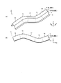
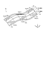
- FIG. 2 is a diagram for explaining a press-formed product which is a molding target in the present invention ((a) perspective view, (b) side view).
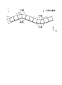
- FIG. 3 is a diagram for explaining the movement of a material when a press-formed product to be formed by the present invention is formed by a conventional press-forming method and a portion where tensile deformation and compression deformation occur in the press-formed product.
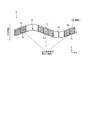
- FIG. 4 is a diagram illustrating a press-formed product in which a vertical wall portion is formed by inducing shear deformation in the background of the present invention.
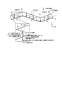
- FIG. 5 is a diagram for explaining the movement of the material when a press-formed product is formed by the press-forming method according to the embodiment of the present invention.
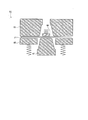
- FIG. 6 shows the movement of the material due to the crushing of the bead portion formed in the intermediate molded product and the movement of the material due to bending at the top plate side ridge line portion in the press molding method according to the embodiment of the present invention.
- FIG. 6 is a diagram for explaining each movement (pseudo-shear deformation) of the material in the main forming step.
- FIG. 7: is a figure which shows the other aspect of the intermediate molded product shape
- FIG. 8 is a figure which shows the other aspect of the intermediate molded product shape
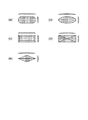
- FIG. 9 is a diagram showing a specific example of the shape of the bead portion formed in the intermediate molded product in the preforming step in the press molding method according to the present invention.
- FIG. 10 is a diagram for explaining foam forming (crash forming) applied in the press forming method according to the present invention.
- FIG. 11 is a figure explaining the foam molding using the pad (pad) applied in the press molding method which concerns on this invention.
- FIG. 12 is a diagram for explaining draw drawing applied in the press forming method according to the present invention.
- FIG. 13 is a diagram illustrating draw molding using a pad applied in the press molding method according to the present invention.
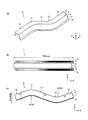
- FIG. 14 is a diagram showing a press-molded product which is a molding target in the examples ((a) perspective view, (b) top view, (c) side view).
- FIG. 15 is a cross-sectional view of a press-formed product which is a molding target in the examples.
- the X axis, the Y axis, and the Z axis in the drawings indicate the longitudinal direction, the width direction, and the height direction of the press-formed product, respectively. Further, in the present embodiment, the height direction of the press-formed product is supposed to coincide with the forming direction of the press-formed product.
- the press-formed product 1 targeted by the present invention includes a top plate portion 3, and a vertical wall portion 7 continuous from the top plate portion 3 via a top plate side ridge line portion 5, It has a hat-shaped cross section having a vertical wall portion 7 and a continuous flange portion 9, and has a convex curved portion 11 that is convexly curved in the height direction along the longitudinal direction in a side view and a concave curved portion 13 that is concavely curved. And have.
- a straight line portion 15 and a straight line portion 17 are provided on both sides in the longitudinal direction of the convex curved portion 11, and a straight line portion 17 and a straight line portion 19 are provided on both sides of the concave curved portion 13 in the longitudinal direction.
- the center of the arc curved in a convex shape in the side view is on the flange portion 9 side
- the center of the arc curved in the concave shape in the side view is on the top plate portion 3 side. It is in.
- the press-molded product to be molded in the present invention may be one that bends in the height direction along the longitudinal direction.
- the molding direction is the Z direction
- the press-molded product is Curved in the ZX plane including stroke axis, that is, curved in side view.
- Fig. 3 shows the movement of the material during molding when the press-formed product 1 is viewed from the side.
- the blank metal plate
- the blank is bent at the top plate side ridge line portion 5 between the top plate portion 3 and the vertical wall portion 7, and is orthogonal to the top plate side ridge line portion 5 (see FIG. Material moves in the direction of the arrow inside). Then, a line length difference occurs in the longitudinal direction between the flange portion 9 and the top plate portion 3.
- the top plate portion 3 and the flange portion 9 are pulled. It is considered important to reduce the line length difference in the longitudinal direction between the top plate portion 3 and the flange portion 9 by changing the movement of the material during the forming process so as not to cause the deformation or the compression deformation.
- the present inventor diligently studied a concrete method for realizing this.
- the vertical wall portions 7a, 7b, 7c of the straight line portions 15, 17, 19 are formed.
- the material should be subjected to shear deformation so as to be molded.
- the top plate portion 3 and the flange portion 9 are strongly sandwiched and the shear force is applied to the vertical wall portions 7a, 7b, 7c.
- the step of forming the press-formed product 1 is divided into two steps.
- a shape for controlling the movement of the material that undergoes shear deformation in the forming process of the vertical wall portions 7a, 7b, 7c is formed.
- the second step it was conceived that the vertical wall portions 7a, 7b, 7 should be formed by inducing a pseudo-shear deformation in the portion provided with the shape for controlling the movement of the material.
- the present invention has been made based on the above studies, and the press molding method according to the embodiment of the present invention will be described below.
- the press molding method according to the present embodiment is for molding the press molded product 1 shown in FIG. 2, and as shown in FIG. 1, a preforming step of preforming the blank 21 into an intermediate molded product 31.
- the main molding step of molding the intermediate molded product 31 into the press molded product 1 is provided. The above steps will be described below.
- the preforming step is a step of preforming the blank 21 into an intermediate molded product 31.
- the intermediate molded product 31 includes the convex curved portion 11 of the press molded product 1.
- Vertical wall equivalent surface portions 33a and 33b which are portions corresponding to the vertical wall portions 7a and 7b (see FIG. 1C) in the straight portions 15 and 17 on both sides in the longitudinal direction with the concave curved portion 13 interposed therebetween.
- Corresponding to the vertical wall-corresponding surface portions 33b and 33c which are the portions corresponding to the vertical wall portions 7b and 7c (see FIG. 1C) in the straight line portions 17 and 19 on both sides in the longitudinal direction, and to the top plate side ridge line portion 5.
- the bead portion 37 (37a, 37b, 37c) that is inclined with respect to the base line 35 is formed.
- the bead portions 37a and 37b formed on the vertical wall-corresponding surface portions 33a and 33b on both sides in the longitudinal direction with the convex curved portion 11 interposed therebetween are located on the major curved convex portion 11 side of the bead portions 37a and 37b.
- the end portions 37a2 and 37b1 are separated from the base line 35, and the end portions 37a1 and 37b2 located on the opposite side are inclined so as to approach the base line 35.
- the bead portions 37b and 37c formed on the vertical wall-corresponding surface portions 33b and 33c on both sides in the longitudinal direction with the concave curved portion 13 sandwiched therebetween are ends located on the major curved concave curved portion 13 side of the bead portions 37b and 37c.
- the portions 37b2 and 37c1 approach the base line 35, and the end portions 37b1 and 37c2 located on the opposite side are inclined so as to move away from the base line 35.
- the acute angle side of the angle formed by the major axis of the bead portion 37 and the base line 35 in the vertical wall equivalent surface portion 33 where the bead portion 37 is formed. It is desirable that the angle ⁇ is in the range of 5° to 60°. Further, as shown in FIG. 5(b), when an angle on the acute angle side of the angle formed by the molding direction of the press-formed product 1 and the top plate side ridge line portion 5 in the main molding step described later is ⁇ 1 , the angle ⁇ formed by the major axis of the bead portion 37 and the base line 35 preferably satisfies the relationship of ⁇ 2 ( 90° ⁇ 1 ). In addition, the suitable range of the angle ⁇ of the bead portion 37 will be demonstrated in Examples described later.
- the intermediate molded article 31 may be molded by using a mold for molding the press molded article 1, whereby the bead portion 37 provided in the preforming step is crushed to have a flat shape.
- the direction orthogonal to the bead portion of the bead portion 37 and the main direction is the same (see FIG. 5B)
- the bead portion 37 when the bead portion 37 is crushed in the main forming process, the bead portion 37 extends in the bead orthogonal direction most efficiently, and the vertical wall equivalent surface portion
- the pseudo shear deformation can be effectively induced in 33.
- FIG. 6 shows the movement of the material by the press molding method according to the present invention.
- the vertical wall portion 7 moves the material in a direction orthogonal to the top plate side ridge line portion 5.
- the press molding method according to the present invention when the intermediate molded product 31 molded in the preforming step is molded into the press molded product 1, the bead portion 37 formed on the vertical wall equivalent surface portion 33 is crushed. It becomes a stretched deformation. At this time, the material of the bead portion 37 moves in a direction orthogonal to the major axis of the bead portion 37 (bead orthogonal direction). As a result, as shown in FIG. 6, the press forming direction component of the movement of the material due to the bead portion 37 being crushed and the press forming direction component of the movement of the material due to bending in the ridge line orthogonal direction at the top plate side ridge line portion 5.
- the tensile deformation of the top plate portion 3 of the convex curved portion 11 is also relaxed and formed. It is possible to suppress cracks in the top plate portion 3 of the curved section 11. Further, since the press-formed product 1 is formed by relaxing the tensile deformation of the flange portion 9 of the concave curved portion 13, the compressive deformation of the top plate portion 3 of the concave curved portion 13 is mitigated, and the flange of the concave curved portion 13 is reduced. Wrinkles in the portion 9 can also be suppressed.
- Patent Document 5 pre-forms a convex or concave bead portion at a portion corresponding to a vertical wall portion of a blank, and crushes the bead portion to obtain a target press-formed product.
- it is similar to the press molding method according to the present invention at first glance.
- a bead portion is directly preformed on a portion where a crack is generated in the first step, that is, a vertical wall portion which is continuous with a flange portion where a top plate portion and wrinkles are generated, and then continued.
- the bead portion is crushed to promote the material inflow to the portion where cracks occur and the material outflow from the portion where wrinkles occur.
- a bead portion is formed on a vertical wall portion that is continuous with the top plate portion and the flange portion without cracks and wrinkles, and the bead portion is formed in the main molding step which is the second step.
- the bead portion 37 formed in the preforming step may be one that is inclined with respect to the base line 35 as described above, but the angle ⁇ of the bead portion 37 may be 5° or more and 60° or less. preferable.
- the movement of the material in the direction is synergistic, and further, the movement of the material in the direction orthogonal to the press forming due to the bead portion 37 being crushed and the material in the direction orthogonal to the press forming due to being bent in the direction orthogonal to the ridge line at the top plate side ridge line portion 5 are offset, and the amount of shear deformation of the surface portion corresponding to the vertical wall portion can be increased, so that compressive deformation of the flange portion 9 of the convex curved portion 11 and tensile deformation of the flange portion 9 of the concave curved portion 13 can be prevented. It can be further mitigated.
- the molding direction and the direction in which the bead portion is crushed and extended coincide with each other.
- the part 37 can be extended most efficiently in the bead orthogonal direction.
- the material can be moved in a desired direction during molding in the main molding process. It is possible to deal with various forming conditions and material strength of blanks used for forming.
- the present invention is not limited to the one in which the intermediate molded product 31 having a shape in which only the bead portion 37 is provided to the flat plate-shaped blank is formed in the preforming process as shown in FIG. A bead portion may be added to a shape close to the press-formed product 1 to be formed.
- a top plate portion 43 curved in a convex shape and a concave shape in the height direction, a vertical wall equivalent surface portion 47 continuous from the top plate portion 43 via a top plate side ridge line portion 45,
- the intermediate molded product 41 having the flange portion 49 and the bead portion 51 formed on the surface portion 47 corresponding to the vertical wall may be molded.
- FIG. 1 A cross-sectional view of the intermediate molded product 41 and the press molded product 1 is shown in FIG.
- the angle ⁇ of the vertical wall equivalent surface portion 47 in the intermediate molded product 41 is smaller than the angle ⁇ 0 of the vertical wall portion 7 of the press molded product 1, and the vertical wall height h of the intermediate molded product 41 is set to the vertical wall height of the press molded product 1.
- the vertical wall equivalent surface portion 47 can be molded into the vertical wall portion 7 while crushing the bead portion 51 in the main molding process.
- top plate side ridge line portion 45 in the intermediate molded product 41 has a bent shape that connects the top plate portion 43 and the vertical wall equivalent surface portion 47 (see FIG. 8 ), the top plate side ridge line portion 45 and the vertical plate side ridge line portion 45 The bead portion 51 on the wall equivalent surface portion 47 is not located on the same plane.
- the bead portion 37 (FIG. 1(b)) or the bead portion 51 (FIG. 7) has an oval shape in plan view (FIG. 9(a)), but the present invention has this shape.
- the shape is not limited to this, and the shape shown in FIGS. 9B to 9E may be used.
- the height and number of the bead portions formed on the intermediate molded product in the preforming step are not limited, but the height of the bead portions is increased, and by forming a larger number of the bead portions, the vertical portion where the bead portions are formed is formed.
- the cross-section line length of the wall-equivalent surface portion becomes large, the movement of the material when the bead portion is flatly formed in the main forming step can be further increased, and a better effect of reducing cracks and wrinkles can be obtained.
- the bead portion may have a convex or concave cross section orthogonal to the long axis.
- the major axis of each of the convex bead portion and the concave bead portion may be alternately formed.
- it is preferable that the major axes of the bead portions are parallel to each other.
- the position where the bead portion is formed is, like the straight line portions 15, 17, and 19 shown in FIG. 1, a portion adjacent to the convex curved portion 11 or the concave curved portion 13 where cracks or wrinkles occur, or the degree of bending is loose. It is desirable to be a part.
- the bead portion formed in the intermediate molded product may have its end portion slightly inserted into the vertical wall equivalent surface portion of the convex curved portion or the vertical wall equivalent surface portion of the concave curved portion.
- both foam forming and draw forming can be applied.
- FIG. 10 shows an example of a cross-sectional view of the mold 61 and the blank 21 in forming a foam.
- the foam molding is a method of molding by sandwiching the blank 21 with an upper die 63 and a lower punch 65, and is applicable to both the preforming step and the main forming step according to the present invention.
- a die 71 having a pad 77 as shown in FIG. 11 is used, and a die 77 is used while pressing a surface portion corresponding to a top plate portion of the blank 21 by the pad 77 which is paired with the punch bottom portion 75a of the punch 75. It is also possible to form the foam with 73 and the punch 75.
- FIG. 12 shows a cross-sectional view of the die 81 and the blank 21 in draw forming.
- the draw forming is a method of forming by lowering (relatively moving) the die 83 and the blank holder 85 toward the punch 87 side while holding the blank 21 with the die 83 and the blank holder 85, and the preforming step according to the present invention. It can be applied to both of the main molding process. Further, according to the present invention, a die 91 having a pad 99 as shown in FIG. 13 is used, and the surface of the blank 21 corresponding to the top plate portion is pressed by the pad 99 that is paired with the punch bottom portion 97a of the punch 97. Draw forming may be performed while holding the blank 21 with the die 93 and the blank holder 95.
- the press forming method according to the present invention is not limited to a steel plate, and may be a metal plate.
- a steel plate for example, coated steel sheet, aluminum sheet, aluminum alloy sheet, etc.
- a press-formed product 1 having a hat-shaped cross section having a convex curved portion 11 that is convexly curved in the height direction and a concave curved portion 13 that is concavely curved. It was supposed to be press molded.
- both the curvature radius of the convex curved portion 11 and the curvature radius of the concave curved portion 13 in the Z-axis direction are R150.
- a 1180 MPa grade steel sheet having a plate thickness of 1.2 mm was used as the material.
- an intermediate formed product was formed by the preforming process according to the present invention, and then the intermediate formed product was formed into a press-formed product by the main forming process, which was taken as an example of the present invention.
- the press forming method in the preforming step was foam forming (see FIG. 10) or draw forming (see FIG. 12), and the press forming method in the main forming step was also foam forming or draw forming.
- the case where the pad was used for the forming was also examined (see FIGS. 11 and 13).
- the blank holder load was 50 tonf, and when the pad was used, the pad load was 10 tonf.
- the preforming step includes a case where an intermediate molded product 31 having a shape in which only a bead portion 37 is applied to a flat plate-shaped blank as shown in FIG. 1B is formed, and a top plate portion as shown in FIGS. 7 and 8.
- the angle ⁇ formed by 51 and the base line corresponding to the top plate side ridge line portion 45 was 5 conditions of 3°, 5°, 20°, 60° and 70°.
- the press-molded product 1 is molded in one step without forming a bead portion in a conventional example, and the press-molded product 1 is molded in two steps of a pre-molding process and a main molding process as in the case of the present invention. Therefore, a comparative example was one in which the angle ⁇ (see FIG. 1B) of the bead portion formed in the intermediate molded product in the preforming step was outside the preferred range of the present invention.
- the formability was evaluated by the presence or absence of cracks and wrinkles in the flange portion 9 and the top plate portion 3 of the press-formed product 1.
- the evaluation of cracks the presence or absence of cracks in the top plate portion 3 of the convex curved portion 11 and the flange portion 9 of the concave curved portion 13 is observed. If cracks are present, x is determined. ), it was evaluated as ⁇ , and when there was no crack or constriction, it was evaluated as ⁇ .
- the wrinkle evaluation the presence or absence of wrinkles in the flange portion 9 of the convex curved portion 11 and the top plate portion 3 of the concave curved portion 13 is observed. When there is a noticeable wrinkle, x, when there is a small wrinkle, wrinkle is observed. When there is no such item, it is marked as ⁇ . Table 1 shows the evaluation results of molding conditions and moldability.
- [A] to [E] in the leftmost column of Table 1 show a group of invention examples and comparative examples in which the pressing method and the presence or absence of the pad in the preforming step and the main forming step are the same conditions.
- Group A is for forming a flat intermediate product 31 in the preforming step, forming the preforming step as foam, and forming the main forming step as foam, without using a pad in both the preforming step and the main forming step. (Invention Examples 1 to 5)
- the top plate portion 3 of the convex curved portion 11 and the flange portion 9 of the concave curved portion 13 are constricted due to the reduction of the plate thickness.
- the top plate portion 3 of the convex curved portion 11 and the flange portion 9 of the concave curved portion 13 were constricted due to the reduction of the plate thickness.
- Group B is to form a flat intermediate product 31 in the preforming step, form forming the preforming step, draw forming the main forming step, and use no pad in both the preforming step and the main forming step.
- the flat intermediate product 31 is formed in the preforming step, the preforming step is form forming, the main forming step is form forming, the preforming step is no pad, and the main forming step is with pad. (Examples 21 to 25 of the invention).
- the top plate portion 3 of the convex curved portion 11 is constricted due to the reduction of the plate thickness, and the flange of the concave curved portion 13 is formed.
- the part 9 was cracked.
- the top plate portion 3 of the convex curved portion 11 and the flange portion 9 of the concave curved portion 13 were constricted.
- Group D is to form a flat intermediate product 31 in the preforming step, the preforming step is foam forming, the main forming step is draw forming, the preforming step is no pad, and the main forming step is with pad. (Invention example 31 to invention example 35).
- Group E is for forming the intermediate molded product 41 in which the angle ⁇ of the vertical wall equivalent surface portion 47 is 30° in the preforming step, the preforming step is without a pad, and the main forming step is with a pad ( Invention Example 41 to Invention Example 45).
- the top plate portion, the vertical wall portion and the flange portion when press-molding a press-formed product curved in a convex shape and a concave shape in the height direction along the longitudinal direction in a side view, cracks and It is possible to provide a press molding method capable of obtaining a good press molded product without causing wrinkles.
- Top plate part 5 Top plate side ridge line part 7, 7a, 7b, 7c Vertical wall part 9 Flange part 11 Convex curved part 13 Concave curved part 15, 17, 19 Straight part 21 Blank 31 Intermediate molded product 33 , 33a, 33b, 33c Vertical wall equivalent surface portion 35 Base line 37, 37a, 37b, 37c Bead portion 37a1, 37a2, 37b1, 37b2, 37c1, 37c2 End portion 41 Intermediate molded product 43
- Top plate portion 45 Top plate side ridge portion 47, 47a, 47b, 47c Vertical wall equivalent surface portion 49 Flange portion 51, 51a, 51b, 51c Bead portion 61 Mold (form molding) 63 die 65 punch 71 mold (form molding) 73 Die 75 Punch 75a Punch Bottom 77 Pad 81 Mold (Draw Molding) 83 Die 85 Blank Holder 87 Punch 91 Mold (Draw Molding) 93 die 95 blank holder 97 punch 97a punch bottom 99 pad
Abstract
La présente invention concerne un procédé de formage à la presse qui est un procédé permettant de former un produit formé à la presse (1) ayant une section plaque supérieure (3), des sections parois verticales (7), des sections brides (9), et un site incurvé saillant (11) incurvé de manière saillante et un site incurvé évidé (13) incurvé de manière évidée dans la direction de la hauteur. Le procédé comprend : une étape de préformage pour former un produit formé intermédiaire (31) ayant des parties nervures (37) formées dans une section surface (33) correspondant à une paroi verticale, correspondant aux sections parois verticales (7) sur les deux côtés dans la direction longitudinale de chacun du site incurvé saillant (11) et du site incurvé évidé (13) ; et une étape de formage principale pour former le produit formé à la presse (1) par écrasement des parties nervures (37) du produit formé intermédiaire (31) et induisant ainsi une pseudo-déformation de cisaillement dans la section surface (33) correspondant à une paroi verticale. Lors de l'étape de préformage, les parties nervures (37) sont inclinées de telle sorte qu'une section extrémité de chaque partie nervure (37) sur le côté site incurvé saillant (11) est disposée à distance d'une ligne de base (35) correspondant à une section ligne de crête côté plaque supérieure (5) entre la section plaque supérieure (3) et la section paroi verticale (7), et de telle sorte qu'une section extrémité de la partie nervure (37) sur le côté opposé est plus proche de la ligne de base (35).
Priority Applications (5)
| Application Number | Priority Date | Filing Date | Title |
|---|---|---|---|
| US17/299,077 US20220055085A1 (en) | 2018-12-12 | 2019-08-05 | Press forming method |
| KR1020217017782A KR102450454B1 (ko) | 2018-12-12 | 2019-08-05 | 프레스 성형 방법 |
| MX2021007007A MX2021007007A (es) | 2018-12-12 | 2019-08-05 | Metodo de formacion en prensa. |
| CN201980081855.2A CN113226584B (zh) | 2018-12-12 | 2019-08-05 | 冲压成形方法 |
| EP19897191.3A EP3895824B1 (fr) | 2018-12-12 | 2019-08-05 | Procédé de formage à la presse |
Applications Claiming Priority (2)
| Application Number | Priority Date | Filing Date | Title |
|---|---|---|---|
| JP2018-232199 | 2018-12-12 | ||
| JP2018232199A JP6677289B1 (ja) | 2018-12-12 | 2018-12-12 | プレス成形方法 |
Publications (1)
| Publication Number | Publication Date |
|---|---|
| WO2020121591A1 true WO2020121591A1 (fr) | 2020-06-18 |
Family
ID=70057902
Family Applications (1)
| Application Number | Title | Priority Date | Filing Date |
|---|---|---|---|
| PCT/JP2019/030639 WO2020121591A1 (fr) | 2018-12-12 | 2019-08-05 | Procédé de formage à la presse |
Country Status (7)
| Country | Link |
|---|---|
| US (1) | US20220055085A1 (fr) |
| EP (1) | EP3895824B1 (fr) |
| JP (1) | JP6677289B1 (fr) |
| KR (1) | KR102450454B1 (fr) |
| CN (1) | CN113226584B (fr) |
| MX (1) | MX2021007007A (fr) |
| WO (1) | WO2020121591A1 (fr) |
Families Citing this family (1)
| Publication number | Priority date | Publication date | Assignee | Title |
|---|---|---|---|---|
| GB2623337A (en) * | 2022-10-13 | 2024-04-17 | Cambridge Entpr Ltd | Working of sheet metal |
Citations (9)
| Publication number | Priority date | Publication date | Assignee | Title |
|---|---|---|---|---|
| JPS5897430A (ja) * | 1981-12-05 | 1983-06-09 | Toyota Motor Corp | 絞り成形法 |
| JPH04105721A (ja) * | 1990-08-23 | 1992-04-07 | Kobe Steel Ltd | 金属板のプレス成形方法 |
| JPH08117879A (ja) * | 1994-08-29 | 1996-05-14 | Toyota Motor Corp | プレス加工方法 |
| JP2010115674A (ja) | 2008-11-12 | 2010-05-27 | Nippon Steel Corp | プレス加工方法及びプレス成形体 |
| JP5168429B2 (ja) | 2010-05-19 | 2013-03-21 | 新日鐵住金株式会社 | L字状形状を有する部品のプレス成形方法 |
| WO2015098871A1 (fr) * | 2013-12-26 | 2015-07-02 | 新日鐵住金株式会社 | Procédé de fabrication d'un élément présentant une section transversale en oméga |
| WO2015115348A1 (fr) | 2014-01-28 | 2015-08-06 | Jfeスチール株式会社 | Procédé de moulage par compression, procédé de fabrication d'un composant moulé par compression et procédé permettant de déterminer une forme de préforme destinée à être utilisée dans lesdits procédés |
| JP5965159B2 (ja) | 2012-02-22 | 2016-08-03 | 東プレ株式会社 | プレス部品の成形方法 |
| WO2017006793A1 (fr) | 2015-07-06 | 2017-01-12 | 新日鐵住金株式会社 | Procédé et appareil de fabrication d'un composant de presse |
Family Cites Families (30)
| Publication number | Priority date | Publication date | Assignee | Title |
|---|---|---|---|---|
| JPS56117831A (en) * | 1980-02-20 | 1981-09-16 | Sumitomo Metal Ind Ltd | Bending method |
| JPH04105721U (ja) * | 1991-02-19 | 1992-09-11 | 株式会社日立製作所 | パルス波形抽出回路 |
| JP3750421B2 (ja) * | 1999-06-16 | 2006-03-01 | 三菱自動車工業株式会社 | プレス装置及び板金部材 |
| US6374657B1 (en) * | 2000-10-30 | 2002-04-23 | Crown Cork & Seal Technologies Corporation | Method of making bump-up can bottom |
| JP4310612B2 (ja) * | 2002-06-11 | 2009-08-12 | トヨタ自動車株式会社 | オーバーベンド成形用金型のダイス形状の決定方法 |
| JP4622591B2 (ja) * | 2005-03-09 | 2011-02-02 | トヨタ自動車株式会社 | プレス加工用パンチ |
| JP4984414B2 (ja) * | 2005-03-28 | 2012-07-25 | Jfeスチール株式会社 | 金属板のプレス加工方法及びプレス金型並びにプレス成形品の製造方法 |
| JP2006281312A (ja) * | 2005-04-05 | 2006-10-19 | Nissan Motor Co Ltd | プレス加工方法 |
| DE102006005964B3 (de) * | 2006-02-08 | 2007-07-19 | Benteler Automobiltechnik Gmbh | Verfahren zur Herstellung eines Struktur- oder Fahrwerkbauteils für Kraftfahrzeuge und Struktur- oder Fahrwerkbauteil |
| JP5543756B2 (ja) * | 2009-11-05 | 2014-07-09 | アイシン精機株式会社 | 車両用バンパ装置 |
| JP5206805B2 (ja) * | 2011-01-24 | 2013-06-12 | Jfeスチール株式会社 | 閉断面構造部品の製造方法及び装置 |
| JP5739283B2 (ja) * | 2011-08-30 | 2015-06-24 | 本田技研工業株式会社 | 板状ワークのプレス成形方法 |
| JP5876786B2 (ja) * | 2012-07-31 | 2016-03-02 | 株式会社神戸製鋼所 | アウタパネルのプレス成形方法 |
| CA2885406C (fr) * | 2012-09-27 | 2017-06-13 | Nippon Steel & Sumitomo Metal Corporation | Procede de production pour renforcement de pilier central |
| EP2946845B1 (fr) * | 2013-01-16 | 2017-06-28 | Nippon Steel & Sumitomo Metal Corporation | Procédé de formage à la presse |
| JP5949724B2 (ja) * | 2013-10-18 | 2016-07-13 | Jfeスチール株式会社 | パネルの製造方法及びブランク材 |
| CA2948791C (fr) * | 2014-05-14 | 2019-04-02 | Nippon Steel & Sumitomo Metal Corporation | Ebauche, et procede de production d'article moule a la presse |
| JP5861749B1 (ja) * | 2014-07-30 | 2016-02-16 | Jfeスチール株式会社 | プレス成形方法 |
| JP5954380B2 (ja) * | 2014-08-26 | 2016-07-20 | Jfeスチール株式会社 | プレス成形方法およびプレス成形部品の製造方法 |
| US10596613B2 (en) * | 2014-10-01 | 2020-03-24 | Nippon Steel Corporation | Producing method, producing apparatus and producing equipment line of press formed product |
| RU2669956C1 (ru) * | 2014-12-22 | 2018-10-17 | Ниппон Стил Энд Сумитомо Метал Корпорейшн | Способ изготовления компонента с поперечным сечением в форме шляпы |
| JP6028956B1 (ja) * | 2015-03-31 | 2016-11-24 | Jfeスチール株式会社 | プレス成形方法およびそのプレス成形方法を用いた部品の製造方法並びにそのプレス成形方法を用いて製造された部品 |
| BR112017022456A2 (pt) * | 2015-04-22 | 2018-07-17 | Nippon Steel & Sumitomo Metal Corp | método de produção de componente prensado, componente prensado e equipamento de prensagem |
| DE102015108768A1 (de) * | 2015-06-03 | 2016-12-08 | Thyssenkrupp Ag | Verfahren und Vorrichtung zur Erzielung von großen Kragenlängen |
| WO2017002253A1 (fr) * | 2015-07-02 | 2017-01-05 | 日産自動車株式会社 | Procédé de moulage à la presse |
| JP6659380B2 (ja) * | 2016-01-29 | 2020-03-04 | 株式会社神戸製鋼所 | プレス成形品の製造方法及びプレス成形装置 |
| US10857858B2 (en) * | 2016-03-23 | 2020-12-08 | Nippon Steel Corporation | Door inner panel and method for manufacturing door inner panel |
| KR101940972B1 (ko) * | 2016-03-28 | 2019-01-21 | 신닛테츠스미킨 카부시키카이샤 | 프레스 성형품의 제조 방법 |
| JP6658465B2 (ja) * | 2016-11-16 | 2020-03-04 | Jfeスチール株式会社 | プレス成形用金型およびプレス成形方法 |
| JP6330930B1 (ja) * | 2017-01-27 | 2018-05-30 | Jfeスチール株式会社 | プレス成形方法 |
-
2018
- 2018-12-12 JP JP2018232199A patent/JP6677289B1/ja active Active
-
2019
- 2019-08-05 MX MX2021007007A patent/MX2021007007A/es unknown
- 2019-08-05 WO PCT/JP2019/030639 patent/WO2020121591A1/fr unknown
- 2019-08-05 CN CN201980081855.2A patent/CN113226584B/zh active Active
- 2019-08-05 KR KR1020217017782A patent/KR102450454B1/ko active IP Right Grant
- 2019-08-05 EP EP19897191.3A patent/EP3895824B1/fr active Active
- 2019-08-05 US US17/299,077 patent/US20220055085A1/en active Pending
Patent Citations (9)
| Publication number | Priority date | Publication date | Assignee | Title |
|---|---|---|---|---|
| JPS5897430A (ja) * | 1981-12-05 | 1983-06-09 | Toyota Motor Corp | 絞り成形法 |
| JPH04105721A (ja) * | 1990-08-23 | 1992-04-07 | Kobe Steel Ltd | 金属板のプレス成形方法 |
| JPH08117879A (ja) * | 1994-08-29 | 1996-05-14 | Toyota Motor Corp | プレス加工方法 |
| JP2010115674A (ja) | 2008-11-12 | 2010-05-27 | Nippon Steel Corp | プレス加工方法及びプレス成形体 |
| JP5168429B2 (ja) | 2010-05-19 | 2013-03-21 | 新日鐵住金株式会社 | L字状形状を有する部品のプレス成形方法 |
| JP5965159B2 (ja) | 2012-02-22 | 2016-08-03 | 東プレ株式会社 | プレス部品の成形方法 |
| WO2015098871A1 (fr) * | 2013-12-26 | 2015-07-02 | 新日鐵住金株式会社 | Procédé de fabrication d'un élément présentant une section transversale en oméga |
| WO2015115348A1 (fr) | 2014-01-28 | 2015-08-06 | Jfeスチール株式会社 | Procédé de moulage par compression, procédé de fabrication d'un composant moulé par compression et procédé permettant de déterminer une forme de préforme destinée à être utilisée dans lesdits procédés |
| WO2017006793A1 (fr) | 2015-07-06 | 2017-01-12 | 新日鐵住金株式会社 | Procédé et appareil de fabrication d'un composant de presse |
Non-Patent Citations (1)
| Title |
|---|
| See also references of EP3895824A4 |
Also Published As
| Publication number | Publication date |
|---|---|
| CN113226584B (zh) | 2022-11-15 |
| MX2021007007A (es) | 2021-12-10 |
| JP6677289B1 (ja) | 2020-04-08 |
| US20220055085A1 (en) | 2022-02-24 |
| EP3895824A1 (fr) | 2021-10-20 |
| EP3895824A4 (fr) | 2022-01-19 |
| EP3895824B1 (fr) | 2022-09-28 |
| KR20210089738A (ko) | 2021-07-16 |
| JP2020093276A (ja) | 2020-06-18 |
| KR102450454B1 (ko) | 2022-09-30 |
| CN113226584A (zh) | 2021-08-06 |
Similar Documents
| Publication | Publication Date | Title |
|---|---|---|
| TWI448338B (zh) | 具有l字狀形狀之零件的壓製成形方法 | |
| EP2896467B1 (fr) | Procédé de fabrication de composant courbé | |
| CN109562427B (zh) | 冲压成型品的制造方法 | |
| KR20180027547A (ko) | 프레스 부품의 제조 방법 및 제조 장치 | |
| KR20170036026A (ko) | 프레스 성형 방법 및 프레스 성형 부품의 제조 방법 | |
| WO2016171229A1 (fr) | Procédé permettant de produire un produit moulé à la presse, produit moulé à la presse et dispositif de pressage | |
| WO2020153500A1 (fr) | Procédé de moulage à la presse et machine de presse | |
| WO2020121591A1 (fr) | Procédé de formage à la presse | |
| JP6738055B2 (ja) | プレス成形品の設計方法、プレス成形金型、プレス成形品およびプレス成形品の製造方法 | |
| WO2020217594A1 (fr) | Procédé de formation à la presse | |
| JP6733772B1 (ja) | プレス成形方法 | |
| JP6915709B2 (ja) | 構造体 | |
| JP6330766B2 (ja) | プレス成形方法 | |
| JP2023075017A (ja) | プレス成形方法およびプレス成形品の製造方法 | |
| KR20230002914A (ko) | 프레스 성형 금형 및 프레스 성형 방법 |
Legal Events
| Date | Code | Title | Description |
|---|---|---|---|
| 121 | Ep: the epo has been informed by wipo that ep was designated in this application |
Ref document number: 19897191 Country of ref document: EP Kind code of ref document: A1 |
|
| ENP | Entry into the national phase |
Ref document number: 20217017782 Country of ref document: KR Kind code of ref document: A |
|
| NENP | Non-entry into the national phase |
Ref country code: DE |
|
| ENP | Entry into the national phase |
Ref document number: 2019897191 Country of ref document: EP Effective date: 20210712 |