WO2020121591A1 - Press forming method - Google Patents
Press forming method Download PDFInfo
- Publication number
- WO2020121591A1 WO2020121591A1 PCT/JP2019/030639 JP2019030639W WO2020121591A1 WO 2020121591 A1 WO2020121591 A1 WO 2020121591A1 JP 2019030639 W JP2019030639 W JP 2019030639W WO 2020121591 A1 WO2020121591 A1 WO 2020121591A1
- Authority
- WO
- WIPO (PCT)
- Prior art keywords
- press
- bead
- vertical wall
- top plate
- forming
- Prior art date
Links
Images


Classifications
-
- B—PERFORMING OPERATIONS; TRANSPORTING
- B21—MECHANICAL METAL-WORKING WITHOUT ESSENTIALLY REMOVING MATERIAL; PUNCHING METAL
- B21D—WORKING OR PROCESSING OF SHEET METAL OR METAL TUBES, RODS OR PROFILES WITHOUT ESSENTIALLY REMOVING MATERIAL; PUNCHING METAL
- B21D22/00—Shaping without cutting, by stamping, spinning, or deep-drawing
- B21D22/20—Deep-drawing
- B21D22/26—Deep-drawing for making peculiarly, e.g. irregularly, shaped articles
-
- B—PERFORMING OPERATIONS; TRANSPORTING
- B21—MECHANICAL METAL-WORKING WITHOUT ESSENTIALLY REMOVING MATERIAL; PUNCHING METAL
- B21D—WORKING OR PROCESSING OF SHEET METAL OR METAL TUBES, RODS OR PROFILES WITHOUT ESSENTIALLY REMOVING MATERIAL; PUNCHING METAL
- B21D22/00—Shaping without cutting, by stamping, spinning, or deep-drawing
- B21D22/20—Deep-drawing
- B21D22/22—Deep-drawing with devices for holding the edge of the blanks
-
- B—PERFORMING OPERATIONS; TRANSPORTING
- B21—MECHANICAL METAL-WORKING WITHOUT ESSENTIALLY REMOVING MATERIAL; PUNCHING METAL
- B21D—WORKING OR PROCESSING OF SHEET METAL OR METAL TUBES, RODS OR PROFILES WITHOUT ESSENTIALLY REMOVING MATERIAL; PUNCHING METAL
- B21D24/00—Special deep-drawing arrangements in, or in connection with, presses
- B21D24/04—Blank holders; Mounting means therefor
-
- B—PERFORMING OPERATIONS; TRANSPORTING
- B21—MECHANICAL METAL-WORKING WITHOUT ESSENTIALLY REMOVING MATERIAL; PUNCHING METAL
- B21D—WORKING OR PROCESSING OF SHEET METAL OR METAL TUBES, RODS OR PROFILES WITHOUT ESSENTIALLY REMOVING MATERIAL; PUNCHING METAL
- B21D53/00—Making other particular articles
- B21D53/88—Making other particular articles other parts for vehicles, e.g. cowlings, mudguards
Definitions
- the present invention relates to a press forming method, and in particular, has a top plate portion, a side wall portion, and a flange portion, and is along a longitudinal direction in a side view.
- the present invention relates to a press molding method for molding a press molded product that is curved in a convex shape and a concave shape in the height direction.
- ⁇ Press molding is a method of transferring the shape of the mold by pressing metal material such as steel sheet with a die of press forming to perform processing.
- metal material such as steel sheet
- many automotive parts are made by press molding.
- high-strength steel sheet high-tension steel sheet
- the tendency to use is becoming stronger.
- the ductility (elongation) tends to become poor.
- forming defects such as fracture and wrinkles often occur, which is a problem.
- Patent Document 1 in press molding of an L-shaped part that is curved in a top view, the molding force for molding a flange and a vertical wall is used to slide on a bottom surface of a material punch. ) And forming, thereby avoiding wrinkles on the bottom of the punch and cracks on the flange.
- Patent Document 2 in the press forming of a curved press part having a hat-shaped cross section that is curved in the longitudinal direction, a bending part is formed at the widthwise end of a blank material by preforming.
- this technique by providing a bent portion to the widthwise end portion of the blank material in preforming, the rigidity (stiffness) of the widthwise end portion is increased, and the counter force against the force contracting in the longitudinal direction is large. Therefore, it is said that it is possible to suppress the occurrence of wrinkles in the flange portion even if the force of contracting in the longitudinal direction due to the excess metal due to the curved shape acts.
- a blank material has a curvature when viewed in a plan view, and has a flange surface below a vertical wall surface when viewed in side view, which is pressed in one step.
- a technique is disclosed in which wrinkles are prevented from occurring in the material forming portion by providing a convex bead on the vertical wall surface and a concave bead on the flange surface immediately below.
- Patent Document 4 when a press part having a curved portion that is curved in a plan view and a hat-shaped cross-sectional shape is pressed in one step by a free bending method (bend forming), the inner peripheral side of the curved portion is disclosed. According to the technique, by forming a bead having a convex shape in the vicinity (outer side) of a portion formed on the flange on the inner peripheral side of the curved portion in the blank, the rotation of the material in the free bending method is promoted, and It is said that the amount of material that flows into the flange portion increases, and cracks at the flange portion can be prevented.
- Patent Document 5 a press-formed component having a top plate portion, a vertical wall portion, and a flange portion is preformed into a bead shape at a position of a material corresponding to the vicinity of a position where cracks or flange wrinkles occur, and thereafter, A technique of press-molding from a material in which a bead shape is preformed is disclosed. According to the technique, when a press-molded part is molded, the bead shape located in the vicinity is crushed in the vicinity of a position where cracks or flange wrinkles occur, so that the material is supplied from there, so that the material is excessively extended. It is said that it is possible to prevent the occurrence of cracks and the occurrence of flange wrinkles due to too much inflow of material from the flange portion.
- both of the techniques disclosed in Patent Document 3 and Patent Document 4 perform press working in one step, and there is a problem that the bead added to prevent wrinkle generation or cracking remains as it is. It was Further, in the technique disclosed in Patent Document 5, the bead preformed on the material is crushed to reduce deformation in the direction orthogonal to the bead. However, the direction of the bead to be preformed and the bead There is no disclosure regarding the flow direction of the material when it is crushed, and it may not be possible to effectively prevent cracks and wrinkles.
- the present invention has been made in view of the above problems, and an object thereof is to have a top plate portion, a vertical wall portion, and a flange portion, and have a convex shape and a concave shape in the height direction along the longitudinal direction in a side view. It is an object of the present invention to provide a press-molding method capable of obtaining a good press-molded product without causing cracks or wrinkles when press-molding a press-molded product that is curved in a vertical direction.
- the press molding method according to the present invention includes a top plate portion, a vertical wall portion continuous from the top plate portion via a top plate side ridge line, and a flange portion continuous from the vertical wall portion.
- a press-formed product having a convex curved portion (curved portion) curved in a height direction along a longitudinal direction in a side view and a concave curved portion curved in a concave shape.
- the part is inclined so that the end located on the convex curved part side of the major axis of the bead part is away from the base line and the end located on the opposite side approaches the base line, and the part is formed sandwiching the concave curved part.
- the bead portion is characterized in that the end portion located on the concave curved portion side of the major axis of the bead portion approaches the base line and the end portion located on the opposite side is inclined away from the base line. It is a thing.
- an angle ⁇ between a major axis of the bead portion and the base line is 5° or more and 60° or less. It is characterized by that.
- the angle ⁇ formed by the major axis of the bead portion and the base line is defined by the molding direction of the press molded product in the main molding step and the top plate side ridge line portion.
- the vertical wall portion of the portion adjacent to the convex curved portion and the concave curved portion is subjected to pseudo-shear deformation to be molded, and thereby the compressive deformation of the convex curved portion and the concave curved portion.
- pseudo-shear deformation to be molded, and thereby the compressive deformation of the convex curved portion and the concave curved portion.
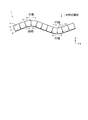
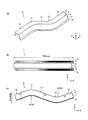
- FIG. 1 is a diagram illustrating a molding process in a press molding method according to an embodiment of the present invention ((a) blank, (b) intermediate molded product, (c) press molded product).
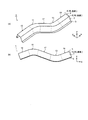
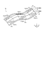
- FIG. 2 is a diagram for explaining a press-formed product which is a molding target in the present invention ((a) perspective view, (b) side view).
- FIG. 3 is a diagram for explaining the movement of a material when a press-formed product to be formed by the present invention is formed by a conventional press-forming method and a portion where tensile deformation and compression deformation occur in the press-formed product.
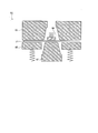
- FIG. 4 is a diagram illustrating a press-formed product in which a vertical wall portion is formed by inducing shear deformation in the background of the present invention.
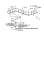
- FIG. 5 is a diagram for explaining the movement of the material when a press-formed product is formed by the press-forming method according to the embodiment of the present invention.
- FIG. 6 shows the movement of the material due to the crushing of the bead portion formed in the intermediate molded product and the movement of the material due to bending at the top plate side ridge line portion in the press molding method according to the embodiment of the present invention.
- FIG. 6 is a diagram for explaining each movement (pseudo-shear deformation) of the material in the main forming step.
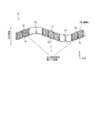
- FIG. 7: is a figure which shows the other aspect of the intermediate molded product shape
- FIG. 8 is a figure which shows the other aspect of the intermediate molded product shape
- FIG. 9 is a diagram showing a specific example of the shape of the bead portion formed in the intermediate molded product in the preforming step in the press molding method according to the present invention.
- FIG. 10 is a diagram for explaining foam forming (crash forming) applied in the press forming method according to the present invention.
- FIG. 11 is a figure explaining the foam molding using the pad (pad) applied in the press molding method which concerns on this invention.
- FIG. 12 is a diagram for explaining draw drawing applied in the press forming method according to the present invention.
- FIG. 13 is a diagram illustrating draw molding using a pad applied in the press molding method according to the present invention.
- FIG. 14 is a diagram showing a press-molded product which is a molding target in the examples ((a) perspective view, (b) top view, (c) side view).
- FIG. 15 is a cross-sectional view of a press-formed product which is a molding target in the examples.
- the X axis, the Y axis, and the Z axis in the drawings indicate the longitudinal direction, the width direction, and the height direction of the press-formed product, respectively. Further, in the present embodiment, the height direction of the press-formed product is supposed to coincide with the forming direction of the press-formed product.
- the press-formed product 1 targeted by the present invention includes a top plate portion 3, and a vertical wall portion 7 continuous from the top plate portion 3 via a top plate side ridge line portion 5, It has a hat-shaped cross section having a vertical wall portion 7 and a continuous flange portion 9, and has a convex curved portion 11 that is convexly curved in the height direction along the longitudinal direction in a side view and a concave curved portion 13 that is concavely curved. And have.
- a straight line portion 15 and a straight line portion 17 are provided on both sides in the longitudinal direction of the convex curved portion 11, and a straight line portion 17 and a straight line portion 19 are provided on both sides of the concave curved portion 13 in the longitudinal direction.
- the center of the arc curved in a convex shape in the side view is on the flange portion 9 side
- the center of the arc curved in the concave shape in the side view is on the top plate portion 3 side. It is in.
- the press-molded product to be molded in the present invention may be one that bends in the height direction along the longitudinal direction.
- the molding direction is the Z direction
- the press-molded product is Curved in the ZX plane including stroke axis, that is, curved in side view.
- Fig. 3 shows the movement of the material during molding when the press-formed product 1 is viewed from the side.
- the blank metal plate
- the blank is bent at the top plate side ridge line portion 5 between the top plate portion 3 and the vertical wall portion 7, and is orthogonal to the top plate side ridge line portion 5 (see FIG. Material moves in the direction of the arrow inside). Then, a line length difference occurs in the longitudinal direction between the flange portion 9 and the top plate portion 3.
- the top plate portion 3 and the flange portion 9 are pulled. It is considered important to reduce the line length difference in the longitudinal direction between the top plate portion 3 and the flange portion 9 by changing the movement of the material during the forming process so as not to cause the deformation or the compression deformation.
- the present inventor diligently studied a concrete method for realizing this.
- the vertical wall portions 7a, 7b, 7c of the straight line portions 15, 17, 19 are formed.
- the material should be subjected to shear deformation so as to be molded.
- the top plate portion 3 and the flange portion 9 are strongly sandwiched and the shear force is applied to the vertical wall portions 7a, 7b, 7c.
- the step of forming the press-formed product 1 is divided into two steps.
- a shape for controlling the movement of the material that undergoes shear deformation in the forming process of the vertical wall portions 7a, 7b, 7c is formed.
- the second step it was conceived that the vertical wall portions 7a, 7b, 7 should be formed by inducing a pseudo-shear deformation in the portion provided with the shape for controlling the movement of the material.
- the present invention has been made based on the above studies, and the press molding method according to the embodiment of the present invention will be described below.
- the press molding method according to the present embodiment is for molding the press molded product 1 shown in FIG. 2, and as shown in FIG. 1, a preforming step of preforming the blank 21 into an intermediate molded product 31.
- the main molding step of molding the intermediate molded product 31 into the press molded product 1 is provided. The above steps will be described below.
- the preforming step is a step of preforming the blank 21 into an intermediate molded product 31.
- the intermediate molded product 31 includes the convex curved portion 11 of the press molded product 1.
- Vertical wall equivalent surface portions 33a and 33b which are portions corresponding to the vertical wall portions 7a and 7b (see FIG. 1C) in the straight portions 15 and 17 on both sides in the longitudinal direction with the concave curved portion 13 interposed therebetween.
- Corresponding to the vertical wall-corresponding surface portions 33b and 33c which are the portions corresponding to the vertical wall portions 7b and 7c (see FIG. 1C) in the straight line portions 17 and 19 on both sides in the longitudinal direction, and to the top plate side ridge line portion 5.
- the bead portion 37 (37a, 37b, 37c) that is inclined with respect to the base line 35 is formed.
- the bead portions 37a and 37b formed on the vertical wall-corresponding surface portions 33a and 33b on both sides in the longitudinal direction with the convex curved portion 11 interposed therebetween are located on the major curved convex portion 11 side of the bead portions 37a and 37b.
- the end portions 37a2 and 37b1 are separated from the base line 35, and the end portions 37a1 and 37b2 located on the opposite side are inclined so as to approach the base line 35.
- the bead portions 37b and 37c formed on the vertical wall-corresponding surface portions 33b and 33c on both sides in the longitudinal direction with the concave curved portion 13 sandwiched therebetween are ends located on the major curved concave curved portion 13 side of the bead portions 37b and 37c.
- the portions 37b2 and 37c1 approach the base line 35, and the end portions 37b1 and 37c2 located on the opposite side are inclined so as to move away from the base line 35.
- the acute angle side of the angle formed by the major axis of the bead portion 37 and the base line 35 in the vertical wall equivalent surface portion 33 where the bead portion 37 is formed. It is desirable that the angle ⁇ is in the range of 5° to 60°. Further, as shown in FIG. 5(b), when an angle on the acute angle side of the angle formed by the molding direction of the press-formed product 1 and the top plate side ridge line portion 5 in the main molding step described later is ⁇ 1 , the angle ⁇ formed by the major axis of the bead portion 37 and the base line 35 preferably satisfies the relationship of ⁇ 2 ( 90° ⁇ 1 ). In addition, the suitable range of the angle ⁇ of the bead portion 37 will be demonstrated in Examples described later.
- the intermediate molded article 31 may be molded by using a mold for molding the press molded article 1, whereby the bead portion 37 provided in the preforming step is crushed to have a flat shape.
- the direction orthogonal to the bead portion of the bead portion 37 and the main direction is the same (see FIG. 5B)
- the bead portion 37 when the bead portion 37 is crushed in the main forming process, the bead portion 37 extends in the bead orthogonal direction most efficiently, and the vertical wall equivalent surface portion
- the pseudo shear deformation can be effectively induced in 33.
- FIG. 6 shows the movement of the material by the press molding method according to the present invention.
- the vertical wall portion 7 moves the material in a direction orthogonal to the top plate side ridge line portion 5.
- the press molding method according to the present invention when the intermediate molded product 31 molded in the preforming step is molded into the press molded product 1, the bead portion 37 formed on the vertical wall equivalent surface portion 33 is crushed. It becomes a stretched deformation. At this time, the material of the bead portion 37 moves in a direction orthogonal to the major axis of the bead portion 37 (bead orthogonal direction). As a result, as shown in FIG. 6, the press forming direction component of the movement of the material due to the bead portion 37 being crushed and the press forming direction component of the movement of the material due to bending in the ridge line orthogonal direction at the top plate side ridge line portion 5.
- the tensile deformation of the top plate portion 3 of the convex curved portion 11 is also relaxed and formed. It is possible to suppress cracks in the top plate portion 3 of the curved section 11. Further, since the press-formed product 1 is formed by relaxing the tensile deformation of the flange portion 9 of the concave curved portion 13, the compressive deformation of the top plate portion 3 of the concave curved portion 13 is mitigated, and the flange of the concave curved portion 13 is reduced. Wrinkles in the portion 9 can also be suppressed.
- Patent Document 5 pre-forms a convex or concave bead portion at a portion corresponding to a vertical wall portion of a blank, and crushes the bead portion to obtain a target press-formed product.
- it is similar to the press molding method according to the present invention at first glance.
- a bead portion is directly preformed on a portion where a crack is generated in the first step, that is, a vertical wall portion which is continuous with a flange portion where a top plate portion and wrinkles are generated, and then continued.
- the bead portion is crushed to promote the material inflow to the portion where cracks occur and the material outflow from the portion where wrinkles occur.
- a bead portion is formed on a vertical wall portion that is continuous with the top plate portion and the flange portion without cracks and wrinkles, and the bead portion is formed in the main molding step which is the second step.
- the bead portion 37 formed in the preforming step may be one that is inclined with respect to the base line 35 as described above, but the angle ⁇ of the bead portion 37 may be 5° or more and 60° or less. preferable.
- the movement of the material in the direction is synergistic, and further, the movement of the material in the direction orthogonal to the press forming due to the bead portion 37 being crushed and the material in the direction orthogonal to the press forming due to being bent in the direction orthogonal to the ridge line at the top plate side ridge line portion 5 are offset, and the amount of shear deformation of the surface portion corresponding to the vertical wall portion can be increased, so that compressive deformation of the flange portion 9 of the convex curved portion 11 and tensile deformation of the flange portion 9 of the concave curved portion 13 can be prevented. It can be further mitigated.
- the molding direction and the direction in which the bead portion is crushed and extended coincide with each other.
- the part 37 can be extended most efficiently in the bead orthogonal direction.
- the material can be moved in a desired direction during molding in the main molding process. It is possible to deal with various forming conditions and material strength of blanks used for forming.
- the present invention is not limited to the one in which the intermediate molded product 31 having a shape in which only the bead portion 37 is provided to the flat plate-shaped blank is formed in the preforming process as shown in FIG. A bead portion may be added to a shape close to the press-formed product 1 to be formed.
- a top plate portion 43 curved in a convex shape and a concave shape in the height direction, a vertical wall equivalent surface portion 47 continuous from the top plate portion 43 via a top plate side ridge line portion 45,
- the intermediate molded product 41 having the flange portion 49 and the bead portion 51 formed on the surface portion 47 corresponding to the vertical wall may be molded.
- FIG. 1 A cross-sectional view of the intermediate molded product 41 and the press molded product 1 is shown in FIG.
- the angle ⁇ of the vertical wall equivalent surface portion 47 in the intermediate molded product 41 is smaller than the angle ⁇ 0 of the vertical wall portion 7 of the press molded product 1, and the vertical wall height h of the intermediate molded product 41 is set to the vertical wall height of the press molded product 1.
- the vertical wall equivalent surface portion 47 can be molded into the vertical wall portion 7 while crushing the bead portion 51 in the main molding process.
- top plate side ridge line portion 45 in the intermediate molded product 41 has a bent shape that connects the top plate portion 43 and the vertical wall equivalent surface portion 47 (see FIG. 8 ), the top plate side ridge line portion 45 and the vertical plate side ridge line portion 45 The bead portion 51 on the wall equivalent surface portion 47 is not located on the same plane.
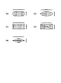
- the bead portion 37 (FIG. 1(b)) or the bead portion 51 (FIG. 7) has an oval shape in plan view (FIG. 9(a)), but the present invention has this shape.
- the shape is not limited to this, and the shape shown in FIGS. 9B to 9E may be used.
- the height and number of the bead portions formed on the intermediate molded product in the preforming step are not limited, but the height of the bead portions is increased, and by forming a larger number of the bead portions, the vertical portion where the bead portions are formed is formed.
- the cross-section line length of the wall-equivalent surface portion becomes large, the movement of the material when the bead portion is flatly formed in the main forming step can be further increased, and a better effect of reducing cracks and wrinkles can be obtained.
- the bead portion may have a convex or concave cross section orthogonal to the long axis.
- the major axis of each of the convex bead portion and the concave bead portion may be alternately formed.
- it is preferable that the major axes of the bead portions are parallel to each other.
- the position where the bead portion is formed is, like the straight line portions 15, 17, and 19 shown in FIG. 1, a portion adjacent to the convex curved portion 11 or the concave curved portion 13 where cracks or wrinkles occur, or the degree of bending is loose. It is desirable to be a part.
- the bead portion formed in the intermediate molded product may have its end portion slightly inserted into the vertical wall equivalent surface portion of the convex curved portion or the vertical wall equivalent surface portion of the concave curved portion.
- both foam forming and draw forming can be applied.
- FIG. 10 shows an example of a cross-sectional view of the mold 61 and the blank 21 in forming a foam.
- the foam molding is a method of molding by sandwiching the blank 21 with an upper die 63 and a lower punch 65, and is applicable to both the preforming step and the main forming step according to the present invention.
- a die 71 having a pad 77 as shown in FIG. 11 is used, and a die 77 is used while pressing a surface portion corresponding to a top plate portion of the blank 21 by the pad 77 which is paired with the punch bottom portion 75a of the punch 75. It is also possible to form the foam with 73 and the punch 75.
- FIG. 12 shows a cross-sectional view of the die 81 and the blank 21 in draw forming.
- the draw forming is a method of forming by lowering (relatively moving) the die 83 and the blank holder 85 toward the punch 87 side while holding the blank 21 with the die 83 and the blank holder 85, and the preforming step according to the present invention. It can be applied to both of the main molding process. Further, according to the present invention, a die 91 having a pad 99 as shown in FIG. 13 is used, and the surface of the blank 21 corresponding to the top plate portion is pressed by the pad 99 that is paired with the punch bottom portion 97a of the punch 97. Draw forming may be performed while holding the blank 21 with the die 93 and the blank holder 95.
- the press forming method according to the present invention is not limited to a steel plate, and may be a metal plate.
- a steel plate for example, coated steel sheet, aluminum sheet, aluminum alloy sheet, etc.
- a press-formed product 1 having a hat-shaped cross section having a convex curved portion 11 that is convexly curved in the height direction and a concave curved portion 13 that is concavely curved. It was supposed to be press molded.
- both the curvature radius of the convex curved portion 11 and the curvature radius of the concave curved portion 13 in the Z-axis direction are R150.
- a 1180 MPa grade steel sheet having a plate thickness of 1.2 mm was used as the material.
- an intermediate formed product was formed by the preforming process according to the present invention, and then the intermediate formed product was formed into a press-formed product by the main forming process, which was taken as an example of the present invention.
- the press forming method in the preforming step was foam forming (see FIG. 10) or draw forming (see FIG. 12), and the press forming method in the main forming step was also foam forming or draw forming.
- the case where the pad was used for the forming was also examined (see FIGS. 11 and 13).
- the blank holder load was 50 tonf, and when the pad was used, the pad load was 10 tonf.
- the preforming step includes a case where an intermediate molded product 31 having a shape in which only a bead portion 37 is applied to a flat plate-shaped blank as shown in FIG. 1B is formed, and a top plate portion as shown in FIGS. 7 and 8.
- the angle ⁇ formed by 51 and the base line corresponding to the top plate side ridge line portion 45 was 5 conditions of 3°, 5°, 20°, 60° and 70°.
- the press-molded product 1 is molded in one step without forming a bead portion in a conventional example, and the press-molded product 1 is molded in two steps of a pre-molding process and a main molding process as in the case of the present invention. Therefore, a comparative example was one in which the angle ⁇ (see FIG. 1B) of the bead portion formed in the intermediate molded product in the preforming step was outside the preferred range of the present invention.
- the formability was evaluated by the presence or absence of cracks and wrinkles in the flange portion 9 and the top plate portion 3 of the press-formed product 1.
- the evaluation of cracks the presence or absence of cracks in the top plate portion 3 of the convex curved portion 11 and the flange portion 9 of the concave curved portion 13 is observed. If cracks are present, x is determined. ), it was evaluated as ⁇ , and when there was no crack or constriction, it was evaluated as ⁇ .
- the wrinkle evaluation the presence or absence of wrinkles in the flange portion 9 of the convex curved portion 11 and the top plate portion 3 of the concave curved portion 13 is observed. When there is a noticeable wrinkle, x, when there is a small wrinkle, wrinkle is observed. When there is no such item, it is marked as ⁇ . Table 1 shows the evaluation results of molding conditions and moldability.
- [A] to [E] in the leftmost column of Table 1 show a group of invention examples and comparative examples in which the pressing method and the presence or absence of the pad in the preforming step and the main forming step are the same conditions.
- Group A is for forming a flat intermediate product 31 in the preforming step, forming the preforming step as foam, and forming the main forming step as foam, without using a pad in both the preforming step and the main forming step. (Invention Examples 1 to 5)
- the top plate portion 3 of the convex curved portion 11 and the flange portion 9 of the concave curved portion 13 are constricted due to the reduction of the plate thickness.
- the top plate portion 3 of the convex curved portion 11 and the flange portion 9 of the concave curved portion 13 were constricted due to the reduction of the plate thickness.
- Group B is to form a flat intermediate product 31 in the preforming step, form forming the preforming step, draw forming the main forming step, and use no pad in both the preforming step and the main forming step.
- the flat intermediate product 31 is formed in the preforming step, the preforming step is form forming, the main forming step is form forming, the preforming step is no pad, and the main forming step is with pad. (Examples 21 to 25 of the invention).
- the top plate portion 3 of the convex curved portion 11 is constricted due to the reduction of the plate thickness, and the flange of the concave curved portion 13 is formed.
- the part 9 was cracked.
- the top plate portion 3 of the convex curved portion 11 and the flange portion 9 of the concave curved portion 13 were constricted.
- Group D is to form a flat intermediate product 31 in the preforming step, the preforming step is foam forming, the main forming step is draw forming, the preforming step is no pad, and the main forming step is with pad. (Invention example 31 to invention example 35).
- Group E is for forming the intermediate molded product 41 in which the angle ⁇ of the vertical wall equivalent surface portion 47 is 30° in the preforming step, the preforming step is without a pad, and the main forming step is with a pad ( Invention Example 41 to Invention Example 45).
- the top plate portion, the vertical wall portion and the flange portion when press-molding a press-formed product curved in a convex shape and a concave shape in the height direction along the longitudinal direction in a side view, cracks and It is possible to provide a press molding method capable of obtaining a good press molded product without causing wrinkles.
- Top plate part 5 Top plate side ridge line part 7, 7a, 7b, 7c Vertical wall part 9 Flange part 11 Convex curved part 13 Concave curved part 15, 17, 19 Straight part 21 Blank 31 Intermediate molded product 33 , 33a, 33b, 33c Vertical wall equivalent surface portion 35 Base line 37, 37a, 37b, 37c Bead portion 37a1, 37a2, 37b1, 37b2, 37c1, 37c2 End portion 41 Intermediate molded product 43
- Top plate portion 45 Top plate side ridge portion 47, 47a, 47b, 47c Vertical wall equivalent surface portion 49 Flange portion 51, 51a, 51b, 51c Bead portion 61 Mold (form molding) 63 die 65 punch 71 mold (form molding) 73 Die 75 Punch 75a Punch Bottom 77 Pad 81 Mold (Draw Molding) 83 Die 85 Blank Holder 87 Punch 91 Mold (Draw Molding) 93 die 95 blank holder 97 punch 97a punch bottom 99 pad
Abstract
A press forming method according to the present invention is a method for forming a press formed product 1 having a top plate section 3, vertical wall sections 7, flange sections 9, and a protruding curved site 11 curved in a protruding manner and a recessed curved site 13 curved in a recessed manner in the height direction. The method includes: a preforming step for forming an intermediate formed product 31 having bead parts 37 formed in a vertical wall-corresponding surface section 33 corresponding to the vertical wall sections 7 on both sides in the longitudinal direction of each of the protruding curved site 11 and the recessed curved site 13; and a main forming step for forming the press formed product 1 by crushing the bead parts 37 of the intermediate formed product 31 and thereby inducing pseudo shearing deformation in the vertical wall-corresponding surface section 33. In the preforming step, the bead parts 37 are slanted such that an end section of each bead part 37 on the protruding curved site 11 side is spaced apart from a baseline 35 corresponding to a top-plate side ridge line section 5 between the top plate section 3 and the vertical wall section 7, and such that an end section of the bead part 37 on the opposite side is closer to the baseline 35.
Description
本発明は、プレス成形(press forming)方法に関し、特に、天板部(top portion)、縦壁部(side wall portion)及びフランジ部(flange portion)を有し、側面視で長手方向に沿って高さ方向に凸状及び凹状に湾曲するプレス成形品を成形するプレス成形方法に関する。
The present invention relates to a press forming method, and in particular, has a top plate portion, a side wall portion, and a flange portion, and is along a longitudinal direction in a side view. The present invention relates to a press molding method for molding a press molded product that is curved in a convex shape and a concave shape in the height direction.
プレス成形とは、鋼板(steel sheet)などの金属材料(metallic material)を金型(die of press forming)で挟圧することにより、金型の形状を転写して加工を行う方法のことである。特に、自動車部品(automotive parts)の多くはプレス成形により作製されている。昨今では、自動車車体の軽量化(weight reduction of automotive body)の観点から車体部品(automotive body part)に高強度な鋼板(high-strength steel sheet)(高張力鋼板(high-tension steel sheet))を使用する傾向が強くなっている。鋼板やその他金属材料の特性として、強度が増すと延性(elongation)は乏しくなる傾向となる。これにより、高張力鋼板のプレス成形では割れ(fracture)やしわ(wrinkles)といった成形不良がしばしば発生し問題となっている。
▽Press molding is a method of transferring the shape of the mold by pressing metal material such as steel sheet with a die of press forming to perform processing. In particular, many automotive parts are made by press molding. Nowadays, from the viewpoint of weight reduction of automotive body, high-strength steel sheet (high-tension steel sheet) is used for vehicle body part. The tendency to use is becoming stronger. As a characteristic of steel plates and other metallic materials, as the strength increases, the ductility (elongation) tends to become poor. As a result, in press forming of high-strength steel sheets, forming defects such as fracture and wrinkles often occur, which is a problem.
自動車の骨格部品(structural parts)の中で、リアサイドメンバ(rear side member)やフロアクロス(floor cross)など急峻に湾曲(curve)した形状を有する湾曲部品は、割れやしわが発生しやすく難成形部品とされている。最近では自動車会社・部品会社はさらなる軽量化を目指して、それらの湾曲部品に高張力鋼板を適用する検討がされており、割れ・しわをいかに抑制しながらプレス成形を行うかが課題となっている。
Among structural parts of automobiles, curved parts such as rear side members and floor crosses that have a sharply curved shape are prone to cracking and wrinkling and are difficult to form. It is considered as a part. Recently, automobile companies and parts companies are studying to apply high-strength steel sheets to their curved parts with the aim of further weight reduction, and the issue is how to press-form while suppressing cracks and wrinkles. There is.
割れやしわを抑制して湾曲部品をプレス成形する技術がこれまでにいくつか提案されている。例えば、特許文献1には、上面視で湾曲したL字部品(L-shaped part)のプレス成形において、フランジと縦壁を成形する成形力を利用し材料のパンチ(punch)底面でスライド(slide)させて成形することにより、パンチ底のしわとフランジの割れを回避する技術が開示されている。
Some technologies have been proposed so far to press-form curved parts while suppressing cracks and wrinkles. For example, in Patent Document 1, in press molding of an L-shaped part that is curved in a top view, the molding force for molding a flange and a vertical wall is used to slide on a bottom surface of a material punch. ) And forming, thereby avoiding wrinkles on the bottom of the punch and cracks on the flange.
また、特許文献2には、長手方向に湾曲した断面ハット状(hat-shaped cross section)の湾曲プレス部品のプレス成形において、予備成形でブランク材(blank material)の幅方向端部に折曲部を付与し、該折曲部を残した状態で前記湾曲プレス部品を成形することで、フランジ部におけるシワの発生を抑制する技術が開示されている。当該技術によれば、予備成形においてブランク材の幅方向端部に折曲部を付与することで幅方向端部の剛性(stiffness)が高くなり、長手方向に縮む力に対して対抗力が大きくなるために、湾曲形状に起因した肉余り(excess metal)によって長手方向に縮む力が作用しても、フランジ部におけるシワの発生を抑制することができるとされている。
Further, in Patent Document 2, in the press forming of a curved press part having a hat-shaped cross section that is curved in the longitudinal direction, a bending part is formed at the widthwise end of a blank material by preforming. There is disclosed a technique of suppressing the generation of wrinkles in the flange portion by forming the curved press part with the bent portion left. According to this technique, by providing a bent portion to the widthwise end portion of the blank material in preforming, the rigidity (stiffness) of the widthwise end portion is increased, and the counter force against the force contracting in the longitudinal direction is large. Therefore, it is said that it is possible to suppress the occurrence of wrinkles in the flange portion even if the force of contracting in the longitudinal direction due to the excess metal due to the curved shape acts.
さらに、割れやしわの発生を抑制することを目的とし、ビード(bead)を付与して湾曲部品をプレス成形する技術がいくつか提案されている。特許文献3には、素材(blank material)の端部を平面視したときに曲率(curvature)を有し、かつ側面視したときに縦壁面の下方にフランジ面を有する形状に1工程でプレス加工するに際し、縦壁面に凸状ビードを付与し、その直下のフランジ面には凹状ビードを付与することにより、素材成形部のしわ発生を抑制する技術が開示されている。
Furthermore, several technologies have been proposed to press-form curved parts by adding beads for the purpose of suppressing the occurrence of cracks and wrinkles. In Patent Document 3, a blank material has a curvature when viewed in a plan view, and has a flange surface below a vertical wall surface when viewed in side view, which is pressed in one step. In doing so, a technique is disclosed in which wrinkles are prevented from occurring in the material forming portion by providing a convex bead on the vertical wall surface and a concave bead on the flange surface immediately below.
特許文献4には、平面視で湾曲する湾曲部とハット型の横断面形状とを有するプレス部品を自由曲げ工法(bend forming)により1工程でプレス加工するに際し、前記湾曲部の内周側のフランジに割れを生じさせずに前記プレス部品を製造する技術が開示されている。当該技術によれば、ブランクにおける前記湾曲部の内周側のフランジに成形される部分の近傍(外側)に凸形状のビードを成形することで、自由曲げ工法における材料の回転を促進させて該フランジ部に流入される材料の量が増加し、該フランジ部での割れを防止することができるとされている。
In Patent Document 4, when a press part having a curved portion that is curved in a plan view and a hat-shaped cross-sectional shape is pressed in one step by a free bending method (bend forming), the inner peripheral side of the curved portion is A technique for manufacturing the pressed part without causing the flange to crack is disclosed. According to the technique, by forming a bead having a convex shape in the vicinity (outer side) of a portion formed on the flange on the inner peripheral side of the curved portion in the blank, the rotation of the material in the free bending method is promoted, and It is said that the amount of material that flows into the flange portion increases, and cracks at the flange portion can be prevented.
特許文献5には、天板部と縦壁部とフランジ部とを有するプレス成形部品を、割れやフランジしわの発生位置の近傍に相当する素材の位置にビード形状を予備成形し、その後、該ビード形状を予備成形した素材からプレス成形する技術が開示されている。当該技術によれば、プレス成形部品を成形する場合に割れやフランジしわが発生する位置付近に、近傍に位置するビード形状が潰れることで、そこから材料が供給されるので、素材が延びすぎて割れが発生するのを防止できるとともに、フランジ部からの材料流入が多すぎてフランジしわが発生するのを防止できるとされている。
In Patent Document 5, a press-formed component having a top plate portion, a vertical wall portion, and a flange portion is preformed into a bead shape at a position of a material corresponding to the vicinity of a position where cracks or flange wrinkles occur, and thereafter, A technique of press-molding from a material in which a bead shape is preformed is disclosed. According to the technique, when a press-molded part is molded, the bead shape located in the vicinity is crushed in the vicinity of a position where cracks or flange wrinkles occur, so that the material is supplied from there, so that the material is excessively extended. It is said that it is possible to prevent the occurrence of cracks and the occurrence of flange wrinkles due to too much inflow of material from the flange portion.
しかしながら、特許文献1に開示されている技術では、パンチ底に座面(mounted surface)などの形状がある場合や、袋形状のような閉じられた形状である場合は材料を大きく動かすことができないため、適用可能な部品が限定的であった。また、特許文献2に開示されている技術では、フランジ部の折り曲げ形状は次工程で平坦に成形する必要があるが、曲げ癖(curl)が残存してしまうおそれがあった。特に、自動車部品の場合、フランジは他部品との接合面(joining surface)になることが多く、高い面精度が求められるため、本成形方法の適用には注意が必要であった。
However, with the technology disclosed in Patent Document 1, the material cannot be moved largely when the punch bottom has a shape such as a seated surface or when the punch has a closed shape such as a bag shape. Therefore, the applicable parts were limited. Further, in the technique disclosed in Patent Document 2, the bent shape of the flange portion needs to be formed flat in the next step, but there is a risk that the bending tendency (curl) may remain. In particular, in the case of automobile parts, the flange is often a joining surface with other parts, and high surface accuracy is required, so it was necessary to apply this molding method with caution.
また、特許文献3および特許文献4に開示されている技術はいずれも、1工程でプレス加工するものであり、しわ発生又は割れを防止するために付与したビードがそのまま残ってしまうという問題があった。さらに、特許文献5に開示されている技術では、素材に予備成形したビードを潰すことでビード直交方向の変形(deformation)を緩和するものであるが、予備成形するビードの向きや、該ビードが潰れたときの材料の流れの方向に関しては開示されておらず、割れやしわを効果的に防止することができない場合があった。
Further, both of the techniques disclosed in Patent Document 3 and Patent Document 4 perform press working in one step, and there is a problem that the bead added to prevent wrinkle generation or cracking remains as it is. It was Further, in the technique disclosed in Patent Document 5, the bead preformed on the material is crushed to reduce deformation in the direction orthogonal to the bead. However, the direction of the bead to be preformed and the bead There is no disclosure regarding the flow direction of the material when it is crushed, and it may not be possible to effectively prevent cracks and wrinkles.
本発明は、上記課題に鑑みてなされたものであって、その目的は、天板部、縦壁部及びフランジ部を有し、側面視で長手方向に沿って高さ方向に凸状及び凹状に湾曲するプレス成形品をプレス成形するに際し、割れやしわを生じさせることなく良好なプレス成形品を得ることのできるプレス成形方法を提供することにある。
The present invention has been made in view of the above problems, and an object thereof is to have a top plate portion, a vertical wall portion, and a flange portion, and have a convex shape and a concave shape in the height direction along the longitudinal direction in a side view. It is an object of the present invention to provide a press-molding method capable of obtaining a good press-molded product without causing cracks or wrinkles when press-molding a press-molded product that is curved in a vertical direction.
本発明に係るプレス成形方法は、天板部と、該天板部から天板側稜線部(ridge line)を経由して連続する縦壁部と、該縦壁部から連続するフランジ部とを有し、側面視で長手方向に沿って高さ方向に凸状に湾曲する凸状湾曲部位(curved portion)と凹状に湾曲する凹状湾曲部位とを有するプレス成形品を成形するものであって、前記凸状湾曲部位を挟んで長手方向両側の部位における前記縦壁部に相当する面部と、前記凹状湾曲部位を挟んで長手方向両側の部位における前記縦壁部に相当する面部とに、前記天板側稜線部に相当する基線(baseline)に対して傾斜して延在する凸形状及び/又は凹形状のビード部が形成された中間成形品(preformed part)を成形する予成形工程(preformed process)と、該中間成形品における前記ビード部を押し潰して前記縦壁部に相当する面部を該ビード部の長軸に直交するビード直交方向に伸ばすことで、該縦壁部に相当する面部に擬似せん断変形(pseudo shear deformation)を誘発して前記プレス成形品を成形する本成形工程(main forming process)と、を備え、前記予成形工程において、前記凸状湾曲部位を挟んで形成されたビード部は、該ビード部の長軸の凸状湾曲部位側に位置する端部が前記基線から離れ反対側に位置する端部が前記基線に近づくように傾斜し、前記凹状湾曲部位を挟んで形成されたビード部は、該ビード部の長軸の凹状湾曲部位側に位置する端部が前記基線に近づき反対側に位置する端部が前記基線から離れるように傾斜していることを特徴とするものである。
The press molding method according to the present invention includes a top plate portion, a vertical wall portion continuous from the top plate portion via a top plate side ridge line, and a flange portion continuous from the vertical wall portion. A press-formed product having a convex curved portion (curved portion) curved in a height direction along a longitudinal direction in a side view and a concave curved portion curved in a concave shape. The surface portions corresponding to the vertical wall portions on both sides in the longitudinal direction with the convex curved portion interposed therebetween and the surface portions corresponding to the vertical wall portions on both sides in the longitudinal direction with the concave curved portion interposed therebetween. A preformed process for molding an intermediate molded product (preformed part) in which a convex and/or concave bead portion extending obliquely with respect to a baseline corresponding to the plate-side ridge is formed. ) And crushing the bead portion in the intermediate molded product to extend a surface portion corresponding to the vertical wall portion in a bead orthogonal direction orthogonal to a long axis of the bead portion, thereby forming a surface portion corresponding to the vertical wall portion. A bead formed by sandwiching the convex curved portion in the preforming step, which comprises a main forming process of inducing pseudo shear deformation to form the press-formed product. The part is inclined so that the end located on the convex curved part side of the major axis of the bead part is away from the base line and the end located on the opposite side approaches the base line, and the part is formed sandwiching the concave curved part. The bead portion is characterized in that the end portion located on the concave curved portion side of the major axis of the bead portion approaches the base line and the end portion located on the opposite side is inclined away from the base line. It is a thing.
本発明に係るプレス成形方法は、上記発明において、前記予成形工程において形成される前記ビード部は、該ビード部の長軸と前記基線とのなす角度θが、5°以上60°以下であることを特徴とするものである。
In the press molding method according to the present invention, in the above invention, in the bead portion formed in the preforming step, an angle θ between a major axis of the bead portion and the base line is 5° or more and 60° or less. It is characterized by that.
本発明に係るプレス成形方法は、上記発明において、前記ビード部の長軸と前記基線とのなす角度θは、前記本成形工程における前記プレス成形品の成形方向と前記天板側稜線部とのなす角度のうち鋭角側の角度をθ1としたとき、θ≧90°-θ1の関係を満たすことを特徴とするものである。
The press molding method according to the present invention, in the above invention, the angle θ formed by the major axis of the bead portion and the base line is defined by the molding direction of the press molded product in the main molding step and the top plate side ridge line portion. When the angle on the acute angle side among the formed angles is θ 1 , the relationship of θ≧90°−θ 1 is satisfied.
本発明に係るプレス成形方法によれば、凸状湾曲部位及び凹状湾曲部位に隣接する部位の縦壁部が擬似せん断変形を受けて成形されることにより凸状湾曲部位及び凹状湾曲部位における圧縮変形又は引張変形を低減できるので、天板部、縦壁部及びフランジ部を有して側面視で長手方向に沿って高さ方向に凸状及び凹状に湾曲するプレス成形品をプレス成形するに際し、割れやしわを生じさせることなく良好なプレス成形品を得ることができる。
According to the press molding method of the present invention, the vertical wall portion of the portion adjacent to the convex curved portion and the concave curved portion is subjected to pseudo-shear deformation to be molded, and thereby the compressive deformation of the convex curved portion and the concave curved portion. Or, since tensile deformation can be reduced, when press-molding a press-formed product that has a top plate portion, a vertical wall portion, and a flange portion and is curved convexly and concavely in the height direction along the longitudinal direction in a side view, A good press-formed product can be obtained without causing cracks or wrinkles.
本発明の実施の形態に係るプレス成形方法を説明するに先立って、本発明で成形対象とするプレス成形品と、該プレス成形品を成形する際に割れやしわが発生する理由、さらには、本発明に至った経緯について説明する。なお、図面におけるX軸、Y軸及びZ軸はそれぞれ、プレス成形品の長手方向、幅方向及び高さ方向を示すものである。また、本実施の形態においては、プレス成形品の高さ方向は、該プレス成形品の成形方向と一致するものとしている。
Prior to explaining the press-molding method according to the embodiment of the present invention, the press-molded product to be molded in the present invention, the reason why cracks and wrinkles occur when molding the press-molded product, further, The background of the invention will be described. The X axis, the Y axis, and the Z axis in the drawings indicate the longitudinal direction, the width direction, and the height direction of the press-formed product, respectively. Further, in the present embodiment, the height direction of the press-formed product is supposed to coincide with the forming direction of the press-formed product.
<プレス成形品>
本発明で対象とするプレス成形品1は、図2に一例として示すように、天板部3と、天板部3から天板側稜線部5を経由して連続する縦壁部7と、縦壁部7から連続するフランジ部9とを有する断面ハット形状であり、側面視で長手方向に沿って高さ方向に凸状に湾曲する凸状湾曲部位11と凹状に湾曲する凹状湾曲部位13とを有するものである。そして、凸状湾曲部位11の長手方向両側には直線部15及び直線部17が設けられ、凹状湾曲部位13の長手方向両側には直線部17及び直線部19が設けられている。なお、凸状湾曲部位11は、側面視において凸状に湾曲した円弧の中心がフランジ部9側にあり、凹状湾曲部位13は、側面視において凹状に湾曲した円弧の中心が天板部3側にある。 <Press-formed products>
As shown in FIG. 2 as an example, the press-formedproduct 1 targeted by the present invention includes a top plate portion 3, and a vertical wall portion 7 continuous from the top plate portion 3 via a top plate side ridge line portion 5, It has a hat-shaped cross section having a vertical wall portion 7 and a continuous flange portion 9, and has a convex curved portion 11 that is convexly curved in the height direction along the longitudinal direction in a side view and a concave curved portion 13 that is concavely curved. And have. A straight line portion 15 and a straight line portion 17 are provided on both sides in the longitudinal direction of the convex curved portion 11, and a straight line portion 17 and a straight line portion 19 are provided on both sides of the concave curved portion 13 in the longitudinal direction. In the convex curved portion 11, the center of the arc curved in a convex shape in the side view is on the flange portion 9 side, and in the concave curved portion 13, the center of the arc curved in the concave shape in the side view is on the top plate portion 3 side. It is in.
本発明で対象とするプレス成形品1は、図2に一例として示すように、天板部3と、天板部3から天板側稜線部5を経由して連続する縦壁部7と、縦壁部7から連続するフランジ部9とを有する断面ハット形状であり、側面視で長手方向に沿って高さ方向に凸状に湾曲する凸状湾曲部位11と凹状に湾曲する凹状湾曲部位13とを有するものである。そして、凸状湾曲部位11の長手方向両側には直線部15及び直線部17が設けられ、凹状湾曲部位13の長手方向両側には直線部17及び直線部19が設けられている。なお、凸状湾曲部位11は、側面視において凸状に湾曲した円弧の中心がフランジ部9側にあり、凹状湾曲部位13は、側面視において凹状に湾曲した円弧の中心が天板部3側にある。 <Press-formed products>
As shown in FIG. 2 as an example, the press-formed
このように、本発明で成形対象とするプレス成形品は、長手方向に沿って高さ方向に湾曲するものであればよく、成形方向をZ方向とすると、プレス成形品は、プレス軸(press stroke axis)を含んだZX平面で湾曲、つまり、側面視で湾曲する形状のものとする。
As described above, the press-molded product to be molded in the present invention may be one that bends in the height direction along the longitudinal direction. When the molding direction is the Z direction, the press-molded product is Curved in the ZX plane including stroke axis, that is, curved in side view.
プレス成形品1を側面から見たときの成形中における材料の動きを図3に示す。ブランク(金属板)をプレス成形すると、該ブランクは天板部3と縦壁部7との間の天板側稜線部5で曲げられ、天板側稜線部5に対して直交方向(図3中の矢印の向き)に材料が動く。そして、フランジ部9と天板部3とでは、長手方向の線長差が生じる。
Fig. 3 shows the movement of the material during molding when the press-formed product 1 is viewed from the side. When the blank (metal plate) is press-molded, the blank is bent at the top plate side ridge line portion 5 between the top plate portion 3 and the vertical wall portion 7, and is orthogonal to the top plate side ridge line portion 5 (see FIG. Material moves in the direction of the arrow inside). Then, a line length difference occurs in the longitudinal direction between the flange portion 9 and the top plate portion 3.
これにより、凸状湾曲部位11においては、天板部3では引張変形(tensile deformation)が作用して割れが生じやすく、フランジ部9では圧縮変形(compressive deformation)が作用してしわが生じやすい。その逆に、凹状湾曲部位13においては、天板部3では圧縮変形が作用してしわが生じやすく、フランジ部9では引張変形が作用して割れが生じやすい。
Due to this, in the convex curved portion 11, tensile deformation (tensile deformation) easily acts on the top plate 3 and cracks easily occur, and compressive deformation (compressive deformation) easily acts on the flange 9 and wrinkles easily occur. On the contrary, in the concave curved portion 13, the top plate portion 3 is apt to be subjected to compressive deformation to cause wrinkles, and the flange portion 9 is apt to be subjected to tensile deformation to cause cracking.
このことから、プレス成形品1を成形する際に割れやしわの発生を抑制するためには、凸状湾曲部位11及び凹状湾曲部位13の成形過程において、天板部3やフランジ部9に引張変形や圧縮変形を生じさせないように成形過程における材料の動きを変えることで、天板部3とフランジ部9とで生じる長手方向の線長差を低減することが重要と考えられる。
From this, in order to suppress the occurrence of cracks and wrinkles when molding the press-formed product 1, in the process of forming the convex curved portion 11 and the concave curved portion 13, the top plate portion 3 and the flange portion 9 are pulled. It is considered important to reduce the line length difference in the longitudinal direction between the top plate portion 3 and the flange portion 9 by changing the movement of the material during the forming process so as not to cause the deformation or the compression deformation.
そこで、本発明者は、これを実現する具体的な方法を鋭意検討した。その結果、天板部3とフランジ部9とで生じる長手方向の線長差を低減するためには、図4に示すように、直線部15、17、19における縦壁部7a、7b、7cがせん断変形を受けて成形されるようにすればよいことを着想した。そして、縦壁部7a、7b、7cがせん断変形を受けて成形されるためには、天板部3とフランジ部9を強力に挟み、縦壁部7a、7b、7cにせん断力(shear force)を加える必要があるが現実的でない。そこで、プレス成形品1を成形する工程を2つに分け、第1の工程では、縦壁部7a、7b、7cの成形過程においてせん断変形を受けるような材料の動きを制御するための形状を付与し、第2の工程では、該材料の動きを制御する形状を付与した部位に擬似的なせん断変形を誘発して縦壁部7a、7b、7を成形すればよいということに想到した。本発明は、上記検討に基づいてなされたものであり、以下、本発明の実施の形態に係るプレス成形方法について説明する。
Therefore, the present inventor diligently studied a concrete method for realizing this. As a result, in order to reduce the line length difference in the longitudinal direction between the top plate portion 3 and the flange portion 9, as shown in FIG. 4, the vertical wall portions 7a, 7b, 7c of the straight line portions 15, 17, 19 are formed. It was conceived that the material should be subjected to shear deformation so as to be molded. Then, in order to form the vertical wall portions 7a, 7b, 7c by shearing deformation, the top plate portion 3 and the flange portion 9 are strongly sandwiched and the shear force is applied to the vertical wall portions 7a, 7b, 7c. ) Need to be added, but it is not realistic. Therefore, the step of forming the press-formed product 1 is divided into two steps. In the first step, a shape for controlling the movement of the material that undergoes shear deformation in the forming process of the vertical wall portions 7a, 7b, 7c is formed. Then, in the second step, it was conceived that the vertical wall portions 7a, 7b, 7 should be formed by inducing a pseudo-shear deformation in the portion provided with the shape for controlling the movement of the material. The present invention has been made based on the above studies, and the press molding method according to the embodiment of the present invention will be described below.
<プレス成形方法>
本実施の形態に係るプレス成形方法は、図2に示すプレス成形品1を成形するものであって、図1に示すように、ブランク21を中間成形品31に予成形する予成形工程と、中間成形品31をプレス成形品1に成形する本成形工程と、を備えたものである。以下、上記各工程について説明する。 <Press molding method>
The press molding method according to the present embodiment is for molding the press moldedproduct 1 shown in FIG. 2, and as shown in FIG. 1, a preforming step of preforming the blank 21 into an intermediate molded product 31. The main molding step of molding the intermediate molded product 31 into the press molded product 1 is provided. The above steps will be described below.
本実施の形態に係るプレス成形方法は、図2に示すプレス成形品1を成形するものであって、図1に示すように、ブランク21を中間成形品31に予成形する予成形工程と、中間成形品31をプレス成形品1に成形する本成形工程と、を備えたものである。以下、上記各工程について説明する。 <Press molding method>
The press molding method according to the present embodiment is for molding the press molded
≪予成形工程≫
予成形工程は、図1(a)~(b)に示すように、ブランク21を中間成形品31に予成形する工程であり、中間成形品31は、プレス成形品1の凸状湾曲部位11を挟んで長手方向両側の直線部(straight portion)15、17における縦壁部7a、7b(図1(c)参照)に相当する部位である縦壁相当面部33a、33bと、凹状湾曲部位13を挟んで長手方向両側の直線部17、19における縦壁部7b、7c(図1(c)参照)に相当する部位である縦壁相当面部33b、33cに、天板側稜線部5に相当する基線35に対して傾斜して延在するビード部37(37a、37b、37c)が形成されたものである。 <<Preforming process>>
As shown in FIGS. 1A and 1B, the preforming step is a step of preforming the blank 21 into an intermediate molded product 31. The intermediate molded product 31 includes the convexcurved portion 11 of the press molded product 1. Vertical wall equivalent surface portions 33a and 33b, which are portions corresponding to the vertical wall portions 7a and 7b (see FIG. 1C) in the straight portions 15 and 17 on both sides in the longitudinal direction with the concave curved portion 13 interposed therebetween. Corresponding to the vertical wall-corresponding surface portions 33b and 33c, which are the portions corresponding to the vertical wall portions 7b and 7c (see FIG. 1C) in the straight line portions 17 and 19 on both sides in the longitudinal direction, and to the top plate side ridge line portion 5. The bead portion 37 (37a, 37b, 37c) that is inclined with respect to the base line 35 is formed.
予成形工程は、図1(a)~(b)に示すように、ブランク21を中間成形品31に予成形する工程であり、中間成形品31は、プレス成形品1の凸状湾曲部位11を挟んで長手方向両側の直線部(straight portion)15、17における縦壁部7a、7b(図1(c)参照)に相当する部位である縦壁相当面部33a、33bと、凹状湾曲部位13を挟んで長手方向両側の直線部17、19における縦壁部7b、7c(図1(c)参照)に相当する部位である縦壁相当面部33b、33cに、天板側稜線部5に相当する基線35に対して傾斜して延在するビード部37(37a、37b、37c)が形成されたものである。 <<Preforming process>>
As shown in FIGS. 1A and 1B, the preforming step is a step of preforming the blank 21 into an intermediate molded product 31. The intermediate molded product 31 includes the convex
そして、凸状湾曲部位11を挟んで長手方向両側となる縦壁相当面部33a、33bに形成されたビード部37a、37bは、ビード部37a、37bの長軸の凸状湾曲部位11側に位置する端部37a2、37b1が基線35から離れ、反対側に位置する端部37a1、37b2が基線35に近づくように傾斜している。さらに、凹状湾曲部位13を挟んで長手方向両側となる縦壁相当面部33b、33cに形成されたビード部37b、37cは、ビード部37b、37cの長軸の凹状湾曲部位13側に位置する端部37b2、37c1が基線35に近づき、反対側に位置する端部37b1、37c2が基線35から離れるように傾斜している。
The bead portions 37a and 37b formed on the vertical wall-corresponding surface portions 33a and 33b on both sides in the longitudinal direction with the convex curved portion 11 interposed therebetween are located on the major curved convex portion 11 side of the bead portions 37a and 37b. The end portions 37a2 and 37b1 are separated from the base line 35, and the end portions 37a1 and 37b2 located on the opposite side are inclined so as to approach the base line 35. Further, the bead portions 37b and 37c formed on the vertical wall-corresponding surface portions 33b and 33c on both sides in the longitudinal direction with the concave curved portion 13 sandwiched therebetween are ends located on the major curved concave curved portion 13 side of the bead portions 37b and 37c. The portions 37b2 and 37c1 approach the base line 35, and the end portions 37b1 and 37c2 located on the opposite side are inclined so as to move away from the base line 35.
なお、ビード部37の傾斜角度については、図1(b)に示すように、ビード部37が形成される縦壁相当面部33においてビード部37の長軸と基線35のなす角度のうち鋭角側の角度θが5°から60°の範囲であることが望ましい。さらには、図5(b)に示すように、後述する本成形工程におけるプレス成形品1の成形方向と天板側稜線部5とのなす角度のうち鋭角側の角度をθ1としたとき、ビード部37の長軸と基線35のなす角度θは、θ≧θ2(=90°-θ1)の関係を満たすことが望ましい。なお、ビード部37の角度θの好適範囲については、後述する実施例にて実証する。
As for the inclination angle of the bead portion 37, as shown in FIG. 1B, the acute angle side of the angle formed by the major axis of the bead portion 37 and the base line 35 in the vertical wall equivalent surface portion 33 where the bead portion 37 is formed. It is desirable that the angle θ is in the range of 5° to 60°. Further, as shown in FIG. 5(b), when an angle on the acute angle side of the angle formed by the molding direction of the press-formed product 1 and the top plate side ridge line portion 5 in the main molding step described later is θ 1 , The angle θ formed by the major axis of the bead portion 37 and the base line 35 preferably satisfies the relationship of θ≧θ 2 (=90°−θ 1 ). In addition, the suitable range of the angle θ of the bead portion 37 will be demonstrated in Examples described later.
≪本成形工程≫
本成形工程は、図1(b)~(c)に示すように、中間成形品31におけるビード部37を押し潰し、縦壁相当面部33をビード部37の長軸に直交するビード直交方向に伸ばすことで、縦壁相当面部33に擬似せん断変形を誘発してプレス成形品1を成形する工程である。 <<Main molding process>>
In the main molding step, as shown in FIGS. 1B to 1C, thebead portion 37 of the intermediate molded product 31 is crushed and the vertical wall equivalent surface portion 33 is moved in a bead orthogonal direction orthogonal to the major axis of the bead portion 37. This is a step of forming the press-formed product 1 by inducing pseudo-shear deformation in the vertical wall equivalent surface portion 33 by stretching.
本成形工程は、図1(b)~(c)に示すように、中間成形品31におけるビード部37を押し潰し、縦壁相当面部33をビード部37の長軸に直交するビード直交方向に伸ばすことで、縦壁相当面部33に擬似せん断変形を誘発してプレス成形品1を成形する工程である。 <<Main molding process>>
In the main molding step, as shown in FIGS. 1B to 1C, the
本成形工程では、プレス成形品1の成形用の金型を用いて中間成形品31を成形対象とすればよく、これにより、予成形工程で付与されたビード部37は潰されて平坦な形状となる。さらに、前述のとおり、予成形工程においてビード部37の長軸と基線35のなす角度θが、θ=θ2である場合(図5(b)参照)、ビード部37のビード直交方向と本成形工程における成形方向とが一致するため(図5(b)参照)、本成形工程においてビード部37が押し潰されたときに最も効率良くビード部37がビード直交方向に伸び、縦壁相当面部33に擬似せん断変形を効果的に誘発することができる。
In the main molding step, the intermediate molded article 31 may be molded by using a mold for molding the press molded article 1, whereby the bead portion 37 provided in the preforming step is crushed to have a flat shape. Becomes Further, as described above, in the preforming step, when the angle θ formed by the major axis of the bead portion 37 and the base line 35 is θ=θ 2 (see FIG. 5(b)), the direction orthogonal to the bead portion of the bead portion 37 and the main direction. Since the forming direction in the forming process is the same (see FIG. 5B), when the bead portion 37 is crushed in the main forming process, the bead portion 37 extends in the bead orthogonal direction most efficiently, and the vertical wall equivalent surface portion The pseudo shear deformation can be effectively induced in 33.
次に、本発明における割れ及びしわ低減効果のメカニズムを説明する。図6に、本発明に係るプレス成形方法による材料の動きを示す。通常のプレス成形方法では、前述のように、材料(ブランク)は天板側稜線部5で曲げられるため、縦壁部7は、天板側稜線部5に対して直交方向に材料が移動するように成形される(図3)。
Next, the mechanism of the effect of reducing cracks and wrinkles in the present invention will be described. FIG. 6 shows the movement of the material by the press molding method according to the present invention. In the normal press molding method, since the material (blank) is bent at the top plate side ridge line portion 5 as described above, the vertical wall portion 7 moves the material in a direction orthogonal to the top plate side ridge line portion 5. (FIG. 3).
これに対し、本発明に係るプレス成形方法では、予成形工程で成形された中間成形品31をプレス成形品1に成形する際、縦壁相当面部33に形成されたビード部37は潰されて伸ばされる変形となる。このとき、ビード部37の材料は、ビード部37の長軸に直交する方向(ビード直交方向)に移動する。これにより、図6に示すように、ビード部37が潰されることによる材料の動きのプレス成形方向成分と天板側稜線部5で稜線直交方向に曲げられることによる材料の動きのプレス成形方向成分とが相乗され、さらに、ビード部37が潰されることによる材料の動きのプレス成形直交方向成分と天板側稜線部5で稜線直交方向に曲げられることによる材料の動きのプレス成形直交方向成分とが相殺されて材料が動き、縦壁部7が形成される。その結果、天板部3とフランジ部9に生じる長手方向の線長差が低減し、凹状湾曲部位13のフランジ部9における引張変形、凸状湾曲部位11のフランジ部9における圧縮変形とが緩和され、割れとしわの発生を抑制できる。
On the other hand, in the press molding method according to the present invention, when the intermediate molded product 31 molded in the preforming step is molded into the press molded product 1, the bead portion 37 formed on the vertical wall equivalent surface portion 33 is crushed. It becomes a stretched deformation. At this time, the material of the bead portion 37 moves in a direction orthogonal to the major axis of the bead portion 37 (bead orthogonal direction). As a result, as shown in FIG. 6, the press forming direction component of the movement of the material due to the bead portion 37 being crushed and the press forming direction component of the movement of the material due to bending in the ridge line orthogonal direction at the top plate side ridge line portion 5. Synergistically, and further, a component in the press forming orthogonal direction of the movement of the material due to the crushing of the bead portion 37 and a component of the press forming orthogonal direction in the movement of the material due to bending in the ridge line orthogonal direction at the top plate side ridge line portion 5. Are offset and the material moves, and the vertical wall portion 7 is formed. As a result, the line length difference in the longitudinal direction between the top plate portion 3 and the flange portion 9 is reduced, and the tensile deformation of the flange portion 9 of the concave curved portion 13 and the compressive deformation of the flange portion 9 of the convex curved portion 11 are alleviated. As a result, cracks and wrinkles can be suppressed.
さらに、凸状湾曲部位11のフランジ部9における圧縮変形が緩和されてプレス成形品1が成形されることにより、凸状湾曲部位11の天板部3における引張変形も緩和されて成形され、凸状湾曲部位11の天板部3における割れを抑制することが可能となる。また、凹状湾曲部位13のフランジ部9における引張変形が緩和されてプレス成形品1が成形されることにより、凹状湾曲部位13の天板部3における圧縮変形も緩和され、凹状湾曲部位13のフランジ部9におけるしわも抑制することが可能となる。
Further, by compressing and deforming the flange portion 9 of the convex curved portion 11 to form the press-formed product 1, the tensile deformation of the top plate portion 3 of the convex curved portion 11 is also relaxed and formed. It is possible to suppress cracks in the top plate portion 3 of the curved section 11. Further, since the press-formed product 1 is formed by relaxing the tensile deformation of the flange portion 9 of the concave curved portion 13, the compressive deformation of the top plate portion 3 of the concave curved portion 13 is mitigated, and the flange of the concave curved portion 13 is reduced. Wrinkles in the portion 9 can also be suppressed.
なお、前述の特許文献5に開示されている技術は、ブランクにおける縦壁部に相当する部位に凸状又は凹状のビード部を予成形し、該ビード部を潰して目標とするプレス成形品を成形するという点に関しては、一見すると本発明に係るプレス成形方法に似ている。
The technique disclosed in Patent Document 5 described above pre-forms a convex or concave bead portion at a portion corresponding to a vertical wall portion of a blank, and crushes the bead portion to obtain a target press-formed product. In terms of molding, it is similar to the press molding method according to the present invention at first glance.
しかしながら、特許文献5に開示されている技術は、1工程目において割れが発生する部位、すなわち天板部やしわが発生するフランジ部に連続する縦壁部に直接ビード部を予備成形し、続く2工程目において該ビード部が潰され、割れが発生する部位への材料流入としわが発生する部位からの材料流出を促進するものである。
However, in the technique disclosed in Patent Document 5, a bead portion is directly preformed on a portion where a crack is generated in the first step, that is, a vertical wall portion which is continuous with a flange portion where a top plate portion and wrinkles are generated, and then continued. In the second step, the bead portion is crushed to promote the material inflow to the portion where cracks occur and the material outflow from the portion where wrinkles occur.
これに対し、本発明に係るプレス成形方法は、割れやしわのない天板部やフランジ部に連続する縦壁部にビード部を形成し、2工程目である本成形工程において該ビード部を押し潰して該縦壁部にせん断変形を誘発することで、長手方向の圧縮変形及び引張変形を抑制し、割れとしわの発生を抑制するものである。このように、特許文献5に開示されている技術と本発明に係るプレス成形方法とでは、技術的特徴が異なるものであり、得られる作用効果にも差異がある。
On the other hand, in the press molding method according to the present invention, a bead portion is formed on a vertical wall portion that is continuous with the top plate portion and the flange portion without cracks and wrinkles, and the bead portion is formed in the main molding step which is the second step. By crushing and inducing shear deformation in the vertical wall portion, compression deformation and tensile deformation in the longitudinal direction are suppressed, and generation of cracks and wrinkles is suppressed. As described above, the technology disclosed in Patent Document 5 and the press-molding method according to the present invention have different technical characteristics, and there is also a difference in the obtained effect.
なお、予成形工程で形成するビード部37は、前述のとおり、基線35に対して傾斜しているものであればよいが、ビード部37の角度θが5°以上60°以下とすることが好ましい。
The bead portion 37 formed in the preforming step may be one that is inclined with respect to the base line 35 as described above, but the angle θ of the bead portion 37 may be 5° or more and 60° or less. preferable.
特に、θ≧θ2(=90°-θ1)の場合、ビード部37が潰されることによるプレス成形方向の材料の動きと天板側稜線部5で稜線直交方向に曲げられることによるプレス成形方向の材料の動きとが相乗され、さらに、ビード部37が潰されることによるプレス成形直交方向の材料の動きと天板側稜線部5で稜線直交方向に曲げられることによるプレス成形直交方向の材料の動きが相殺され、縦壁部に相当する面部のせん断変形量を大きくすることができるので、凸状湾曲部位11のフランジ部9における圧縮変形と凹状湾曲部位13のフランジ部9における引張変形をさらに緩和することができる。
In particular, when θ≧θ 2 (=90°−θ 1 ), the movement of the material in the press forming direction due to the bead portion 37 being crushed and the press forming due to bending at the top plate side ridge line portion 5 in the direction orthogonal to the ridge line. The movement of the material in the direction is synergistic, and further, the movement of the material in the direction orthogonal to the press forming due to the bead portion 37 being crushed and the material in the direction orthogonal to the press forming due to being bent in the direction orthogonal to the ridge line at the top plate side ridge line portion 5 Are offset, and the amount of shear deformation of the surface portion corresponding to the vertical wall portion can be increased, so that compressive deformation of the flange portion 9 of the convex curved portion 11 and tensile deformation of the flange portion 9 of the concave curved portion 13 can be prevented. It can be further mitigated.
さらに、θ=θ2(=90°-θ1)の場合、図5(b)に示すように、成形方向とビード部が押し潰されて伸びる方向とが一致するため、本成形工程においてビード部37を最も効率良くビード直交方向に伸ばすことができる。
Further, in the case of θ=θ 2 (=90°−θ 1 ), as shown in FIG. 5B, the molding direction and the direction in which the bead portion is crushed and extended coincide with each other. The part 37 can be extended most efficiently in the bead orthogonal direction.
このように、本発明は、中間成形品31においてビード部37と基線35とのなす角度θを変化させることで、本成形工程での成形中に材料を所望の方向に動かすことができるため、種々の成形条件(forming condition)や成形(forming)に供するブランクの材料強度(material strength)に対応することができる。
As described above, according to the present invention, by changing the angle θ formed by the bead portion 37 and the base line 35 in the intermediate molded product 31, the material can be moved in a desired direction during molding in the main molding process. It is possible to deal with various forming conditions and material strength of blanks used for forming.
なお、本発明は、図1(b)に示すように、平板状のブランクにビード部37のみを付与した形状の中間成形品31を予成形工程で成形するものに限られず、本成形工程で成形するプレス成形品1に近い形状のものにビード部を付与したものであってもよい。
It should be noted that the present invention is not limited to the one in which the intermediate molded product 31 having a shape in which only the bead portion 37 is provided to the flat plate-shaped blank is formed in the preforming process as shown in FIG. A bead portion may be added to a shape close to the press-formed product 1 to be formed.
例えば、図7に示すように、高さ方向に凸状及び凹状に湾曲する天板部43や、天板部43から天板側稜線部45を経由して連続する縦壁相当面部47と、フランジ部49とを有し、縦壁相当面部47にビード部51を形成された中間成形品41を成形するものであってもよい。
For example, as shown in FIG. 7, a top plate portion 43 curved in a convex shape and a concave shape in the height direction, a vertical wall equivalent surface portion 47 continuous from the top plate portion 43 via a top plate side ridge line portion 45, The intermediate molded product 41 having the flange portion 49 and the bead portion 51 formed on the surface portion 47 corresponding to the vertical wall may be molded.
中間成形品41とプレス成形品1の断面図を図8に示す。中間成形品41における縦壁相当面部47の角度φは、プレス成形品1の縦壁部7の角度φ0より小さく、中間成形品41の縦壁高さhをプレス成形品1の縦壁高さh0よりも低くすることで、本成形工程においてビード部51を押し潰しながら縦壁相当面部47を縦壁部7に成形することができる。
A cross-sectional view of the intermediate molded product 41 and the press molded product 1 is shown in FIG. The angle φ of the vertical wall equivalent surface portion 47 in the intermediate molded product 41 is smaller than the angle φ 0 of the vertical wall portion 7 of the press molded product 1, and the vertical wall height h of the intermediate molded product 41 is set to the vertical wall height of the press molded product 1. By lowering the height h 0, the vertical wall equivalent surface portion 47 can be molded into the vertical wall portion 7 while crushing the bead portion 51 in the main molding process.
また、中間成形品41における天板側稜線部45は、天板部43と縦壁相当面部47とを接続する曲げられた形状であるため(図8参照)、天板側稜線部45と縦壁相当面部47にあるビード部51とが同一平面上に位置しない。
Further, since the top plate side ridge line portion 45 in the intermediate molded product 41 has a bent shape that connects the top plate portion 43 and the vertical wall equivalent surface portion 47 (see FIG. 8 ), the top plate side ridge line portion 45 and the vertical plate side ridge line portion 45 The bead portion 51 on the wall equivalent surface portion 47 is not located on the same plane.
なお、上記の説明において、ビード部37(図1(b))又はビード部51(図7)は平面視で長円形状のものであるが(図9(a))、本発明はこの形状に限るものではなく、図9(b)~(e)に示すような形状のものであってもよい。
In the above description, the bead portion 37 (FIG. 1(b)) or the bead portion 51 (FIG. 7) has an oval shape in plan view (FIG. 9(a)), but the present invention has this shape. However, the shape is not limited to this, and the shape shown in FIGS. 9B to 9E may be used.
また、予成形工程において中間成形品に形成するビード部の高さや個数には制限はないが、ビード部の高さを高く、さらに数多いビード部を形成することで、ビード部が形成された縦壁相当面部の断面線長が大きくなり、本成形工程においてビード部を平坦に成形する際の材料の移動をより増大させることができ、割れやしわを低減するより良い効果が得られる。なお、ビード部は、長軸に直交する断面が凸形状でも凹形状のいずれであってもよい。さらには、凸形状のビード部と凹形状のビード部それぞれの長軸が交互に形成されたものであってもよい。また、ビード部の長軸は平行となるようにするとよい。
Further, the height and number of the bead portions formed on the intermediate molded product in the preforming step are not limited, but the height of the bead portions is increased, and by forming a larger number of the bead portions, the vertical portion where the bead portions are formed is formed. The cross-section line length of the wall-equivalent surface portion becomes large, the movement of the material when the bead portion is flatly formed in the main forming step can be further increased, and a better effect of reducing cracks and wrinkles can be obtained. The bead portion may have a convex or concave cross section orthogonal to the long axis. Furthermore, the major axis of each of the convex bead portion and the concave bead portion may be alternately formed. Moreover, it is preferable that the major axes of the bead portions are parallel to each other.
ビード部を形成する位置は、図1に示す直線部15、17、19のように、割れやしわが発生する凸状湾曲部位11や凹状湾曲部位13に隣接した部位や、湾曲の程度が緩い部位であることが望ましい。また、中間成形品に形成するビード部は、その端部が凸状湾曲部位の縦壁相当面部や凹状湾曲部位の縦壁相当面部に多少入り込んだものであってもよい。
The position where the bead portion is formed is, like the straight line portions 15, 17, and 19 shown in FIG. 1, a portion adjacent to the convex curved portion 11 or the concave curved portion 13 where cracks or wrinkles occur, or the degree of bending is loose. It is desirable to be a part. In addition, the bead portion formed in the intermediate molded product may have its end portion slightly inserted into the vertical wall equivalent surface portion of the convex curved portion or the vertical wall equivalent surface portion of the concave curved portion.
さらに、本発明における予成形工程と本成形工程におけるプレス工法としては、フォーム成形とドロー成形のいずれも適用することができる。
Furthermore, as the pressing method in the preforming step and the main forming step in the present invention, both foam forming and draw forming can be applied.
図10に、フォーム成形における金型61とブランク21の断面図の一例を示す。フォーム成形は、上型のダイ63と下型のパンチ65でブランク21を挟み込んで成形する工法であり、本発明に係る予成形工程と本成形工程のいずれにも適用可能である。また、本発明は、図11に示すようなパッド77を備えた金型71を用い、パンチ75のパンチ底部75aと対となるパッド77によりブランク21における天板部に相当する面部を押さえながらダイ73とパンチ75とでフォーム成形するものであってもよい。
FIG. 10 shows an example of a cross-sectional view of the mold 61 and the blank 21 in forming a foam. The foam molding is a method of molding by sandwiching the blank 21 with an upper die 63 and a lower punch 65, and is applicable to both the preforming step and the main forming step according to the present invention. Further, according to the present invention, a die 71 having a pad 77 as shown in FIG. 11 is used, and a die 77 is used while pressing a surface portion corresponding to a top plate portion of the blank 21 by the pad 77 which is paired with the punch bottom portion 75a of the punch 75. It is also possible to form the foam with 73 and the punch 75.
図12に、ドロー成形における金型81とブランク21の断面図を示す。ドロー成形は、ダイ83とブランクホルダ85とでブランク21を保持したままダイ83とブランクホルダ85をパンチ87側に下降(相対移動)させることで成形する工法であり、本発明に係る予成形工程と本成形工程のいずれにも適用可能である。また、本発明は、図13に示すようなパッド99を備えた金型91を用い、パンチ97のパンチ底部97aと対となるパッド99によりブランク21における天板部に相当する面部を押さえるとともに、ダイ93とブランクホルダ95とでブランク21を保持しながらドロー成形するものであってもよい。
FIG. 12 shows a cross-sectional view of the die 81 and the blank 21 in draw forming. The draw forming is a method of forming by lowering (relatively moving) the die 83 and the blank holder 85 toward the punch 87 side while holding the blank 21 with the die 83 and the blank holder 85, and the preforming step according to the present invention. It can be applied to both of the main molding process. Further, according to the present invention, a die 91 having a pad 99 as shown in FIG. 13 is used, and the surface of the blank 21 corresponding to the top plate portion is pressed by the pad 99 that is paired with the punch bottom portion 97a of the punch 97. Draw forming may be performed while holding the blank 21 with the die 93 and the blank holder 95.
なお、本発明に係るプレス成形方法は、鋼板のみならず、金属板であれば良い。例えば、めっき鋼板(coated steel sheet)、アルミニウム板(aluminum sheet)、アルミニウム合金板(aluminum alloy sheet)などが挙げられる。
The press forming method according to the present invention is not limited to a steel plate, and may be a metal plate. For example, coated steel sheet, aluminum sheet, aluminum alloy sheet, etc.
本発明のプレス成形方法による作用効果について、具体的なプレス成形実験を行ったので以下に説明する。
A specific press-molding experiment was carried out to explain the effect of the press-molding method of the present invention, which will be described below.
実験は、図14及び図15に示すように、高さ方向に凸状に湾曲する凸状湾曲部位11と凹状に湾曲する凹状湾曲部位13とを有して断面ハット形状のプレス成形品1をプレス成形するものとした。プレス成形品1において、凸状湾曲部位11の湾曲曲率半径(curvature radis)、凹状湾曲部位13のZ軸方向の湾曲曲率半径ともにR150である。また、凸状湾曲部位11と凹状湾曲部位13の長手方向に隣接して設けられた直線部15、17、19それぞれの縦壁部7における天板側稜線部5と成形方向とのなす角度のうち鋭角側の角度θ1(図5(b))はいずれも、70°である。なお、実験において、材料には板厚1.2mmの1180MPa級鋼板(1180MPa grade steel sheet)を使用した。
In the experiment, as shown in FIGS. 14 and 15, a press-formed product 1 having a hat-shaped cross section having a convex curved portion 11 that is convexly curved in the height direction and a concave curved portion 13 that is concavely curved. It was supposed to be press molded. In the press-formed product 1, both the curvature radius of the convex curved portion 11 and the curvature radius of the concave curved portion 13 in the Z-axis direction are R150. In addition, the angle between the top plate side ridge line portion 5 and the forming direction in the vertical wall portion 7 of each of the straight line portions 15, 17 and 19 provided adjacent to each other in the longitudinal direction of the convex curved portion 11 and the concave curved portion 13 Of these, the angle θ 1 on the acute angle side (FIG. 5B) is 70°. In the experiment, a 1180 MPa grade steel sheet having a plate thickness of 1.2 mm was used as the material.
本実施例では、本発明に係る予成形工程により中間成形品を成形し、続いて本成形工程により該中間成形品をプレス成形品に成形したものを本発明例とした。ここで、予成形工程でのプレス工法についてはフォーム成形(図10参照)又はドロー成形(図12参照)とし、本成形工程でのプレス工法についてもフォーム成形又はドロー成形とした。また、予成形工程及び本成形工程ともに、パッドを用いて成形を行った場合についても検討した(図11及び図13参照)。なお、ドロー成形においては、ブランクホルダ(blank holder)荷重(load)を50tonfとし、パッドを用いた場合においては、パッド荷重を10tonfとした。
In this example, an intermediate formed product was formed by the preforming process according to the present invention, and then the intermediate formed product was formed into a press-formed product by the main forming process, which was taken as an example of the present invention. Here, the press forming method in the preforming step was foam forming (see FIG. 10) or draw forming (see FIG. 12), and the press forming method in the main forming step was also foam forming or draw forming. In addition, in both the preforming step and the main forming step, the case where the pad was used for the forming was also examined (see FIGS. 11 and 13). In the draw forming, the blank holder load was 50 tonf, and when the pad was used, the pad load was 10 tonf.
予成形工程は、図1(b)に示すような平板状のブランクにビード部37のみを付与した形状の中間成形品31を成形する場合と、図7及び図8に示すような天板部43と縦壁相当面部47のなす角度φを30°とした中間成形品41を成形する場合の2種類とした。そして、中間成形品31及び中間成形品41のいずれにおいても、ビード部37の長軸と天板側稜線部5に相当する基線35のなす角度θ(図5(a))、及び、ビード部51と天板側稜線部45に相当する基線なす角度θは、いずれも、3°、5°、20°、60°および70°の5条件とした。
The preforming step includes a case where an intermediate molded product 31 having a shape in which only a bead portion 37 is applied to a flat plate-shaped blank as shown in FIG. 1B is formed, and a top plate portion as shown in FIGS. 7 and 8. There are two types when the intermediate molded product 41 is formed with the angle φ formed by 43 and the vertical wall equivalent surface portion 47 being 30°. Then, in both the intermediate molded product 31 and the intermediate molded product 41, the angle θ (FIG. 5(a)) formed by the major axis of the bead portion 37 and the base line 35 corresponding to the top plate side ridge portion 5 and the bead portion The angle θ formed by 51 and the base line corresponding to the top plate side ridge line portion 45 was 5 conditions of 3°, 5°, 20°, 60° and 70°.
また、ビード部を形成せずにプレス成形品1を1工程で成形するものを従来例、本発明例と同様に予成形工程と本成形工程の2工程でプレス成形品1を成形するものであって、予成形工程において中間成形品に形成するビード部の角度θ(図1(b)参照)が本発明の好適範囲外としたものを比較例とした。
Further, the press-molded product 1 is molded in one step without forming a bead portion in a conventional example, and the press-molded product 1 is molded in two steps of a pre-molding process and a main molding process as in the case of the present invention. Therefore, a comparative example was one in which the angle θ (see FIG. 1B) of the bead portion formed in the intermediate molded product in the preforming step was outside the preferred range of the present invention.
本実施例では、プレス成形品1のフランジ部9と天板部3における割れとしわの有無により成形性を評価した。割れ評価については、凸状湾曲部位11の天板部3と凹状湾曲部位13のフランジ部9における割れの有無を観察し、割れが有る場合は×、割れは無いものの板厚減少によるくびれ(necking)がある場合は△、割れ・くびれが一切無い場合は○とした。しわ評価については、凸状湾曲部位11のフランジ部9と凹状湾曲部位13の天板部3におけるしわの有無を観察し、顕著なしわが有る場合は×、微小なしわが有る場合は△、しわが一切無い場合は○とした。表1に、成形条件と成形性の評価結果を示す。
In this example, the formability was evaluated by the presence or absence of cracks and wrinkles in the flange portion 9 and the top plate portion 3 of the press-formed product 1. Regarding the evaluation of cracks, the presence or absence of cracks in the top plate portion 3 of the convex curved portion 11 and the flange portion 9 of the concave curved portion 13 is observed. If cracks are present, x is determined. ), it was evaluated as △, and when there was no crack or constriction, it was evaluated as ○. Regarding the wrinkle evaluation, the presence or absence of wrinkles in the flange portion 9 of the convex curved portion 11 and the top plate portion 3 of the concave curved portion 13 is observed. When there is a noticeable wrinkle, x, when there is a small wrinkle, wrinkle is observed. When there is no such item, it is marked as ○. Table 1 shows the evaluation results of molding conditions and moldability.

表1の最左欄に記されているA~Eは、予成形工程及び本成形工程におけるプレス工法とパッドの有無を同一の条件とした発明例及び比較例のグループを示すものである。
[A] to [E] in the leftmost column of Table 1 show a group of invention examples and comparative examples in which the pressing method and the presence or absence of the pad in the preforming step and the main forming step are the same conditions.
グループAは、予成形工程において平板状の中間成形品31を成形するものとし、予成形工程をフォーム成形、本成形工程をフォーム成形とし、予成形工程及び本成形工程ともにパッド無しとしたものである(本発明例1~本発明例5)。
Group A is for forming a flat intermediate product 31 in the preforming step, forming the preforming step as foam, and forming the main forming step as foam, without using a pad in both the preforming step and the main forming step. (Invention Examples 1 to 5)
本成形が同じパッド無しのフォーム成形により1工程でプレス成形品1を成形した従来例1は、凸状湾曲部位11の天板部3と凹状湾曲部位13のフランジ部9に板厚減少によるくびれが生じた。従来例1と比較して、本発明例1と本発明例5は、凸状湾曲部位11の天板部3と凹状湾曲部位13のフランジ部9に板厚減少によるくびれが生じた。また、本発明例2と本発明例4は、凸状湾曲部位11の天板部3には割れもくびれも生じず、凹状湾曲部位13のフランジ部9にくびれが生じた。さらに、ビード部37の角度θを20°とした本発明例3は、凸状湾曲部位11の天板部3と凹状湾曲部位13のフランジ部9に割れもくびれも生じなかった。
In the conventional example 1 in which the press-molded product 1 is molded in one step by the foam molding without pad, which is the same as the main molding, the top plate portion 3 of the convex curved portion 11 and the flange portion 9 of the concave curved portion 13 are constricted due to the reduction of the plate thickness. Has occurred. As compared with Conventional Example 1, in the present invention example 1 and the present invention example 5, the top plate portion 3 of the convex curved portion 11 and the flange portion 9 of the concave curved portion 13 were constricted due to the reduction of the plate thickness. In addition, in Inventive Example 2 and Inventive Example 4, neither cracking nor constriction occurred in the top plate portion 3 of the convex curved portion 11, and constriction occurred in the flange portion 9 of the concave curved portion 13. Furthermore, in Invention Example 3 in which the angle θ of the bead portion 37 was 20°, neither cracks nor constrictions occurred in the top plate portion 3 of the convex curved portion 11 and the flange portion 9 of the concave curved portion 13.
また、従来例1は、凸状湾曲部位11のフランジ部9と凹状湾曲部位13の天板部3に明らかにわかる大きなしわが生じた。従来例1と比較して、本発明例1、本発明例2と本発明例5は、凸状湾曲部位11のフランジ部9と凹状湾曲部位13の天板部3に微小なしわが生じた。また、本発明例3と本発明例4は、凸状湾曲部位11のフランジ部9には微小なシワは生じたが、凹状湾曲部位13の天板部3にはしわが生じなかった。
In addition, in Conventional Example 1, large wrinkles were clearly formed on the flange portion 9 of the convex curved portion 11 and the top plate portion 3 of the concave curved portion 13. Compared with the conventional example 1, in the present invention example 1, the present invention example 2, and the present invention example 5, minute wrinkles were generated in the flange portion 9 of the convex curved portion 11 and the top plate portion 3 of the concave curved portion 13. In addition, in Inventive Example 3 and Inventive Example 4, minute wrinkles were formed on the flange portion 9 of the convex curved portion 11, but no wrinkles were formed on the top plate portion 3 of the concave curved portion 13.
グループBは、予成形工程において平板状の中間成形品31を成形するものとし、予成形工程をフォーム成形、本成形工程をドロー成形とし、予成形工程及び本成形工程ともにパッド無しとしたものである(本発明例11~本発明例15)。
Group B is to form a flat intermediate product 31 in the preforming step, form forming the preforming step, draw forming the main forming step, and use no pad in both the preforming step and the main forming step. (Invention Examples 11 to 15)
本成形が同じパッド無しのドロー成形により1工程でプレス成形品1を成形した従来例2は、凸状湾曲部位11の天板部3に明らかな割れが生じた。従来例2と比較して、本発明例11、本発明例12、本発明例14と本発明例15は、凸状湾曲部位11の天板部3にくびれが生じた。
In the conventional example 2 in which the press-molded product 1 was molded in one step by draw molding without pad, which was the same as the main molding, a clear crack was generated in the top plate portion 3 of the convex curved portion 11. As compared with Conventional Example 2, in the present invention example 11, the present invention example 12, the present invention example 14 and the present invention example 15, the top plate portion 3 of the convex curved portion 11 was constricted.
また、従来例2は、凹状湾曲部位13の天板部3に明らかなしわが生じた。従来例2と比較して、本発明例11~本発明例15は、凹状湾曲部位13の天板部3に微小なしわが生じた。
Also, in Conventional Example 2, clear wrinkles were formed in the top plate portion 3 of the concave curved portion 13. Compared with Conventional Example 2, in Invention Example 11 to Invention Example 15, minute wrinkles were generated in the top plate portion 3 of the concave curved portion 13.
グループCは、予成形工程において平板状の中間成形品31を成形するものとし、予成形工程をフォーム成形、本成形工程をフォーム成形とし、予成形工程をパッド無し、本成形工程をパッド有りとしたものである(本発明例21~本発明例25)。
In group C, the flat intermediate product 31 is formed in the preforming step, the preforming step is form forming, the main forming step is form forming, the preforming step is no pad, and the main forming step is with pad. (Examples 21 to 25 of the invention).
本成形が同じパッド有りのフォーム成形により1工程でプレス成形品1を成形した従来例3は、凸状湾曲部位11の天板部3に板厚減少によるくびれが生じ、凹状湾曲部位13のフランジ部9に割れが生じた。従来例3と比較して、本発明例21と本発明例25は、凸状湾曲部位11の天板部3と凹状湾曲部位13のフランジ部9にくびれが生じた。また、本発明例22と本発明例24は、凸状湾曲部位11の天板部3には割れもくびれも生じず、凹状湾曲部位13のフランジ部9にくびれが生じた。さらに、ビード部37の角度θを20°とした本発明例23は、凸状湾曲部位11の天板部3と凹状湾曲部位13のフランジ部9に割れもくびれも生じなかった。
In the conventional example 3 in which the press-molded product 1 is molded in one step by the foam molding with the same pad as the main molding, the top plate portion 3 of the convex curved portion 11 is constricted due to the reduction of the plate thickness, and the flange of the concave curved portion 13 is formed. The part 9 was cracked. As compared with Conventional Example 3, in Invention Example 21 and Invention Example 25, the top plate portion 3 of the convex curved portion 11 and the flange portion 9 of the concave curved portion 13 were constricted. In addition, in Inventive Example 22 and Inventive Example 24, neither cracking nor constriction occurred in the top plate portion 3 of the convex curved portion 11, and constriction occurred in the flange portion 9 of the concave curved portion 13. Furthermore, in Invention Example 23 in which the angle θ of the bead portion 37 was 20°, neither cracks nor constrictions occurred in the top plate portion 3 of the convex curved portion 11 and the flange portion 9 of the concave curved portion 13.
また、従来例3は、凸状湾曲部位11のフランジ部9に明らかにわかる大きなしわが生じた。従来例3と比較して、本発明例21~本発明例25は、凸状湾曲部位11のフランジ部9に微小なしわが生じた。また、本発明例25は、凹状湾曲部位13の天板部3に微小なしわが生じた。
Also, in Conventional Example 3, large wrinkles were clearly formed on the flange portion 9 of the convex curved portion 11. Compared with Conventional Example 3, in Invention Example 21 to Invention Example 25, minute wrinkles were generated in the flange portion 9 of the convex curved portion 11. Further, in Inventive Example 25, minute wrinkles were generated in the top plate portion 3 of the concave curved portion 13.
グループDは、予成形工程において平板状の中間成形品31を成形するものとし、予成形工程をフォーム成形、本成形工程をドロー成形とし、予成形工程をパッド無し、本成形工程をパッド有りとしたものである(本発明例31~本発明例35)。
Group D is to form a flat intermediate product 31 in the preforming step, the preforming step is foam forming, the main forming step is draw forming, the preforming step is no pad, and the main forming step is with pad. (Invention example 31 to invention example 35).
本成形が同じパッド有りのドロー成形により1工程でプレス成形品1を成形した従来例4は、凸状湾曲部位11の天板部3に割れが生じて、凹状湾曲部位13のフランジ部9にくびれが生じた。従来例4と比較して、本発明例31、本発明例32、本発明例35は、凸状湾曲部位11の天板部3にくびれが生じた。また、本発明例33と本発明例34は、凸状湾曲部位11の天板部3には割れもくびれも生じなかった。
In the conventional example 4 in which the press-formed product 1 is formed in one step by draw forming with the same pad as the main forming, cracks occur in the top plate portion 3 of the convex curved portion 11 and the flange portion 9 of the concave curved portion 13 is formed. I have a neck. As compared with Conventional Example 4, in the present invention example 31, the present invention example 32, and the present invention example 35, the top plate portion 3 of the convex curved portion 11 was constricted. In addition, in Inventive Example 33 and Inventive Example 34, neither cracking nor constriction occurred in the top plate portion 3 of the convex curved portion 11.
また、従来例4は、凹状湾曲部位13の天板部3に微小なしわが生じた。従来例4と比較して、本発明例31、本発明例32、本発明例34、本発明例35は、凹状湾曲部位13の天板部3に微小なしわが生じた。また、本発明例33は、凸状湾曲部位11のフランジ部9と凹状湾曲部位13の天板部3にしわが生じなかった。
Also, in Conventional Example 4, minute wrinkles were generated in the top plate portion 3 of the concave curved portion 13. Compared with Conventional Example 4, in the present invention example 31, the present invention example 32, the present invention example 34, and the present invention example 35, minute wrinkles were generated in the top plate portion 3 of the concave curved portion 13. Further, in Invention Example 33, wrinkles did not occur in the flange portion 9 of the convex curved portion 11 and the top plate portion 3 of the concave curved portion 13.
グループEは、予成形工程において縦壁相当面部47の角度φを30°とした中間成形品41を成形するものとし、予成形工程をパッド無し、本成形工程をパッド有りとしたものである(本発明例41~本発明例45)。
Group E is for forming the intermediate molded product 41 in which the angle φ of the vertical wall equivalent surface portion 47 is 30° in the preforming step, the preforming step is without a pad, and the main forming step is with a pad ( Invention Example 41 to Invention Example 45).
本成形が同じパッド有りのフォーム成形により1工程でプレス成形品1を成形した従来例3は、凸状湾曲部位11の天板部3に板厚減少によるくびれが生じ、凹状湾曲部位13のフランジ部9に割れが生じた。従来例3と比較して、本発明例41と本発明例45は、凸状湾曲部位11の天板部3と凹状湾曲部位13のフランジ部9にくびれが生じた。また、本発明例42と本発明例44は、凹状湾曲部位13のフランジ部9にくびれが生じた。さらに、本発明例43は、凸状湾曲部位11の天板部3と凹状湾曲部位13のフランジ部9に割れもくびれも生じなかった。
In the conventional example 3 in which the press-molded product 1 is molded in one step by the foam molding with the same pad as the main molding, the top plate portion 3 of the convex curved portion 11 is constricted due to the reduction of the plate thickness, and the flange of the concave curved portion 13 is formed. The part 9 was cracked. As compared with Conventional Example 3, in the present invention example 41 and the present invention example 45, a constriction occurred in the top plate portion 3 of the convex curved portion 11 and the flange portion 9 of the concave curved portion 13. Further, in Invention Example 42 and Invention Example 44, the flange portion 9 of the concave curved portion 13 was constricted. Furthermore, in Inventive Example 43, neither the top plate portion 3 of the convex curved portion 11 nor the flange portion 9 of the concave curved portion 13 was cracked or necked.
また、従来例3は、凸状湾曲部位11のフランジ部9に明らかにわかる大きなしわが生じた。従来例3と比較して、本発明例41、本発明例42は、凸状湾曲部位11のフランジ部9に微小なしわが生じた。また、本発明例45は、凹状湾曲部位13の天板部3に微小なシワは生じた。また、本発明例43、本発明例44は、凸状湾曲部位11のフランジ部9と凹状湾曲部位13の天板部3にしわが生じなかった。
Also, in Conventional Example 3, large wrinkles were clearly formed on the flange portion 9 of the convex curved portion 11. Compared with Conventional Example 3, in Invention Example 41 and Invention Example 42, minute wrinkles were generated in the flange portion 9 of the convex curved portion 11. Further, in Inventive Example 45, minute wrinkles were generated in the top plate portion 3 of the concave curved portion 13. In addition, in Invention Example 43 and Invention Example 44, wrinkles did not occur in the flange portion 9 of the convex curved portion 11 and the top plate portion 3 of the concave curved portion 13.
さらに、予成形工程におけるパッドの有無の効果について、本発明例43と本発明例51を比較すると、予成形工程においてパッドを用いなかった本発明例43と同様に、予成形工程においてパッドを用いた本発明例51においても、凸状湾曲部位11と凹状湾曲部位13における割れとしわの双方を防止できることがわかった。
Further, comparing the effect of the presence or absence of the pad in the preforming step, when comparing the present invention example 43 and the present invention example 51, as in the present invention example 43 in which no pad was used in the preforming process, the pad was used in the preforming process. Also in the present invention example 51, it was found that both cracks and wrinkles in the convex curved portion 11 and the concave curved portion 13 can be prevented.
以上、本発明に係るプレス成形方法によれば、高さ方向に凸状及び凹状に湾曲したプレス成形品を、割れとしわの双方を抑制して成形できることが示された。
As described above, according to the press-molding method according to the present invention, it has been shown that a press-molded product having a convex shape and a concave shape in the height direction can be molded while suppressing both cracks and wrinkles.
本発明によれば、天板部、縦壁部及びフランジ部を有し、側面視で長手方向に沿って高さ方向に凸状及び凹状に湾曲するプレス成形品をプレス成形するに際し、割れやしわを生じさせることなく良好なプレス成形品を得ることのできるプレス成形方法を提供することができる。
According to the present invention, the top plate portion, the vertical wall portion and the flange portion, when press-molding a press-formed product curved in a convex shape and a concave shape in the height direction along the longitudinal direction in a side view, cracks and It is possible to provide a press molding method capable of obtaining a good press molded product without causing wrinkles.
1 プレス成形品
3 天板部
5 天板側稜線部
7、7a、7b、7c 縦壁部
9 フランジ部
11 凸状湾曲部位
13 凹状湾曲部位
15、17、19 直線部
21 ブランク
31 中間成形品
33、33a、33b、33c 縦壁相当面部
35 基線
37、37a、37b、37c ビード部
37a1、37a2、37b1、37b2、37c1、37c2 端部
41 中間成形品
43 天板部
45 天板側稜線部
47、47a、47b、47c 縦壁相当面部
49 フランジ部
51、51a、51b、51c ビード部
61 金型(フォーム成形)
63 ダイ
65 パンチ
71 金型(フォーム成形)
73 ダイ
75 パンチ
75a パンチ底部
77 パッド
81 金型(ドロー成形)
83 ダイ
85 ブランクホルダ
87 パンチ
91 金型(ドロー成形)
93 ダイ
95 ブランクホルダ
97 パンチ
97a パンチ底部
99 パッド 1 Press-formedproduct 3 Top plate part 5 Top plate side ridge line part 7, 7a, 7b, 7c Vertical wall part 9 Flange part 11 Convex curved part 13 Concave curved part 15, 17, 19 Straight part 21 Blank 31 Intermediate molded product 33 , 33a, 33b, 33c Vertical wall equivalent surface portion 35 Base line 37, 37a, 37b, 37c Bead portion 37a1, 37a2, 37b1, 37b2, 37c1, 37c2 End portion 41 Intermediate molded product 43 Top plate portion 45 Top plate side ridge portion 47, 47a, 47b, 47c Vertical wall equivalent surface portion 49 Flange portion 51, 51a, 51b, 51c Bead portion 61 Mold (form molding)
63 die 65punch 71 mold (form molding)
73Die 75 Punch 75a Punch Bottom 77 Pad 81 Mold (Draw Molding)
83Die 85 Blank Holder 87 Punch 91 Mold (Draw Molding)
93 die 95blank holder 97 punch 97a punch bottom 99 pad
3 天板部
5 天板側稜線部
7、7a、7b、7c 縦壁部
9 フランジ部
11 凸状湾曲部位
13 凹状湾曲部位
15、17、19 直線部
21 ブランク
31 中間成形品
33、33a、33b、33c 縦壁相当面部
35 基線
37、37a、37b、37c ビード部
37a1、37a2、37b1、37b2、37c1、37c2 端部
41 中間成形品
43 天板部
45 天板側稜線部
47、47a、47b、47c 縦壁相当面部
49 フランジ部
51、51a、51b、51c ビード部
61 金型(フォーム成形)
63 ダイ
65 パンチ
71 金型(フォーム成形)
73 ダイ
75 パンチ
75a パンチ底部
77 パッド
81 金型(ドロー成形)
83 ダイ
85 ブランクホルダ
87 パンチ
91 金型(ドロー成形)
93 ダイ
95 ブランクホルダ
97 パンチ
97a パンチ底部
99 パッド 1 Press-formed
63 die 65
73
83
93 die 95
Claims (3)
- 天板部と、該天板部から天板側稜線部を経由して連続する縦壁部と、該縦壁部から連続するフランジ部とを有し、側面視で長手方向に沿って高さ方向に凸状に湾曲する凸状湾曲部位と凹状に湾曲する凹状湾曲部位とを有するプレス成形品を成形するものであって、
前記凸状湾曲部位を挟んで長手方向両側の部位における前記縦壁部に相当する面部と、前記凹状湾曲部位を挟んで長手方向両側の部位における前記縦壁部に相当する面部とに、前記天板側稜線部に相当する基線に対して傾斜して延在する凸形状及び/又は凹形状のビード部が形成された中間成形品を成形する予成形工程と、
該中間成形品における前記ビード部を押し潰して前記縦壁部に相当する面部を該ビード部の長軸に直交するビード直交方向に伸ばすことで、該縦壁部に相当する面部に擬似せん断変形を誘発して前記プレス成形品を成形する本成形工程と、を備え、
前記予成形工程において、前記凸状湾曲部位を挟んで形成されたビード部は、該ビード部の長軸の凸状湾曲部位側に位置する端部が前記基線から離れ反対側に位置する端部が前記基線に近づくように傾斜し、前記凹状湾曲部位を挟んで形成されたビード部は、該ビード部の長軸の凹状湾曲部位側に位置する端部が前記基線に近づき反対側に位置する端部が前記基線から離れるように傾斜していることを特徴とするプレス成形方法。 It has a top plate part, a vertical wall part continuous from the top plate part via a top plate side ridge line part, and a flange part continuous from the vertical wall part, and has a height along the longitudinal direction in a side view. A method for molding a press-formed product having a convex curved portion curved convexly in a direction and a concave curved portion curved concavely,
The surface portions corresponding to the vertical wall portions on both sides in the longitudinal direction with the convex curved portion interposed therebetween and the surface portions corresponding to the vertical wall portions on both sides in the longitudinal direction with the concave curved portion interposed therebetween. A preforming step of forming an intermediate formed article in which a bead portion having a convex shape and/or a concave shape extending obliquely with respect to a base line corresponding to the plate side ridge line portion is formed;
By crushing the bead portion of the intermediate molded product and extending the surface portion corresponding to the vertical wall portion in the bead orthogonal direction orthogonal to the long axis of the bead portion, pseudo shear deformation is applied to the surface portion corresponding to the vertical wall portion. And a main forming step of forming the press-formed product by inducing
In the preforming step, the bead portion formed so as to sandwich the convex curved portion has an end portion located on the opposite side away from the base line with an end portion located on the convex curved portion side of the major axis of the bead portion. Is inclined so as to approach the base line, and a bead portion formed so as to sandwich the concave curved portion has an end portion located on the concave curved portion side of the major axis of the bead portion located on the opposite side toward the base line. A press molding method, wherein an end portion is inclined so as to be separated from the base line. - 前記予成形工程において形成される前記ビード部は、該ビード部の長軸と前記基線とのなす角度θが、5°以上60°以下であることを特徴とする請求項1に記載のプレス成形方法。 The press molding according to claim 1, wherein the bead portion formed in the preforming step has an angle θ between a major axis of the bead portion and the base line of 5° or more and 60° or less. Method.
- 前記ビード部の長軸と前記基線とのなす角度θは、前記本成形工程における前記プレス成形品の成形方向と前記天板側稜線部とのなす角度のうち鋭角側の角度をθ1としたとき、θ≧90°-θ1の関係を満たすことを特徴とする請求項2に記載のプレス成形方法。 The angle θ formed by the major axis of the bead portion and the base line is the acute angle of the angle between the forming direction of the press-formed product and the top plate side ridge portion in the main forming step, and θ 1 is set. The press molding method according to claim 2, wherein the relationship of θ≧90°−θ 1 is satisfied.
Priority Applications (5)
| Application Number | Priority Date | Filing Date | Title |
|---|---|---|---|
| CN201980081855.2A CN113226584B (en) | 2018-12-12 | 2019-08-05 | Press forming method |
| KR1020217017782A KR102450454B1 (en) | 2018-12-12 | 2019-08-05 | Press forming method |
| MX2021007007A MX2021007007A (en) | 2018-12-12 | 2019-08-05 | Press forming method. |
| US17/299,077 US20220055085A1 (en) | 2018-12-12 | 2019-08-05 | Press forming method |
| EP19897191.3A EP3895824B1 (en) | 2018-12-12 | 2019-08-05 | Press forming method |
Applications Claiming Priority (2)
| Application Number | Priority Date | Filing Date | Title |
|---|---|---|---|
| JP2018232199A JP6677289B1 (en) | 2018-12-12 | 2018-12-12 | Press molding method |
| JP2018-232199 | 2018-12-12 |
Publications (1)
| Publication Number | Publication Date |
|---|---|
| WO2020121591A1 true WO2020121591A1 (en) | 2020-06-18 |
Family
ID=70057902
Family Applications (1)
| Application Number | Title | Priority Date | Filing Date |
|---|---|---|---|
| PCT/JP2019/030639 WO2020121591A1 (en) | 2018-12-12 | 2019-08-05 | Press forming method |
Country Status (7)
| Country | Link |
|---|---|
| US (1) | US20220055085A1 (en) |
| EP (1) | EP3895824B1 (en) |
| JP (1) | JP6677289B1 (en) |
| KR (1) | KR102450454B1 (en) |
| CN (1) | CN113226584B (en) |
| MX (1) | MX2021007007A (en) |
| WO (1) | WO2020121591A1 (en) |
Citations (9)
| Publication number | Priority date | Publication date | Assignee | Title |
|---|---|---|---|---|
| JPS5897430A (en) * | 1981-12-05 | 1983-06-09 | Toyota Motor Corp | Drawing forming method |
| JPH04105721A (en) * | 1990-08-23 | 1992-04-07 | Kobe Steel Ltd | Press forming method for metallic sheet |
| JPH08117879A (en) * | 1994-08-29 | 1996-05-14 | Toyota Motor Corp | Pressing method |
| JP2010115674A (en) | 2008-11-12 | 2010-05-27 | Nippon Steel Corp | Press working method and press formed body |
| JP5168429B2 (en) | 2010-05-19 | 2013-03-21 | 新日鐵住金株式会社 | Press molding method of parts having L-shape |
| WO2015098871A1 (en) * | 2013-12-26 | 2015-07-02 | 新日鐵住金株式会社 | Method of manufacturing component having hat-shaped cross section |
| WO2015115348A1 (en) | 2014-01-28 | 2015-08-06 | Jfeスチール株式会社 | Press molding method, manufacturing method for press-molded component, and method for determining preform shape for use in said methods |
| JP5965159B2 (en) | 2012-02-22 | 2016-08-03 | 東プレ株式会社 | Molding method for press parts |
| WO2017006793A1 (en) | 2015-07-06 | 2017-01-12 | 新日鐵住金株式会社 | Method and apparatus for manufacturing press component |
Family Cites Families (30)
| Publication number | Priority date | Publication date | Assignee | Title |
|---|---|---|---|---|
| JPS56117831A (en) * | 1980-02-20 | 1981-09-16 | Sumitomo Metal Ind Ltd | Bending method |
| JPH04105721U (en) * | 1991-02-19 | 1992-09-11 | 株式会社日立製作所 | Pulse waveform extraction circuit |
| JP3750421B2 (en) * | 1999-06-16 | 2006-03-01 | 三菱自動車工業株式会社 | Press device and sheet metal member |
| US6374657B1 (en) * | 2000-10-30 | 2002-04-23 | Crown Cork & Seal Technologies Corporation | Method of making bump-up can bottom |
| JP4310612B2 (en) * | 2002-06-11 | 2009-08-12 | トヨタ自動車株式会社 | Method for determining die shape of overbend mold |
| JP4622591B2 (en) * | 2005-03-09 | 2011-02-02 | トヨタ自動車株式会社 | Punch for press working |
| JP4984414B2 (en) * | 2005-03-28 | 2012-07-25 | Jfeスチール株式会社 | Metal plate press working method, press mold, and press molded product manufacturing method |
| JP2006281312A (en) * | 2005-04-05 | 2006-10-19 | Nissan Motor Co Ltd | Press working method |
| DE102006005964B3 (en) * | 2006-02-08 | 2007-07-19 | Benteler Automobiltechnik Gmbh | Manufacturing process for vehicle component involves making process groove in plate and pressing at least one edge against support to press out groove later |
| JP5543756B2 (en) * | 2009-11-05 | 2014-07-09 | アイシン精機株式会社 | Bumper device for vehicle |
| JP5206805B2 (en) * | 2011-01-24 | 2013-06-12 | Jfeスチール株式会社 | Manufacturing method and apparatus for closed-section structural parts |
| JP5739283B2 (en) * | 2011-08-30 | 2015-06-24 | 本田技研工業株式会社 | Press forming method of plate workpiece |
| JP5876786B2 (en) * | 2012-07-31 | 2016-03-02 | 株式会社神戸製鋼所 | Outer panel press molding method |
| MX2015004079A (en) * | 2012-09-27 | 2015-10-22 | Nippon Steel & Sumitomo Metal Corp | Production method for centre-pillar reinforcement. |
| BR112015016037A2 (en) * | 2013-01-16 | 2017-07-11 | Nippon Steel & Sumitomo Metal Corp | pressing forming method |
| JP5949724B2 (en) * | 2013-10-18 | 2016-07-13 | Jfeスチール株式会社 | Panel manufacturing method and blank material |
| WO2015174353A1 (en) * | 2014-05-14 | 2015-11-19 | 新日鐵住金株式会社 | Blank, and method for producing press-molded article |
| JP5861749B1 (en) * | 2014-07-30 | 2016-02-16 | Jfeスチール株式会社 | Press forming method |
| JP5954380B2 (en) * | 2014-08-26 | 2016-07-20 | Jfeスチール株式会社 | Press molding method and manufacturing method of press molded parts |
| KR101958584B1 (en) * | 2014-10-01 | 2019-03-14 | 신닛테츠스미킨 카부시키카이샤 | Method for producing press-molded article, production apparatus, and production line |
| BR112017013317A2 (en) * | 2014-12-22 | 2018-01-02 | Nippon Steel & Sumitomo Metal Corporation | A manufacturing method of a hat form cross section article |
| CN107405668B (en) * | 2015-03-31 | 2020-05-05 | 杰富意钢铁株式会社 | Press forming method, method for manufacturing component, and component |
| BR112017022456A2 (en) * | 2015-04-22 | 2018-07-17 | Nippon Steel & Sumitomo Metal Corp | Production method of pressed component, pressed component and pressing equipment |
| DE102015108768A1 (en) * | 2015-06-03 | 2016-12-08 | Thyssenkrupp Ag | Method and apparatus for obtaining large collar lengths |
| WO2017002253A1 (en) * | 2015-07-02 | 2017-01-05 | 日産自動車株式会社 | Press molding method |
| JP6659380B2 (en) * | 2016-01-29 | 2020-03-04 | 株式会社神戸製鋼所 | Method for manufacturing press-formed product and press-forming apparatus |
| CN108778806B (en) * | 2016-03-23 | 2021-08-24 | 日本制铁株式会社 | Door inner panel and method for manufacturing door inner panel |
| MX2018011781A (en) * | 2016-03-28 | 2018-12-17 | Nippon Steel & Sumitomo Metal Corp | Method for manufacturing press-formed article. |
| JP6658465B2 (en) * | 2016-11-16 | 2020-03-04 | Jfeスチール株式会社 | Press forming mold and press forming method |
| JP6330930B1 (en) * | 2017-01-27 | 2018-05-30 | Jfeスチール株式会社 | Press forming method |
-
2018
- 2018-12-12 JP JP2018232199A patent/JP6677289B1/en active Active
-
2019
- 2019-08-05 WO PCT/JP2019/030639 patent/WO2020121591A1/en unknown
- 2019-08-05 CN CN201980081855.2A patent/CN113226584B/en active Active
- 2019-08-05 MX MX2021007007A patent/MX2021007007A/en unknown
- 2019-08-05 KR KR1020217017782A patent/KR102450454B1/en active IP Right Grant
- 2019-08-05 US US17/299,077 patent/US20220055085A1/en active Pending
- 2019-08-05 EP EP19897191.3A patent/EP3895824B1/en active Active
Patent Citations (9)
| Publication number | Priority date | Publication date | Assignee | Title |
|---|---|---|---|---|
| JPS5897430A (en) * | 1981-12-05 | 1983-06-09 | Toyota Motor Corp | Drawing forming method |
| JPH04105721A (en) * | 1990-08-23 | 1992-04-07 | Kobe Steel Ltd | Press forming method for metallic sheet |
| JPH08117879A (en) * | 1994-08-29 | 1996-05-14 | Toyota Motor Corp | Pressing method |
| JP2010115674A (en) | 2008-11-12 | 2010-05-27 | Nippon Steel Corp | Press working method and press formed body |
| JP5168429B2 (en) | 2010-05-19 | 2013-03-21 | 新日鐵住金株式会社 | Press molding method of parts having L-shape |
| JP5965159B2 (en) | 2012-02-22 | 2016-08-03 | 東プレ株式会社 | Molding method for press parts |
| WO2015098871A1 (en) * | 2013-12-26 | 2015-07-02 | 新日鐵住金株式会社 | Method of manufacturing component having hat-shaped cross section |
| WO2015115348A1 (en) | 2014-01-28 | 2015-08-06 | Jfeスチール株式会社 | Press molding method, manufacturing method for press-molded component, and method for determining preform shape for use in said methods |
| WO2017006793A1 (en) | 2015-07-06 | 2017-01-12 | 新日鐵住金株式会社 | Method and apparatus for manufacturing press component |
Non-Patent Citations (1)
| Title |
|---|
| See also references of EP3895824A4 |
Also Published As
| Publication number | Publication date |
|---|---|
| JP2020093276A (en) | 2020-06-18 |
| JP6677289B1 (en) | 2020-04-08 |
| US20220055085A1 (en) | 2022-02-24 |
| MX2021007007A (en) | 2021-12-10 |
| CN113226584A (en) | 2021-08-06 |
| KR102450454B1 (en) | 2022-09-30 |
| CN113226584B (en) | 2022-11-15 |
| EP3895824B1 (en) | 2022-09-28 |
| EP3895824A1 (en) | 2021-10-20 |
| EP3895824A4 (en) | 2022-01-19 |
| KR20210089738A (en) | 2021-07-16 |
Similar Documents
| Publication | Publication Date | Title |
|---|---|---|
| TWI448338B (en) | Press-forming method of component having l shape | |
| EP2896467B1 (en) | Method for producing curved article | |
| CN109562427B (en) | Method for producing press-molded article | |
| KR20180027547A (en) | Method and apparatus for manufacturing press parts | |
| KR20170036026A (en) | Press-molding method and method for producing press-molded component | |
| WO2016171229A1 (en) | Method for producing press-molded product, press-molded product, and pressing device | |
| JP6738055B2 (en) | Press-molded product design method, press-molding die, press-molded product, and press-molded product manufacturing method | |
| WO2020217594A1 (en) | Press-forming method | |
| JP6733772B1 (en) | Press molding method | |
| WO2020121591A1 (en) | Press forming method | |
| JP6915709B2 (en) | Structure | |
| WO2020153500A1 (en) | Press molding method and press machine | |
| JP6330766B2 (en) | Press forming method | |
| JP2023075017A (en) | Press molding method and manufacturing method of press formed product | |
| KR20230002914A (en) | Press forming mold and press forming method |
Legal Events
| Date | Code | Title | Description |
|---|---|---|---|
| 121 | Ep: the epo has been informed by wipo that ep was designated in this application |
Ref document number: 19897191 Country of ref document: EP Kind code of ref document: A1 |
|
| ENP | Entry into the national phase |
Ref document number: 20217017782 Country of ref document: KR Kind code of ref document: A |
|
| NENP | Non-entry into the national phase |
Ref country code: DE |
|
| ENP | Entry into the national phase |
Ref document number: 2019897191 Country of ref document: EP Effective date: 20210712 |